
MCON-LC/LCG MSEP-LC SCON-LC/LCG - 産業用ロボッ …€¦ · · 2016-09-29MCON-LC/LCG MSEP-LC...
118
IAI America, Inc. MCON-LC/LCG MSEP-LC SCON-LC/LCG Ladder Edit Software Manual Second Edition
-
Upload
truonghanh -
Category
Documents
-
view
224 -
download
1
Transcript of MCON-LC/LCG MSEP-LC SCON-LC/LCG - 産業用ロボッ …€¦ · · 2016-09-29MCON-LC/LCG MSEP-LC...
IAI America, Inc.
MCON-LC/LCGMSEP-LC
SCON-LC/LCGLadder Edit
Software Manual
Second Edition


Please Read Before Use Thank you for purchasing our product. This Instruction Manual describes all necessary information to operate this product safely such as the operation procedure, structure and maintenance procedure. Before operation, read this manual carefully and fully understand it to operate this product safely. The DVD that comes with the product contains instruction manuals for IAI products. For a use of the products, print out or display on your personal computer the necessary pages of the applicable Instruction Manuals. After reading the Instruction Manuals, be sure to keep them in a convenient place easily accessible to the personnel using this product.
[Important] • This Instruction Manual is original. • This product is not to be used for any other purpose from what is noted in this Instruction
Manual. IAI shall not be liable whatsoever for any loss or damage arising from the result of using the product for any other purpose from what is noted in the manual.
• The information contained in this Instruction Manual is subject to change without notice for the purpose of production improvement.
• If you have any question or finding regarding the information contained in this Instruction Manual, contact our customer center or our sales office near you.
• Using or copying all or a part of this Instruction Manual without permission is prohibited. • The company names, names of products and trademarks of each company shown in the
sentences are registered trademarks.

Table of Contents
Safety Guide........................................................................................................... 4 1. Please Read Before Use .................................................................................11
1.1 Operating Environment ..................................................................................................... 11 1.2 How to Install ..................................................................................................................... 12 1.3 How to Uninstall ................................................................................................................ 14 1.4 How to Reinstall ................................................................................................................ 15
2. Startup and Shutdown .................................................................................... 16 2.1 Startup and Shutdown of Ladder Edit Software ................................................................ 16
2.1.1 Startup.................................................................................................................. 16 2.1.2 Shutdown ............................................................................................................. 17
2.2 Start and Finish of Simulation (Test Run).......................................................................... 17 2.2.1 Start ...................................................................................................................... 17 2.2.2 Finish.................................................................................................................... 17
3. Project Management....................................................................................... 18 3.1 Creating New Project ........................................................................................................ 18 3.2 Overwriting Project to Save............................................................................................... 19 3.3 Save Project As ................................................................................................................. 20 3.4 Open Project ..................................................................................................................... 21 3.5 Open Recently Used Project ............................................................................................. 22 3.6 Close Project ..................................................................................................................... 22
4. Creating Ladder Program ............................................................................... 23 4.1 Edit Mode .......................................................................................................................... 23 4.2 Display............................................................................................................................... 25
4.2.1 Memory (OM) Display with Comments ................................................................ 25 4.2.2 Display with Comments between Lines ............................................................... 26 4.2.3 Display with Label Comments.............................................................................. 27 4.2.4 Display with Coil Remarks ................................................................................... 28 4.2.5 Display Position Move.......................................................................................... 29 4.2.6 Other Display-Related Functions ......................................................................... 29
4.3 List of Key operations in Edit Mode................................................................................... 30 4.3.1 Function Key Operation List................................................................................. 30 4.3.2 Operation List for Keys Other than Function Keys .............................................. 32
4.4 How to Input Command..................................................................................................... 33 4.4.1 How to Input Basic Command as Contact and Coil ............................................. 33 4.4.2 How to Input Practical Command ........................................................................ 34 4.4.3 How to Input Label ............................................................................................... 35
4.5 How to Write in Circuit Symbol.......................................................................................... 36 4.5.1 How to input normal open/normal close Contacts and Comparative Command.... 36 4.5.2 How to Input OR Circuit ....................................................................................... 37 4.5.3 How to Input Coil Input and Practical Command ................................................. 38 4.5.4 How to Write in / Delete Frame Lines .................................................................. 39 4.5.5 How to Input Reverse........................................................................................... 40
4.6 Edit Operations.................................................................................................................. 41 4.6.1 Undo..................................................................................................................... 41 4.6.2 Select Area to Cut and Area to Copy ................................................................... 42 4.6.3 Cut........................................................................................................................ 43 4.6.4 Copy..................................................................................................................... 44 4.6.5 Paste .................................................................................................................... 45 4.6.6 Insert One Line..................................................................................................... 47 4.6.7 Cut One Line ........................................................................................................ 47 4.6.8 Copy One Line ..................................................................................................... 47
4.6.9 Paste One Line .................................................................................................... 48 4.6.10 Branch Circuit....................................................................................................... 49 4.6.11 Edit Lock .............................................................................................................. 49
4.7 Create Comment ............................................................................................................... 50 4.7.1 Edit Memory (OM) Comment ............................................................................... 50 4.7.2 Edit Memory (OM) Comment List ........................................................................ 51 4.7.3 Paste Comment Data........................................................................................... 52 4.7.4 Edit Comment between Lines .............................................................................. 53 4.7.5 Edit Label Comment............................................................................................. 54 4.7.6 Edit Coil Remark .................................................................................................. 55
4.8 Search Operations ............................................................................................................ 56 4.8.1 Searching by Step Number Indication.................................................................. 56 4.8.2 Memory (OM) Search........................................................................................... 56 4.8.3 Contact (OM) Search ........................................................................................... 58 4.8.4 Coil (OM) Search ................................................................................................. 59 4.8.5 Memory (OM) Batch Search ................................................................................ 60 4.8.6 Command Search ................................................................................................ 61 4.8.7 Memory (OM) Upper Search and Lower Search ................................................. 62
4.9 Replacing Operations........................................................................................................ 63 4.9.1 Replace all NO/NC contacts ................................................................................ 63 4.9.2 Memory (OM) Batch Replacement ...................................................................... 64 4.9.3 Index Register (IX) Batch Replacement............................................................... 65
4.10 List Display ........................................................................................................................ 66 4.10.1 Contact and Coil List ............................................................................................ 66 4.10.2 List of Memory (OM) Use..................................................................................... 67 4.10.3 List of Timer/Counter Setting Values.................................................................... 68
4.11 Project Model Conversion ................................................................................................. 69 4.12 Ladder Program Printing ................................................................................................... 70
4.12.1 Printing ................................................................................................................. 70 4.12.2 Printer Setting ...................................................................................................... 71 4.12.3 Print Preview ........................................................................................................ 71
5. Ladder Program Write in to and Read out from Controller.............................. 72 5.1 Communication Setting ..................................................................................................... 72 5.2 Write Ladder Program in to Controller .............................................................................. 74 5.3 Read Ladder Program out from Controller........................................................................ 76
6. Switchover of RUN/STOP in Program and to Debugging Function DEBUG-RUN.................................................................................................. 77
7. Debugging Function DEBUG-RUN................................................................. 78 7.1 Run.................................................................................................................................... 79 7.2 Step Execution (Ladder Block Execution) ......................................................................... 79 7.3 Stop ................................................................................................................................... 79 7.4 Settings of Debug Conditions............................................................................................ 80
8. Monitor............................................................................................................ 82 8.1 Monitor Mode .................................................................................................................... 82 8.2 Key Operation List in Monitor Mode.................................................................................. 83
8.2.1 Function Key Operation List................................................................................. 83 8.2.2 Operation List for Keys Other than Function Keys .............................................. 85
8.3 Monitor Entry ..................................................................................................................... 86 8.3.1 Memory (OM) Entry to and Entry Delete from Monitor Entry List ........................ 87 8.3.2 Entry and Deletion by Menu Operation (All) ........................................................ 88
8.4 Memory (OM) Display in Batch ......................................................................................... 89 8.4.1 How to Display ..................................................................................................... 89 8.4.2 Explanation on Each Setting................................................................................ 91
8.5 Current Value Change in Memory (OM)............................................................................ 94 8.5.1 Current Value Change in Bit Memory (OM) ......................................................... 94

8.5.2 Current Value Change in Word Memory (OM)..................................................... 95 8.5.3 All Clear on Memories (OM)................................................................................. 95
8.6 Stop Monitoring by Trigger Setting .................................................................................... 96
9. Simulation (Test Run) ..................................................................................... 97 9.1 Execution of Simulation (Test Run) ................................................................................... 97 9.2 Simulation (Test Run) Finish ............................................................................................. 98
10. Parameter Setting........................................................................................... 99 10.1 Parameter Setting on Controller........................................................................................ 99 10.2 DFC Setting....................................................................................................................... 99
11. Other Settings............................................................................................... 100 11.1 Conversion Mode Setting................................................................................................ 100 11.2 Option Setting.................................................................................................................. 100
12. Error Message List........................................................................................ 103
13. Change History ............................................................................................. 107


1
Supported Models
Table 1 List of Supported Models Model Name Initial Supported Version
MSEP-LC V1.00.000
MCON-LC/LCG V1.02.000
SCON-LC/LCG V1.03.000

2
Software License Agreement
Before opening this product, read the software license agreement (hereinafter referred to as “Agreement”). This Agreement applies to the PC software that comes with this product (hereinafter referred to “Software”). By using this software, you are deemed to have agreed to the terms of this Agreement. You may not use this software if you do not agree to the terms of this Agreement. If you do not agree to the terms of this Agreement, please return your product in the original, unused condition, and IAI will refund the price you paid for the product.
IAI Corporation (hereinafter referred to as “IAI”) shall grant to the user (hereinafter referred to as “the User”), and the User shall accept, a non-transferable, non-exclusive right to use the software program supplied with this Agreement (hereinafter referred to as “the Licensed Software”), based on the following terms and conditions.
Witnesseth 1. Term of Agreement This Agreement shall take effect when the User opens this software and remain effective and in force until this Agreement is terminated upon a written request made by the User to IAI or pursuant to the provision of Section 3. 2. Right of Use The User may use this software on a computer on the condition that an external equipment communication cable manufactured and sold by IAI (hereinafter referred to as “Dedicated Connection Cable”) is used. The User or a third party may use this software on multiple computers on the condition of using dedicated connection cables. 3. Termination of Agreement If the User violates any of the provisions specified in this Agreement or any material reason arises that makes continuation of this Agreement difficult, IAI may terminate this Agreement immediately without serving any notice. If this Agreement is terminated, the User shall destroy this software, dedicated connection cable or cables, and all copies of this software, within ten (10) days from the date of termination of this Agreement. 4. Scope of Protection IAI may change any and all specifications regarding this software without prior notice. IAI shall also provide no warranty in connection with this software. Neither the User nor any third party may demand compensation for any loss suffered by the User or third party as a result of use of this software by the User or third party.
3
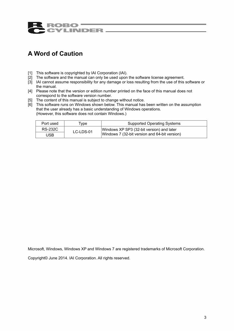
A Word of Caution [1] This software is copyrighted by IAI Corporation (IAI). [2] The software and the manual can only be used upon the software license agreement. [3] IAI cannot assume responsibility for any damage or loss resulting from the use of this software or
the manual. [4] Please note that the version or edition number printed on the face of this manual does not
correspond to the software version number. [5] The content of this manual is subject to change without notice. [6] This software runs on Windows shown below. This manual has been written on the assumption
that the user already has a basic understanding of Windows operations. (However, this software does not contain Windows.)
Port used Type Supported Operating Systems RS-232C
USB LC-LDS-01 Windows XP SP3 (32-bit version) and later
Windows 7 (32-bit version and 64-bit version)
Microsoft, Windows, Windows XP and Windows 7 are registered trademarks of Microsoft Corporation. Copyright© June 2014. IAI Corporation. All rights reserved.

4
Safety Guide “Safety Guide” has been written to use the machine safely and so prevent personal injury or property damage beforehand. Make sure to read it 4before the operation of this product.
Safety Precautions for Our Products The common safety precautions for the use of any of our robots in each operation.
No. Operation Description Description
1 Model Selection
● This product has not been planned and designed for the application where high level of safety is required, so the guarantee of the protection of human life is impossible. Accordingly, do not use it in any of the following applications. 1) Medical equipment used to maintain, control or otherwise affect human
life or physical health. 2) Mechanisms and machinery designed for the purpose of moving or
transporting people (For vehicle, railway facility or air navigation facility)
3) Important safety parts of machinery (Safety device, etc.) ● Do not use the product outside the specifications. Failure to do so may
considerably shorten the life of the product. ● Do not use it in any of the following environments.
1) Location where there is any inflammable gas, inflammable object or explosive
2) Place with potential exposure to radiation 3) Location with the ambient temperature or relative humidity exceeding
the specification range 4) Location where radiant heat is added from direct sunlight or other large
heat source 5) Location where condensation occurs due to abrupt temperature
changes 6) Location where there is any corrosive gas (sulfuric acid or hydrochloric
acid) 7) Location exposed to significant amount of dust, salt or iron powder 8) Location subject to direct vibration or impact
● For an actuator used in vertical orientation, select a model which is equipped with a brake. If selecting a model with no brake, the moving part may drop when the power is turned OFF and may cause an accident such as an injury or damage on the work piece.

5
No. Operation Description Description
2 Transportation ● When carrying a heavy object, do the work with two or more persons or utilize equipment such as crane.
● When the work is carried out with 2 or more persons, make it clear who is to be the leader and who to be the follower(s) and communicate well with each other to ensure the safety of the workers.
● When in transportation, consider well about the positions to hold, weight and weight balance and pay special attention to the carried object so it would not get hit or dropped.
● Transport it using an appropriate transportation measure. The actuators available for transportation with a crane have eyebolts attached or there are tapped holes to attach bolts. Follow the instructions in the instruction manual for each model.
● Do not step or sit on the package. ● Do not put any heavy thing that can deform the package, on it. ● When using a crane capable of 1t or more of weight, have an operator
who has qualifications for crane operation and sling work. ● When using a crane or equivalent equipments, make sure not to hang a
load that weighs more than the equipment’s capability limit. ● Use a hook that is suitable for the load. Consider the safety factor of the
hook in such factors as shear strength. ● Do not get on the load that is hung on a crane. ● Do not leave a load hung up with a crane. ● Do not stand under the load that is hung up with a crane.
3 Storage and Preservation
● The storage and preservation environment conforms to the installation environment. However, especially give consideration to the prevention of condensation.
● Store the products with a consideration not to fall them over or drop due to an act of God such as earthquake.
4 Installation and Start
(1) Installation of Robot Main Body and Controller, etc. ● Make sure to securely hold and fix the product (including the work part). A
fall, drop or abnormal motion of the product may cause a damage or injury. Also, be equipped for a fall-over or drop due to an act of God such as earthquake.
● Do not get on or put anything on the product. Failure to do so may cause an accidental fall, injury or damage to the product due to a drop of anything, malfunction of the product, performance degradation, or shortening of its life.
● When using the product in any of the places specified below, provide a sufficient shield. 1) Location where electric noise is generated 2) Location where high electrical or magnetic field is present 3) Location with the mains or power lines passing nearby 4) Location where the product may come in contact with water, oil or
chemical droplets

6
No. Operation Description Description
(2) Cable Wiring ● Use our company’s genuine cables for connecting between the actuator
and controller, and for the teaching tool. ● Do not scratch on the cable. Do not bend it forcibly. Do not pull it. Do not
coil it around. Do not insert it. Do not put any heavy thing on it. Failure to do so may cause a fire, electric shock or malfunction due to leakage or continuity error.
● Perform the wiring for the product, after turning OFF the power to the unit, so that there is no wiring error.
● When the direct current power (+24V) is connected, take the great care of the directions of positive and negative poles. If the connection direction is not correct, it might cause a fire, product breakdown or malfunction.
● Connect the cable connector securely so that there is no disconnection or looseness. Failure to do so may cause a fire, electric shock or malfunction of the product.
● Never cut and/or reconnect the cables supplied with the product for the purpose of extending or shortening the cable length. Failure to do so may cause the product to malfunction or cause fire.
4 Installation and Start
(3) Grounding ● The grounding operation should be performed to prevent an electric
shock or electrostatic charge, enhance the noise-resistance ability and control the unnecessary electromagnetic radiation.
● For the ground terminal on the AC power cable of the controller and the grounding plate in the control panel, make sure to use a twisted pair cable with wire thickness 0.5mm2 (AWG20 or equivalent) or more for grounding work. For security grounding, it is necessary to select an appropriate wire thickness suitable for the load. Perform wiring that satisfies the specifications (electrical equipment technical standards).
● Perform Class D Grounding (former Class 3 Grounding with ground resistance 100Ω or below).

7
No. Operation Description Description
4 Installation and Start
(4) Safety Measures ● When the work is carried out with 2 or more persons, make it clear who is
to be the leader and who to be the follower(s) and communicate well with each other to ensure the safety of the workers.
● When the product is under operation or in the ready mode, take the safety measures (such as the installation of safety and protection fence) so that nobody can enter the area within the robot’s movable range. When the robot under operation is touched, it may result in death or serious injury.
● Make sure to install the emergency stop circuit so that the unit can be stopped immediately in an emergency during the unit operation.
● Take the safety measure not to start up the unit only with the power turning ON. Failure to do so may start up the machine suddenly and cause an injury or damage to the product.
● Take the safety measure not to start up the machine only with the emergency stop cancellation or recovery after the power failure. Failure to do so may result in an electric shock or injury due to unexpected power input.
● When the installation or adjustment operation is to be performed, give clear warnings such as “Under Operation; Do not turn ON the power!” etc. Sudden power input may cause an electric shock or injury.
● Take the measure so that the work part is not dropped in power failure or emergency stop.
● Wear protection gloves, goggle or safety shoes, as necessary, to secure safety.
● Do not insert a finger or object in the openings in the product. Failure to do so may cause an injury, electric shock, damage to the product or fire.
● When releasing the brake on a vertically oriented actuator, exercise precaution not to pinch your hand or damage the work parts with the actuator dropped by gravity.
5 Teaching ● When the work is carried out with 2 or more persons, make it clear who is to be the leader and who to be the follower(s) and communicate well with each other to ensure the safety of the workers.
● Perform the teaching operation from outside the safety protection fence, if possible. In the case that the operation is to be performed unavoidably inside the safety protection fence, prepare the “Stipulations for the Operation” and make sure that all the workers acknowledge and understand them well.
● When the operation is to be performed inside the safety protection fence, the worker should have an emergency stop switch at hand with him so that the unit can be stopped any time in an emergency.
● When the operation is to be performed inside the safety protection fence, in addition to the workers, arrange a watchman so that the machine can be stopped any time in an emergency. Also, keep watch on the operation so that any third person can not operate the switches carelessly.
● Place a sign “Under Operation” at the position easy to see. ● When releasing the brake on a vertically oriented actuator, exercise
precaution not to pinch your hand or damage the work parts with the actuator dropped by gravity.
* Safety protection Fence : In the case that there is no safety protection fence, the movable range should be indicated.

8
No. Operation Description Description
6 Trial Operation ● When the work is carried out with 2 or more persons, make it clear who is to be the leader and who to be the follower(s) and communicate well with each other to ensure the safety of the workers.
● After the teaching or programming operation, perform the check operation one step by one step and then shift to the automatic operation.
● When the check operation is to be performed inside the safety protection fence, perform the check operation using the previously specified work procedure like the teaching operation.
● Make sure to perform the programmed operation check at the safety speed. Failure to do so may result in an accident due to unexpected motion caused by a program error, etc.
● Do not touch the terminal block or any of the various setting switches in the power ON mode. Failure to do so may result in an electric shock or malfunction.
7 Automatic Operation
● Check before starting the automatic operation or rebooting after operation stop that there is nobody in the safety protection fence.
● Before starting automatic operation, make sure that all peripheral equipment is in an automatic-operation-ready state and there is no alarm indication.
● Make sure to operate automatic operation start from outside of the safety protection fence.
● In the case that there is any abnormal heating, smoke, offensive smell, or abnormal noise in the product, immediately stop the machine and turn OFF the power switch. Failure to do so may result in a fire or damage to the product.
● When a power failure occurs, turn OFF the power switch. Failure to do so may cause an injury or damage to the product, due to a sudden motion of the product in the recovery operation from the power failure.

9
No. Operation Description Description
8 Maintenance and Inspection
● When the work is carried out with 2 or more persons, make it clear who is to be the leader and who to be the follower(s) and communicate well with each other to ensure the safety of the workers.
● Perform the work out of the safety protection fence, if possible. In the case that the operation is to be performed unavoidably inside the safety protection fence, prepare the “Stipulations for the Operation” and make sure that all the workers acknowledge and understand them well.
● When the work is to be performed inside the safety protection fence, basically turn OFF the power switch.
● When the operation is to be performed inside the safety protection fence, the worker should have an emergency stop switch at hand with him so that the unit can be stopped any time in an emergency.
● When the operation is to be performed inside the safety protection fence, in addition to the workers, arrange a watchman so that the machine can be stopped any time in an emergency. Also, keep watch on the operation so that any third person can not operate the switches carelessly.
● Place a sign “Under Operation” at the position easy to see. ● For the grease for the guide or ball screw, use appropriate grease
according to the instruction manual for each model. ● Do not perform the dielectric strength test. Failure to do so may result in
damage to the product. ● When releasing the brake on a vertically oriented actuator, exercise
precaution not to pinch your hand or damage the work parts with the actuator dropped by gravity.
● The slider or rod may get misaligned OFF the stop position if the servo is turned OFF. Be careful not to get injured or damaged due to an unnecessary operation.
● Pay attention not to lose the cover or untightened screws, and make sure to put the product back to the original condition after maintenance and inspection works. Use in incomplete condition may cause damage to the product or an injury.
* Safety protection Fence: In the case that there is no safety protection fence, the movable range should be indicated.
9 Modification and Dismantle
● Do not modify, disassemble, assemble or use of maintenance parts not specified based at your own discretion.
10 Disposal ● When the product becomes no longer usable or necessary, dispose of it properly as an industrial waste.
● When removing the actuator for disposal, pay attention to drop of components when detaching screws.
● Do not put the product in a fire when disposing of it. The product may burst or generate toxic gases.
11 Other ● Do not come close to the product or the harnesses if you are a person who requires a support of medical devices such as a pacemaker. Doing so may affect the performance of your medical device.
● See Overseas Specifications Compliance Manual to check whether complies if necessary.
● For the handling of actuators and controllers, follow the dedicated instruction manual of each unit to ensure the safety.

10
Alert Indication The safety precautions are divided into “Danger”, “Warning”, “Caution” and “Notice” according to the warning level, as follows, and described in the instruction manual for each model.
Level Degree of Danger and Damage Symbol
Danger This indicates an imminently hazardous situation which, if the product is not handled correctly, will result in death or serious injury.
Danger
Warning This indicates a potentially hazardous situation which, if the product is not handled correctly, could result in death or serious injury.
Warning
Caution This indicates a potentially hazardous situation which, if the product is not handled correctly, may result in minor injury or property damage.
Caution
Notice This indicates lower possibility for the injury, but should be kept to use this product properly.
Notice
1. Please Read Before U
se
11
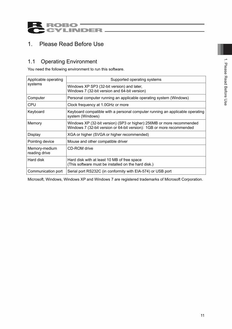
1. Please Read Before Use 1.1 Operating Environment You need the following environment to run this software.
Supported operating systems Applicable operating systems Windows XP SP3 (32-bit version) and later,
Windows 7 (32-bit version and 64-bit version)
Computer Personal computer running an applicable operating system (Windows)
CPU Clock frequency at 1.0GHz or more
Keyboard Keyboard compatible with a personal computer running an applicable operating system (Windows)
Memory Windows XP (32-bit version) (SP3 or higher): 256MB or more recommended Windows 7 (32-bit version or 64-bit version): 1GB or more recommended
Display XGA or higher (SVGA or higher recommended)
Pointing device Mouse and other compatible driver
Memory-medium reading drive
CD-ROM drive
Hard disk Hard disk with at least 10 MB of free space (This software must be installed on the hard disk.)
Communication port Serial port RS232C (in conformity with EIA-574) or USB port
Microsoft, Windows, Windows XP and Windows 7 are registered trademarks of Microsoft Corporation.
1. P
leas
e R
ead
Befo
re U
se
12
1.2 How to Install This software is run from the hard disk. Follow the steps below to install this software.
1) Boot up the Windows. 2) Execute [Setup.exe] in the installed program to start the setup program.
For Windows 7, a confirmation dialog for the user account control appears. Click on [Yes] button.
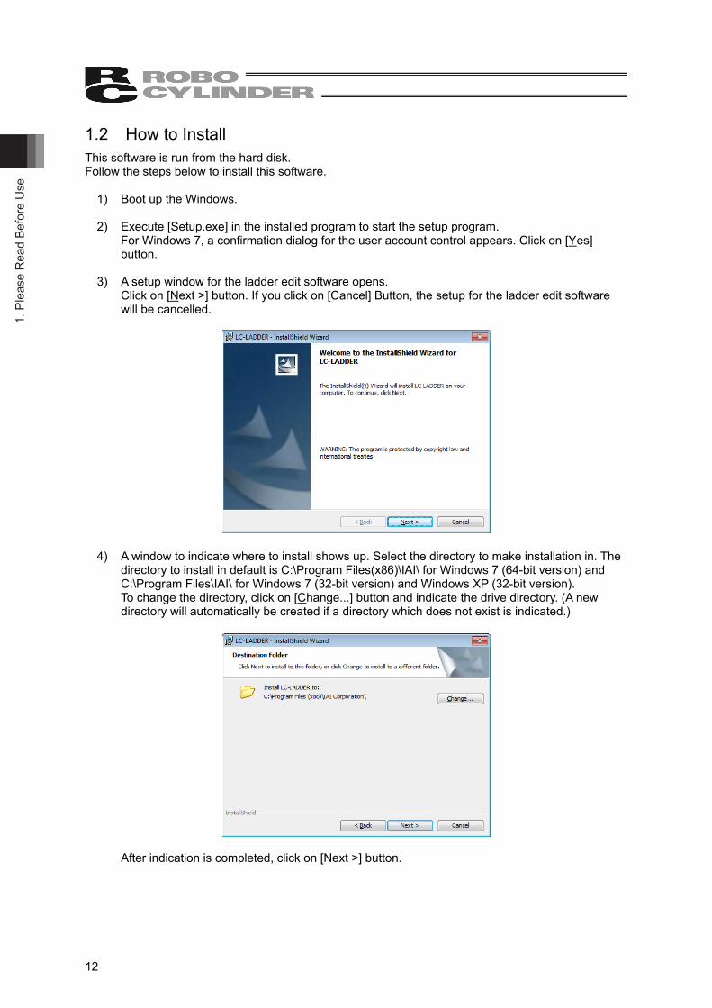
3) A setup window for the ladder edit software opens.
Click on [Next >] button. If you click on [Cancel] Button, the setup for the ladder edit software will be cancelled.
4) A window to indicate where to install shows up. Select the directory to make installation in. The directory to install in default is C:\Program Files(x86)\IAI\ for Windows 7 (64-bit version) and C:\Program Files\IAI\ for Windows 7 (32-bit version) and Windows XP (32-bit version). To change the directory, click on [Change...] button and indicate the drive directory. (A new directory will automatically be created if a directory which does not exist is indicated.)
After indication is completed, click on [Next >] button.
1. Please Read Before U
se
13
(Note) Once installation is conducted, “LC” folder is created in the indicated install folder, and in “LC” folder, there will be “LC-LADDER” and “INTACORE” folders created. e.g. If the directory to install is in default;
For Windows 7 (64-bit version) C:\Program Files (×86)\IAI\LC\LC-LADDER: Execution modules of the ladder edit
software are stored C:\Program Files (×86)\IAI\LC\INTACORE: Files used in the test run are stored
For Windows 7 (32-bit version) and Windows XP (32-bit version) C:\Program Files\IAI\LC\LC-LADDER C:\Program Files\IAI\LC\INTACORE
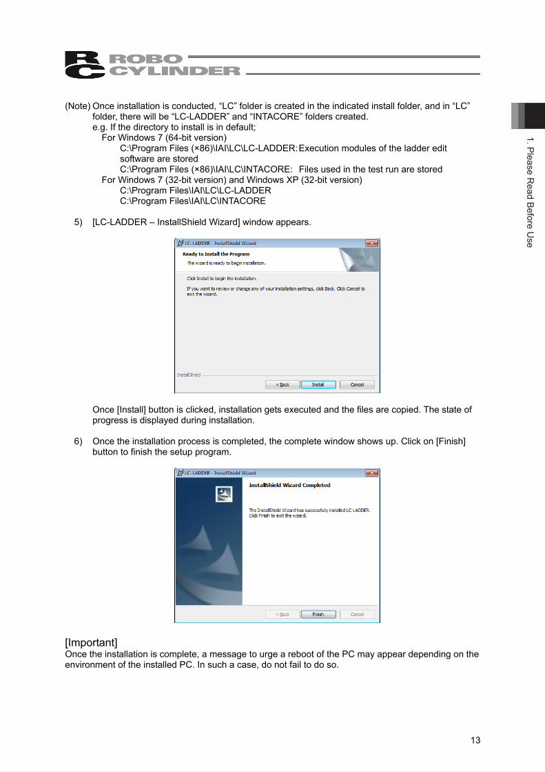
5) [LC-LADDER – InstallShield Wizard] window appears.
Once [Install] button is clicked, installation gets executed and the files are copied. The state of
progress is displayed during installation. 6) Once the installation process is completed, the complete window shows up. Click on [Finish]
button to finish the setup program.
[Important] Once the installation is complete, a message to urge a reboot of the PC may appear depending on the environment of the installed PC. In such a case, do not fail to do so.
1. P
leas
e R
ead
Befo
re U
se
14
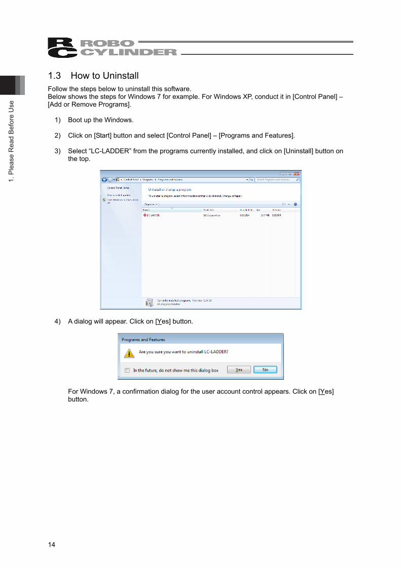
1.3 How to Uninstall Follow the steps below to uninstall this software. Below shows the steps for Windows 7 for example. For Windows XP, conduct it in [Control Panel] – [Add or Remove Programs].
1) Boot up the Windows. 2) Click on [Start] button and select [Control Panel] – [Programs and Features]. 3) Select “LC-LADDER” from the programs currently installed, and click on [Uninstall] button on
the top.
4) A dialog will appear. Click on [Yes] button.
For Windows 7, a confirmation dialog for the user account control appears. Click on [Yes]
button.

1. Please Read Before U
se
15
1.4 How to Reinstall Follow the steps below to uninstall this software. Below shows the steps for Windows 7 for example.
1) Remove the ladder edit software by following “1.3 How to Uninstall”. After removing, open
[Programs and Features] and confirm that the ladder edit software is not in the list. 2) Install the ladder edit software by following “1.2 How to Install”. 3) If a message telling you that the file is already installed is shown during the installation process,
cancel the installation process, remove the ladder edit software again by following “1.3 How to Uninstall”, and then conduct the installation process again.
2. S
tartu
p an
d Sh
utdo
wn
16
2. Startup and Shutdown 2.1 Startup and Shutdown of Ladder Edit Software 2.1.1 Startup
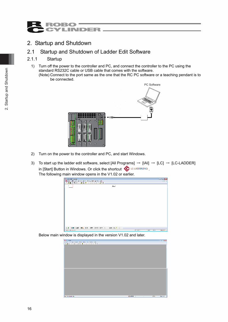
1) Turn off the power to the controller and PC, and connect the controller to the PC using the standard RS232C cable or USB cable that comes with the software. (Note) Connect to the port same as the one that the RC PC software or a teaching pendant is to
be connected. PC Software
2) Turn on the power to the controller and PC, and start Windows. 3) To start up the ladder edit software, select [All Programs] → [IAI] → [LC] → [LC-LADDER]
in [Start] Button in Windows. Or click the shortcut . The following main window opens in the V1.02 or earlier.
Below main window is displayed in the version V1.02 and later.
2. Startup and Shutdown
17
2.1.2 Shutdown The ladder edit software can be finished by either of the following processes:
• Select [Exit] in [Project] menu. • Click on button on the top right of the main window. • Double-clicik the icon on the top left of the main window. • Click the icon on the top left of the main window, select [Close] in the appeared control menu box. • Hold down [Alt] key and press [F4] key.
(Note) A confirmation message is shown when finishing if the data of an open project is not saved. 2.2 Start and Finish of Simulation (Test Run) By writing the ladder program in the test run program to operate on the PC, the ladder program can be simulated (test run) without the actual controller. [Refer to 9. Simulation (Test Run)] 2.2.1 Start
1) Select [Test] in [Tool] menu in the ladder edit software. (Note) When writing in a program in the test run, select [Program Writing] in [Online] in the
ladder edit software. 2.2.2 Finish The test run finishes automatically when the ladder edit software is finished.
3.Pr
ojec
t Man
agem
ent
18
3. Project Management 3.1 Creating New Project Start up the ladder edit software, and a new project Ladder1 opens in Version V1.01 or earlier. New project Ladder1 not opens in Version V1.02 or later. If two or more ladder programs are required to be created in the same time, follow the steps below to add a new project.
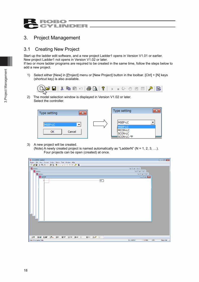
1) Select either [New] in [Project] menu or [New Project] button in the toolbar. [Ctrl] + [N] keys (shortcut key) is also available.
2) The model selection window is displayed in Version V1.02 or later.
Select the controller.
3) A new project will be created. (Note) A newly created project is named automatically as “LadderN” (N = 1, 2, 3, …).
Four projects can be open (created) at once.
3. Project Managem
ent
19
3.2 Overwriting Project to Save Follow the steps below to overwrite a project. The created ladder program can be saved. Note that [Save Project As] dialog will show up for a new project that has never been saved. Save the project by following the steps stated in “3.3 Save Project As”.
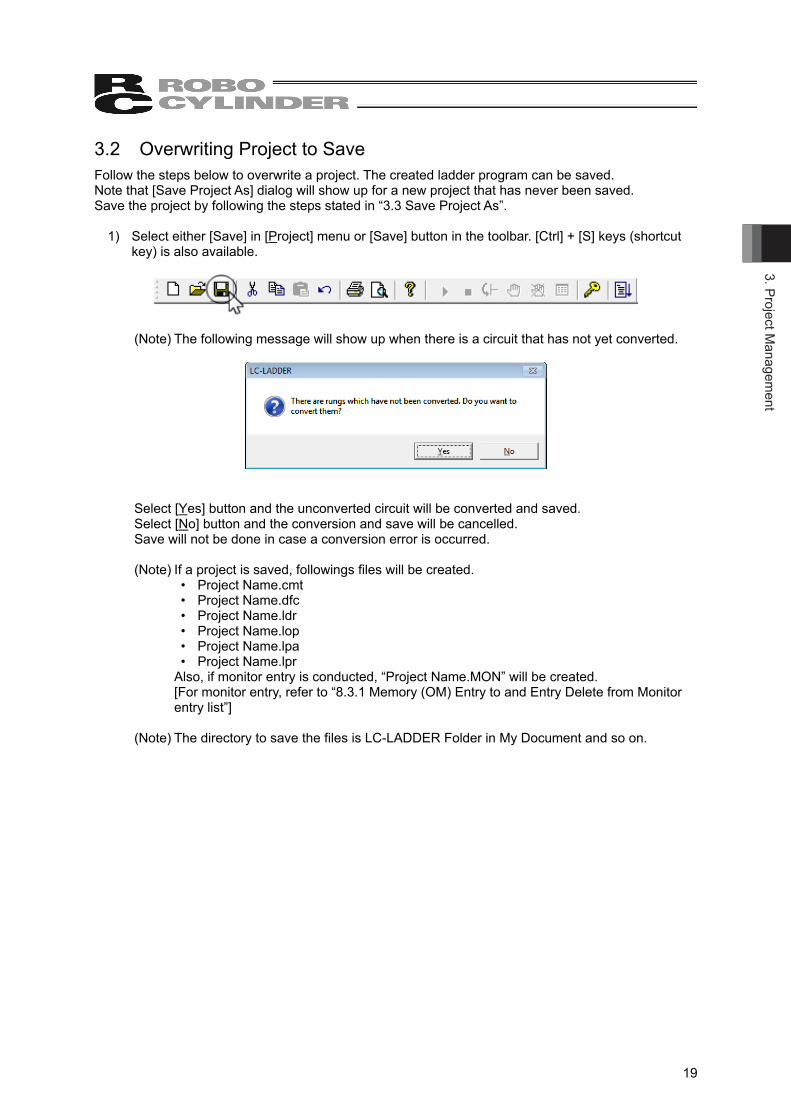
1) Select either [Save] in [Project] menu or [Save] button in the toolbar. [Ctrl] + [S] keys (shortcut key) is also available.
(Note) The following message will show up when there is a circuit that has not yet converted.
Select [Yes] button and the unconverted circuit will be converted and saved. Select [No] button and the conversion and save will be cancelled. Save will not be done in case a conversion error is occurred. (Note) If a project is saved, followings files will be created.
• Project Name.cmt • Project Name.dfc • Project Name.ldr • Project Name.lop • Project Name.lpa • Project Name.lpr
Also, if monitor entry is conducted, “Project Name.MON” will be created. [For monitor entry, refer to “8.3.1 Memory (OM) Entry to and Entry Delete from Monitor entry list”]
(Note) The directory to save the files is LC-LADDER Folder in My Document and so on.
3.Pr
ojec
t Man
agem
ent
20
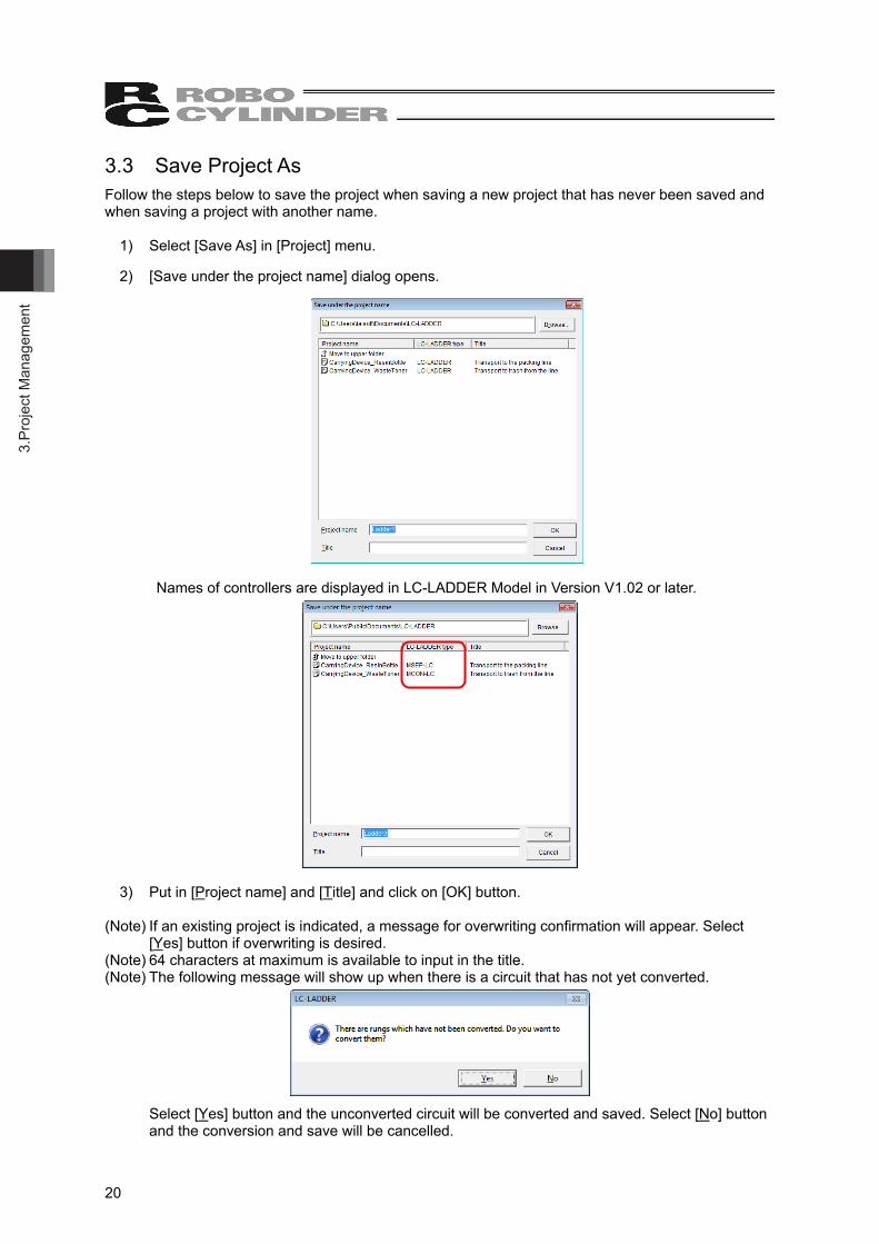
3.3 Save Project As Follow the steps below to save the project when saving a new project that has never been saved and when saving a project with another name.
1) Select [Save As] in [Project] menu. 2) [Save under the project name] dialog opens.
Names of controllers are displayed in LC-LADDER Model in Version V1.02 or later.
3) Put in [Project name] and [Title] and click on [OK] button. (Note) If an existing project is indicated, a message for overwriting confirmation will appear. Select
[Yes] button if overwriting is desired. (Note) 64 characters at maximum is available to input in the title. (Note) The following message will show up when there is a circuit that has not yet converted.
Select [Yes] button and the unconverted circuit will be converted and saved. Select [No] button
and the conversion and save will be cancelled.
3. Project Managem
ent
21
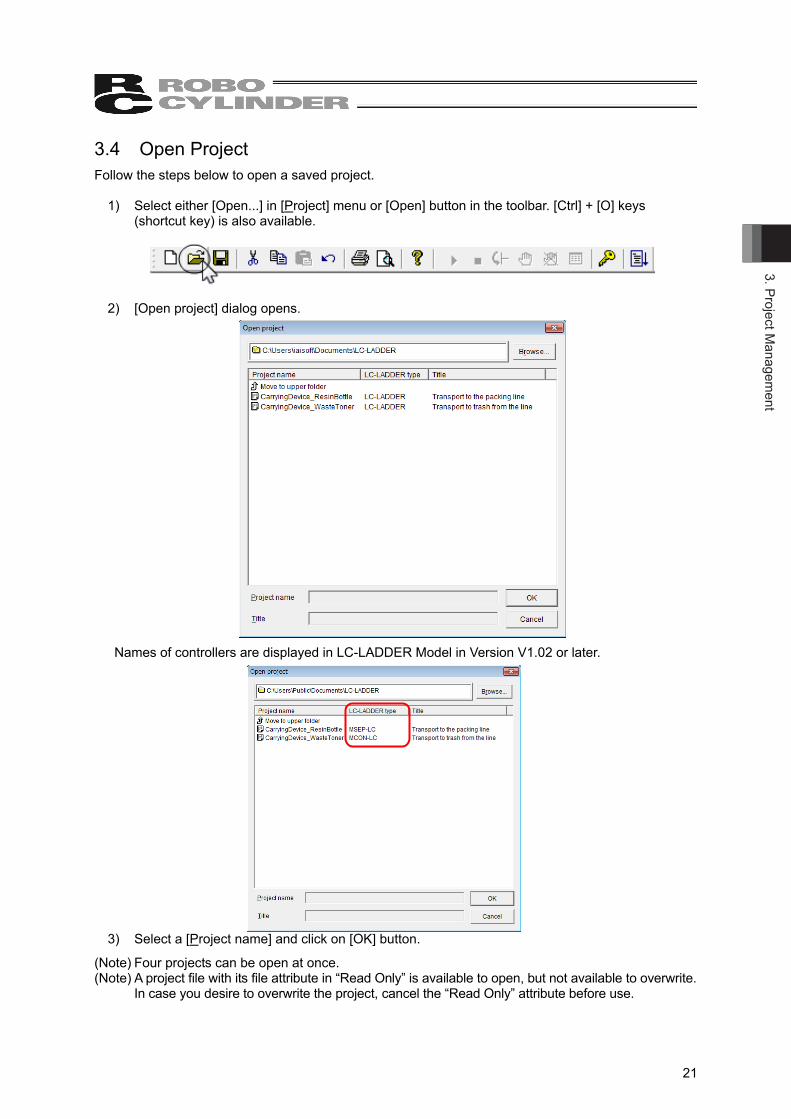
3.4 Open Project Follow the steps below to open a saved project.
1) Select either [Open...] in [Project] menu or [Open] button in the toolbar. [Ctrl] + [O] keys (shortcut key) is also available.
2) [Open project] dialog opens.
Names of controllers are displayed in LC-LADDER Model in Version V1.02 or later.
3) Select a [Project name] and click on [OK] button.
(Note) Four projects can be open at once. (Note) A project file with its file attribute in “Read Only” is available to open, but not available to overwrite.
In case you desire to overwrite the project, cancel the “Read Only” attribute before use.
3.Pr
ojec
t Man
agem
ent
22
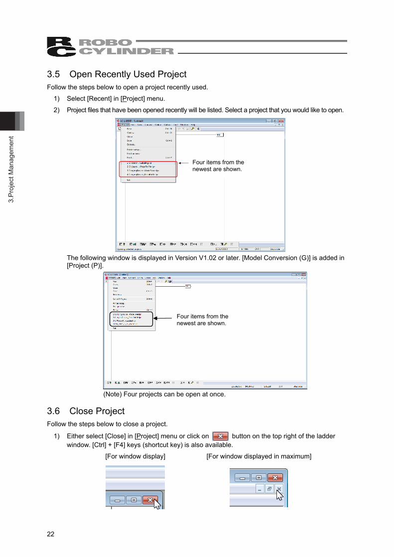
3.5 Open Recently Used Project Follow the steps below to open a project recently used.
1) Select [Recent] in [Project] menu.
2) Project files that have been opened recently will be listed. Select a project that you would like to open.
Four items from the latest are shown.
The following window is displayed in Version V1.02 or later. [Model Conversion (G)] is added in [Project (P)].
(Note) Four projects can be open at once.
3.6 Close Project Follow the steps below to close a project.
1) Either select [Close] in [Project] menu or click on button on the top right of the ladder window. [Ctrl] + [F4] keys (shortcut key) is also available.
[For window display] [For window displayed in maximum]
Four items from the newest are shown.
Four items from the newest are shown.
4. Creating Ladder Program
23
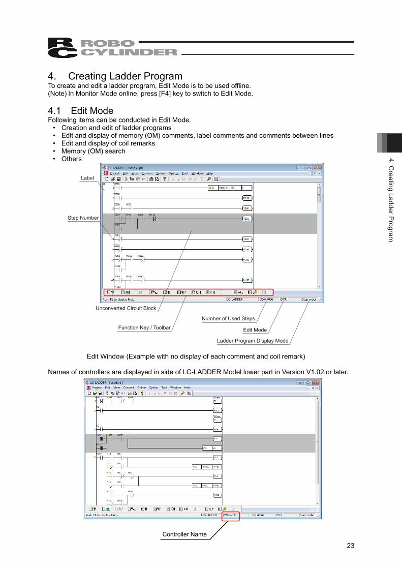
4. Creating Ladder Program To create and edit a ladder program, Edit Mode is to be used offline. (Note) In Monitor Mode online, press [F4] key to switch to Edit Mode. 4.1 Edit Mode Following items can be conducted in Edit Mode.
• Creation and edit of ladder programs • Edit and display of memory (OM) comments, label comments and comments between lines • Edit and display of coil remarks • Memory (OM) search • Others
Label
Step Number
Unconverted Circuit Block
Function Key / Toolbar
Number of Used Steps
Edit Mode
Ladder Program Display Mode
Edit Window (Example with no display of each comment and coil remark)
Names of controllers are displayed in side of LC-LADDER Model lower part in Version V1.02 or later.
Controller Name

4. C
reat
ing
Ladd
er P
rogr
am
24
There are Overwrite Mode and Insert Mode in Edit Mode. It is displayed in Overwrite Mode when the ladder edit software is activating. Also, there is an edit lock function to prohibit editing. <Overwrite Mode> Press [Insert] key in Insert Mode and it switches to Overwrite Mode. Overwrite
Mode is a mode that a command or ladder program is overwritten at the cursor position in an operation such as input of a ladder program command or pasting of a ladder program.
<Insert Mode> Press [Insert] key in Overwrite Mode and it switches to Insert Mode. Insert Mode is a mode that a command or ladder program is inserted at the cursor position in an operation such as input of a ladder program command or pasting of a ladder program.
<Edit Lock> There is a function called “Edit Lock” which prohibits edit of program to prevent any unexpected overwriting of a ladder program in Edit Mode. While in edit lock, not only change in ladder program, but edit of each comment such as memory (OM) comment and coil remark are also prohibited. [Refer to 4.6.11 Edit Lock]
4. Creating Ladder Program
25
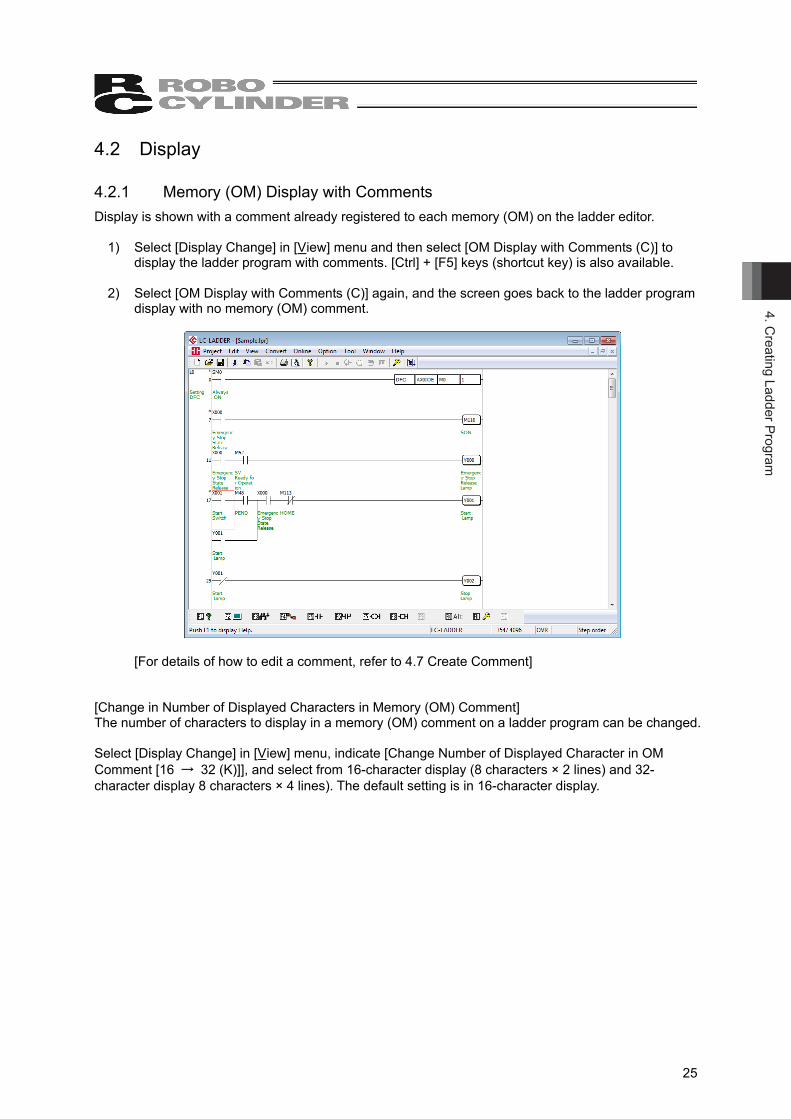
4.2 Display 4.2.1 Memory (OM) Display with Comments Display is shown with a comment already registered to each memory (OM) on the ladder editor.
1) Select [Display Change] in [View] menu and then select [OM Display with Comments (C)] to display the ladder program with comments. [Ctrl] + [F5] keys (shortcut key) is also available.
2) Select [OM Display with Comments (C)] again, and the screen goes back to the ladder program
display with no memory (OM) comment.
[For details of how to edit a comment, refer to 4.7 Create Comment] [Change in Number of Displayed Characters in Memory (OM) Comment] The number of characters to display in a memory (OM) comment on a ladder program can be changed. Select [Display Change] in [View] menu, indicate [Change Number of Displayed Character in OM Comment [16 → 32 (K)]], and select from 16-character display (8 characters × 2 lines) and 32-character display 8 characters × 4 lines). The default setting is in 16-character display.
4. C
reat
ing
Ladd
er P
rogr
am
26
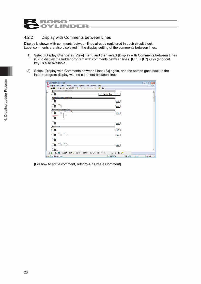
4.2.2 Display with Comments between Lines Display is shown with comments between lines already registered in each circuit block. Label comments are also displayed in the display setting of the comments between lines.
1) Select [Display Change] in [View] menu and then select [Display with Comments between Lines (S)] to display the ladder program with comments between lines. [Ctrl] + [F7] keys (shortcut key) is also available.
2) Select [Display with Comments between Lines (S)] again, and the screen goes back to the
ladder program display with no comment between lines.
[For how to edit a comment, refer to 4.7 Create Comment]
4. Creating Ladder Program
27
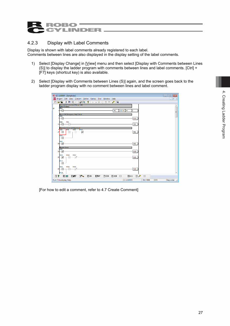
4.2.3 Display with Label Comments Display is shown with label comments already registered to each label. Comments between lines are also displayed in the display setting of the label comments.
1) Select [Display Change] in [View] menu and then select [Display with Comments between Lines (S)] to display the ladder program with comments between lines and label comments. [Ctrl] + [F7] keys (shortcut key) is also available.
2) Select [Display with Comments between Lines (S)] again, and the screen goes back to the
ladder program display with no comment between lines and label comment.
[For how to edit a comment, refer to 4.7 Create Comment]
4. C
reat
ing
Ladd
er P
rogr
am
28
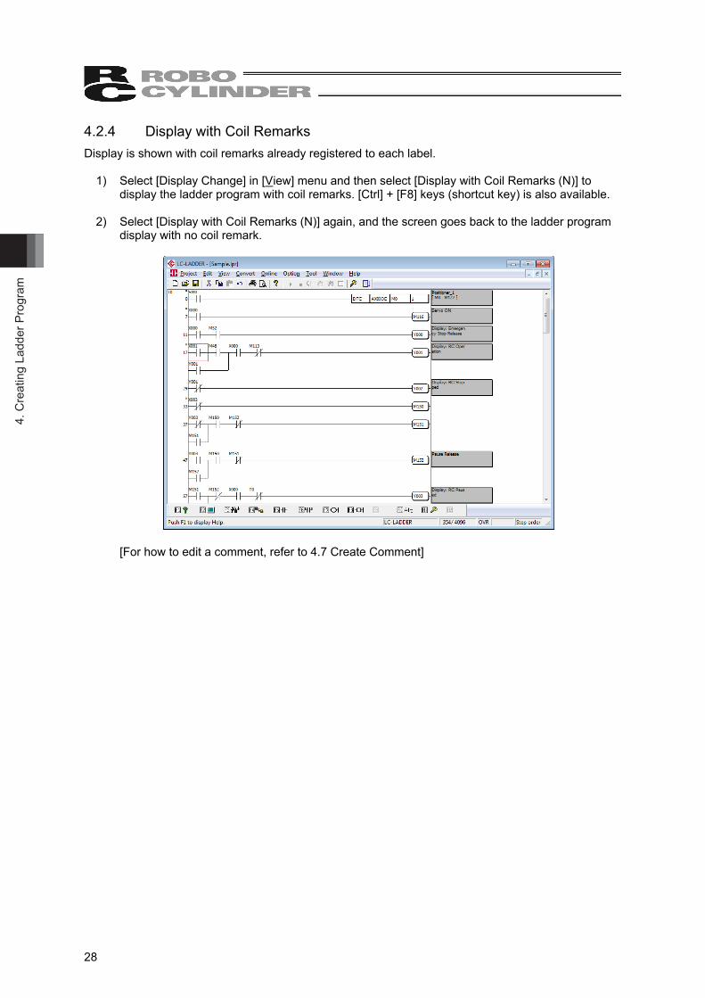
4.2.4 Display with Coil Remarks Display is shown with coil remarks already registered to each label.
1) Select [Display Change] in [View] menu and then select [Display with Coil Remarks (N)] to
display the ladder program with coil remarks. [Ctrl] + [F8] keys (shortcut key) is also available. 2) Select [Display with Coil Remarks (N)] again, and the screen goes back to the ladder program
display with no coil remark.
[For how to edit a comment, refer to 4.7 Create Comment]
4. Creating Ladder Program
29
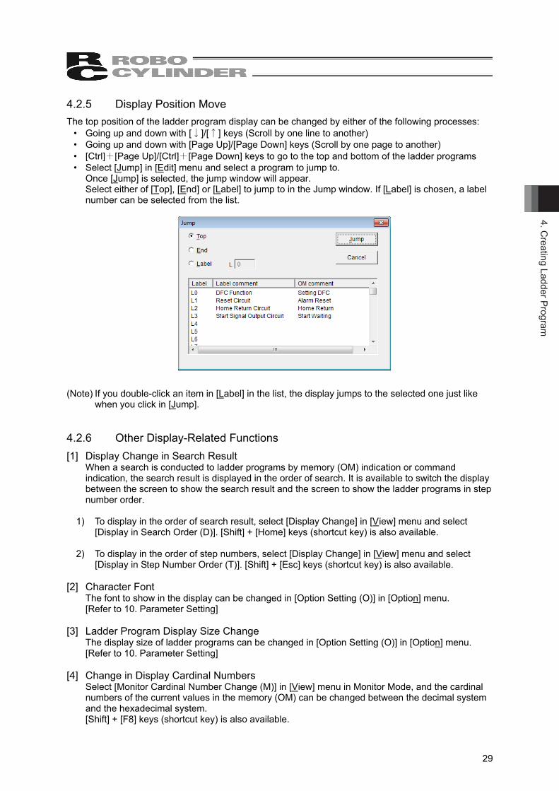
4.2.5 Display Position Move The top position of the ladder program display can be changed by either of the following processes:
• Going up and down with [↓]/[↑] keys (Scroll by one line to another) • Going up and down with [Page Up]/[Page Down] keys (Scroll by one page to another) • [Ctrl]+[Page Up]/[Ctrl]+[Page Down] keys to go to the top and bottom of the ladder programs • Select [Jump] in [Edit] menu and select a program to jump to.
Once [Jump] is selected, the jump window will appear. Select either of [Top], [End] or [Label] to jump to in the Jump window. If [Label] is chosen, a label number can be selected from the list.
(Note) If you double-click an item in [Label] in the list, the display jumps to the selected one just like when you click in [Jump].
4.2.6 Other Display-Related Functions [1] Display Change in Search Result
When a search is conducted to ladder programs by memory (OM) indication or command indication, the search result is displayed in the order of search. It is available to switch the display between the screen to show the search result and the screen to show the ladder programs in step number order.
1) To display in the order of search result, select [Display Change] in [View] menu and select
[Display in Search Order (D)]. [Shift] + [Home] keys (shortcut key) is also available. 2) To display in the order of step numbers, select [Display Change] in [View] menu and select
[Display in Step Number Order (T)]. [Shift] + [Esc] keys (shortcut key) is also available.
[2] Character Font The font to show in the display can be changed in [Option Setting (O)] in [Option] menu. [Refer to 10. Parameter Setting]
[3] Ladder Program Display Size Change The display size of ladder programs can be changed in [Option Setting (O)] in [Option] menu. [Refer to 10. Parameter Setting]
[4] Change in Display Cardinal Numbers Select [Monitor Cardinal Number Change (M)] in [View] menu in Monitor Mode, and the cardinal numbers of the current values in the memory (OM) can be changed between the decimal system and the hexadecimal system. [Shift] + [F8] keys (shortcut key) is also available.
4. C
reat
ing
Ladd
er P
rogr
am
30
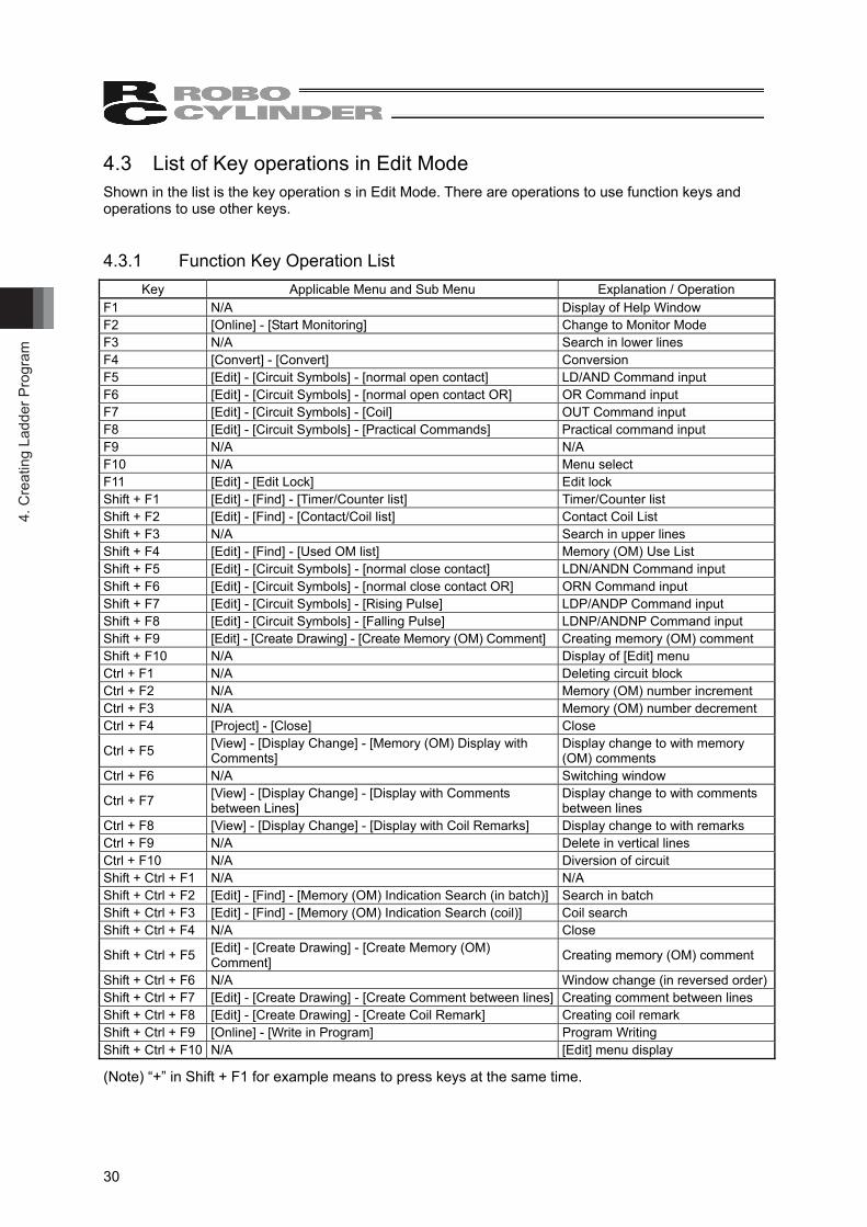
4.3 List of Key operations in Edit Mode Shown in the list is the key operation s in Edit Mode. There are operations to use function keys and operations to use other keys. 4.3.1 Function Key Operation List
Key Applicable Menu and Sub Menu Explanation / Operation F1 N/A Display of Help Window F2 [Online] - [Start Monitoring] Change to Monitor Mode F3 N/A Search in lower lines F4 [Convert] - [Convert] Conversion F5 [Edit] - [Circuit Symbols] - [normal open contact] LD/AND Command input F6 [Edit] - [Circuit Symbols] - [normal open contact OR] OR Command input F7 [Edit] - [Circuit Symbols] - [Coil] OUT Command input F8 [Edit] - [Circuit Symbols] - [Practical Commands] Practical command input F9 N/A N/A F10 N/A Menu select F11 [Edit] - [Edit Lock] Edit lock Shift + F1 [Edit] - [Find] - [Timer/Counter list] Timer/Counter list Shift + F2 [Edit] - [Find] - [Contact/Coil list] Contact Coil List Shift + F3 N/A Search in upper lines Shift + F4 [Edit] - [Find] - [Used OM list] Memory (OM) Use List Shift + F5 [Edit] - [Circuit Symbols] - [normal close contact] LDN/ANDN Command input Shift + F6 [Edit] - [Circuit Symbols] - [normal close contact OR] ORN Command input Shift + F7 [Edit] - [Circuit Symbols] - [Rising Pulse] LDP/ANDP Command input Shift + F8 [Edit] - [Circuit Symbols] - [Falling Pulse] LDNP/ANDNP Command input Shift + F9 [Edit] - [Create Drawing] - [Create Memory (OM) Comment] Creating memory (OM) comment Shift + F10 N/A Display of [Edit] menu Ctrl + F1 N/A Deleting circuit block Ctrl + F2 N/A Memory (OM) number increment Ctrl + F3 N/A Memory (OM) number decrement Ctrl + F4 [Project] - [Close] Close
Ctrl + F5 [View] - [Display Change] - [Memory (OM) Display with Comments]
Display change to with memory (OM) comments
Ctrl + F6 N/A Switching window
Ctrl + F7 [View] - [Display Change] - [Display with Comments between Lines]
Display change to with comments between lines
Ctrl + F8 [View] - [Display Change] - [Display with Coil Remarks] Display change to with remarks Ctrl + F9 N/A Delete in vertical lines Ctrl + F10 N/A Diversion of circuit Shift + Ctrl + F1 N/A N/A Shift + Ctrl + F2 [Edit] - [Find] - [Memory (OM) Indication Search (in batch)] Search in batch Shift + Ctrl + F3 [Edit] - [Find] - [Memory (OM) Indication Search (coil)] Coil search Shift + Ctrl + F4 N/A Close
Shift + Ctrl + F5 [Edit] - [Create Drawing] - [Create Memory (OM) Comment] Creating memory (OM) comment
Shift + Ctrl + F6 N/A Window change (in reversed order)Shift + Ctrl + F7 [Edit] - [Create Drawing] - [Create Comment between lines] Creating comment between lines Shift + Ctrl + F8 [Edit] - [Create Drawing] - [Create Coil Remark] Creating coil remark Shift + Ctrl + F9 [Online] - [Write in Program] Program Writing Shift + Ctrl + F10 N/A [Edit] menu display
(Note) “+” in Shift + F1 for example means to press keys at the same time.
4. Creating Ladder Program
31
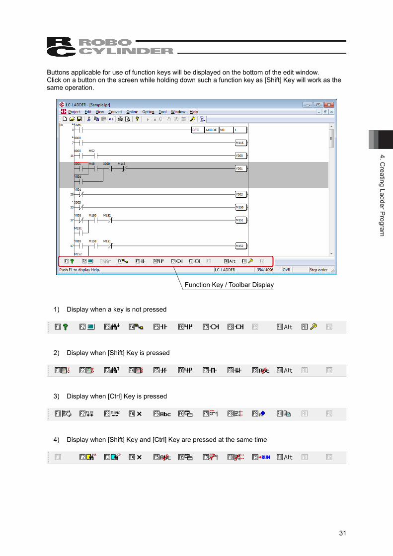
Buttons applicable for use of function keys will be displayed on the bottom of the edit window. Click on a button on the screen while holding down such a function key as [Shift] Key will work as the same operation.
1) Display when a key is not pressed
2) Display when [Shift] Key is pressed
3) Display when [Ctrl] Key is pressed
4) Display when [Shift] Key and [Ctrl] Key are pressed at the same time
Function Key / Toolbar Display
4. C
reat
ing
Ladd
er P
rogr
am
32
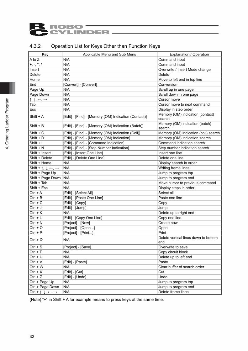
4.3.2 Operation List for Keys Other than Function Keys Key Applicable Menu and Sub Menu Explanation / Operation
A to Z N/A Command input +, -, *, / N/A Command input Insert N/A Overwrite / Insert Mode change Delete N/A Delete Home N/A Move to left end in top line End [Convert] - [Convert] Conversion Page Up N/A Scroll up in one page Page Down N/A Scroll down in one page ↑, ↓, ←, → N/A Cursor move Tab N/A Cursor move to next command Esc N/A Display in step order
Shift + A [Edit] - [Find] - [Memory (OM) Indication (Contact)] Memory (OM) indication (contact) search
Shift + B [Edit] - [Find] - [Memory (OM) Indication (Batch)] Memory (OM) indication (batch) search
Shift + C [Edit] - [Find] - [Memory (OM) Indication (Coil)] Memory (OM) indication (coil) searchShift + D [Edit] - [Find] - [Memory (OM) Indication] Memory (OM) indication search Shift + I [Edit] - [Find] - [Command Indication] Command indication search Shift + N [Edit] - [Find] - [Step Number Indication] Step number indication search Shift + Insert [Edit] - [Insert One Line] Insert one line Shift + Delete [Edit] - [Delete One Line] Delete one line Shift + Home N/A Display search in order Shift + ↑, ↓, ←, → N/A Writing frame lines Shift + Page Up N/A Jump to program top Shift + Page Down N/A Jump to program end Shift + Tab N/A Move cursor to previous command Shift + Esc N/A Display steps in order Ctrl + A [Edit] - [Select All] Select all Ctrl + B [Edit] - [Paste One Line] Paste one line Ctrl + C [Edit] - [Copy] Copy Ctrl + J [Edit] - [Jump] Jump Ctrl + K N/A Delete up to right end Ctrl + L [Edit] - [Copy One Line] Copy one line Ctrl + N [Project] - [New] Create new Ctrl + O [Project] - [Open...] Open Ctrl + P [Project] - [Print...] Print
Ctrl + Q N/A Delete vertical lines down to bottom end
Ctrl + S [Project] - [Save] Overwrite to save Ctrl + T N/A Copy circuit block Ctrl + U N/A Delete up to left end Ctrl + V [Edit] - [Paste] Paste Ctrl + W N/A Clear buffer of search order Ctrl + X [Edit] - [Cut] Cut Ctrl + Z [Edit] - [Undo] Undo Ctrl + Page Up N/A Jump to program top Ctrl + Page Down N/A Jump to program end Ctrl + ↑, ↓, ←, → N/A Delete frame lines
(Note) “+” in Shift + A for example means to press keys at the same time.
4. Creating Ladder Program
33
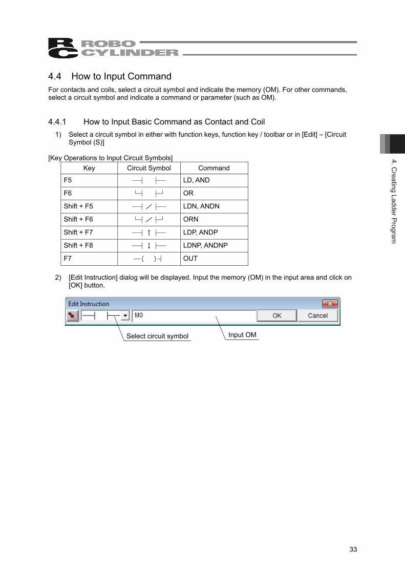
4.4 How to Input Command For contacts and coils, select a circuit symbol and indicate the memory (OM). For other commands, select a circuit symbol and indicate a command or parameter (such as OM). 4.4.1 How to Input Basic Command as Contact and Coil
1) Select a circuit symbol in either with function keys, function key / toolbar or in [Edit] – [Circuit Symbol (S)]
[Key Operations to Input Circuit Symbols]
Key Circuit Symbol Command
F5 ─┤ ├─ LD, AND
F6 └┤ ├┘ OR
Shift + F5 ─┤/├─ LDN, ANDN
Shift + F6 └┤/├┘ ORN
Shift + F7 ─┤↑├─ LDP, ANDP
Shift + F8 ─┤↓├─ LDNP, ANDNP
F7 ─( )┤ OUT
2) [Edit Instruction] dialog will be displayed. Input the memory (OM) in the input area and click on [OK] button.
Select circuit symbol Input OM
4. C
reat
ing
Ladd
er P
rogr
am
34
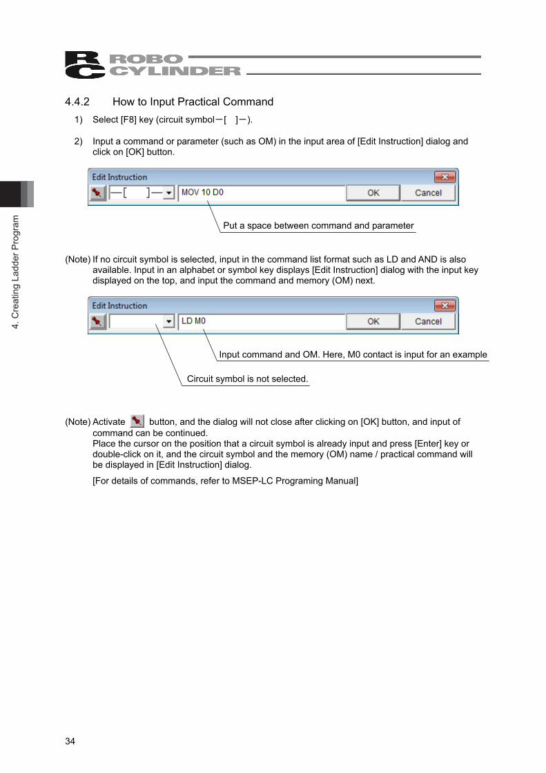
4.4.2 How to Input Practical Command 1) Select [F8] key (circuit symbol-[ ]-). 2) Input a command or parameter (such as OM) in the input area of [Edit Instruction] dialog and
click on [OK] button.
(Note) If no circuit symbol is selected, input in the command list format such as LD and AND is also available. Input in an alphabet or symbol key displays [Edit Instruction] dialog with the input key displayed on the top, and input the command and memory (OM) next.
(Note) Activate button, and the dialog will not close after clicking on [OK] button, and input of command can be continued. Place the cursor on the position that a circuit symbol is already input and press [Enter] key or double-click on it, and the circuit symbol and the memory (OM) name / practical command will be displayed in [Edit Instruction] dialog.
[For details of commands, refer to MSEP-LC Programing Manual]
Put a space between command and parameter
Input command and OM. Here, M0 contact is input for an example
Circuit symbol is not selected.
4. Creating Ladder Program
35
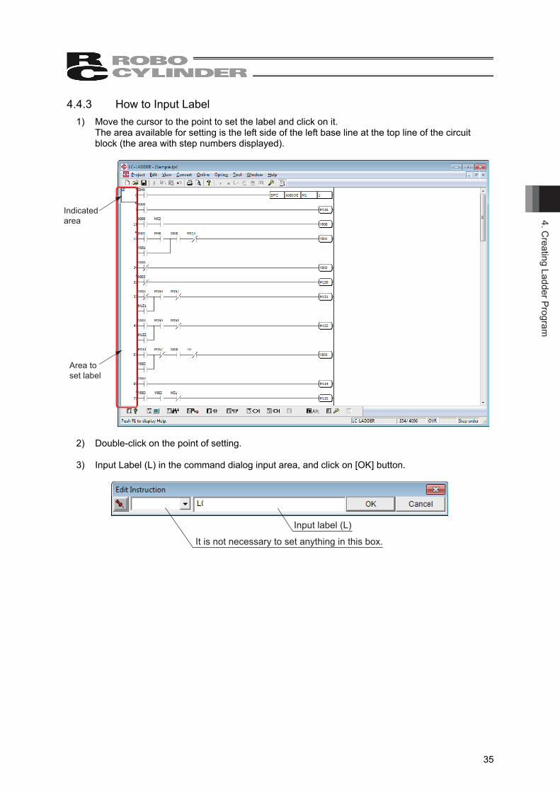
4.4.3 How to Input Label 1) Move the cursor to the point to set the label and click on it.
The area available for setting is the left side of the left base line at the top line of the circuit block (the area with step numbers displayed).
Indicated area
Area to set label
2) Double-click on the point of setting. 3) Input Label (L) in the command dialog input area, and click on [OK] button.
Input label (L)
It is not necessary to set anything in this box.
4. C
reat
ing
Ladd
er P
rogr
am
36
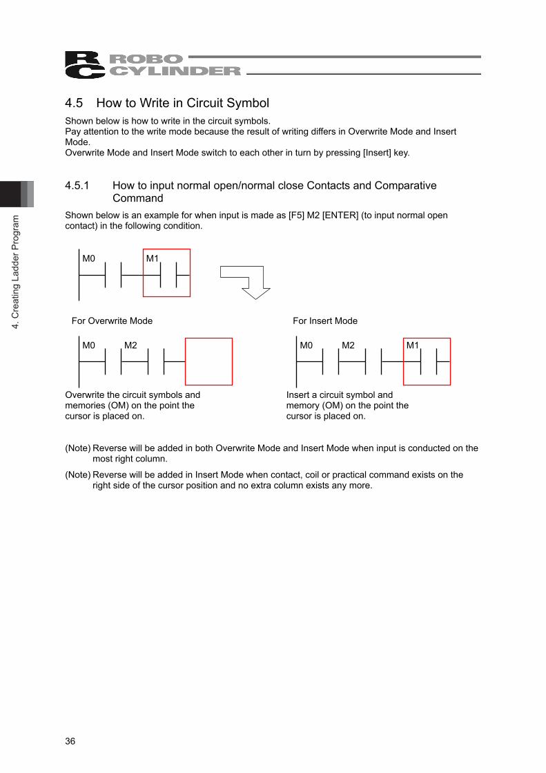
4.5 How to Write in Circuit Symbol Shown below is how to write in the circuit symbols. Pay attention to the write mode because the result of writing differs in Overwrite Mode and Insert Mode. Overwrite Mode and Insert Mode switch to each other in turn by pressing [Insert] key. 4.5.1 How to input normal open/normal close Contacts and Comparative
Command Shown below is an example for when input is made as [F5] M2 [ENTER] (to input normal open contact) in the following condition. For Overwrite Mode For Insert Mode Overwrite the circuit symbols and Insert a circuit symbol and memories (OM) on the point the memory (OM) on the point the cursor is placed on. cursor is placed on.
(Note) Reverse will be added in both Overwrite Mode and Insert Mode when input is conducted on the most right column.
(Note) Reverse will be added in Insert Mode when contact, coil or practical command exists on the right side of the cursor position and no extra column exists any more.
M0 M2 M1 M0 M2
M0 M1
4. Creating Ladder Program
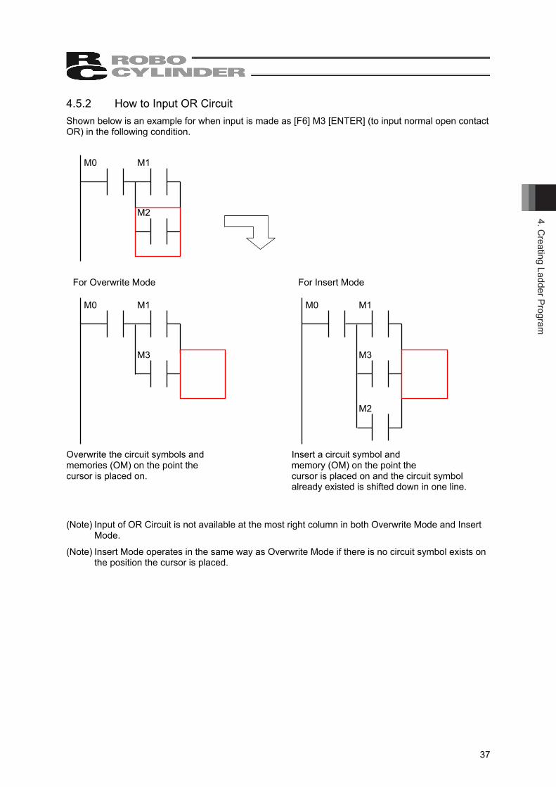
37
4.5.2 How to Input OR Circuit Shown below is an example for when input is made as [F6] M3 [ENTER] (to input normal open contact OR) in the following condition. For Overwrite Mode For Insert Mode Overwrite the circuit symbols and Insert a circuit symbol and memories (OM) on the point the memory (OM) on the point the cursor is placed on. cursor is placed on and the circuit symbol already existed is shifted down in one line.
(Note) Input of OR Circuit is not available at the most right column in both Overwrite Mode and Insert Mode.
(Note) Insert Mode operates in the same way as Overwrite Mode if there is no circuit symbol exists on the position the cursor is placed.
M0 M1
M3
M2
M0 M1
M3
M0 M1
M2
4. C
reat
ing
Ladd
er P
rogr
am
38
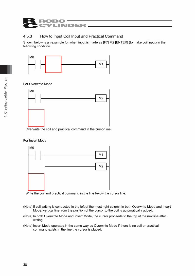
4.5.3 How to Input Coil Input and Practical Command Shown below is an example for when input is made as [F7] M2 [ENTER] (to make coil input) in the following condition. For Overwrite Mode Overwrite the coil and practical command in the cursor line. For Insert Mode Write the coil and practical command in the line below the cursor line.
(Note) If coil writing is conducted in the left of the most right column in both Overwrite Mode and Insert Mode, vertical line from the position of the cursor to the coil is automatically added.
(Note) In both Overwrite Mode and Insert Mode, the cursor proceeds to the top of the nextline after writing.
(Note) Insert Mode operates in the same way as Overwrite Mode if there is no coil or practical command exists in the line the cursor is placed.
M0
M2
M0
M1
M2
M0
M1
4. Creating Ladder Program
39
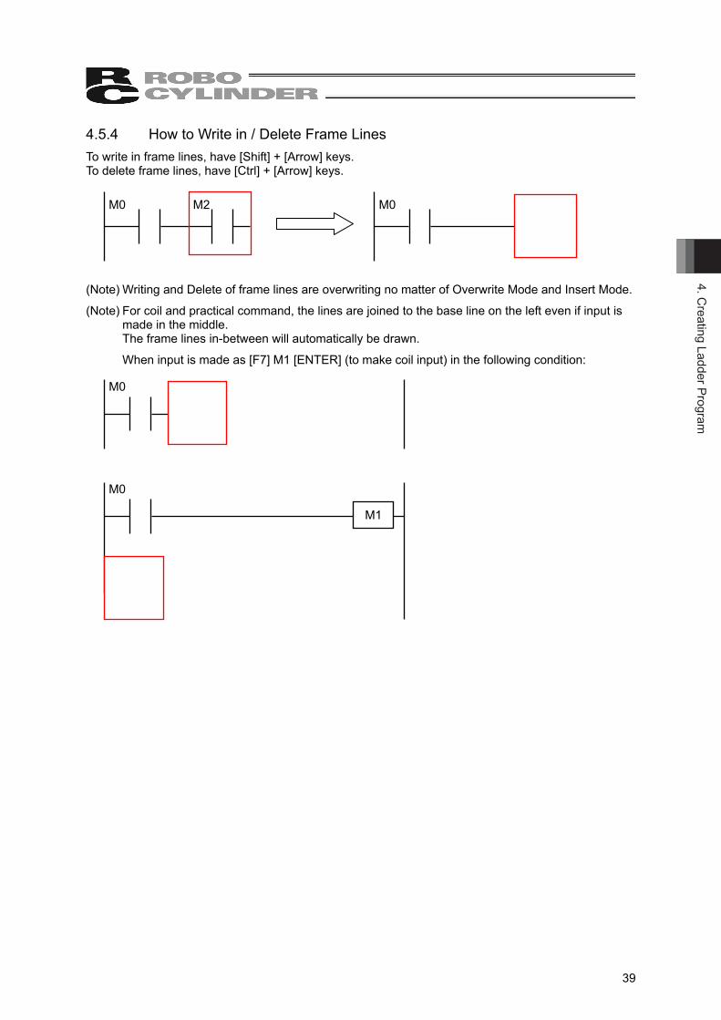
4.5.4 How to Write in / Delete Frame Lines To write in frame lines, have [Shift] + [Arrow] keys. To delete frame lines, have [Ctrl] + [Arrow] keys.
(Note) Writing and Delete of frame lines are overwriting no matter of Overwrite Mode and Insert Mode.
(Note) For coil and practical command, the lines are joined to the base line on the left even if input is made in the middle. The frame lines in-between will automatically be drawn.
When input is made as [F7] M1 [ENTER] (to make coil input) in the following condition:
M0
M1
M0
M0 M2 M0
4. C
reat
ing
Ladd
er P
rogr
am
40
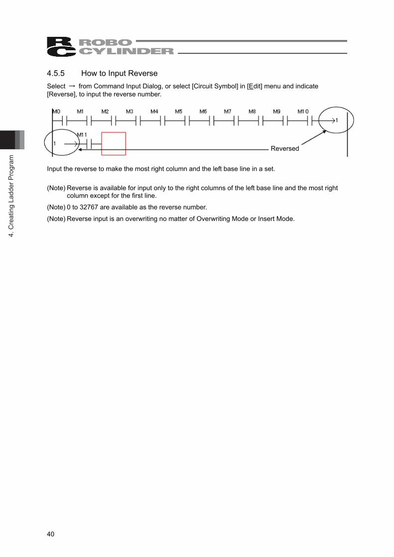
4.5.5 How to Input Reverse Select → from Command Input Dialog, or select [Circuit Symbol] in [Edit] menu and indicate [Reverse], to input the reverse number.
Input the reverse to make the most right column and the left base line in a set.
(Note) Reverse is available for input only to the right columns of the left base line and the most right column except for the first line.
(Note) 0 to 32767 are available as the reverse number.
(Note) Reverse input is an overwriting no matter of Overwriting Mode or Insert Mode.
Reversed
4. Creating Ladder Program
41
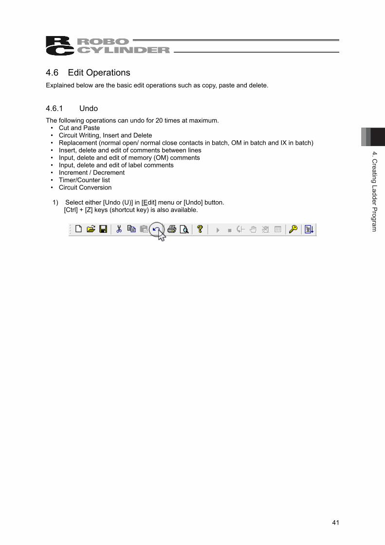
4.6 Edit Operations Explained below are the basic edit operations such as copy, paste and delete. 4.6.1 Undo The following operations can undo for 20 times at maximum.
• Cut and Paste • Circuit Writing, Insert and Delete • Replacement (normal open/ normal close contacts in batch, OM in batch and IX in batch) • Insert, delete and edit of comments between lines • Input, delete and edit of memory (OM) comments • Input, delete and edit of label comments • Increment / Decrement • Timer/Counter list • Circuit Conversion
1) Select either [Undo (U)] in [Edit] menu or [Undo] button.
[Ctrl] + [Z] keys (shortcut key) is also available.
4. C
reat
ing
Ladd
er P
rogr
am
42
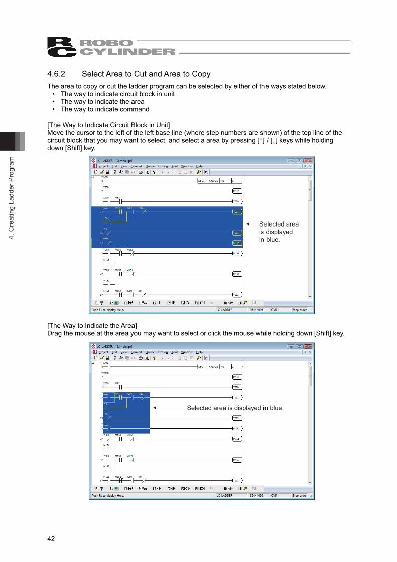
4.6.2 Select Area to Cut and Area to Copy The area to copy or cut the ladder program can be selected by either of the ways stated below.
• The way to indicate circuit block in unit • The way to indicate the area • The way to indicate command
[The Way to Indicate Circuit Block in Unit] Move the cursor to the left of the left base line (where step numbers are shown) of the top line of the circuit block that you may want to select, and select a area by pressing [↑] / [↓] keys while holding down [Shift] key.
Selected area is displayed in blue.
[The Way to Indicate the Area] Drag the mouse at the area you may want to select or click the mouse while holding down [Shift] key.
Selected area is displayed in blue.
4. Creating Ladder Program
43
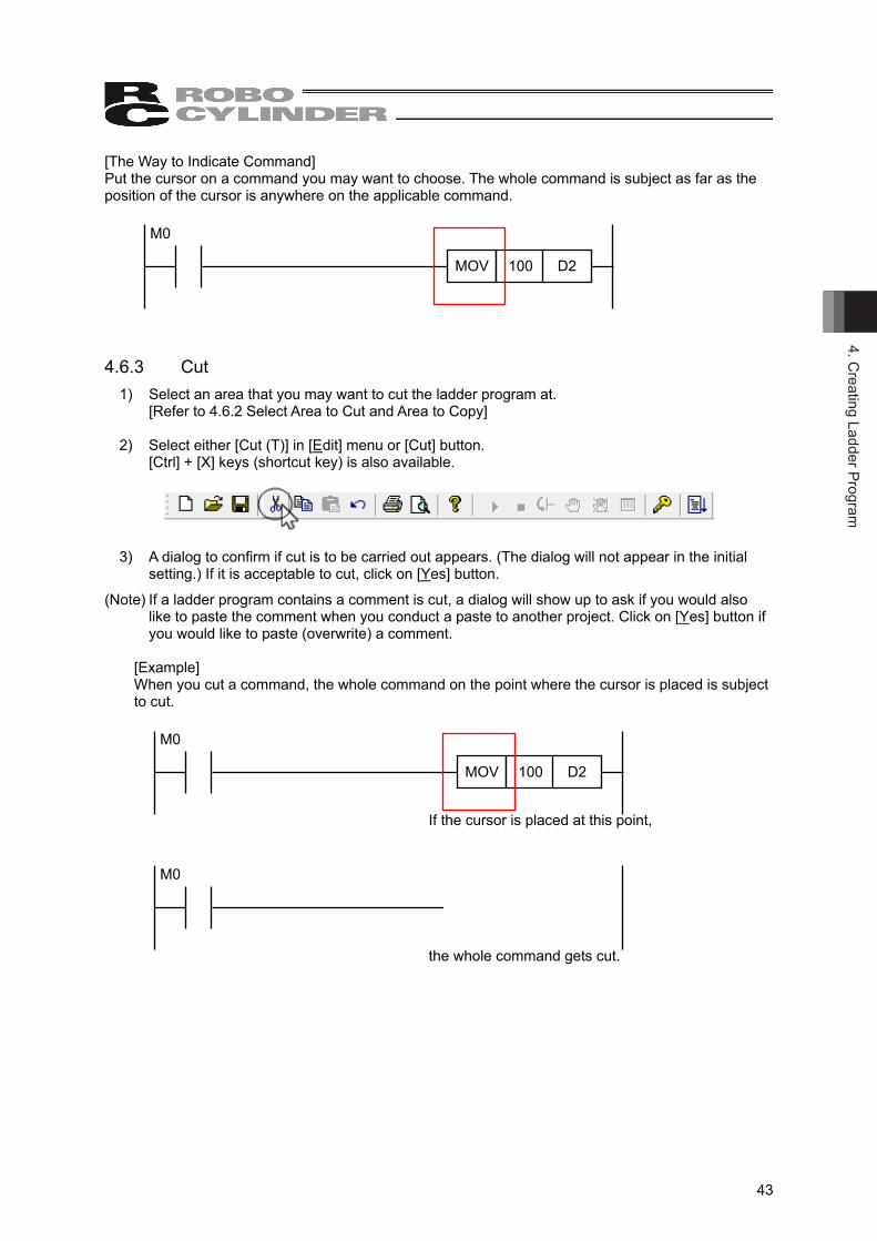
[The Way to Indicate Command] Put the cursor on a command you may want to choose. The whole command is subject as far as the position of the cursor is anywhere on the applicable command. 4.6.3 Cut
1) Select an area that you may want to cut the ladder program at. [Refer to 4.6.2 Select Area to Cut and Area to Copy]
2) Select either [Cut (T)] in [Edit] menu or [Cut] button.
[Ctrl] + [X] keys (shortcut key) is also available.
3) A dialog to confirm if cut is to be carried out appears. (The dialog will not appear in the initial setting.) If it is acceptable to cut, click on [Yes] button.
(Note) If a ladder program contains a comment is cut, a dialog will show up to ask if you would also like to paste the comment when you conduct a paste to another project. Click on [Yes] button if you would like to paste (overwrite) a comment.
[Example] When you cut a command, the whole command on the point where the cursor is placed is subject to cut.
If the cursor is placed at this point, the whole command gets cut.
M0
MOV 100 D2
M0
MOV 100 D2
M0
4. C
reat
ing
Ladd
er P
rogr
am
44
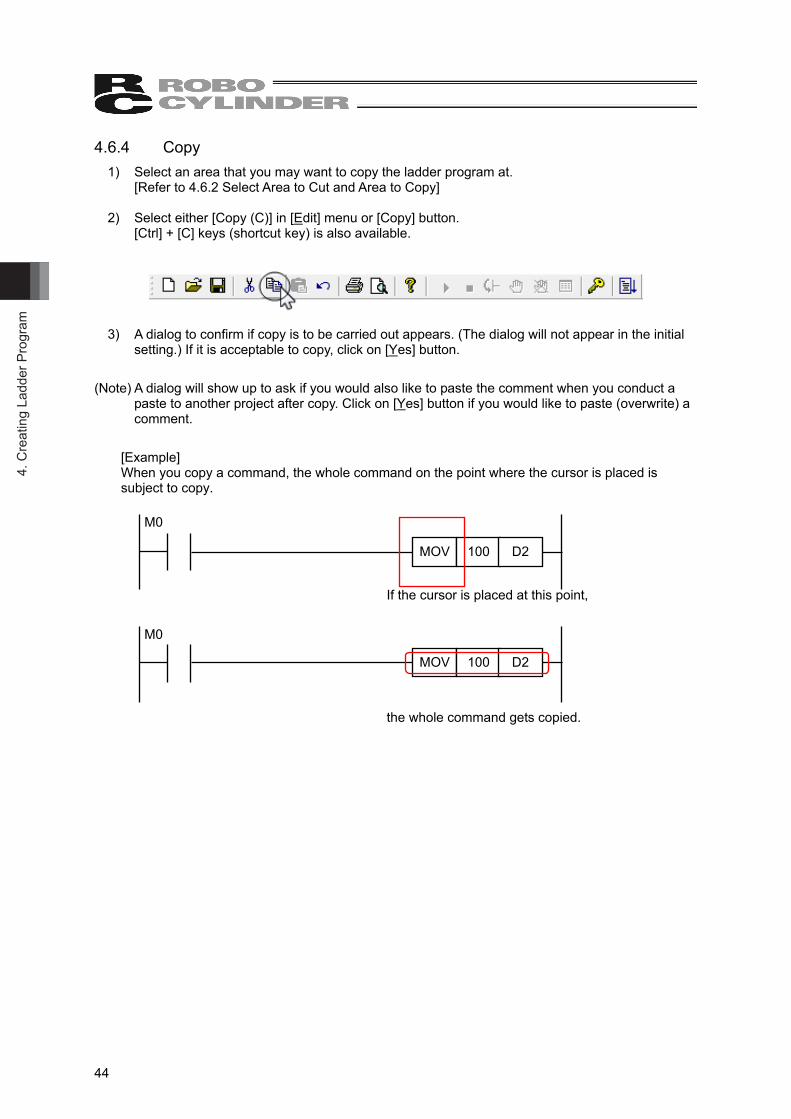
4.6.4 Copy 1) Select an area that you may want to copy the ladder program at.
[Refer to 4.6.2 Select Area to Cut and Area to Copy] 2) Select either [Copy (C)] in [Edit] menu or [Copy] button.
[Ctrl] + [C] keys (shortcut key) is also available.
3) A dialog to confirm if copy is to be carried out appears. (The dialog will not appear in the initial setting.) If it is acceptable to copy, click on [Yes] button.
(Note) A dialog will show up to ask if you would also like to paste the comment when you conduct a paste to another project after copy. Click on [Yes] button if you would like to paste (overwrite) a comment.
[Example] When you copy a command, the whole command on the point where the cursor is placed is subject to copy.
If the cursor is placed at this point, the whole command gets copied.
M0
MOV 100 D2
M0
MOV 100 D2
4. Creating Ladder Program
45
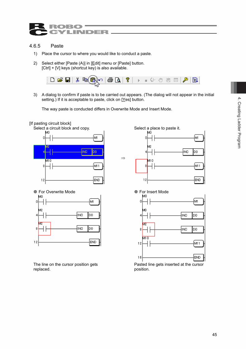
4.6.5 Paste 1) Place the cursor to where you would like to conduct a paste.
2) Select either [Paste (A)] in [Edit] menu or [Paste] button.
[Ctrl] + [V] keys (shortcut key) is also available.
3) A dialog to confirm if paste is to be carried out appears. (The dialog will not appear in the initial setting.) If it is acceptable to paste, click on [Yes] button.
The way paste is conducted differs in Overwrite Mode and Insert Mode.
[If pasting circuit block]
Select a circuit block and copy. Select a place to paste it.
⇒
For Overwrite Mode
For Insert Mode
The line on the cursor position gets replaced. Pasted line gets inserted at the cursor
position.
4. C
reat
ing
Ladd
er P
rogr
am
46
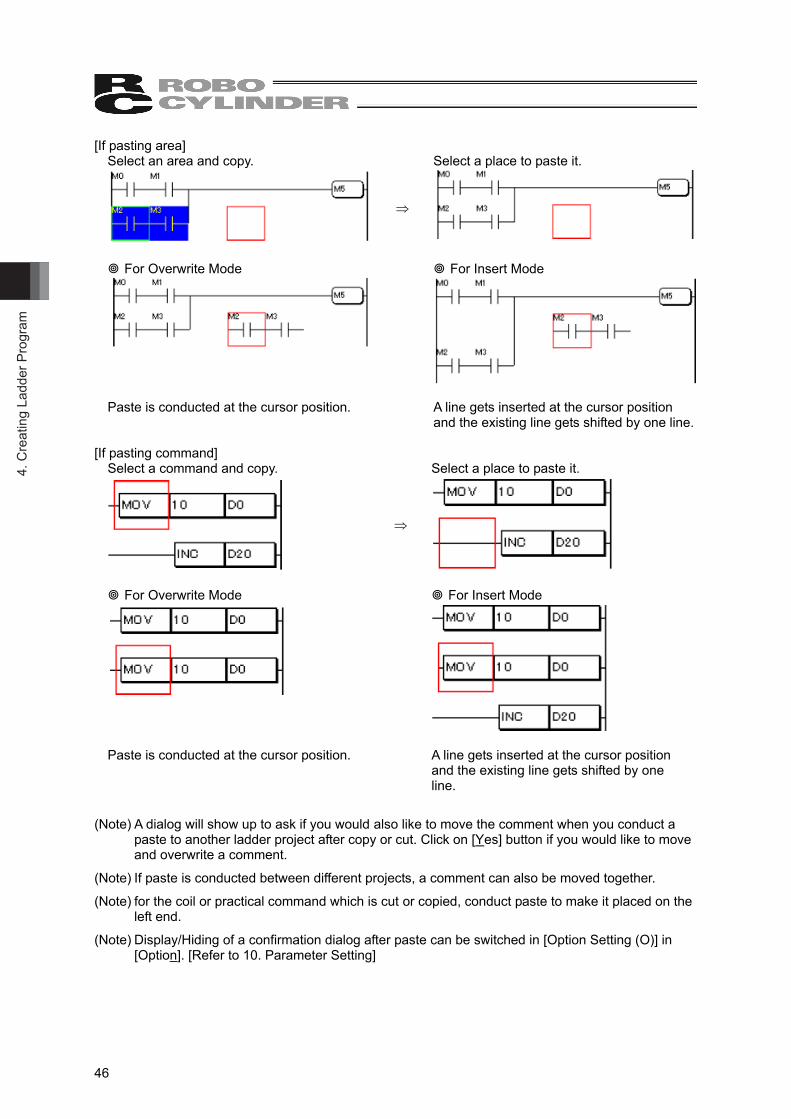
[If pasting area] Select an area and copy. Select a place to paste it.
⇒
For Overwrite Mode
For Insert Mode
Paste is conducted at the cursor position.
A line gets inserted at the cursor position and the existing line gets shifted by one line.
[If pasting command]
Select a command and copy. Select a place to paste it.
⇒
For Overwrite Mode For Insert Mode
Paste is conducted at the cursor position.
A line gets inserted at the cursor position and the existing line gets shifted by one line.
(Note) A dialog will show up to ask if you would also like to move the comment when you conduct a paste to another ladder project after copy or cut. Click on [Yes] button if you would like to move and overwrite a comment.
(Note) If paste is conducted between different projects, a comment can also be moved together.
(Note) for the coil or practical command which is cut or copied, conduct paste to make it placed on the left end.
(Note) Display/Hiding of a confirmation dialog after paste can be switched in [Option Setting (O)] in [Option]. [Refer to 10. Parameter Setting]

4. Creating Ladder Program
47
4.6.6 Insert One Line 1) Place the cursor to the ladder program where you would like to insert one line. 2) Select [Insert One Line (N)] in [Edit] menu and a blank line can be inserted.
[Shift] + [Insert] keys (shortcut key) is also available.
4.6.7 Cut One Line
1) Place the cursor to the ladder program where you would like to cut one line. 2) Select [Cut One Line (E)] in [Edit] menu and a line can be cut.
[Shift] + [Delete] keys (shortcut key) is also available.
(Note) A line cut by Cut One Line can be pasted by operation of [Paste One Line (B)] in [Edit] menu. [Refer to 4.6.9 Paste One Line]
4.6.8 Copy One Line
1) Place the cursor to the ladder program where you would like to copy one line. 2) Select [Copy One Line (L)] in [Edit] menu and a line can be copied.
[Ctrl] + [L] keys (shortcut key) is also available.
(Note) A line copied by Copy One Line can be pasted by operation of [Paste One Line (B)] in [Edit] menu. [Refer to 4.6.9 Paste One Line]
4. C
reat
ing
Ladd
er P
rogr
am
48
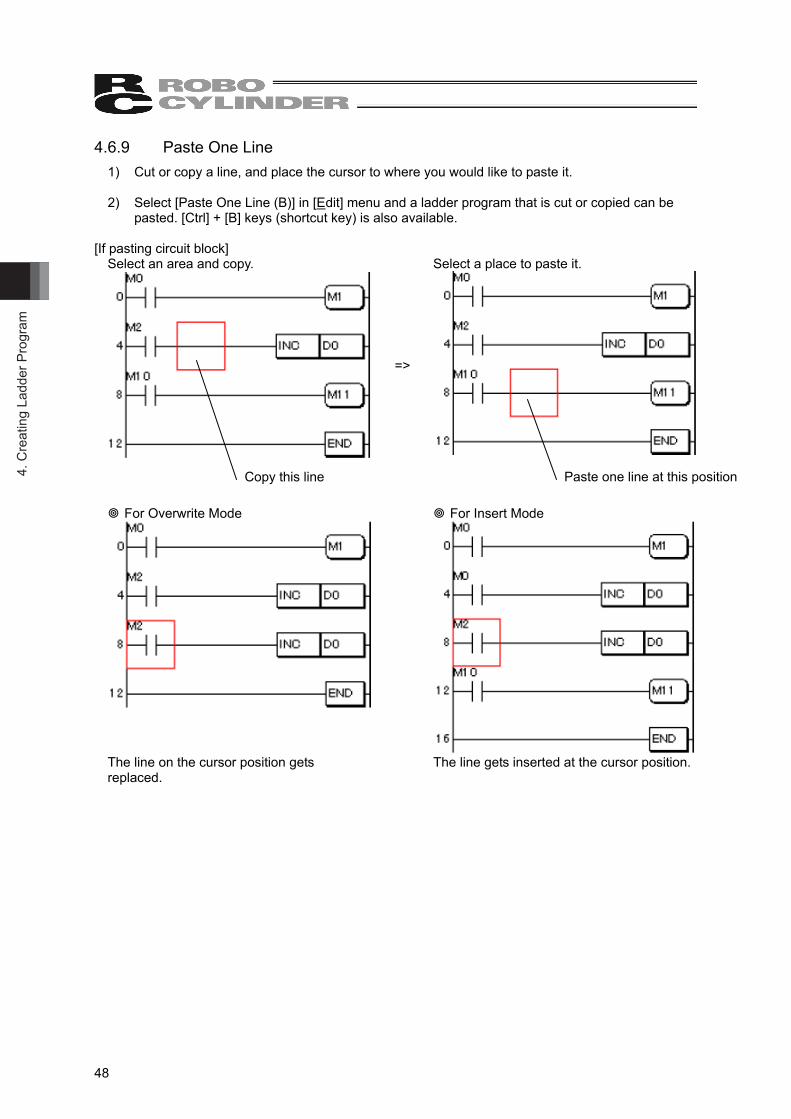
4.6.9 Paste One Line 1) Cut or copy a line, and place the cursor to where you would like to paste it. 2) Select [Paste One Line (B)] in [Edit] menu and a ladder program that is cut or copied can be
pasted. [Ctrl] + [B] keys (shortcut key) is also available. [If pasting circuit block]
Select an area and copy. Select a place to paste it.
=>
For Overwrite Mode
For Insert Mode
The line on the cursor position gets replaced. The line gets inserted at the cursor position.
Copy this line Paste one line at this position
4. Creating Ladder Program
49
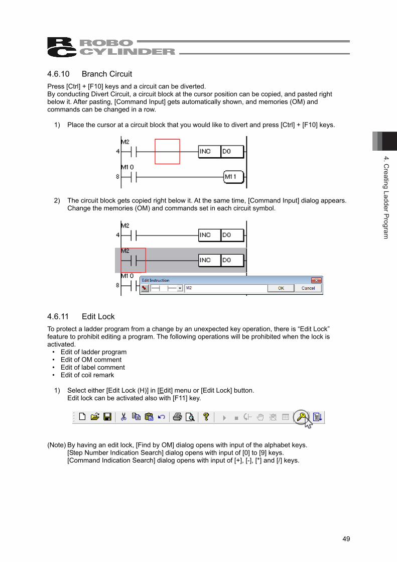
4.6.10 Branch Circuit Press [Ctrl] + [F10] keys and a circuit can be diverted. By conducting Divert Circuit, a circuit block at the cursor position can be copied, and pasted right below it. After pasting, [Command Input] gets automatically shown, and memories (OM) and commands can be changed in a row.
1) Place the cursor at a circuit block that you would like to divert and press [Ctrl] + [F10] keys.
2) The circuit block gets copied right below it. At the same time, [Command Input] dialog appears. Change the memories (OM) and commands set in each circuit symbol.
4.6.11 Edit Lock To protect a ladder program from a change by an unexpected key operation, there is “Edit Lock” feature to prohibit editing a program. The following operations will be prohibited when the lock is activated.
• Edit of ladder program • Edit of OM comment • Edit of label comment • Edit of coil remark
1) Select either [Edit Lock (H)] in [Edit] menu or [Edit Lock] button.
Edit lock can be activated also with [F11] key.
(Note) By having an edit lock, [Find by OM] dialog opens with input of the alphabet keys. [Step Number Indication Search] dialog opens with input of [0] to [9] keys. [Command Indication Search] dialog opens with input of [+], [-], [*] and [/] keys.
4. C
reat
ing
Ladd
er P
rogr
am
50
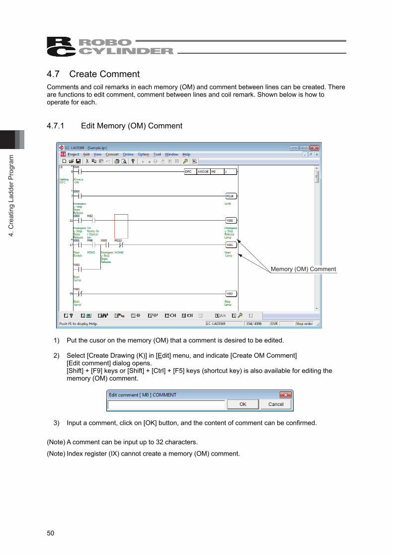
4.7 Create Comment Comments and coil remarks in each memory (OM) and comment between lines can be created. There are functions to edit comment, comment between lines and coil remark. Shown below is how to operate for each. 4.7.1 Edit Memory (OM) Comment
Memory (OM) Comment
1) Put the cusor on the memory (OM) that a comment is desired to be edited. 2) Select [Create Drawing (K)] in [Edit] menu, and indicate [Create OM Comment]
[Edit comment] dialog opens. [Shift] + [F9] keys or [Shift] + [Ctrl] + [F5] keys (shortcut key) is also available for editing the memory (OM) comment.
3) Input a comment, click on [OK] button, and the content of comment can be confirmed.
(Note) A comment can be input up to 32 characters.
(Note) Index register (IX) cannot create a memory (OM) comment.
4. Creating Ladder Program
51
4.7.2 Edit Memory (OM) Comment List
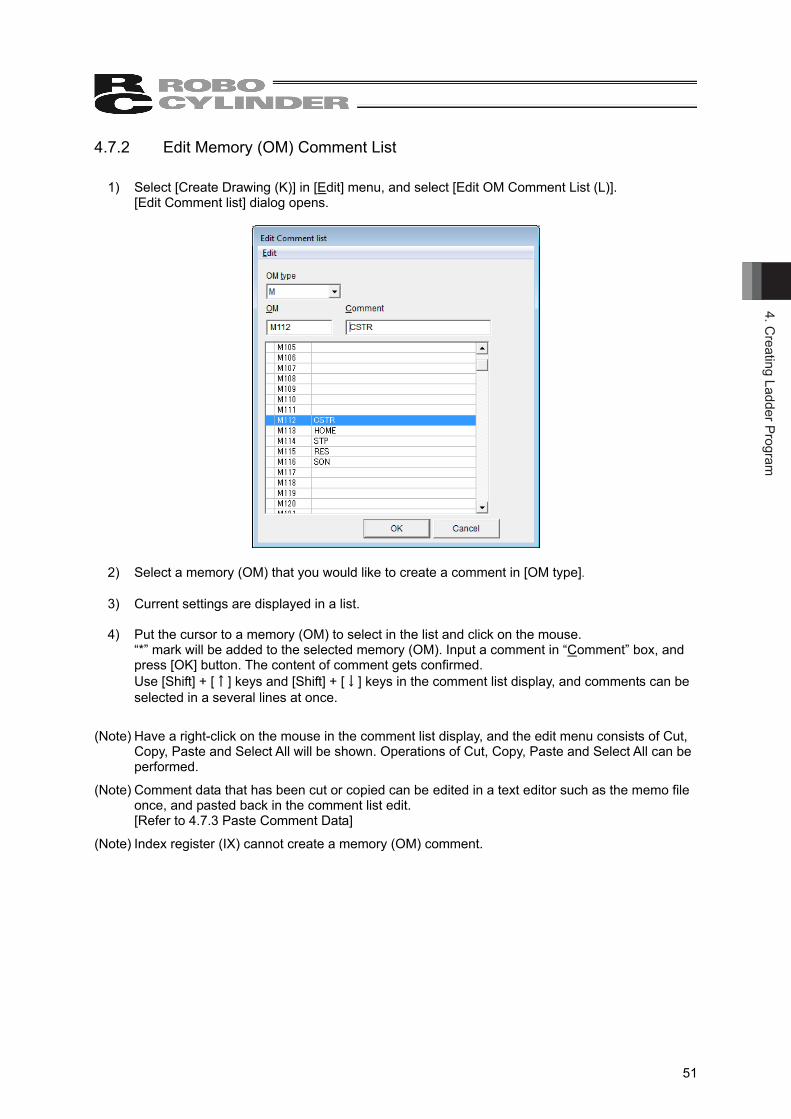
1) Select [Create Drawing (K)] in [Edit] menu, and select [Edit OM Comment List (L)]. [Edit Comment list] dialog opens.
2) Select a memory (OM) that you would like to create a comment in [OM type]. 3) Current settings are displayed in a list. 4) Put the cursor to a memory (OM) to select in the list and click on the mouse.
“*” mark will be added to the selected memory (OM). Input a comment in “Comment” box, and press [OK] button. The content of comment gets confirmed. Use [Shift] + [↑] keys and [Shift] + [↓] keys in the comment list display, and comments can be selected in a several lines at once.
(Note) Have a right-click on the mouse in the comment list display, and the edit menu consists of Cut, Copy, Paste and Select All will be shown. Operations of Cut, Copy, Paste and Select All can be performed.
(Note) Comment data that has been cut or copied can be edited in a text editor such as the memo file once, and pasted back in the comment list edit. [Refer to 4.7.3 Paste Comment Data]
(Note) Index register (IX) cannot create a memory (OM) comment.
4. C
reat
ing
Ladd
er P
rogr
am
52
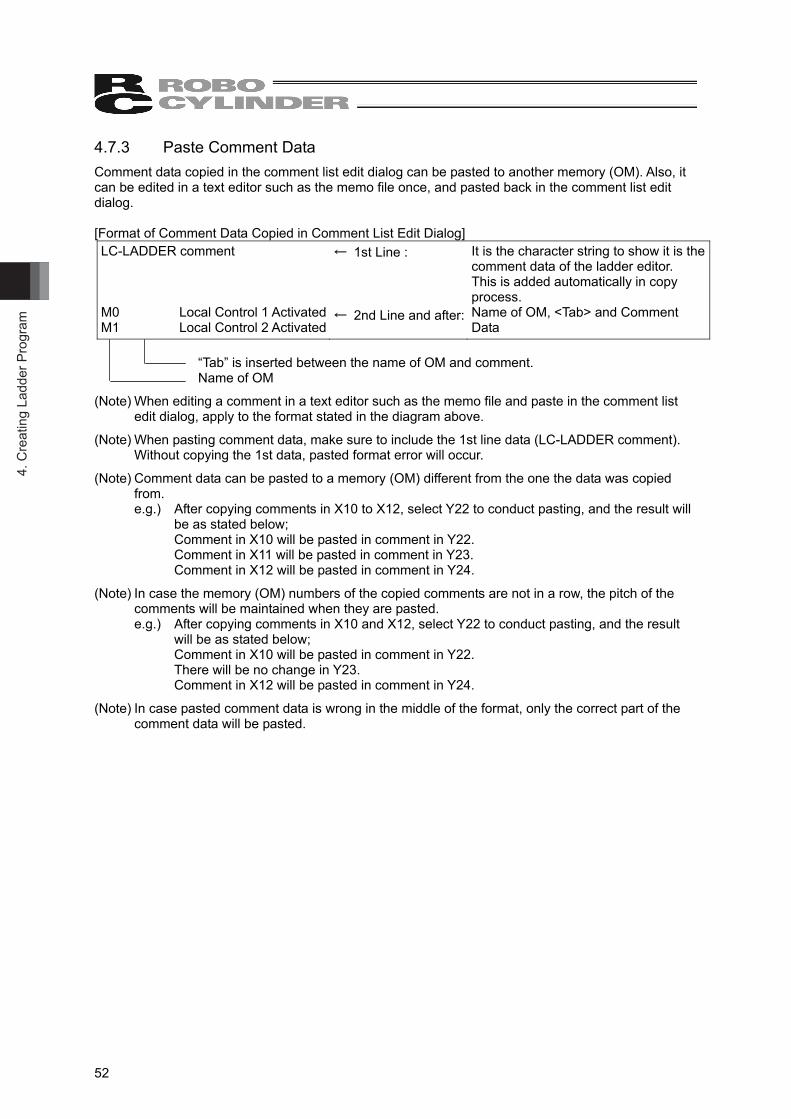
4.7.3 Paste Comment Data Comment data copied in the comment list edit dialog can be pasted to another memory (OM). Also, it can be edited in a text editor such as the memo file once, and pasted back in the comment list edit dialog. [Format of Comment Data Copied in Comment List Edit Dialog] LC-LADDER comment M0 Local Control 1 Activated M1 Local Control 2 Activated
← 1st Line : ← 2nd Line and after:
It is the character string to show it is the comment data of the ladder editor. This is added automatically in copy process. Name of OM, <Tab> and Comment Data
“Tab” is inserted between the name of OM and comment. Name of OM
(Note) When editing a comment in a text editor such as the memo file and paste in the comment list edit dialog, apply to the format stated in the diagram above.
(Note) When pasting comment data, make sure to include the 1st line data (LC-LADDER comment). Without copying the 1st data, pasted format error will occur.
(Note) Comment data can be pasted to a memory (OM) different from the one the data was copied from. e.g.) After copying comments in X10 to X12, select Y22 to conduct pasting, and the result will
be as stated below; Comment in X10 will be pasted in comment in Y22. Comment in X11 will be pasted in comment in Y23. Comment in X12 will be pasted in comment in Y24.
(Note) In case the memory (OM) numbers of the copied comments are not in a row, the pitch of the comments will be maintained when they are pasted. e.g.) After copying comments in X10 and X12, select Y22 to conduct pasting, and the result
will be as stated below; Comment in X10 will be pasted in comment in Y22. There will be no change in Y23. Comment in X12 will be pasted in comment in Y24.
(Note) In case pasted comment data is wrong in the middle of the format, only the correct part of the comment data will be pasted.
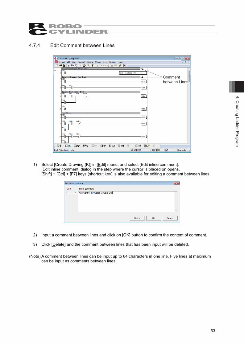
4. Creating Ladder Program
53
4.7.4 Edit Comment between Lines
Comment between Lines
1) Select [Create Drawing (K)] in [Edit] menu, and select [Edit inline comment]. [Edit inline comment] dialog in the step where the cursor is placed on opens. [Shift] + [Ctrl] + [F7] keys (shortcut key) is also available for editing a comment between lines.
2) Input a comment between lines and click on [OK] button to confirm the content of comment. 3) Click [Delete] and the comment between lines that has been input will be deleted.
(Note) A comment between lines can be input up to 64 characters in one line. Five lines at maximum can be input as comments between lines.
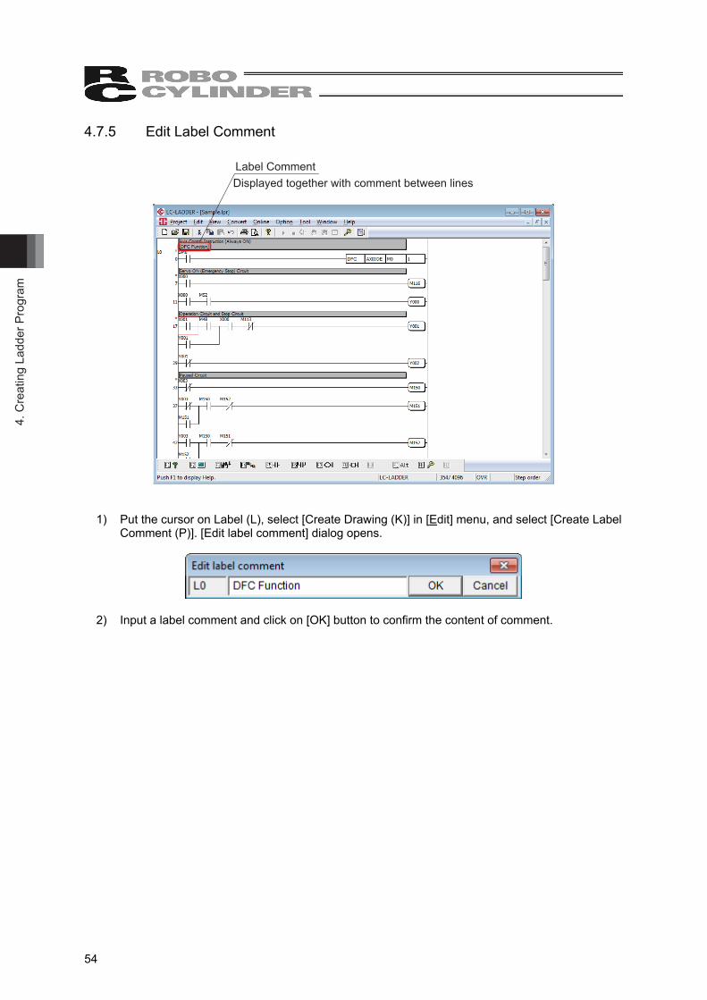
4. C
reat
ing
Ladd
er P
rogr
am
54
4.7.5 Edit Label Comment
Label CommentDisplayed together with comment between lines
1) Put the cursor on Label (L), select [Create Drawing (K)] in [Edit] menu, and select [Create Label Comment (P)]. [Edit label comment] dialog opens.
2) Input a label comment and click on [OK] button to confirm the content of comment.
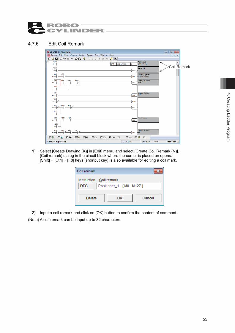
4. Creating Ladder Program
55
4.7.6 Edit Coil Remark
Coil Remark
1) Select [Create Drawing (K)] in [Edit] menu, and select [Create Coil Remark (N)]. [Coil remark] dialog in the circuit block where the cursor is placed on opens. [Shift] + [Ctrl] + [F8] keys (shortcut key) is also available for editing a coil mark.
2) Input a coil remark and click on [OK] button to confirm the content of comment.
(Note) A coil remark can be input up to 32 characters.
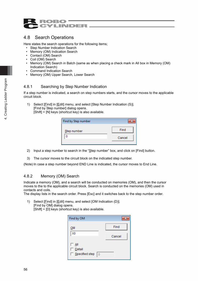
4. C
reat
ing
Ladd
er P
rogr
am
56
4.8 Search Operations Here states the search operations for the following items;
• Step Number Indication Search • Memory (OM) Indication Search • Contact (OM) Search • Coil (OM) Search • Memory (OM) Search in Batch (same as when placing a check mark in All box in Memory (OM)
Indication Search) • Command Indication Search • Memory (OM) Upper Search, Lower Search
4.8.1 Searching by Step Number Indication If a step number is indicated, a search on step numbers starts, and the cursor moves to the applicable circuit block.
1) Select [Find] in [Edit] menu, and select [Step Number Indication (S)]. [Find by Step number] dialog opens. [Shift] + [N] keys (shortcut key) is also available.
2) Input a step number to search in the “Step number” box, and click on [Find] button. 3) The cursor moves to the circuit block on the indicated step number.
(Note) In case a step number beyond END Line is indicated, the cursor moves to End Line. 4.8.2 Memory (OM) Search Indicate a memory (OM), and a search will be conducted on memories (OM), and then the cursor moves to the to the applicable circuit block. Search is conducted on the memories (OM) used in contacts and coils. The display lists in the search order. Press [Esc] and it switches back to the step number order.
1) Select [Find] in [Edit] menu, and select [OM Indication (D)]. [Find by OM] dialog opens. [Shift] + [D] keys (shortcut key) is also available.
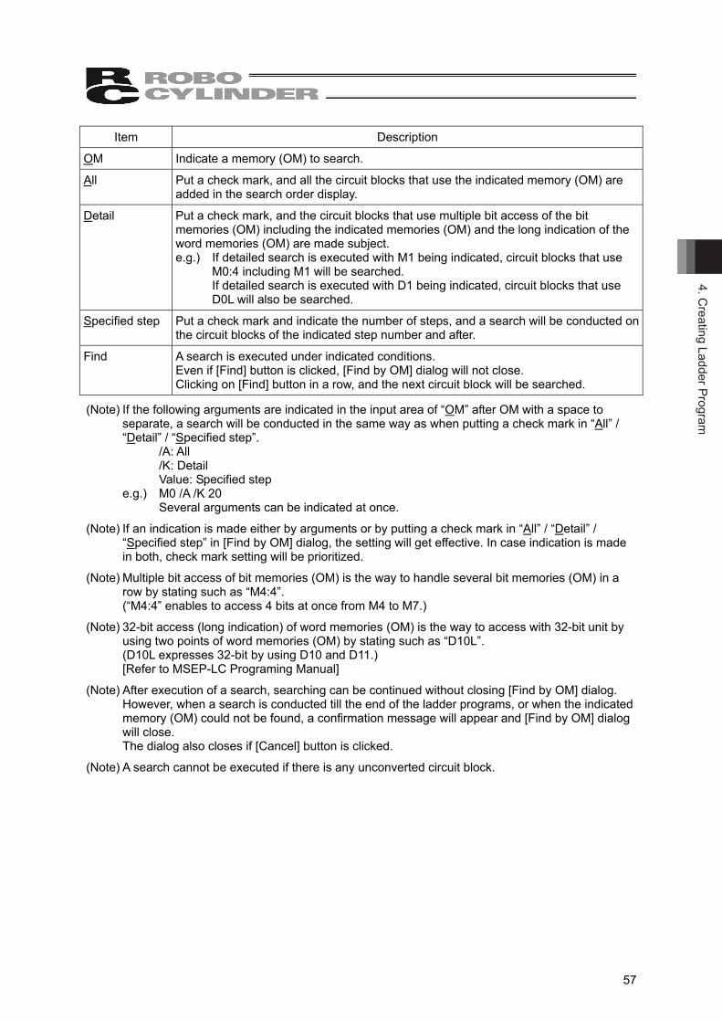
4. Creating Ladder Program
57
Item Description
OM Indicate a memory (OM) to search.
All Put a check mark, and all the circuit blocks that use the indicated memory (OM) are added in the search order display.
Detail Put a check mark, and the circuit blocks that use multiple bit access of the bit memories (OM) including the indicated memories (OM) and the long indication of the word memories (OM) are made subject. e.g.) If detailed search is executed with M1 being indicated, circuit blocks that use
M0:4 including M1 will be searched. If detailed search is executed with D1 being indicated, circuit blocks that use D0L will also be searched.
Specified step Put a check mark and indicate the number of steps, and a search will be conducted on the circuit blocks of the indicated step number and after.
Find A search is executed under indicated conditions. Even if [Find] button is clicked, [Find by OM] dialog will not close. Clicking on [Find] button in a row, and the next circuit block will be searched.
(Note) If the following arguments are indicated in the input area of “OM” after OM with a space to separate, a search will be conducted in the same way as when putting a check mark in “All” / “Detail” / “Specified step”.
/A: All /K: Detail Value: Specified step
e.g.) M0 /A /K 20 Several arguments can be indicated at once.
(Note) If an indication is made either by arguments or by putting a check mark in “All” / “Detail” / “Specified step” in [Find by OM] dialog, the setting will get effective. In case indication is made in both, check mark setting will be prioritized.
(Note) Multiple bit access of bit memories (OM) is the way to handle several bit memories (OM) in a row by stating such as “M4:4”. (“M4:4” enables to access 4 bits at once from M4 to M7.)
(Note) 32-bit access (long indication) of word memories (OM) is the way to access with 32-bit unit by using two points of word memories (OM) by stating such as “D10L”. (D10L expresses 32-bit by using D10 and D11.) [Refer to MSEP-LC Programing Manual]
(Note) After execution of a search, searching can be continued without closing [Find by OM] dialog. However, when a search is conducted till the end of the ladder programs, or when the indicated memory (OM) could not be found, a confirmation message will appear and [Find by OM] dialog will close. The dialog also closes if [Cancel] button is clicked.
(Note) A search cannot be executed if there is any unconverted circuit block.
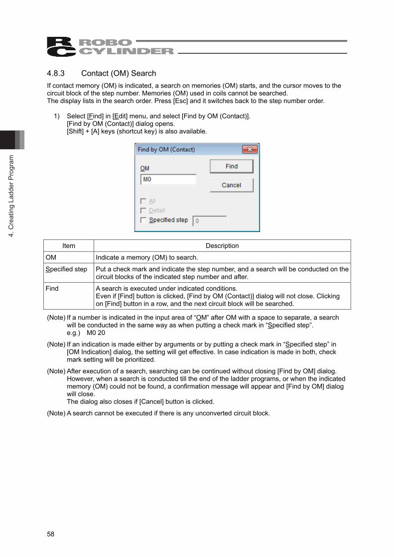
4. C
reat
ing
Ladd
er P
rogr
am
58
4.8.3 Contact (OM) Search If contact memory (OM) is indicated, a search on memories (OM) starts, and the cursor moves to the circuit block of the step number. Memories (OM) used in coils cannot be searched. The display lists in the search order. Press [Esc] and it switches back to the step number order.
1) Select [Find] in [Edit] menu, and select [Find by OM (Contact)]. [Find by OM (Contact)] dialog opens. [Shift] + [A] keys (shortcut key) is also available.
Item Description
OM Indicate a memory (OM) to search.
Specified step Put a check mark and indicate the step number, and a search will be conducted on the circuit blocks of the indicated step number and after.
Find A search is executed under indicated conditions. Even if [Find] button is clicked, [Find by OM (Contact)] dialog will not close. Clicking on [Find] button in a row, and the next circuit block will be searched.
(Note) If a number is indicated in the input area of “OM” after OM with a space to separate, a search will be conducted in the same way as when putting a check mark in “Specified step”. e.g.) M0 20
(Note) If an indication is made either by arguments or by putting a check mark in “Specified step” in [OM Indication] dialog, the setting will get effective. In case indication is made in both, check mark setting will be prioritized.
(Note) After execution of a search, searching can be continued without closing [Find by OM] dialog. However, when a search is conducted till the end of the ladder programs, or when the indicated memory (OM) could not be found, a confirmation message will appear and [Find by OM] dialog will close. The dialog also closes if [Cancel] button is clicked.
(Note) A search cannot be executed if there is any unconverted circuit block.
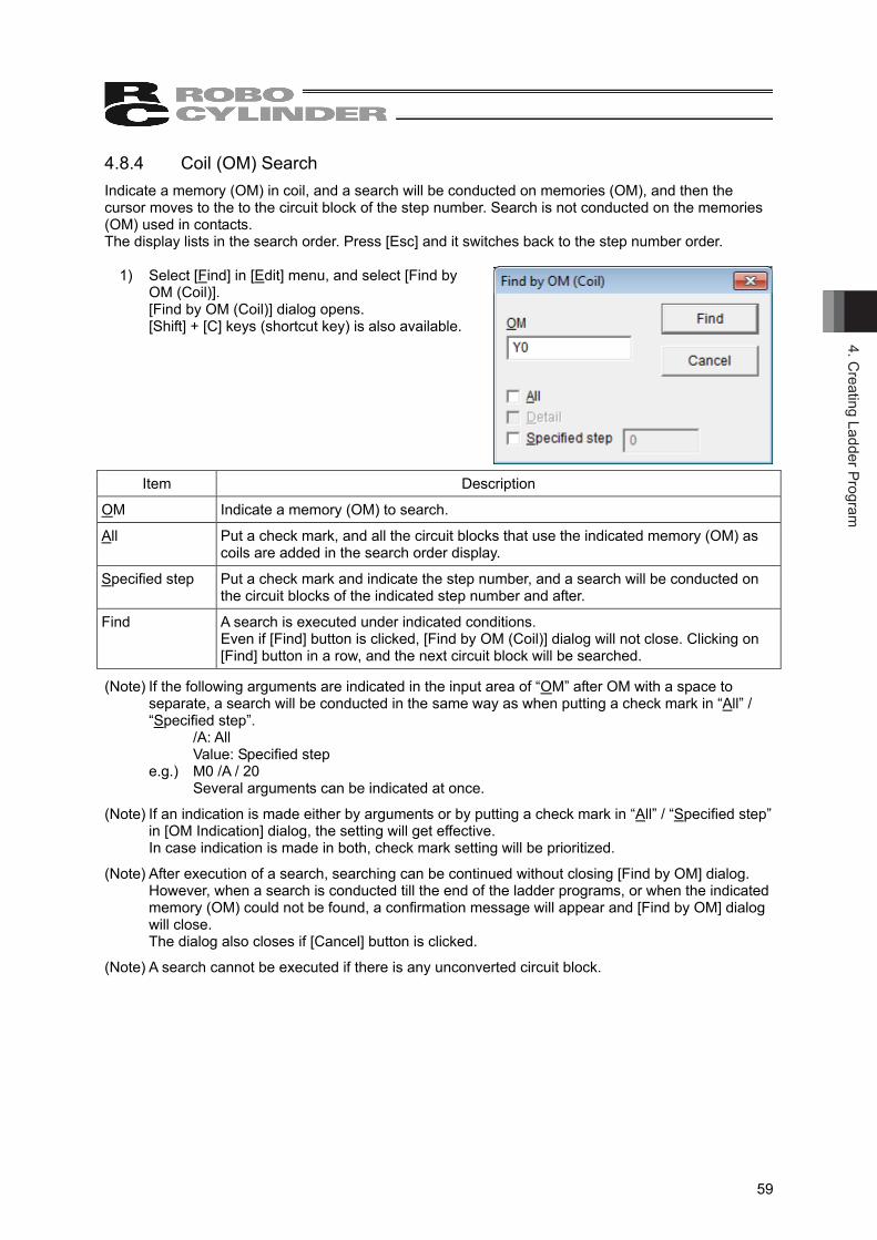
4. Creating Ladder Program
59
4.8.4 Coil (OM) Search Indicate a memory (OM) in coil, and a search will be conducted on memories (OM), and then the cursor moves to the to the circuit block of the step number. Search is not conducted on the memories (OM) used in contacts. The display lists in the search order. Press [Esc] and it switches back to the step number order.
1) Select [Find] in [Edit] menu, and select [Find by OM (Coil)]. [Find by OM (Coil)] dialog opens. [Shift] + [C] keys (shortcut key) is also available.
Item Description
OM Indicate a memory (OM) to search.
All Put a check mark, and all the circuit blocks that use the indicated memory (OM) as coils are added in the search order display.
Specified step Put a check mark and indicate the step number, and a search will be conducted on the circuit blocks of the indicated step number and after.
Find A search is executed under indicated conditions. Even if [Find] button is clicked, [Find by OM (Coil)] dialog will not close. Clicking on [Find] button in a row, and the next circuit block will be searched.
(Note) If the following arguments are indicated in the input area of “OM” after OM with a space to separate, a search will be conducted in the same way as when putting a check mark in “All” / “Specified step”. /A: All Value: Specified step e.g.) M0 /A / 20 Several arguments can be indicated at once.
(Note) If an indication is made either by arguments or by putting a check mark in “All” / “Specified step” in [OM Indication] dialog, the setting will get effective. In case indication is made in both, check mark setting will be prioritized.
(Note) After execution of a search, searching can be continued without closing [Find by OM] dialog. However, when a search is conducted till the end of the ladder programs, or when the indicated memory (OM) could not be found, a confirmation message will appear and [Find by OM] dialog will close. The dialog also closes if [Cancel] button is clicked.
(Note) A search cannot be executed if there is any unconverted circuit block.
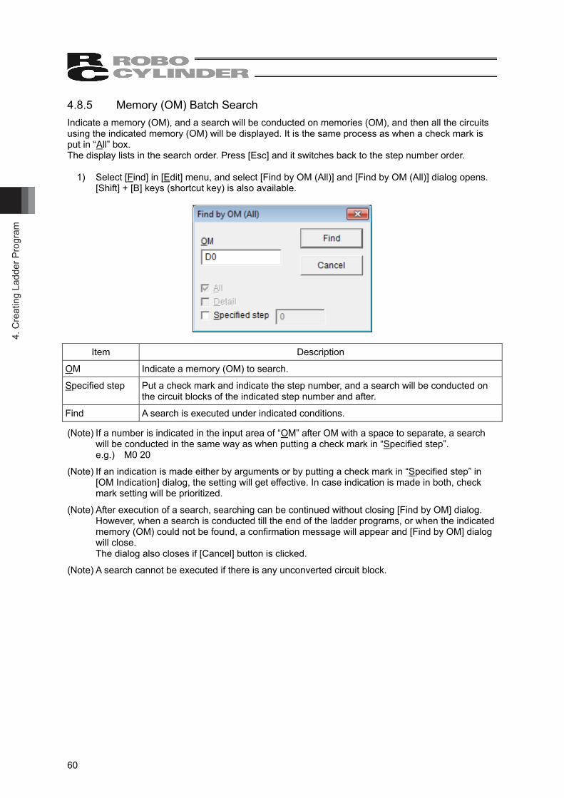
4. C
reat
ing
Ladd
er P
rogr
am
60
4.8.5 Memory (OM) Batch Search Indicate a memory (OM), and a search will be conducted on memories (OM), and then all the circuits using the indicated memory (OM) will be displayed. It is the same process as when a check mark is put in “All” box. The display lists in the search order. Press [Esc] and it switches back to the step number order.
1) Select [Find] in [Edit] menu, and select [Find by OM (All)] and [Find by OM (All)] dialog opens. [Shift] + [B] keys (shortcut key) is also available.
Item Description
OM Indicate a memory (OM) to search.
Specified step Put a check mark and indicate the step number, and a search will be conducted on the circuit blocks of the indicated step number and after.
Find A search is executed under indicated conditions.
(Note) If a number is indicated in the input area of “OM” after OM with a space to separate, a search will be conducted in the same way as when putting a check mark in “Specified step”. e.g.) M0 20
(Note) If an indication is made either by arguments or by putting a check mark in “Specified step” in [OM Indication] dialog, the setting will get effective. In case indication is made in both, check mark setting will be prioritized.
(Note) After execution of a search, searching can be continued without closing [Find by OM] dialog. However, when a search is conducted till the end of the ladder programs, or when the indicated memory (OM) could not be found, a confirmation message will appear and [Find by OM] dialog will close. The dialog also closes if [Cancel] button is clicked.
(Note) A search cannot be executed if there is any unconverted circuit block.
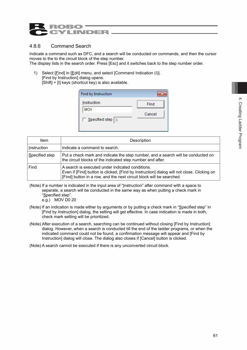
4. Creating Ladder Program
61
4.8.6 Command Search Indicate a command such as DFC, and a search will be conducted on commands, and then the cursor moves to the to the circuit block of the step number. The display lists in the search order. Press [Esc] and it switches back to the step number order.
1) Select [Find] in [Edit] menu, and select [Command Indication (I)]. [Find by Instruction] dialog opens. [Shift] + [I] keys (shortcut key) is also available.
Item Description
Instruction Indicate a command to search.
Specified step Put a check mark and indicate the step number, and a search will be conducted on the circuit blocks of the indicated step number and after.
Find A search is executed under indicated conditions. Even if [Find] button is clicked, [Find by Instruction] dialog will not close. Clicking on [Find] button in a row, and the next circuit block will be searched.
(Note) If a number is indicated in the input area of “Instruction” after command with a space to separate, a search will be conducted in the same way as when putting a check mark in “Specified step”. e.g.) MOV D0 20
(Note) If an indication is made either by arguments or by putting a check mark in “Specified step” in [Find by Instruction] dialog, the setting will get effective. In case indication is made in both, check mark setting will be prioritized.
(Note) After execution of a search, searching can be continued without closing [Find by Instruction] dialog. However, when a search is conducted till the end of the ladder programs, or when the indicated command could not be found, a confirmation message will appear and [Find by Instruction] dialog will close. The dialog also closes if [Cancel] button is clicked.
(Note) A search cannot be executed if there is any unconverted circuit block.

4. C
reat
ing
Ladd
er P
rogr
am
62
4.8.7 Memory (OM) Upper Search and Lower Search With the memory (OM) at the point where the cursor is placed as the subject to search, a search is conducted upwards or downwards. The display lists in the search order. Press [Esc] and it switches back to the step number order.
1) Place the cursor to a memory (OM) that you may want to search in a ladder program. 2) Press [Shift] + [F3] keys for “Upper Search” while [F3] key for “Lower Search”. 3) Once the indicated memory (OM) has found, circuit blocks including the found memory (OM)
will be displayed.
(Note) If any key other than [F3] or [Shift] + [F3] keys is pressed, memory (OM) in search will be cleared from the subject to search.
(Note) A search cannot be executed if there is any unconverted circuit block.
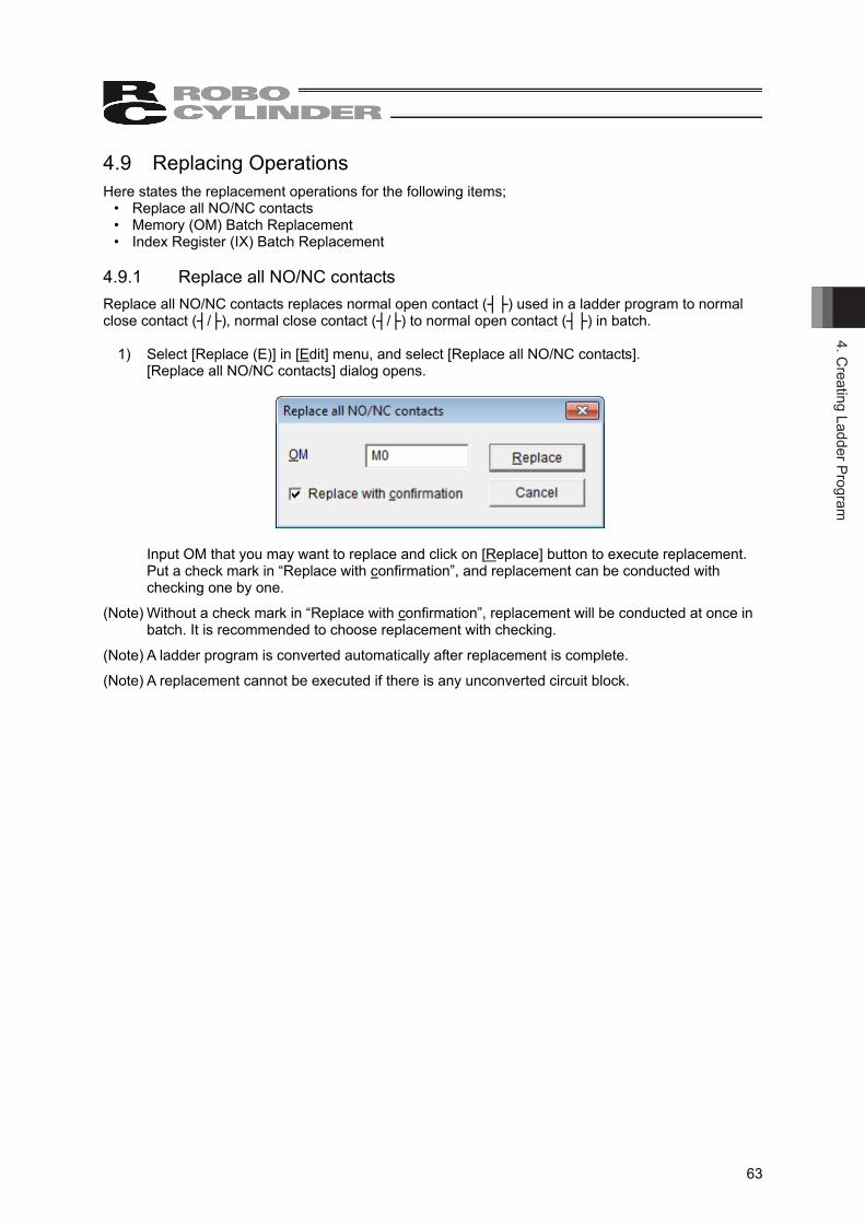
4. Creating Ladder Program
63
4.9 Replacing Operations Here states the replacement operations for the following items;
• Replace all NO/NC contacts • Memory (OM) Batch Replacement • Index Register (IX) Batch Replacement
4.9.1 Replace all NO/NC contacts Replace all NO/NC contacts replaces normal open contact (┤├) used in a ladder program to normal close contact (┤/├), normal close contact (┤/├) to normal open contact (┤├) in batch.
1) Select [Replace (E)] in [Edit] menu, and select [Replace all NO/NC contacts]. [Replace all NO/NC contacts] dialog opens.
Input OM that you may want to replace and click on [Replace] button to execute replacement. Put a check mark in “Replace with confirmation”, and replacement can be conducted with
checking one by one.
(Note) Without a check mark in “Replace with confirmation”, replacement will be conducted at once in batch. It is recommended to choose replacement with checking.
(Note) A ladder program is converted automatically after replacement is complete.
(Note) A replacement cannot be executed if there is any unconverted circuit block.
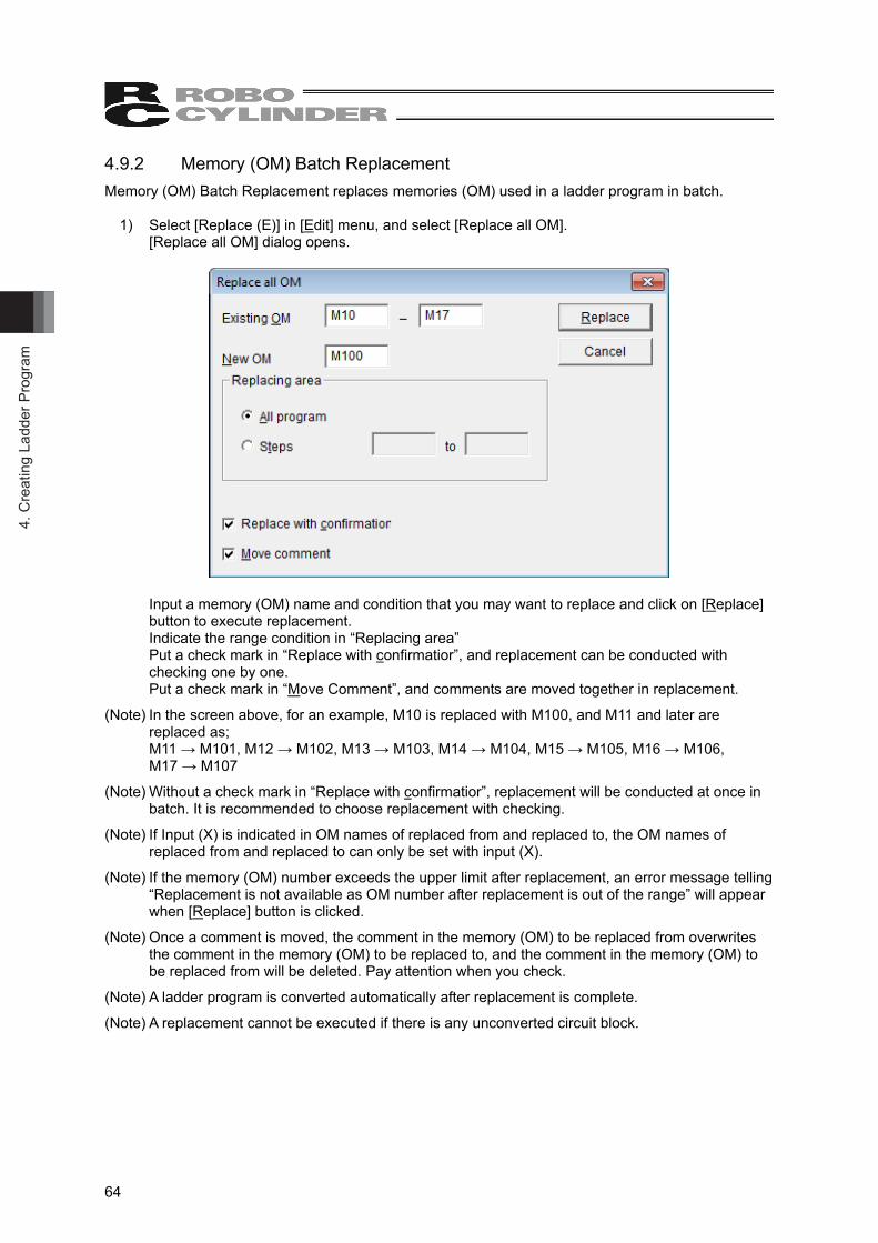
4. C
reat
ing
Ladd
er P
rogr
am
64
4.9.2 Memory (OM) Batch Replacement Memory (OM) Batch Replacement replaces memories (OM) used in a ladder program in batch.
1) Select [Replace (E)] in [Edit] menu, and select [Replace all OM]. [Replace all OM] dialog opens.
Input a memory (OM) name and condition that you may want to replace and click on [Replace] button to execute replacement. Indicate the range condition in “Replacing area” Put a check mark in “Replace with confirmatior”, and replacement can be conducted with checking one by one. Put a check mark in “Move Comment”, and comments are moved together in replacement.
(Note) In the screen above, for an example, M10 is replaced with M100, and M11 and later are replaced as; M11 → M101, M12 → M102, M13 → M103, M14 → M104, M15 → M105, M16 → M106, M17 → M107
(Note) Without a check mark in “Replace with confirmatior”, replacement will be conducted at once in batch. It is recommended to choose replacement with checking.
(Note) If Input (X) is indicated in OM names of replaced from and replaced to, the OM names of replaced from and replaced to can only be set with input (X).
(Note) If the memory (OM) number exceeds the upper limit after replacement, an error message telling “Replacement is not available as OM number after replacement is out of the range” will appear when [Replace] button is clicked.
(Note) Once a comment is moved, the comment in the memory (OM) to be replaced from overwrites the comment in the memory (OM) to be replaced to, and the comment in the memory (OM) to be replaced from will be deleted. Pay attention when you check.
(Note) A ladder program is converted automatically after replacement is complete.
(Note) A replacement cannot be executed if there is any unconverted circuit block.
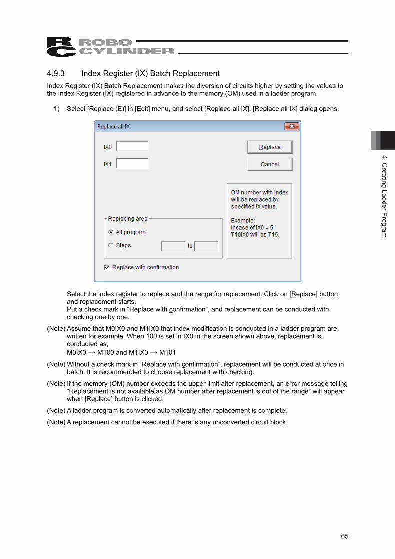
4. Creating Ladder Program
65
4.9.3 Index Register (IX) Batch Replacement Index Register (IX) Batch Replacement makes the diversion of circuits higher by setting the values to the Index Register (IX) registered in advance to the memory (OM) used in a ladder program.
1) Select [Replace (E)] in [Edit] menu, and select [Replace all IX]. [Replace all IX] dialog opens.
Select the index register to replace and the range for replacement. Click on [Replace] button and replacement starts.
Put a check mark in “Replace with confirmation”, and replacement can be conducted with checking one by one.
(Note) Assume that M0IX0 and M1IX0 that index modification is conducted in a ladder program are written for example. When 100 is set in IX0 in the screen shown above, replacement is conducted as; M0IX0 → M100 and M1IX0 → M101
(Note) Without a check mark in “Replace with confirmation”, replacement will be conducted at once in batch. It is recommended to choose replacement with checking.
(Note) If the memory (OM) number exceeds the upper limit after replacement, an error message telling “Replacement is not available as OM number after replacement is out of the range” will appear when [Replace] button is clicked.
(Note) A ladder program is converted automatically after replacement is complete.
(Note) A replacement cannot be executed if there is any unconverted circuit block.
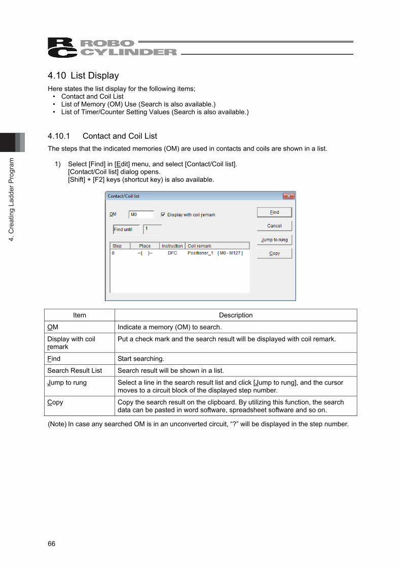
4. C
reat
ing
Ladd
er P
rogr
am
66
4.10 List Display Here states the list display for the following items;
• Contact and Coil List • List of Memory (OM) Use (Search is also available.) • List of Timer/Counter Setting Values (Search is also available.)
4.10.1 Contact and Coil List The steps that the indicated memories (OM) are used in contacts and coils are shown in a list.
1) Select [Find] in [Edit] menu, and select [Contact/Coil list]. [Contact/Coil list] dialog opens. [Shift] + [F2] keys (shortcut key) is also available.
Item Description
OM Indicate a memory (OM) to search.
Display with coil remark
Put a check mark and the search result will be displayed with coil remark.
Find Start searching.
Search Result List Search result will be shown in a list.
Jump to rung Select a line in the search result list and click [Jump to rung], and the cursor moves to a circuit block of the displayed step number.
Copy Copy the search result on the clipboard. By utilizing this function, the search data can be pasted in word software, spreadsheet software and so on.
(Note) In case any searched OM is in an unconverted circuit, “?” will be displayed in the step number.
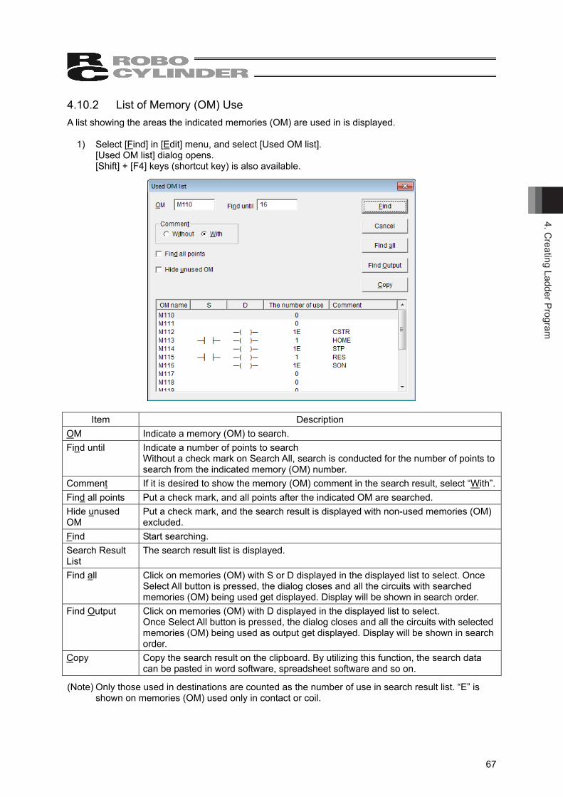
4. Creating Ladder Program
67
4.10.2 List of Memory (OM) Use A list showing the areas the indicated memories (OM) are used in is displayed.
1) Select [Find] in [Edit] menu, and select [Used OM list]. [Used OM list] dialog opens. [Shift] + [F4] keys (shortcut key) is also available.
Item Description OM Indicate a memory (OM) to search. Find until Indicate a number of points to search
Without a check mark on Search All, search is conducted for the number of points to search from the indicated memory (OM) number.
Comment If it is desired to show the memory (OM) comment in the search result, select “With”.Find all points Put a check mark, and all points after the indicated OM are searched. Hide unused OM
Put a check mark, and the search result is displayed with non-used memories (OM) excluded.
Find Start searching. Search Result List
The search result list is displayed.
Find all Click on memories (OM) with S or D displayed in the displayed list to select. Once Select All button is pressed, the dialog closes and all the circuits with searched memories (OM) being used get displayed. Display will be shown in search order.
Find Output Click on memories (OM) with D displayed in the displayed list to select. Once Select All button is pressed, the dialog closes and all the circuits with selected memories (OM) being used as output get displayed. Display will be shown in search order.
Copy Copy the search result on the clipboard. By utilizing this function, the search data can be pasted in word software, spreadsheet software and so on.
(Note) Only those used in destinations are counted as the number of use in search result list. “E” is shown on memories (OM) used only in contact or coil.
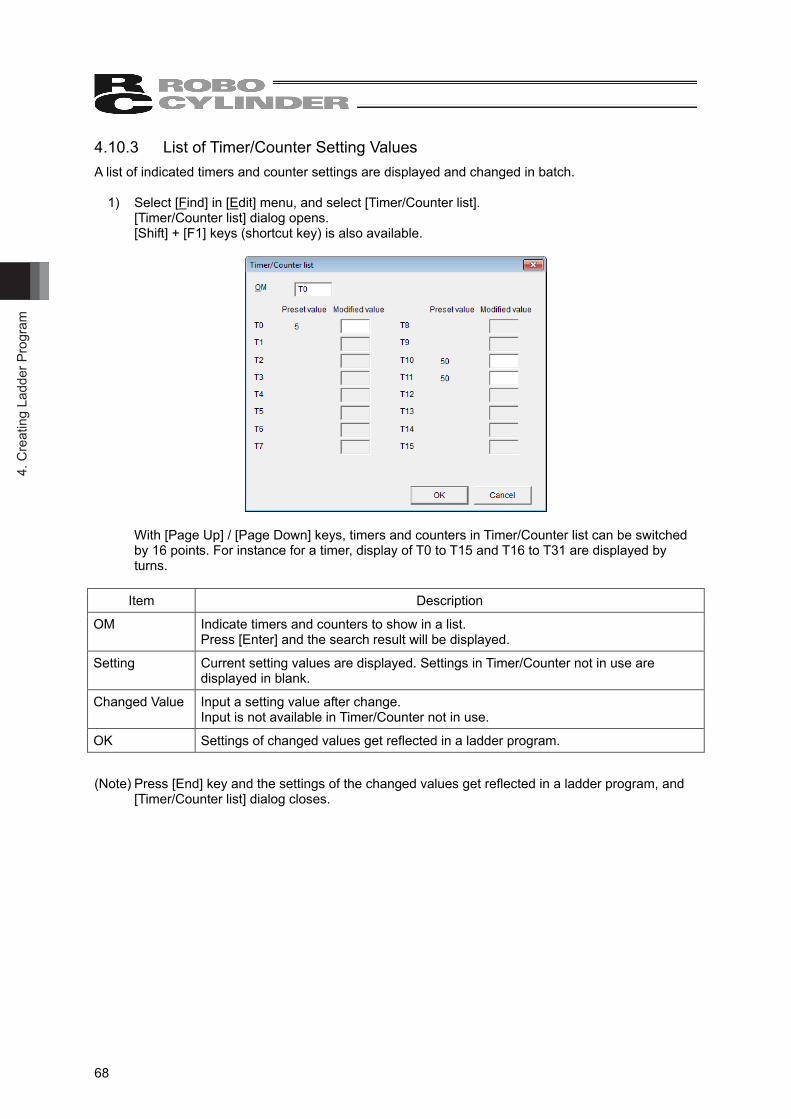
4. C
reat
ing
Ladd
er P
rogr
am
68
4.10.3 List of Timer/Counter Setting Values A list of indicated timers and counter settings are displayed and changed in batch.
1) Select [Find] in [Edit] menu, and select [Timer/Counter list]. [Timer/Counter list] dialog opens. [Shift] + [F1] keys (shortcut key) is also available.
With [Page Up] / [Page Down] keys, timers and counters in Timer/Counter list can be switched by 16 points. For instance for a timer, display of T0 to T15 and T16 to T31 are displayed by turns.
Item Description
OM Indicate timers and counters to show in a list. Press [Enter] and the search result will be displayed.
Setting Current setting values are displayed. Settings in Timer/Counter not in use are displayed in blank.
Changed Value Input a setting value after change. Input is not available in Timer/Counter not in use.
OK Settings of changed values get reflected in a ladder program.
(Note) Press [End] key and the settings of the changed values get reflected in a ladder program, and [Timer/Counter list] dialog closes.
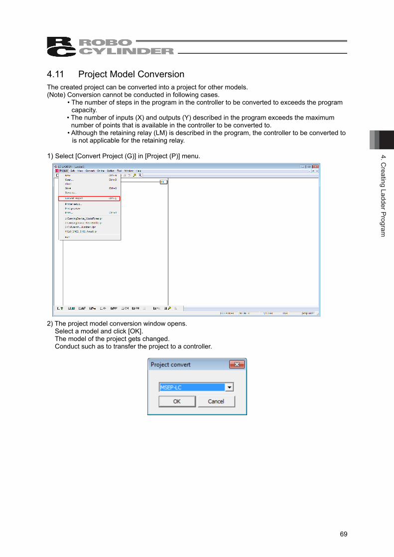
4. Creating Ladder Program
69
4.11 Project Model Conversion The created project can be converted into a project for other models. (Note) Conversion cannot be conducted in following cases. • The number of steps in the program in the controller to be converted to exceeds the program
capacity. • The number of inputs (X) and outputs (Y) described in the program exceeds the maximum
number of points that is available in the controller to be converted to. • Although the retaining relay (LM) is described in the program, the controller to be converted to
is not applicable for the retaining relay. 1) Select [Convert Project (G)] in [Project (P)] menu. 2) The project model conversion window opens.
Select a model and click [OK]. The model of the project gets changed. Conduct such as to transfer the project to a controller.
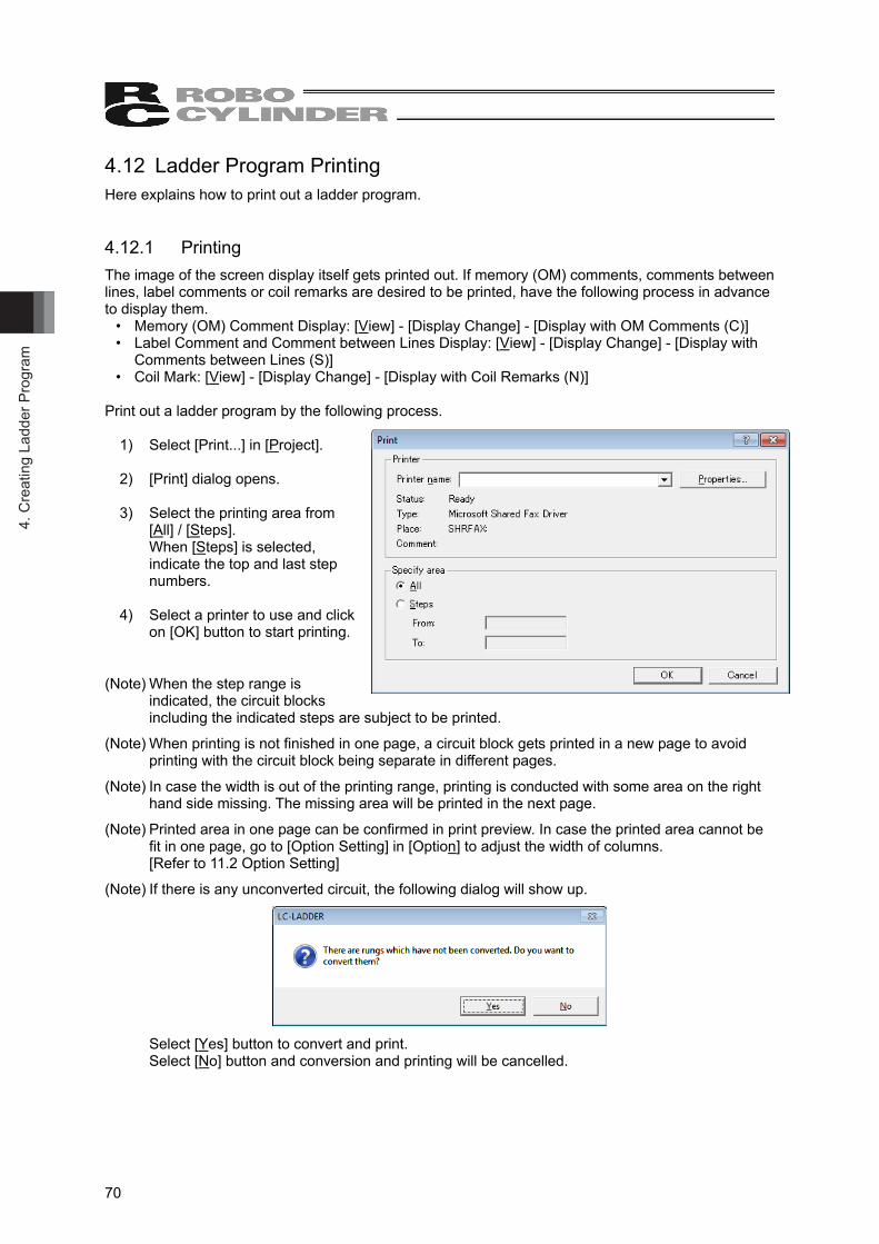
4. C
reat
ing
Ladd
er P
rogr
am
70
4.12 Ladder Program Printing Here explains how to print out a ladder program. 4.12.1 Printing The image of the screen display itself gets printed out. If memory (OM) comments, comments between lines, label comments or coil remarks are desired to be printed, have the following process in advance to display them.
• Memory (OM) Comment Display: [View] - [Display Change] - [Display with OM Comments (C)] • Label Comment and Comment between Lines Display: [View] - [Display Change] - [Display with
Comments between Lines (S)] • Coil Mark: [View] - [Display Change] - [Display with Coil Remarks (N)]
Print out a ladder program by the following process.
1) Select [Print...] in [Project]. 2) [Print] dialog opens. 3) Select the printing area from
[All] / [Steps]. When [Steps] is selected, indicate the top and last step numbers.
4) Select a printer to use and click
on [OK] button to start printing.
(Note) When the step range is indicated, the circuit blocks including the indicated steps are subject to be printed.
(Note) When printing is not finished in one page, a circuit block gets printed in a new page to avoid printing with the circuit block being separate in different pages.
(Note) In case the width is out of the printing range, printing is conducted with some area on the right hand side missing. The missing area will be printed in the next page.
(Note) Printed area in one page can be confirmed in print preview. In case the printed area cannot be fit in one page, go to [Option Setting] in [Option] to adjust the width of columns. [Refer to 11.2 Option Setting]
(Note) If there is any unconverted circuit, the following dialog will show up.
Select [Yes] button to convert and print.
Select [No] button and conversion and printing will be cancelled.
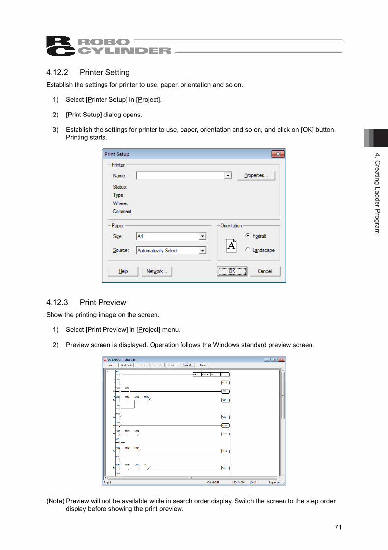
4. Creating Ladder Program
71
4.12.2 Printer Setting Establish the settings for printer to use, paper, orientation and so on.
1) Select [Printer Setup] in [Project]. 2) [Print Setup] dialog opens. 3) Establish the settings for printer to use, paper, orientation and so on, and click on [OK] button.
Printing starts.
4.12.3 Print Preview Show the printing image on the screen.
1) Select [Print Preview] in [Project] menu. 2) Preview screen is displayed. Operation follows the Windows standard preview screen.
(Note) Preview will not be available while in search order display. Switch the screen to the step order display before showing the print preview.
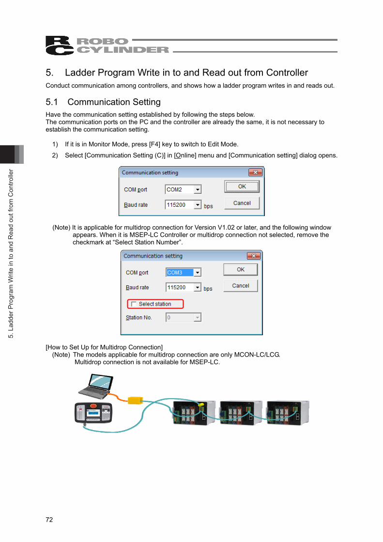
5. L
adde
r Pro
gram
Writ
e in
to a
nd R
ead
out f
rom
Con
trolle
r
72
5. Ladder Program Write in to and Read out from Controller Conduct communication among controllers, and shows how a ladder program writes in and reads out. 5.1 Communication Setting Have the communication setting established by following the steps below. The communication ports on the PC and the controller are already the same, it is not necessary to establish the communication setting.
1) If it is in Monitor Mode, press [F4] key to switch to Edit Mode.
2) Select [Communication Setting (C)] in [Online] menu and [Communication setting] dialog opens.
(Note) It is applicable for multidrop connection for Version V1.02 or later, and the following window appears. When it is MSEP-LC Controller or multidrop connection not selected, remove the checkmark at “Select Station Number”.
[How to Set Up for Multidrop Connection] (Note) The models applicable for multidrop connection are only MCON-LC/LCG.
Multidrop connection is not available for MSEP-LC.
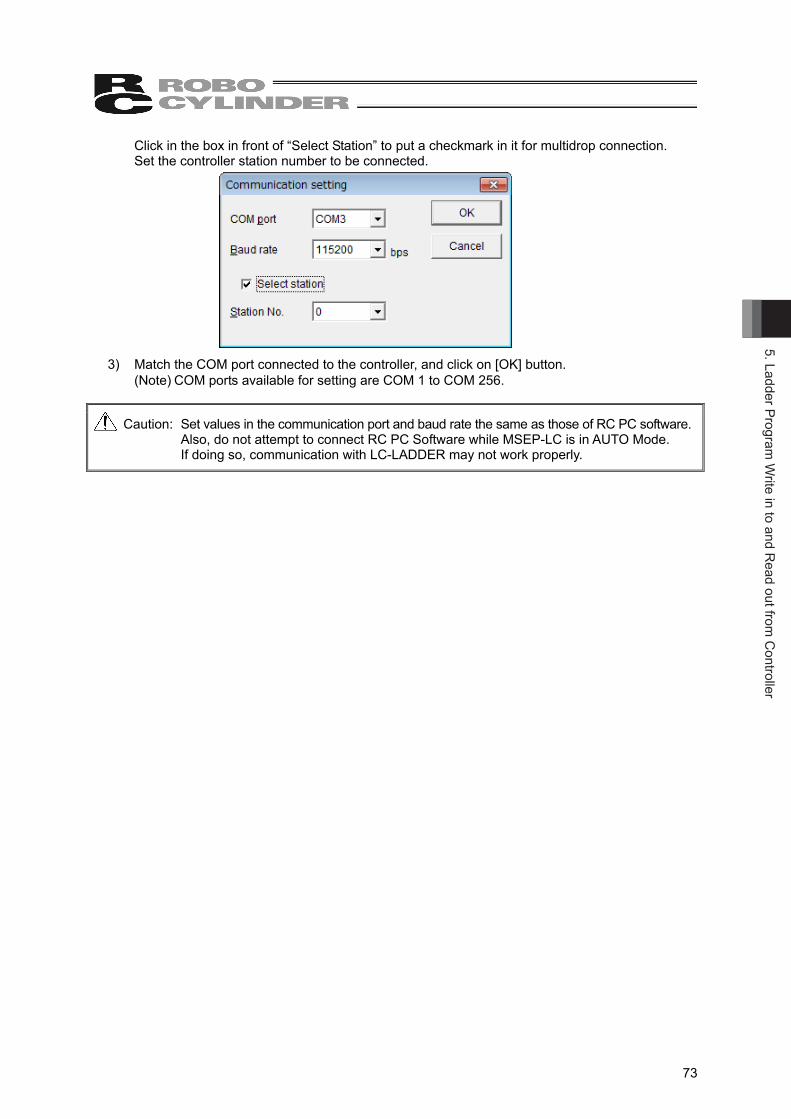
5. Ladder Program W
rite in to and Read out from
Controller
73
Click in the box in front of “Select Station” to put a checkmark in it for multidrop connection. Set the controller station number to be connected.
3) Match the COM port connected to the controller, and click on [OK] button. (Note) COM ports available for setting are COM 1 to COM 256.
Caution: Set values in the communication port and baud rate the same as those of RC PC software.Also, do not attempt to connect RC PC Software while MSEP-LC is in AUTO Mode. If doing so, communication with LC-LADDER may not work properly.
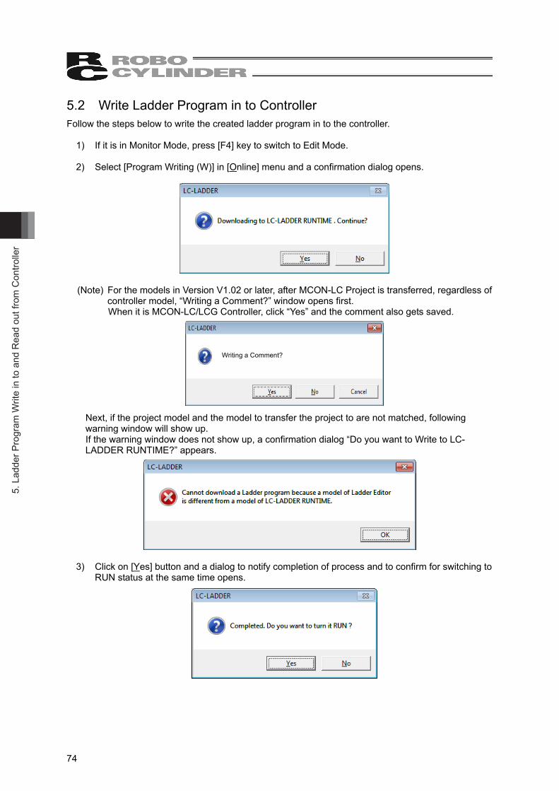
5. L
adde
r Pro
gram
Writ
e in
to a
nd R
ead
out f
rom
Con
trolle
r
74
5.2 Write Ladder Program in to Controller Follow the steps below to write the created ladder program in to the controller.
1) If it is in Monitor Mode, press [F4] key to switch to Edit Mode. 2) Select [Program Writing (W)] in [Online] menu and a confirmation dialog opens.
(Note) For the models in Version V1.02 or later, after MCON-LC Project is transferred, regardless of
controller model, “Writing a Comment?” window opens first. When it is MCON-LC/LCG Controller, click “Yes” and the comment also gets saved.
Writing a Comment?
Next, if the project model and the model to transfer the project to are not matched, following warning window will show up.
If the warning window does not show up, a confirmation dialog “Do you want to Write to LC-LADDER RUNTIME?” appears.
3) Click on [Yes] button and a dialog to notify completion of process and to confirm for switching to
RUN status at the same time opens.
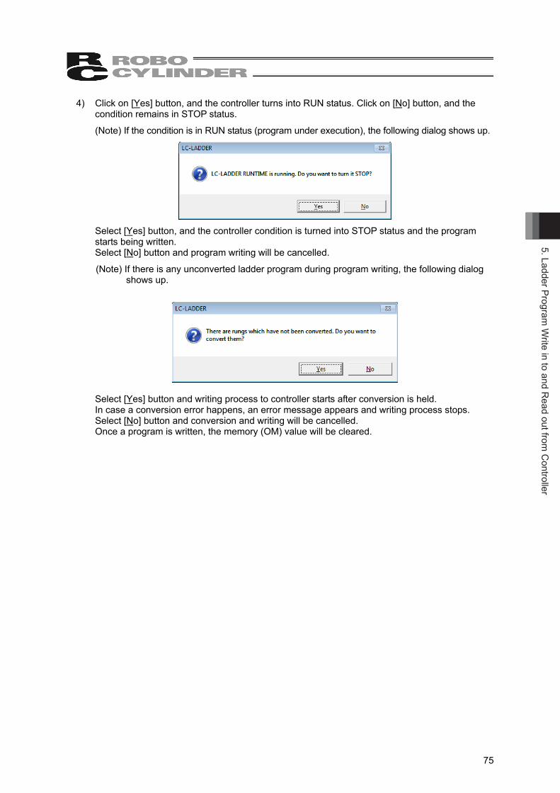
5. Ladder Program W
rite in to and Read out from
Controller
75
4) Click on [Yes] button, and the controller turns into RUN status. Click on [No] button, and the condition remains in STOP status.
(Note) If the condition is in RUN status (program under execution), the following dialog shows up.
Select [Yes] button, and the controller condition is turned into STOP status and the program
starts being written. Select [No] button and program writing will be cancelled.
(Note) If there is any unconverted ladder program during program writing, the following dialog shows up.
Select [Yes] button and writing process to controller starts after conversion is held. In case a conversion error happens, an error message appears and writing process stops. Select [No] button and conversion and writing will be cancelled. Once a program is written, the memory (OM) value will be cleared.
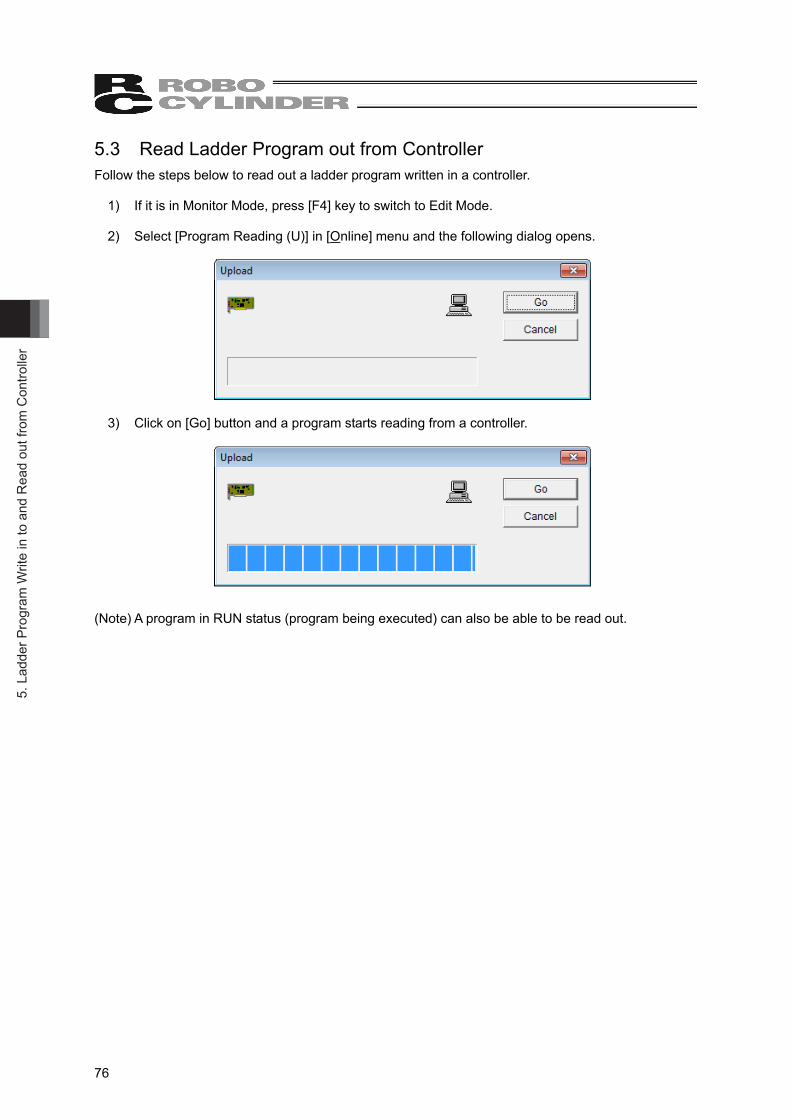
5. L
adde
r Pro
gram
Writ
e in
to a
nd R
ead
out f
rom
Con
trolle
r
76
5.3 Read Ladder Program out from Controller Follow the steps below to read out a ladder program written in a controller.
1) If it is in Monitor Mode, press [F4] key to switch to Edit Mode. 2) Select [Program Reading (U)] in [Online] menu and the following dialog opens.
3) Click on [Go] button and a program starts reading from a controller.
(Note) A program in RUN status (program being executed) can also be able to be read out.
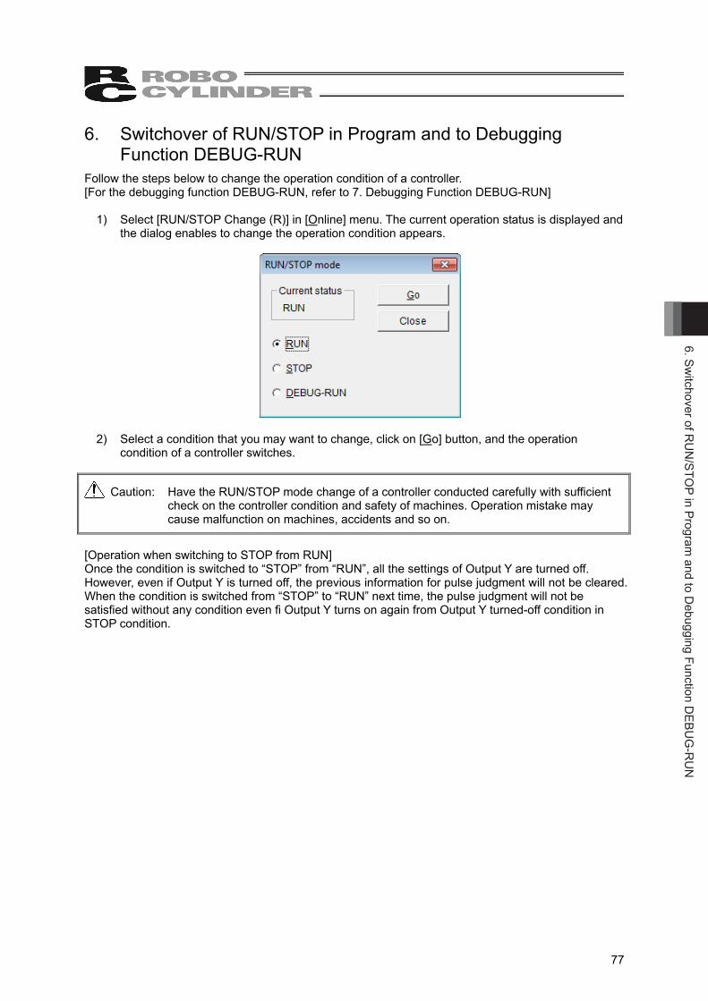
6. Switchover of R
UN
/STOP in Program
and to Debugging Function D
EBUG
-RU
N
77
6. Switchover of RUN/STOP in Program and to Debugging Function DEBUG-RUN
Follow the steps below to change the operation condition of a controller. [For the debugging function DEBUG-RUN, refer to 7. Debugging Function DEBUG-RUN]
1) Select [RUN/STOP Change (R)] in [Online] menu. The current operation status is displayed and the dialog enables to change the operation condition appears.
2) Select a condition that you may want to change, click on [Go] button, and the operation
condition of a controller switches.
Caution: Have the RUN/STOP mode change of a controller conducted carefully with sufficient check on the controller condition and safety of machines. Operation mistake may cause malfunction on machines, accidents and so on.
[Operation when switching to STOP from RUN] Once the condition is switched to “STOP” from “RUN”, all the settings of Output Y are turned off. However, even if Output Y is turned off, the previous information for pulse judgment will not be cleared. When the condition is switched from “STOP” to “RUN” next time, the pulse judgment will not be satisfied without any condition even fi Output Y turns on again from Output Y turned-off condition in STOP condition.
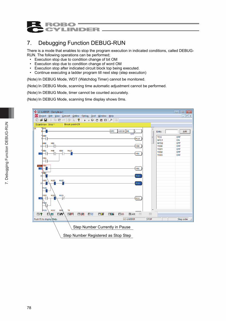
7. D
ebug
ging
Fun
ctio
n D
EBU
G-R
UN
78
7. Debugging Function DEBUG-RUN There is a mode that enables to stop the program execution in indicated conditions, called DEBUG-RUN. The following operations can be performed;
• Execution stop due to condition change of bit OM • Execution stop due to condition change of word OM • Execution stop after indicated circuit block top being executed. • Continue executing a ladder program till next step (step execution)
(Note) In DEBUG Mode, WDT (Watchdog Timer) cannot be monitored.
(Note) In DEBUG Mode, scanning time automatic adjustment cannot be performed.
(Note) In DEBUG Mode, timer cannot be counted accurately.
(Note) In DEBUG Mode, scanning time display shows 0ms.
Step Number Currently in Pause
Step Number Registered as Stop Step
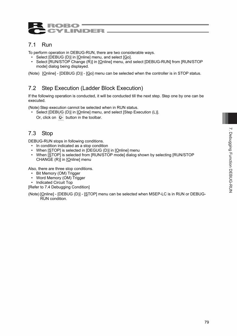
7. Debugging Function D
EBUG
-RU
N
79
7.1 Run To perform operation in DEBUG-RUN, there are two considerable ways.
• Select [DEBUG (D)] in [Online] menu, and select [Go]. • Select [RUN/STOP Change (R)] in [Online] menu, and select [DEBUG-RUN] from [RUN/STOP
mode] dialog being displayed.
(Note) [Online] - [DEBUG (D)] - [Go] menu can be selected when the controller is in STOP status. 7.2 Step Execution (Ladder Block Execution) If the following operation is conducted, it will be conducted till the next step. Step one by one can be executed.
(Note) Step execution cannot be selected when in RUN status. • Select [DEBUG (D)] in [Online] menu, and select [Step Execution (L)].
Or, click on button in the toolbar. 7.3 Stop DEBUG-RUN stops in following conditions.
• In condition indicated as a stop condition • When [STOP] is selected in [DEGUG (D)] in [Online] menu • When [STOP] is selected from [RUN/STOP mode] dialog shown by selecting [RUN/STOP
CHANGE (R)] in [Online] menu Also, there are three stop conditions.
• Bit Memory (OM) Trigger • Word Memory (OM) Trigger • Indicated Circuit Top
[Refer to 7.4 Debugging Condition]
(Note) [Online] - [DEBUG (D)] - [STOP] menu can be selected when MSEP-LC is in RUN or DEBUG-RUN condition.
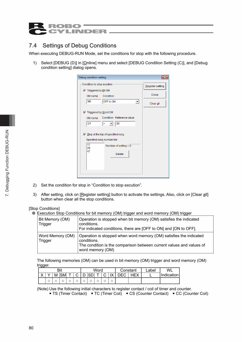
7. D
ebug
ging
Fun
ctio
n D
EBU
G-R
UN
80
7.4 Settings of Debug Conditions When executing DEBUG-RUN Mode, set the conditions for stop with the following procedure.
1) Select [DEBUG (D)] in [Online] menu and select [DEBUG Condition Setting (C)], and [Debug condition setting] dialog opens.
2) Set the condition for stop in “Condition to stop excution”. 3) After setting, click on [Register setting] button to activate the settings. Also, click on [Clear all]
button when clear all the stop conditions. [Stop Conditions]
Execution Stop Conditions for bit memory (OM) trigger and word memory (OM) trigger Bit Memory (OM) Trigger
Operation is stopped when bit memory (OM) satisfies the indicated conditions. For indicated conditions, there are [OFF to ON] and [ON to OFF].
Word Memory (OM) Trigger
Operation is stopped when word memory (OM) satisfies the indicated conditions. The condition is the comparison between current values and values of word memory (OM)
The following memories (OM) can be used in bit memory (OM) trigger and word memory (OM) trigger.
Bit Word Constant Label X Y M SM T C D SD T C IX DEC HEX L
WL Indication
○ ○ ○ ○ ○ ○ ○ ○ ○ ○
(Note) Use the following initial characters to register contact / coil of timer and counter. TS (Timer Contact) TC (Timer Coil) CS (Counter Contact) CC (Counter Coil)

7. Debugging Function D
EBUG
-RU
N
81
Stop at the top of specified rung An operation gets stopped if the step number of a circuit block that the step number is registered is executed. Follow the steps below for registration and cancel of stop step.
[Registration and Cancel of Stop Step] Have the stop step to make in execution stop condition registered or cancelled with the following steps.
• Put the cursor on a circuit block that you may want to register, select [DEBUG (D)] in [Online] menu and select [Establish / Cancel Stop Step Setting (B)]. The background color of a step number turns into blue once it is registered. Select [Establish / Cancel Stop Step Setting (B)] again to cancel the setting. The blue in background of a step number gets turned off.
• Double-click on a step number of a circuit block that you may want to register. The background color of a step number turns into blue once it is registered. Double-click on it again, and it is cancelled. The blue in background of a step number gets turned off.
• Select a step that you may want to cancel from [Specified rung number list] in [Debug Condition setting] dialog, and click on [Delete] button.
• Select [DEBUG (D)] in [Online] menu, and select [All Clear Stop Step]. All the stop steps will be cancelled in this case.
(Note) Registration of stop steps can be established at 16 points at maximum.
(Note) When the cursor is not placed on the top of a circuit block and stop step is established, it will automatically be set on the top of a circuit.
(Note) Registration of stop step can be held only when in STOP / DEBUG-RUN condition.
(Note) All the stop steps will automatically be cleared when the condition turns into RUN from STOP/DEBUG-RUN.
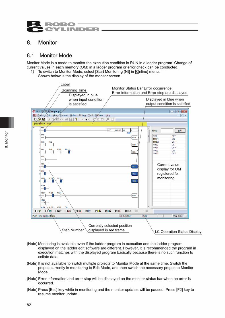
8. M
onito
r
82
8. Monitor 8.1 Monitor Mode Monitor Mode is a mode to monitor the execution condition in RUN in a ladder program. Change of current values in each memory (OM) in a ladder program or error check can be conducted.
1) To switch to Monitor Mode, select [Start Monitoring (N)] in [Online] menu. Shown below is the display of the monitor screen.
Label
Step Number
Scanning TimeDisplayed in blue when input condition is satisfied
Monitor Status Bar Error occurrence, Error information and Error step are displayed
Displayed in blue when output condition is satisfied
Current value display for OM registered for monitoring
LC Operation Status DisplayCurrently selected position displayed in red frame
(Note) Monitoring is available even if the ladder program in execution and the ladder program displayed on the ladder edit software are different. However, it is recommended the program in execution matches with the displayed program basically because there is no such function to collate data.
(Note) It is not available to switch multiple projects to Monitor Mode at the same time. Switch the project currently in monitoring to Edit Mode, and then switch the necessary project to Monitor Mode.
(Note) Error information and error step will be displayed on the monitor status bar when an error is occurred.
(Note) Press [Esc] key while in monitoring and the monitor updates will be paused. Press [F2] key to resume monitor update.
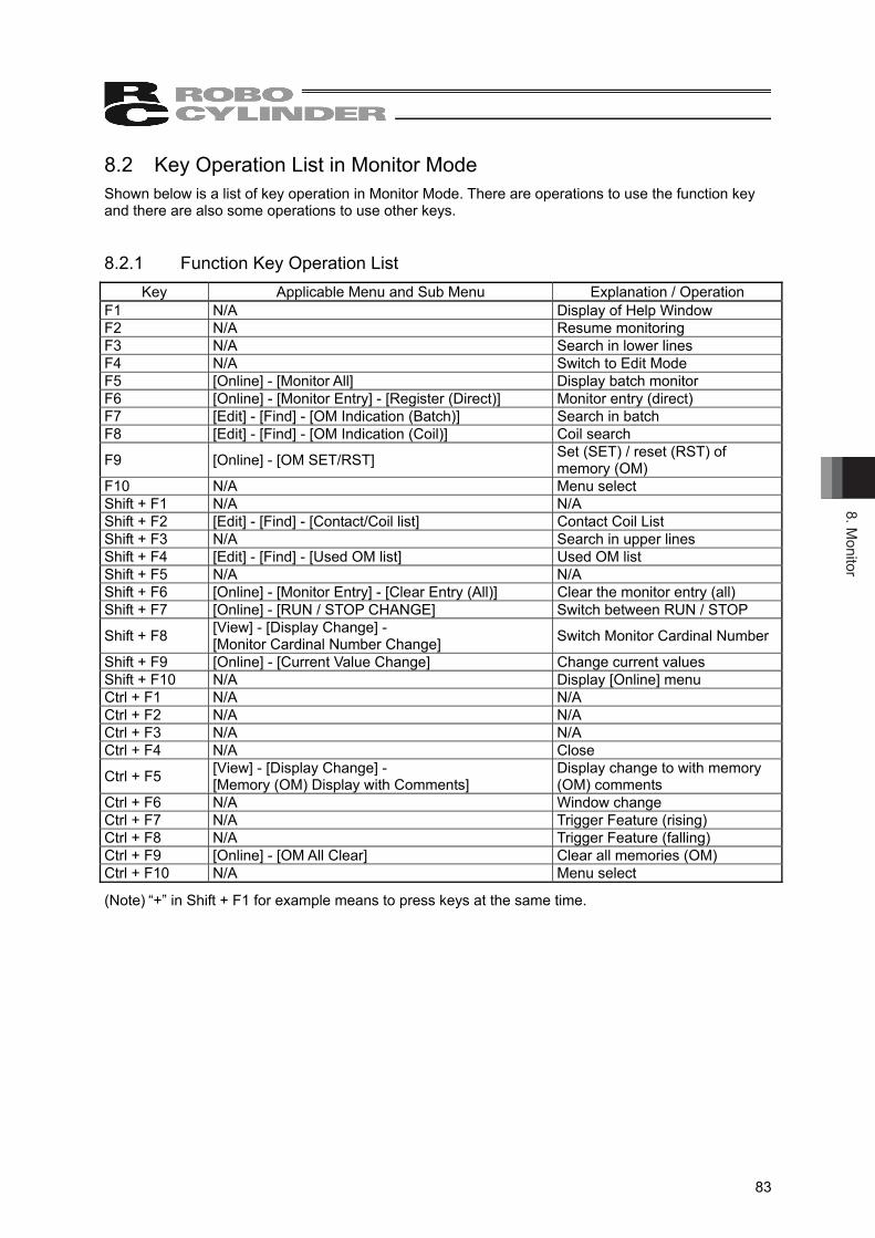
8. Monitor
83
8.2 Key Operation List in Monitor Mode Shown below is a list of key operation in Monitor Mode. There are operations to use the function key and there are also some operations to use other keys. 8.2.1 Function Key Operation List
Key Applicable Menu and Sub Menu Explanation / Operation F1 N/A Display of Help Window F2 N/A Resume monitoring F3 N/A Search in lower lines F4 N/A Switch to Edit Mode F5 [Online] - [Monitor All] Display batch monitor F6 [Online] - [Monitor Entry] - [Register (Direct)] Monitor entry (direct) F7 [Edit] - [Find] - [OM Indication (Batch)] Search in batch F8 [Edit] - [Find] - [OM Indication (Coil)] Coil search
F9 [Online] - [OM SET/RST] Set (SET) / reset (RST) of memory (OM)
F10 N/A Menu select Shift + F1 N/A N/A Shift + F2 [Edit] - [Find] - [Contact/Coil list] Contact Coil List Shift + F3 N/A Search in upper lines Shift + F4 [Edit] - [Find] - [Used OM list] Used OM list Shift + F5 N/A N/A Shift + F6 [Online] - [Monitor Entry] - [Clear Entry (All)] Clear the monitor entry (all) Shift + F7 [Online] - [RUN / STOP CHANGE] Switch between RUN / STOP
Shift + F8 [View] - [Display Change] - [Monitor Cardinal Number Change] Switch Monitor Cardinal Number
Shift + F9 [Online] - [Current Value Change] Change current values Shift + F10 N/A Display [Online] menu Ctrl + F1 N/A N/A Ctrl + F2 N/A N/A Ctrl + F3 N/A N/A Ctrl + F4 N/A Close
Ctrl + F5 [View] - [Display Change] - [Memory (OM) Display with Comments]
Display change to with memory (OM) comments
Ctrl + F6 N/A Window change Ctrl + F7 N/A Trigger Feature (rising) Ctrl + F8 N/A Trigger Feature (falling) Ctrl + F9 [Online] - [OM All Clear] Clear all memories (OM) Ctrl + F10 N/A Menu select
(Note) “+” in Shift + F1 for example means to press keys at the same time.
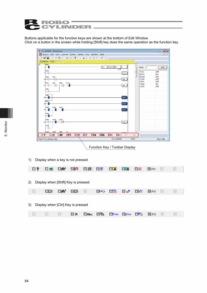
8. M
onito
r
84
Buttons applicable for the function keys are shown at the bottom of Edit Window. Click on a button in the screen while holding [Shift] key does the same operation as the function key.
Function Key / Toolbar Display
1) Display when a key is not pressed
2) Display when [Shift] Key is pressed
3) Display when [Ctrl] Key is pressed
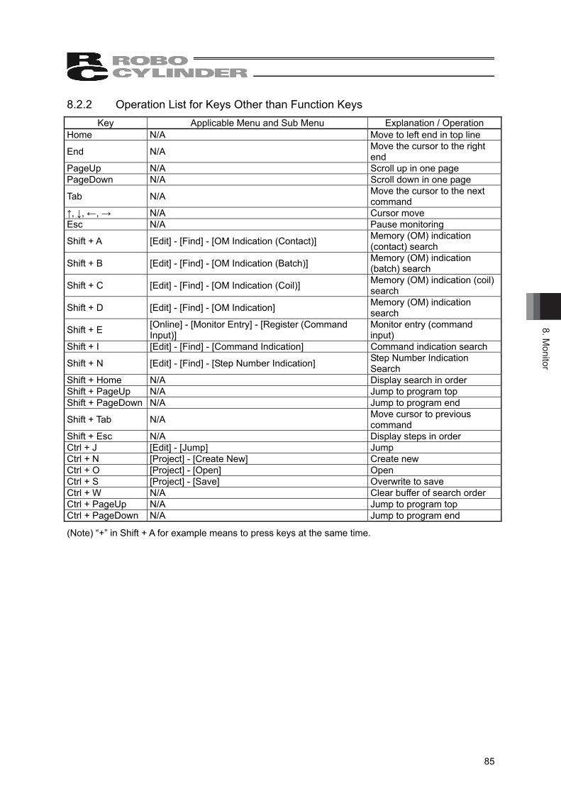
8. Monitor
85
8.2.2 Operation List for Keys Other than Function Keys Key Applicable Menu and Sub Menu Explanation / Operation
Home N/A Move to left end in top line
End N/A Move the cursor to the right end
PageUp N/A Scroll up in one page PageDown N/A Scroll down in one page
Tab N/A Move the cursor to the next command
↑, ↓, ←, → N/A Cursor move Esc N/A Pause monitoring
Shift + A [Edit] - [Find] - [OM Indication (Contact)] Memory (OM) indication (contact) search
Shift + B [Edit] - [Find] - [OM Indication (Batch)] Memory (OM) indication (batch) search
Shift + C [Edit] - [Find] - [OM Indication (Coil)] Memory (OM) indication (coil) search
Shift + D [Edit] - [Find] - [OM Indication] Memory (OM) indication search
Shift + E [Online] - [Monitor Entry] - [Register (Command Input)]
Monitor entry (command input)
Shift + I [Edit] - [Find] - [Command Indication] Command indication search
Shift + N [Edit] - [Find] - [Step Number Indication] Step Number Indication Search
Shift + Home N/A Display search in order Shift + PageUp N/A Jump to program top Shift + PageDown N/A Jump to program end
Shift + Tab N/A Move cursor to previous command
Shift + Esc N/A Display steps in order Ctrl + J [Edit] - [Jump] Jump Ctrl + N [Project] - [Create New] Create new Ctrl + O [Project] - [Open] Open Ctrl + S [Project] - [Save] Overwrite to save Ctrl + W N/A Clear buffer of search order Ctrl + PageUp N/A Jump to program top Ctrl + PageDown N/A Jump to program end
(Note) “+” in Shift + A for example means to press keys at the same time.
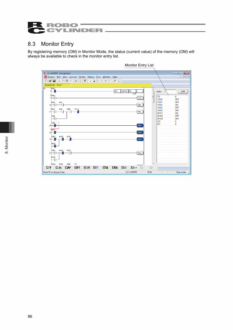
8. M
onito
r
86
8.3 Monitor Entry By registering memory (OM) in Monitor Mode, the status (current value) of the memory (OM) will always be available to check in the monitor entry list.
Monitor Entry List
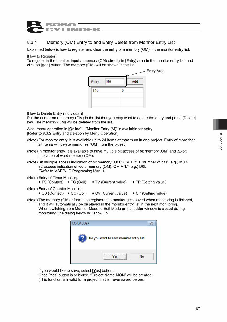
8. Monitor
87
8.3.1 Memory (OM) Entry to and Entry Delete from Monitor Entry List Explained below is how to register and clear the entry of a memory (OM) in the monitor entry list.
[How to Register] To register in the monitor, input a memory (OM) directly in [Entry] area in the monitor entry list, and click on [Add] button. The memory (OM) will be shown in the list. [How to Delete Entry (Individual)] Put the cursor on a memory (OM) in the list that you may want to delete the entry and press [Delete] key. The memory (OM) will be deleted from the list. Also, menu operation in [Online] – [Monitor Entry (M)] is available for entry. [Refer to 8.3.2 Entry and Deletion by Menu Operation]
(Note) For monitor entry, it is available up to 24 items at maximum in one project. Entry of more than 24 items will delete memories (OM) from the oldest.
(Note) In monitor entry, it is available to have multiple bit access of bit memory (OM) and 32-bit indication of word memory (OM).
(Note) Bit multiple access indication of bit memory (OM); OM + “:” + “number of bits”, e.g.) M0:4 32-access indication of word memory (OM); OM + “L”, e.g.) D0L [Refer to MSEP-LC Programing Manual]
(Note) Entry of Timer Monitor; TS (Contact) TC (Coil) TV (Current value) TP (Setting value)
(Note) Entry of Counter Monitor; CS (Contact) CC (Coil) CV (Current value) CP (Setting value)
(Note) The memory (OM) information registered in monitor gets saved when monitoring is finished, and it will automatically be displayed in the monitor entry list in the next monitoring. When switching from Monitor Mode to Edit Mode or the ladder window is closed during monitoring, the dialog below will show up.
If you would like to save, select [Yes] button. Once [Yes] button is selected, “Project Name.MON” will be created. (This function is invalid for a project that is never saved before.)
Entry Area
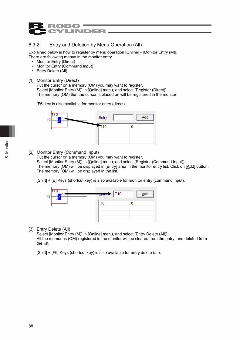
8. M
onito
r
88
8.3.2 Entry and Deletion by Menu Operation (All) Explained below is how to register by menu operation [Online] - [Monitor Entry (M)]. There are following menus in the monitor entry.
• Monitor Entry (Direct) • Monitor Entry (Command Input) • Entry Delete (All)
[1] Monitor Entry (Direct)
Put the cursor on a memory (OM) you may want to register. Select [Monitor Entry (M)] in [Online] menu, and select [Register (Direct)]. The memory (OM) that the cursor is placed on will be registered in the monitor. [F6] key is also available for monitor entry (direct).
[2] Monitor Entry (Command Input)
Put the cursor on a memory (OM) you may want to register. Select [Monitor Entry (M)] in [Online] menu, and select [Register (Command Input)]. The memory (OM) will be displayed in [Entry] area in the monitor entry list. Click on [Add] button. The memory (OM) will be displayed in the list. [Shift] + [E] Keys (shortcut key) is also available for monitor entry (command input).
[3] Entry Delete (All)
Select [Monitor Entry (M)] in [Online] menu, and select [Entry Delete (All)]. All the memories (OM) registered in the monitor will be cleared from the entry, and deleted from the list. [Shift] + [F6] Keys (shortcut key) is also available for entry delete (all).
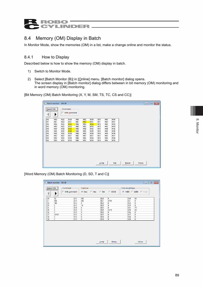
8. Monitor
89
8.4 Memory (OM) Display in Batch In Monitor Mode, show the memories (OM) in a list, make a change online and monitor the status. 8.4.1 How to Display Described below is how to show the memory (OM) display in batch.
1) Switch to Monitor Mode. 2) Select [Batch Monitor (B)] in [Online] menu. [Batch monitor] dialog opens.
The screen display in [Batch monitor] dialog differs between in bit memory (OM) monitoring and in word memory (OM) monitoring.
[Bit Memory (OM) Batch Monitoring (X, Y, M, SM, TS, TC, CS and CC)]
[Word Memory (OM) Batch Monitoring (D, SD, T and C)]
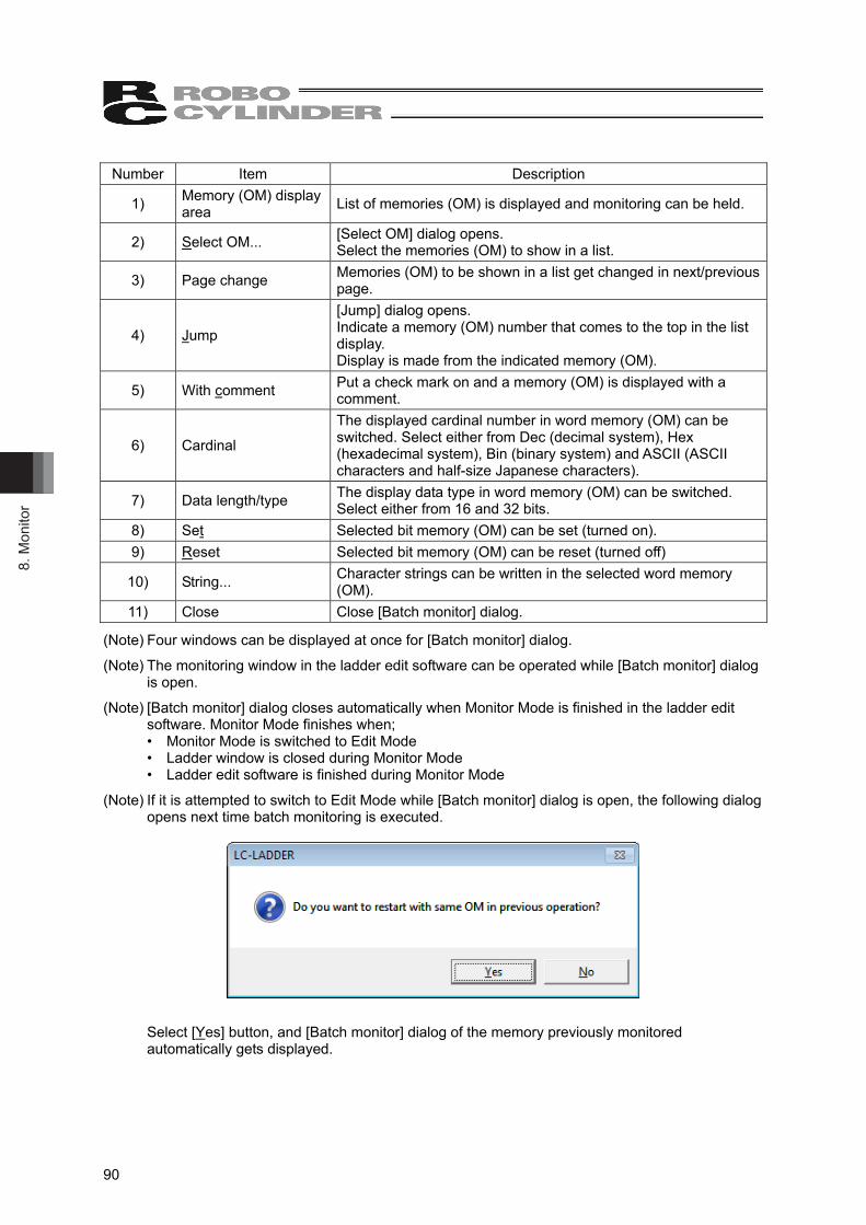
8. M
onito
r
90
Number Item Description
1) Memory (OM) display area List of memories (OM) is displayed and monitoring can be held.
2) Select OM... [Select OM] dialog opens. Select the memories (OM) to show in a list.
3) Page change Memories (OM) to be shown in a list get changed in next/previous page.
4) Jump
[Jump] dialog opens. Indicate a memory (OM) number that comes to the top in the list display. Display is made from the indicated memory (OM).
5) With comment Put a check mark on and a memory (OM) is displayed with a comment.
6) Cardinal
The displayed cardinal number in word memory (OM) can be switched. Select either from Dec (decimal system), Hex (hexadecimal system), Bin (binary system) and ASCII (ASCII characters and half-size Japanese characters).
7) Data length/type The display data type in word memory (OM) can be switched. Select either from 16 and 32 bits.
8) Set Selected bit memory (OM) can be set (turned on). 9) Reset Selected bit memory (OM) can be reset (turned off)
10) String... Character strings can be written in the selected word memory (OM).
11) Close Close [Batch monitor] dialog.
(Note) Four windows can be displayed at once for [Batch monitor] dialog.
(Note) The monitoring window in the ladder edit software can be operated while [Batch monitor] dialog is open.
(Note) [Batch monitor] dialog closes automatically when Monitor Mode is finished in the ladder edit software. Monitor Mode finishes when; • Monitor Mode is switched to Edit Mode • Ladder window is closed during Monitor Mode • Ladder edit software is finished during Monitor Mode
(Note) If it is attempted to switch to Edit Mode while [Batch monitor] dialog is open, the following dialog opens next time batch monitoring is executed.
Select [Yes] button, and [Batch monitor] dialog of the memory previously monitored automatically gets displayed.
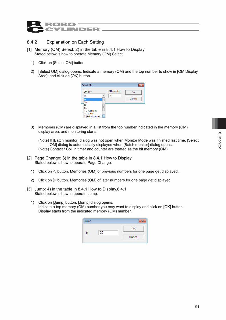
8. Monitor
91
8.4.2 Explanation on Each Setting [1] Memory (OM) Select: 2) in the table in 8.4.1 How to Display
Stated below is how to operate Memory (OM) Select. 1) Click on [Select OM] button. 2) [Select OM] dialog opens. Indicate a memory (OM) and the top number to show in [OM Display
Area], and click on [OK] button.
3) Memories (OM) are displayed in a list from the top number indicated in the memory (OM) display area, and monitoring starts. (Note) If [Batch monitor] dialog was not open when Monitor Mode was finished last time, [Select
OM] dialog is automatically displayed when [Batch monitor] dialog opens. (Note) Contact / Coil in timer and counter are treated as the bit memory (OM).
[2] Page Change: 3) in the table in 8.4.1 How to Display
Stated below is how to operate Page Change.
1) Click on button. Memories (OM) of previous numbers for one page get displayed. 2) Click on button. Memories (OM) of later numbers for one page get displayed.
[3] Jump: 4) in the table in 8.4.1 How to Display.8.4.1
Stated below is how to operate Jump. 1) Click on [Jump] button. [Jump] dialog opens.
Indicate a top memory (OM) number you may want to display and click on [OK] button. Display starts from the indicated memory (OM) number.
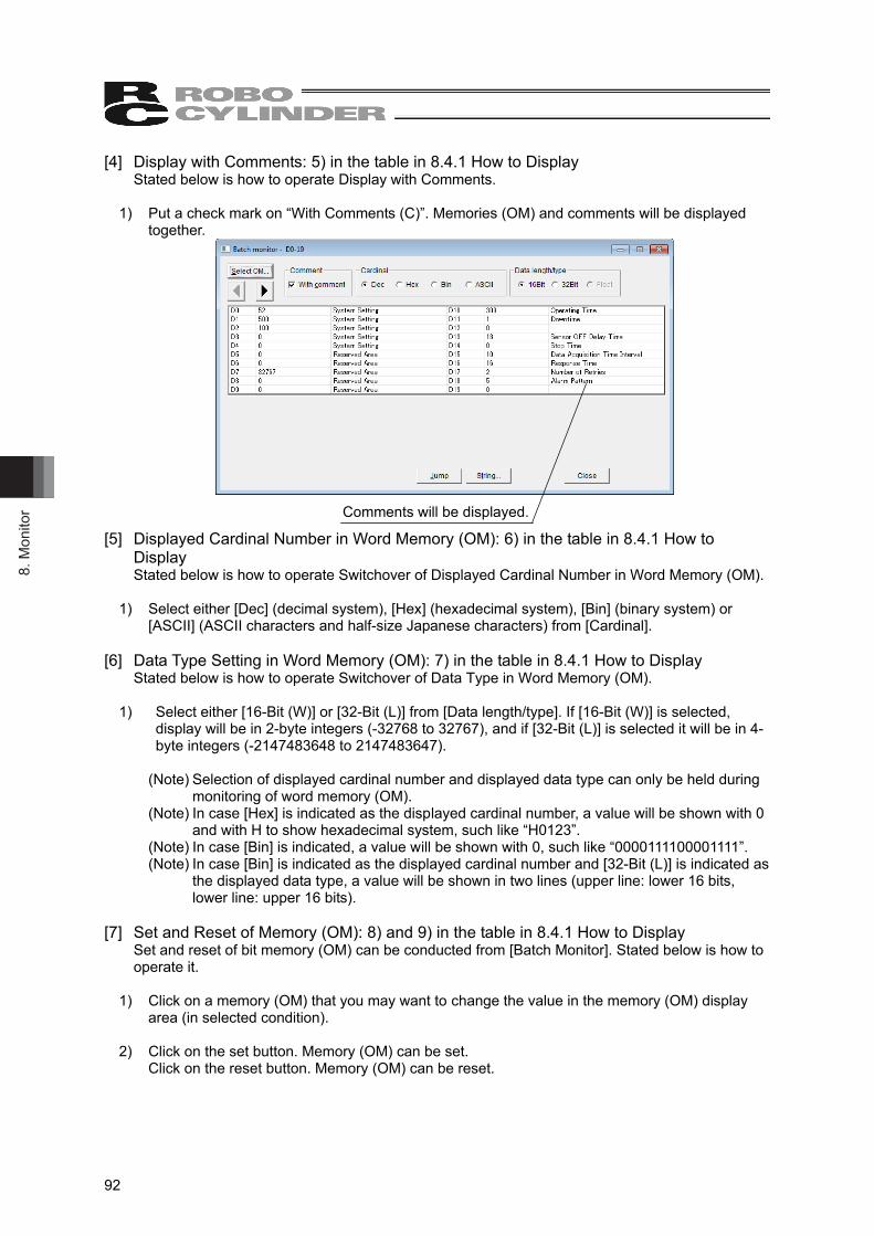
8. M
onito
r
92
[4] Display with Comments: 5) in the table in 8.4.1 How to Display Stated below is how to operate Display with Comments.
1) Put a check mark on “With Comments (C)”. Memories (OM) and comments will be displayed together.
[5] Displayed Cardinal Number in Word Memory (OM): 6) in the table in 8.4.1 How to Display Stated below is how to operate Switchover of Displayed Cardinal Number in Word Memory (OM).
1) Select either [Dec] (decimal system), [Hex] (hexadecimal system), [Bin] (binary system) or
[ASCII] (ASCII characters and half-size Japanese characters) from [Cardinal]. [6] Data Type Setting in Word Memory (OM): 7) in the table in 8.4.1 How to Display
Stated below is how to operate Switchover of Data Type in Word Memory (OM). 1) Select either [16-Bit (W)] or [32-Bit (L)] from [Data length/type]. If [16-Bit (W)] is selected,
display will be in 2-byte integers (-32768 to 32767), and if [32-Bit (L)] is selected it will be in 4-byte integers (-2147483648 to 2147483647).
(Note) Selection of displayed cardinal number and displayed data type can only be held during
monitoring of word memory (OM). (Note) In case [Hex] is indicated as the displayed cardinal number, a value will be shown with 0
and with H to show hexadecimal system, such like “H0123”. (Note) In case [Bin] is indicated, a value will be shown with 0, such like “0000111100001111”. (Note) In case [Bin] is indicated as the displayed cardinal number and [32-Bit (L)] is indicated as
the displayed data type, a value will be shown in two lines (upper line: lower 16 bits, lower line: upper 16 bits).
[7] Set and Reset of Memory (OM): 8) and 9) in the table in 8.4.1 How to Display
Set and reset of bit memory (OM) can be conducted from [Batch Monitor]. Stated below is how to operate it.
1) Click on a memory (OM) that you may want to change the value in the memory (OM) display
area (in selected condition). 2) Click on the set button. Memory (OM) can be set.
Click on the reset button. Memory (OM) can be reset.
Comments will be displayed.
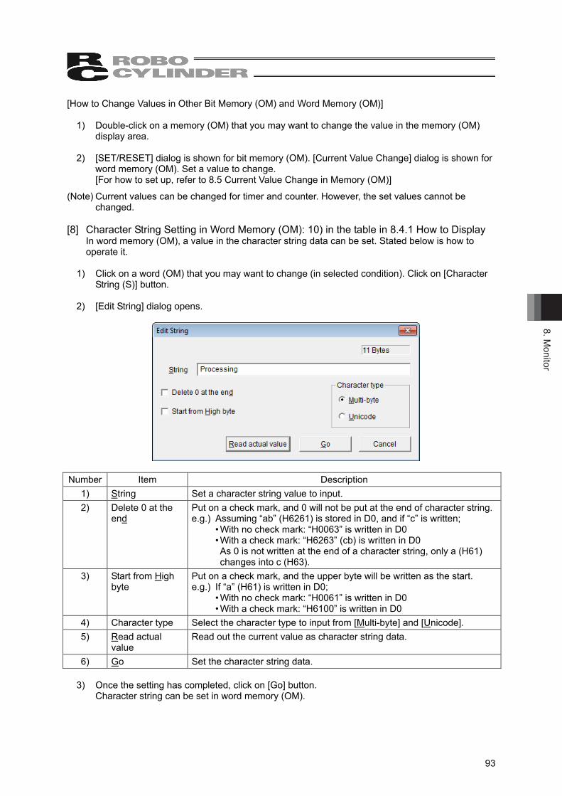
8. Monitor
93
[How to Change Values in Other Bit Memory (OM) and Word Memory (OM)] 1) Double-click on a memory (OM) that you may want to change the value in the memory (OM)
display area. 2) [SET/RESET] dialog is shown for bit memory (OM). [Current Value Change] dialog is shown for
word memory (OM). Set a value to change. [For how to set up, refer to 8.5 Current Value Change in Memory (OM)]
(Note) Current values can be changed for timer and counter. However, the set values cannot be changed.
[8] Character String Setting in Word Memory (OM): 10) in the table in 8.4.1 How to Display
In word memory (OM), a value in the character string data can be set. Stated below is how to operate it.
1) Click on a word (OM) that you may want to change (in selected condition). Click on [Character
String (S)] button. 2) [Edit String] dialog opens.
Number Item Description
1) String Set a character string value to input. 2) Delete 0 at the
end Put on a check mark, and 0 will not be put at the end of character string.e.g.) Assuming “ab” (H6261) is stored in D0, and if “c” is written;
• With no check mark: “H0063” is written in D0 • With a check mark: “H6263” (cb) is written in D0 As 0 is not written at the end of a character string, only a (H61) changes into c (H63).
3) Start from High byte
Put on a check mark, and the upper byte will be written as the start. e.g.) If “a” (H61) is written in D0;
• With no check mark: “H0061” is written in D0 • With a check mark: “H6100” is written in D0
4) Character type Select the character type to input from [Multi-byte] and [Unicode]. 5) Read actual
value Read out the current value as character string data.
6) Go Set the character string data. 3) Once the setting has completed, click on [Go] button.
Character string can be set in word memory (OM).
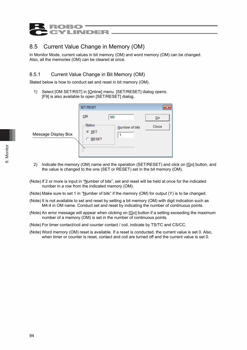
8. M
onito
r
94
8.5 Current Value Change in Memory (OM) In Monitor Mode, current values in bit memory (OM) and word memory (OM) can be changed. Also, all the memories (OM) can be cleared at once. 8.5.1 Current Value Change in Bit Memory (OM) Stated below is how to conduct set and reset in bit memory (OM).
1) Select [OM SET/RST] in [Online] menu. [SET/RESET] dialog opens. [F9] is also available to open [SET/RESET] dialog.
2) Indicate the memory (OM) name and the operation (SET/RESET) and click on [Go] button, and
the value is changed to the one (SET or RESET) set in the bit memory (OM).
(Note) If 2 or more is input in “Number of bits”, set and reset will be held at once for the indicated number in a row from the indicated memory (OM).
(Note) Make sure to set 1 in “Number of bits” if the memory (OM) for output (Y) is to be changed.
(Note) It is not available to set and reset by setting a bit memory (OM) with digit indication such as M4:4 in OM name. Conduct set and reset by indicating the number of continuous points.
(Note) An error message will appear when clicking on [Go] button if a setting exceeding the maximum number of a memory (OM) is set in the number of continuous points.
(Note) For timer contact/coil and counter contact / coil, indicate by TS/TC and CS/CC.
(Note) Word memory (OM) reset is available. If a reset is conducted, the current value is set 0. Also, when timer or counter is reset, contact and coil are turned off and the current value is set 0.
Message Display Box
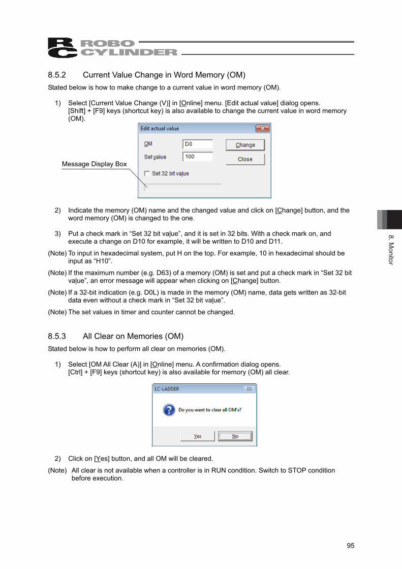
8. Monitor
95
8.5.2 Current Value Change in Word Memory (OM) Stated below is how to make change to a current value in word memory (OM).
1) Select [Current Value Change (V)] in [Online] menu. [Edit actual value] dialog opens. [Shift] + [F9] keys (shortcut key) is also available to change the current value in word memory (OM).
2) Indicate the memory (OM) name and the changed value and click on [Change] button, and the
word memory (OM) is changed to the one. 3) Put a check mark in “Set 32 bit value”, and it is set in 32 bits. With a check mark on, and
execute a change on D10 for example, it will be written to D10 and D11.
(Note) To input in hexadecimal system, put H on the top. For example, 10 in hexadecimal should be input as “H10”.
(Note) If the maximum number (e.g. D63) of a memory (OM) is set and put a check mark in “Set 32 bit value”, an error message will appear when clicking on [Change] button.
(Note) If a 32-bit indication (e.g. D0L) is made in the memory (OM) name, data gets written as 32-bit data even without a check mark in “Set 32 bit value”.
(Note) The set values in timer and counter cannot be changed. 8.5.3 All Clear on Memories (OM) Stated below is how to perform all clear on memories (OM).
1) Select [OM All Clear (A)] in [Online] menu. A confirmation dialog opens. [Ctrl] + [F9] keys (shortcut key) is also available for memory (OM) all clear.
2) Click on [Yes] button, and all OM will be cleared.
(Note) All clear is not available when a controller is in RUN condition. Switch to STOP condition before execution.
Message Display Box

8. M
onito
r
96
8.6 Stop Monitoring by Trigger Setting In Monitor Mode, monitoring can be stopped by either of OFF → ON (rising trigger) or ON → OFF (falling trigger) of bit memory (OM) in the monitoring of bit memory (OM). Stated below is how to do it.
1) Put the cursor on a bit memory (OM) to monitor. 2) To indicate “Rising Trigger”, press [Ctrl] + [F7] keys. To indicate “Falling Trigger”, press [Ctrl] +
[F8] keys.
(Note) The bit memory (OM) available to indicate in the trigger function is only one. If a setting is made after another one already set a trigger, the later one will become effective.
(Note) Word (OM) cannot be indicated in the trigger function.
(Note) To resume monitoring on the trigger stop, press [F2] key.
(Note) The trigger being set can be cleared when the monitoring is resumed or finished.
(Note) To stop monitoring, [Esc] key is also available.
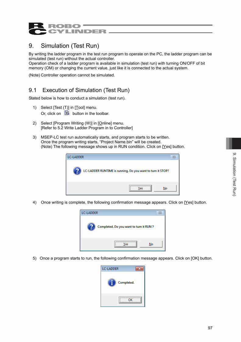
9. Simulation (Test R
un)
97
9. Simulation (Test Run) By writing the ladder program in the test run program to operate on the PC, the ladder program can be simulated (test run) without the actual controller. Operation check of a ladder program is available in simulation (test run) with turning ON/OFF of bit memory (OM) or changing the current value, just like it is connected to the actual system.
(Note) Controller operation cannot be simulated. 9.1 Execution of Simulation (Test Run) Stated below is how to conduct a simulation (test run).
1) Select [Test (T)] in [Tool] menu. Or, click on button in the toolbar.
2) Select [Program Writing (W)] in [Online] menu.
[Refer to 5.2 Write Ladder Program in to Controller] 3) MSEP-LC test run automatically starts, and program starts to be written.
Once the program writing starts, “Project Name.bin” will be created. (Note) The following message shows up in RUN condition. Click on [Yes] button.
4) Once writing is complete, the following confirmation message appears. Click on [Yes] button.
5) Once a program starts to run, the following confirmation message appears. Click on [OK] button.

9. S
imul
atio
n (T
est R
un)
98
6) Select [Start Monitoring (N)] in [Online] menu. 7) Conduct an operation check such as changing the current values of a memory (OM) with each
menu such as [Current Value Change (V)] in [Online]. Switch to debugging function if necessary. Conditional stop and step execution can be performed. [Refer to 7. Debugging Function DEBUG-RUN]
9.2 Simulation (Test Run) Finish It automatically finishes when the ladder edit software is finished.
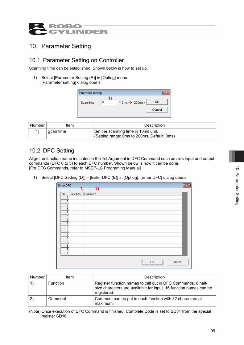
10. Parameter Setting
99
10. Parameter Setting 10.1 Parameter Setting on Controller Scanning time can be established. Shown below is how to set up.
1) Select [Parameter Setting (P)] in [Option] menu.
[Parameter setting] dialog opens.
Number Item Description
1) Scan time Set the scanning time in 10ms unit. (Setting range: 0ms to 200ms, Default: 0ms)
10.2 DFC Setting Align the function name indicated in the 1st Argument in DFC Command such as axis input and output commands (DFC 0 to 5) to each DFC number. Shown below is how it can be done. [For DFC Commands, refer to MSEP-LC Programing Manual]
1) Select [DFC Setting (D)] – [Enter DFC (E)] in [Option]. [Enter DFC] dialog opens.
Number Item Description 1) Function Register function names to call out in DFC Commands. 8 half-
size characters are available for input. 16 function names can be registered.
2) Comment Comment can be put in each function with 32 characters at maximum.
(Note) Once execution of DFC Command is finished, Complete Code is set to SD31 from the special register SD16.
1)
1)
2)
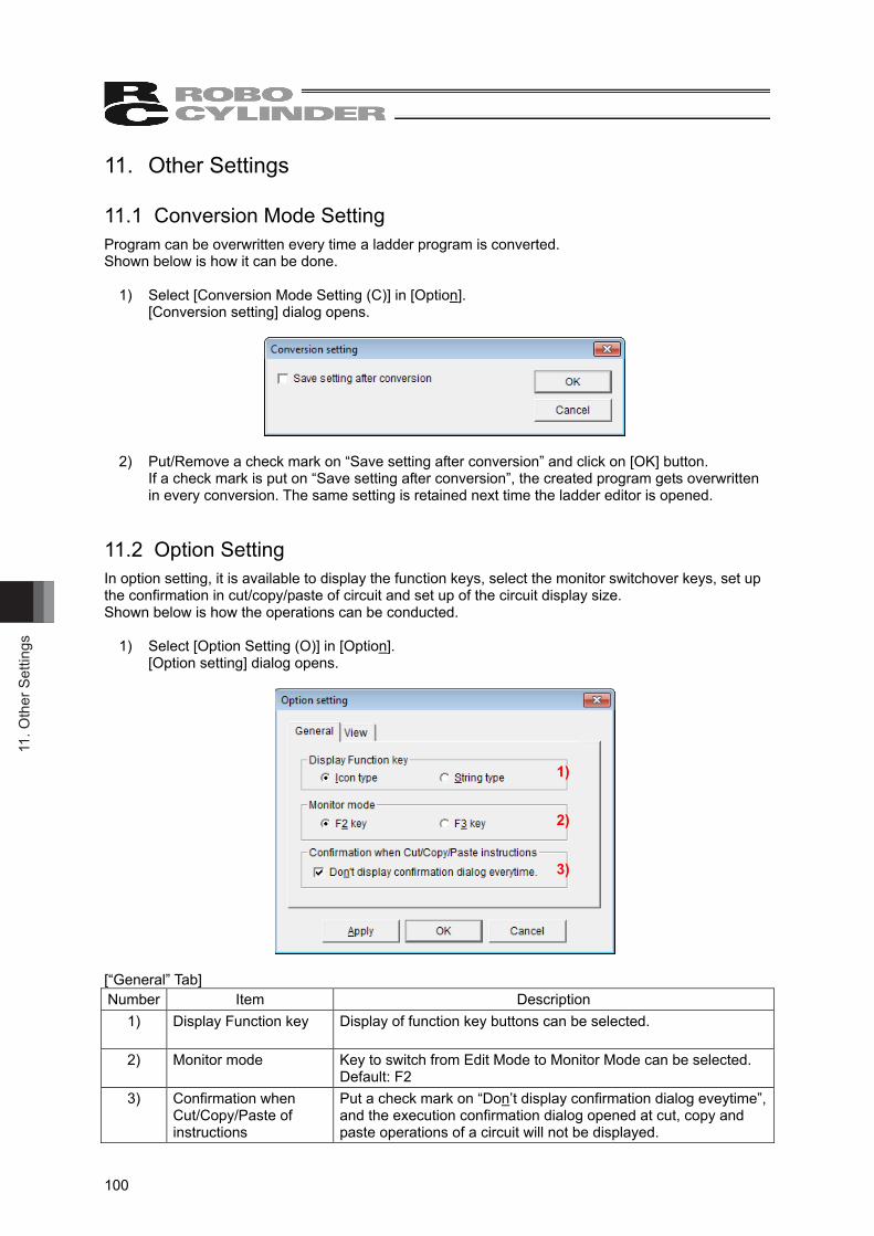
11. O
ther
Set
tings
100
11. Other Settings 11.1 Conversion Mode Setting Program can be overwritten every time a ladder program is converted. Shown below is how it can be done.
1) Select [Conversion Mode Setting (C)] in [Option].
[Conversion setting] dialog opens.
2) Put/Remove a check mark on “Save setting after conversion” and click on [OK] button.
If a check mark is put on “Save setting after conversion”, the created program gets overwritten in every conversion. The same setting is retained next time the ladder editor is opened.
11.2 Option Setting In option setting, it is available to display the function keys, select the monitor switchover keys, set up the confirmation in cut/copy/paste of circuit and set up of the circuit display size. Shown below is how the operations can be conducted.
1) Select [Option Setting (O)] in [Option].
[Option setting] dialog opens.
[“General” Tab] Number Item Description
1) Display Function key
Display of function key buttons can be selected.
2) Monitor mode Key to switch from Edit Mode to Monitor Mode can be selected. Default: F2
3) Confirmation when Cut/Copy/Paste of instructions
Put a check mark on “Don’t display confirmation dialog eveytime”, and the execution confirmation dialog opened at cut, copy and paste operations of a circuit will not be displayed.
1)
2)
3)
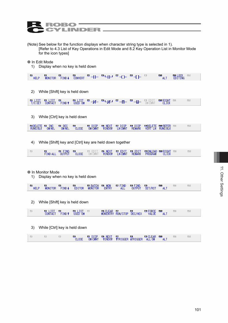
11. Other Settings
101
(Note) See below for the function displays when character string type is selected in 1). [Refer to 4.3 List of Key Operations in Edit Mode and 8.2 Key Operation List in Monitor Mode for the icon types]
In Edit Mode
1) Display when no key is held down
2) While [Shift] key is held down
3) While [Ctrl] key is held down
4) While [Shift] key and [Ctrl] key are held down together
In Monitor Mode 1) Display when no key is held down
2) While [Shift] key is held down
3) While [Ctrl] key is held down
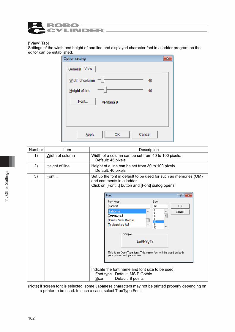
11. O
ther
Set
tings
102
[“View” Tab] Settings of the width and height of one line and displayed character font in a ladder program on the editor can be established.
Number Item Description
1) Width of column Width of a column can be set from 40 to 100 pixels. Default: 45 pixels
2) Height of line Height of a line can be set from 30 to 100 pixels. Default: 40 pixels
3) Font... Set up the font in default to be used for such as memories (OM) and comments in a ladder. Click on [Font...] button and [Font] dialog opens.
Indicate the font name and font size to be used.
Font type Default: MS P Gothic Size Default: 8 points
(Note) If screen font is selected, some Japanese characters may not be printed properly depending on a printer to be used. In such a case, select TrueType Font.
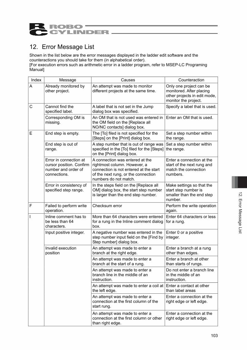
12. Error Message List
103
12. Error Message List Shown in the list below are the error messages displayed in the ladder edit software and the counteractions you should take for them (in alphabetical order). [For execution errors such as arithmetic error in a ladder program, refer to MSEP-LC Programing Manual] Index Message Causes Counteraction
A Already monitored by other project.
An attempt was made to monitor different projects at the same time.
Only one project can be monitored. After placing other projects in edit mode, monitor the project.
C Cannot find the specified label.
A label that is not set in the Jump dialog box was specified.
Specify a label that is used.
Corresponding OM is missing.
An OM that is not used was entered in the OM field on the [Replace all NO/NC contacts] dialog box.
Enter an OM that is used.
E End step is empty. The [To] filed is not specified for the [Steps] on the [Print] dialog box.
Set a step number within the range.
End step is out of range.
A step number that is out of range was specified in the [To] filed for the [Steps] on the [Print] dialog box.
Set a step number within the range.
Error in connection at cursor position. Confirm number and order of connections.
A connection was entered at the rightmost column. However, a connection is not entered at the start of the next rung, or the connection numbers do not match.
Enter a connection at the start of the next rung and match the connection numbers.
Error in consistency of specified step range.
In the steps field on the [Replace all OM] dialog box, the start step number is larger than the end step number.
Make settings so that the start step number is smaller than the end step number.
F Failed to perform write operation.
Checksum error Perform the write operation again.
I Inline comment has to be less than 64 characters.
More than 64 characters were entered for a rung in the Inline comment dialog box.
Enter 64 characters or less for a rung.
Input positive integer. A negative number was entered in the step number input field on the [Find by Step number] dialog box.
Enter 0 or a positive integer.
Invalid execution position
An attempt was made to enter a branch at the right edge.
Enter a branch at a rung other than edges.
An attempt was made to enter a branch at the start of a rung.
Enter a branch at other than starts of rungs.
An attempt was made to enter a branch line in the middle of an instruction.
Do not enter a branch line in the middle of an instruction.
An attempt was made to enter a coil at the left edge.
Enter a contact at other than label areas
An attempt was made to enter a connection at the first column of the start rung.
Enter a connection at the right edge or left edge.
An attempt was made to enter a connection at the first column or other than right edge.
Enter a connection at the right edge or left edge.
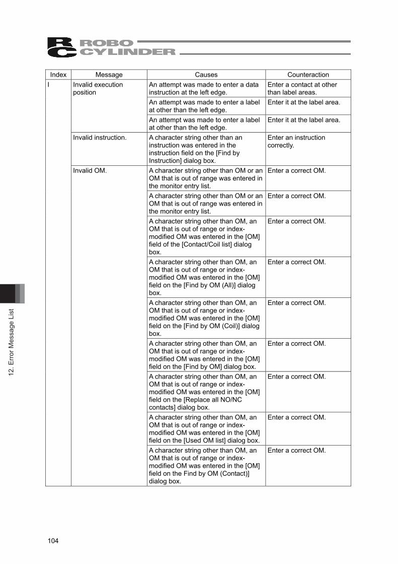
12. E
rror M
essa
ge L
ist
104
Index Message Causes Counteraction I Invalid execution
position An attempt was made to enter a data instruction at the left edge.
Enter a contact at other than label areas.
An attempt was made to enter a label at other than the left edge.
Enter it at the label area.
An attempt was made to enter a label at other than the left edge.
Enter it at the label area.
Invalid instruction. A character string other than an instruction was entered in the instruction field on the [Find by Instruction] dialog box.
Enter an instruction correctly.
Invalid OM. A character string other than OM or an OM that is out of range was entered in the monitor entry list.
Enter a correct OM.
A character string other than OM or an OM that is out of range was entered in the monitor entry list.
Enter a correct OM.
A character string other than OM, an OM that is out of range or index-modified OM was entered in the [OM] field of the [Contact/Coil list] dialog box.
Enter a correct OM.
A character string other than OM, an OM that is out of range or index-modified OM was entered in the [OM] field on the [Find by OM (All)] dialog box.
Enter a correct OM.
A character string other than OM, an OM that is out of range or index-modified OM was entered in the [OM] field on the [Find by OM (Coil)] dialog box.
Enter a correct OM.
A character string other than OM, an OM that is out of range or index-modified OM was entered in the [OM] field on the [Find by OM] dialog box.
Enter a correct OM.
A character string other than OM, an OM that is out of range or index-modified OM was entered in the [OM] field on the [Replace all NO/NC contacts] dialog box.
Enter a correct OM.
A character string other than OM, an OM that is out of range or index-modified OM was entered in the [OM] field on the [Used OM list] dialog box.
Enter a correct OM.
A character string other than OM, an OM that is out of range or index-modified OM was entered in the [OM] field on the Find by OM (Contact)] dialog box.
Enter a correct OM.
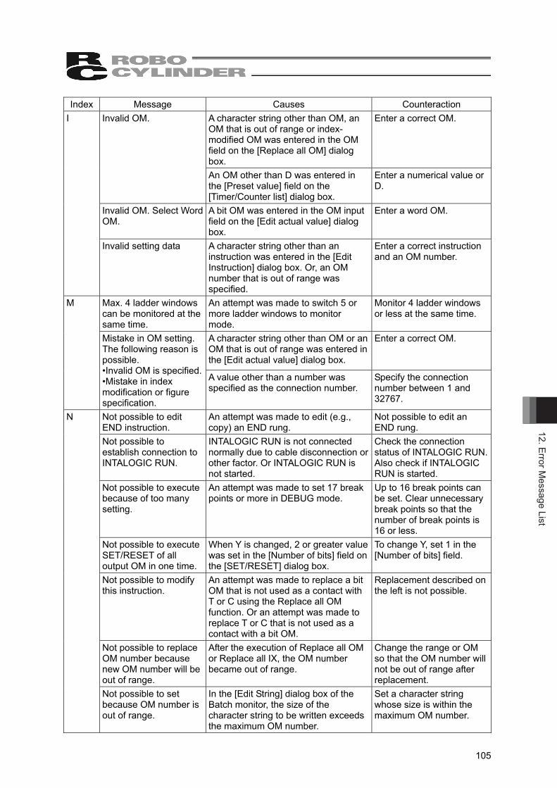
12. Error Message List
105
Index Message Causes Counteraction I Invalid OM. A character string other than OM, an
OM that is out of range or index-modified OM was entered in the OM field on the [Replace all OM] dialog box.
Enter a correct OM.
An OM other than D was entered in the [Preset value] field on the [Timer/Counter list] dialog box.
Enter a numerical value or D.
Invalid OM. Select Word OM.
A bit OM was entered in the OM input field on the [Edit actual value] dialog box.
Enter a word OM.
Invalid setting data A character string other than an instruction was entered in the [Edit Instruction] dialog box. Or, an OM number that is out of range was specified.
Enter a correct instruction and an OM number.
M Max. 4 ladder windows can be monitored at the same time.
An attempt was made to switch 5 or more ladder windows to monitor mode.
Monitor 4 ladder windows or less at the same time.
A character string other than OM or an OM that is out of range was entered in the [Edit actual value] dialog box.
Enter a correct OM.
Mistake in OM setting. The following reason is possible. •Invalid OM is specified. •Mistake in index modification or figure specification.
A value other than a number was specified as the connection number.
Specify the connection number between 1 and 32767.
N Not possible to edit END instruction.
An attempt was made to edit (e.g., copy) an END rung.
Not possible to edit an END rung.
Not possible to establish connection to INTALOGIC RUN.
INTALOGIC RUN is not connected normally due to cable disconnection or other factor. Or INTALOGIC RUN is not started.
Check the connection status of INTALOGIC RUN. Also check if INTALOGIC RUN is started.
Not possible to execute because of too many setting.
An attempt was made to set 17 break points or more in DEBUG mode.
Up to 16 break points can be set. Clear unnecessary break points so that the number of break points is 16 or less.
Not possible to execute SET/RESET of all output OM in one time.
When Y is changed, 2 or greater value was set in the [Number of bits] field on the [SET/RESET] dialog box.
To change Y, set 1 in the [Number of bits] field.
Not possible to modify this instruction.
An attempt was made to replace a bit OM that is not used as a contact with T or C using the Replace all OM function. Or an attempt was made to replace T or C that is not used as a contact with a bit OM.
Replacement described on the left is not possible.
Not possible to replace OM number because new OM number will be out of range.
After the execution of Replace all OM or Replace all IX, the OM number became out of range.
Change the range or OM so that the OM number will not be out of range after replacement.
Not possible to set because OM number is out of range.
In the [Edit String] dialog box of the Batch monitor, the size of the character string to be written exceeds the maximum OM number.
Set a character string whose size is within the maximum OM number.
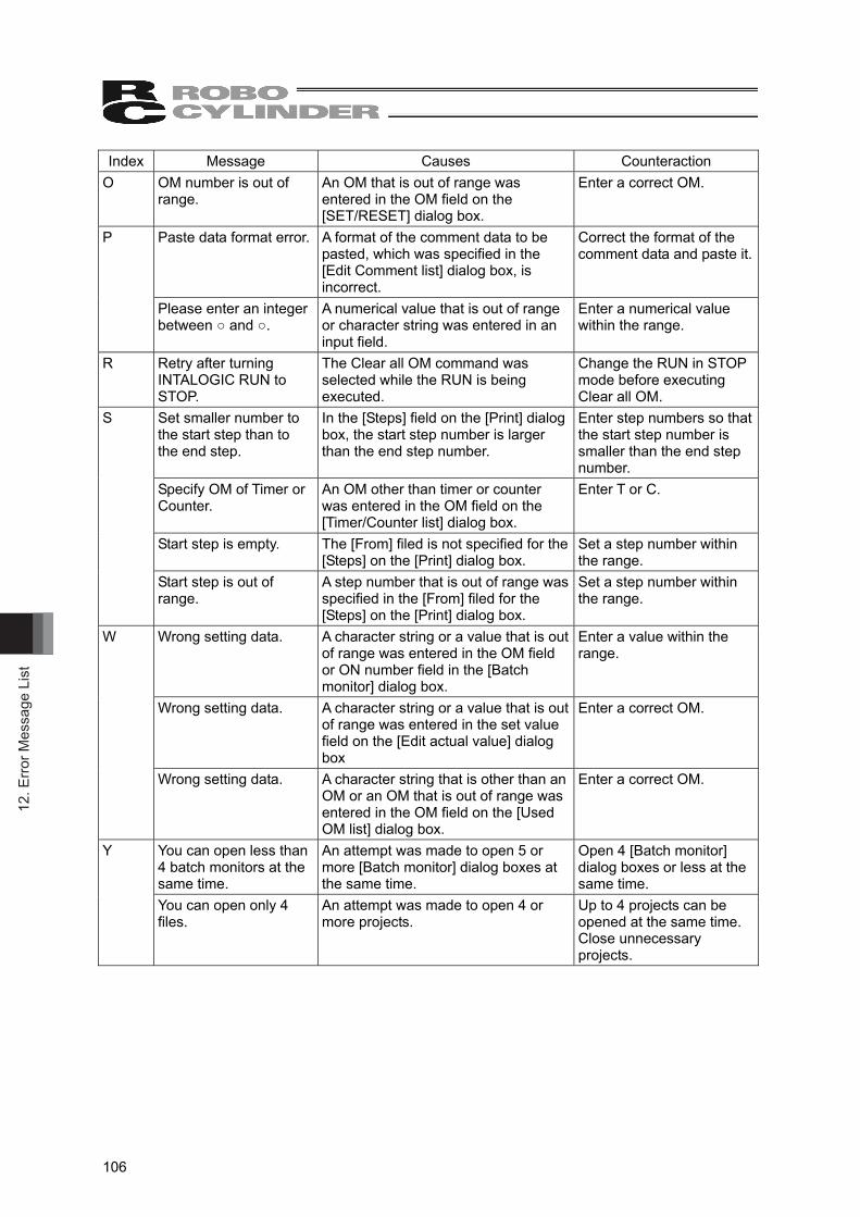
12. E
rror M
essa
ge L
ist
106
Index Message Causes Counteraction O OM number is out of
range. An OM that is out of range was entered in the OM field on the [SET/RESET] dialog box.
Enter a correct OM.
P Paste data format error. A format of the comment data to be pasted, which was specified in the [Edit Comment list] dialog box, is incorrect.
Correct the format of the comment data and paste it.
Please enter an integer between ○ and ○.
A numerical value that is out of range or character string was entered in an input field.
Enter a numerical value within the range.
R Retry after turning INTALOGIC RUN to STOP.
The Clear all OM command was selected while the RUN is being executed.
Change the RUN in STOP mode before executing Clear all OM.
S Set smaller number to the start step than to the end step.
In the [Steps] field on the [Print] dialog box, the start step number is larger than the end step number.
Enter step numbers so that the start step number is smaller than the end step number.
Specify OM of Timer or Counter.
An OM other than timer or counter was entered in the OM field on the [Timer/Counter list] dialog box.
Enter T or C.
Start step is empty. The [From] filed is not specified for the [Steps] on the [Print] dialog box.
Set a step number within the range.
Start step is out of range.
A step number that is out of range was specified in the [From] filed for the [Steps] on the [Print] dialog box.
Set a step number within the range.
W Wrong setting data. A character string or a value that is out of range was entered in the OM field or ON number field in the [Batch monitor] dialog box.
Enter a value within the range.
Wrong setting data. A character string or a value that is out of range was entered in the set value field on the [Edit actual value] dialog box
Enter a correct OM.
Wrong setting data. A character string that is other than an OM or an OM that is out of range was entered in the OM field on the [Used OM list] dialog box.
Enter a correct OM.
Y You can open less than 4 batch monitors at the same time.
An attempt was made to open 5 or more [Batch monitor] dialog boxes at the same time.
Open 4 [Batch monitor] dialog boxes or less at the same time.
You can open only 4 files.
An attempt was made to open 4 or more projects.
Up to 4 projects can be opened at the same time. Close unnecessary projects.
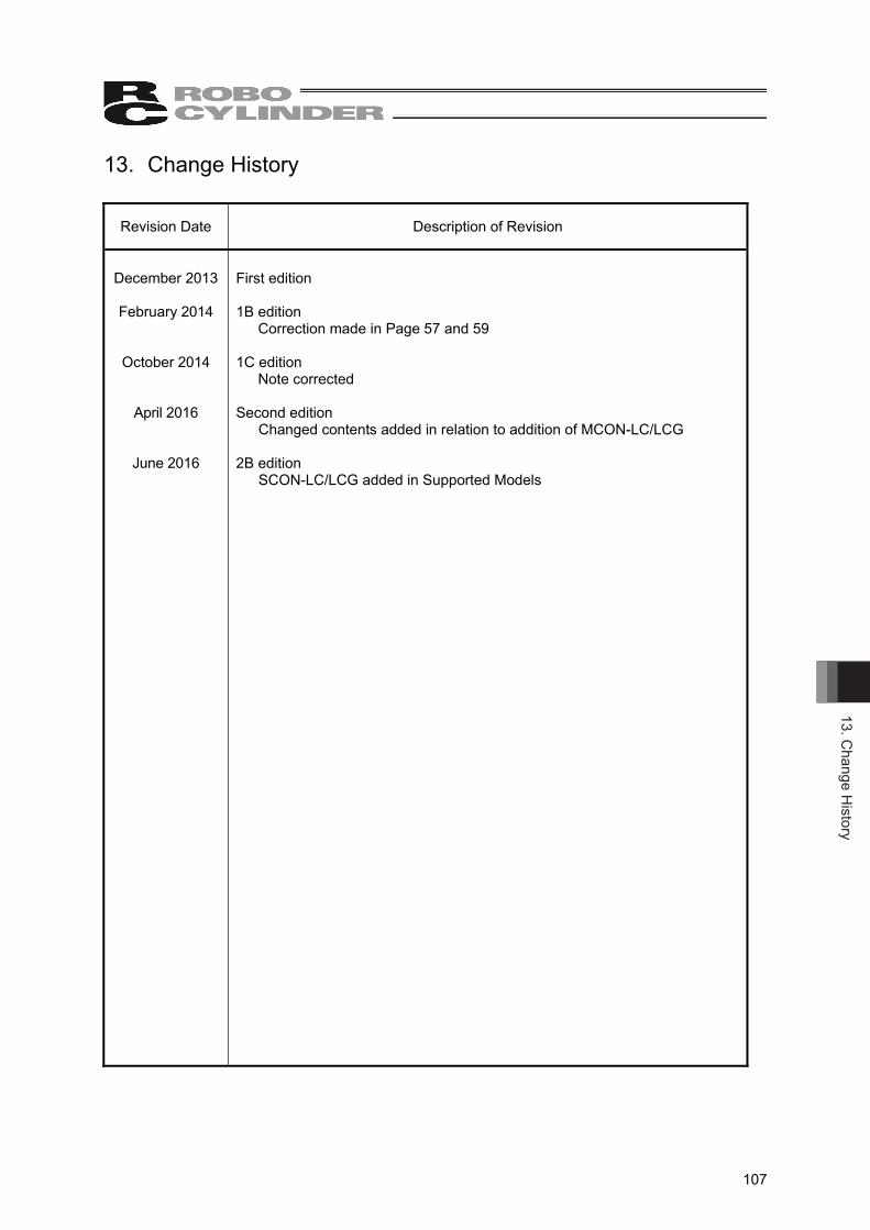
13. Change H
istory
107
13. Change History
Revision Date Description of Revision
December 2013
February 2014
October 2014
April 2016
June 2016
First edition 1B edition
Correction made in Page 57 and 59 1C edition
Note corrected
Second edition Changed contents added in relation to addition of MCON-LC/LCG
2B edition SCON-LC/LCG added in Supported Models


Manual No.: ME0330-2B (June 2016)
The information contained in this document is subject to change without notice for purposes of product improvement.Copyright © 2016. Jun. IAI Corporation. All rights reserved.
16.06.000
Head Office: 577-1 Obane Shimizu-KU Shizuoka City Shizuoka 424-0103, JapanTEL +81-54-364-5105 FAX +81-54-364-2589
website: www.iai-robot.co.jp/
Ober der Röth 4, D-65824 Schwalbach am Taunus, GermanyTEL 06196-88950 FAX 06196-889524
SHANGHAI JIAHUA BUSINESS CENTER A8-303, 808, Hongqiao Rd. Shanghai 200030, ChinaTEL 021-6448-4753 FAX 021-6448-3992
website: www.iai-robot.com
Technical Support available in USA, Europe and China
Head Office: 2690 W. 237th Street, Torrance, CA 90505TEL (310) 891-6015 FAX (310) 891-0815
Chicago Office: 110 East State Parkway, Schaumburg, IL 60173TEL (847) 908-1400 FAX (847) 908-1399
TEL (678) 354-9470 FAX (678) 354-9471website: www.intelligentactuator.com
Atlanta Office: 1220 Kennestone Circle, Suite 108, Marietta, GA 30066
825, PhairojKijja Tower 12th Floor, Bangna-Trad RD., Bangna, Bangna, Bangkok 10260, ThailandTEL +66-2-361-4458 FAX +66-2-361-4456


