
McGraw-Hill©The McGraw-Hill Companies, Inc., 2004 1 Transport Layer PART V.
57
1 McGraw-Hill ©The McGraw-Hill Companies, Inc., 2004 Transport Layer Transport Layer PART V PART V
-
Upload
aniya-ashwood -
Category
Documents
-
view
215 -
download
2
Transcript of McGraw-Hill©The McGraw-Hill Companies, Inc., 2004 1 Transport Layer PART V.

1McGraw-Hill ©The McGraw-Hill Companies, Inc., 2004
Transport LayerTransport Layer
PART VPART V
2McGraw-Hill ©The McGraw-Hill Companies, Inc., 2004
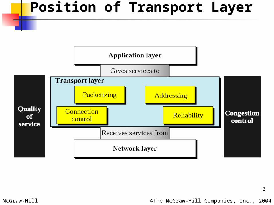
Position of Transport Layer

3McGraw-Hill ©The McGraw-Hill Companies, Inc., 2004
Transport Layer Duties

4McGraw-Hill ©The McGraw-Hill Companies, Inc., 2004
OBJECTIVES Packetizing
Division of large message Adding transport-layer header
Connection control Connection-oriented delivery: Virtual path
between sender and receiver Connectionless delivery
Addressing Logical address (Network Layer) Server application process: port number Client application process: port number
Reliability: involves flow control and error control Flow control, error control, congestion
control, QoS

5McGraw-Hill ©The McGraw-Hill Companies, Inc., 2004
Chapters
Chapter 22 Process-to-Process Delivery
Chapter 23 Congestion Control and QoS
6McGraw-Hill ©The McGraw-Hill Companies, Inc., 2004
Chapter 22
Process-to-ProcessDelivery:
UDP and TCP
7McGraw-Hill ©The McGraw-Hill Companies, Inc., 2004
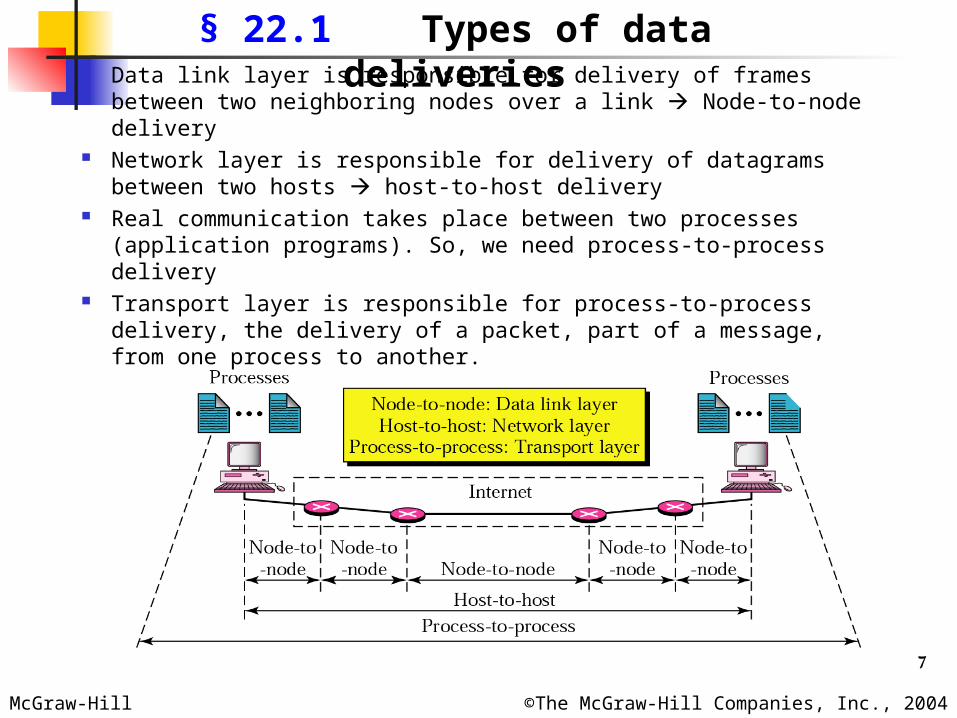
§ 22.1 Types of data deliveries Data link layer is responsible for delivery of frames between
two neighboring nodes over a link Node-to-node delivery Network layer is responsible for delivery of datagrams
between two hosts host-to-host delivery Real communication takes place between two processes
(application programs). So, we need process-to-process delivery
Transport layer is responsible for process-to-process delivery, the delivery of a packet, part of a message, from one process to another.

8McGraw-Hill ©The McGraw-Hill Companies, Inc., 2004
Client-Server Paradigm
Common process-to-process communication is via client-server paradigm
A process on the local host, called a client, needs services from a process usually on a remote host, called a server
Both the client and server processes have the same name. Ex. Daytime client and Daytime server.
A remote computer can run several server programs at the same time, just as local computers can run one or more client programs at the same time.
For communication, we need: Local host, local process, remote host and remote process
9McGraw-Hill ©The McGraw-Hill Companies, Inc., 2004
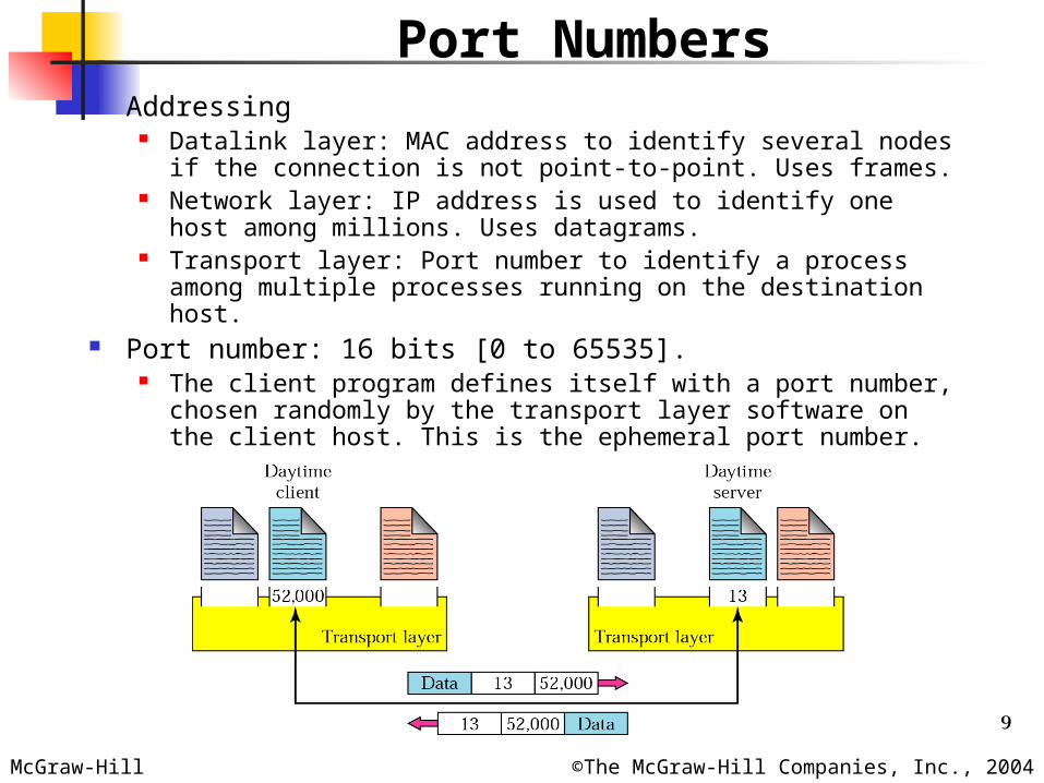
Port Numbers Addressing
Datalink layer: MAC address to identify several nodes if the connection is not point-to-point. Uses frames.
Network layer: IP address is used to identify one host among millions. Uses datagrams.
Transport layer: Port number to identify a process among multiple processes running on the destination host.
Port number: 16 bits [0 to 65535]. The client program defines itself with a port number,
chosen randomly by the transport layer software on the client host. This is the ephemeral port number.
10McGraw-Hill ©The McGraw-Hill Companies, Inc., 2004
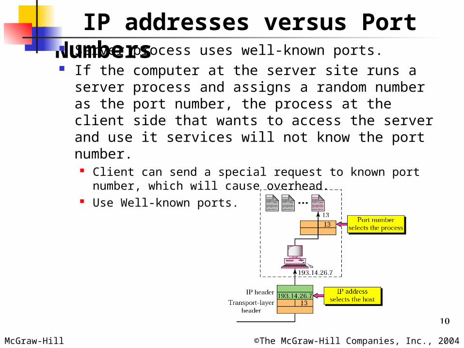
IP addresses versus Port Numbers Server process uses well-known ports. If the computer at the server site runs a server
process and assigns a random number as the port number, the process at the client side that wants to access the server and use it services will not know the port number.
Client can send a special request to known port number, which will cause overhead.
Use Well-known ports.
11McGraw-Hill ©The McGraw-Hill Companies, Inc., 2004
IANA ranges
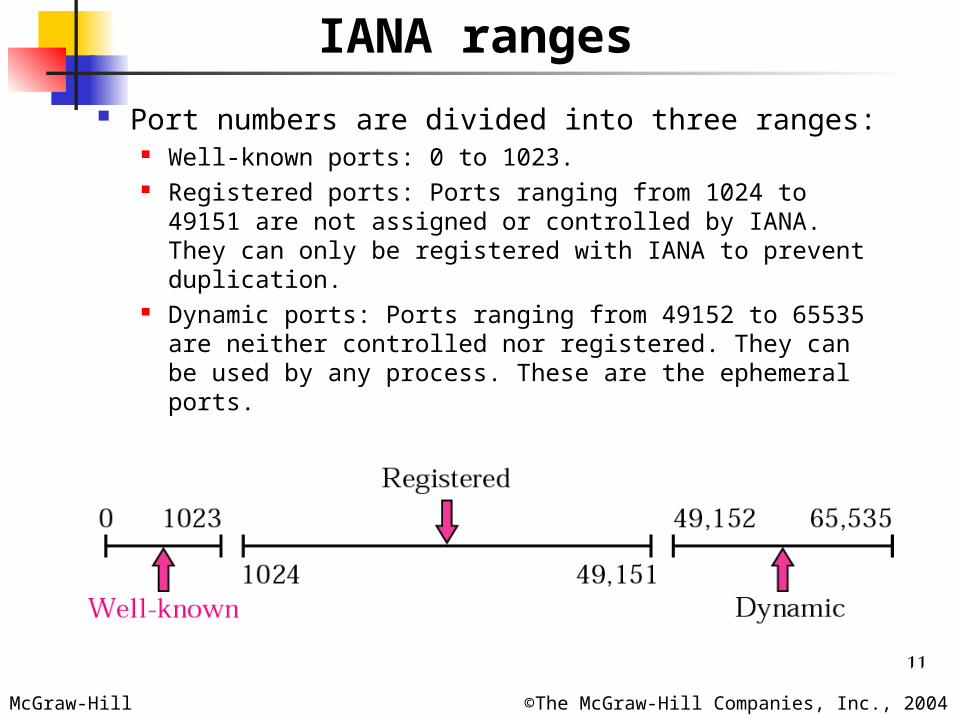
Port numbers are divided into three ranges: Well-known ports: 0 to 1023. Registered ports: Ports ranging from 1024 to 49151
are not assigned or controlled by IANA. They can only be registered with IANA to prevent duplication.
Dynamic ports: Ports ranging from 49152 to 65535 are neither controlled nor registered. They can be used by any process. These are the ephemeral ports.
12McGraw-Hill ©The McGraw-Hill Companies, Inc., 2004
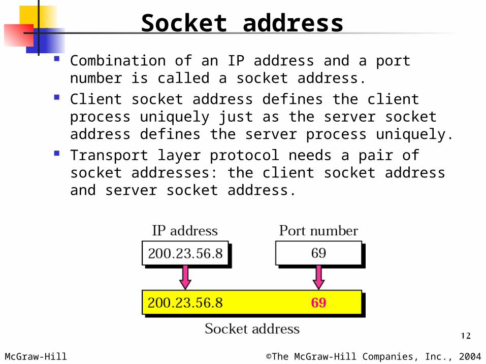
Socket address Combination of an IP address and a port
number is called a socket address. Client socket address defines the client
process uniquely just as the server socket address defines the server process uniquely.
Transport layer protocol needs a pair of socket addresses: the client socket address and server socket address.
13McGraw-Hill ©The McGraw-Hill Companies, Inc., 2004
Multiplexing and Demultiplexing
Multiplexing At the sender site, there may be several
processes that need to send packets. However, there is only one transport-layer protocol [UDP or TCP].
Protocol accepts messages from different process, differentiated by their assigned port number. After adding the header, the transport layer passes the packet to network layer.
Demultiplexing At receiver site, the transport layer receives
datagrams/segments from network layer. After error checking and dropping of the header,
the transport layer delivers each message to the appropriate process based on the port number.

14McGraw-Hill ©The McGraw-Hill Companies, Inc., 2004
Multiplexing and Demultiplexing
15McGraw-Hill ©The McGraw-Hill Companies, Inc., 2004
Connection oriented and Connectionless
Connectionless service Packets are sent from one party to another with no
need for connection establishment or connection release.
Packets are not numbered; they may be delayed, lost, or arrive out of sequence.
No acknowledgement. UDP [User Datagram Protocol]
Connection-oriented service Connection is first established between the sender
and the receiver Data are transferred At the end, the connection is released. TCP [Transmission Control Protocol]
16McGraw-Hill ©The McGraw-Hill Companies, Inc., 2004
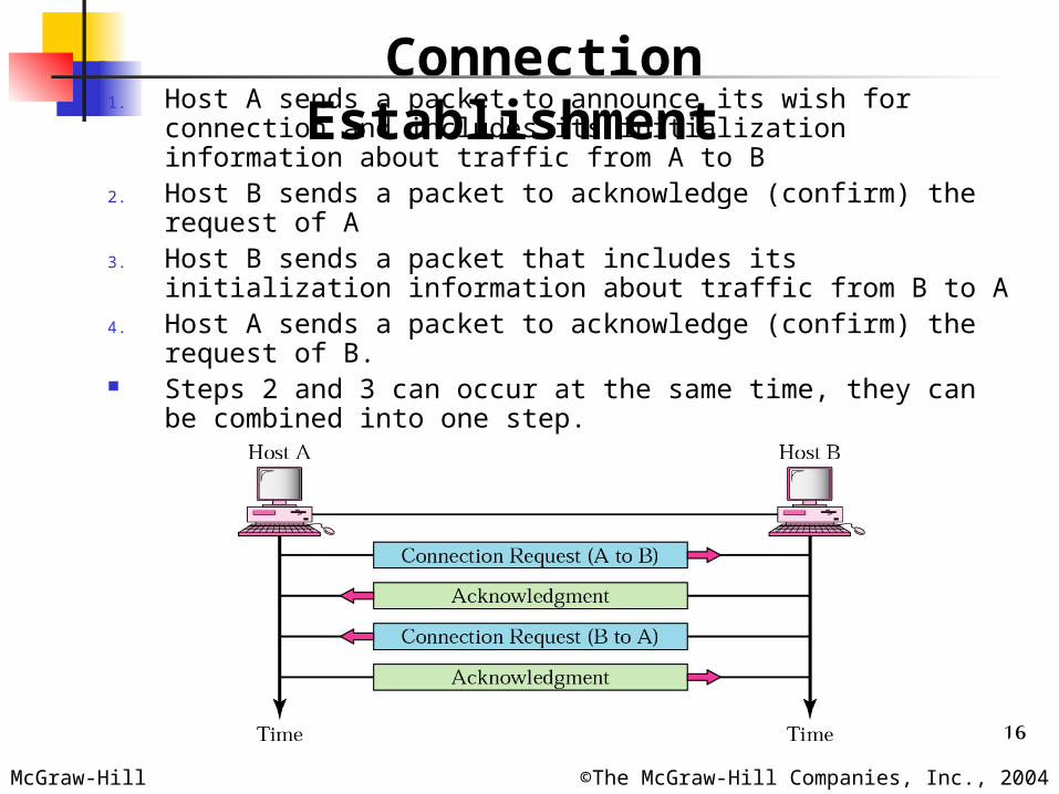
Connection Establishment1. Host A sends a packet to announce its wish for connection
and includes its initialization information about traffic from A to B
2. Host B sends a packet to acknowledge (confirm) the request of A
3. Host B sends a packet that includes its initialization information about traffic from B to A
4. Host A sends a packet to acknowledge (confirm) the request of B.
Steps 2 and 3 can occur at the same time, they can be combined into one step.

17McGraw-Hill ©The McGraw-Hill Companies, Inc., 2004
Each connection request needs to have a sequence number to recover from the loss or duplication of the packet. Also each acknowledgement needs to have an acknowledgement number for the same reason.
First sequence number in each direction must be random for each connection established.
A sender cannot create several connections that start with the same sequence number.
The reason is to prevent a situation called Playback. Using a sequence number for each connection
requires that the receiver keep a history of sequence numbers for each remote host for a specified time.
Connection Establishment
18McGraw-Hill ©The McGraw-Hill Companies, Inc., 2004
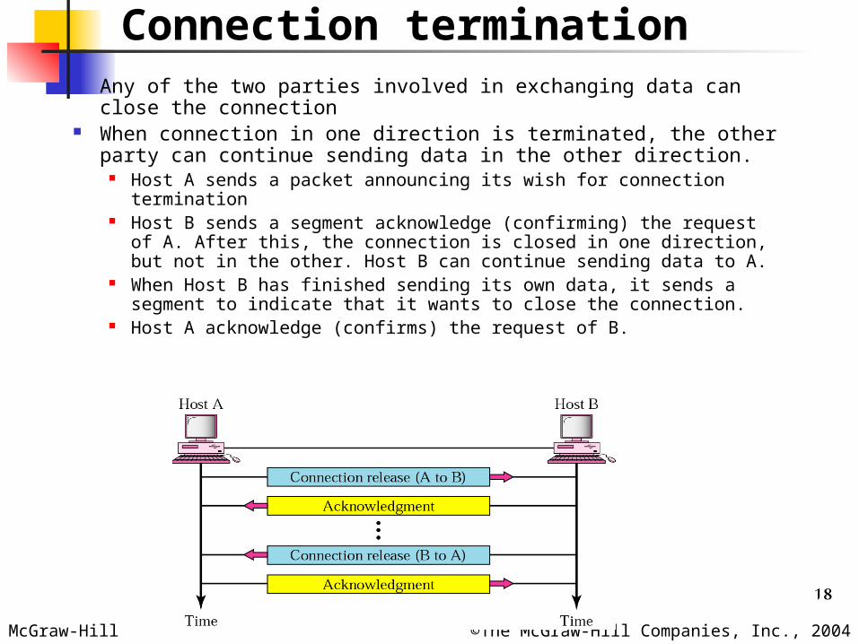
Connection termination Any of the two parties involved in exchanging data can
close the connection When connection in one direction is terminated, the other
party can continue sending data in the other direction. Host A sends a packet announcing its wish for connection
termination Host B sends a segment acknowledge (confirming) the request
of A. After this, the connection is closed in one direction, but not in the other. Host B can continue sending data to A.
When Host B has finished sending its own data, it sends a segment to indicate that it wants to close the connection.
Host A acknowledge (confirms) the request of B.
19McGraw-Hill ©The McGraw-Hill Companies, Inc., 2004
Connection-oriented[TCP] over Connectionless[IP]
According to the design goal of the Internet model, the two layers (Transport and Network) are totally independent.
Transport layer only uses the services of the network layer.
Reliable versus unreliable If the application-layer program needs reliability, we use
a reliability transport-layer protocol by implementing flow and error control at the transport layer.
If the application-layer program does not need reliability because it uses its own flow and error control mechanism or it needs fast service or the nature of the service does not demand flow and error control (real-time application), then an unreliable protocol can be used.
20McGraw-Hill ©The McGraw-Hill Companies, Inc., 2004
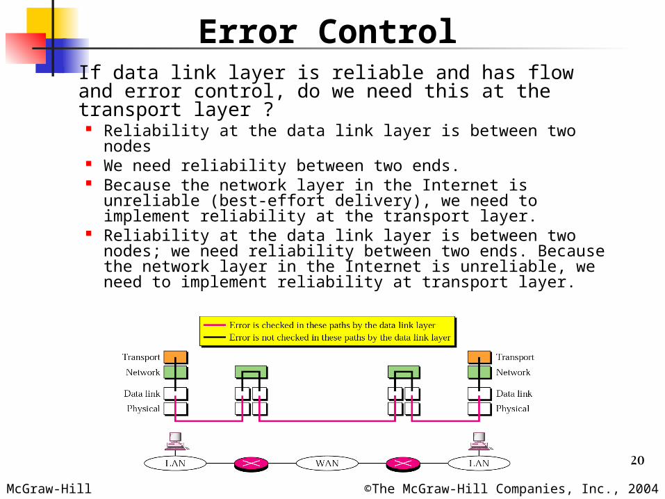
Error Control If data link layer is reliable and has flow and error
control, do we need this at the transport layer ? Reliability at the data link layer is between two nodes We need reliability between two ends. Because the network layer in the Internet is unreliable
(best-effort delivery), we need to implement reliability at the transport layer.
Reliability at the data link layer is between two nodes; we need reliability between two ends. Because the network layer in the Internet is unreliable, we need to implement reliability at transport layer.
21McGraw-Hill ©The McGraw-Hill Companies, Inc., 2004
§22.2 UDP
UDP is a connectionless, unreliable transport protocol. It does not add anything to the services of IP except for
providing process-to-process communication instead of host-to-host communication.
It performs very limited error checking. UDP is a very small protocol with a minimum of overhead. If a process wants to send a small message and does not
care much about reliability, it can use UDP Sending a small message using UDP takes much less
interaction between the sender and receiver than using TCP.
UDP is a convenient protocol for multimedia and multicasting applications.
UDP is a connectionless, unreliable protocol that has no flow and error control. It uses port numbers to multiplex data from the application layer.
22McGraw-Hill ©The McGraw-Hill Companies, Inc., 2004
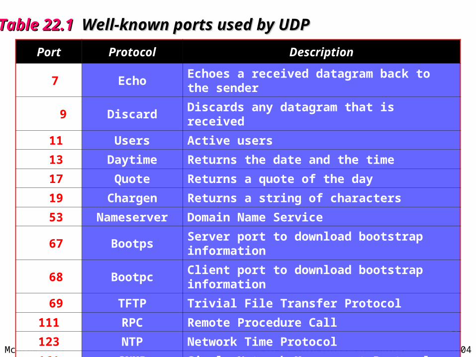
Table 22.1 Table 22.1 Well-known ports used by UDPWell-known ports used by UDP
Port Protocol Description
7 Echo Echoes a received datagram back to the sender
9 Discard Discards any datagram that is received
11 Users Active users
13 Daytime Returns the date and the time
17 Quote Returns a quote of the day
19 Chargen Returns a string of characters
53 Nameserver Domain Name Service
67 Bootps Server port to download bootstrap information
68 Bootpc Client port to download bootstrap information
69 TFTP Trivial File Transfer Protocol
111 RPC Remote Procedure Call
123 NTP Network Time Protocol
161 SNMP Simple Network Management Protocol
162 SNMP Simple Network Management Protocol (trap)
23McGraw-Hill ©The McGraw-Hill Companies, Inc., 2004
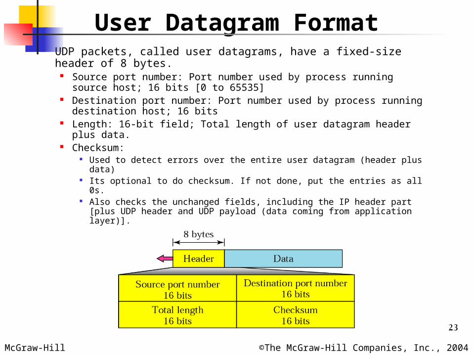
User Datagram Format UDP packets, called user datagrams, have a fixed-size
header of 8 bytes. Source port number: Port number used by process running
source host; 16 bits [0 to 65535] Destination port number: Port number used by process running
destination host; 16 bits Length: 16-bit field; Total length of user datagram header plus
data. Checksum:
Used to detect errors over the entire user datagram (header plus data)
Its optional to do checksum. If not done, put the entries as all 0s. Also checks the unchanged fields, including the IP header part [plus
UDP header and UDP payload (data coming from application layer)].
24McGraw-Hill ©The McGraw-Hill Companies, Inc., 2004
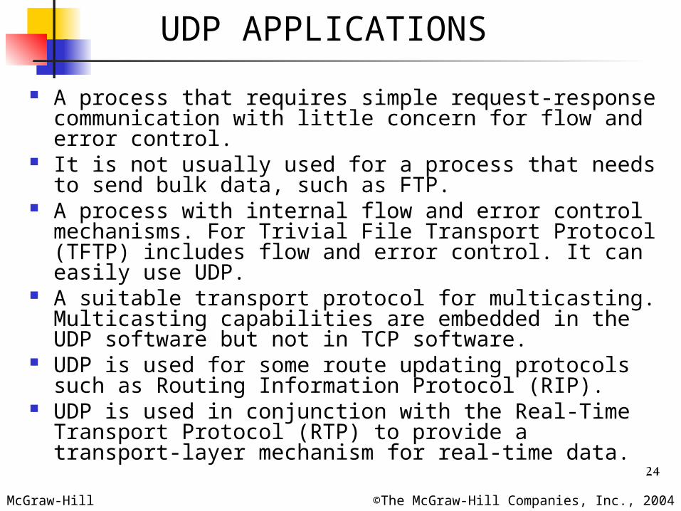
A process that requires simple request-response communication with little concern for flow and error control.
It is not usually used for a process that needs to send bulk data, such as FTP.
A process with internal flow and error control mechanisms. For Trivial File Transport Protocol (TFTP) includes flow and error control. It can easily use UDP.
A suitable transport protocol for multicasting. Multicasting capabilities are embedded in the UDP software but not in TCP software.
UDP is used for some route updating protocols such as Routing Information Protocol (RIP).
UDP is used in conjunction with the Real-Time Transport Protocol (RTP) to provide a transport-layer mechanism for real-time data.
UDP APPLICATIONS

25McGraw-Hill ©The McGraw-Hill Companies, Inc., 2004
Transmission Control Protocol (TCP)
Reliable protocol. Stream connection-oriented and reliable
transport protocol. Adds connection-oriented and reliability
features to the services of IP.
26McGraw-Hill ©The McGraw-Hill Companies, Inc., 2004
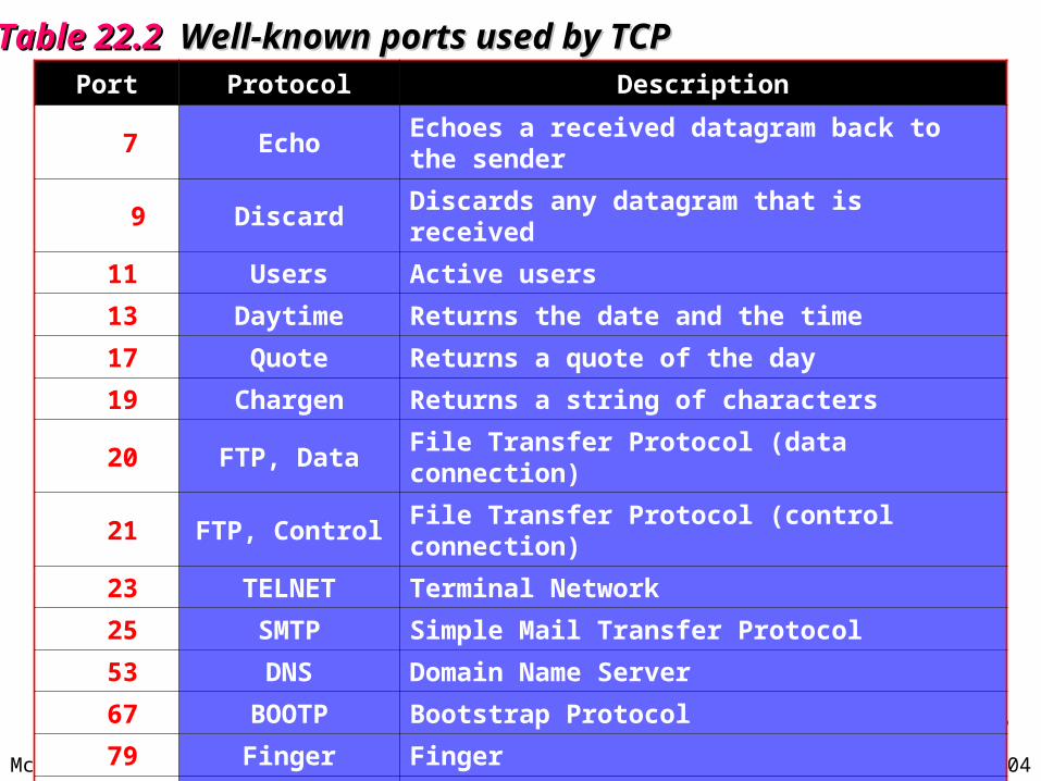
Table 22.2 Table 22.2 Well-known ports used by TCPWell-known ports used by TCPPort Protocol Description
7 Echo Echoes a received datagram back to the sender
9 Discard Discards any datagram that is received
11 Users Active users
13 Daytime Returns the date and the time
17 Quote Returns a quote of the day
19 Chargen Returns a string of characters
20 FTP, Data File Transfer Protocol (data connection)
21 FTP, Control File Transfer Protocol (control connection)
23 TELNET Terminal Network
25 SMTP Simple Mail Transfer Protocol
53 DNS Domain Name Server
67 BOOTP Bootstrap Protocol
79 Finger Finger
80 HTTP Hypertext Transfer Protocol
111 RPC Remote Procedure Call
27McGraw-Hill ©The McGraw-Hill Companies, Inc., 2004
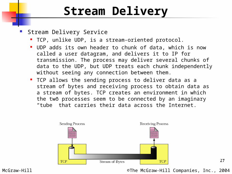
Stream Delivery
Stream Delivery Service TCP, unlike UDP, is a stream-oriented protocol. UDP adds its own header to chunk of data, which is now
called a user datagram, and delivers it to IP for transmission. The process may deliver several chunks of data to the UDP, but UDP treats each chunk independently without seeing any connection between them.
TCP allows the sending process to deliver data as a stream of bytes and receiving process to obtain data as a stream of bytes. TCP creates an environment in which the two processes seem to be connected by an imaginary “tube” that carries their data across the Internet.
28McGraw-Hill ©The McGraw-Hill Companies, Inc., 2004
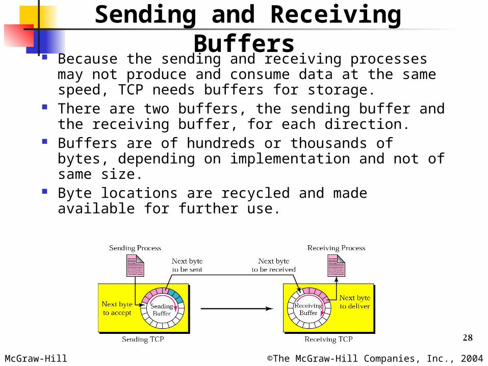
Sending and Receiving Buffers
Because the sending and receiving processes may not produce and consume data at the same speed, TCP needs buffers for storage.
There are two buffers, the sending buffer and the receiving buffer, for each direction.
Buffers are of hundreds or thousands of bytes, depending on implementation and not of same size.
Byte locations are recycled and made available for further use.
29McGraw-Hill ©The McGraw-Hill Companies, Inc., 2004
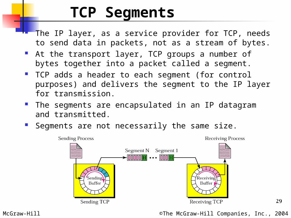
TCP Segments The IP layer, as a service provider for TCP, needs to send
data in packets, not as a stream of bytes. At the transport layer, TCP groups a number of bytes
together into a packet called a segment. TCP adds a header to each segment (for control purposes)
and delivers the segment to the IP layer for transmission. The segments are encapsulated in an IP datagram and
transmitted. Segments are not necessarily the same size.
30McGraw-Hill ©The McGraw-Hill Companies, Inc., 2004
A process at site A wants to send and receive data from another process at site B
A’s TCP informs B’s TCP and gets approval from B’s TCP A’s TCP and B’s TCP exchange data in both directions After both processes have no data left to send and
buffers are empty, the two TCPs destroy their buffers. Uses virtual connection and not physical connection TCP segments are encapsulation in IP datagram and so
can be sent out of order or lost or corrupted. TCP creates a stream-oriented environment in which it
accepts the responsibility of delivering bytes in order to the other side.
Connection Oriented Service
31McGraw-Hill ©The McGraw-Hill Companies, Inc., 2004
Numbering bytes Sequence number and acknowledgement number Byte number:
When TCP receives bytes of data from the process and stores them in the sending buffer; it numbers them.
Numbering does not necessarily start from 0; it starts with a randomly generated number between 0 to 232 – 1.
If random number happens to be 1057 and total data to be sent are 6000 bytes, the bytes are numbered from 1057 to 7056.
Sequence number TCP assigns a sequence number to each segment that is being
sent. Sequence number of each segment is the number of the first
byte carried in that segment. Acknowledgement number
Sequence number in each direction shows the number of first byte carried by the segment.
Each party also uses an acknowledgement number to confirm the bytes it has received. However, the acknowledgement number defines the number of the next byte that the party expects to receive.
Acknowledgement number is cumulative, which means that the receiver takes the number of the last byte it has received, safe and sound, adds 1 to it, and announces this sum as the acknowledgement number.

32McGraw-Hill ©The McGraw-Hill Companies, Inc., 2004
Example 1Example 1
Imagine a TCP connection is transferring a file of 6000 bytes. The first byte is numbered 10010. What are the sequence numbers for each segment if data are sent in five segments with the first four segments carrying 1000 bytes and the last segment carrying 2000 bytes?
SolutionSolution
The following shows the sequence number for each segment: Segment 1 ==> sequence number: 10,010 (range: 10,010 to 11,009) Segment 2 ==> sequence number: 11,010 (range: 11,010 to 12,009) Segment 3 ==> sequence number: 12,010 (range: 12,010 to 13,009) Segment 4 ==> sequence number: 13,010 (range: 13,010 to 14,009) Segment 5 ==> sequence number: 14,010 (range: 14,010 to 16,009)
33McGraw-Hill ©The McGraw-Hill Companies, Inc., 2004
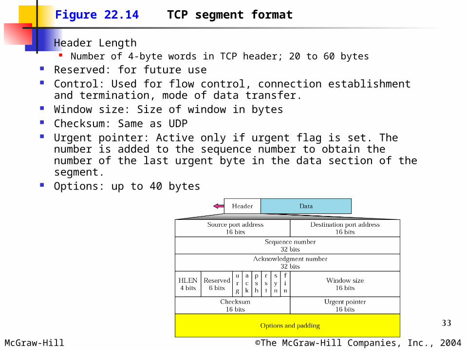
Figure 22.14 TCP segment format
Header Length Number of 4-byte words in TCP header; 20 to 60 bytes
Reserved: for future use Control: Used for flow control, connection establishment and
termination, mode of data transfer. Window size: Size of window in bytes Checksum: Same as UDP Urgent pointer: Active only if urgent flag is set. The number is
added to the sequence number to obtain the number of the last urgent byte in the data section of the segment.
Options: up to 40 bytes
34McGraw-Hill ©The McGraw-Hill Companies, Inc., 2004
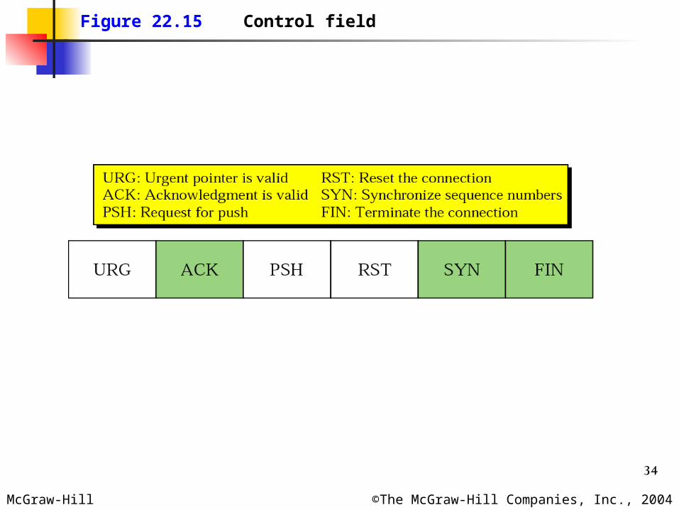
Figure 22.15 Control field

35McGraw-Hill ©The McGraw-Hill Companies, Inc., 2004
Table 22.3 Table 22.3 Description of flags in the control fieldDescription of flags in the control field
Flag Description
URG The value of the urgent pointer field is valid.
ACK The value of the acknowledgment field is valid.
PSH Push the data.
RST The connection must be reset.
SYN Synchronize sequence numbers during connection.
FIN Terminate the connection.
36McGraw-Hill ©The McGraw-Hill Companies, Inc., 2004
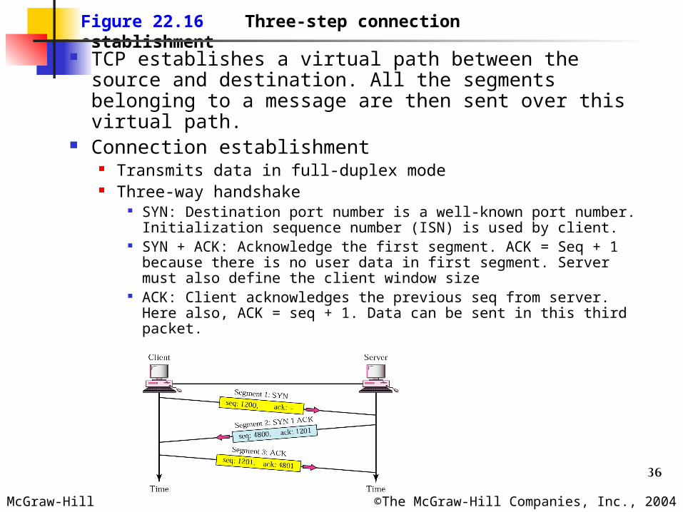
Figure 22.16 Three-step connection establishment
TCP establishes a virtual path between the source and destination. All the segments belonging to a message are then sent over this virtual path.
Connection establishment Transmits data in full-duplex mode Three-way handshake
SYN: Destination port number is a well-known port number. Initialization sequence number (ISN) is used by client.
SYN + ACK: Acknowledge the first segment. ACK = Seq + 1 because there is no user data in first segment. Server must also define the client window size
ACK: Client acknowledges the previous seq from server. Here also, ACK = seq + 1. Data can be sent in this third packet.

37McGraw-Hill ©The McGraw-Hill Companies, Inc., 2004
Figure 22.17 Four-step connection termination
Any of the parties involved in exchanging data can close the connection.
When connection in one direction is terminated, the other party can continue sending data in other direction.
FIN from client ACK from server for the FIN of client Data from Server; Once there is no more data to
be sent, server sends FIN ACK from client for FIN of server
38McGraw-Hill ©The McGraw-Hill Companies, Inc., 2004
Connection Resetting Resetting means that the current connection is
destroyed due to anyone of the following cases: TCP on one side has requested a connection to a
nonexistent port. The TCP on the other side may send a segment with its RST bit set to annul the request
TCP may want to abort the connection due to an abnormal situation. It can send an RST segment to close the connection
TCP on one side may discover that the TCP on the other side has been idle for long time. It may send an RST segment to destroy the connection.
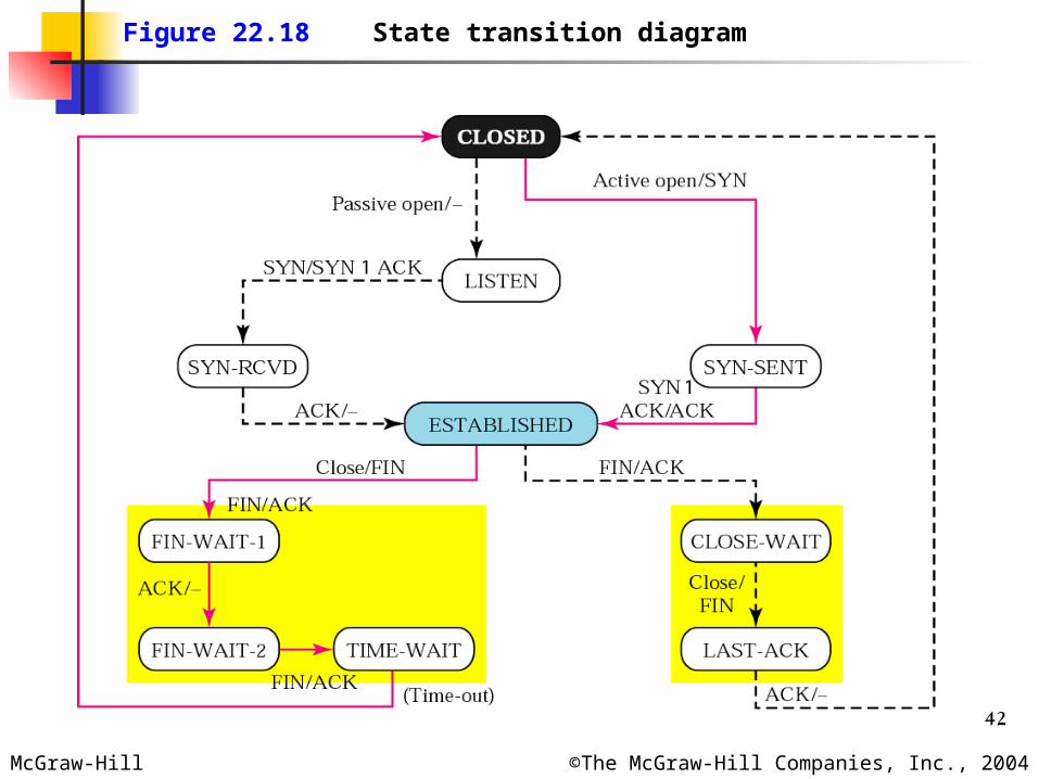
State Transition Diagram Finite state machine is a machine that goes through
a limited number of states. At any moment, the machine is one of the states. It
remains in that state until an event happens.
39McGraw-Hill ©The McGraw-Hill Companies, Inc., 2004
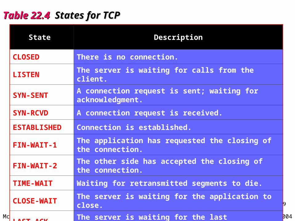
Table 22.4 Table 22.4 States for TCPStates for TCP
State Description
CLOSED There is no connection.
LISTEN The server is waiting for calls from the client.
SYN-SENT A connection request is sent; waiting for acknowledgment.
SYN-RCVD A connection request is received.
ESTABLISHED Connection is established.
FIN-WAIT-1 The application has requested the closing of the connection.
FIN-WAIT-2 The other side has accepted the closing of the connection.
TIME-WAIT Waiting for retransmitted segments to die.
CLOSE-WAIT The server is waiting for the application to close.
LAST-ACK The server is waiting for the last acknowledgment.
40McGraw-Hill ©The McGraw-Hill Companies, Inc., 2004
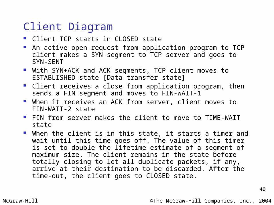
Client Diagram Client TCP starts in CLOSED state An active open request from application program to TCP
client makes a SYN segment to TCP server and goes to SYN-SENT
With SYN+ACK and ACK segments, TCP client moves to ESTABLISHED state [Data transfer state]
Client receives a close from application program, then sends a FIN segment and moves to FIN-WAIT-1
When it receives an ACK from server, client moves to FIN-WAIT-2 state
FIN from server makes the client to move to TIME-WAIT state When the client is in this state, it starts a timer and wait until
this time goes off. The value of this timer is set to double the lifetime estimate of a segment of maximum size. The client remains in the state before totally closing to let all duplicate packets, if any, arrive at their destination to be discarded. After the time-out, the client goes to CLOSED state.
41McGraw-Hill ©The McGraw-Hill Companies, Inc., 2004
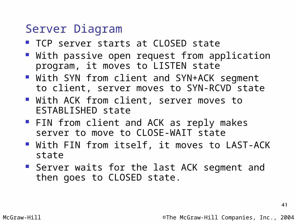
Server Diagram TCP server starts at CLOSED state With passive open request from application
program, it moves to LISTEN state With SYN from client and SYN+ACK segment to
client, server moves to SYN-RCVD state With ACK from client, server moves to
ESTABLISHED state FIN from client and ACK as reply makes server
to move to CLOSE-WAIT state With FIN from itself, it moves to LAST-ACK state Server waits for the last ACK segment and then
goes to CLOSED state.
42McGraw-Hill ©The McGraw-Hill Companies, Inc., 2004
Figure 22.18 State transition diagram

43McGraw-Hill ©The McGraw-Hill Companies, Inc., 2004
Figure 22.19 Sender buffer
Flow control Defines the amount of data a source can send before
receiving an acknowledgement from the destination. In an extreme case, a transport layer protocol could
send 1 byte of data and wait for an acknowledgement before sending the next byte. This would be an extremely slow process.
At the other extreme, a transport-layer protocol can send all the data it has without worrying about acknowledgement. But this would overwhelm the receiver. Also, handling lost or corrupted or duplicated packets would be difficult for the source.
TCP defines a window that is imposed on the buffer of data delivered from the application program and is ready to be sent.
44McGraw-Hill ©The McGraw-Hill Companies, Inc., 2004
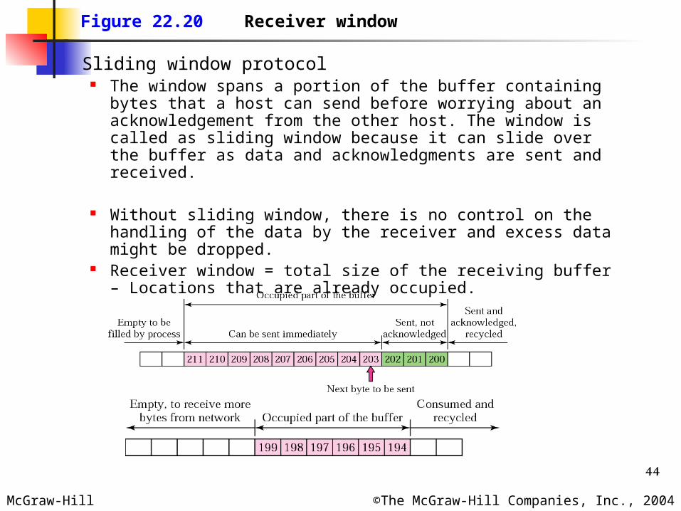
Figure 22.20 Receiver window
Sliding window protocol The window spans a portion of the buffer containing bytes
that a host can send before worrying about an acknowledgement from the other host. The window is called as sliding window because it can slide over the buffer as data and acknowledgments are sent and received.
Without sliding window, there is no control on the handling of the data by the receiver and excess data might be dropped.
Receiver window = total size of the receiving buffer – Locations that are already occupied.

45McGraw-Hill ©The McGraw-Hill Companies, Inc., 2004
Figure 22.21 Sender buffer and sender window
Flow control is present if the sender creates a window with size less than or equal to the size of the receiver window.
Number of bytes the sender can send is equal to the window size minus the number of bytes that have already been sent.
46McGraw-Hill ©The McGraw-Hill Companies, Inc., 2004
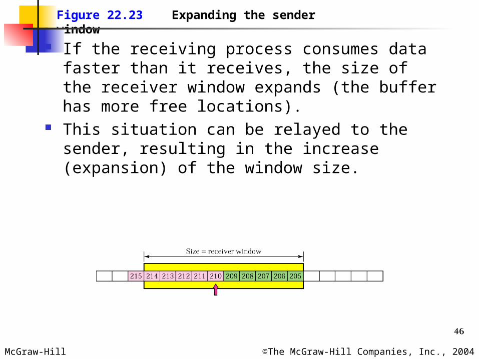
Figure 22.23 Expanding the sender window
If the receiving process consumes data faster than it receives, the size of the receiver window expands (the buffer has more free locations).
This situation can be relayed to the sender, resulting in the increase (expansion) of the window size.
47McGraw-Hill ©The McGraw-Hill Companies, Inc., 2004
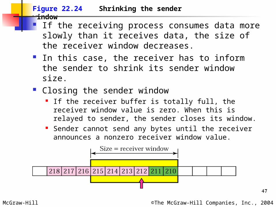
Figure 22.24 Shrinking the sender window
If the receiving process consumes data more slowly than it receives data, the size of the receiver window decreases.
In this case, the receiver has to inform the sender to shrink its sender window size.
Closing the sender window If the receiver buffer is totally full, the receiver
window value is zero. When this is relayed to sender, the sender closes its window.
Sender cannot send any bytes until the receiver announces a nonzero receiver window value.
48McGraw-Hill ©The McGraw-Hill Companies, Inc., 2004
Silly Window Syndrome If the sender or the receiver application program
processes slowly and can send only 1 byte of data at a time, then the overhead is high.
This is because to send one byte of data, 20 bytes of TCP header and 20 bytes of IP header are sent. This is called as silly window syndrome.
Syndrome by sender If the application program works slowly and writes one
byte at a time into the buffer. Here, instead of sending one byte every time, we wait to
accumulate a block and send. If it waits too long, it may delay the process. If it does not wait long enough, it may be up sending small segments.
Nagle’s algorithm First segment is sent as it is even if it is only one byte Wait for ACK from receiver [OR segment accumulation until
maximum-size segment] and till them accumulate data into the output buffer.
If the application program is faster than the network, the segments are larger (maximum-size segments). If the application program is slower than the network, the segments are smaller (less than the maximum segment size).
49McGraw-Hill ©The McGraw-Hill Companies, Inc., 2004
Syndrome by receiver Due to handling capacity of the receiver application
program and accumulation on the buffer. Clark’s solution
Send an ACK as soon as the data arrive, but to announce a window size of zero until either there is enough space to accommodate a segment of maximum size or until one-half of the buffer is empty.
Delayed acknowledgement Acknowledgement is delayed. Receiver waits until there is a decent amount of space
in its incoming buffer before acknowledging the arrived segments.
Delayed acknowledgement prevents the sending TCP from sliding its window.
Reduces traffic.

50McGraw-Hill ©The McGraw-Hill Companies, Inc., 2004
Error Control Checksum: Used to check for corrupted
segment. Corrupted segment is discarded by destination TCP
Acknowledgement: Confirm the receipt of those segments that have
reached the destination uncorrupted. No negative acknowledgement is used in TCP If a segment is not acknowledged before time-out, the
segment is considered to be either corrupted or lost. Source TCP starts one time-out counter for each
segment. Each counter is checked periodically. When a counter matures, the corresponding segment is considered to be either corrupted or lost, and the segment will be retransmitted.
51McGraw-Hill ©The McGraw-Hill Companies, Inc., 2004
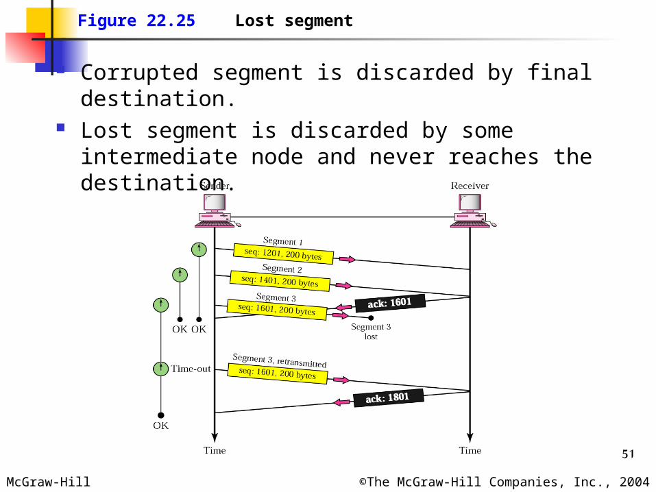
Figure 22.25 Lost segment
Corrupted segment is discarded by final destination.
Lost segment is discarded by some intermediate node and never reaches the destination.
52McGraw-Hill ©The McGraw-Hill Companies, Inc., 2004
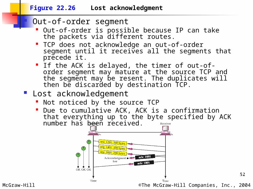
Figure 22.26 Lost acknowledgment
Out-of-order segment Out-of-order is possible because IP can take the
packets via different routes. TCP does not acknowledge an out-of-order segment
until it receives all the segments that precede it. If the ACK is delayed, the timer of out-of-order
segment may mature at the source TCP and the segment may be resent. The duplicates will then be discarded by destination TCP.
Lost acknowledgement Not noticed by the source TCP Due to cumulative ACK, ACK is a confirmation that
everything up to the byte specified by ACK number has been received.
53McGraw-Hill ©The McGraw-Hill Companies, Inc., 2004
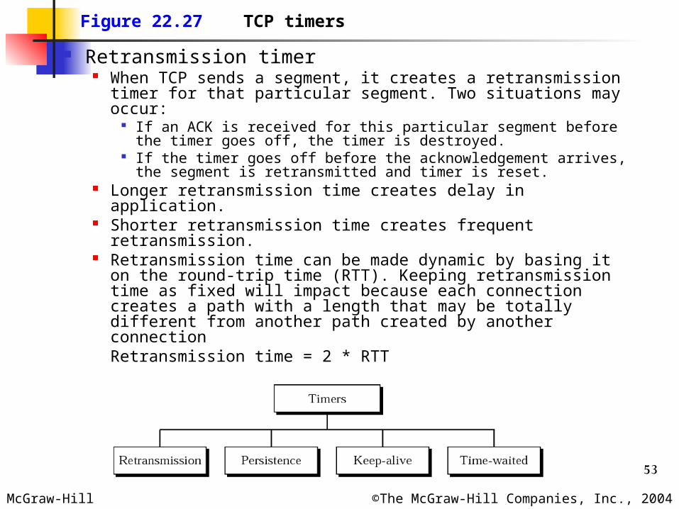
Figure 22.27 TCP timers
Retransmission timer When TCP sends a segment, it creates a retransmission
timer for that particular segment. Two situations may occur:
If an ACK is received for this particular segment before the timer goes off, the timer is destroyed.
If the timer goes off before the acknowledgement arrives, the segment is retransmitted and timer is reset.
Longer retransmission time creates delay in application. Shorter retransmission time creates frequent
retransmission. Retransmission time can be made dynamic by basing it
on the round-trip time (RTT). Keeping retransmission time as fixed will impact because each connection creates a path with a length that may be totally different from another path created by another connection
Retransmission time = 2 * RTT
54McGraw-Hill ©The McGraw-Hill Companies, Inc., 2004
Calculation of RTT First option: TCP uses the value from the timestamp option. Second option: TCP sends a segment, starts a timer, and
waits for an ACK. Measure the time between sending and receiving of ack.
Value of RTT used in the calculation of the retransmission time of the next segment is the updated value of the RTT according to the formula:
RTT = alpha (previous RTT) + (1-alpha) (current RTT)Alpha = 90%
Karn’s algorithm A segment is not acknowledged during retransmission period
and so it is retransmitted. Now if the acknowledgement arrives, we don’t know whether
this ack is for original or the retransmitted segment. Do not consider the RTT of a retransmitted segment in the
calculation of the new RTT Do not update the value of RTT until you send a segment
and receive an acknowledgement without the need for retransmission.

55McGraw-Hill ©The McGraw-Hill Companies, Inc., 2004
Persistent timer If the sender TCP receives an ACK of window size zero
it will wait for next ACK about change in window size. If the next ACK [which indicates the change in
window size] gets lost, both the TCPs will wait for forever. Acknowledgements are not acknowledged in TCP.
Persistent timer is started when the TCP receiver a window size zero ACK.
When this timer expires, it sends a probe message [one byte message] with a sequence number which is not acknowledged and which is not considered.
Probe alerts the receiving TCP that the ACK was lost and should be resent.
Value of persistent timer = Retransmission time. If a response is not received from receiver, send
another probe and double the persistent timer. This is done until a threshold (usually 60 sec). After threshold value, a probe is sent after every threshold.
56McGraw-Hill ©The McGraw-Hill Companies, Inc., 2004
Keep-alive timer To prevent a long idle connection between two TCPs. Suppose the client crashes after a long idle time. Each time the server hears from a client, it resets this timer. The
time-out is usually 2h. If the server does not hear from the client after 2h, it sends a probe segment. If there is no response after 10 probes, each of which is 75s apart, it assumes that the client is down and terminates the connection.
Time-waited timer Used during connection termination. When TCP closes a connection, the connection is held in limbo for a
time-waited period. This allows duplicate FIN segments, if any, to arrive at the destination to be discarded.
Pushing data Application program on the sending site can request a push
operation. Application program can instruct the sending TCP to send the data
before completion of the window. Sending TCP can also set the Push bit (PSH) to tell the receiving TCP
that the segment includes data that must be delivered to the receiving application program as soon as possible and not to wait for more data to come.
Now a days, TCP can choose whether to use this operation, even if the application program requests for it.
Ex. When an application wants data to transferred on keystroke and not when the window to be filled.
57McGraw-Hill ©The McGraw-Hill Companies, Inc., 2004
Urgent data There are occasions in which an application program
needs to send urgent bytes. The application program wants a piece of data to be
read out of order by the receiving application program. Sending application tells the sending TCP that the piece
of data is urgent. The sending TCP creates a segment and inserts the urgent data at the beginning of the segment. The rest of the segment can contain normal data from the buffer. The urgent pointer field in the header defines the end of the urgent data and the start of normal data.
When the receiving TCP receives a segment with the URG bit set, it extracts the urgent data from the segment, using the value of the urgent pointer, and delivers it, out of order, to the receiving application program.
Ex. When an application has sent some wrong data and it wishes to issue Contrl+C to abort the operation.