MBBR OM Manual-250
42
1 OPERATION AND MAINTANANCE MANUAL FOR EEC HIGH SPEED BIO TEC SYSTEMS MODEL 33CON 3 2*250 m3/day SEWAGE TREATMENT PLANT FACILITY SABAA AKBAR IRAQ SUBMITTED BY E.T.A. Zenath ENVIRONMENTAL ENGINEERING SERVICE LLC. POST BOX NUMBER 7113 DEIRA, DUBAI. United Arab Emirates Tel: +9714-2713006 Fax: +9714-2713487 Email: [email protected] www.etazenath.com www.eecme.com
-
Upload
senthil2002 -
Category
Documents
-
view
342 -
download
13
Transcript of MBBR OM Manual-250

1
OPERATION AND MAINTANANCE
MANUAL FOR EEC HIGH � SPEED BIO TEC SYSTEMS MODEL 33CON 3
2*250 m3/day SEWAGE TREATMENT PLANT
FACILITY
SABAA AKBAR
IRAQ
SUBMITTED BY E.T.A. Zenath ENVIRONMENTAL ENGINEERING SERVICE LLC.
POST BOX NUMBER � 7113
DEIRA, DUBAI. United Arab Emirates
Tel: +9714-2713006 Fax: +9714-2713487 Email: [email protected]
www.etazenath.com www.eecme.com

2
CONTENTS SECTION 11.. CCOOMMPPAANNYY PPRROOFFIILLEE
22.. IINNTTRROODDUUCCTTIIOONN
33.. DDEESSIIGGNN BBAASSIISS
44.. WWAATTEERR AANNAALLYYSSIISS
55.. PPRROOCCEESSSS DDEESSCCRRIIPPTTIIOONN
66.. SSYYSSTTEEMM OOPPEERRAATTIIOONN
77.. CCOOMMPPAARRIISSOONN DDAATTAASSHHEEEETT
88.. BBIILLLL OOFF MMAATTEERRIIAALLSS
99.. TTEECCHHNNIICCAALL DDAATTAASSHHEEEETTSS && CCAATTAALLOOGGUUEESS
1100.. DDRRAAWWIINNGGSS 1111.. TTRROOUUBBLLEE SSHHOOOOTTIINNGG GGUUIIDDEE
1122.. MMAAIINNTTAANNCCEE SSCCHHEEDDUULLEE

3
1. Company Profile

4
PROFILE
EEC - ME, a part of the large and diversified ETA-Ascon, a 30 years old group, again
part of Al Ghurair Group. Also, we present you with our professional team of people,
which has provided you with the best technical and professional assistance for a total
waste management / water treatment program, especially in the field of desalination
(RO), sewerage and industrial water along with the most reputed and specialized
American and European companies in this field. EEC - ME fields of concentration
are:
1 Industrial Water: We provide you with the design study and installation for most if not all-industrial water treatment. This water for the most part can be recycled back into the plant and can make tremendous saving to the companies.
2 General and Sewerage Water: This water can be treated for irrigation use, or some of it can be circulated back into the bathrooms for flushing purposes- saving hotels and labor camps a lot of money.
3 Desalination and Brackish Water Treatment: If you are looking for fresh,
potable water, EEC - ME can provide you a Membrane desalination plant designed to your particular needs and requirements. This can be either Seawater or Well Brackish Water.
4 Total Waste Management: EEC - ME with corporation with other ETA
divisions and other international companies can provide you with design implementation and operation of a total waste management for your community or city.

5
EEC - ME are joining hand with a list of specialist and reputed companies in the field of
water treatment from USA and Finland such as, Environmental Equipment Consulting,
EEC, USA; Enviro-Chemie, Germany; IPM, Germany. With our extensive experience in
the Environmental / Water Treatment field in the USA, coupled with long and acclaimed
work history of ETA-Ascon Group and the help of the group of specialist with which we
have joined, we believe we provide Companies / Industries in the Middle East with the
best, most economical way for a total water and waste water management.

6
2. Introduction
7
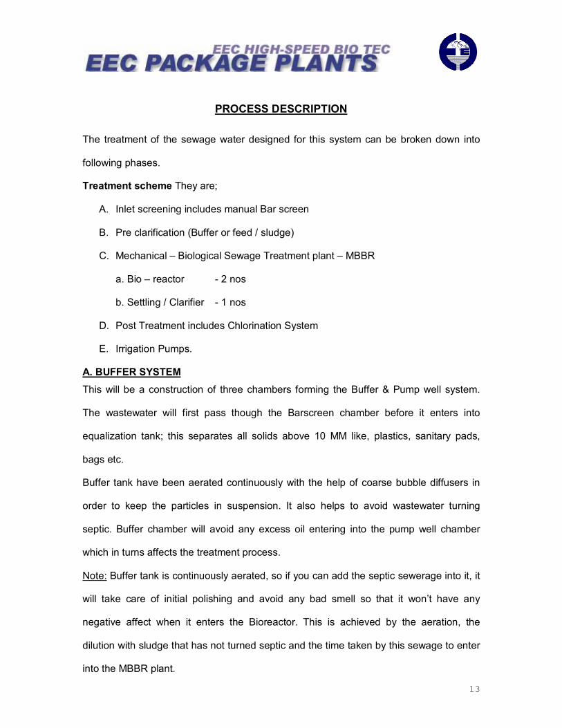
INTRODUCTION
The ever stricter requirements that industry around the globe has to meet in regard to
the use of the natural resource water are boosting the demand for profitable, low-cost
and highly efficient sewerage / waste water treatment systems. Copying nature�s
fascinating capabilities as perfectly as possible and harnessing them for our technical
applications is the source of innovative renewal processes. Nature shows us in an
exemplary manner that organic matter contained in water can be converted biologically
into energy-rich and utilizable.
EEC ME shall provide you an efficient, cost effective, time saving solution for any water
needs, especially the waste and sewage treatment systems. AMB BIOMEDIA ensures
that the system footprint is five times smaller and ten times faster than regular treatment
plants.

8
3. Design Basis

9
DESIGN BASIS
The basic design and the processes use stichomythic factors to alter the concentrations
of the materials involved. As a result of the high level of process linkage, a material can
be of decisive importance to several processes in the model. Should an alteration in the
concentration of this material occur due to one process, and then the processing speed
of another will be influenced, which in turn, has consequences for the entire system.
We have assumed wastewater fully domestic in character from residential application
and that metal contents documented in the consent for discharge would not be present
in any higher amount in the influent and therefore will not present in the effluent. Based
on this assumption we have not allowed for any removal of inorganic material and metals
from the wastewater. We have also assumed the 2*250 m3/day in the residential area
and have allowed a flow of 200 liter per person per day and BOD of � 300 mg/liter in the
influent.

10
4. Water Analysis

11
WATER ANALYSIS
Flow Profile 1. Capacity 2*250 m3/day 2. Max. Hourly flow 2*11.36 m3/hr 3. Peak flow factor 2.5 4. Plant offered 2*33 con 3 (Max Capacity � 600m3/day) Influent Parameters of Waste water 1. Nature of influent Raw Domestic Waste Water
2. BOD5s 350 � mg/l
3. COD 500 � mg/l
4. Total Suspended Solids 300-400 � mg/l
Quality of Treated Water 1. BOD Less than or equal to 20 mg/l
2. TSS Less than or equal to 30 mg/l
3. pH 6 � 9

12
5. Process Description
13
PROCESS DESCRIPTION
The treatment of the sewage water designed for this system can be broken down into
following phases.
Treatment scheme They are;
A. Inlet screening includes manual Bar screen
B. Pre clarification (Buffer or feed / sludge)
C. Mechanical � Biological Sewage Treatment plant � MBBR
a. Bio � reactor - 2 nos
b. Settling / Clarifier - 1 nos
D. Post Treatment includes Chlorination System
E. Irrigation Pumps.
A. BUFFER SYSTEM This will be a construction of three chambers forming the Buffer & Pump well system.
The wastewater will first pass though the Barscreen chamber before it enters into
equalization tank; this separates all solids above 10 MM like, plastics, sanitary pads,
bags etc.
Buffer tank have been aerated continuously with the help of coarse bubble diffusers in
order to keep the particles in suspension. It also helps to avoid wastewater turning
septic. Buffer chamber will avoid any excess oil entering into the pump well chamber
which in turns affects the treatment process.
Note: Buffer tank is continuously aerated, so if you can add the septic sewerage into it, it
will take care of initial polishing and avoid any bad smell so that it won�t have any
negative affect when it enters the Bioreactor. This is achieved by the aeration, the
dilution with sludge that has not turned septic and the time taken by this sewage to enter
into the MBBR plant.

14
B. BIOLOGICAL TREATMENT SYSTEM The treatment plant will take suction from the pump well by its own feed pump. The
pump is level controlled and has a capacity, which is 2 times the average daily flow. The
plant has therefore intermittent working mode in terms of hydraulic flow, while the air
blower supplying air to the bioreactor is continuously running.
The biodegradation reactor comes in three stages. The bioreactors degrade the
dissolved organic matter by oxidation into carbon di oxide, which escapes to the air, and
also a biomass, which acts as an activated sludge. A suspended, free-floating bio film
carrier provides a large protected surface as host for the bacteria and simultaneously
active bio sludge accumulates inside the reactors.
The biodegraded water flows into a clarification chamber where the suspended solids
settle by gravity. The water is directed through a skim well to a Tube settler system,
which provides the final clarification of the effluent. An addition of polymer to the
sedimentation may enhance the cleaning/ settling efficiency if it is required.
C. SLUDGE SEPERATION SYSTEM
The sludge pump will be activated for approximately 5 minutes for every 1 hrs of
operation with suction from the clarification stage. The pump causes the discharge of the
sludge through a hydrocyclone, which separates volatile and non volatile solids with an
overflow back to the bioreactor, while the underflow is discharged to the Equalization
tank. Feed pump will stop whenever sludge pump is working. When necessary, the
sludge is emptied by a vacuum truck and hauled away for disposal.

15
6. System Operation

16
SYSTEM OPERATION
Moving Bed Process Technology Using AMB Bio Media. Description of the moving bed process
The basic principal of the moving bed process is the growth of the biomass on plastic
supports that move in the biological reactor via agitation generated by aeration systems
(aerobic reactors) or by mechanical systems (in anoxic or anaerobic reactors). The
supports are made from plastic with a density close to 1 g/cm3 letting them move easily
in the reactor even when the capacity reaches 70%.
The moving bed processes come from the current trend in wastewater treatment, from
the use of systems that offer an increased specific surface in the reactor for the growth
of the biomass, achieving significant reductions in the biological reactor volume.
Initially fixed bed systems were used, however it was discovered that this type
of process show a series of operational inconveniences such as the blocking of the bed
because of the excessive growth of the biomass, this makes periodical cleaning
obligatory. These drawbacks have caused the need for the creation of simple biofilm
processes that eliminate them and that ease their operation; these are the moving bed
processes.

17
This type of process can be applied both to treatment plants for the biodegradation of
organic material as well as for installations with nutrient elimination, in urban and
industrial wastewaters. Another application is the use of this technology in the redesign
of current activated sludge processes, which only treat organic material, to expand them
and include simple nitrogen elimination without the need to construct new biological
reactors.
With respect to the aeration system is via a grid of perforated stainless steel tubes that
avoid problems of efficiency loss, diffuser replacement, etc.
All the wastewater is collected in a 3 chamber Equalization tank. This tank acts as a
balancing reservoir, keep the wastewater in suspension and bar screen used to
separate solids, paper and other waste to be received with the wastewater. The last
chamber of this tank is fitted with a level control system, which starts or stops the
system feed pump. The feed pump takes suction from the last and discharges in to the
first chamber of the High-Speed Bio Tec.
The first and the second chamber of the High-Speed BioTech are filled with AMB Bio
media and water. The last chamber, which is a Tube settler, is filled with water only.
Before starting pumping of wastewater, the system blower starts. The blower forces air
through the manifolds into the first 2 chambers of the bio system and the equalization
chamber.
The influent wastewater enters the first chamber and comes in constant with the AMB
Bio Media and air Large Surface area provided by the AMB Bio Media helps the
bacteria to form large colonies on the AMB Bio Media. Slow circular motion of the
media is caused by the airflow. Each element of the media slowly moves in a circular

18
motion from the surface to the bottom and then upward again. During this movement, it
is in constant with the injected air, slowly a bio film develops over each element, which
disintegrates the biomass present in the effluent.
From the first chamber the effluent flow to the second chamber through the perforated
partition at the top. The same treatment is repeated in this chamber and the remaining
biomass from the first chamber gets fully digested here, effluent at this stage will go to
the 3rd Biodegradation chamber. The treated water then enters the third chamber at the
top.
A baffle plate guides the water entering the third chamber downwards. Then enters the
tube settler from the bottom. The settler provides a large surface area for the
suspended particles to settle down on its surface and the same area guided towards
the bottom. Clean water is let out of the system from the outlet provided at the top of
the third chamber.
When the level of the influent drops in the collection tank the feed pump gets tipped.
Simultaneously the sludge pump is started. The sludge pump draws sludge from the
bottom of the 3 chambers and discharges it into a Hydro-cyclone separates our heavier
sediments from the sludge, which settles in the collection tube mounted at the bottom of
the hydro-cyclone. Clarified water is discharged back into the first chamber of the
bioreactor. The sludge pump operates for pre-set time and is stopped automatically.

19
The solid sludge accumulated in the sludge collection tube is discharge out periodically.
This sludge can be used as manure or for land farming.
High-Speed Bio System should not compare with regular job systems (activated sludge)
as we implemented a leading technology known as �Assisting Moving Bed� or AMB Bio
Media. These systems are designed to handle sewer (black and Grey water) and most
biological wastewater from industrial application.
The AMB Bio Media represents 850 sqm / cum active area once submerged inside the
bio chambers. Activated sludge process and other bio film systems have often proven to
the unstable and difficult to control. By implementing the AMB Bio Media, your benefits
are numerous including reliable and compact bioreactors. The systems are self-
cleaning, non-clogging, can handle server BOD loading, pH variations, and colder
temperatures than regular systems, all this without loss of bioactivity. No sludge return
as in activated sludge system and our systems require minimum service and almost no
attention.

20
7. Manual Description

21
MANUAL DESCRIPTION
This manual describes the function, operation procedures, maintenance, and installation
requirement for the HIGH-SPEED BIOTECH reactor.
NOTES, CAUTIONS and WARNINGS are included in the Operating Procedures. They
should be interpreted as follows:
"NOTE� indicates an operating procedure or condition that is essential to highlight or
which provides a given procedure.
"CAUTION" indicates an operating procedure or practice that, if not strictly observed,
may result in damage to or destruction of equipment, or degradation of the water quality.
"WARNING" indicates an operating procedure or practice that can result in bodily injury
or loss of life if not correctly followed.
NOTES, CAUTIONS and WARNINGS always precede paragraphs to which they apply.
Under normal operating conditions, adherence to the procedures described in this
manual will assure trouble -free operation.

22
8. Installation & Start up

23
INSTALLATION OF HIGH SPEED BIO-TECH REACTOR The High Speed BIOTECH Bio reactor containers require properly leveled ground,
preferably concrete slab with drain facility or properly graveled. The High Speed
BIOTECH reactor must be carefully water leveled before commissioning and checked for
deviation afterwards. Otherwise national safety regulation must be adhered to. A
wastewater pond or buffer tank should be provided upstream of the plant. The pond
should be sized as to level out daily variation in hydraulic load and is to be arranged for
returns of reject water from the plant.
Downstream sludge receiving tank or pond must be provided, the daily produced sludge
and the haul away regularity determine the size of which. Local regulations with respect
to handling and disposal of sludge will determine any further treatment of the sludge.
WARNING
A qualified electrician in accordance with pertinent codes and regulations must perform
electrical installation and connection to the main power source. Turn off facility power
before making any electrical connections. System must be grounded in accordance with
applicable electrical codes.
24
THE AMB-BIOMEDIUM
The AMB bio film mediums are a proprietary bio medium. The Bio medium is produced
of plastic material, which has long lifetime in water. Renewal of the Bio medium during a
treatment plant's regular lifetime should normally not be required.
The bio film carrier elements are extruded tube cuttings with an internal cross and have
25 external low fins. Nominal measurements are Diameter 1/2�, Length 3/8�. The surface
to volume ratio is approx. 850 m² per m3 of Bio medium in bulk.
25
BIOMEDIUM FILLING PROCEDURES (Only applicable for media delivered in bags and separate from system.)
Preparations
Before filling-up and start-up the following preparations to be done:
1. Check that the air holes in the Spurger pipes are facing downwards. If not, drill ½
inch drain holes in each end of the spurges.
2. Check that the bulkhead strainers are positioned correctly and sufficiently secured
3. Check that there are no openings outside the strainers that the biomedia can
penetrate and also no passage for biomedia above the bulkheads where biomedia
can be carried over by eventual foaming. Any gaps to be less than ½�.
4. Start the air blower(s) against open-air valves, and throttle gradually. Listen for
unexpected noises from motor and housing. Run finally the blower(s) against closed
valves for a short time and note the discharge pressure. The discharge pressure
should be not less than 1.5 times the operating water head.
5. Fill the bio reactors with ½ of water, run the air blower from zero to low capacity and
check that the air diffusers are delivering equal and uniformly distributed amount of
air from each Spurger.
6. Start and run the sludge pump in recirculation mode, with successive suction from all
drain valves. Check that the flow is equal from each drain. Checks that the drain
suctions in the bioreactor tanks are enclosed in strainers to prevent biomedia from
entering the pump suction.
7. Start the feed pump with closed discharge valve and note the pump pressure. Open
the discharge valves fully and note full flow and discharge pressure.
8. Start the chemical pumps on water and check capacity.

26
Charging of biomedia
New Bio medium will repels water and must go through a wetting procedure before it will
properly mix in water:
1. Add wastewater to until overflow to the settling tank. Start up the blower(s) and
aerate moderately with ¼ to ½ of normal capacity.
2. Fill biomedia until the bulkhead screens are covered. Aerate continuously during the
filling.
3. Top up with remaining biomedia as space allows. If actual filling degree in the
reactors is 50% or less, then the whole amount of biomedia can be filled in one
charge.
4. Continue aeration until good mixing is obtained, meaning visible movement of
biomedia in the surface.
5. Charge more wastewater while recirculating from the settling tank. When the settling
tank is filled, increase aeration as the water level is increasing in all tanks. Aerate
moderately, just enough to have the media circulating in the reactors.
NOTE
Good mixing is normally obtained after 2 - 3 days on usual municipal wastewater. In the
beginning there will be an almost immobile blanket of biomedia on the surface, while
there will be a good mixing below this blanket and down to the bottom.

27
START UP PROCEDURES
When the media wetting procedure is completed, the reactors are ready for start
up
Municipal wastewater will contain sufficient degrading type bacteria to develop a healthy
bioculture in the reactors without being specifically seeded. Hence, during wetting, the
bioculture will already have started to grow. This can be observed visually by a slight
change in turbidity and pH, usually 1-2 days after completion of wetting.
1. Run the plant on recirculation for 1 or 2 days after wetting. Use the feed pump
instead of the sludge pump. Note the pH and observe any changes. The pH will
first go down during the acidic stage, and then up again as the degradation is
being completed.
2. When the pH is on way back to its initial value, add more wastewater. Change to
recirculation with the sludge pump and shift feed pump suction to the feed tank.
Add a volume corresponding to approx. 1/3 of the total volume.
3. Changes back to recirculation with the feed pump and observe pH again. Repeat
above procedures, and observe the time between each charging.
4. When the time between charging is decreasing, the plant is ready for continuous
operation.

28
BIOFILM GENERATION Time for generation of a bio film on the carrier elements will vary depending on type of
wastewater and the temperature:
Municipal wastewater 3 - 4 week
Food industry 1 - 2 weeks
Paper/pulp industry 3 - 4 days
As time goes by, the bio film will develop and become more efficient and robust. It will
reach its maximum capacity after one year of normal operation.
FOAM CONTROL
During start-up of bioreactors, when establishing bio film on the plastic elements,
foaming may occur. Also greater load variations in fully developed reactors may result in
foaming.
Foaming is caused by surface tensions in the wastewater. Reducing aeration and waste
charging reduces foaming during start up. Foaming in a started reactor is reduced by
combined recirculation and feeding. Foaming in a correctly dimensioned bioreactor,
running on municipal wastewater should normally not occur. However, the wastewater
may contain substances, which make foaming unavoidable.
Sustained foaming during operation may be controlled either by spraying or by chemical
injection. Any available antifoam agent will normally do.

29
SHUT-DOWN AND RESTART
If it becomes necessary to stop the load on the bioreactors for a shorter period, for
instance one-week, all reactors should be moderately aerated to keep aerobic biomedia
condition.
If it becomes necessary to stop the load on the bioreactors for a longer period, it is
recommended to aerate the reactors the first week after the stop, and to restart aeration
2 days before the reactors are re-loaded with organic matter.
Before wastewater again can be pumped to the biological stage, it is important that all
the biomedia is in good suspension in all bioreactors first.
NOTE
Always remember first to stop and start the aeration before stop and start the water
flow.

30
COMPARISON OF ACTIVATED SLUDGE / SBR PROCESSES TO HIGH SPEED BIO TECH PROCESS.
FEATURES ACTIVATED SLUDGE
PROCESSES / SBR PROCESSES
HS HIGH SPEED BIO TEC.
AMB BIO ELEMENTS NON CLOGGING MEDIA
Footprint Large Small or 1/5
Sludge return required Yes-sludge Bulking No-no sludge Bulking
High BOD Loading Sensitive Not sensitive to high BOD
Size Not Modular Modular
Containerized No Yes
Sensitive to pH Yes No
Sensitive to Cold
Temp. Yes Less Sensitive
Stabile/Robust
Operation
No Yes
Pre assembled ready
to go Large Number Max 10,000
Service Demanding No Yes
Clogging Yes No* Guaranteed Clog free
Central Operation
including
All Valves and Pumps
Depend on design
Standard
Labor Intensive
Installation Yes No
Shipping Coat High Low
Quick Start up 3 months 1-4 Weeks
Sludge Production Yes Empty once a year
Require backwash Yes No
Retention Time 20 Hours 5 Hrs

31
• Service: Require one man once a day to inspect system.
The High Speed Bio Tec are proven to be very stable and self-adjusting even under
harsh conditions, where most biological plants will shut down, and start to polluting the
environment (due to non-bio-activity). The High Speed Bio Tec with AMB Media secures
stabile and non-clogging reactors. Learn more about the system at www.eecme.com

32
9. Trouble Shooting

33
Trouble shooting:
S.no Process Cause Solution
1. Floating Sludge 1. Inefficient timing of sludge remove 2. Inefficient aeration
1.Check the sludge in buffer and holding tank 2. Check the aeration and airflow/blower.
2. High Suspended solids Inefficient Sludge removal Check the sludge removal timing.
3. Low Feed in the out put May cause floating Sludge Control the flow
4. High Feed in the out put High Suspended solids high TSS and high BOD
Control the flow
5. Foaming 1. Due to detergent in the laundry water 2. Due to high BOD in feed.
1. Check the incoming water 2. Do recirculation and spray clear water.
6. Chlorination BOD could be high at Sampling point.
Check the chemical dosage and the chemical tank
7. Blockage at the inlet Overflow at the manual screen and no flow into the equalization tank.
Remove the blockage at the barscreen

34
TO DO ! To follow the guidelines provided in the Operation Manual for proper starting and
shut down of the plant. ! The plant to be operated by the trained and experienced personnel. ! To check the line of the feed flow bar screen if any particles obstructing the flow. ! To check for any abnormality of Air blower, pumps ! To monitor the system pressure at different stages of the process as per the
recommendation provided in the Operation Manual. ! To keep proper record keeping such as daily operational log sheets, review the plant
status, recording of daily events, activities carried out and to maintain the equipment history record to carry out necessary service in time.
! Always maintain minimum inventory of original spares and regular consumables to
reduce down time of the plant equipment�s.
DO NOT:
# Not to stop the plant more than 90 mins.
# Never stop the Air blower of the plant for more than 2 hr. Bacterial colonies will be
affected.
# Not to open and dismantle the plant during the Warranty Period without prior information to the manufacturer.
# Not to use duplicate spare parts/regular consumables, which may impair the long life
of system and its equipment. Maintenace of Manual Barscreen: Bar screen will stop solids, plastics and other non volatile solids which are more than 12 mm entering into the Buffer tank.
The screen rack is removable type. Every week the operator has to remove the rake and wash with fresh water. In case of Grinder submersible pumps used at Lift station. Use of Bar screen is minimized or almost nil.
Note: The list provided above is provided as a quick guideline. It should not be considered as �complete� and exhaustive� information on system operation.

35
10. Bill of Materials

36
BILL OF MATERIALS
SNO Description Quantity 1. Feed Pump 2 Nos. 2. Sludge Pump/ Recirculation Pump 2 Nos. 3. Hydro cyclone 2 Nos. 4. Air Blower: Regenerative type 2 Nos. 5. Bio �Reactor Tank with 3 chamber in MSEP 2 Nos. 6. Float level Switch 2 Nos. 7. Control Panel for the plant 1 No. 8. Bio Media 1 lot 9. Tube setter Media 1 lot
10. SS piping and fittings 1 lot 11. PVC fittings and piping 1 lot 12. Electrical cable and accessories 1 lot 13. Junction Box 2 Nos. 14. Diffuser 27 Nos. 15. Flow Meter 1 Nos. 16. Dosing Pump 4 Nos.
BILL OF MATERIALS (SPARES) SNO Description Quantity
1. Feed Pump 1 No. 2. Sludge Pump/ Recirculation Pump 2 No. 3. Air Blower: Regenerative type 1 No. 4. PVC ball valves 4 Nos. 5. Pressure gauge 2 Nos. 6. Float Level Switch 1 No 7. Dosing Pump 1 No.

37
11. Data sheets & Catalogues

38
TECHNICAL DATASHEETS
EQUIPMENT SUBMERSIBLE FEED PUMP DESCRIPTION VALUE Technical: Maximum flow: 40m3/h Head max: 20.8m Type of impeller: VORTEX Type of primary shaft seal: SIC/SIC Type of secondary shaft seal: CARBON/CERAMICS Approvals on nameplate: PA-I Model No: SEV.65.65.30.2.50D Made: GRUNDFOS, DENMARK Materials: Pump housing: Cast iron GS20 Impeller: ` Cast iron GG20 Installation: Maximum ambient temperature: 40°C Maximum operating pressure: 10bar Maximum installation depth: 20m Liquid: Temperature range: 0-40°C Electrical data: Number of poles: 2 P1: 3.8kW P2: 3kW Frequency: 50Hz Rated voltage: 3*380-415V Stating method: direct-on-line Rate of speed: 2910 rpm Motor protect: THERMAL SWITCH Pump weight 95Kg Catalogues Attached Curves Attached

39
TECHNICAL DATASHEETS
EQUIPEMENT SLUDGE / RECYCLE PUMP
DESCRIPTION VALUE Technical: Maximum flow: 15.2m3/h Head max: 22.3m Actual impeller diameter: 130 mm Type of shaft seal: BAQE Pump version: A Model No: NBG 50-32-125/130 Made: GRUNDFOS, HUNGARY. Materials: Pump housing: Cast iron EN-JL1040 DIN W.-Nr. A48-40B ASTM Impeller: ` Cast iron EN-JL1030 DIN W.-Nr. A48-40B ASTM Installation: Maximum ambient temperature: 40°C Maximum operating pressure: 16bar Liquid: Temperature range: 0-120°C Electrical data: Motor type 90LA Number of poles: 2 P2: 2.2kW Frequency: 50Hz Rated voltage: 3*380-415V Rate of speed: 2860-2890 rpm Pump weight 54 Kg Catalogues Attached Curves Attached

40
TECHNICAL DATASHEETS
EQUIPMENT REGENERATIVE AIR BLOWER
DESCRIPTION VALUES
Tag RB - 1
Manufacturer RKR - Germany
Quantity 3 No.
Mode of working 2 Working (1 Spare Loose)
Type Roots Type (Three Lobed)
Model No BLP 15-15
Nominal Capacity 590 m3/hr
Back Pressure 450 m bar
Motor Rating ISO, F Class
Material of Construction SS / CI
Sound pressure Level 91 dB
Discharge connection DN 100
RPM 2440 RPM
Phase 3
Power Rating 18.5 KW
Voltage (Delta/Star) 400 /690 V AC
Current Supply 12 / 7 A
Weight 165 Kgs. Approx.
Catalogues Attached
Curves Attached
Spare List Attached

41
DATASHEET FOR HYDROCYCLONE
DATA DESCRIPTION
ITEM HYDROCYCLONE
Manufacturer LAKOS, USA
Quantity 2 no
Model ILB 0100
Working Mode 1 No Working
Mode of service Manual
Service Sewerage water
Application Removal of solids from liquids or vice versa
Body Carbon steel / stainless steel
Coatings Epoxy
Connections Flanged / Threaded
Working Pressure 2 Bar
Max. Working Pressure 10.2 Bar
Pressure loss range 0.31 � 0.82 Bar
Process flow rate 8 m3/hr.
Working Temperature Ambient
Catalogues Attached
GA drawings Attached

42
DATA SHEET FOR CABLES
DATA DESCRIPTION
ITEM ARMOURED CABLES
Manufacturer DUCAB, DUBAI
Service Feed Pump Armored
Recirculation Pump Armored
Regenerative blower Armored
Control Panel Un Armored
Level Switches Un Armored
Type of the cables Multi core / single core
Size As per the power rating
Accessories Cable Glands
Cable Ferrules
Cable Markers
Junction Boxes (If Required)
Catalogues Attached