Maytag MAH3000AWW Service Manual
157
16010061 Compiled From 16008373, 16010199, Customer Service TM Washer Serv ice Ma nual Washer Service Manual 16010886 11/03
-
Upload
barryfield -
Category
Documents
-
view
244 -
download
8
Transcript of Maytag MAH3000AWW Service Manual

8/3/2019 Maytag MAH3000AWW Service Manual
http://slidepdf.com/reader/full/maytag-mah3000aww-service-manual 1/157
160100Compiled
16008373, 160
Customer Service
TM
Washer
Service Manua
Washer
Service Manua
16010886 11/0

8/3/2019 Maytag MAH3000AWW Service Manual
http://slidepdf.com/reader/full/maytag-mah3000aww-service-manual 2/157
© 1998 Maytag Corporation
16008373-01 SAFETY PRECAUTIONS
SAFETY PRECAUTIONS
This manual is to be used only by a Maytag Authorized Service Technician familiar with and
knowledgeable of proper safety and servicing procedures and possessing high quality testing
equipment associated with microwaves, gas, and electrical appliance repair.
All individuals who attempt repairs by improper means or adjustment subject themselves and
others to the risk of serious or fatal injury.
USE ONLY GENUINE MAYTAG APPROVED FACTORY REPLACEMENT COMPONENTS.

8/3/2019 Maytag MAH3000AWW Service Manual
http://slidepdf.com/reader/full/maytag-mah3000aww-service-manual 3/157
© 1998 Maytag Corporation
16008373-01 INTRODUCTION i
INTRODUCTION
Each model will be covered separately in a section pertaining only to its control system
and internal components. Because the basic structure for all washers is the same, they
will be covered generally without regard to model.
Model(s) covered in this manual:
MAH3000
For additional information on material covered in this manual, including safety issues,
contact:
Maytag Appliances Sales Company
240 Edwards Street, S.E.
Cleveland, TN 37311
Phone: 423.472.3333
FAX: 423.478.6722
8/3/2019 Maytag MAH3000AWW Service Manual
http://slidepdf.com/reader/full/maytag-mah3000aww-service-manual 4/157
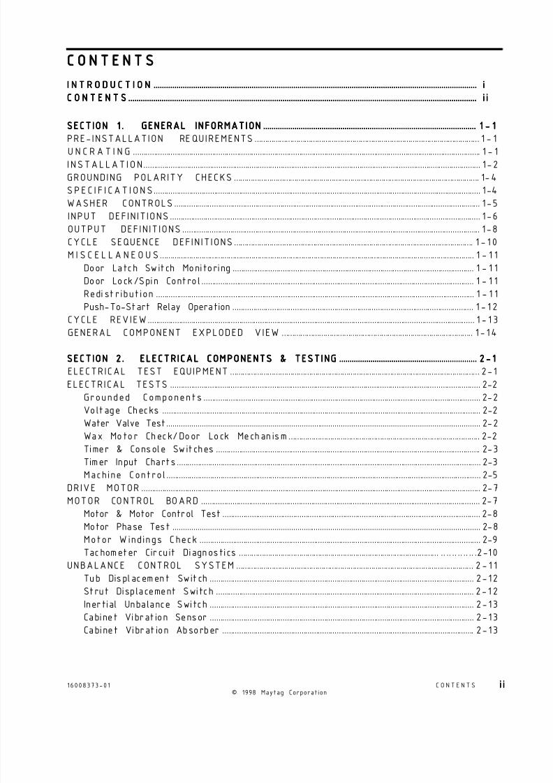
I N T R O D U C T I O NI N T R O D U C T I O NI N T R O D U C T I O NI N T R O D U C T I O NI N T R O D U C T I O N ....................................................................................................................................................................................................................................................................................................................................................................................................................................................................................................................................................................................................................................................................................................................................................................................................... iiiii
C O N T E N T SC O N T E N T SC O N T E N T SC O N T E N T SC O N T E N T S ................................................................................................................................................................................................................................................................................................................................................................................................................................................................................................................................................................................................................................................................................................................................................................................................................................................................... i ii ii ii ii i
SECT ION 1 . GENERAL INFORMATIONSECT ION 1 . GENERAL INFORMATIONSECT ION 1 . GENERAL INFORMATIONSECT ION 1 . GENERAL INFORMATIONSECT ION 1 . GENERAL INFORMATION .............................................................................................................................................................................................................................................................................................................................................................................................................................................................................................................................. 1 - 11 - 11 - 11 - 11 - 1
PRE-INSTALLATION RE QUIREMENTS ............................................................................................................ 1 - 1U N C R A T I N G ....................................................................................................................................................................... 1 - 1
I NSTALLAT I ON.................................................................................................................................................................. 1 -2
GROUNDING POLARITY CHECKS ...................................................................................................................... 1-4
S PE C I F I CAT I ON S ............................................................................................................................................................. 1-4
WASHER CONTROLS ................................................................................................................................................... 1 -5
INPUT DEFIN IT IONS ..................................................................................................................................................... 1 -6
OUTPUT DEF IN IT IONS ............................................................................................................................................... 1 -8
CYCLE SEQUENCE DEFIN IT IONS ................................................................................................................... 1 - 1 0
M I S C E L L A N E O U S ....................................................................................................................................................... 1 - 1 1
Door Latch Switch Monitoring .................................................................................................................... 1 - 1 1
Door Lock/Spin Control ................................................................................................................................... 1 - 1 1
Redi st ribution ......................................................................................................................................................... 1 - 1 1
Push-To-Start Relay Operation .................................................................................................................... 1 - 1 2
CYCLE REVIEW ............................................................................................................................................................. 1 - 1 3
GENERAL COMPONENT EXPLODED VIEW ............................................................................................ 1 - 1 4
SECT ION 2 . ELECTR ICAL COMPONENTS & TEST INGSECT ION 2 . ELECTR ICAL COMPONENTS & TEST INGSECT ION 2 . ELECTR ICAL COMPONENTS & TEST INGSECT ION 2 . ELECTR ICAL COMPONENTS & TEST INGSECT ION 2 . ELECTR ICAL COMPONENTS & TEST ING .......................................................................................................................................................................................................................................................................................................................................... 2 - 12 - 12 - 12 - 12 - 1
ELECTR ICAL TEST EQUIPMENT ........................................................................................................................ 2-1
ELECTRICAL TESTS ..................................................................................................................................................... 2-2
Grounded Components ..................................................................................................................................... 2-2
Voltage Checks ......................................................................................................................................................... 2-2Water Valve Test....................................................................................................................................................... 2-2
Wax Motor Check/Door Lock Mechan ism ............................................................................................ 2-2
Timer & Console Switches ............................................................................................................................... 2-3
Timer Input Charts .................................................................................................................................................. 2-3
Machine Control ....................................................................................................................................................... 2-5
DR IVE MOTOR ................................................................................................................................................................... 2-7
MOTOR CONTROL BOARD ...................................................................................................................................... 2-7
Motor & Motor Control Test ............................................................................................................................ 2-8
Motor Phase Test .................................................................................................................................................... 2-8
Motor W indings Check ....................................................................................................................................... 2-9
Tachometer Cir cuit Diagnostics ................................................................................................ .. .. .. .. .. .. .2-10
UNBALANCE CONTROL SYSTEM .................................................................................................................. 2 - 1 1
Tub Displacement Switch ............................................................................................................................... 2- 12
Strut Displacement Switch ............................................................................................................................ 2- 1 2
Inertial Unbalance Switch ............................................................................................................................... 2- 13
Cabinet Vibration Sensor ............................................................................................................................... 2- 13
Cabinet Vibrat ion Absorber ......................................................................................................................... 2- 13
C O N T E N T SC O N T E N T SC O N T E N T SC O N T E N T SC O N T E N T S
16008373-0 1© 1998 Maytag Corporation
C O N T E N T S i ii ii ii ii i

8/3/2019 Maytag MAH3000AWW Service Manual
http://slidepdf.com/reader/full/maytag-mah3000aww-service-manual 5/157
SECT ION 3 . TROUBLESHOOTINGSECT ION 3 . TROUBLESHOOTINGSECT ION 3 . TROUBLESHOOTINGSECT ION 3 . TROUBLESHOOTINGSECT ION 3 . TROUBLESHOOTING ................................................................................................................................................................................................................................................................................................................................................................................................................................................................................................................................................................................ 3 - 13 - 13 - 13 - 13 - 1
DIAGNOSTIC FLOW CHARTS... . . . . . . . . . . . . . . . .. . . . . . . . . . . . . . . . . . . . . . . . . . . . . . . . . . . . . .. . . . . . . . . . . . . . . . . . . . . . . . . . . . . . . . . . . . . .. . . . .3-4
Fills and Will Not Tumble ................................................................................................................................... 3-4
Washer Overfil ls ....................................................................................................................................................... 3-5
Washer Will Not Spin ........................................................................................................................................... 3-6
Machine Stalls Dur ing Spin ............................................................................................................................... 3-8
Maximum Sp in Speed Is Not Reached ................................................................................................... 3-9
Wash Cycle Takes Longer Than Normal .............................................................................................. 3-10
Suds Coming Out Of Door ............................................................................................................................. 3- 10
Washer Will Not Start ........................................................................................................................................ 3 - 1 1
Motor Phase Test ................................................................................................................................................. 3-12
T IMER TEMPLATE OVERLAY ............................................................................................................................. 3- 13
MISCELLANEOUS INFORMATION .................................................................................................................. 3-1 4
SECT ION 4 . CONSOLESECT ION 4 . CONSOLESECT ION 4 . CONSOLESECT ION 4 . CONSOLESECT ION 4 . CONSOLE ............................................................................................................................................................................................................................................................................................................................................................................................................................................................................................................................................................................................................................................................................................................................ 4-14-14-14-14-1
R E M O V A L ............................................................................................................................................................................. 4- 1
VERTICAL SWITCHES .................................................................................................................................................. 4-2
HORIZONTAL SWITCHES .......................................................................................................................................... 4-2T IMER REMOVAL/REPLACEMENT.................................................................................................................... 4-3
SECT ION 5 . CAB INET ASSEMBLYSECT ION 5 . CAB INET ASSEMBLYSECT ION 5 . CAB INET ASSEMBLYSECT ION 5 . CAB INET ASSEMBLYSECT ION 5 . CAB INET ASSEMBLY ..................................................................................................................................................................................................................................................................................................................................................................................................................................................................................................................................................................................... 5 - 15 - 15 - 15 - 15 - 1
DOOR ASSEMBLY & HINGES ................................................................................................................................. 5-1
Cabinet Vibration Absorber ............................................................................................................................ 5-2
Door Latch Hoop ..................................................................................................................................................... 5-2
FRONT PANEL ................................................................................................................................................................... 5-2
TOP COVER ......................................................................................................................................................................... 5-3
DOOR LOCK MECHANISM ....................................................................................................................................... 5-3
FRONT SHROUD ASSEMBLY ................................................................................................................................. 5-4
CABINE T ASSEMBLY W/REAR AC CE SS PANEL ...................................................................................... 5-5
SECT ION 6 . WATER CARRYING COMPONENTSSECT ION 6 . WATER CARRYING COMPONENTSSECT ION 6 . WATER CARRYING COMPONENTSSECT ION 6 . WATER CARRYING COMPONENTSSECT ION 6 . WATER CARRYING COMPONENTS ................................................................................................................................................................................................................................................................................................................................................................................................................ 6 - 16 - 16 - 16 - 16 - 1
WATER VALVE................................................................................................................................................................... 6-1
WATER LEVEL PRESSURE SWITCH.................................................................................................................. 6-2
AIR DOME HOSE .............................................................................................................................................................. 6-2
D ISPENSER ASSEMBLY ............................................................................................................................................. 6-3
FRONT WATER FLUME INJECTOR ..................................................................................................................... 6-4
PUMP ASSEMBLY .......................................................................................................................................................... 6-4
Pump Accessory ..................................................................................................................................................... 6-5
DRAIN HOSE ....................................................................................................................................................................... 6-6
SECTION 7. OUTER TUB & SPINNER ASSEMBLYSECTION 7. OUTER TUB & SPINNER ASSEMBLYSECTION 7. OUTER TUB & SPINNER ASSEMBLYSECTION 7. OUTER TUB & SPINNER ASSEMBLYSECTION 7. OUTER TUB & SPINNER ASSEMBLY ............................................................................................................................................................................................................................................................................................................................................................................................ 7 - 17 - 17 - 17 - 17 - 1
BAFFLE S ................................................................................................................................................................................ 7-1
DOOR BOOT ........................................................................................................................................................................ 7-1
OUTER TUB COVER ...................................................................................................................................................... 7-2
SPI N BASKET ASS EMBLY W/BALANC E R ING .......................................................................................... 7-3
DRIVE PULLEY .................................................................................................................................................................. 7-4
SPINNER TUB S UPPORT ........................................................................................................................................... 7-5
©1997 Maytag Corporation16008373-0 1 C O N T E N T Si i ii i ii i ii i ii i i

8/3/2019 Maytag MAH3000AWW Service Manual
http://slidepdf.com/reader/full/maytag-mah3000aww-service-manual 6/157
SEAL SYSTEM .................................................................................................................................................................. 7-6
OUTER TUB ASSEMBLY............................................................................................................................................ 7-7
B E A R I N G S ............................................................................................................................................................................ 7-7
COUNTER WEIGHTS .................................................................................................................................................... 7-7
STRUT ASSEMBLY ........................................................................................................................................................ 7-8
Strut Displacement Switch ............................................................................................................................... 7-8
INERTIAL UNBALANCE SWITCH......................................................................................................................... 7-8
TUB DISPLACEMENT SWITCH ............................................................................................................................. 7-9
SECTION 8. MOTOR DRIVE SYSTEMSECTION 8. MOTOR DRIVE SYSTEMSECTION 8. MOTOR DRIVE SYSTEMSECTION 8. MOTOR DRIVE SYSTEMSECTION 8. MOTOR DRIVE SYSTEM ........................................................................................................................................................................................................................................................................................................................................................................................................................................................................................................................................ 8 - 18 - 18 - 18 - 18 - 1
DRIVE BELT ......................................................................................................................................................................... 8- 1
DR IVE MOTOR ................................................................................................................................................................... 8-1
MACHINE CONTROL .................................................................................................................................................... 8-2
MOTOR CONTROL ......................................................................................................................................................... 8-3
SECT ION 9 . ELECTR ICAL SCHEMATICSSECT ION 9 . ELECTR ICAL SCHEMATICSSECT ION 9 . ELECTR ICAL SCHEMATICSSECT ION 9 . ELECTR ICAL SCHEMATICSSECT ION 9 . ELECTR ICAL SCHEMATICS .......................................................................................................................................................................................................................................................................................................................................................................................................................................................................................................... 9 - 19 - 19 - 19 - 19 - 1
Schematic Prior to Series 17 .......................................................................................................................... 9- 1
Timer Chart Prior to Series 17 ....................................................................................................................... 9-2Schemati c Series 17 .............................................................................................................................................. 9-3
Timer Chart Series 17 .......................................................................................................................................... 9-4
Schemati c Series 18 .............................................................................................................................................. 9-5
Timer Chart Series 18 .......................................................................................................................................... 9-6
Schemati c Series 19 .............................................................................................................................................. 9-7
16008373-0 1© 1998 Maytag Corporation
C O N T E N T S i vi vi vi vi v
8/3/2019 Maytag MAH3000AWW Service Manual
http://slidepdf.com/reader/full/maytag-mah3000aww-service-manual 7/157
© 1998 Maytag Corporation
16008373-01 SECTION 1. GENERAL INFORMATION 1-1
SECTION 1. GENERAL INFORMATION
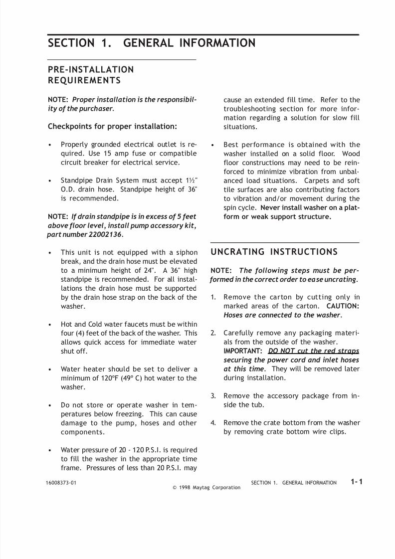
PRE-INSTALLATIONREQUIREMENTS
NOTE: Proper installation is the responsibil-ity of the purchaser.
Checkpoints for proper installation:
• Properly grounded electrical outlet is re-
quired. Use 15 amp fuse or compatible
circuit breaker for electrical service.
• Standpipe Drain System must accept 1½"
O.D. drain hose. Standpipe height of 36"
is recommended.
NOTE: If drain standpipe is in excess of 5 feet
above floor level, install pump accessory kit,
part number 22002136.
• This unit is not equipped with a siphon
break, and the drain hose must be elevated
to a minimum height of 24". A 36" high
standpipe is recommended. For all instal-
lations the drain hose must be supported
by the drain hose strap on the back of the
washer.
• Hot and Cold water faucets must be within
four (4) feet of the back of the washer. This
allows quick access for immediate water
shut off.
• Water heater should be set to deliver a
minimum of 120ºF (49º C) hot water to the
washer.
• Do not store or operate washer in tem-
peratures below freezing. This can cause
damage to the pump, hoses and other
components.
• Water pressure of 20 - 120 P.S.I. is required
to fill the washer in the appropriate time
frame. Pressures of less than 20 P.S.I. may
cause an extended fill time. Refer to thetroubleshooting section for more infor-
mation regarding a solution for slow fill
situations.
• Best performance is obtained with the
washer installed on a solid floor. Wood
floor constructions may need to be rein-
forced to minimize vibration from unbal-
anced load situations. Carpets and soft
tile surfaces are also contributing factors
to vibration and/or movement during the
spin cycle. Never install washer on a plat-
form or weak support structure.
UNCRATING INSTRUCTIONS
NOTE: The following steps must be per-
formed in the correct order to ease uncrating.
1. Remove the carton by cutting only in
marked areas of the carton. CAUTION:
Hoses are connected to the washer.
2. Carefully remove any packaging materi-
als from the outside of the washer.
IMPORTANT: DO NOT cut the red straps
securing the power cord and inlet hoses
at this time. They will be removed later
during installation.
3. Remove the accessory package from in-
side the tub.
4. Remove the crate bottom from the washer
by removing crate bottom wire clips.

8/3/2019 Maytag MAH3000AWW Service Manual
http://slidepdf.com/reader/full/maytag-mah3000aww-service-manual 8/157
© 1998 Maytag Corporation
16008373-01 SECTION 1. GENERAL INFORMATION 1-2
INSTALLATION
1. Two separate red shipping straps are used
to secure the machine for shipping pur-
poses and to secure the power cord with
the water inlet hoses. Remove the straps
in the following sequence:
A. Locate the metal buckles securing the red
straps which extend through slots in the
rear wall of the cabinet. The buckles are
positioned in the center of the red straps.
Carefully cut the red straps, and remove
the metal buckles. NOTE: Cut the straps
as close to the buckles as possible. Dis-
card the buckles.
B. Grasp each loose strap individually and
pull the strap to remove it from the cabi-
net. Discard the strap (Figure 1-2).
2. Tip washer slightly forward. Loosen rear
leveling leg lock nuts. Tip washer back
slightly to loosen front leveling leg lock
nuts (Figure 1-3).
3. Locate the two (2) ½" hex head shipping
bolts extending up through the bottom of
the base (Figure 1-4). The shipping bolts
are near the center of the base toward the
front of the washer. Remove both bolts,
freeing the tub and suspension. Do not
be alarmed should the tub assembly shift
when the last bolt is removed. Some shift-
ing of the tub is normal.
Figure 1-2
Figure 1-3
Figure 1-1

8/3/2019 Maytag MAH3000AWW Service Manual
http://slidepdf.com/reader/full/maytag-mah3000aww-service-manual 9/157
© 1998 Maytag Corporation
16008373-01 SECTION 1. GENERAL INFORMATION 1-3
4. Slide the washer into position and check
the levelness and stability of the washer.
If necessary, slide the washer out of posi-
tion to either raise or lower the leveling
leg as required to level and stabilize the
washer securely on all four legs. Slide the
washer back into position to confirm lev-
elness to the floor. When the washer is
level, tighten the locking nuts up against
the base of the washer. This will secure
the leveling legs in place.
5. Install the rubber feet, found in the instal-
lation package, on all four (4) legs ( Figure1-3).
6. Pull the drain hose vertically to the drain
strap . Then route the drain hose through
the drain hose strap on the back of the
washer and snap into the plastic hook of
the strap.
7. Install gooseneck end of drain hose into
drain standpipe. Be sure the connection
is not airtight between the drain hose andstandpipe. Standpipe must be at least 24"
high. 36" height is recommended.
8. Connect inlet hoses to water supply us-
ing screen washers (found in the installa-
tion package) at faucet connections, with
the domed screen facing the faucet. At-
tach hoses to the faucets and the water
valve.
Figure 1-4
GROUNDING POLARITY CHECKS
The receptacle used for all Maytag products
operating on 120 Volts AC must be properly
grounded and polarized.
The power cord should be equipped with a
three (3) PRONG POLARIZED GROUNDING
PLUG FOR PROTECTION AGAINST SHOCK
HAZARD and should be plugged directly into
a properly grounded and polarized receptacle.
CAUTION: Do not cut or remove the ground-
ing prong from this plug.
It is the responsibility of the person installing
the appliance to ensure it is adequately
grounded and polarized at the point of instal-
lation. Local conditions and requirements
should be taken into consideration. In cases
where only a two (2) prong receptacle is avail-
able, it is the personal responsibility of the
customer to have it replaced with a properly
grounded and polarized three (3) prong recep-
tacle (Figure 1-6).
Figure 1-5
Turn on the water and check for leaks (Figure
1-5). Note the H and C designations on the
water valve bracket for the Hot and Cold
hoses.
NOTE: Accessory inlet hoses are available in
various lengths, up to 10 feet.

8/3/2019 Maytag MAH3000AWW Service Manual
http://slidepdf.com/reader/full/maytag-mah3000aww-service-manual 10/157
© 1998 Maytag Corporation
16008373-01 SECTION 1. GENERAL INFORMATION 1-4
Figure 1-6
SPECIFICATIONS
Plug power cord into a properly grounded 120
volt AC-approved electrical service. This
must be protected by a dedicated 15 amp fuse
or circuit breaker.
All grounding and wiring should be performed
in accordance with national and local codes.
USE OF ADAPTERS IS NOT RECOMMENDED.
CAPACITY 3.1 Cubic Feet
ELECTRICAL 120 volts, 60 Hz; Requir es 15 amp circuit br eaker or f used electrical
supply. Power cord must be connected to a properly grounded and
polarized outlet.
MOTOR Switched Reluctance Motor controlled by a micropro cessor motor
control board. Motor pulley ratio (motor to spinner RPM ) 14 to 1.
POWER USAGE Motor Input: During Wash Tumble - 150 Watts
During Rinse Tum ble - 175 Watt s
Top Spin - 800 Watts
(Wattage readings taken with no clothes in spinner.)
TUMBLER SPEED Wash Tumble 47-51 RPM
Rinse Tum ble 47-51 RPM
Hig h Sp eed Sp in 80 0 RPM (± 50 RPM b ased up on op tim um
spin perfo rmance.)
WATER USAGE Water p ressure should be 20-120 p .s.i. (1.06-8.44 kg/cm ) at inlet hose
connection . Total water usage is app roxima tely 25 gallons; varies w ithclot hes load. Water fill in the spin basket with no clo thes, m easured
near the rear seam of the spin b asket.
WASH LEVEL 3-4 inches
RINSE LEVEL 4-5 inches
HOSE LENGTHS Four-foot inlet h oses with inlet washers and attaches to w ater valve.
Drain hose attaches to pump and w ill accomm odate 36" dr ain stand
pipe.
DIMENSIONS Cabinet dimensions: 27" (68.58cm) W x 27 ½” (69.85cm) D x 36"
(91.44cm)H.
WEIGHT (Approx.) Uncar toned 190lb . (86kg .) Approx .Crated 200lb. (91kg). Approx .
SCREW & BOLT TORQUES Bolt, Counter Weight 7in. lbs. (± 3in.lbs)
Bolt, Spin Pulley 30in. lbs (± 3in. lbs)
Bolt, Belt Adjuster 90in. lbs (± 10in. lbs)
Screw , Front Baffle 25in. lbs (± 3in. lbs)
Screw , Rear Baffle 18.5in. lbs (± 3in. lbs)
Clamp, Hoses 15+ in. lbsNuts, Spinner Support 18in. lbs (± 3in. lbs)
Nuts, Suspension Struts 7in. lbs (± 3in. lbs)

8/3/2019 Maytag MAH3000AWW Service Manual
http://slidepdf.com/reader/full/maytag-mah3000aww-service-manual 11/157
© 1998 Maytag Corporation
16008373-01 SECTION 1. GENERAL INFORMATION 1-5
WASHER CONTROLS
The control system in the Neptune horizontal axis washer generally consists of a timer and
microprocessor-based machine control. These receive input signals and send output signals to
other equipment in the washer, including the motor and motor control, user input switches,
user indicator lights, the door latch and lock assembly, water valves, drain pump, unbalance
switches, dispenser actuator wax motors, a pressure switch, and a tub light.
The machine control has direct control of these items:
- Motor speed and direction, through signals to the motor control.
- Door lock wax motor.
- Hot and cold water valves, with an input signal from the timer and pressure switch.
- Timer motor.
- On Light.
In general, the timer dial is rotated to a desired setting, selects the cycles options using the
option switches, and starts the washer. The machine control reads the inputs from the timer,option switches and pressure switch then send output signals to the motor control and other
components based upon those inputs. When the machine control has completed its set of
instructions for the specific timer setting, it energizes the timer motor output to advance the
timer to the next increment, reads a new set of input signals from the timer, and acts upon
them. This continues until the cycle is complete. (See Figure 1-7 & 1-8 for a generic representa-
tion of the Neptune washer control system.)
Figure 1-7
Prior To Series 17

8/3/2019 Maytag MAH3000AWW Service Manual
http://slidepdf.com/reader/full/maytag-mah3000aww-service-manual 12/157
© 1998 Maytag Corporation
16008373-01 SECTION 1. GENERAL INFORMATION 1-6
INPUT DEFINITIONS
DOOR LOCK SWITCH INPUT
When input is present, this is indication the
washer door is locked. The machine control-
ler will not command the spinner to spin faster
than 50 rpm when the input is not present
prior to spin.
END-OF-CYCLE SIGNAL INPUT
The End-of-Cycle Signal Input is energized
through a user input switch on the control
panel. When this is energized and the cycle
has finished, the machine control will sound
the End-of-Cycle signal (See End-Of-Cycle Sig-
nal Output).
FABRIC SELECTION INPUTS
The Fabric Selection Inputs are energized
through a user input switch on the control
panel. The machine control reads these in-
puts to determine which cycles should be runwhen the washer is started.
MAX EXTRACT INPUT
The Max Extract Input is energized through a
user input switch on the control panel. When
input is energized, the machine control will
modify the final spin profile to the max ex-
tract profile.
NOTE: If the user selects the Hand Washables
fabric selection, all spins will follow the Max
Extract profile regardless of whether the user
selects the Max Extract option.
OUT-OF-BALANCE INPUT
The Out-of-Balance Input Signal is provided
by three normally-closed switches wired in
sequence. If any of these switches opens due
to an out-of-balance condition, the signal will
be momentarily lost (See Unbalance Control
System).
PRESSURE SWITCH INPUT
The input signal from the Pressure Switch
serves two purposes. It supplies power for
the water valves and provides an indication
to the machine control as to whether the com-
manded water level has been reached.
When the timer advances into a cycle se-
quence that calls for water, power is supplied
through the timer to either the wash or rinselevel contacts on the pressure switch. When
the water level in the tub is below the full level
for that setting, the pressure switch circuit is
closed, supplying power for the water valves
to the machine control. When the water level
switch is satisfied, the pressure switch circuit
is opened and power for the water valves is
no longer passed to the machine control. The
Figure 1-8
Series 17 & Later

8/3/2019 Maytag MAH3000AWW Service Manual
http://slidepdf.com/reader/full/maytag-mah3000aww-service-manual 13/157
© 1998 Maytag Corporation
16008373-01 SECTION 1. GENERAL INFORMATION 1-7
When the washer is at the "full" level and the
timer is set in a Prewash Tumble, Main Wash
Tumble, Light Wash Tumble, or Rinse Tumble
increment, the machine control will begin the
sequence timing defined for each cycle and
fabric selection setting (See Cycle Sequence
Definitions).
During the drain and spin increments after the
main wash, first rinse, second rinse, and ex-
tra rinse increments, the wash side circuit in
the pressure switch is closed. When the wa-
ter level drains below the wash full level, the
circuit will close and energize the pressure
switch input. The machine control interprets
this signal (not to energize the water valve
outputs) to measure how quickly the washer
is draining. If the machine control commands
a spin speed above 51 rpm before the pres-
sure switch input is energized, it will drop the
speed to 0 rpm and hold there until the pres-
sure switch input is energized. An additional
delay equal to the length of time elapsed will
occur before the pressure switch input is en-
ergized. If four minutes elapse without the
pressure switch input being energized, the
machine control will energize the timer mo-
tor output to advance the timer into the next
increment and continue with the cycle.
START/STOP INPUT
The start/stop input is energized by the mo-
mentary Push-to-Start/Stop Switch. If this in-
put is energized when a cycle is in progress,
the machine control will disengage the line
relay, both water valve output signals, the door
lock wax motor signal, the timer motor out-
put signal, and the on-light output signal. If
this input is energized when a cycle is not in
progress, the machine control will energize
the line relay and begin the cycle sequence as
defined by the timer and user input switches
(See Push-To-Start/Line Relay Operation).
TACH INPUT
The tach input is a feedback signal from the
motor control. It provides eight pulses per
revolution of the switched reluctance motor.
The motor runs at 14 times the speed of the
spinner (14:1 belt ratio). The tach input is used
for monitoring speed and out-of-balance de-
tection (See Tachometer Circuit Diagnostics).
If the machine control commands a motor
speed and direction but does not sense a tach
input signal within five seconds, it will disen-
gage the line relay to stop the washer. This
generally indicates a locked rotor or a mal-
function in the motor control.
If the machine control senses a tach input sig-
nal when it is not commanding the motor torun, it will disengage the line relay to stop the
washer.
If the machine control commands a coast
down from final spin speed but is still receiv-
ing a tach input signal after two minutes, it
will disengage the line relay to stop the washer.
TEMPERATURE SENSOR INPUT
A thermistor is located in the water valve to
monitor the blended incoming water tempera-ture. The machine control uses this input sig-
nal to regulate the water temperature with the
warm or cold wash or warm rinse tempera-
ture selections (See Water Valve Outputs).
TIMER INPUTS
The Timer Input signals are energized through
the cams in the timer. The timer operates with
a 30 second drive cycle and a 5.8 second ad-
vance time (See Timer Input Charts).
WATER TEMPERATURE INPUTS
The Water Temperature inputs are two sepa-
rate signals defined by a user input switch on
the control panel. The machine control inter-
prets these signals to determine what the wa-
ter temperature should be for each fill (See
Water Valve Outputs).
machine control interprets this loss of power
as an indication that the water level has
reached the full level.

8/3/2019 Maytag MAH3000AWW Service Manual
http://slidepdf.com/reader/full/maytag-mah3000aww-service-manual 14/157
© 1998 Maytag Corporation
16008373-01 SECTION 1. GENERAL INFORMATION 1-8
OUTPUT DEFINITIONS
DOOR LOCKED LIGHT OUTPUT
NOTE: This section applies only to washers
between Series 10 and 16. The "Door Locked"
lights on washers from Series 17 and after are
controlled by a "Door Locked" light switch.
The Door Locked Light Output signal powers
a 1/3 watt neon indicator lamp on the control
panel. This output is first energized when the
Door Lock Wax Motor Output is energized. At
the end of the cycle, it remains energized for
50 seconds after the Door Lock Switch Input
shuts down. This delay allows the wax motor
to fully retract and unlock the door.
NOTE: The washer will continue to tumble
at the end of cycle until this 50 second delay
is elapsed.
DOOR LOCK WAX MOTOR OUTPUT
The Door Lock Wax Motor Output signal pow-
ers a wax motor in the door lock assembly.
The wax motor extends to drive the door lock
system for the washer.
If the washer is started with the timer set in a
Prewash Tumble, Main Wash Tumble, or Light
Wash Tumble increment, the machine control
will wait for three minutes before energizing
the Door Lock Wax Motor Output. This delay
is not affected by water level. This output re-
mains energized until the end of the cycle.
If the washer is started with the timer set in a
Prewash Drain, Bleach Dispense, Spin1, Rinse
Tumble, Spin2, or Spin3 increment, the ma-chine control will energize this output imme-
diately.
The machine control will continuously ener-
gize the Door Lock Wax Motor Output during
the final (Spin 3) sequence until 30 seconds
before the washer begins to coast from the
final speed.
END-OF-CYCLE SIGNAL OUTPUT
The End-Of-Cycle Signal Output is an inter-
nal signal on the machine control between the
microprocessor and annunciator. The end-of-
cycle signal sounds when a wash cycle is fin-
ished and the End-Of-Cycle Input is energized.
The end-of-cycle signal sounds as six pulses
in a 0.35 seconds on, 0.15 seconds off pattern
(See Timer Input Charts).
ON LIGHT OUTPUT
NOTE: This section applies only to washers
from Series 17 and after. The "Door Locked"
lights on washers between Series 10 and 16
are controlled by a cam on the timer.
The Door Locked Light Output signal powers
a 1/3 watt neon indicator lamp on the control
panel. This output is energized when the
washer is operating in a wash or spin cycle.
Note that the "On" light is not illuminated when
the timer is in a delay increment.
TIMER MOTOR OUTPUT
The machine control energizes the Timer
Motor Output to allow for variable-length
timer increments. If the washer is started with
the timer set in a Prewash Tumble, Main Wash
Tumble, Light Wash Tumble, or Rinse Tumble
increment, the machine control will not be-
gin the cycle sequence timing until the water
level reaches the appropriate level. The Timer
Motor Output is disengaged during this time.
The machine control will stop the washer by
disengaging the line relay if the following oc-
cur: 1) The machine control energizes the
timer motor until it senses a timer change. 2)
The timer motor remains energized for fiveminutes while the timer inputs change (See
Timer Input Charts).

8/3/2019 Maytag MAH3000AWW Service Manual
http://slidepdf.com/reader/full/maytag-mah3000aww-service-manual 15/157

8/3/2019 Maytag MAH3000AWW Service Manual
http://slidepdf.com/reader/full/maytag-mah3000aww-service-manual 16/157
© 1998 Maytag Corporation
16008373-01 SECTION 1. GENERAL INFORMATION 1-10
CYCLE SEQUENCE DEFINITIONS
NOTE: Refer to Section 2: Timer Input Charts
for information on the timing of each cycle
sequence.
BLEACH DISPENSE
In a Bleach Dispense increment, the machine
control will follow the same tumble pattern
and speed as in a Main Wash Tumble incre-
ment.
DELAY
During a Delay increment, the door Lock Wax
Motor Output, Door Locked Light Output (Se-
ries 17 and later only), Motor Torque Output,
"On" light (Series 10 to 16 only), and Water
Valve Outputs are de-energized. Note that the
Delay indicator is energized through a cam
on the timer.
EXTRA RINSE
When the user selects the Extra Rinse option,
the spin increment following the third rinse
will follow the Spin2 cycle sequence. The
Timer Motor Output will be energized 60 sec-
onds prior to the end of the spin cycle se-
quence and will remain energized to advance
the timer through the "Off" increment into the
Rinse Tumble increment.
If the Extra Rinse option is not selected, this
spin will follow the Spin3 cycle sequence and
the Timer Motor Output will be energized 30
seconds prior to the end of the final spin.
IDLE
The Idle increment follows the final spin in-
crement in each cycle. If the Door Lock Switch
Input is energized when the timer advances
into the Idle increment at the end of the cycle,
the machine control will tumble the washer
until 50 seconds after the Door Lock Switch
input is no longer energized. This allows time
for the Door Lock Wax Motor to fully retract.
At this time, the Door Lock Light Output
(washers between Series 10 and 16 only) or
the "On" Light Output (Series 17 and later
washers only) will de-energize and the End-
of-Cycle Signal will sound if the user had se-
lected the End-of-Cycle Signal option.
LIGHT WASH TUMBLE, MAIN WASH
TUMBLE, and RINSE TUMBLE
The machine control will tumble the washer
at the pattern and speed defined by the Fabric
Selection Inputs (See Cycle Review). Each
tumble will start only after the previous
tumble has completely stopped. The machine
control will reverse the tumble direction after
each pause. The machine control will con-
tinue to tumble the washer until the timer in-
puts change.
In a Light Wash Tumble or Main Wash Tumble
increment, the machine control will de-ener-
gize the line relay if the washer continues to
tumble for 29 minutes. This would only oc-
cur if the timer were to stall (See Section 1:
Timer Motor Output and Section 2: Timer
Input Chart).
PREWASH DRAIN
During a prewash drain increment, the washer
will tumble at the same speed and in the same
pattern as in the Prewash Tumble increment
for the fabric selection. The Door Lock Wax
Motor Output will be energized during this
increment (See Prewash Tumble).
PREWASH TUMBLE
When the timer is set into a Prewash Tumble
increment, the machine control will tumble
at 51 rpm in the following tumble pattern:
Cycle Tumble-Pause Pattern
Cotton/Sturdy 6 sec. - 24 sec.
Easy Care/Perm Press 6 sec. - 24 sec.Delicates 6 sec. - 24 sec.
Hand Washables 3 sec. - 27 sec.

8/3/2019 Maytag MAH3000AWW Service Manual
http://slidepdf.com/reader/full/maytag-mah3000aww-service-manual 17/157
© 1998 Maytag Corporation
16008373-01 SECTION 1. GENERAL INFORMATION 1-11
MISCELLANEOUS
Door Latch Switch Monitoring
At the end of a cycle, when the timer advances
into the Idle increment, the machine control
will keep the line relay energized until it loses
power when the door latch switch opens. This
guards against the switch contacts weldingclosed. In this condition, the machine con-
trol will limit what additional cycles can be run
before the door is opened as follows:
Washers between Series 10 and 16
The machine control will allow the washer
to restart only if the user sets the timer
into a Rinse Tumble or Spin3 increment.
Washers from Series 17 and Later
The machine control will allow the washerto restart in any setting. After that cycle
completes, the user must open the door
before the machine control will allow a
third cycle to start.
Door Lock/Spin Control
When the machine control begins a spin in-
crement, it will not command spin speed
above 51 rpm unless the door lock switch in-
put is energized. At the start of a spin incre-
ment, the machine control will drop the speed
to 0 rpm then tumble until the switch is ener-
gized. At that point, it will restart the spin se-
quence. If the door lock switch is not ener-
gized after 2 minutes of tumbling, the machine
control will energize the timer motor output
until the timer inputs change so the washer
can proceed with the cycle.
At the end of spin sequence, if the door lock
switch input is de-energized before the washer
drops below 91 rpm, a hardware circuit on the
machine control will interrupt the torque out-
put signal, which forces the motor control to
0 rpm, and energize the door lock wax motor
circuit to lock the door. This hardware circuit
will keep the door lock wax motor circuit en-
ergized until the door lock switch input signal
is energized.
Redistribution
The machine control commands a distribu-
tion profile speed ramp from 0 rpm to 85 rpm
at the beginning of each high speed (above
100 rpm) spin. When the washer reaches 85
rpm, the machine control monitors the Tach
Input to determine if the speed varies through
one revolution of the spinner basket. If it
senses a high enough variation in speed (sug-
gesting an out-of-balance condition in the
clothing load), it will drop the spinner speed
to 0 rpm and force a short reverse tumble to
redistribute the clothing load before resum-
ing the spin. If any of the out-of-balance
switches trip and open the out-of-balance in-
put circuit at a speed below 500 rpm, the ma-
chine control will also drop the speed to 0 rpm
and force the reverse tumble to redistribute
the clothing load.
In a Prewash Tumble increment, the machine
control will de-energize the line relay if the
washer continues to tumble for 15 minutes.
This would only occur if the timer were to stall
(See Section 1: Timer Motor Output and Sec-
tion 2: Timer Input Chart).

8/3/2019 Maytag MAH3000AWW Service Manual
http://slidepdf.com/reader/full/maytag-mah3000aww-service-manual 18/157
© 1998 Maytag Corporation
16008373-01 SECTION 1. GENERAL INFORMATION 1-12
The following rules determine the maximum
number of redistribution attempts that will be
allowed in each spin step before the machine
control skips the step and continues with the
spin profile (See Section 2: Unbalance Con-
trol System).
STOPPING THE WASHER
1. With the washer running, power is
supplied to the machine control and
washer from gray wire no. 26 through the
line relay.
2. When the user presses the push-to-start
button, a signal is sent to the machine con-
trol through red wire no. 28 telling the
washer to shut down.
3. The machine control opens the internal
logic switch which de-energizes the line
relay.
4. When the user releases the push-to-start
button, power is removed from the ma-
chine control and washer (Black wire no.
27).
STARTING THE WASHER
1. With the door closed, press the push-to
start switch.
2. The red no. 28 wire sends a signal to the
machine control to start running.
3. 120 VAC is supplied to the machine con-
trol board through black wire no. 27.4. The machine control closes an internal
switch to energize the line relay.
5. When the push-to-start button is released,
power remains supplied to the machine
control and the washer from gray wire
no. 26 through the line relay.
Push-To-Start Relay Operation
PUSH TO START SWITCH
LINERELAY
MACHINE CONTROL BOARD
120 VAC POWERFROM MACHINECONTROL BOARD
INTERNAL LOGICSWITCH
120 VAC LINE(When door is
closed)
GY 26 BK 27
RD 28
120 VAC LineTo Timer &Motor Control Board
NO COM
Figure 1-8

8/3/2019 Maytag MAH3000AWW Service Manual
http://slidepdf.com/reader/full/maytag-mah3000aww-service-manual 19/157
© 1998 Maytag Corporation
16008373-01 SECTION 1. GENERAL INFORMATION 1-13
CYCLE REVIEW
Main Wash Time/Total Cycle Time - Minutes (See Notes).
Notes:
1. The main wash times listed include 2 minutes of bleach fill and tumble time.
2. The total cycle times are approximate and will vary based on water fill times, due to types of
clothing loads, available water pressure and the time for the door lock system to retract at
the end of the cycle.
3. The main wash time is affected significantly if the machine control detects an excessive
amount of suds. The washer will go into a suds reduction routine, consisting of a series of
additional rinse and partial drain cycles to reduce the suds present (See Troubleshooting &
Diagnosis - Clothes Wet at End of Spin).
Tumble Pattern - Number of seconds tumbling/Number of seconds of pause between tumbles.
N o n- M ax
Ex t ra ct C o t t o n / S t u rd y
Ea sy C a r e /
Pe rm Press D e licat e s
H a n d
W a sh a b l es
H e av y W ash 23 .0 /4 9.0 20 .0 /4 5.5 20 / 46. 5 N o t A p p l ic ab le
N o r m al W ash 17 .0 /4 3.0 14 .0 /3 9.5 14 .0 /4 0.5 N o t A p p l ic ab le
L i g h t / Q u i c k
W a s h
11 .0 /3 7.0 8.0 / 33 .5 7.0/ 34 .5 N o t A p p l ic ab le
F in a l Sp i n
(R PM / M i n )
80 0 /3. 5 60 0 / 3. 0 50 0 /4. 5 N o t A p p l ic ab le
M a x E x t ra ct
C ycle s C o t t o n / S t u rd y
Ea sy C a r e /
Pe rm Press D e licat e s
H a n d
W a sh a b l es
H e av y W ash 23 .0 /4 6.0 20 .0 /4 1.5 20 .0 /4 2. 0 20 .0 /4 3. 0
N o r m al W ash 17 .0 /4 0.0 14 .0 /3 5.5 14 .0 /3 6. 0 14 .0 /3 7. 0
L i g h t / Q u i c k
W a s h
11 .0 /3 4.0 8.0 / 29 .5 8 .0 /3 0.0 8 .0 /3 1.0
F in a l Sp i n
(R PM / M i n )
80 0 /4. 0 60 0 / 3. 5 50 0/ 5.0 50 0/5. 0
Cotton/ Sturdy Easy Care/
Perm Press
Delicates Hand Washables
7/3 5/3 6/24 3/27

8/3/2019 Maytag MAH3000AWW Service Manual
http://slidepdf.com/reader/full/maytag-mah3000aww-service-manual 20/157
© 1998 Maytag Corporation
16008373-01 SECTION 1. GENERAL INFORMATION 1-14
GENERAL COMPONENT EXPLODED VIEW

8/3/2019 Maytag MAH3000AWW Service Manual
http://slidepdf.com/reader/full/maytag-mah3000aww-service-manual 21/157
© 1998 Maytag Corporation
2 - 12 - 12 - 12 - 12 - 11 600 8373-0 1 SECTION 2. ELECTRICAL COMPONENTS & TESTING
SECTION 2 . ELECTRICAL COMPONENTS & TESTINGSECTION 2 . ELECTRICAL COMPONENTS & TESTINGSECTION 2 . ELECTRICAL COMPONENTS & TESTINGSECTION 2 . ELECTRICAL COMPONENTS & TESTINGSECTION 2 . ELECTRICAL COMPONENTS & TESTING
Descr ipt i onDescr ipt i onDescr ipt i onDescr ipt i onDescr ipt i on Part NumberPart NumberPart NumberPart NumberPart Number
Analog Test Meter 20000005
Digital Test Meter 2 0 00 1 0 0 1
Clamp-On Ammeter 20000002
AC Voltage Sensor 2000008 1
Digital Test MeterDigital Test MeterDigital Test MeterDigital Test MeterDigital Test Meter
can be used to check for
open or closed circuits,
measure resistance,AC and DC volts,
and temperature.
AC Voltage SensorAC Voltage SensorAC Voltage SensorAC Voltage SensorAC Voltage Sensor
can be used to alert you if
AC voltage is present so proper
safety precautions can be observed.The tip of the sensor will glow
bright red if voltage is between
110-600 volts AC.
C lamp-On AmmeterClamp-On AmmeterClamp-On AmmeterClamp-On AmmeterClamp-On Ammeter
can be used to detect
shorts. Overloads on
the circuit
breaker or fuse
can be traced
to either the
washer or circuit
breaker by check-
ing the washer
current draw.
Analog Test MeterAnalog Test MeterAnalog Test MeterAnalog Test MeterAnalog Test Meter
can be used to check
for open or closed
circuits, measure resis-
tance, AC and DC volts,
and temperature.
The equipment required to service Maytag
products depends largely upon the conditions
you encounter. Locating a malfunction will
ELECTRICAL TEST EQUIPMENTELECTRICAL TEST EQUIPMENTELECTRICAL TEST EQUIPMENTELECTRICAL TEST EQUIPMENTELECTRICAL TEST EQUIPMENT
often require the use of electrical testing
equipment such as:

8/3/2019 Maytag MAH3000AWW Service Manual
http://slidepdf.com/reader/full/maytag-mah3000aww-service-manual 22/157
© 1 9 9 8 M a y t a g C o r p o r a t i o n
16 0 0 8 3 7 3 - 0 1 SECTION 2. ELECT RICA L COMPONENTS & TEST ING 2 - 2
ELECTRICAL TESTS
Warn ing - A l w a y s s h u t o f fe l e c t r i c a l p o w e r t o t h eu n it b e f o r e b e g in n in g a n y
s e r v i c e r e p a i r p r o c e d u r e s .
W a t e r V a l v e T e s t
C h e c k t h e w a t e r v a l v e f o r e l e c t r i c a l c o n t i n u -
i t y . Th is check shou ld be made wit h t he e lec -
t r i c a l s u p p l y d i s c o n n e c t e d f r o m t h e w a s h e r .
Re m o v e t h e w i r e h a r n e s s f r o m t h e wa t e r v a l v e
t e r m in a l s a n d p l a ce t h e o h m me t e r p r o b e s o nt h e t e r m in a l s o f t h e w a t e r v al v e . T h e w a t e r
v a l v e s o l e n o i d c o i l s h o u l d h a v e a r e s i s t a n c e
b e t w e e n 5 0 0 - 10 0 0 o h ms . I f n o o h ms a r e
s h o w n o n t h e d i s p l a y o f t h e e l e c t r i c a l t e s t
me t e r , t h e s o l e n o i d c oi l h a s a n o p e n w i nd i n g
a n d t h e v a l v e s h o ul d b e r e p l a c e d. T h e t h e r -
m is to r i n the wa te r va l ve changes in res i s tance
i n d i r e c t r e l a t i o n s h i p t o w a t e r t e m p e r a t u r e s .
T o m o n i t o r t h e p e r f o r m a n c e o f t h e t h e r m i s t o r ,
r u n a p a r t i a l h o t wa t e r f i l l a n d c h e c k t h e o h m
r e s i s t a n ce o f t h e t h e r mi s t o r c ir c ui t . T h e n, r u na c o l d w a t e r f i l l a n d m e a s u r e t h e r e s i s t a n c e
a g a in . T h e r e s h o u l d b e a n o t a b l e d i f f e r e n c e
i n t h e r e s i s t a n ce r e a d in g s . T o c h ec k t h e o h m
r e s i s t a n c e , p u l l t h e P 2 w i r e h a r n e s s c o n n e c -
t o r o f f t h e m a c h i n e c o n t r o l a n d l o c a t e t h e
P2 ( 5) a n d P2 (6 ) l e a d s i n t h e c o n n e ct o r
( Fi g u r e 2 - 3 ).
V o l t a g e C h e c k s
G e n e r a l l y , t h e s e c h e c k s w i l l c o n s i s t o f t a k i n g
r e a d i n g s a t t h e w a l l r e c e p t a c l e t o d e t e r m i n e
t h e a v ai l ab il i t y o f v o l t a g e t o t h e p r o d uc t . Vo l t -
a g e c h e ck s o n i n d i v i d u a l c o mp o n e n t s o f a
p r o d u c t a r e n o t r e c o m m e n d e d d u e t o t h e
p o s s i b il i t y of e l e c t r i ca l s h o ck . Co mp o n en t p a r t
t e s t i n g i s b e s t a c c o m p l i s h e d t h r o u g h c o n t i -
n u i t y c h e c k s w i t h a n A p p l i a n c e T e s t M e t e r( S e e El e c t r i c al T e s t Eq u i p me n t ) .
NOTE: U s e o f t h e m e t e r o n v o l t a g e h i g h e r
t h a n t h e i nd i ca t e d r a n g e ma y c a u s e p e r ma -
nen t damage t o t he me t e r . To p r ev en t dam-
a g e , f i r s t s e l e c t t h e h i g h e s t r a n g e a n d t h e n
l ow e r the r ange fo r r ead ings w h i c h fa l l w i th i n
t h e l o w e r s c a l e .
S e t u p m e t e r f o r u s e a s f o l l o w s :
1. T u r n s e l e ct o r k n o b t o d e s ir e d me t e r f u n c-t i o n a n d a p p r o p r i a t e r a n g e .
2 . P lug b lack lead in t o socke t marked black( - ) .
3 . P lug r ed lead in t o socke t mark ed r ed (+).
4 . P l a ce t e s t l e a ds in t o r e c e pt a cl e t o d e t e r -mi n e v o l t a g e a v a i l a b l e .
W a x Mo t o r Ch e ck - Do o r L o ckM e c h a n i s m
C h e c k t h e w a x m o t o r f o r p r o p e r r e s i s t a n c e .
T h i s c h ec k s h o u l d b e ma d e w i t h t h e e l e c t r i ca l
s u p p l y d i s c o n n e c t e d f r o m t h e w a s h e r . Re -
m o v e t h e w i r e h a r n e s s f r o m t h e w a x m o t o r
t e r m in a l s a n d p l a ce t h e o h m me t e r p r o b e s o n
t he t e rm ina ls o f t he wax mot o r . The wax mo-
t o r s h o u l d h a v e a r e s i s t a n c e o f a p p r o x i m a t e l y
19 0 0 o h ms a t r o o m t e mp e r a t u r e . T o c h ec kw a x m o t o r s t h r o u g h c o n s o l e , s e e s e c t i o n :
Ma c hi n e Co n t r o l p a g e 2 - 5 .
Gr o u n d e d Co m p o n e n t s
W h e n pe r f o r m i n g s e r v i c e d i a gn o s t i cs , r e -
p l a c eme n t s a n d r e p a ir s , a l w a y s c h e ck t o d e -
t e r m i n e w h e t h e r a l l g r o u n d w i r e s l i n k i n g
p a n e l a nd c omp o n e nt s a r e r e a t t a c he d if
r e m o v e d .

8/3/2019 Maytag MAH3000AWW Service Manual
http://slidepdf.com/reader/full/maytag-mah3000aww-service-manual 23/157
© 1998 Maytag Corporation
2-32-32-32-32-316008373-01 SECTION 2. ELECTRICAL COMPONENTS & TESTING
Timer & Console SwitchesTimer & Console SwitchesTimer & Console SwitchesTimer & Console SwitchesTimer & Console Switches
The timer is located in the control console on
the back. It is composed of a series of switches
driven by an electric timer motor. The timer
motor rotates a pinion gear which then rotates
internal cams. As the cams rotate, they liftand drop various switch contacts which ride
on the cam. The internal switches provide
cycle sequence or step inputs to the machine
control to control the pump, dispenser wax
motors, delay light, ON light and timer motor.
The timer wire harness connector can be
pulled and the individual contacts for the vari-
ous circuits can be checked with an ohm
meter. As illustrated, timer contact for the
drain pump is 14T (Figure 2-1).(Figure 2-1).(Figure 2-1).(Figure 2-1).(Figure 2-1) .
You can identify the wire for the drain circuit
(Figure 2-2) (Figure 2-2) (Figure 2-2) (Figure 2-2) (Figure 2-2) by tracing down the side of the
connector to contact 14, and across to align
with column T.
Contact 8B in the connector is a direct con-
tact to the neutral leg of the timer. When an
ohm meter probe is placed into the 14T con-nection and the other probe is placed into 8B,
an ohm reading of the complete drain circuit
can be performed. The drain circuit should
have a resistance of approximately 18 ohms.
This is the resistance reading of the pump
Figure 2-1 Figure 2-1 Figure 2-1 Figure 2-1 Figure 2-1
Figure 2-2 Figure 2-2 Figure 2-2 Figure 2-2 Figure 2-2
Description Connector Connector Ohms
Pump
Motor 14T 10B 18
Bleach Wax
Motor 2B 10B 950-1100
Softener
Wax Motor
2T 10B 950-1100
Timer
Motor 10T 10B 5000
Timer Input ChartsTimer Input ChartsTimer Input ChartsTimer Input ChartsTimer Input Charts
As stated previously, the machine control
board receives inputs from the timer monitor
where the timer is in the cycle. The machine
control board accomplishes this by routing
four circuits through the timer. Two of the cir-
cuits (1A & 1B) are supplied with 120 VAC and
the other two circuits (2A & 2B) are 24 VDC.
The voltages for the four circuits is shown on
the timer chart of the electrical schematic
enclosed in the washer console.
motor windings. The following chart can be
used for checking other components via the
timer wire harness connector.
TTTTT CCCCC BBBBB

8/3/2019 Maytag MAH3000AWW Service Manual
http://slidepdf.com/reader/full/maytag-mah3000aww-service-manual 24/157
© 1 9 9 8 M a y t a g C o r p o r a t i o n
16 0 0 8 3 7 3 - 0 1 SECTION 2. ELECT RICA L COMPONENTS & TEST ING 2 - 4
Ke y: 0 = In pu t Sign al Not A s s er t e d 1= In pu t Sig na l A s s e r t e d
S o f t w a r e i n t h e m a c h i n e c o n t r o l b o a r d s p e c i f i c a l l y m o n i t o r s t h e t i m e r i n p u t c i r c u i t s t o
d e t e r m in e wh er e t h e t i me r i s i n a l l t h e wa s h cy c l e s a n d w il l r a p id l y a d v a n ce t h e t i me r t o
OPEN a n d b r e a k c on t a c t s i n t h e t i me r . T h e t i me r i s s o l e l y u s e d a s a n o f f - b o a r d s e t o f
r e l a y s w i t c h e s . N o t e : The t ime r mo t o r i s ha r d w i r ed t o t ime r c ams 10T and 10B in t he
t i m e r .
CYCLE SEQUENCE
TIMER 1A(120 VAC)
PK19/P7(8)
TIMER 1B(120 VAC)
YL16/P7(7)
TIMER 2A(24 VDC)
PU17/P3(3)
TIMER 2B(24 VDC)
BU18/P3(5)
PREWASH TUMBLE 0 1 1 0
PREWASH DRAIN 1 1 1 0
MAIN WASH TUMBLE 0 1 0 0
LIGHT WASH TUMBLE 1 1 0 0
BLEACH DISPENSE 1 0 1 0
RINSE TUMBLE 1 0 0 1
SPIN 1 0 0 1 0
SPIN 2 0 0 0 1
SPIN 3 0 1 0 1
EXTRA RINSE 1 1 0 1
DELAY 1 0 0 0
IDLE 0 0 0 0
T h e r e a r e c o n d i t i o n s u n d e r w h i c h t h e m a c h i n e c o n t r o l w i l l s h u t t h e c y c l e d o w n i f t h e
t i m e r d o e s n o t a d v a n c e .
- Du r i ng Ex t r a Wa s h/ P r e w as h : If t h e t i me r in pu t s d o n ot c ha ng e a w ay f r o m P r e w as h
T u mb l e f o r 15 mi n ut e s , t h e ma c hi n e co n t r o l w i l l o p e n t h e l i n e r e l a y .
- Du r i n g Ma in Wa s h : If t h e t i me r i np u t s d o n o t c ha ng e f o r 2 9 mi nu t e s , t h e ma ch in e
c o n t r o l w i l l o p e n t h e l i n e r e l a y .
- Du r i n g a n y in cr e me nt w h en t h e ma ch in e co nt r o l e n er g i z e s t h e t i me r mo t o r u nt i l it
sees t he t imer i npu t s change: If t he t imer i npu t s do no t change f o r 5 minut es w it h the
t i m e r m o t o r c o n t i n u o u s l y e n e r g i z e d , t h e m a c h i n e c o n t r o l w i l l o p e n t h e l i n e r e l a y .
T h e s e v a r y i n g d e l a y s a r e t o a l l o w t h e w a s h e r t o p r o g r e s s t h r o u g h s e v e r a l i n c r e m e n t s
w h e r e t h e t i me r i n p u t s n o r ma l l y d o n o t c h a n g e. In t h e s e c a s e s , t h e ma c h in e c o nt r o l
energ i zes t he t imer mot o r f o r 30 seconds , wh ich i s i t s advance t ime . It does no t l ook f o r
a t i m e r i n p u t c h a n g e .

8/3/2019 Maytag MAH3000AWW Service Manual
http://slidepdf.com/reader/full/maytag-mah3000aww-service-manual 25/157
© 1998 Maytag Corporation
2-52-52-52-52-516008373-01 SECTION 2. ELECTRICAL COMPONENTS & TESTING
Figure 2-3 Figure 2-3 Figure 2-3 Figure 2-3 Figure 2-3
Both incoming and exiting voltage are monitored through the machine control board and thesurrounding circuitry. The following table lists the voltages for the various terminals on the
microprocessor board. If proper voltage is not present, check switches and wiring for any
loose connections or open circuits by disconnecting the power supply and performing conti-
nuity checks of individual circuits. NOTE:NOTE:NOTE:NOTE:NOTE: Connector P5 is Neutral input and L1 input is the Connector P5 is Neutral input and L1 input is the Connector P5 is Neutral input and L1 input is the Connector P5 is Neutral input and L1 input is the Connector P5 is Neutral input and L1 input is the
Line Relay Connector Comm (Gray wire), L1 output is Line Relay Connector Comm (Black Line Relay Connector Comm (Gray wire), L1 output is Line Relay Connector Comm (Black Line Relay Connector Comm (Gray wire), L1 output is Line Relay Connector Comm (Black Line Relay Connector Comm (Gray wire), L1 output is Line Relay Connector Comm (Black Line Relay Connector Comm (Gray wire), L1 output is Line Relay Connector Comm (Black
wire).wire).wire).wire).wire).
To check voltages from the board, turn timer dial to a wash cycle and press the start/off button.
This will activate the L1 relay board and apply power on the machine control.
Machine ControlMachine ControlMachine ControlMachine ControlMachine Control
The machine control microprocessor board is located in the control console, mounted to the
rear panel. The board receives input from the timer, door latch and lock switches, and unbal-
ance and selector switches on the console. It also communicates with the motor control board
to facilitate the various cycles and drive the motor for optimum performance. Torque and
speed of the motor are monitored through the motor control board.
Prior to Series 17Prior to Series 17Prior to Series 17Prior to Series 17Prior to Series 17
Series 17 and After Series 17 and After Series 17 and After Series 17 and After Series 17 and After
Figure 2-3b Figure 2-3b Figure 2-3b Figure 2-3b Figure 2-3b

8/3/2019 Maytag MAH3000AWW Service Manual
http://slidepdf.com/reader/full/maytag-mah3000aww-service-manual 26/157
© 1 9 9 8 M a y t a g C o r p o r a t i o n
16 0 0 8 3 7 3 - 0 1 SECTION 2. ELECT RICA L COMPONENTS & TEST ING 2 - 6
FUNCTION
M ACHIN E
CONTROL
BOARD
TERM INA L/ W IRE
M ACHIN E
CONTROL
BOARD
TERM INA L/ W IRE
VOLTAGE-
APPROX.
(W hen Activat ed)
TIM ER
CONTACT
Permanent Press
(Fabric Switch)
P5 (W H11) P3/2 (PK 37) 24 VDC Not Inv o lved
Delicates
(Fabric Switch)
P5 (W H11) P3/6 (OR 38) 24 VDC Not Inv o lved
Ha nd W ash
(Fabric Switch)
P5 (W H11) P3/8 (BR 39) 24 VDC Not Inv o lved
Cotton/Sturdy
(Fabric Switch)
P5 (W H 11)
P5 (W H 11)
P5 (W H 11)
P3/2 (PK 37)
P3/6 (OR 38)
P3/8 (BR 39)
0 VDC
0 VDC
0 VDC
N o t Inv o l ve d
Signal ON / OFF
(Opt ions Sw i tch)
P5 (W H 11 ) P2/1 (PU 21) 24 VDC - ON
0 VDC - OFF
N o t Inv o l ve d
Extra Rinse
(Opt ions Sw i tch)
P5 (W H 11 ) P7/8 (PK 19) 120 VA C 12B, 6B ,8T
M ax Extra ct
(Opt ions Sw i tch)
P5 (W H 11 ) P2/3 (Y L 20) 24 VDC Not Inv o lved
Push To Star t
Sw itch
(When pressed)
P5 (W H 11 ) P1/3 (RD 28) 120 VA C Not Inv o lved
U nbalance
Control
P5 (W H11) P2/4 (OR 40) 24 VDC Not Inv o lved
Doo r Lock - Sp in P3 (1) P3/7 (Y L 36) 24 VDC Not Inv o lved
M otor Control &
M achine Co ntrol
P5 (W H11) LIN E RELAY COM
(BK 27 or BK1)
120 VA C Not Inv o lved
Hot W ater Valve P5 (W H11) P7/1 (OR7) 120 VA C o r
500-1000 Ohm s
N o t Inv o l ve d
Cold Wa ter Valve P5 (W H11) P7/2 (BU 9 ) 120 VAC o r
500-1000 Ohm s
N o t Inv o l ve d
Door Lock Wax
M oto r
P5 (W H11) P7/4 (BR 14) 120 VA C Not Inv o lved
Bleach Wa x
M oto r
P5 (W H11) No t Inv o lved 120 VA C 2T
Softener W ax
M oto r
P5 (W H11) No t Inv o lved 120 VA C 2B
Dela y Light P5 (W H11) No t Inv o lved 120 VA C 4T
On Light
(Series 17)
P5 (W H11) P7/5 (RD 3) 120 VA C Not Inv o lved

8/3/2019 Maytag MAH3000AWW Service Manual
http://slidepdf.com/reader/full/maytag-mah3000aww-service-manual 27/157

8/3/2019 Maytag MAH3000AWW Service Manual
http://slidepdf.com/reader/full/maytag-mah3000aww-service-manual 28/157
© 1998 Maytag Corporation
16008373-01 SECTION 2. ELECTRICAL COMPONENTS & TESTING 2-82-82-82-82-8
Motor & Motor ContrMotor & Motor ContrMotor & Motor ContrMotor & Motor ContrMotor & Motor Control Tol Tol Tol Tol Testestestestest
1. Set the timer knob into the delay incre-
ments.
2. Press the push-to-start switch to start the
washer in the delay mode. Confirm the
delay light is ON.
3. Check for 120 VAC between the L and N
terminals (black wire no.27 and white wire
no. 13) on the motor control board. If not
present, check wiring between the ma-
chine control and the motor control
boards.
4. Unplug the washer power cord. Test cord
to the same board terminals.
5. Remove JP4 Interface connector wire har-
ness on front end of motor control board.
6. Plug the washer power cord into a 120 VAC
power source. The motor control will im-
mediately execute a test routine and the
motor should run, rotating the spinner at
50 rpm.
6. If the motor runs,If the motor runs,If the motor runs,If the motor runs,If the motor runs, and the spinner rotates
at the proper RPM speed, the problem lies
outside of the motor and motor control
circuit. Disconnect power to the washer
and reconnect the JP4 Interface connec-
tor to the motor control.
7. If the motor does not run:If the motor does not run:If the motor does not run:If the motor does not run:If the motor does not run:
A. Check the 10-amp fuse located on the
control board, either visually or with an
ohm meter. If bad, completely replace mo-
tor control/wire harness assembly
(Figure 2-6).(Figure 2-6).(Figure 2-6).(Figure 2-6).(Figure 2-6).
Figure 2-6 Figure 2-6 Figure 2-6 Figure 2-6 Figure 2-6
B. If the fuse is functioning, visually check
the six semiconductors on the heat sink
for any damage. If damaged, replace mo-
tor control/wire harness assembly com-
plete and check motor windings for dam-
age (See Drive Motor).(See Drive Motor).(See Drive Motor).(See Drive Motor).(See Drive Motor). Replace motor if
necessary(Figure 2-6) (Figure 2-6) (Figure 2-6) (Figure 2-6) (Figure 2-6) .....
C. If fuse and semiconductors show no
visible damage, perform the motor phase
test.
8. Unplug the washer power cord and re-
place motor control board connector JP4
when finished.
Motor Phase TMotor Phase TMotor Phase TMotor Phase TMotor Phase Testestestestest
It is possible for the motor to still run under
light loads when one of the phases of the
motor is nonfunctional. One possible symp-
tom would be a "growling" noise from the
motor. Torque is decreased when the motoris out of phase. This could result in a cus-
tomer complaint that the load is not spinning
out properly or it does not tumble consistently
with a large load (See Section 3: T (See Section 3: T (See Section 3: T (See Section 3: T (See Section 3: T r r r r r ouble- ouble- ouble- ouble- ouble-
shooting).shooting).shooting).shooting).shooting).

8/3/2019 Maytag MAH3000AWW Service Manual
http://slidepdf.com/reader/full/maytag-mah3000aww-service-manual 29/157
© 19 9 8 M a y t a g C o r p o r a t i o n
2 - 916 0 0 8 3 7 3 - 0 1 SECT ION 2. ELECT RICA L COMPONENTS & T EST ING
M ot o r W i n d in g s Ch e c k
1 . D i s c o n n e c t p o w e r t o t h e u n i t .
2 . Re mo v e e ach pa ir o f p ha s e w ir e s f r o m t h e
m o t o r c o n t r o l a n d p e r f o r m a n o h m c h e c k
o f e a c h w i r e l e a di n g t o t h e mo t o r . Ea c h
w i r e p a i r s h o u l d s h o w 2- 3 o h ms r e s i s t a n ce
( Fi g u r e 2 - 5 ).
2 . T h er e s h o ul d b e n o co n t i n u i t y b e t w e e n
a n y o f t h e t e r m i n a l s a n d t h e f r a m e o f t h e
m o t o r .
3 . Ch ec k t h at a l l si x mo t o r t e r min al s a r e se -
c u r e a n d a t t h e s a m e h e i g h t i n t h e c o n -
n e c t o r h o u s i ng . R ep l a c e mo t o r i f t e r mi -
n a l s a r e p r e s s e d i n t o t h e m o t o r .
4 . Re mo un t t h e s ix - p os i t i o n mo t o r c o nn ec -
t o r o nt o t h e mo t o r . Re a s s emb l e t h e d r i p
s h i e l d c o v e r o n t o t h e m o t o r c o n t r o l .
5 . R e p o s i t i o n t h e mo t o r c o n t r o l i n t o t h e
wa s h e r wh en f i n is h e d . Ma k e s u r e t h e t wos c r e ws a n d t h e t w i s t l o c k w i r e t i e s a r e f a s -
t e n e d p r o p e r l y t o t h e w i r e h a r n e s s .
T o g a i n a c c e s s t o t h e m o t o r c o n t r o l b o a r d
t e r m i n a l s ( Fi g u r e 2 - 6 ) :
1 . D i s c o n n e c t p o w e r t o t h e w a s h e r p r i o r t o
t e s t i n g .
2 . Re mo v e t h e t w o s cr e w s s e cu r in g t h e mo -
t o r co n t r o l a s s e mb l y t o t h e b a s e . Un s n a p
t h e t w o t w i s t - l o ck w ir e t i es r e s t r a i ni ng t h e
m o t o r t o t h e m o t o r c o n t r o l b o a r d h a r n e s s
b a s e .
3 . Re mo v e t h e g r e e n g r o u nd w ir e , l in e & n e u-
t r a l w i r e s a n d t h e J P 4 c o n n e c t o r f r o m t h e
m o t o r c o n t r o l b o a r d .
4 . Ca r ef u l l y l i f t t he f r o n t e nd of t he mot o r
c o n t r o l b o a r d t o d i s e n g a g e t h e r e a r l o c k -ing t abs f r om t he s lo t s in t he base . S lowly
d r a g t h e m o t o r c o n t r o l b o a r d , w i t h m o t o r
h a r n e s s a t t a c h e d , t o w a r d t h e f r o n t o f t h e
w a s h e r a n d p l a c e i n f r o n t o f t h e w a s h e r .
5 . Re mo v e t h e s c r e w s e cu r i ng t h e s p l as h
s h i e l d c o v e r i n g t h e f a c e o f t h e m o t o r c o n -
t ro l board . P ivo t t he sp lash sh ield w i th top
s c r e w i n t h e m o t o r c o n t r o l b o a r d m e t a l
f r a m e , a l l o w i n g t h e p l a s t i c s h i e l d t o b e -
c o m e a n e l e c t r i c a l s h i e l d b e t w e e n t h em o t o r c o n t r o l b o a r d a n d t h e b a s e .
6 . Re co nn ec t t h e gr o u n d w ir e , l i ne 1 a nd n eu -
t r a l w ir e s . L ea v e t h e JP4 co nn ec t o r o f f t h e
b o a r d ( Fi g u r e 2 - 6 ) .
7 . P la ce t h e t i me r k n ob in t o t h e d el ay
i n c r e m e n t s .
8 . P l u g t h e p o w er c o r d in t o t h e w a l l s o ck e t
a n d p r e s s t h e p u s h - t o - s t a r t b u t t o n .
9 . Ch e c k Ph a s e C b y d i s co n n e ct i n g t h e y e l -
l o w o r o r a n g e w i r e a t t h e m o t o r c o n t r o l
b oa r d . If t h e mo t o r op er a t e s w it h a s l ig ht
g r o w l i n g s o u n d , p h a s e s A a n d B a r e o p e r -
a t i n g c o r r e c t l y . R e co n n e ct p h a s e C a n d
t e s t w i t h p h a s e B d i s co n n ec t e d . I f t h e
m o t o r d o e s n o t r u n p r o p e r l y , p h a s e A o r
B i s n o t f u n c t i o ni n g. P e r f o r m t h e mo t o r
w i n d i n g s c h e c k ( S e e M o t o r W i n d in g s
C h e c k ) .
10. Ch e c k Ph a s e B b y d i s c o n n e c t i n g t h e w h i t e
o r r e d w ir e a t t h e mo t o r c o nt r o l b oa r d . If
t h e mo t o r o p er a t e s w it h a s l ig ht g r o w l in g
s o u n d , ph a s e s A a n d C a r e o p e r a t i n g co r -
r e c t l y . Rec o nn e ct p h a s e B a n d t e s t w i t h
p h as e A d is c on n ec t e d . If t h e mo t o r d o es
no t run p roper l y , phase A o r C i s no t func -
t i o n in g . P e r f o r m t h e mo t o r w i n d in g s
c h e c k ( S e e Mo t o r W i n d i n g s Ch e c k ) .
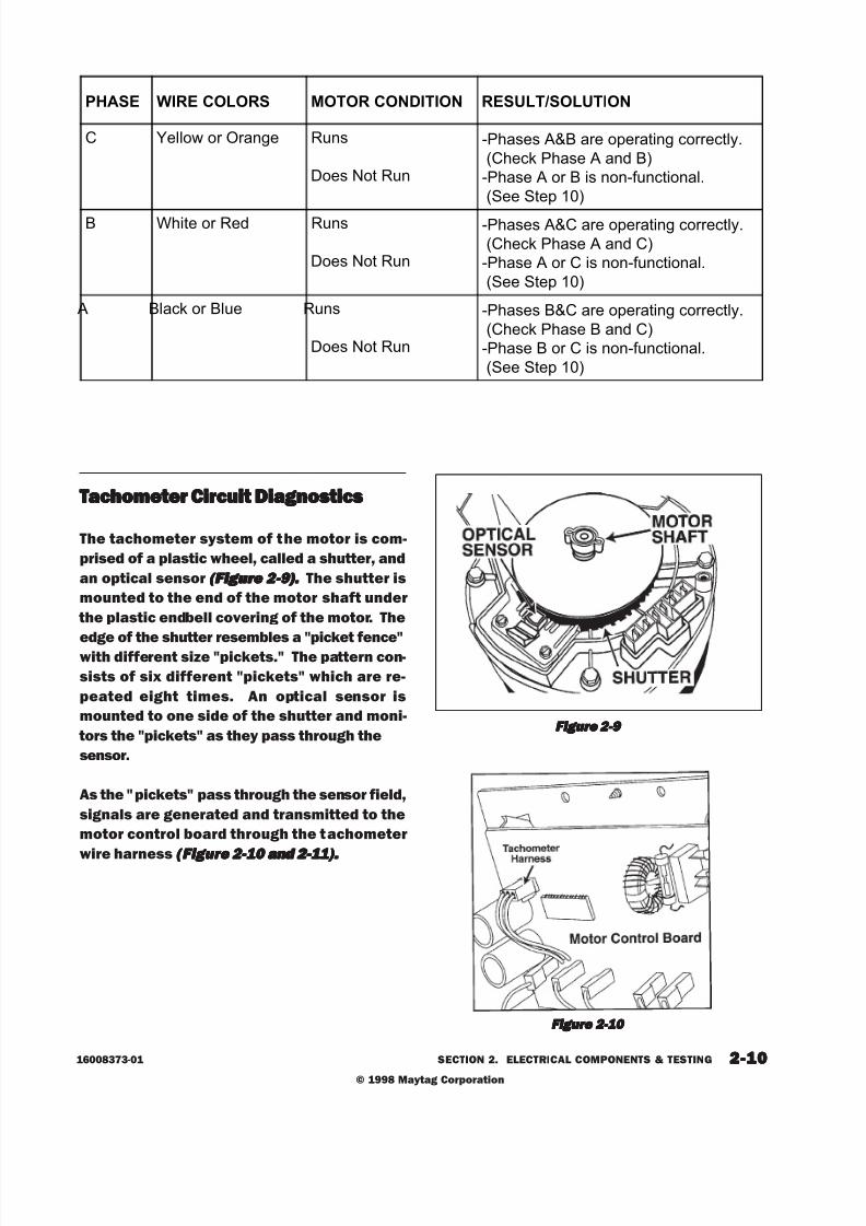
8/3/2019 Maytag MAH3000AWW Service Manual
http://slidepdf.com/reader/full/maytag-mah3000aww-service-manual 30/157
© 1998 Maytag Corporation
16008373-01 SECTION 2. ELECTRICAL COMPONENTS & TESTING 2-102-102-102-102-10
TTTTTachometer Cirachometer Cirachometer Cirachometer Cirachometer Circuit Diagnosticscuit Diagnosticscuit Diagnosticscuit Diagnosticscuit Diagnostics
The tachometer system of the motor is com-
prised of a plastic wheel, called a shutter, and
an optical sensor (Figure 2-9).(Figure 2-9).(Figure 2-9).(Figure 2-9).(Figure 2-9) . The shutter is
mounted to the end of the motor shaft under
the plastic endbell covering of the motor. The
edge of the shutter resembles a "picket fence"with different size "pickets." The pattern con-
sists of six different "pickets" which are re-
peated eight times. An optical sensor is
mounted to one side of the shutter and moni-
tors the "pickets" as they pass through the
sensor.
As the "pickets" pass through the sensor field,
signals are generated and transmitted to the
motor control board through the tachometer
wire harness (Figure 2-10 and 2-11).(Figure 2-10 and 2-11).(Figure 2-10 and 2-11).(Figure 2-10 and 2-11).(Figure 2-10 and 2-11).
Figure 2-9 Figure 2-9 Figure 2-9 Figure 2-9 Figure 2-9
Figure 2-10 Figure 2-10 Figure 2-10 Figure 2-10 Figure 2-10
PHASE WIRE COLORS MOTOR CONDITION RESULT/SOLUTION
C Yellow or Orange Runs
Does Not Run
-Phases A&B are operating correctly.
(Check Phase A and B)
-Phase A or B is non-functional.
(See Step 10)
B White or Red Runs
Does Not Run
-Phases A&C are operating correctly.
(Check Phase A and C)
-Phase A or C is non-functional.
(See Step 10)
A Black or Blue Runs
Does Not Run
-Phases B&C are operating correctly.
(Check Phase B and C)
-Phase B or C is non-functional.
(See Step 10)

8/3/2019 Maytag MAH3000AWW Service Manual
http://slidepdf.com/reader/full/maytag-mah3000aww-service-manual 31/157
© 1998 Maytag Corporation
2-112-112-112-112-1116008373-01 SECTION 2. ELECTRICAL COMPONENTS & TESTING
The motor control monitors the signals and
communicates this information to the ma-chine control. The purpose of this signal is to
tell the motor when to energize each winding
in the motor and to tell the machine control
the actual motor speed.
Note:Note:Note:Note:Note: If the machine control board does not If the machine control board does not If the machine control board does not If the machine control board does not If the machine control board does not
receive an input signal from the motor con- receive an input signal from the motor con- receive an input signal from the motor con- receive an input signal from the motor con- receive an input signal from the motor con-
trol/tachometer circuit ( JP4 connector), the trol/tachometer circuit (JP4 connector), the trol/tachometer circuit ( JP4 connector), the trol/tachometer circuit (JP4 connector), the trol/tachometer circuit ( JP4 connector), the
motor speed will rapidly accelerate for 5 sec- motor speed will rapidly accelerate for 5 sec- motor speed will rapidly accelerate for 5 sec- motor speed will rapidly accelerate for 5 sec- motor speed will rapidly accelerate for 5 sec-
onds then shut down. The machine control onds then shut down. The machine control onds then shut down. The machine control onds then shut down. The machine control onds then shut down. The machine control
will sense a "locked rotor" condition and the will sense a "locked rotor" condition and the will sense a "locked rotor" condition and the will sense a "locked rotor" condition and the will sense a "locked rotor" condition and the motor will stop. If the motor control does motor will stop. If the motor control does motor will stop. If the motor control does motor will stop. If the motor control does motor will stop. If the motor control does
not r not r not r not r not r eceive an input signal fr eceive an input signal fr eceive an input signal fr eceive an input signal fr eceive an input signal fr om the motor om the motor om the motor om the motor om the motor ,,,,,
the motor will " jerk" for 5 seconds then shut the motor will " jerk" for 5 seconds then shut the motor will " jerk" for 5 seconds then shut the motor will " jerk" for 5 seconds then shut the motor will " jerk" for 5 seconds then shut
down.down.down.down.down.
1. Inspect the motor control wire harness for
integrity of the connections on both ends.
The harness is comprised of a White, Blue
and Black wire.
2. Set the washer into the Delay Wash cycleand press the start/off button. The unit will
start without activating the motor. Leave
the tachometer harness on the motor con-
trol and insert the meter probes into the
back side of the tachommeter harness.
Figure 2-11 Figure 2-11 Figure 2-11 Figure 2-11 Figure 2-11
Tachometer
Wire ChecksVoltage Found
Condition Of
Component
White to Black
(From Motor
Control)
11 VDC
(± 2.5 VDC)
Good Motor
Control Board
White To Black
(From Motor
Control)
0 VDCBad Motor
Control Board
White To Black
(From Motor
Control)
+ 13 VDC or
<9 VDCBad Motor
Blue to Black(From Drive
Motor)
No change in
DC volts asmotor is turned
slowly
Bad Motor
Blue to Black
(From Drive
Motor)
Voltage
changes from 0
- 5 VDC volts as
motor is turned
slowly.
Good Motor
UNBALANCE CONTROL SYSTEMUNBALANCE CONTROL SYSTEMUNBALANCE CONTROL SYSTEMUNBALANCE CONTROL SYSTEMUNBALANCE CONTROL SYSTEM
The unbalance control system is comprised
of the inertial switch, outer tub displacement
switch, strut displacement switch and a cabi-
net vibration sensor mounted to the machine
control board. The three switches are wired
in series on a 24 VDC circuit, monitored by
the machine control board. The sensor is
mounted on the machine control board.
Software in the machine control board will
begin monitoring the switches when the spin
speed reaches 90 rpm. The inertial unbalance
switch monitors outer tub vibrations above
150 rpm. Inside the door is a cabinet vibra-
tion absorber designed to counter the vibra-
tion of the tub and serve as a tuned absorber
for the whole washer.
The following table indicates voltage checks
of the tachometer harness between the mo-
tor and motor control board.

8/3/2019 Maytag MAH3000AWW Service Manual
http://slidepdf.com/reader/full/maytag-mah3000aww-service-manual 32/157
© 1 9 9 8 M a y t a g C o r p o r a t i o n
16 0 0 8 3 7 3 - 0 1 SECTION 2. ELECT RICA L COMPONENTS & TEST ING 2 - 1 2
R P M F U N C T I O N
4 7 ... .. .. .. .. .. .. .. .. .. .. .. ..T u mb l e
47 - 85 ... .. .. .. .. .. .. .. .. .. ..Di s t r ib ut io n90- 250 .. ...... ....... ......A cce l e r a t e Th r ou gh
Cr it ical250- 4 99 ..... ....... ......A cce l e r a t e Th r ou gh
Cr it ical500 - 575 ..... ....... ......H igh S pee d Ac ce l e r a t ion
- WILL DROP TO 450 RPM
600 - 675 ..... ....... ......H igh S pee d Ac ce l e r a t ion- WILL DROP TO 555 RPM
> 6 7 5 .... ...... ....... ......H igh Spe ed A cce l e r a t ion- WILL DROP TO 650 RPM
75 0- 80 0 .............T OP SP IN S PEED
F ig u r e 2 - 12
S t r u t D i s p l a c e m e n t S w i t c h
T h e s t r u t d i s p l a c e m e n t s w i t c h i s c l i p p e d t o t h e
t o p o f t h e l e f t r e a r s t r u t . T h e s w it ch s e ns e s
t h e o u t e r t u b b o t t o m i n g o u t o n t h e s t r u t a s
t h e ma c h in e a c ce l e r a t e s a b o v e 9 0 r p m. T h i s
i s c a u s e d b y t h e t w i s t i n g m o t i o n o f t h e o u t e r
t ub . Th is add it i ona l swi t ch i s r equ ir ed becauset h e t w i s t i n g m o t i o n m a y n o t t r i p t h e o u t e r t u b
d i s p l a ce me n t s w i t c h . T h e p r i m a r y c a u s e f o r
a c t i v a t i o n w o u l d b e a n u n b a l a n c e a t t h e f r o n t
a n d r e a r o f t h e s p i n n e r o n o p p o s i t e s i d e s .
T h e s t r u t d i s p l a c e m e n t s w i t c h i s w i r e d i n s e -
r i e s w i t h t h e t u b d i s p l a c e m e n t s w i t c h a n d
c a u s e s t h e s a m e t y p e o f r e d i s t r i b u t i o n .
T e s t i n g t h e S t r u t D i s p l a c e m e n t S w i t c h :
1 . D i s c o n n e c t p o w e r t o t h e u n i t .
2 . P la ce oh m me t e r l e ad s acr o s s t h e t w o t e r -
mi na l s o f t h e s w i t c h . De p r e s s t h e b u t t o n
o n t h e s w i t c h . If t h e c on t a ct s cl o s e , t h e
s w i t c h i s g o od . If n o t , r e p l a ce t h e s w i t c h.
T u b D i s p l a c e m e n t S w i t c h
T h e t u b d i s p l a c e m e n t s w i t c h i s l o c a t e d o n t h e
u p p e r r i g h t h a n d s i d e o f t h e o u t e r t u b , b e l o w
t h e t o p c o n c r e t e w e i g h t , b e t w e e n t h e o u t e r
t u b a n d t h e c ab in e t . T h e s w i t c h s e n s e s t h e
o u t e r t u b t o u c h i n g t h e c a b i n e t s i d e a s t h ema c h in e p a s s e s t h r o u g h c r i t i c al . W h e n t h i s
s w i t c h i s t r i p p e d , t h e m a c h i n e s t o p s a n d r e -
d i s t r i b u t e s t h e l o a d .
T e s t i n g t h e T u b D i s p l a c e m e n t S w i t c h :
1 . D i s c o n n e c t p o w e r t o t h e u n i t .
2 . P la ce oh m me t e r l e ad s acr o s s t h e t w o t e r -
mi na l s o f t h e s w i t c h . De p r e s s t h e b u t t o n
o n t h e s w i t c h . If t h e c o nt a ct s o p e n, t h es w i t c h i s g o od . If n o t , r e p l a ce t h e s w i t c h.
W h en e v e r a d i s p l a ce me n t s w i t c h is t r i pp e d ,
t h e m a c h i n e s t o p s a n d r e d i s t r i b u t e s t h e
c lo t hes load . Th is i nvo lves a t h r ee (3 ) second
p a u s e , f o l l o we d b y a f i v e ( 5 ) s e c o n d r e v e r s e
t u mb l e (4 7 - 4 9 r p m) t o r e d is t r i bu t e t h e cl o t h e s
l o a d . T h e w a s h e r w il l pa u s e a g a in f o r t h r e e
( 3 ) s e c o n d s , t h e n s t a r t t h e d i s t r i b u t i o n p r o f i l e
a g a in . T o r e d i s t r i b u t e t h e l o a d , t h e ma c hi n e
t u mb l e s t h e l o a d (5 0 - 9 0 r p m ) a n d a ga i n a t -
t e m p t s t o p a s s t h r o u g h c r i t i c a l ( a b o u t 1 5 0
r p m) . T h e ma ch in e w i l l t r y t o r e d is t r i b u t e
t w i c e a s t h e w a s h e r a t t e m p t s t o s p i n a t 8 0 0
r p m .
O n c e t h e l o a d i s p r o p e r l y r e d i s t r i b u t e d a n d
t h e s p e e d r e a ch e s a b o v e 50 0 r p m , t h e i ne r t i a l
s w i t c h a n d c a b i n e t v i b r a t i o n s e n s o r a r e u s e d .
I f the ine r t i a l sw i tch o r sensor i s ac t i va ted , the
washer w i l l d rop in sp in speed . Th is i s based
u p o n t h e s p e e d a t w h i c h s w i t c h a c t i v a t i o n
t akes p lace. See Figure 2- 12 ou t l i n ing the sp in
s p e e d c a t e g o r i e s a n d t h e c or r e s p o n di n g r e -
d u ce d s p e e d s . If t h e s w i t c h es a r e no t a c t i -
v a t e d , t h e f i n al s p i n s p e e d w il l r e a ch a ma x i -
m u m o f 8 5 0 r p m a n d t h e n d r o p t o f i n d t h e
o p t i mu m p e r f o r m a n c e l e v e l , b a s e d u p o n
r e a d i n g s t a k e n b y t h e c a b i n e t v i b r a t i o n s e n -
s o r . Co n s u m er s ma y b e c o n f u s e d b y t h e u p -
a n d - d o w n c y cl i n g o f t h e mo t o r . Ho w e v e r , t h e
m a c h i n e i s s e a r c h i n g f o r t h e o p t i m a l s p e e d
p e r f o r m a n c e .

8/3/2019 Maytag MAH3000AWW Service Manual
http://slidepdf.com/reader/full/maytag-mah3000aww-service-manual 33/157
© 19 9 8 M a y t a g C o r p o r a t i o n
2 - 1 316 0 0 8 3 7 3 - 0 1 SECT ION 2. ELECT RICA L COMPONENTS & T EST ING
C a b i n e t V i b r a t i o n S e n s o r
T h e c a b i n e t v i b r a t i o n s e n s o r i s m o u n t e d t o t h e
l o w e r l e f t c o r n e r o f t h e m a c h i n e c o n t r o l
b o a r d . T h i s i s a p ie z o - e l e ct r i c s t r i p mo u nt e dt o t h e ma c hi n e c o nt r o l b o a r d . W it h a ma s s
a t t a c h e d t o t h e e n d o f t h e s t r i p , t h e m a c h i n e
c o n t r o l l e r m o n i t o r s t h e c a b i n e t v i b r a t i o n a s
t h e m ac h i n e r e a c h e s t o p s p e e d . T h e ma c h i ne
c o n t r o l l e r u s e s t h e v i b r a t i o n s e n s o r t o a t t e m p t
t o s p i n t h e wa s h e r a t t h e o p t i m u m s p e e d w i t h
t h e l e a s t a mo u n t o f v i b r a t i o n. Op t i mu m s p e e d
c h a n ge s f r o m ma c h in e t o ma c h in e d u e t o :
c h a ng e s i n ma s s o f t h e a b s o r b e r ; ch a n g e s i n
C a b i n e t V i b r a t i o n A b s o r b e r
T h i s i s a t u n e d a b s o r b e r m o u n t e d i n t h e d o o r .
T h e t u n e d a b s o r b e r c o n s i s t s o f a m a s s s u s -
p e n d e d b y s p r i n g s t u n e d t o v i b r a t e a t a p p r o x i -
ma t e l y 8 0 0 r p m. T h e ma s s v i b r a t e s 18 0 d e -
g r e e s o u t o f p h a s e w i t h t h e v i b r a t i o n o f t h e
c a b in e t . T h i s c a nc e l s o u t mu c h o f t h e v i b r a -
t i on caused by the c lo thes load a t 800 rpm (See
S e c t i o n 5 : Ca b i n e t A s s e m b l y ) .
I n e r t i a l U n b a l a n c e S w i t c h
T h e i n e r t i a l u n b a l a n c e s w i t c h i s l o c a t e d o n t h e
u p p e r r i g h t h a n d s i d e o f t h e o u t e r t u b , i n f r o n t
o f t h e t o p c on cr e t e w e ig h t . T h e s w i t c h c on -
s i s t s o f a m o v i n g w e i g h t i n t h e s w i t c h b o d y
wh i ch p r e s s e s a g a in s t t h e s w i t c h c o nt a c t s . Ift h e u n b a l a n c e o f t h e o u t e r t u b b e c o m e s t o o
e r r a t i c, t h e mo v i n g w ei g ht w i l l o p e n t h e c o n -
t a c t s i n t h e s w i t c h . W h e n t h e ma c hi n e c o n-
t r o l l e r s e n s e s t h e s w i t c h o p e n i n g , t h e m a c h i n e
c o n t r o l l e r w i l l r e d u c e t h e s p i n s p e e d t o 6 5 0 ,
5 5 0 , o r 4 5 0 r p m d e p e n d i n g o n t h e c u r r e n t
speed c loses t to the leve l sp in speed ( i .e . 625
r p m t r i p w o u l d d r o p t o 5 5 0 r p m ) ( See F igu r e
2 - 12 ) .
T e s t i n g t h e I n e r t i a l U n b a l a n c e S w i t c h :
T e s t i n g o f t h e s w i t c h m a y p r o v e d i f f i c u l t . T h e
s w i t c h w i l l n o t o p e n u n l e s s t h e s w i t c h i s
moved s ide to s ide cr ea t ing a "G" f o rce o f 8 - 9
F t . l bs .
1 . D i s c o n n e c t p o w e r t o t h e u n i t .
2 . P la ce oh m me t e r l e ad s acr o s s t h e t w o t e r -
mi n al s of t h e i ne r t i a l s w i t c h. Mo v e t h e
swi tch s ide t o s ide. If t he con t act s do no t
o p e n e a s i l y , t h e s w i t c h i s g o o d. If t h e
s w i t c h c o n t a c t s a r e o p e n o r e a s i l y t r i p p e d ,
r e p l a c e t h e s w i t c h .
s p r i n g r a t e o f t h e a b s o r b e r ; a n d c h a n g e s i n
t h e p u l l e y - b e l t r a t i o. It c a n a l s o c ha n ge f r o m
r u n t o r u n d u e t o t h e s i z e o f t h e c l o t h e s l o a d
a n d t y p e o f f l o o r . T h e s e n s or f i nd s t h e o p t i -
mum speed on ever y run . The op t imum speed
i s b e t we e n 7 5 0 a n d 8 5 0 r p m .

8/3/2019 Maytag MAH3000AWW Service Manual
http://slidepdf.com/reader/full/maytag-mah3000aww-service-manual 34/157
© 1 9 9 8 M a y t a g C o r p o r a t i o n
16 0 0 8 3 7 3 - 0 1 SECTION 2. ELECT RICA L COMPONENTS & TEST ING 2 - 1 4

8/3/2019 Maytag MAH3000AWW Service Manual
http://slidepdf.com/reader/full/maytag-mah3000aww-service-manual 35/157

8/3/2019 Maytag MAH3000AWW Service Manual
http://slidepdf.com/reader/full/maytag-mah3000aww-service-manual 36/157
© 1998 Maytag Corporation
16 008373-0 1 SECTION 3. TROUBLESHOOTING 3 - 23 - 23 - 23 - 23 - 2
Excessive Vibration:Excessive Vibration:Excessive Vibration:Excessive Vibration:Excessive Vibration:
Ensure that shipping bolts and straps have
been removed from the washer. Check the
levelness of the washer and ensure the level-
ing leg nuts are tightened up against the cabi-
net. Check the tightness of the upper and
lower weights on the outer tub. Check for
loose cabinet screws. Place hand on side of
cabinet to determine if vibration noise due to
cabinet flex. Apply sound dampening pad to
inner cabinet wall if necessary. Check the un-
balance circuit and wiring for continuity at the
machine control (P2(4) to P3(1). Continuity
should be present. If not, check the wiring
connections at the strut, outer tub and interial
unbalance switches. If a switch is bad or a
wire off, the machine control will not know
when an unbalance occurs. The machine con-
trol board checks the state of the circuit prior
to beginning the spin cycle, then monitors the
circuit throughout the cycle. If the circuit is
OPEN, the board will not see “a change in
state” whenever one of the normally-closed
switches is activated during an unbalanced
load condit ion.
Machine Operation Does Not Match CycleMachine Operation Does Not Match CycleMachine Operation Does Not Match CycleMachine Operation Does Not Match CycleMachine Operation Does Not Match Cycle
Descr ipt i on :Descr ipt i on :Descr ipt i on :Descr ipt i on :Descr ipt i on :
The machine control board monitors where
the timer is in the cycle and then uses this in-
formation to start different operations, such
as drain, fill, tumble and spin. Four input wires
from the timer to the machine control board
inform the machine control board where the
timer is in the wash cycle. However, if one or
more of these wires are making an intermittant
contact with the machine control board, the
board can be “misinformed” and will not re-spond properly.
Check the connections of the timer input wires
leading from the timer to the machine con-
trol board (See Sect ion 2: T imer Input (See Sect ion 2: T imer Input (See Sect ion 2: T imer Input (See Sect ion 2: T imer Input (See Sect ion 2: T imer Input
Charts).Charts).Charts).Charts).Charts). Also, check wiring of all console
switches to ensure no cross-wiring of 24 VDC
and 120 VAC circuits.
Tumbles Only:
When the door lock mechanism is in the
"locked" mode, the wax motor has extended,
forcing the latch axle to engage the door lock
enable switch. This ensures the door is fully
locked and the switch can then complete the
signal back to the machine control board in-
dicating the door is locked. Check connector
P3(7)/YL 36 wire to verify if the terminal is
making good contact to the board terminal.
Check the door lock enable switch for conti-
nuity when the button is depressed. Replace
door lock mechanism if necessary.
ContinuesTo Tumble After The Wash Cycle
Is Finished:
Check for a stuck button on the door lock en-
able switch in the door lock mechanism. You
can verify this at the machine control board
by checking for continuity across P3(7)/YL 36
to P3(1)/RD23. If the door is unlocked and
there is continuity, the switch button is stuck.
At the end of the wash cycle, the machine con-
trol monitors the door lock enable switch for
disengagement. If the switch is stuck, the
washer will continue to tumble till the door
unlocks, even though the door is actually un-
locked. Replace the door lock mechanism.
Third Rinse Cycle Is Always Cold:Third Rinse Cycle Is Always Cold:Third Rinse Cycle Is Always Cold:Third Rinse Cycle Is Always Cold:Third Rinse Cycle Is Always Cold:
If the user rotates the timer dial to the third or
fourth rinse, the water will always be cold re-
gardless of temperature selection. The ma-
chine control board counts the number of
rinses through the wash cycle. When the third
and fourth rinse are reached, the board will
check the rinse temperature selection forproper fill temperature (See Section 1:Water (See Section 1:Water (See Section 1:Water (See Section 1:Water (See Section 1:Water
Temperature Inputs).Temperature Inputs).Temperature Inputs).Temperature Inputs).Temperature Inputs).

8/3/2019 Maytag MAH3000AWW Service Manual
http://slidepdf.com/reader/full/maytag-mah3000aww-service-manual 37/157
© 1998 Maytag Corporation
1 6008373-0 1 SECTION 3. TROUBLESHOOTING 3 - 33 - 33 - 33 - 33 - 3
Door Leaks:Door Leaks:Door Leaks:Door Leaks:Door Leaks:
Usually this occurs when the door is re-
mounted into the shroud and the technician
fully tightens the top hinge screw prior to in-
serting the lower screw. The technician should
fully seat the door into the shroud evenly prior
to tightening the hinge bracket screw into the
shroud. Check also for excess plastic flashing
in the tab area of the plastic shroud. Care-
fully remove the excess flash and remount the
boot gasket.
“Thumping” No ise In Sp in“Thumping” No ise In Sp in“Thumping” No ise In Sp in“Thumping” No ise In Sp in“Thumping” No ise In Sp in :::::
The noise could be from loose lower front
weight mounting bolts or a loose bolt secur-
ing the driven pulley. Check the belt for a weak
seam and replace if necessary. Check the
motor adjustment bolt for tightness.
"Ticking or Knocking" Noise In Spin"Ticking or Knocking" Noise In Spin"Ticking or Knocking" Noise In Spin"Ticking or Knocking" Noise In Spin"Ticking or Knocking" Noise In Spin:::::
The noise could be from a loose wire harness,
plastic purse-lock wire harness retainer on
upper hose hitting the topcover or a plastic
injection mold standoff on the outer tub bear-
ing housing may possibly be interfering with
the driven pulley.
Also, check the drive belt for a weak spot on
the belt. Ussually felt on the backside of the
belt as a "flat" spot. Replace the belt.
RF (Radio Frequency) Interference:RF (Radio Frequency) Interference:RF (Radio Frequency) Interference:RF (Radio Frequency) Interference:RF (Radio Frequency) Interference:
The interference could occur if the RPT shut-
ter on the motor was misaligned or a motor
terminal has been pushed inward sl ightly
when the motor harness connector wasplaced on the motor. Remove the motor phase
harness connector and check the motor ter-
minals. Replace the motor if the motor
teminals are loose.
Dispenser Does Not DispenseDispenser Does Not DispenseDispenser Does Not DispenseDispenser Does Not DispenseDispenser Does Not Dispense:::::
Examine the siphon cap to see if the cap was
twisted, causing the cap to seal the siphon
tube against the bottom of the siphon cup. Re-
position cap to lift the siphon tube off the bot-
tom of the cup. The wax motors are activated
a full 30 seconds prior to turning on the water
valves. If the timing is not correct, suspect a
bad wiring connection. Also, examine the link-
age of the acutuator arm and proper location
of the spring on the wax motor (See Section (See Section (See Section (See Section (See Section
6: Water Carrying Components).6: Water Carrying Components).6: Water Carrying Components).6: Water Carrying Components).6: Water Carrying Components).
Clothes Wet:Clothes Wet:Clothes Wet:Clothes Wet:Clothes Wet:
Possibly due to the washer shutting down too
soon or execessive suds present. Did the timer
advance to OFF? If yes, then excessive suds
may be the cause or the intertial unbalance
switch tripped too soon, resulting in lower spin
speeds. Change the inertial switch if suds were
not detected. Note:Note:Note:Note:Note: If the timer motor is en-If the timer motor is en-If the timer motor is en-If the timer motor is en-If the timer motor is en-
ergized for five minutes without the cycle in-ergized for five minutes without the cycle in-ergized for five minutes without the cycle in-ergized for five minutes without the cycle in-ergized for five minutes without the cycle in-
puts changing, the machine control board will puts changing, the machine control board will puts changing, the machine control board will puts changing, the machine control board will puts changing, the machine control board will
drop the line voltage relay.drop the line voltage relay.drop the line voltage relay.drop the line voltage relay.drop the line voltage relay.

8/3/2019 Maytag MAH3000AWW Service Manual
http://slidepdf.com/reader/full/maytag-mah3000aww-service-manual 38/157
© 1998 Maytag Corporation
16 008373-0 1 SECTION 3. TROUBLESHOOTING 3 - 43 - 43 - 43 - 43 - 4
T R O U B L E S H O O T I N GT R O U B L E S H O O T I N GT R O U B L E S H O O T I N GT R O U B L E S H O O T I N GT R O U B L E S H O O T I N G

8/3/2019 Maytag MAH3000AWW Service Manual
http://slidepdf.com/reader/full/maytag-mah3000aww-service-manual 39/157
© 1998 Maytag Corporation
1 6008373-0 1 SECTION 3. TROUBLESHOOTING 3 - 53 - 53 - 53 - 53 - 5
T R O U B L E S H O O T I N GT R O U B L E S H O O T I N GT R O U B L E S H O O T I N GT R O U B L E S H O O T I N GT R O U B L E S H O O T I N G

8/3/2019 Maytag MAH3000AWW Service Manual
http://slidepdf.com/reader/full/maytag-mah3000aww-service-manual 40/157
© 1998 Maytag Corporation
16 008373-0 1 SECTION 3. TROUBLESHOOTING 3 - 63 - 63 - 63 - 63 - 6
T R O U B L E S H O O T I N GT R O U B L E S H O O T I N GT R O U B L E S H O O T I N GT R O U B L E S H O O T I N GT R O U B L E S H O O T I N G

8/3/2019 Maytag MAH3000AWW Service Manual
http://slidepdf.com/reader/full/maytag-mah3000aww-service-manual 41/157
© 1998 Maytag Corporation
1 6008373-0 1 SECTION 3. TROUBLESHOOTING 3 - 73 - 73 - 73 - 73 - 7
T R O U B L E S H O O T I N GT R O U B L E S H O O T I N GT R O U B L E S H O O T I N GT R O U B L E S H O O T I N GT R O U B L E S H O O T I N G

8/3/2019 Maytag MAH3000AWW Service Manual
http://slidepdf.com/reader/full/maytag-mah3000aww-service-manual 42/157
© 1998 Maytag Corporation
16 008373-0 1 SECTION 3. TROUBLESHOOTING 3 - 83 - 83 - 83 - 83 - 8
T R O U B L E S H O O T I N GT R O U B L E S H O O T I N GT R O U B L E S H O O T I N GT R O U B L E S H O O T I N GT R O U B L E S H O O T I N G
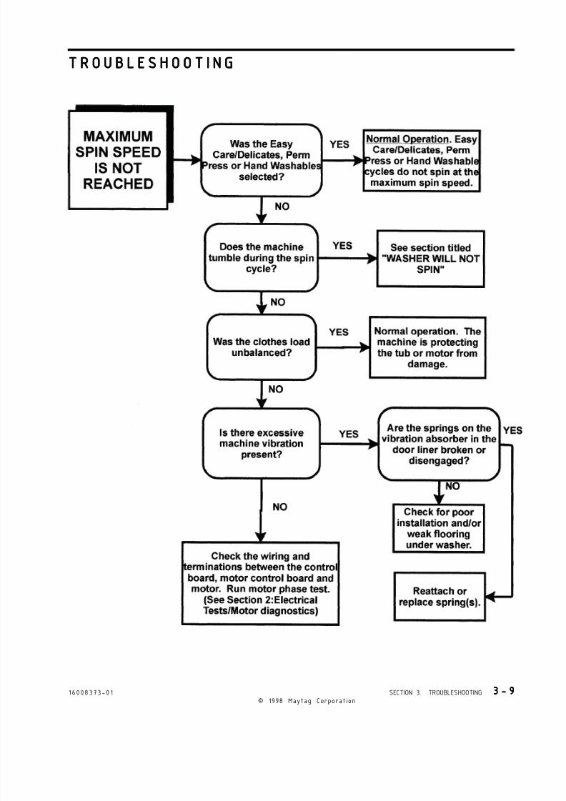
8/3/2019 Maytag MAH3000AWW Service Manual
http://slidepdf.com/reader/full/maytag-mah3000aww-service-manual 43/157
© 1998 Maytag Corporation
1 6008373-0 1 SECTION 3. TROUBLESHOOTING 3 - 93 - 93 - 93 - 93 - 9
T R O U B L E S H O O T I N GT R O U B L E S H O O T I N GT R O U B L E S H O O T I N GT R O U B L E S H O O T I N GT R O U B L E S H O O T I N G

8/3/2019 Maytag MAH3000AWW Service Manual
http://slidepdf.com/reader/full/maytag-mah3000aww-service-manual 44/157
© 1998 Maytag Corporation
16 008373-0 1 SECTION 3. TROUBLESHOOTING 3 - 1 03 - 1 03 - 1 03 - 1 03 - 1 0
T R O U B L E S H O O T I N GT R O U B L E S H O O T I N GT R O U B L E S H O O T I N GT R O U B L E S H O O T I N GT R O U B L E S H O O T I N G

8/3/2019 Maytag MAH3000AWW Service Manual
http://slidepdf.com/reader/full/maytag-mah3000aww-service-manual 45/157
© 1998 Maytag Corporation
1 6008373-0 1 SECTION 3. TROUBLESHOOTING 3 - 1 13 - 1 13 - 1 13 - 1 13 - 1 1
T R O U B L E S H O O T I N GT R O U B L E S H O O T I N GT R O U B L E S H O O T I N GT R O U B L E S H O O T I N GT R O U B L E S H O O T I N G

8/3/2019 Maytag MAH3000AWW Service Manual
http://slidepdf.com/reader/full/maytag-mah3000aww-service-manual 46/157
© 1998 Maytag Corporation
16 008373-0 1 SECTION 3. TROUBLESHOOTING 3 - 1 23 - 1 23 - 1 23 - 1 23 - 1 2
T R O U B L E S H O O T I N GT R O U B L E S H O O T I N GT R O U B L E S H O O T I N GT R O U B L E S H O O T I N GT R O U B L E S H O O T I N G

8/3/2019 Maytag MAH3000AWW Service Manual
http://slidepdf.com/reader/full/maytag-mah3000aww-service-manual 47/157
© 1998 Maytag Corporation
1 6008373-0 1 SECTION 3. TROUBLESHOOTING 3 - 1 33 - 1 33 - 1 33 - 1 33 - 1 3
T R O U B L E S H O O T I N GT R O U B L E S H O O T I N GT R O U B L E S H O O T I N GT R O U B L E S H O O T I N GT R O U B L E S H O O T I N G
Use a knife or scissors to cut across the + in the center of the dial and press the template over
the timer shaft. Align the template with the OFF indicators of the Quick Wash and Regular wash
on the facia. Press the timer knob onto the timer shaft.

8/3/2019 Maytag MAH3000AWW Service Manual
http://slidepdf.com/reader/full/maytag-mah3000aww-service-manual 48/157
© 1998 Maytag Corporation
16 008373-0 1 SECTION 3. TROUBLESHOOTING 3 - 1 43 - 1 43 - 1 43 - 1 43 - 1 4
Energy UsageEnergy UsageEnergy UsageEnergy UsageEnergy Usage :::::
The energy usage averages up to 0.10 Kwh per cycle, when using the Regular cycle with Nor-
mal wash. Peak amperage is 7.5 amps during acceleration to high speed spin, with nominal
running amperage at a maximum of 5.0 amps.
Washer WattagesWasher WattagesWasher WattagesWasher WattagesWasher Wattages :::::
The following wattages are approximate and without clothes:
F u n c t i o n :F u n c t i o n :F u n c t i o n :F u n c t i o n :F u n c t i o n : Wattages:Wattages:Wattages:Wattages:Wattages:
De la y 10-15
Tumbling (empty) & water fill 50-70
Tumbling (Full-Wash level) 110-120
Tumbling (Full-Rinse Level) 140-150
Draining (No tumble) with water 45-50Dra in ing (No tumble) no water 30-35
Spinn ing (100 rpm) 85-90
Spin Acceleration (100-200 rpm) 130-150
Spinning (400 rpm) 160-170
Spinning (850 rpm) 400-410
MISCELLANEOUS INFORMATIONMISCELLANEOUS INFORMATIONMISCELLANEOUS INFORMATIONMISCELLANEOUS INFORMATIONMISCELLANEOUS INFORMATION

8/3/2019 Maytag MAH3000AWW Service Manual
http://slidepdf.com/reader/full/maytag-mah3000aww-service-manual 49/157© 1998 Maytag Corporation
16 008373-0 1 SECTION 4. CONSOLE 4 - 14 - 14 - 14 - 14 - 1
SECTION 4 . CONSOLESECTION 4 . CONSOLESECTION 4 . CONSOLESECTION 4 . CONSOLESECTION 4 . CONSOLE
R E M O V A LR E M O V A LR E M O V A LR E M O V A LR E M O V A L
1 . Disconnect power to the unit.Disconnect power to the unit.Disconnect power to the unit.Disconnect power to the unit.Disconnect power to the unit.
2 . Remove the three screws securing the con-
sole rear cover plate across the rear top
edge of the console (Figure 4-1) (Figure 4-1) (Figure 4-1) (Figure 4-1) (Figure 4-1) .....
3 . Lay a drop cloth across the top cover of thewasher.
4 . Grasp the top of the console and gently rock
the top forward ( Figure 4-2 Figure 4-2 Figure 4-2 Figure 4-2 Figure 4-2).
Warning Warning Warning Warning Warning - Always shut off- Always shut off- Always shut off- Always shut off- Always shut off
electrical power to the unitelectrical power to the unitelectrical power to the unitelectrical power to the unitelectrical power to the unit
before beginning any servicebefore beginning any servicebefore beginning any servicebefore beginning any servicebefore beginning any service
procedure .procedure .procedure .procedure .procedure .
Figure 4-2 Figure 4-2 Figure 4-2 Figure 4-2 Figure 4-2
Figure 4-3 Figure 4-3 Figure 4-3 Figure 4-3 Figure 4-3
Figure 4-4Figure 4-4Figure 4-4Figure 4-4Figure 4-4
Figure 4-1 Figure 4-1 Figure 4-1 Figure 4-1 Figure 4-1
C o n s o l eC o n s o l eC o n s o l eC o n s o l eC o n s o l e
M o u n t i n gM o u n t i n gM o u n t i n gM o u n t i n gM o u n t i n g
S c r ewsS c r ewsS c r ewsS c r ewsS c r ews
5 . Push the bottom of the console toward
the back panel to disengage the six lock-
ing feet from the top cover (Figure 4-3) (Figure 4-3) (Figure 4-3) (Figure 4-3) (Figure 4-3) .
6 . Carefully lift and roll the console forward
onto the top cover. You now have access
to the console components and wiring
(Figure 4-4).(Figure 4-4).(Figure 4-4).(Figure 4-4).(Figure 4-4).
7 . To Reinstall:To Reinstall:To Reinstall:To Reinstall:To Reinstall: Roll the console back into
an upright position, engaging the locking
feet into the slots in the top cover. Re-
place the three screws to attach console
back to rear panel.

8/3/2019 Maytag MAH3000AWW Service Manual
http://slidepdf.com/reader/full/maytag-mah3000aww-service-manual 50/157© 1998 Maytag Corporation
160 08373-0 1 SECTION 4. CONSOLE 4 - 24 - 24 - 24 - 24 - 2
R E M O V A LR E M O V A LR E M O V A LR E M O V A LR E M O V A L
Depress the tab at the top of the switch with
a screwdriver to disengage the tab from theconsole. Pivot the switch away from the
console to remove (Figure 4-5) (Figure 4-5) (Figure 4-5) (Figure 4-5) (Figure 4-5) .
R E P L A C E M E N TR E P L A C E M E N TR E P L A C E M E N TR E P L A C E M E N TR E P L A C E M E N T
Align the rib on the bottom of the switch with
the slot in the console. Pivot the switch up
into the console until the tab engages the
console securely. Check that the locating tabs
on either side of the switch's lower alignment
rib are in position to properly center and lockthe switch into the lower part of the switch
o p e n i n g .
VERTICAL SWITCHESVERTICAL SWITCHESVERTICAL SWITCHESVERTICAL SWITCHESVERTICAL SWITCHES(Push Button)(Push Button)(Push Button)(Push Button)(Push Button)
HORIZONTAL SWITCHESHORIZONTAL SWITCHESHORIZONTAL SWITCHESHORIZONTAL SWITCHESHORIZONTAL SWITCHES
(Push-to-Start)(Push-to-Start)(Push-to-Start)(Push-to-Start)(Push-to-Start)
Locking Tab
Locking Tab
Locking Tab
Screwdr iver
Locking Tab
Carefully DepressCarefully DepressCarefully DepressCarefully DepressCarefully DepressLocking Tab onLocking Tab onLocking Tab onLocking Tab onLocking Tab on
Switch to DisengageSwitch to DisengageSwitch to DisengageSwitch to DisengageSwitch to DisengageFrom ConsoleFrom ConsoleFrom ConsoleFrom ConsoleFrom Console
Figure 4-6 Figure 4-6 Figure 4-6 Figure 4-6 Figure 4-6 Figure 4-5 Figure 4-5 Figure 4-5 Figure 4-5 Figure 4-5
Align the Center RibAlign the Center RibAlign the Center RibAlign the Center RibAlign the Center Ribon the bottom of theon the bottom of theon the bottom of theon the bottom of theon the bottom of theSwitch with the Slot inSwitch with the Slot inSwitch with the Slot inSwitch with the Slot inSwitch with the Slot inthe Cup on the Bottomthe Cup on the Bottomthe Cup on the Bottomthe Cup on the Bottomthe Cup on the Bottomof the Switch Openingof the Switch Openingof the Switch Openingof the Switch Openingof the Switch Openingon the Consoleon the Consoleon the Consoleon the Consoleon the Console
Pivoting thePivoting thePivoting thePivoting thePivoting theSwitch Body, LockSwitch Body, LockSwitch Body, LockSwitch Body, LockSwitch Body, Lockit in at the Top ofit in at the Top ofit in at the Top ofit in at the Top ofit in at the Top ofthe Openingthe Openingthe Openingthe Openingthe Openingon the Console.on the Console.on the Console.on the Console.on the Console.
R E M O V A LR E M O V A LR E M O V A LR E M O V A LR E M O V A L
Depress the locking tab on the switch to
disengage it from the locking tab on theconsole. Pivot the switch from the console
(Figure 4-6).(Figure 4-6).(Figure 4-6).(Figure 4-6).(Figure 4-6).
R E P L A C E M E N TR E P L A C E M E N TR E P L A C E M E N TR E P L A C E M E N TR E P L A C E M E N T
Position one side into the console and pivot
the other tab into the console and apply enough
pressure to engage the tab into the console.

8/3/2019 Maytag MAH3000AWW Service Manual
http://slidepdf.com/reader/full/maytag-mah3000aww-service-manual 51/157© 1998 Maytag Corporation
16 008373-0 1 SECTION 4. CONSOLE 4 - 34 - 34 - 34 - 34 - 3
1 . Disconnect power to the unit.Disconnect power to the unit.Disconnect power to the unit.Disconnect power to the unit.Disconnect power to the unit.
2 . Carefully lift the timer knob and dial off
the timer shaft by pulling the knob away
from the face of the control console
(Figure 4-7).(Figure 4-7).(Figure 4-7).(Figure 4-7).(Figure 4-7).
3 . Disengage the console assembly from
the top cover and roll forward (See (See (See (See (See
Console Removal) Console Removal) Console Removal) Console Removal) Console Removal) .
4. Remove timer mounting screw on back
of timer in the console.
5 . Slightly lift the locking tab on the back of
the timer (Figure 4-8).(Figure 4-8).(Figure 4-8).(Figure 4-8).(Figure 4-8).
6 . With the locking tab lifted, slide the timer
body toward the end cap of the console.
This will disengage the retaining tabs of
the timer from the slots in the console.
7 . Lift the timer away from the console.Figure 4-8 Figure 4-8 Figure 4-8 Figure 4-8 Figure 4-8
TIMER REMOVALTIMER REMOVALTIMER REMOVALTIMER REMOVALTIMER REMOVAL
Figure 4-7 Figure 4-7 Figure 4-7 Figure 4-7 Figure 4-7
R E P L A C E M E N TR E P L A C E M E N TR E P L A C E M E N TR E P L A C E M E N TR E P L A C E M E N T
1 . Align the three tabs of the timer into the
slots of the console.
2 . Insert the timer into the slots and
slightly lift the locking tab of the timer.
Slide the timer away from the endcap
until the locking tab can engage with the
square hole in the console.
3 . Rep la ce mount ing sc rew.

8/3/2019 Maytag MAH3000AWW Service Manual
http://slidepdf.com/reader/full/maytag-mah3000aww-service-manual 52/157© 1998 Maytag Corporation
160 08373-0 1 SECTION 4. CONSOLE 4 - 44 - 44 - 44 - 44 - 4

8/3/2019 Maytag MAH3000AWW Service Manual
http://slidepdf.com/reader/full/maytag-mah3000aww-service-manual 53/157
© 1998 Maytag Corporation
16008373-01 SECTION 5. CABINET ASSEMBLY 5-1
SECTION 5. CABINET ASSEMBLY
Warning - Always shut off
electrical power to the unit
before beginning any ser-vice repair procedures.
DOOR ASSEMBLY & HINGES
The door assembly is reversible. It contains
an inertial vibration damper comprised of a
steel plate suspended with springs. The
damper is designed to tune out excessive vi-
brations generated by the machine during the
spin cycle. Replacement inner door liners are
shipped with the vibration damper in place.
REMOVAL
1. Open the door and remove the center
screw of each hinge secured to the inner
flange of the front panel in the door
opening.
2. Grasp the door with both hands and lift
the hinge area slightly. Draw the door as-
sembly away from the machine. This will
disengage the hinges from the slots in the
front shroud (Figure 5-1). If the hinges
bind, press out on the plastic shroud near
the hinge toward the cabinet.
Figure 5-1
REVERSAL
1. Repeat the above steps and, remove the
corresponding sheet metal spacers on the
opposite side.
2. Remove the hinges from the door and re-
locate them to the other side of the door.
3. Remount the door into the new slots and
secure with one screw into each hinge.
4. Mount the sheet metal spacers onto the
side where the hinges were previously to
cover the hinge slots in the front shroud.
DISASSEMBLY
1. Remove ten screws located across the bot-
tom and along either side of the door
panel. The top edge of the outer panel is
folded over the inner door plug.
2. With the outer door panel removed, the
stabilizer is exposed and is attached to the
inner door plug.

8/3/2019 Maytag MAH3000AWW Service Manual
http://slidepdf.com/reader/full/maytag-mah3000aww-service-manual 54/157
© 1998 Maytag Corporation
16008373-01 SECTION 5. CABINET ASSEMBLY 5-2
Cabinet Vibration Absorber
The purpose of the cabinet vibration absorber
is to provide a dampening effect to the washer
during the spin cycle. By dampening the
machine vibration, the washer is able to main-
tain and achieve optimum spin performance.The stabilizer is attached to the inner door plug
with two screws.
Figure 5-2
Door Latch Hoop
Cabinet Vibration Absorber
Inner Door Liner
4. To remove the front panel, open the door,
twist the upper right and left panel exten-
sions inward by pressing in on the outer
upper edges of the front panel posts. This
will disengage the front panel posts from
clips located on the face of the cabinet
flange(Figure 5-4).
5. Tilt the top of the front panel away from
the washer. Then, remove the front panel
(Figure 5-4).
Figure 5-4
FRONT PANEL
REMOVAL
1. Disconnect power to the unit.
2. Open the door and remove the four screws
along the inside lip of the door opening.
The two that are located vertically, on ei-
ther side of the door opening, secure the
front panel to the front shroud assembly
(Figure 5-3). Care should be taken when
opening and closing the door with the
screws removed.
3. Remove the door.
Figure 5-3
Door Latch Hoop
The door latch hoop is snapped into the door
liner. A spring retains the hoop in the proper
position to align with the door lock mecha-
nism when the door is closed. A plastic sup-
port is snapped into place over the latch hoop
at add strength (Figure 5-2).

8/3/2019 Maytag MAH3000AWW Service Manual
http://slidepdf.com/reader/full/maytag-mah3000aww-service-manual 55/157
© 1998 Maytag Corporation
16008373-01 SECTION 5. CABINET ASSEMBLY 5-3
DOOR LOCK MECHANISM
The purpose of the door lock mechanism is
to secure the door during the spin cycle.
When the door is shut, the wire loop on the
door engages the rotating gear in the door
lock mechanism (Figure 5-7). When theproper water level is reached and the pres-
sure switch is satisfied, 120 VAC is applied to
the wax motor. The piston in the wax motor
will extend, pushing the latch axle and sliding
gear from left to right. Teeth on the face of
the sliding gear will intermesh with the teeth
on the side of the rotating gear (normally takes
about 45-60 seconds). This interlocking of
teeth provides the locking action of the lock
mechanism.
At the end of the spin cycle, when tumbler
speed drops below 90 RPM, voltage is no
longer applied to the wax motor. The wax
motor will cool and relax the piston on the
wax motor. The latch axle and sliding gear
are then pulled from right to left, disengaging
the teeth of the sliding gear from the rotating
gear (normally takes 1 - 1½ minutes). This al-
lows the rotating gear to be in a position to
rotate if necessary, should the door be
opened.
TOP COVER
REMOVAL
1. Remove the front panel (See Front Panel
Removal).
2. Remove the four screws fastening the dis-
penser bezel to the top of the top cover
(See Dispenser Assembly).
3. Remove two 5/16" hex head screws secur-
ing the two hold down brackets on the top
cover (Figure 5-5).
4. To remove the hold down brackets, swing
the bracket to the outside to unhook the
bracket from the slot in the top cover lip(Figure 5-6).
5. If the door is still positioned on the front
shroud, open the door prior to lifting the
front of the top cover and tilt the top cover
toward the rear of the machine.
Figure 5-5 Figure 5-6
Figure 5-7
Accessory
Cable
Wax Motor
Axle Spring
Latch Axle
Ramp
Door Switch
Cover
Door Lock
Switch
Latch
Switch
Holder
Lamp
Holder
Sliding
Gear
Spring
Rotating
GearGear Return
Spring
Bulb

8/3/2019 Maytag MAH3000AWW Service Manual
http://slidepdf.com/reader/full/maytag-mah3000aww-service-manual 56/157
© 1998 Maytag Corporation
16008373-01 SECTION 5. CABINET ASSEMBLY 5-4
FRONT SHROUD ASSEMBLY
The shroud assembly ties the sides of the
cabinet together across the front for stabil-
ity and provides support for mounting of the
door assembly, front panel and door lock
mechanism. To gain access to components
behind the front shroud, the assembly can
be removed as a whole assembly and lifted
onto the top of the washer. This will allow
access to the tub cover, spin basket, sump
area and etc..
REMOVAL
1. Remove the front panel and raise the top
cover to expose the front shroud assem-
bly (See Front Panel & Top Cover).
2. With the door open, unsnap the boot gas-
ket from around the inside perimeter of
the door opening by pulling out on the
sealing lip of the gasket(Figure 5-9).
Two switches in the door lock mechanism in-
form the machine microprocessor control
when the door is latched shut and when the
door is securely locked. For more informa-
tion, refer to section on Electrical-Mechanical
Troubleshooting.
An emergency access cord (filament) is at-
tached to the sliding gear, should the wax
motor fail in the extended position and entry
into the washer is necessary. To gain access
to the cable, removal of the dispenser bezel is
necessary. Once removed, the cable is ex-
posed. By carefully applying both a steady
pull of the access cord and opening force to
the door, the wax motor is overridden and the
sliding gear is pulled from right to left away
from engagement with the rotating gear.
Thus, allowing the rotating gear to release the
wire loop of the door.
NOTE: When the cord is released, the lock
will return to a locked position (Figure 5-8).
Figure 5-8
REMOVAL
1. Remove the front panel and raise the top
cover to expose the door lock mechanism(See Front Panel & Top Cover).
2. Remove the wires from the lock switches,
wax motor and light fixture.
3. Remove light.
4. Remove two 5/16" hex-head screws secur-
ing the switch support to the metal shroud
support(Figure 5-8).
Emergency Access Cord
Mounting Screws

8/3/2019 Maytag MAH3000AWW Service Manual
http://slidepdf.com/reader/full/maytag-mah3000aww-service-manual 57/157
© 1998 Maytag Corporation
16008373-01 SECTION 5. CABINET ASSEMBLY 5-5
3. Remove the door (See Door Assembly and
Hinge Removal).
4. Removal and replacement of the screws
in the following order, as illustrated, is nec-essary to provide proper alignment of the
parts. Failure to do so will hinder removal
and replacement of the shroud onto the
cabinet (Figure 5-10).
5. Place a soft cloth over the top of the con-
crete weight. Carefully lift and stand theshroud assembly on top of the tub. The
assembly can lean back against the top
cover. The wire harness on the left side of
the upper cabinet is long enough to do this.
When replacing the shroud, be sure to tuck
the harness inside the upper flange of the
top cover to keep the wires from being
pinched and damaged.
Figure 5-9
Figure 5-10
CABINET ASSEMBLY w/REAR
ACCESS PANEL
Removal of the access panel gains access to
the rear components of the washer
(Figure 5-11).
Figure 5-12
REMOVAL
Remove the four hex-head screws surround-
ing the access panel (Figure 5-12).
Figure 5-11
Spacer
Screws
Access Panel

8/3/2019 Maytag MAH3000AWW Service Manual
http://slidepdf.com/reader/full/maytag-mah3000aww-service-manual 58/157
© 1998 Maytag Corporation
16008373-01 SECTION 5. CABINET ASSEMBLY 5-6
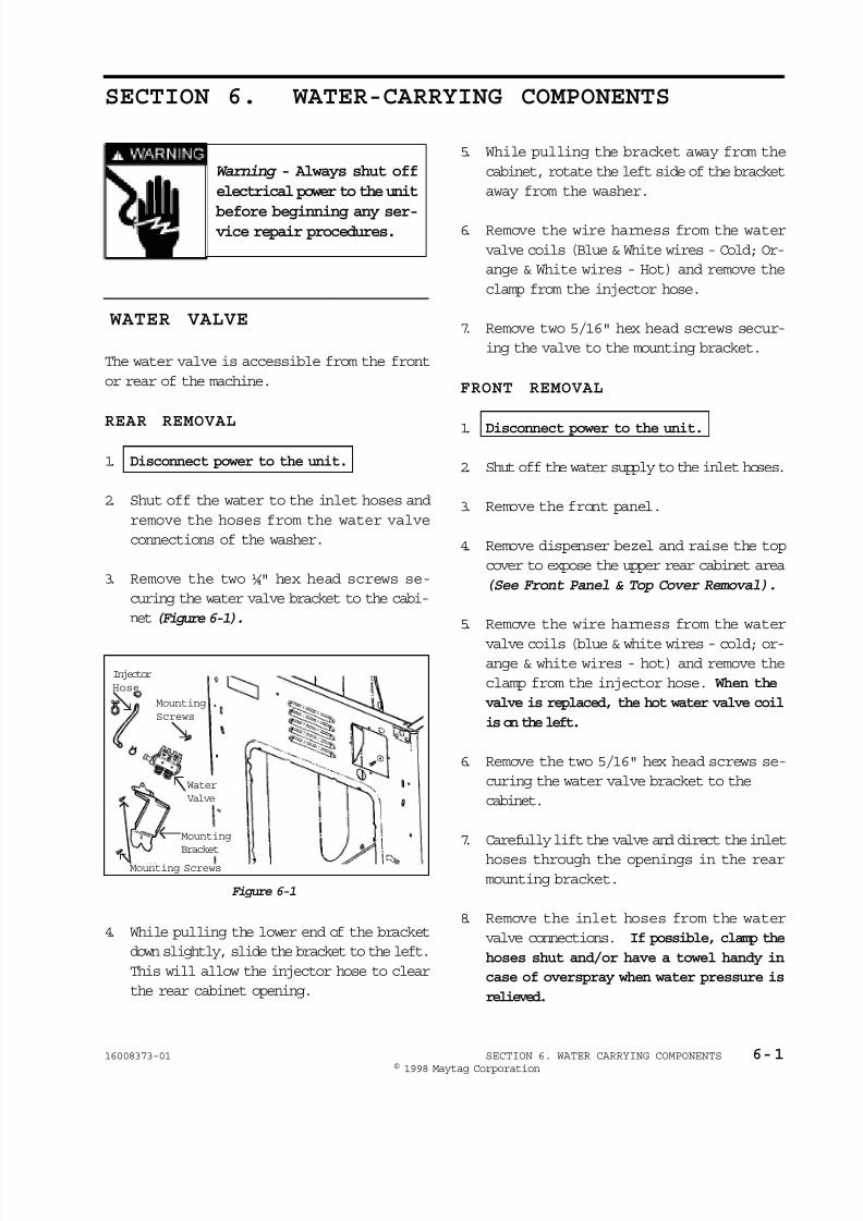
8/3/2019 Maytag MAH3000AWW Service Manual
http://slidepdf.com/reader/full/maytag-mah3000aww-service-manual 59/157
© 1998 Maytag Corporation
16008373-01 SECTION 6. WATER CARRYING COMPONENTS 6-1
SECTION 6. WATER-CARRYING COMPONENTS
Warning - Always shut off
electrical power to the unit
before beginning any ser-vice repair procedures.
5. While pulling the bracket away from the
cabinet, rotate the left side of the bracket
away from the washer.
6. Remove the wire harness from the water
valve coils (Blue & White wires - Cold; Or-
ange & White wires - Hot) and remove the
clamp from the injector hose.
7. Remove two 5/16" hex head screws secur-
ing the valve to the mounting bracket.
FRONT REMOVAL
1. Disconnect power to the unit.
2. Shut off the water supply to the inlet hoses.
3. Remove the front panel.
4. Remove dispenser bezel and raise the top
cover to expose the upper rear cabinet area
(See Front Panel & Top Cover Removal).
5. Remove the wire harness from the water
valve coils (blue & white wires - cold; or-ange & white wires - hot) and remove the
clamp from the injector hose. When the
valve is replaced, the hot water valve coil
is on the left.
6. Remove the two 5/16" hex head screws se-
curing the water valve bracket to the
cabinet.
7. Carefully lift the valve and direct the inlet
hoses through the openings in the rearmounting bracket.
8. Remove the inlet hoses from the water
valve connections. If possible, clamp the
hoses shut and/or have a towel handy in
case of overspray when water pressure is
relieved.
Mounting
Screws
Injector
Hose
Mounting
Bracket
Mounting Screws
Water
Valve
WATER VALVE
The water valve is accessible from the front
or rear of the machine.
REAR REMOVAL
1. Disconnect power to the unit.
2. Shut off the water to the inlet hoses and
remove the hoses from the water valve
connections of the washer.
3. Remove the two ¼" hex head screws se-
curing the water valve bracket to the cabi-
net(Figure 6-1).
4. While pulling the lower end of the bracket
down slightly, slide the bracket to the left.
This will allow the injector hose to clear
the rear cabinet opening.
Figure 6-1
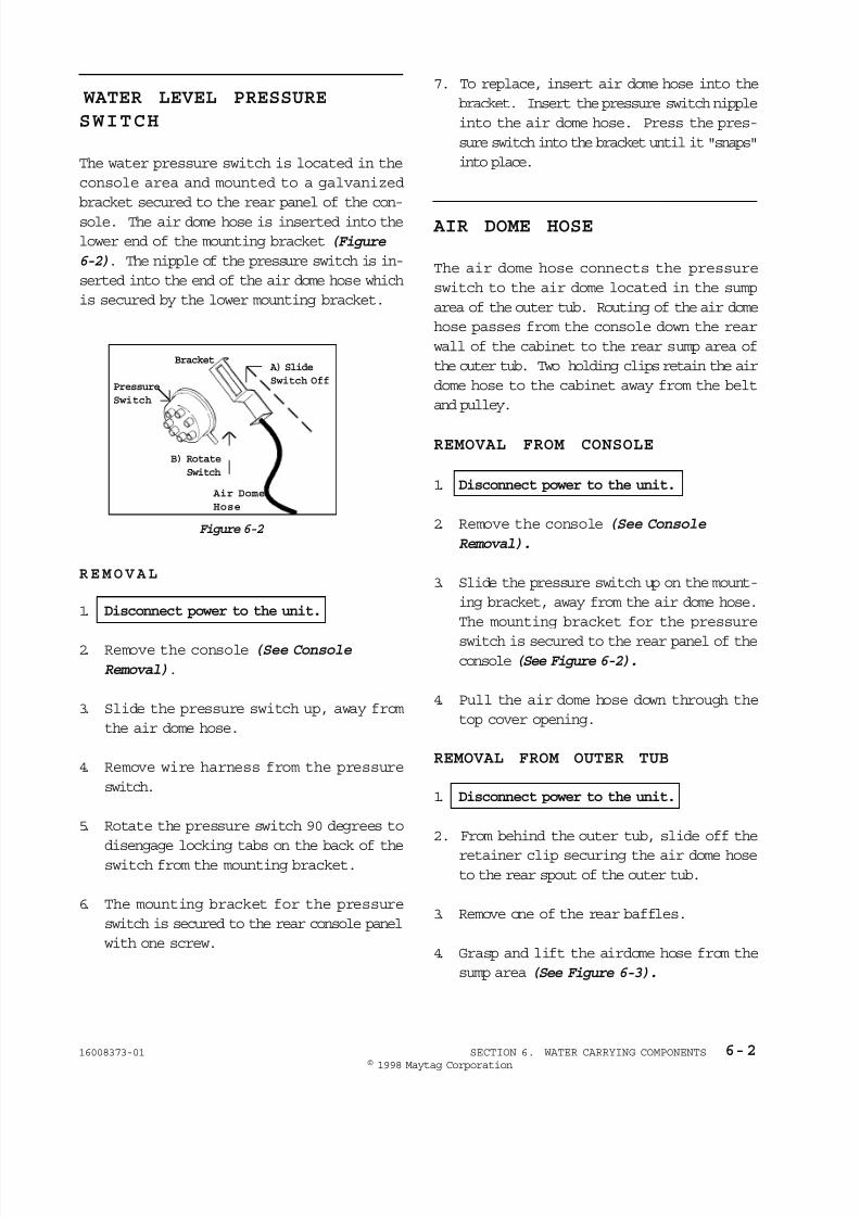
8/3/2019 Maytag MAH3000AWW Service Manual
http://slidepdf.com/reader/full/maytag-mah3000aww-service-manual 60/157
© 1998 Maytag Corporation
16008373-01 SECTION 6. WATER CARRYING COMPONENTS 6-2
AIR DOME HOSE
The air dome hose connects the pressure
switch to the air dome located in the sump
area of the outer tub. Routing of the air dome
hose passes from the console down the rear
wall of the cabinet to the rear sump area of
the outer tub. Two holding clips retain the air
dome hose to the cabinet away from the belt
and pulley.
REMOVAL FROM CONSOLE
1. Disconnect power to the unit.
2. Remove the console (See Console
Removal).
3. Slide the pressure switch up on the mount-
ing bracket, away from the air dome hose.
The mounting bracket for the pressure
switch is secured to the rear panel of theconsole (See Figure 6-2).
4. Pull the air dome hose down through the
top cover opening.
REMOVAL FROM OUTER TUB
1. Disconnect power to the unit.
2. From behind the outer tub, slide off the
retainer clip securing the air dome hoseto the rear spout of the outer tub.
3. Remove one of the rear baffles.
4. Grasp and lift the airdome hose from the
sump area (See Figure 6-3).
REMOVAL
1. Disconnect power to the unit.
2. Remove the console (See Console
Removal).
3. Slide the pressure switch up, away from
the air dome hose.
4. Remove wire harness from the pressure
switch.
5. Rotate the pressure switch 90 degrees to
disengage locking tabs on the back of the
switch from the mounting bracket.
6. The mounting bracket for the pressure
switch is secured to the rear console panel
with one screw.
7. To replace, insert air dome hose into the
bracket. Insert the pressure switch nipple
into the air dome hose. Press the pres-
sure switch into the bracket until it "snaps"
into place.
WATER LEVEL PRESSURE
SWITCH
The water pressure switch is located in the
console area and mounted to a galvanized
bracket secured to the rear panel of the con-
sole. The air dome hose is inserted into the
lower end of the mounting bracket (Figure
6-2). The nipple of the pressure switch is in-
serted into the end of the air dome hose which
is secured by the lower mounting bracket.
Figure 6-2
Pressure
Switch
BracketA) Slide
Switch Off
B) Rotate
Switch
Air Dome
Hose

8/3/2019 Maytag MAH3000AWW Service Manual
http://slidepdf.com/reader/full/maytag-mah3000aww-service-manual 61/157
© 1998 Maytag Corporation
16008373-01 SECTION 6. WATER CARRYING COMPONENTS 6-3
5. Pull the air dome and hose out through the
sump opening in the spin basket (Figure
6-3).
REPLACEMENT/ROUTING
1. Thread the narrow end of the hose through
the air dome outlet in the rear of the outer
tub (Figure 6-3). Apply alcohol to lubri-
cate the hose to ease insertion into the
outer tub air dome outlet.
NOTE: Using soap and water may lead to a
potential leak.
2. Secure the retainer clip on the outside
ridge of the air dome hose.
3. Push the bent end of the air dome down
into the sump area, below the spin basket,
making sure the flat rubber tab on the air
dome is down inside the drain sump
opening.
4. The air dome hose is retained to the
rear wall of the cabinet with two clips.
NOTE: A silver indicator mark is located
approximately 20 inches away from the air
dome. The indicator mark must be located
under the lower clip to allow the correct
amount of slack in the hose.
DISPENSER ASSEMBLY
The dispenser assembly is located in the left
hand side of the top cover. Three bays dis-
pense the fabric softener, bleach and deter-
gent into the wash load. A double wax motor
mechanism directs the flow of water into each
specific bay when required for disbursementinto the wash load. When a specific fluid is
required, the water is directed into that bay.
As water fills the bay, the fluid level rises.
When the fluid reaches a specific height, it is
siphoned out into the dispenser injector hose
to the wash load.
Spin Basket
Sump
Opening
Exposed
Rear
Baffle
RemovedAir Dome
Outlet
Figure 6-4
Figure 6-3
5. Remove all slack in the hose between the
upper and lower clips holding the air dome
hose. This reduces the potential for noise.
6. Route the air dome hose into the center
rear hole in the top cover. Route toward
the pressure switch and secure the hose
to the pressure switch.
Siphon Cap
Siphon Cup
Dispenser Bottom
Wax Motors
Linkage
Rotary
Nozzle
Dispenser
Top
REMOVAL
1. Disconnect power to the unit.
2. Remove the siphon cup and cap.
3. Remove the four screws securing the dis-
penser bezel and assembly to the top
cover.

8/3/2019 Maytag MAH3000AWW Service Manual
http://slidepdf.com/reader/full/maytag-mah3000aww-service-manual 62/157
© 1998 Maytag Corporation
16008373-01 SECTION 6. WATER CARRYING COMPONENTS 6-4
FRONT WATER FLUME INJECTOR
REMOVAL
1. Disconnect power to the unit.
2. Remove the front panel and raise the top
cover to expose the upper front
cabinet area (See Front Panel & Top Cover
Removal).
3. Remove the front shroud assembly (See
Front Shroud Assembly Removal).
4. Remove the outer tub cover (See Outer
Tub Cover Removal).
PUMP ASSEMBLY
The pump assembly is mounted to the right
rear area of the base.
REMOVAL
1. Disconnect power to the unit.
2. Spread a towel below the drain hoses prior
to loosening the hose clamps. This will
catch any residual water left in the hoses
and sump area.
3. Remove the hose clamps and hoses fromthe pump.
4. Remove the wiring harness from the pump
motor terminals.
5. Rotate the pump assembly in a counter-
clockwise direction. The support legs of
the pump are slotted to engage in keyed
slots in the base. Reverse the steps to re-
mount the pump.
As water is filling the dispenser assembly,water is also diverted to a hose leading to the
front of the outer tub.
As the water enters
the top of the outer
tub through the hose,
it passes through a
water flume. The
flume directs the wa-
ter toward the front of
the tub to saturate the
clothes load.
Figure 6-5
4. Remove the front panel and top cover (See
Front Panel & Top Cover Removal).
5. Disconnect the hoses attached to the dis-
penser assembly.
6. While lifting, rotate the dispenser assem-
bly 90 degrees in a counterclockwise
direction.
NOTE: The two tabs on the side wall of the
dispenser bottom may break off if the above
procedure is not followed properly.
5. Remove the hose clamp and injector hose
from the spout on the front upper area of
the outer tub.
6. In order to provide sufficient space to re-
move the injector, place a 5/8" - 3/4" wedge
between the spinner and the outer tub.
7. Pinch the two tabs exposed on the outer
edge of the outer tub spout and press the
injector into the tub. Reverse the previ-
ous steps to replace the injector.

8/3/2019 Maytag MAH3000AWW Service Manual
http://slidepdf.com/reader/full/maytag-mah3000aww-service-manual 63/157
© 1998 Maytag Corporation
16008373-01 SECTION 6. WATER CARRYING COMPONENTS 6-5
CLEANING THE PUMP
The pump assembly can also be disassembled
without removing the hoses from the pump
(See Figure 6-6).
1. Depress the locking tab on the face of the
pump housing.
2. Rotate the block portion of the pump con-
taining the motor windings toward the
front of the washer. This will disengage
the locking tabs of the pump housing from
the pump face.
3. Carefully remove the pump body away
from the housing. The drain impeller is
exposed for cleaning.
Pump Accessory Kit
1. Disconnect power to the unit.
2. Disconnect the drain hose from the exist-
ing pump in the washer.
3. Attach the accessory connector to the
pump drain outlet and secure with the
clamp found in the kit.
4. Position the second pump near the first
pump and connect the accessory connec-
tor to the sump intake of the second pump.
Secure with the clamp in the kit.
5. Connect the drain hose to the drain outlet
of the second pump. Secure with a clamp.
6. The second pump assembly is not secured
to the washer's base frame.
7. Installation is complete.
Figure 6-6 Figure 6-7
Figure 6-8

8/3/2019 Maytag MAH3000AWW Service Manual
http://slidepdf.com/reader/full/maytag-mah3000aww-service-manual 64/157
© 1998 Maytag Corporation
16008373-01 SECTION 6. WATER CARRYING COMPONENTS 6-6
Figure 6-9
Drain Hose
Access
Cover
Figure 6-10
Drain HoseClamp
DRAIN HOSE
The drain hose attaches to the pump and is
routed through the lower rear wall of the cabi-
net. The drain hose is protected externally by
a shield.
REMOVAL
1. Disconnect power to the unit.
2. Remove the four ¼" hex head screws se-
curing the access panel to the rear wall of
the cabinet.
3. Remove the ¼" hex head screw securing
the drain hose shield. Remove shield.
4. With access into the machine compart-
ment, spread a towel under the connec-
tion of the drain hose to the pump. Loosen
the clamp and remove the drain hose (Fig-
ure 6-10).
5. Reverse the previous steps for
replacement.

8/3/2019 Maytag MAH3000AWW Service Manual
http://slidepdf.com/reader/full/maytag-mah3000aww-service-manual 65/157
© 1998 Maytag Corporation
16008373-01 SECTION 6. WATER CARRYING COMPONENTS 6-7

8/3/2019 Maytag MAH3000AWW Service Manual
http://slidepdf.com/reader/full/maytag-mah3000aww-service-manual 66/157
© 1998 Maytag Corporation
16008373-01 SECTION 7. OUTER TUB & SPINNER ASSEMBLY 7-1
SECTION 7. OUTER TUB & SPINNER ASSEMBLY
Warning - Always shut off
electrical power to the unit
before beginning any ser-vice repair procedures.
DOOR BOOT
The door boot rubber gasket provides a seal
between the outer tub assembly and the frontshroud. The boot seal is secured to the front
shroud by locking tabs on the boot seal, which
engage with slots in the shroud. Attachment
to the outer tub is by a wire loop stretched
around the perimeter of the opening in the
outer tub cover and secured with a spring.
REMOVAL
1. Disconnect power to the unit.
2. Remove the front panel, top cover and
front shroud (See Front Panel, Top and
Front Shroud Removal).
3. Using one of the two hold down brackets
(See Figure 5-6) or one of the two front
support springs, grasp the hook of the boot
clamp spring. With the other hand, press
the wire loop into the door boot. This will
brake the wire into the door boot and not
allow the wire to slip.
NOTE: Be careful not to bend or crease the
wire loop. If the wire loop becomes bent, the
result will be a potential leak upon replace-
ment of the boot seal onto the outer tub
cover.
4. Pull the boot clamp spring hook towardthe wire loop and disengage the springfrom the wire loop.
5. Carefully remove the wire loop from thelip of the outer tub cover.
NOTE: Note the orientation ribs on the outer
tub cover and the locating notches in the door
boot seal lip.
Figure 7-1
Locking
Tabs Boot
Gasket
Door Shroud
BAFFLES
The baffles in the spin basket distribute and
redistribute the clothes during the tumbling
action of the washer.
REMOVAL
1. Disconnect power to the unit.
2. The three rear baffles within the spin bas-
ket are removed by removing the two
crosshead screws securing each baffle
from inside the spin basket.
3. The three front baffles within the spin bas-
ket are removed by removing the two ¼"
hex head screws from outside of the spin
basket. To gain access, remove the outer
tub cover. The front baffle mounting
screws can now be reached through the
sump area, using a flat ratchet with a ¼"
drive socket.

8/3/2019 Maytag MAH3000AWW Service Manual
http://slidepdf.com/reader/full/maytag-mah3000aww-service-manual 67/157
© 1998 Maytag Corporation
16008373-01 SECTION 7. OUTER TUB & SPINNER ASSEMBLY 7-2
6. Unsnap the locking tabs of the door boot
around the inside perimeter of the door
shroud (Figure 7-1).
REPLACEMENT
1. Align the door boot with the D-shape to-
ward the front, with the flat of the D to-
ward the bottom. Also, locate the large
tab toward the top center of the shroud.
2. Stretch the rear lip of the door boot onto
the tub cover.
3. Move the rear door boot lip along the face
of the tub cover until the locator notches
in the door boot align with the locator ribs
in the tub cover. Check alignment of the
six rib marks and reposition if necessary.
This is necessary in order to have the lock-
ing tabs on the inside perimeter of the door
boot align with the corresponding tabs on
the front shroud.
4. Carefully loop the wire loop with spring
around the lip of the outer tub cover and
place the spring at the 11:00 o'clock posi-
tion, just left of the top rib of the outer tub
cover. Hook the end of the spring over the
nearest tub cover clip to hold the spring
and wire in position for final hookup to the
other end of the wire loop.
5. Using either the hold down bracket or the
outer tub spring, grasp the hook end of
the spring and apply pressure on the
clamp wire into the door boot.
6. Pull the spring hook toward the wire loopto engage the spring with the wire loop.
NOTE: Be careful not to bend or crease the
wire loop. If the wire loop becomes bent, the
result will be a potential leak upon replace-
ment of the boot seal onto the outer tub
cover.
OUTER TUB COVER
The outer tub cover has a gasket seal em-
bedded in the outer flange of the cover to
seal the cover to the outer tub. The cover is
secured to the outer tub by means of twelve
(12) locking clips evenly spaced around the
perimeter of the cover. When the outer tubcover is removed, access to the sump area
and the front injector flume is possible.
REMOVAL
1. Disconnect power to the unit.
2. Remove the front panel, top cover and
front shroud (See Front Panel, Top
Cover, and Front Shroud Removal).
3. Using a flathead screwdriver, slide un-der the clip and pry to remove. Removethe remaining clips from the outer tub
cover.
4. Remove the cover from the outer tub.This exposes the sump area on the floorof the outer tub and the water injectorflume on top of the outer tub.
7. Reposition the front shroud on the front
of the washer and secure (See Front
Shroud).
8. Pull the front edge of the door boot and
locate the widest locking tabs, located
at the 12, 4 & 8 o'clock positions. Insert
the locking tabs into the large interlock-
ing slots in the shroud. (Spraying the
surface with window cleaner or a soap
solution aids reinsertion of the tabs into
the plastic front shroud.) Press the thick
rubber section of the door boot into the
groove in the shroud so the locking tabs
engage in the slots.
9. Press the remaining locking tabs into the
perimeter of the shroud.

8/3/2019 Maytag MAH3000AWW Service Manual
http://slidepdf.com/reader/full/maytag-mah3000aww-service-manual 68/157
© 1998 Maytag Corporation
16008373-01 SECTION 7. OUTER TUB & SPINNER ASSEMBLY 7-3
SPIN BASKET ASSEMBLY
w/BALANCE RING
The balance ring is securely fastened to the
spin basket and cannot be obtained as a sepa-
rate repair part. To obtain, order complete
spin basket assembly. The balance ring is
filled with a calcium chloride solution and
baffles.
Figure 7-3
Figure 7-4
Figure 7-2
REMOVAL
1. Disconnect power to the unit.
2. Remove the front panel, top cover, front
shroud, outer tub cover and rear baffles
(See Front Panel, Top cover, Front Shroud,
Outer Tub Cover and Rear Baffle
Removal).
3. To separate the spinner tub support from
the spinner, remove the three rear baffles
within the spin basket by removing the two
screws securing each baffle (See Baffle
Removal).
4. Remove the three locking type nuts (½"
socket) securing the spin basket to the spi-
der assembly (Figure 7-5).
within the ring allow the fluid to disperse
within the ring evenly. By rotating the spin
basket, you can hear the fluid dispersing
within the baffles of the balance ring. This
sound is normal.
The spin basket is mounted to the spinner sup-
port by means of threaded studs on the sup-
port extending through the spin basket and
secured with nuts. The mounting nuts are
concealed under the rear baffles (Figure 7-4).

8/3/2019 Maytag MAH3000AWW Service Manual
http://slidepdf.com/reader/full/maytag-mah3000aww-service-manual 69/157
© 1998 Maytag Corporation
16008373-01 SECTION 7. OUTER TUB & SPINNER ASSEMBLY 7-4
DRIVE PULLEY
The drive pulley can be accessed via the rear
access panel of the washer. The pulley is se-
cured to the shaft of the spider assembly by a
bolt. The direction of pulley rotation controls
the spin action of the spin basket.
1. Disconnect power to the unit.
2. Remove the rear access panel from the
washer to access the pulley area.
3. Remove the bolt and the spider shaft will
be exposed. Carefully slide the pulley off
the spider shaft, using a "rocking/side-to-
side" motion. If the pulley has a snug fit,
use your Spanner Wrench to apply enoughleverage to pry the pulley off the shaft
(Figure 7-6).
Figure 7-6
REPLACEMENT
1. Slide pulley on shaft.
2. Insert new tabbed washer and secure thebolt with a 9/16" socketed ratchet wrench
(30 in. lbs. torque).
NOTE: If the washer is cupped, flip the
washer on the pulley so the cupped portion
extends away from the shaft. Failure to do
so can result in a binding of the spinner sup-
port shaft and seals.
Spinner
Support
Washer
Locking Nut
5. Remove the spin basket by lifting it off the
threaded bolts of the spinner support.
6. When replacing the spin basket onto the
spinner support, replace the washers un-
der the three locking type nuts. Secure
the ½" nuts firmly (18 in. lbs. torque).
Figure 7-5
Profile
Washer

8/3/2019 Maytag MAH3000AWW Service Manual
http://slidepdf.com/reader/full/maytag-mah3000aww-service-manual 70/157
© 1998 Maytag Corporation
16008373-01 SECTION 7. OUTER TUB & SPINNER ASSEMBLY 7-5
SPINNER TUB SUPPORT
The spinner tub support attaches to the spin basket and the shaft of the spider extends through
a seal system to the exterior of the outer tub with a pulley attached to the end of the shaft
(Figure 7-7). This assembly supports the spin basket and transfers the rotation of the drive
pulley directly to the rotation of the spin basket.
NOTE: When the spinner tub support is removed, the shaft seal system should be replaced.
Figure 7-7
Spin
Basket
REMOVAL
1. Disconnect power to the unit.
2. Remove the front panel, top cover, front shroud and outer tub cover (See Front Panel, Top Cover, Front Shroud and Outer Tub Cover Removal).
3. Remove the drive pulley (See Pulley Removal).
4. With the pulley removed, the spin basket with the spider shaft can be pulled from the front
of the outer tub assembly.
5. To separate the spinner tub support from the spinner, remove the three rear baffles within
the spin basket by removing the two screws securing each baffle (See Baffle Removal).
6. Remove the three locking nuts (½" socket) securing the spin basket to the spider assembly.
7. Remove the shaft seal (Figure 7-8).
REPLACEMENT
1. Reverse the previous steps.
2. IMPORTANT: Secure the three locking nuts (½" socket) on the spinner tub support studs
(18 in. lbs. torque).
(See Figure 7-5)
Plastic
Washer Seal
Spacer
Sleeve
Spinner
Support

8/3/2019 Maytag MAH3000AWW Service Manual
http://slidepdf.com/reader/full/maytag-mah3000aww-service-manual 71/157
© 1998 Maytag Corporation
16008373-01 SECTION 7. OUTER TUB & SPINNER ASSEMBLY 7-6
SEAL SYSTEM
A multi-lipped water seal is positioned on the
tub support shaft leading to the outer tub bear-
ing. This prevents water inside the tub from
reaching the bearings. The water seal is ac-
cessed by removing the tub support shaft. Itis comprised of a stainless steel seal face po-
sitioned on the tub support shaft, which mates
with a rubber gasket. Grease on the face of
the rubber gasket provides lubricant for the
steel seal face. The steel seal face provides
the rotating seal surface against the circular
rubber ribs in the face of the rubber seal. This
makes for three rib contacts at various diam-
eters, providing three seals.
REMOVAL
1. Disconnect power to the unit.
2. Remove the spinner tub support with spin-
ner (See Spinner Tub Support Removal).
3. With a flathead screwdriver, pry the seal
carefully off the tub support shaft (Figure
7-8).
4. Reach inside the outer tub bearing area
and remove the rubber seal. Discard both
the steel seal washer and the rubber seal
(Figure 7-9).
5. Position the spacer, replacement rubber
seal and steel seal washer into the outer
tub bearing area.
6. Position the spinner with spinner support
shaft into the outer tub and insert the shaft
through the seal in the rear of the outer
tub until the spinner support shaft seats
into place.
7. Reposition the drive pulley with tabbed
washer onto the spinner support shaft.
Insert the retaining bolt and tighten se-
curely (30 in. lbs. torque). This will draw
the shaft and seals into proper alignment.
Figure 7-9
Figure 7-8

8/3/2019 Maytag MAH3000AWW Service Manual
http://slidepdf.com/reader/full/maytag-mah3000aww-service-manual 72/157
© 1998 Maytag Corporation
16008373-01 SECTION 7. OUTER TUB & SPINNER ASSEMBLY 7-7
Upper
Weight
REMOVAL OF LOWER FRONT WEIGHT
1. Remove the front panel (See Front Panel).
2. Remove the two bolts securing the weightto the outer tub assembly. Use a 9/16"
socket (Figure 7-12).
3. Lower the front weight and guard against
hitting the motor control microprocessor
board mounted to the base assembly.
REMOVAL OF UPPER WEIGHT
1. Disconnect power to the unit.
2. Lift top cover (See Top Cover).
3. Remove the two ½" counter balance bolts
securing the weight to the top of the outertub assembly.
NOTE: The bolts screw into two nuts below
the weight, under the tub mounting pad (Fig-
ure 7-11).
OUTER TUB ASSEMBLY
The outer tub assembly is suspended from two
springs positioned toward the upper front of
the cabinet and supported in the rear by two
struts which are secured to the base frame.
Two counter weights are mounted to the outertub from above and below the tub. The alu-
minum bearing housing retains both inner and
outer bearings for the spinner tub support
shafts.
BEARINGS
The bearings are not repairable or replaceable.
Replacement of the complete outer tub as-
sembly is required.
COUNTER WEIGHTS
Two counter weights are secured to the outer
tub assembly. One is secured to the top of
the tub assembly and the other is secured to
the bottom of the tub assembly.
Figure 7-11
Figure 7-10
Front
Water
Flume
Displacement
Switch
Figure 7-12
Counter
Balance
Bolt
Upper
Weight
Nut
Counter Balance
Bolt
Front
Weight
Strap

8/3/2019 Maytag MAH3000AWW Service Manual
http://slidepdf.com/reader/full/maytag-mah3000aww-service-manual 73/157
© 1998 Maytag Corporation
16008373-01 SECTION 7. OUTER TUB & SPINNER ASSEMBLY 7-8
STRUT ASSEMBLY
Two struts are mounted to the base and in-
serted into rubber isolators in the rear of the
outer tub assembly. The struts provide sus-
pension support to the outer tub assembly.
REMOVAL
1. Disconnect power to the unit.
2. Remove the front panel, top cover and
front shroud (See Front Panel, Top Cover
and Front Shroud Removal).
3. Disconnect dispenser hoses and injector
hose connections to the outer tub.
4. Lean the cabinet forward to access the two
locking nuts that secure the struts to the
bottom of the base frame assembly. Use
an 8mm or ½" socket. Remove the lock-
ing nuts and lower strut washers.
5. With the washer standing upright, roll the
washer forward and off the struts, which
mount into the rubber isolators inserted
into the rear of the outer tub.
6. To Reinstall: Reverse the previous steps.
Isolator
Locking NutLower Strut Washer
Rear Strut
Push Rod
Isolator
Strut
Figure 7-13
Strut Displacement Switch
1. Disconnect power to the unit.
2. Remove the rear access panel for imme-diate access or remove the front panel.
3. Remove the wires to the switch.
4. Release the small locking tab on top of the
switch and rotate the switch to disengage
the switch from the strut.
5. To Reinstall: Reverse the aforementioned
steps.
INERTIAL UNBALANCE SWITCH
The purpose of the switch is to monitor the
lateral horizontal movement of the outer tub
during spin (above 500 RPM), versus the ver-
tical movement. When a severe amount of
motion is detected, the machine control will
implement a reduction in speed or start a re-
distribution of the clothes load. This is doneby gradually stopping the motor. After the
motor stops, the tumbler will alternately
tumble, first in one direction then another. Af-
ter a brief time, the machine will again work
up to a full spin. Should the machine detect
another unbalance, the control will implement
another redistribution of the load.

8/3/2019 Maytag MAH3000AWW Service Manual
http://slidepdf.com/reader/full/maytag-mah3000aww-service-manual 74/157
© 1998 Maytag Corporation
16008373-01 SECTION 7. OUTER TUB & SPINNER ASSEMBLY 7-9
REMOVAL
1. Disconnect power to the unit.
2. Remove the front panel and lift the top
cover (See Front Panel & Top Cover
Removal).
3. The switch is located on the upper right
hand side of the outer tub assembly (Fig-
ure 7-14).
4. Remove the two screws securing the
switch to the outer tub assembly.
Figure 7-14
REMOVAL
1. Disconnect power to the unit.
2. Remove the front panel and lift the top
cover (See Front Panel & Top Cover Re-
moval).
3. The switch is located on the upper right
hand side of the outer tub assembly, di-
rectly behind the right upper front suspen-
sion spring(Figure 7-15).
4. Remove the screw and flat washer secur-
ing the switch in place.
5. Using a flathead screwdriver, pry the
switch body from the outer tub assembly.
TUB DISPLACEMENT SWITCH
The displacement switch is located on the
right hand side of the outer tub assembly, be-
low the upper weight. The location of the
switch on the outer tub will activate the switch
whenever the outer tub assembly makes con-
tact with the wall of the cabinet. Should con-
tact with the cabinet occur before the machine
reaches 500 rpm, the machine control is
alerted and will reduce speed to implement aredistribution program.
Outer Tub
Switch
Figure 7-15

8/3/2019 Maytag MAH3000AWW Service Manual
http://slidepdf.com/reader/full/maytag-mah3000aww-service-manual 75/157
© 1998 Maytag Corporation
16008373-01 SECTION 7. OUTER TUB & SPINNER ASSEMBLY 7-10

8/3/2019 Maytag MAH3000AWW Service Manual
http://slidepdf.com/reader/full/maytag-mah3000aww-service-manual 76/157
© 1998 Maytag Corporation
1 6008373-0 1 SECTION 8. MOTOR DRIVE SYSTEM 8 - 18 - 18 - 18 - 18 - 1
SECTION 8. MOTOR DRIVE SYSTEMSECTION 8. MOTOR DRIVE SYSTEMSECTION 8. MOTOR DRIVE SYSTEMSECTION 8. MOTOR DRIVE SYSTEMSECTION 8. MOTOR DRIVE SYSTEM
Warning Warning Warning Warning Warning - Always shut off- Always shut off- Always shut off- Always shut off- Always shut off
electrical power to theelectrical power to theelectrical power to theelectrical power to theelectrical power to the
unit before beginning anyunit before beginning anyunit before beginning anyunit before beginning anyunit before beginning anyservice procedures.service procedures.service procedures.service procedures.service procedures.
DRIVE BELTDRIVE BELTDRIVE BELTDRIVE BELTDRIVE BELT
The drive belt has six (6) ribs which mate
with the face of the motor pulley. The belt
encircles the motor pulley and the drive
pulley of the spinner.
R E M O V A LR E M O V A LR E M O V A LR E M O V A LR E M O V A L
1. Disconnect power to the unit.Disconnect power to the unit.Disconnect power to the unit.Disconnect power to the unit.Disconnect power to the unit.
2 . Roll the belt off the drive pulley and re-
move from the motor pulley.
A D J U S T M E N TA D J U S T M E N TA D J U S T M E N TA D J U S T M E N TA D J U S T M E N T
Check belt tension. If loose, remove the belt,
loosen the belt adjustment wheel bolt and
rotate the wheel one notch in a clockwise
rotation. Check belt tension again. The belt
should experience no more than 1" deflectionwhen depressed toward the inside
(Figure 8-1).(Figure 8-1).(Figure 8-1).(Figure 8-1).(Figure 8-1).
The motor drive system tear-down procedure
covers all components related to the drive
system, such as the drive motor, drive belt,
motor control, machine control and acceler-
ometer switch.
DRIVE MOTORDRIVE MOTORDRIVE MOTORDRIVE MOTORDRIVE MOTOR
The drive motor is hinged into the left bottom
area of the outer tub and secured to the outer
tub by the bolt on the belt adjustment wheel.
A slot in the mounting bracket of the outer
tub allows the motor to pivot and allows
adjustment of the drive belt tension.
R E M O V A LR E M O V A LR E M O V A LR E M O V A LR E M O V A L
1 . Disconnect power to the unit.Disconnect power to the unit.Disconnect power to the unit.Disconnect power to the unit.Disconnect power to the unit.
2 . Remove the front panel, rear access panel
and the front weight (See Front Panel &(See Front Panel &(See Front Panel &(See Front Panel &(See Front Panel &
Rear Access Removal).Rear Access Removal).Rear Access Removal).Rear Access Removal).Rear Access Removal).
3 . From the rear, locate the belt adjustment
wheel and note the adjustment number
aligned with the rib of the outer tub. This
will help later when the belt adjustmentwheel is placed back onto the outer tub
and the belt is remounted on the motor
and drive pulley. Remove the bolt secur-
ing the belt adjustment wheel
(Figure 8-2).(Figure 8-2).(Figure 8-2).(Figure 8-2).(Figure 8-2).
Figure 8-1 Figure 8-1 Figure 8-1 Figure 8-1 Figure 8-1

8/3/2019 Maytag MAH3000AWW Service Manual
http://slidepdf.com/reader/full/maytag-mah3000aww-service-manual 77/157
© 1998 Maytag Corporation
16 008373-0 1 SECTION 8. MOTOR DRIVE SYSYTEM 8 - 28 - 28 - 28 - 28 - 2
4 . Lift the motor slightly to disengage the belt
from the motor pulley. Place motor on the
base frame.
5 . From the front, remove the wire harnesses
from the back of the motor.
6 . Grasp the motor and slide it carefully from
the pivot hang holes in the outer tub.
R E P L A C E M E N TR E P L A C E M E N TR E P L A C E M E N TR E P L A C E M E N TR E P L A C E M E N T
1 . Reverse the previous procedures to re-
mount the motor.
NOTE:NOTE:NOTE:NOTE:NOTE: Prior to hanging the motor, recon-Prior to hanging the motor, recon-Prior to hanging the motor, recon-Prior to hanging the motor, recon-Prior to hanging the motor, recon-
nect motor wire harnesses and ground wire.nect motor wire harnesses and ground wire.nect motor wire harnesses and ground wire.nect motor wire harnesses and ground wire.nect motor wire harnesses and ground wire.
2 . Prior to hanging the motor on the outer
tub, check the positioning of the rubber
motor mounts.
3 . Check belt tension. If loose, loosen the belt
adjustment wheel bolt and rotate the
wheel one notch in a clockwise rotation.
Check belt tension again. The belt shouldexperience no more than a 1" deflection
when depressed to the inside.
Figure 8-2 Figure 8-2 Figure 8-2 Figure 8-2 Figure 8-2
MACHINE CONTROLMACHINE CONTROLMACHINE CONTROLMACHINE CONTROLMACHINE CONTROL
The machine control is located in the control
console and is secured to the rear cover.
R E M O V A LR E M O V A LR E M O V A LR E M O V A LR E M O V A L
1 . Disconnect power to the unit.Disconnect power to the unit.Disconnect power to the unit.Disconnect power to the unit.Disconnect power to the unit.
2 . Remove the control console (See Control (See Control (See Control (See Control (See Control
Console Removal) .Console Removal) .Console Removal) .Console Removal) .Console Removal) .
3 . Remove the wiring from the machine con-
trol, paying close attention to the wire har-
ness hookup to the control board.
4. Remove the two 5/16" nuts securing the
board to the rear console panel.
5 . Reverse the previous procedures to re-
mount the board.
Figure 8-3 Figure 8-3 Figure 8-3 Figure 8-3 Figure 8-3

8/3/2019 Maytag MAH3000AWW Service Manual
http://slidepdf.com/reader/full/maytag-mah3000aww-service-manual 78/157
© 1998 Maytag Corporation
1 6008373-0 1 SECTION 8. MOTOR DRIVE SYSTEM 8 - 38 - 38 - 38 - 38 - 3
MOTOR CONTROLMOTOR CONTROLMOTOR CONTROLMOTOR CONTROLMOTOR CONTROL
The motor control is located behind the front
panel in the lower right hand side of the
cabinet. The assembly comprises of the
circuit board, control cover, mounting plate
and motor wire harness.
R E M O V A LR E M O V A LR E M O V A LR E M O V A LR E M O V A L
1 . Disconnect power to the unit.Disconnect power to the unit.Disconnect power to the unit.Disconnect power to the unit.Disconnect power to the unit.
2 . Remove the front panel ( See Front Panel See Front Panel See Front Panel See Front Panel See Front Panel
Remova l Remova l Remova l Remova l Remova l ) .
3 . Remove the shield/cover from the motor
control board by depressing the locking
tab found along the lower left side of the
motor control base plate.
4. Remove the wire harness leading to the
control console (Figure 8-4).(Figure 8-4).(Figure 8-4).(Figure 8-4).(Figure 8-4).
5 . Remove the wire harness from the motor.
6 . Remove two mounting screws in front of
the motor securing the assembly to the
base. A rear locating tab on the motor
control base engages with a slot in thebase frame.
7 . To replace, reverse the previous steps.
Figure 8-4Figure 8-4Figure 8-4Figure 8-4Figure 8-4

8/3/2019 Maytag MAH3000AWW Service Manual
http://slidepdf.com/reader/full/maytag-mah3000aww-service-manual 79/157
© 1998 Maytag Corporation
16 008373-0 1 SECTION 8. MOTOR DRIVE SYSYTEM 8 - 48 - 48 - 48 - 48 - 4

8/3/2019 Maytag MAH3000AWW Service Manual
http://slidepdf.com/reader/full/maytag-mah3000aww-service-manual 80/157
© 1998 Maytag Corporation
1 6008373-0 1 SECT ION 9 . ELECTRICAL SCHEMATICS 9 - 19 - 19 - 19 - 19 - 1
SECTION 9. ELECTRICAL SCHEMATICS & TIMERSECTION 9. ELECTRICAL SCHEMATICS & TIMERSECTION 9. ELECTRICAL SCHEMATICS & TIMERSECTION 9. ELECTRICAL SCHEMATICS & TIMERSECTION 9. ELECTRICAL SCHEMATICS & TIMER
I N F O R M A T I O NI N F O R M A T I O NI N F O R M A T I O NI N F O R M A T I O NI N F O R M A T I O N
Prior to Series 17

8/3/2019 Maytag MAH3000AWW Service Manual
http://slidepdf.com/reader/full/maytag-mah3000aww-service-manual 81/157
© 1998 Maytag Corporation
16 008373-0 1 SECTION 9. ELECTRICAL SCHEMATICS 9 - 29 - 29 - 29 - 29 - 2
TIMER CHART - Prior to Series 17TIMER CHART - Prior to Series 17TIMER CHART - Prior to Series 17TIMER CHART - Prior to Series 17TIMER CHART - Prior to Series 17

8/3/2019 Maytag MAH3000AWW Service Manual
http://slidepdf.com/reader/full/maytag-mah3000aww-service-manual 82/157
© 1998 Maytag Corporation
1 6008373-0 1 SECT ION 9 . ELECTRICAL SCHEMATICS 9 - 39 - 39 - 39 - 39 - 3
ELECTRICAL SCHEMATIC - Series 17ELECTRICAL SCHEMATIC - Series 17ELECTRICAL SCHEMATIC - Series 17ELECTRICAL SCHEMATIC - Series 17ELECTRICAL SCHEMATIC - Series 17

8/3/2019 Maytag MAH3000AWW Service Manual
http://slidepdf.com/reader/full/maytag-mah3000aww-service-manual 83/157
© 1998 Maytag Corporation
16 008373-0 1 SECTION 9. ELECTRICAL SCHEMATICS 9 - 49 - 49 - 49 - 49 - 4
TIMER CHART - Series 17TIMER CHART - Series 17TIMER CHART - Series 17TIMER CHART - Series 17TIMER CHART - Series 17

8/3/2019 Maytag MAH3000AWW Service Manual
http://slidepdf.com/reader/full/maytag-mah3000aww-service-manual 84/157
© 1998 Maytag Corporation
1 6008373-0 1 SECT ION 9 . ELECTRICAL SCHEMATICS 9 - 59 - 59 - 59 - 59 - 5
ELECTRICAL SCHEMATIC - Series 18ELECTRICAL SCHEMATIC - Series 18ELECTRICAL SCHEMATIC - Series 18ELECTRICAL SCHEMATIC - Series 18ELECTRICAL SCHEMATIC - Series 18

8/3/2019 Maytag MAH3000AWW Service Manual
http://slidepdf.com/reader/full/maytag-mah3000aww-service-manual 85/157
© 1998 Maytag Corporation
16 008373-0 1 SECTION 9. ELECTRICAL SCHEMATICS 9 - 69 - 69 - 69 - 69 - 6
TIMER CHART - Series 18TIMER CHART - Series 18TIMER CHART - Series 18TIMER CHART - Series 18TIMER CHART - Series 18

8/3/2019 Maytag MAH3000AWW Service Manual
http://slidepdf.com/reader/full/maytag-mah3000aww-service-manual 86/157
© 1998 Maytag Corporation
1 6008373-0 1 SECT ION 9 . ELECTRICAL SCHEMATICS 9 - 79 - 79 - 79 - 79 - 7
ELECTRICAL SCHEMATIC - Series 19ELECTRICAL SCHEMATIC - Series 19ELECTRICAL SCHEMATIC - Series 19ELECTRICAL SCHEMATIC - Series 19ELECTRICAL SCHEMATIC - Series 19

8/3/2019 Maytag MAH3000AWW Service Manual
http://slidepdf.com/reader/full/maytag-mah3000aww-service-manual 87/157
© 1998 Maytag Corporation
16 008373-0 1 SECTION 9. ELECTRICAL SCHEMATICS 9 - 89 - 89 - 89 - 89 - 8
N O T E SN O T E SN O T E SN O T E SN O T E S :::::

8/3/2019 Maytag MAH3000AWW Service Manual
http://slidepdf.com/reader/full/maytag-mah3000aww-service-manual 88/157
©2000 Maytag Appliances Sales Company
16010199 (16008373-03)
Revised 7/00
1
INTRODUCTION
Attached is supplement three (16008373-03) for service manual 16008373, which
replaces supplement two (16008373-02). This Maytag Washer Service Manual
supplement covers Models MAH4000 & MAH5500A. We suggest you file this with your
16008373 Manual for reference.
Models covered in this manual supplement:
MAH4000 MAH5500A
CONTENTS
SECTION 1. MAH4000/MAH5500A CONTROL FACIA ........................................ 1
SECTION 2. SPECIFICATIONS ............................................................................. 2
SECTION 3. BASIC MACHINE OPERATION ........................................................ 3
SECTION 4. WASHER CONTROLS OVERVIEW.................................................. 3
SECTION 5. CYCLE REVIEW ................................................................................ 4
Stain Cycle........................................................................................ 4
Cycle Times ...................................................................................... 6
SECTION 6. GENERAL COMPONENT - EXPLODED VIEW ................................ 7
SECTION 7. ELECTRICAL INFORMATION .......................................................... 8
SECTION 8. WATER CARRYING COMPONENTS ............................................... 9
WATER VALVE.................................................................................. 9
DISPENSER ASSEMBLY................................................................ 9
RECIRCULATION PUMP .................................................................. 10
DETERGENT HOSE .......................................................................... 11
SECTION 9. WIRING INFORMATION .................................................................. 14
For additional information on material covered in this manual, including safety issues,
contact:
Maytag Appliances Sales Company
240 Edwards Street, S.E.
Cleveland, TN 37311
Phone: 423-472-3333

8/3/2019 Maytag MAH3000AWW Service Manual
http://slidepdf.com/reader/full/maytag-mah3000aww-service-manual 89/157
©2000 Maytag Appliances Sales Company
16010199 (16008373-03)
Revised 7/00
2
(The following information is supplemental to the information found in the basic
manual part number 16008373.)
SECTION 1. MAH4000/MAH5500A CONTROL FACIA
YTICAPAC teeFcibuC1.3
LACIRTCELE.ylppuslacirtceledesufrorekaerbtiucricpma51seriuqeR;zH06,stloV021
.teltuodeziralopdnadednuorgylreporpaotdetcennocebtsumdrocrewoP
ROTOM.draoblortnocrotomrossecorporcimaybdellortnocrotoMecnatculeRdehctiwS
.1ot41)MPRrennipSotrotoM(oitaRyelluProtoM
EGASUREWOP
sttaW071-elbmuThsaWgniruD:tupnIrotoMsttaW591-elbmuTesniRgniruD
sttaW008-nipSpoT).nipsnisehtolconhtiwnekatsgnidaeregattaW(
DEEPSRELBMUT
MPR15-74elbmuThsaWMPR15-74elbmuTesniR
(MPR008nipSdeepShgiH + nipsmumitponopudesabMPR05)ecnamrofrep
EGASURETAW
esohtelnita)mc /gk44.8-60.1(.I.S.P021-02ebdluohserusserpretaWsehtolchtiwseirav,snollag52yletamixorppasiegasuretawlatoT.noitcennocmaesraerehtraenderusaem,sehtolconhtiwteksabnipsehtnillifretaW.daol
teksabnipsehtfosehcni4-3LEVELHSAWsehcni5-4LEVELESNIR
SHTGNELESOH.evlavretawotdehcattadnasrehsawtelnihtiwsesohtelnitoofruoF
.epipdnatsniard"63etadommoccalliwdnapmupotdehcattaesohniarD
SNOISNEMID 72xW)mc85.86("72:snoisnemiDtenibaC 2 /1 H)mc44.19("63xD)mc58.96("
).xorppA(THGIEW .xorppA).gk19(.bl002detarC.xorppA).gk68(.bl091denotracnU
TLOB&WERCSSEUQROT
(.sbl.ni7thgieWretnuoC,tloB + ).sbl.ni3(.sbl.ni03yelluPnipS,tloB + ).sbl.ni3(.sbl.ni09retsujdAtleB,tloB + ).sbl.ni01(.sbl.ni52elffaBtnorF,wercS + ).sbl.ni3(.sbl.ni5.81elffaBraeR,wercS + ).sbl.ni3
.sbl.ni+51sesoH,pmalC(.sbl.ni81troppuSrennipS,stuN + ).sbl.ni3(.sbl.ni7sturtsnoisnepsuS,stuN + ).sbl.ni3
SECTION 2. SPECIFICATIONS

8/3/2019 Maytag MAH3000AWW Service Manual
http://slidepdf.com/reader/full/maytag-mah3000aww-service-manual 90/157
©2000 Maytag Appliances Sales Company
16010199 (16008373-03)
Revised 7/00
3
SECTION 3. BASIC MACHINE OPERATION
The model MAH4000 and MAH5500A are similar to the MAH3000 washer, with the exception
being the MAH4000 and MAH5500A have a recirculation pump in series between the outer
tub outlet and the drain pump. When the water pressure switch becomes satisfied (Series 11
and later on the MAH4000 and all the MAH5500A), power is then applied to the recirculation
pump. The recirculation pump draws water from the bottom of the outer tub and circulates the
water up through the detergent hose, then into the top of the outer tub. By doing this, the
washer is able to provide a more even distribution of detergent throughout the wash load.
The software of the MAH4000 and MAH5500A models is slightly different than the software
used in the MAH3000 washer. Fabric Selections on the control console were changed from
Cotton/Sturdy to Whites, Easy Care/Perm Press to Colors, Delicates remained the same.
Series 10 of the MAH4000 washer allowed the recirculating pump to be directly controlled bythe timer. (Figure 4-1)
SECTION 4. WASHER CONTROLS OVERVIEW
Series 11 & Later
Figure 4-2
Figure 4-1
Series 10(MAH4000 only)
(MAH4000 & MAH5500A)

8/3/2019 Maytag MAH3000AWW Service Manual
http://slidepdf.com/reader/full/maytag-mah3000aww-service-manual 91/157
©2000 Maytag Appliances Sales Company
16010199 (16008373-03)
Revised 7/00
4
A new Stain Cycle and revised tumble patterns were introduced and will be described
in the following pages.
At series 11 the timer was changed, wire harness revised and the schematic was
changed. The timer cams were changed in the timer, the wire harness changed to pull
wires out of the timer connector and the pump is now in series with the pressure
switch, also an extra wire was jumpered across the pressure switch. Now the recircu-
lating pump is controlled through the pressure switch (Figure 4-2). This was done to
force the washer to fill with water prior to starting the recirculation pump.
SECTION 5. CYCLE REVIEW
Cycles on the Fabrics switch now list the cycles according to how clothes are
sorted. This simiplifies how to select the cycles in doing the wash. A new
Stain Cycle was added to the Option Switch which adds cycle wash time, vari-
ous tumble patterns and an additional rinse with longer tumble times during the
rinse. (See Figure 5-1)
Figure 5-1

8/3/2019 Maytag MAH3000AWW Service Manual
http://slidepdf.com/reader/full/maytag-mah3000aww-service-manual 92/157
©2000 Maytag Appliances Sales Company
16010199 (16008373-03)
Revised 7/00
5
Notes:
1. The main wash times listed include 2 minutes of bleach fill and tumble time.
2. The total cycle times are approximate and will vary based on water fill times, due to
types of clothing loads and the time for the door lock system to retract at the end of
the cycle.
3. The main wash time is affected significantly if the machine control detects an exces-
sive amount of suds via a loss of motor torque. The washer will go into a suds
reduction routine, consisting of a series of additional rinse and partial drain cycles to
reduce the suds present. (See Troubleshooting & Diagnosis - Clothes Wet at End
of Spin)
nrettaPelbmuT /gnilbmutsdnocesforebmuN-
.selbmutneewtebesuapfosdnocesforebmuN
ydrutS/nottoC
/eraCysaE
sserPmreP setacileD selbahsaWdnaH
3 /7 3 /5 42 /6 72 /3
elcyChsaWlatoT/emiThsaWllA
xaM-noN
tcartxEydrutS/nottoC
/eraCysaE
sserPmrePsetacileD selbahsaWdnaH
hsaWyvaeH 0.94 /0.32 5.54 /0.02 5.64 /02 elbacilppAtoN
hsaWlamroN 0.34 /0.71 5.93 /0.41 5.04 /0.41 elbacilppAtoN
kciuQ /thgiL
hsaW0.73 /0.11 5.33 /0.8 5.43 /0.7 elbacilppAtoN
nipSlaniF
)niM /MPR(5.3 /008 0.3 /006 5.4 /005 elbacilppAtoN
hsaWyvaeH 0.64 /0.32 5.14 /0.02 0.24 /0.02 0.34 /0.02
hsaWlamroN 0.04 /0.71 5.53 /0.41 0.63 /0.41 0.73 /0.41
kciuQ /thgiL
hsaW0.43 /0.11 5.92 /0.8 0.03 /0.8 0.13 /0.8
nipSlaniF
)niM /MPR(0.4 /008 5.3 /006 0.5 /005 0.5 /005
Cycle Times:

8/3/2019 Maytag MAH3000AWW Service Manual
http://slidepdf.com/reader/full/maytag-mah3000aww-service-manual 93/157
©2000 Maytag Appliances Sales Company
16010199 (16008373-03)
Revised 7/00
6
Stain Cycle:
General overview of Stain Cycle:
1) Tumble in the �normal� tumble pattern until it has completed filling
plus 3 minutes.
2) Tumble for an additional 15 minutes with a 6T/24P tumble pattern.
3) Return to selected tumble pattern and proceed with remainder of the
wash time preselected.4) Bleach fill and first rinse fill temperature will be the same as the wash fill
temperature.
5) Rinse times (including fills) are now 5-1/2 minutes, 4 minutes, 4
minutes and 4-1/2 minutes.
6) The fourth rinse is forced, which would be warm if warm rinse selected.
(Colors will not default to cold on the 4th rinse.)
The following is an example of a Stain Cycle:
.detcelestonesniRartxE,remitnodetceleselcyCniatS,dloC/mraW,setihWelcyC
noitcnuFhctiwSnoitpOelcyCniatS
"d etce l e sto N "
hctiwSnoitpOelcyCniatS"d etce l eS"
hsaW/lliF
emiTlliFP3 /T7@setuniM02
dnoces3=P3,elbmutdnoces7=T7()esuap
emiTlliFP3 /T7@setuniM3
P42 /T6@setuniM51P3 /T7@setuniM71
/hcaelBelbmuT
setuniM2 setuniM2
esniRts1 elbmuT&lliFsetuniM2 elbmuT&lliFsetuniM2 /1-5
esniRdn2 elbmuT&lliFsetuniM2 elbmuT&lliFsetuniM4
esniRdr3 elbmuT&lliFsetuniM2 /1-2 elbmuT&lliFsetuniM4
esniRht4 elbmuT&lliFsetuniM2 /1-4
nipSlaniF setuniM2 /1-6 setuniM2 /1-6
nuRlatoT:emiT
__________ _________
setuniM64 setuniM47
Suds detection during stain cycle:
1. Torque baseline is set during the first 3 minutes of Wash cycle after the washer is
filled.2. Suds detection is frozen during 15 minutes of the 6/24 tumble action during Wash/
Fill cycle.
3. Suds detection begins when cycle resumes the initial selected tumble pattern .

8/3/2019 Maytag MAH3000AWW Service Manual
http://slidepdf.com/reader/full/maytag-mah3000aww-service-manual 94/157
©2000 Maytag Appliances Sales Company
16010199 (16008373-03)
Revised 7/00
7
SECTION 6. GENERAL COMPONENT - EXPLODED VIEWComponent Identification & Location:

8/3/2019 Maytag MAH3000AWW Service Manual
http://slidepdf.com/reader/full/maytag-mah3000aww-service-manual 95/157
©2000 Maytag Appliances Sales Company
16010199 (16008373-03)
Revised 7/00
8
SECTION 7. ELECTRICAL INFORMATION
NOITCNUF
ENIHCAM
LORTNOC
DRAOB
ERIW/LANIMRET
ENIHCAM
LORTNOC
DRAOB
ERIW/LANIMRET
-EGATLOV
.XORPPA
)detavitcAnehW(
TCATNOCREMIT
sroloC)hctiwScirbaF(
ONyaleReniL)62YG(
)73KP(2 /3P CDV42 devlovnItoN
setacileD)hctiwScirbaF(
ONyaleReniL)62YG(
)83RO(6 /3P CDV42 devlovnItoN
selbahsaWdnaH)hctiwScirbaF(
ONyaleReniL)62YG(
)93RB(8 /3P CDV42 devlovnItoN
setihW)hctiwScirbaF(
ONyaleReniL)62YG(
)73KP(2 /3P)83RO(6 /3P)93RB(8 /3P
CDV0CDV0CDV0
devlovnItoN
FFO /NOlangiS
)hctiwSsnoitpO(
ONyaleReniL
)62YG(
)12UP(1 /2PNO-CDV42
FFO-CDV0
devlovnItoN
esniRcartxE)hctiwSsnoitpO(
)11HW(5P )91KP(8 /7P CAV021 )22YG(B21
elcyCniatS)hctiwSsnoitpO(
ONyaleReniL)62YG(
)93RB(* /3P CDV42 devlovnItoN
tcartxExaM)hctiwSsnoitpO(
ONyaleReniL)62YG(
)02LY3 /2P CDV42 devlovnItoN
tratSoThsuPhctiwS
)desserPnehW()11HW(5P
ro82LY(3 /1P)82DR
CAV021 devlovnItoN
lortnoCecnalabnUONyaleReniL
)62YG()04RO(4 /2P CDV42 devlovnItoN
nipS-kcoLrooD )1(3P )63LY(7 /3P CDV42 devlovnItoN
&lortnoCenihcaMlortnoCrotoM
rewoP)11HW(5P
moCyaleReniL)72KB(
CAV021 devlovnItoN
evlaVretaWtoH )11HW(5P )7RO(1 /7ProCAV021
smhO0001-005devlovnItoN
evlaVretaWdloC )11HW(5P )9UB(2 /7ProCAV021
smhO0001-005devlovnItoN
xaWkcoLrooDrotoM
)11HW(5P )41RB(4 /7P CAV021 devlovnItoN
retaWhcaelBevlaV
)11HW(5P devlovnItoN CAV021 )5RB(T2
retaWrenetfoSevlaV
)11HW(5P devlovnItoN CAV021 )6LY(B2
thgiLyaleDONyaleReniL
)62YG(devlovnItoN CAV021 )2RO(T4

8/3/2019 Maytag MAH3000AWW Service Manual
http://slidepdf.com/reader/full/maytag-mah3000aww-service-manual 96/157
©2000 Maytag Appliances Sales Company
16010199 (16008373-03)
Revised 7/00
9
&2,/:$7(59$/9(
+RW &ROG
%OHDFK
)DEULF6RIWQHU
'HWHUJHQW:DVK0 2 8 1 7 , 1 *
6 & 5 ( :
7 + ( 5 0 , 6 7 2 5
& 2 1 1 ( & 7 , 2 1
6. Carefully lift the valve with the inlet
hoses attached and direct the inlethoses through the openings in the
valve mounting bracket.
7. The hoses can be crimped or the
water shut off at the faucets. Place a
towel below the valve and remove the
inlet hoses from the water valve.
8. To reinstall, reverse the aforemen-
tioned procedure.
DISPENSER ASSEMBLY
The wax motor and linkage system de-
signed for proper dispersing of the water
into the bleach and fabric softener dis-
pensing cups has been eliminated. The
new system uses a 4 coil water valve with
designated inlet hoses leading to each
dispensing cup. The 4 coil water valveoperates like a 2 coil water valve. The
two water valve coils are individually
dedicated to dispensing water through
the bleach and fabric softener dispensing
cups. When either of these valves is
open, part of the flow will be routed
through the dispenser cup. A portion of
the flow will still be routed through the
detergent wash area.
SECTION 8. WATER CARRYING COMPONENTS
Warning - Always shut off
electrical power to the unit
before beginning any ser-
vice repair procedures.
WATER VALVE
The water valve is accessible from the
front of the machine. The flow rate of the
dispenser 3 gpm.
Removal
1. Discontinue power and water to the
machine.
2. Remove the front panel and lift the top
cover.
3. Remove the wire harness connections
to the water valve solenoids.
4. Loosen and remove the hose clampson the inlet hoses leading away from
the water valve.
5. Locate and loosen the valve mounting
screw by turning the screw at least
three full turns.
NOTE: The mounting screw serves
as a locating pin to hold the valve in
position on the mounting bracket. By
partially removing the screw, thewater valve can now be slid to the
left and removed from the bracket
(Figure 8-1).
Figure 8-1

8/3/2019 Maytag MAH3000AWW Service Manual
http://slidepdf.com/reader/full/maytag-mah3000aww-service-manual 97/157
©2000 Maytag Appliances Sales Company
16010199 (16008373-03)
Revised 7/00
10
As a result of this revision, a new dis-
penser bottom, water valve and hoseswere introduced. (See Figure 8-2)
OPERATION:
When Bleach or Fabric Softener is re-
quired to dispense, the dedicated sole-
noid on the water valve is activated the
same as the previously used wax motor.
Water is directed to dedicated spouts on
the dispenser bottom. (See Figure 8-3)
Inside the dispenser bottom, water isdirected into the designated channels
leading to the siphon cup assembly.
RECIRCULATION PUMP
The Recirculation Pump is accessible
from the front or the rear of the machine.
The pump is connected in series with the
outer tub pump hose and the drain hose.
(See Figure 8-4)
1. Disconnect power and water to the
machine.
2. Remove the front panel.
3. Lay a towel under the tub to pump
hose and loosen the clamp on the
pump connection to the hose.
4. Loosen the clamp on the detergent
hose connected to the side of the
recirculation pump.
5. Lift the recirculation pump at an angle
to disengage the locating tab of themounting bracket from the baseframe.
(See Figure 8-5)
Figure 8-4
Figure 8-2
DISPENSER
FLUME
DISPENSER
BOTTOM
FABRIC
SOFTENER
INLET HOSE
DETERGENT
WASH INLET
HOSE
BLEACH
INLET HOSE
Figure 8-3
DISPENSER
BOTTOM
(TOP VIEW)
FABRIC
SOFTENER
BLEACH
NOZZLE WAS
REMOVED

8/3/2019 Maytag MAH3000AWW Service Manual
http://slidepdf.com/reader/full/maytag-mah3000aww-service-manual 98/157
©2000 Maytag Appliances Sales Company
16010199 (16008373-03)
Revised 7/00
11
Figure 8-5
Figure 8-6
6. To remove the pump from the mount-
ing bracket, pull down on the mount-
ing tabs and slide the pump off the
mounting bracket. (See Figure 8-6)
DETERGENT HOSE
The detergent hose leads from the recir-
culation pump up the rear of the washer
cabinet and leads to the top of the outer
tub assembly. The hose provides a path
for the water to recirculate from the lowerpart of the outer tub assembly to the
enter on top of the outer tub assembly.
Note: Small indicator marks are painted
on the hose to locate and properly posi-
tion the metal mounting clips onto the
hose.
Removal
1. Disconnect power and water to thewasher.
2. Remove the detergent hose from the
recirculation pump.
NOTE: Indicator mark on hose for
reinstallation.
Figure 8-7
INDICATOR
MARK
DETERGENT HOSE
RECIRCULATION PUMP

8/3/2019 Maytag MAH3000AWW Service Manual
http://slidepdf.com/reader/full/maytag-mah3000aww-service-manual 99/157
©2000 Maytag Appliances Sales Company
16010199 (16008373-03)
Revised 7/00
12
3. Locate the rear mounting clip on the
detergent hose in the access panel
opening and slide the clip off the
cabinet flange. (See Figure 8-8)
Note: When reinstalling clip to
cabinet ensure the clip is approxi-
mately 1 inch up from the inside
corner of the access opening to
prevent kinking of the hose.
4. Follow the detergent hose vertically upto the air dome hose mounting bracket.
The detergent hose is tucked behind
the air dome hose. (See Figure 8-9)
Figure 8-8
Figure 8-9
Figure 8-10
Figure 8-11
5. The detergent hose then goes verti-
cally to the upper right rear flange of
the cabinet and is retained by two
metal clips. Indicators are on the hose
showing the proper positioning of the
clips on the hose.
NOTE: The upper left clip should be
positioned directly above the top air
dome hose retainer.
(See Figure 8-11 & 8-12)
6. The detergent hose turns 90 degrees
toward the front of the washer and
passes through the saddle horn on the
top of the outer tub. Unsnap the hose
from the saddle horn.
(See Figure 8-12)
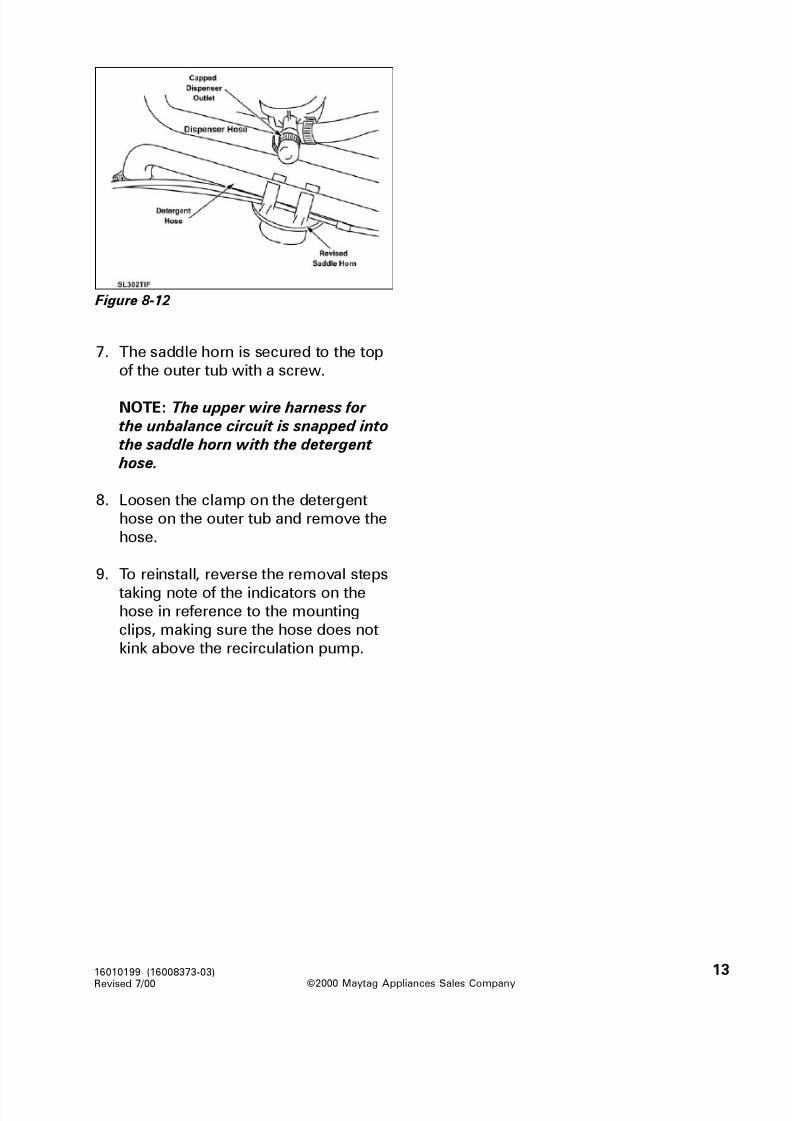
8/3/2019 Maytag MAH3000AWW Service Manual
http://slidepdf.com/reader/full/maytag-mah3000aww-service-manual 100/157
©2000 Maytag Appliances Sales Company
16010199 (16008373-03)
Revised 7/00
13
Figure 8-12
7. The saddle horn is secured to the top
of the outer tub with a screw.
NOTE: The upper wire harness for
the unbalance circuit is snapped into
the saddle horn with the detergent
hose.
8. Loosen the clamp on the detergent
hose on the outer tub and remove the
hose.
9. To reinstall, reverse the removal steps
taking note of the indicators on thehose in reference to the mounting
clips, making sure the hose does not
kink above the recirculation pump.

8/3/2019 Maytag MAH3000AWW Service Manual
http://slidepdf.com/reader/full/maytag-mah3000aww-service-manual 101/157
©2000 Maytag Appliances Sales Company
16010199 (16008373-03)
Revised 7/00
14
SECTION 9. WIRING INFORMATION
Please refer to the technical schematic packed in the control console in the washer for
up to date wiring information for the product your are servicing. The schematics on the
following pages are only a general reference at the time this manual was printed.

8/3/2019 Maytag MAH3000AWW Service Manual
http://slidepdf.com/reader/full/maytag-mah3000aww-service-manual 102/157
©2000 Maytag Appliances Sales Company
16010199 (16008373-03)
Revised 7/00
15
SERIES 10 - SCHEMATIC (MAH4000 only)
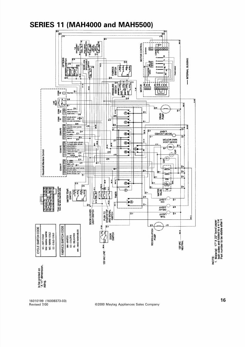
8/3/2019 Maytag MAH3000AWW Service Manual
http://slidepdf.com/reader/full/maytag-mah3000aww-service-manual 103/157
©2000 Maytag Appliances Sales Company
16010199 (16008373-03)
Revised 7/00
16
SERIES 11 (MAH4000 and MAH5500)

8/3/2019 Maytag MAH3000AWW Service Manual
http://slidepdf.com/reader/full/maytag-mah3000aww-service-manual 104/157
©2000 Maytag Appliances Sales Company
16010199 (16008373-03)
Revised 7/00
17
SERIES 10 - TIMER CHART (MAH4000)

8/3/2019 Maytag MAH3000AWW Service Manual
http://slidepdf.com/reader/full/maytag-mah3000aww-service-manual 105/157
©2000 Maytag Appliances Sales Company
16010199 (16008373-03)
Revised 7/00
18
SERIES 11 - TIMER CHART (MAH4000 & MAH5500A)

8/3/2019 Maytag MAH3000AWW Service Manual
http://slidepdf.com/reader/full/maytag-mah3000aww-service-manual 106/157©2001 Maytag Appliances Sales Company
16010486
(16008373-05)
16008373-05
Attached is Supplement five for service manual 16008373.
This Maytag Washer Service Manual supplement covers Models MAH5500B and
MAH7500. The following information is supplemental to the information found in the
basic manual part number 16008373. Please refer to this manual for detailed service
information.
We suggest you file this with your 16008373 Manual for reference.
MAYTAG
New CenturyNeptune Washer
Service Manual
Supplement

8/3/2019 Maytag MAH3000AWW Service Manual
http://slidepdf.com/reader/full/maytag-mah3000aww-service-manual 107/157©2001 Maytag Appliances Sales Company16010486 (16008373-05)Revised 02/01 iii
INTRODUCTION
Attached is supplement five (16008373-05) for service manual 16008373, which in
addition to supplement three (16008373-03). This Maytag Washer Service Manual
supplement covers Models MAH5500B & MAH7500A. We suggest you file this with
your 16008373 Manual for reference.
Models covered in this manual supplement:
MAH5500B MAH7500A
CONTENTS
SECTION 1. GENERAL INFORMATION ............................................................... 1-1
SECTION 2. WASHER CONTROLS OVERVIEW.................................................. 2-1
SECTION 3. DIAGNOSTIC/HELP CODE TABELS ............................................... 3-1
SECTION 4. ELECTRICAL COMPONENTS & TESTING...................................... 4-1
SECTION 5. TEARDOWN & WIRING INFORMATION ......................................... 5-1
For additional information on material covered in this manual, including safety issues,
contact:
Maytag Appliances Sales Company
240 Edwards Street, S.E.
Cleveland, TN 37311
Phone: 423-472-3333

8/3/2019 Maytag MAH3000AWW Service Manual
http://slidepdf.com/reader/full/maytag-mah3000aww-service-manual 108/157©2001 Maytag Appliances Sales Company16010486 (16008373-05)Revised 02/01 iv

8/3/2019 Maytag MAH3000AWW Service Manual
http://slidepdf.com/reader/full/maytag-mah3000aww-service-manual 109/157©2001 Maytag Appliances Sales Company
1-116010486 (16008373-05)Revised 02/01 Section 1. General Information
YTICAPAC teeFcibuC1.3
LACIRTCELE.ylppuslacirtceledesufrorekaerbtiucricpma51seriuqeR;zH06,stloV021
.teltuodeziralopdnadednuorgylreporpaotdetcennocebtsumdrocrewoP
ROTOMlortnocrotomrossecorporcimaybdellortnocrotoMecnatculeRdehctiwS
ot1.41)B0055HAM(1ot41)MPRrennipSotrotoM(oitaRyelluProtoM.draob)A0057HAM(1
EGASUREWOP
sttaW071-elbmuThsaWgniruD:tupnIrotoMsttaW0031-retaeh /welbmuThsaWgniruD
sttaW591-elbmuTesniRgniruDsttaW008-nipSpoT
).nipsnisehtolconhtiwnekatsgnidaeregattaW(
DEEPSRELBMUT
MPR55-74elbmuThsaWMPR55-74elbmuTesniR
nipSdeepShgiH (MPR008 + nipsmumitponopudesabMPR05)ecnamrofrep )B0055HAM(rehsaWDEL.mpr0001tametsysfogninutoNMPR0001
)A0057HAM(rehsaWDCL
EGASURETAW
esohtelnita)mc /gk44.8-60.1(.I.S.P021-02ebdluohserusserpretaWsehtolchtiwseirav,snollag52yletamixorppasiegasuretawlatoT.noitcennocmaesraerehtraenderusaem,sehtolconhtiwteksabnipsehtnillifretaW.daol
teksabnipsehtfosehcni3-2LEVELHSAWsehcni5-3LEVELESNIR
SHTGNELESOH.evlavretawotdehcattadnasrehsawtelnihtiwsesohtelnitoofruoF
.epipdnatsniard"63etadommoccalliwdnapmupotdehcattaesohniarD
SNOISNEMID 72xW)mc85.86("72:snoisnemiDtenibaC 2 /1 H)mc44.19("63xD)mc58.96("
).xorppA(THGIEW .xorppA).gk58(.bl781detarC.xorppA).gk08(.bl771denotracnU
TLOB&WERCSSEUQROT
(.sbl.tf7thgieWretnuoC,tloB + ).sbl.tf3(.sbl.tf83yelluPnipS,tloB + ).sbl.tf3(.sbl.tf22retsujdAtleB,tloB + ).sbl.tf2(.sbl.ni52elffaBtnorF,wercS + ).sbl.ni3(.sbl.ni5.81elffaBraeR,wercS + ).sbl.ni3
.sbl.ni+51sesoH,pmalC(.sbl.tf81troppuSrennipS,stuN + ).sbl.tf3(.sbl.tf7sturtsnoisnepsuS,stuN + ).sbl.tf3
SPECIFICATIONS
MAH5500B CONTROL FACIA MAH7500 CONTROL FACIA
(LED Screen) (LCD Screen)
SECTION 1. GENERAL INFORMATION
8/3/2019 Maytag MAH3000AWW Service Manual
http://slidepdf.com/reader/full/maytag-mah3000aww-service-manual 110/157©2001 Maytag Appliances Sales Company
1-216010486 (16008373-05)Revised 02/01 Section 1. General Information
BASIC MACHINE OPERATION
Models MAH5500B and MAH7500 are similar to the MAH4000 washer, with the exception
being they do not have recirculation of the wash water. A special sump cap is placed directly
above the sump area which catches the detergent and allows for a better mixing of the
detergent and the wash water. The door lock mechanism was updated from a wax motor
system to a solenoid, resulting in faster locking and unlocking of the door. The water level
pressure switch was relocated from the console to the top of the pump, thus eliminating theairdome hose. The motor drive system was changed to a sensorless system, thus eliminating
the tach sensor in the motor in the harness leading to the motor control board. Heater with
thermistor was added to the sump area of the tub to heat the wash water on the MAH7500A
model.
General Flow Of A Complete Wash CycleThere are several user selections which modify the main wash. Fabric selection impacts tumble
pattern. Wash/rinse temperature selection determines water fill temperature. Soil level and
quick wash selections determine wash time. The Stain cycle and Presoak options add addi-
tional time with a special tumble pattern to the main wash. The stain cycle option also adds
rinse time to non-heavy cycles and some warmer rinses. The Quick cycle reduces wash timeand only has two rinses. For this cycle, less detergent should be used.
1) The wash cycle is selected and started by user by pressing Start/Pause button
2) The door lock mechanism is verified by locking it and unlocking it. The door is left unlocked.
3) The drain pump will turn on (energized) for a short period of time.
4) The water fill will begin after a delay from the time the pump is turned off. The temperature
of the water entering the tub depends on the user selections.
5) After 30 seconds the door will be locked and the machine will tumble at the Handwash wash
tumble pattern (less aggressive) until the machine is at wash level. The exception would be
if the Cotton/Sturdy is selected or Quick cycle and the washer would have a 7/3 tumble
pattern. Note: No permanent locking, tumbling, or spinning shall be done for 30 seconds
after any cycle is started or re-started. Filling and draining will be allowed in this initial
period. Once filled, the tumble pattern and the total wash time depends on the user selec-
tions. A Wash Tumble Flush occurs shortly after the water reaches the wash fill level. A
Wash Tumble Flush will have special tumbling speed to ensure the proper mixing of the
detergent.
7) Shortly before the end of the wash cycle bleach will be dispensed.
8) The washer will then drain and spin.
9) The washer will fill tumble, drain, and spin repeatedly to rinse the clothes. The number of
rinses and spin speeds will be dependent on user selections. Toward the end of the wash
and rinse spin, the cold water valve will be turned on for 6 seconds. During the final rinse the
machine will perform a tumble flush to clean the machine.
10) A final drain and high speed spin will be performed to extract the water from the clothes.

8/3/2019 Maytag MAH3000AWW Service Manual
http://slidepdf.com/reader/full/maytag-mah3000aww-service-manual 111/157©2001 Maytag Appliances Sales Company
1-316010486 (16008373-05)Revised 02/01 Section 1. General Information
CYCLE SEQUENCES
snoitceleShsaW emiTgnilbmuT
yvaeHartxE)a)ylnOledoMDCL(
setunim23elbmuthsaw
hcaelbetunim2 .llif
yvaeH)bsetunim72
elbmuthsawhcaelbetunim2
.llif
lamroN)csetunim41
elbmuthsawhcaelbetunim2
.llif
thgiL)d hsawsetunim8 elbmuthcaelbetunim2
.llif
kciuQ)ehsawsetunim3
elbmuthcaelbetunim2
.llif
Wash Time Tumble:snoitceleScirbaF gnilbmuTcisaB
deepSdnanrettaP
ydrutS /nottoC)a rofmpr74ta3 /7
eerFelknirW)b mpr15ta3 /5
setacileD)c mpr15ta42 /6
hsawdnaH)d mpr15ta72 /3
tpecxellaroflliF)e
dnaydrutS /nottoC
hsaWkciuQ
mpr15ta72 /3
hsaWkciuQ)f
llafosseldrager(
)snoitcelescirbaf
mpr15ta3 /7
Note: �7/3� means 7 seconds on, 3 seconds off,
reverse direction and repeat.
Basic Tumble Patterns:
esniRsnoitceleS
emiTgnilbmuT
rolamroN)aniatson,thgiL
setunim3-esniRts1setunim3-esniRdn2
setunim3-esniRartxE*setunim3-esniRdr3
artxE,niatS)broyvaeH
yvaeH
setunim5.4-esniRts1setunim5.4-esniRdn2
setunim5.4-esniRartxE*setunim5.4-esniRdr3
kciuQ)csetunim2-esniRts1
setunim2-esniRartxE*setunim2-esniRdn2
esniR)d setunim3-sesniRllA
Rinse Tumble Times:
*Note: The final rinse time does not include the
Tumble Flush time. Tumble Flush time will add a
minimum of 30 seconds to a maximum of 60
additional seconds to the final rinse time. (See
definition of Tumble Flush)
artxE
,yvaeH
,yvaeH ,lamron
thgilro
kciuQ esniR nipS --artxE
esniR
niatS fo.oN
sesniR
X 3
X 2
X X 3
X 4-1
X 0
X X 4
X X X 4
X X 4
X X 2B0055HAM
X X 4-20057HAM
Number of Rinses:

8/3/2019 Maytag MAH3000AWW Service Manual
http://slidepdf.com/reader/full/maytag-mah3000aww-service-manual 112/157©2001 Maytag Appliances Sales Company
1-416010486 (16008373-05)Revised 02/01 Section 1. General Information
deepSnipS pmuPniarD
mpr045<)a suounitnocnO
.noitubirtsiderninehwmpr001<)b ffO
tsrifehtgniruddnampr045=>)c
etunim
ffodnoces51dnanodnoces51
.elcycytud
retfasdnoces03dnampr045=>)d
tegratehtdehcaersahenihcameht
.deeps
ffosdnoces54dnanodnoces51
.elcycytud
nipslanifgnirudnwodtsaoC)e MPR003sehcaerenihcamlitnuffO
enihcamehtlitnunonehtdna
.MPR0sehcaer
snipsrehtollagnirudnwodtsaoC)f ehtnipetstxenlitnusuounitnocnO
elcyc
ON/OFF SEQUENCE OF PUMP DURING SPIN CYCLE
The water temperature entering the washer during rinse is tempered. The following
table shows the temperature based on the user selections.
,kciuQ,y vaeHartxE
thgilro,lamron,y vaeh detceleSnoitpO
detceleS
erutarepmeT
esniR niatS
elcy C
retawesniR
erutarepmet
Y dna,C/W,C/H
C/C
N N .dlocderepmet-noN
Y W/W N N esnirlanif ehtrof F°08
dlocderepmet-noN.ylno
.sesnirrehtollarof
N dna,C/W,C/H
C/C
Y N dlocderepmet-noN
N W/W Y N F°08sesnirll A
Y
thgildna,lamron,yvaeh(
de w ollatonsikciuq,ylno
)niatshti w
dna,C/W,C/H
W/WDN AC/C
N Y ehtsiesnirtsrif ehT
hsa w ehtsaemas
f otserehT.erutarepmet
emasehterasesnireht
tonsa w elcycniatsf isa
.detceles
INPUT WATER TEMPERATURE

8/3/2019 Maytag MAH3000AWW Service Manual
http://slidepdf.com/reader/full/maytag-mah3000aww-service-manual 113/157©2001 Maytag Appliances Sales Company
2-116010486 (16008373-05)Revised 02/01 Section 2. Washer Controls Overview
SECTION 2. WASHER CONTROLS OVERVIEW
The software for the MAH5500B and the MAH7500 is different than the MAH4000
washer. The new controls operate via a membrane pad on the MAH5500 and a touch
screen/membrane pad on the MAH7500 washer.
Features of MAH7500 (LCD Washer):
� A membrane switch (keyboard) with a
LCD display and touch screen.
� The user can select a delay start.
� The wash/rinse temperatures and wash
cycles are remembered and based on
the previous fabrics type selected.
� The control panel drives a heater located
in the sump.
� The control displays the estimated time
remaining in the cycle.� The control panel detects hose reversal
and changes the fills as necessary.
� The control panel stores codes to aid the
service person in diagnostics.
Figure 1
Features of MAH5500B (LED Washer):� A membrane switch (keyboard) with an
embedded LED display.
� The user can select a delay start.
� The wash/rinse temperatures and wash
cycles are remembered and based on
the previous fabric type selected.
� The user can select another wash cycle
during the operation and the control will
determine the completion of the cycle.
� The control panel displays the estimatedtime remaining in the cycle
� The control panel stores codes to aid the
service person in diagnostics.
� The control panel detects hose reversal
and changes the fills as necessary.
BASIC CONTROL BOARD PHILOSOPHY FOR BOTH WASHERS:

8/3/2019 Maytag MAH3000AWW Service Manual
http://slidepdf.com/reader/full/maytag-mah3000aww-service-manual 114/157©2001 Maytag Appliances Sales Company
2-216010486 (16008373-05)Revised 02/01 Section 2. Washer Controls Overview
USER INTERFACE
SELECTIONS: (LED Washer)
The user can select the setting of several
features while in the User Interface Active
Mode or the Main Wash Cycle. The user
sets the features by pressing a key on thekeypad and the machine goes into the set
mode. If the machine is in the main wash
cycle, additional criteria may be applied
prior to changing the feature. The modes
to set a feature are:
� Fabric Mode
� Temperature Mode
� Cycles Mode
� Delay Mode
� Signal Mode� Options Mode
FABRIC MODE
When a Fabrics key is pressed, the last
cycle that was not a Quick, Rinse, or Spin
cycle, will be recalled. Each Fabrics key
(Cotton/Sturdy, Wrinkle Free, Delicates,
Handwash, ) remembers the wash/rinse
temperature settings, max extract option,
extra rinse option, and wash settings.
TEMPERATURE MODE
Four discrete wash/rinse temperature
selections are provided, each with an
associated LED. Up and down arrow keys
are used to make the wash/rinse
selection. Holding down one of these
keys will advance at a rate of one level per
half second. Wash/rinse selection will not
wrap around.
CYCLES MODE
When a wash key is selected (heavy,
normal, light, quick, rinse, or spin), the
LED shall be lit and remain lit until another
wash cycle is selected. The wash LEDs
do not change during the wash cycle.
DELAY MODE
The delay start option is primarily used
when a person wants to run the washing
machine at night or some other time tobetter suit the needs of the household.
The consumer can select the time delay from 1 hour to 9 hours in increments of 1hour. The user shall press the delay button for each 1 hour increment. Holding down
the delay wash key will advance throughthe one hour increments to off and startover again.
The delay time (in hours) shall be shownin left digit and an �H� (for hours) shall beshown in the right digit of the display.
If delay wash has been selected, but Start/Pause has not been pressed to initiate it,
then the Start/Pause LED will flash off andon to indicate that it must be pressed.The Start/Pause key must be pressed toinitiate a delay wash cycle. Once it hasbeen pressed, the Start/Pause LED willstay on constant and the time will begin tocount down and the display will indicatehours of delay remaining. When one hourof the delay is reached, the time will beshown in minutes in the two digits of thedisplay.
Note: If a regular cycle has been running for more than five seconds, thedelay wash key will be locked out.
SIGNAL MODEThe volume level of the end of cyclesignal is adjustable. The sound ranges from �off� to �3� in increments of 1. Theuser will be able to select the plus (+) toincrease the volume level. The user will
be able to select the minus (-) to decreasethe volume level. When the user firstpresses either of these keys, the currentend of cycle signal will be demonstrated.
Subsequent presses of either the plus orminus button within 5 seconds of theprevious key press will increase ordecrease one level. The new end of cycle
shall sound.

8/3/2019 Maytag MAH3000AWW Service Manual
http://slidepdf.com/reader/full/maytag-mah3000aww-service-manual 115/157©2001 Maytag Appliances Sales Company
2-316010486 (16008373-05)Revised 02/01 Section 2. Washer Controls Overview
OPTIONS MODE
When the extra rinse key is selected, an
extra rinse is added for the wash cycles.
(Page 1-3 Extra Rinse Table)
When max extract speed key is selected,
the max extract profile will be used for
spin cycle based on the fabric selection.
When the stain cycle key is selected, the
water input temperature, the wash time,
the tumbling pattern, speed, and amount
of rinses may be modified.
When the presoak key is selected, a
presoak is added before the main wash
cycle.
DISPLAY CHARACTERISTICS
Door Locked LED:
When the door is finally locked, the door
locked LED is lit. When the door is finally
unlocked, the door locked LED is not lit.
Two Digit Display:
The display shows the estimated time
remaining in the total cycle in minutes.
This time will count down during the totaltime cycle.
If the selected Wash cycle button is
pushed, the estimated time remaining in
that wash cycle shall be displayed for 5
seconds and the associated Wash level
LED will flash. After 5 seconds, the
estimated time remaining for the total
cycle will be displayed and the wash level
LED will return to being on constant.
Changing Selections:
Fabric, temperature, and options
selections may be changed at any time.
The current cycle step will be suspended
and the appropriate cycle step will be
restarted with the new selections. The
machine will not stop, but rather thechanges will be dynamic.
The main Wash Keys may be changed at
any time. The cycle time remaining is
recalculated and displayed. The
remaining time is calculated by applying
the actual time in the new cycle. If the
user had originally selected Heavy wash
and 3 minutes has elapsed and the user
then selects Normal wash, the time
remaining will be 12 minutes. (e.g. 15minutes Normal wash minus 3 actual
minutes = 12 minutes). If the user had
originally selected Quick wash, 1 minute
had elapsed, and then the user selects
Heavy wash, the new remaining time will
be 19 minutes (20 minutes heavy wash
minus 1 minute actual time).
The main Wash key may not be changed if
there is less than 2 minutes time
remaining in the wash cycle (Bleach Fill).Although the button can be depressed,
the LED status will change but the time
remaining or wash cycle will not change.
USER INTERFACE SELECTIONS:
(LCD Washer)
All selections described under the LED
washer section are familiar except in the
Delay mode. In this mode, time isincreased in 15 minute increments up to
12 hours.

8/3/2019 Maytag MAH3000AWW Service Manual
http://slidepdf.com/reader/full/maytag-mah3000aww-service-manual 116/157©2001 Maytag Appliances Sales Company
2-416010486 (16008373-05)Revised 02/01 Section 2. Washer Controls Overview
INPUT MODIFICATIONS DEFINED
PRESSURE SWITCH INPUTThe pressure switch is a two level pressure switch. (Figure 4-2) The low level contactsprovide a path for a 24 VDC sensing circuit, the high level contacts provide an electricalpath for 110 VAC to the water valve relays on the board. Another sensor on the boardmonitors the high level circuit to determine when the high level is reached and the
circuit is opened. Thus, shutting off the water valve relays.
During wash fill, the low level of the pressure switch is sensed with 24 VDC and providesan indication to the control board the water level has satisfied the low level. Oncesatisfied, the 24 VDC circuit is opened. The board then opens the water valve relays andshuts off the water valves.
During rinse fill, the high level provides an indication to the machine control as towhether the high water level has been reached. When the water level switch is satisfied,the pressure switch circuit is opened and power for the water valves is no longer passedthrough the machine control.
Figure 2
TEMPERATURE SENSOR INPUTA thermistor is located in the water valveto monitor the blended incoming watertemperature. The machine control usesthis input signal to regulate the watertemperature with the warm or cold washand warm rinse temperature selections(See Water Valve Outputs).
On the MAH7500 model, anotherthermistor is located on the heaterassembly. The machine control boarduses this input signal to maintain thewater temperature in the sump area of the outer tub, by cycling the heater on/off.
DOOR LOCK SWITCH INPUTWhen input is present, this is indicationthe washer door is locked. The machinecontroller will not command the spinnerto tumble or spin when the door lockinput is not present.
If the door is opened during a cycle,the control will pause the cycle on theMAH5500B.
8/3/2019 Maytag MAH3000AWW Service Manual
http://slidepdf.com/reader/full/maytag-mah3000aww-service-manual 117/157©2001 Maytag Appliances Sales Company
2-516010486 (16008373-05)Revised 02/01 Section 2. Washer Controls Overview
START/PAUSE INPUTThe start/pause input is selected on themembrane switch for both washers. If this input is initially selected the machinecontrol will begin the wash cyclesequence as defined by the user inputselections. If this input is selected when a
cycle is in progress, the machine controlwill pause the cycle and unlock the doorwhen it is safe to do so.
(Note: Machine control board is powered up all the time. There no longer is a line relay used, as opposed tothe MAH3000, 4000 and 5500A models.)
TACH INPUTThe tach input is a feedback signal fromthe motor control. It provides eightpulses per revolution of the switchedreluctance motor. The motor runs at 14times the speed of the spinner (14:1 beltratio). The tach input is used formonitoring speed and out-of-balancedetection (See Tachometer Circuit Diagnostics).
If the machine control commands a motorspeed and direction but does not sense atach input signal within 2 or 3 seconds, itwill assign a HELP code number andperform 10 retries. If unsuccessful, thisgenerally indicates a locked rotor or amalfunction in the motor control.
If the machine control commands a coastdown from final spin speed but is stillreceiving a tach input signal after twominutes, it will log appropriate service
codes.
OUTPUT MODIFICATIONS
DEFINED
DOOR LOCK/UNLOCKSOLENOID OUTPUTThe Door Lock/Unlock Solenoid Output
signal is a 60 millisecond pulse sent to asolenoid in the door lock assembly. Thesolenoid is attached to a lever whichmoves a slider in the mechanism to lockthe door after it has been closed and thecycle started. The solenoid has two coils,one for locking and one for unlockingwhen a pulse is directed to specificterminals on the solenoid. Power is notcontinuously applied to the solenoid,because this would damage the solenoid.
END-OF-CYCLE SIGNAL OUTPUTThe End-Of-Cycle Signal Output is aninternal signal on the machine controlbetween the microprocessor andannunciator. The end-of-cycle signalsounds when a wash cycle is finished.The end-of-cycle signal sounds as fourpulses on the MAH5500B and 3 pulses onthe MAH7500 in a 0.5 second intervals. If the door is opened right at the end of the
cycle or during the end of cycle beeps,then the signal will stop on the MAH5500Bonly. If the start/pause key is pressednear the end of the cycle, the end of cyclesignal will not occur unless the cycle isrestarted and allowed to finish. If the Off key is pressed, the end of cycle signal willnot occur. The end of cycle signal willoccur when the door is unlocked andready to open on the MAH5500B. On theMAH7500, the signal sounds then the
door is unlocked.
HEATER OUTPUT (LCD Washer only)
The machine control board turns the
heater on to heat the wash water during
the main wash until the temperature
reaches the targeted main wash
temperature. The heater is turned back
on at any point the temperature falls 5º F

8/3/2019 Maytag MAH3000AWW Service Manual
http://slidepdf.com/reader/full/maytag-mah3000aww-service-manual 118/157©2001 Maytag Appliances Sales Company
2-616010486 (16008373-05)Revised 02/01 Section 2. Washer Controls Overview
resUsnoitceleS
retawtupnIderepmet
mumixaMnoretaeh
emit
-hsaWdloCretaehon
retawdloCderepmeT
hsaw
A /N
hsaWdloCniatshtiw
&noitpoelcyc.retaeh
taehlliW,F°56fiF°56otretaw
.yrassecen
niaMemithsaw
-hsaWmraWretaehon
retawmraWderepmeT
mraw
A /N
hsaWmraWniatshtiw
noitpoelcyc.retaehdna
taehlliw,F°501fiF°501ot
yrassecen
niaMemithsaw
on-hsaWtoHretaeh
retawtoH A /N
htiwhsaWtoH
dnaelcycniats.retaeh
neht,retawtoH
fiF°031ottaehyrassecen
niaM
emithsaw
below the main wash target temperature.
The heater monitors the water
temperature through the thermistor in the
heater assembly. Selecting the energy
saver, will turn off the heater and will not
affect tumble patterns.
Main Wash Target Temperatures
The heater will not be turned on if the
following conditions exist:
1. Low level of the water pressure switch
is not satisfied.
2. The door is open.
3. During the Bleach fill.
4. Energy Saver on.
DOOR LOCKED LIGHT OUTPUT
The Door Locked Light Output signal
powers a LED on the membrane pad
switch of the LED washer. This output is
energized when the washer door is
locked.
VDC REFERENCE VOLTAGE OUTPUT
The VDC Outputs are a reference voltage
for many of the signal outputs. On the
machine control, the VDC outputs are 24
VDC referenced from P2(3) to the
individual outputs.
WATER VALVE OUTPUTS
The machine control determines whether
the hot or cold Water Valve Outputs
should be energized during the wash
cycle based upon the user selections.
When water fill is required, the machine
control board will activate relays on the
board, supplying power to the water
valves.
The machine control gates the power tothe hot and cold Water Valve Outputs.
When the pressure switch senses that the
full level is reached, the circuit opens and
the machine control de-energizes the
Water Valve Outputs.
The machine control will monitor the
thermistor resistance and fill time to
achieve proper wash temperatures.
During a warm wash the cold may becycled off periodically to achieve the
desired water temperature.
On a cold wash the hot valve may be
cycled on and off.
CYCLE SEQUENCE DEFINITIONS
IDLE/PAUSE MODE (LED Model)
After pressing the Off key, the entirewashing machine will shut down after
unlocking the door and will be in the Idle
Mode. In the idle mode all the outputs are
de-energized, all the LEDs and display are
off.

8/3/2019 Maytag MAH3000AWW Service Manual
http://slidepdf.com/reader/full/maytag-mah3000aww-service-manual 119/157©2001 Maytag Appliances Sales Company
2-716010486 (16008373-05)Revised 02/01 Section 2. Washer Controls Overview
If the Start/Pause key is pressed duringthe wash cycle the washer shall stop allthe functions of the washer, placing thewasher in the Idle Mode. The Start/PauseLED will flash indicating the pause mode.The current place in the cycle will besaved.
If the Start/Pause key is pressed the doorwill not be unlocked until the spin speedis 0 rpm.
If the Start/Pause key is pressed while flashing (in pause mode), the machineshall return to the start of the cycle stepwhen paused and the time displayed berecalculated to the start of the cycle step.The Start/Pause LED will stay on
whenever the machine is running in acycle. Note: The door must be closedprior to resuming the cycle.
BLEACH DISPENSEThe Bleach Fill occurs 2 minutes prior tothe end of the wash portion of the cycle. Ableach fill consists of turning the bleachwater valve and the appropriate fill watervalve(s) on until the water reaches highwater level or for 24 seconds, whichever
comes first. This is to ensure the bleach isused completely during this wash. The fill temperature during the Bleach fill shallbe based on the user selections. If staincycle is selected then bleach fill and finalrinse are based on user selections. If staincycle is not used, then only the final rinseis affected.
REDISTRIBUTIONAs the machine is accelerating into spin, if
it detects that the clothes load isunbalanced and would cause excessivevibration, it will decelerate and tumble theclothes in an attempt to redistribute themin a more uniform manner so thatvibration is reduced.
The machine control commands adistribution profile speed ramp from 0rpm to 85 rpm at the beginning of each
high speed (above 100 rpm) spin. Whenthe washer reaches 85 rpm, the machinecontrol monitors the Tach Input todetermine if the speed varies through onerevolution of the spinner basket. If itsenses a high enough variation in speed(suggesting an out-of-balance condition in
the clothing load), it will drop the spinnerspeed to 0 rpm and force a short reversetumble to redistribute the clothing loadbefore resuming the spin. If any of theout-of-balance switches trip and open theout-of-balance input circuit at a speedbelow 500 rpm, the machine control willalso drop the speed to 0 rpm and forcethe reverse tumble to redistribute theclothing load before resuming the spin.
SUDS DETECTIONThe suds detection feature tries toeliminate excessive suds during the mainwash or rinse cycles. Suds detection isdisabled during a stain cycle tumblepattern.
If suds are detected, the estimated timeleft on the wash cycle will be modified toaccount for 4 additional rinses.
The washer will try twice in early spinsand 21 times when in the final spin.
LCD Washer: If four out of seven cycleshave suds detected, �Too many Sudsdetected� should be displayed on thescreen.
LED Washer: If suds are still detected, the�rinse� LED shall blink, 3 seconds on, 3 sec-
onds off and "sd" will be displayed.
TUMBLE FLUSH (Two types of flush)Wash tumble is a higher tumble speedthan normal while the machine is filledwith water. The purpose of this function isto clean the machine. Rinse tumble flushis performed during the final rinse toreduce the chance of suds creation.

8/3/2019 Maytag MAH3000AWW Service Manual
http://slidepdf.com/reader/full/maytag-mah3000aww-service-manual 120/157©2001 Maytag Appliances Sales Company
2-816010486 (16008373-05)Revised 02/01 Section 2. Washer Controls Overview
DOOR LOCK PHILOSOPHY
The door lock mechanism is checkedby the machine control board forproper operation. This is done in the
following manner.
1. The door will be locked. If the doordoes not lock on the first try, a helpcode 47 is logged into the controlmemory. The display will show thedoor has not locked.
2. If the door lock switch check showsthat the door is locked, then the doorwill be unlocked and the cycle will
continue unless the door fails tounlock. If the door fails to unlock, thecycle will be paused until the door isable to unlock for 30 seconds and lockagain.
DOOR LOCK OPERATION1. By closing the door, the door lock
hoop rotates the catch cam and thedoor actuator is depressed actuatingthe door open/closed microswitch.
MISCELLANEOUS 2. A 60 milliseconcd 120 VAC impulse from the machine control board to thelock solenoid extends the push rod of the solenoid and moves the lock leverto the right only to lock the door. Thelock lever in turn is engaged with theslider and slides the slider toward the
door lock mechanism and inhibits thedoor lock mechanism from releasingthe door lock hoop of the door.
5. The slider will actuate the door lock/unlock microswitch in the lockedposition and the washer will begin thewash cycle.
6. When the wash cycle is finished animpulse from the machine controlboard to the unlocking solenoidunlocks the door by pulling the slideraway from the door latchingmechanism and the lock/unlockmicroswitch.
7. The consumer can now open the door.
8. By opening the door, the open/closedmicroswitch is open.
DoorLock/UnlockSolenoid
EmergencyCord
MechanicalOpener
CamSupport
Door Open/ClosedSwitch
Door LockSpring
RotatingCam
Lamp Socket& Lamp
Door Actuator
Door Lock/UnlockSwitch
LockingLever
SolenoidPush-Rod

8/3/2019 Maytag MAH3000AWW Service Manual
http://slidepdf.com/reader/full/maytag-mah3000aww-service-manual 121/157©2001 Maytag Appliances Sales Company
2-916010486 (16008373-05)Revised 02/01 Section 2. Washer Controls Overview
MAH5500B:
:devaSnoitamrofnI :esuaC
tsaLehtfogninnigebehT.demrofreppetselcyc
ssol-rewoP
ecafretnIresUtnerruCsnoitceles
ssol-rewoP
latoteht,sedoccitsongaiDscitsongaidehtforebmun
rebmuncitsongaidecnis.deraelcneebsah
derrucconehW
nurselcycforebmunehT afodnEdetelpmoc
.elcychsaw
POWER LOSS/FAILURE
Power-up after a power-loss during a main
wash cycle. The machine cycle will re-
sume at the appropriate cycle step after
the Start/Pause key has been pressed. The
control recovers the saved information on
power-up after a power loss. The recov-
ery will be to the appropriate step in the
cycle and within 3 minutes of the cycle
step where the power loss occurred. The
LCD display will be reset to the appropri-
ate time left after the Start/Pause key has
been pressed and not indicate a power
failure at that point. The main wash cycle
will resume immediately after the Start/
Pause key has been pressed.
When a power loss occurs during the finalspin of a main wash cycle, the cycle will
end, on the MAH5500B. The MAH7500A
will finish the spin cycle.
Power-up after a power-loss during service
mode, continuous mode, or advertising
mode will cancel these modes.
These modes will not resume after the
power-up until the user selections are
pressed again.
If a power outage occurs during a cycle the
washer will come back up in the paused
state. When paused (either by a power
outage or by the user), the washer will
remember where it was. The machine will
not automatically time-out and cancel a
cycle while paused. The display will re-
main on for 10 minutes after it is paused
with no activity. After 10 minutes of no
activity, the display will turn off, but the
machine will remember where it was andthe display will be turned back on with any
user activity.
SPECIAL FEATURES
The LCD and LED washers come withseveral new features not available with theearlier versions of the Neptune washers.
By pressing a combination of keys, thewasher can be placed into an AdvertisingMode or into a Service Mode for theservice technician.
ADVERTISING MODEThis mode will continuously display theLEDs on the keyboard or illuminate theLCD touch screen.
MAH7500A:Continuously monitors and saves infor-
mation to memory every minute or as
cycle selection change.
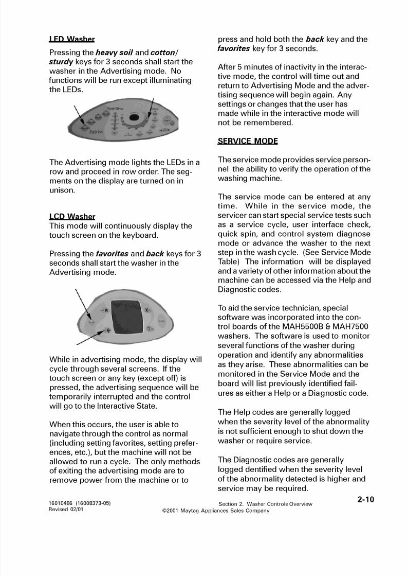
8/3/2019 Maytag MAH3000AWW Service Manual
http://slidepdf.com/reader/full/maytag-mah3000aww-service-manual 122/157©2001 Maytag Appliances Sales Company
2-1016010486 (16008373-05)Revised 02/01 Section 2. Washer Controls Overview
LED Washer
Pressing the heavy soil and cotton/ sturdy keys for 3 seconds shall start thewasher in the Advertising mode. No functions will be run except illuminatingthe LEDs.
The Advertising mode lights the LEDs in arow and proceed in row order. The seg-ments on the display are turned on inunison.
LCD WasherThis mode will continuously display thetouch screen on the keyboard.
Pressing the favorites and back keys for 3seconds shall start the washer in theAdvertising mode.
While in advertising mode, the display willcycle through several screens. If thetouch screen or any key (except off) ispressed, the advertising sequence will betemporarily interrupted and the control
will go to the Interactive State.
When this occurs, the user is able tonavigate through the control as normal(including setting favorites, setting prefer-ences, etc.), but the machine will not beallowed to run a cycle. The only methodsof exiting the advertising mode are toremove power from the machine or to
press and hold both the back key and the favorites key for 3 seconds.
After 5 minutes of inactivity in the interac-tive mode, the control will time out andreturn to Advertising Mode and the adver-tising sequence will begin again. Any
settings or changes that the user hasmade while in the interactive mode willnot be remembered.
SERVICE MODE
The service mode provides service person-nel the ability to verify the operation of thewashing machine.
The service mode can be entered at anytime. While in the service mode, theservicer can start special service tests suchas a service cycle, user interface check,quick spin, and control system diagnosemode or advance the washer to the nextstep in the wash cycle. (See Service ModeTable) The information will be displayedand a variety of other information about themachine can be accessed via the Help andDiagnostic codes.
To aid the service technician, specialsoftware was incorporated into the con-trol boards of the MAH5500B & MAH7500washers. The software is used to monitor
several functions of the washer during
operation and identify any abnormalities
as they arise. These abnormalities can be
monitored in the Service Mode and the
board will list previously identified fail-
ures as either a Help or a Diagnostic code.
The Help codes are generally logged
when the severity level of the abnormality
is not sufficient enough to shut down the
washer or require service.
The Diagnostic codes are generally
logged dentified when the severity level
of the abnormality detected is higher and
service may be required.

8/3/2019 Maytag MAH3000AWW Service Manual
http://slidepdf.com/reader/full/maytag-mah3000aww-service-manual 123/157

8/3/2019 Maytag MAH3000AWW Service Manual
http://slidepdf.com/reader/full/maytag-mah3000aww-service-manual 124/157©2001 Maytag Appliances Sales Company
2-1216010486 (16008373-05)Revised 02/01 Section 2. Washer Controls Overview
egnaRdeepS deyalpsiD
mpr99-0)a)lautca(99-0
999-001)bmpr
01 /deepS
mpr+0001)c
tigidts1A MPR0001<ro0001=>B MPR0021<ro0011=>C MPR0031<ro0021=>
snet-tigiddn2MPR0201=2A:elpmaxE
MPR06116B
The following Quick Spin test steps are as
follows:
1) Lock the door.
2) Spin to 350 rpm and hold for 6 seconds.
3) Spin to 550 rpm and hold for 6 seconds.
4) Spin to 600 rpm and hold for 6 seconds.
5) Spin to 650 rpm and hold for 6 seconds.6 Spin to 800 rpm and hold for 6 seconds.
7) Spin to 1000 rpm and hold for 6
seconds.
If the Spin key is pressed again during the
Quick Spin test, the current speed will be
held indefinitely. Pressing the Spin key again
will allow the quick test to proceed as listed
above.
When the washer is in the spin cycleduring the Service Mode, the speed will
be displayed as follows.
QUICK SERVICE CYCLE
Pressing the delicates key will start a
quick service cycle. This will be a quick
check of all systems.
The following steps will be followed.
1. Energize the cold and bleach. Fill to
Low level, then turn bleach and cold
off.
2. Energize the hot and fabric softener.
Fill to high level, then turn all valves off.
3. Tumble using 7/3 tumble pattern for 12
sec.
4. Lock the door.
5. Turn the drain on.
6. Spin to 800 RPM using default rates.
7. End spin and Coast down.
8. Unlock the door when the RPM is zero.
9. Display a �PA� on continuously for 10
seconds if no diagnostic codes were
logged during this test.
The up arrow if pressed will advance to
the next step. The right most dot should
be turned on as an indication of failure and
stay on until quick service cycle test has
reached the end. Any diagnostic code
logged during this test should result in
failure of the test, but should not necessar-
ily stop the test.
If any steps in the quick service cycle fail,
then a service mode is entered, and the
first diagnostic code that was logged
would be displayed.
While in quick service cycle, the pressing
of the hand wash will suspend the ma-
chine at this step until the Hand Wash key
is pressed again up to 30 minutes. All

8/3/2019 Maytag MAH3000AWW Service Manual
http://slidepdf.com/reader/full/maytag-mah3000aww-service-manual 125/157©2001 Maytag Appliances Sales Company
2-1316010486 (16008373-05)Revised 02/01 Section 2. Washer Controls Overview
:desserPyeK demrofrePnoitcnuF
ydruts /nottoC evlaVretaWtoH
eerFelknirW evlaVretaWdloC
setacileD evlaVhcaelB
hsaWdnaH evlaVrenetfoScirbaF
skaoserP pmuPniarD
elcyCniatS lortnoCrotoM
esniRartxEeslupasdneS(rooDkcolnU
)sdnoces2yreve
tcartxExaMeslupasdneS(rooDkcoL
)sdnoces2yreve
LED�s will flash on and off while the cycle
is paused.
BOARD INPUT TEST
While in service mode press the hand
wash key places the washer into the
Board Input Test.
BOARD OUTPUT TEST
While in service mode, pressing the rinse
key places the washer into the Board
Output test. This test will turn on a speci-
fied output after a key press. All output
will be turned off after 10 minutes. or if
another output is selected.
:desserPyeK :noitcnuF :kcabdeeF
ydrutS /nottoC noitisoProoD nepO"0d"desolC"1d"
setacileD noitisoPhctaL dekcolnU"0L"dekcoL"1L"
eerFelknirW retaWhgiHleveL
leveLwoleB"0~"leveLevobA"1~"
hsaWdnaH retaWwoL
leveL
leveLwoleB"0_"
leveLevobA"1_"
nwoDpmeT ecnalabnUtiucriC
decnalaB"0u"decnalabnU"1u"
pUpmeT retaWerutarepmeT
.F*seergeD
nipS noitarbiVlangiS
*552-0
esniR tuOnworBleveL
*522-0
kciuQ -temoreleccA
tiucricre
sessaP=AP
sliaF=AF
yalpsidtigidowT* = ;001=DELtcartxexam;99-0.002=DELesnirartxednaDELtcartxexaM
HELP CODES
When the washer performs differently
from design, a Help code is identified andassigned. The severity level is generally
less than that of a diagnostic code.
Accessing The Help Codes
Place the washer into the service mode,
then press the stain cycle key. A �h� will
display and turn the LED on above the
Stain Cycle key.
The Help codes can be reviewed by using
the arrow keys. The up/down arrow will
go track up/down the list one code at a
time. The first code to display will be the
latest code generated. The oldest codewill be on the bottom of the list. If there
are no help codes available, �- -� will be
displayed. If the code happened on the
previous cycle, then the rightmost dot will
be turned on.

8/3/2019 Maytag MAH3000AWW Service Manual
http://slidepdf.com/reader/full/maytag-mah3000aww-service-manual 126/157©2001 Maytag Appliances Sales Company
2-1416010486 (16008373-05)Revised 02/01 Section 2. Washer Controls Overview
Number of Cycles Since Code Assigned
While this help code is displayed, if the
extra rinse key is pressed and held, the
machine shall display the number of
cycles ago the Help code occurred while
the key is held. Also, while this key is
being held, the LED will be turned on bythe key. When this key is let up, then the
help code is again displayed. If there are
no help codes available, �- -� will be
displayed while this key is pressed. If the
code is over 99 cycles ago, then �- -� will
be displayed.
Clearing the Help Codes
The list of Help Codes can be cleared from
the memory of the board, by pressing
heavy soil and stain keys for 3 secondswhile viewing the list.
For a listing of available Help codes, see
Section 5: DIAGNOSTIC/HELP CODE
TABLES.
DIAGNOSTIC CODES:
When a problem with the wash system is
detected a diagnostic code is assignedand logged into the control board
memory with the last cycle count at which
it occurred. Diagnostic codes are
generally more severe than a Help code.
In some cases, when the washer shuts
down, something shall be displayed on
the display until the consumer presses a
key or opens the door. See the table for
specific actions or references to where
the proper action is defined.
Accessing Diagnostic Codes
After the machine is in the service mode,
pressing presoak key will display a �d�
and turn the LED on above the presoak
key. The diagnostic codes can be viewed
by using the arrow keys. The down arrow
will go down the list.
The first time the down arrow key is
pushed, the newest code is displayed
The up arrow will go up the list one codeeach time it is pushed with no wrap. The
topmost will be a �d�. The bottommost
will be the oldest code. If there is no
diagnostic codes available, �- -� will be
displayed for the diagnostic code. If the
code happened on the previous cycle,
then the rightmost dot should be turned
on.
Number of Cycles Since Code Assigned
While this diagnostic code is displayed, if the cotton/sturdy key is pressed and
held, the machine shall display the
number of cycles ago the diagnostic code
occurred while the key is held. Also,
while this key is being held, the LED
should be turned on by the key. When
this key is let up, then the diagnostic code
is again displayed. If there is no
diagnostic codes available, �- -� will be
displayed while this key is pressed. If the
code is over 99 cycles ago, then �- -� will
be displayed.
Clearing Diagnostic Code List
The diagnostic code list can be cleared
from memory, by pressing heavy soil and
presoak keys for 3 seconds while viewing
the list.

8/3/2019 Maytag MAH3000AWW Service Manual
http://slidepdf.com/reader/full/maytag-mah3000aww-service-manual 127/157©2001 Maytag Appliances Sales Company
2-1516010486 (16008373-05)Revised 02/01 Section 2. Washer Controls Overview
ACCESSING SERVICE MODE
LCD WASHER:
Press and hold the back and help keys for
5 seconds to enter the Service Mode.
Pressing the Service Mode keys again,
will take the machine out of the Service
Mode.
The following screen will appear on thetouch screen.
The Service Mode screen lists four
different touch panels; service tests, RPM/
torque, unbalance diagnostic codes and
exit service mode. Pressing any of the
touch screens will activate a different
screen dedicated to that function, exceptRPM/torque.
If the washer is in operation when the
service mode is activated, the current
spinner RPM, torque and unbalance will
be listed.
The diagnostic codes listed are the last
four codes assigned by the washer.
Service Mode
diagnostic codes
1...
2...
3...
4...
exit service mode
service test
####RPM####torque
unbalance
system check
Service Tests
user interface test
quick spin test
system check
service cycle
advance to
next step
exit service
tests
User Interface
Test
exit user
interface test
Touch the four corners and center of the touch
screen in any order.
center
lower
left
lower
right
upper
left
upper
right
Service Tests
The service tests are identical to the LEDwasher, except instead of pressing LEDkeys, the technician can touch any of thescreens on the washer control panel toinitiate.
User Interface Tests
This will check the touch screen. The
service technician is prompted to �Touch
the four corners and center of the touch
screen in any order." When each area ispressed, the button display will reverse
image. If all areas are sensed, the control
will display �Touch screen test passed." If
any area(s) is not sensed within 10
seconds, the technician will be prompted
to �Touch the area(s) not highlighted." If
the area can still not be sensed within 10
seconds, the control will display �Touch

8/3/2019 Maytag MAH3000AWW Service Manual
http://slidepdf.com/reader/full/maytag-mah3000aww-service-manual 128/157©2001 Maytag Appliances Sales Company
2-1616010486 (16008373-05)Revised 02/01 Section 2. Washer Controls Overview
screen test failed." In either case the
screen will step to the next screen to
check the membrane switches.
This test checks the membrane switcheson the console pad.
The screen displays the status of the
touch screen test that was just performed.
The technician is then prompted to
�Press the 5 keypads in any order." When
each key is pressed, it will display in
reverse image and remain that way. If all
keys are sensed, the control will display
�Membrane switch test passed." If any
key(s) is not sensed within 10 seconds,the technician will be prompted to �Touch
the key(s) that are not highlighted." If
key(s) again are not sensed within 10
seconds, the control will display which
key(s) failed.
The last step of the user interface test is to
display the entire screen in reverse image
for 2 seconds and then resume normal
display mode. This is done as soon asthe membrane switch test is complete.
This is a visual test only.
Service Cycle
The service cycle can be run during a
wash/spin cycle or can be used to initiate
a particular cycle in the washer. To access
this, select service cycle in the Service
Mode.
User Interface
Test
exit user
interface test
Touch screen test passed.
Press the switches in any order.
home
favorites
back
help
start/pause
off
Service Cycle
Press "start
service cycle"
or start/pausebutton to
begin service
cycle
start service
cycle
system check
cancel & exit
service cycle
Service Cycle
cancel cycle
system check
cancel & exit
service cycle
To start a wash cycle in the Service Cycle:
If the washer is not operating in a wash
cycle, touch the icon start service cycle
or start/pause key to begin the service
cycle.
During a cycle:
While the washer is running, and service
cycle is selected, the following screen will
display and you can perform system
checks of the various inputs and outputs
of the washer by selecting system check .
(See System Check)

8/3/2019 Maytag MAH3000AWW Service Manual
http://slidepdf.com/reader/full/maytag-mah3000aww-service-manual 129/157©2001 Maytag Appliances Sales Company
2-1716010486 (16008373-05)Revised 02/01 Section 2. Washer Controls Overview
The service cycle will advance the washer
through various parts of the wash cycle
and will display the following on the
control panel.
� �Cold water fill�
� During the second step of the test, the
technician will be prompted to �Open
and close the door and then restart by
pressing start/pause�.
� �Locking the door�, �Cold water and
bleach fill� and �Warm water and bleach
fill�
� �Tumble�
� �Hot water fill�
� �Hot water and fabric softener fill� and
�Warm water and fabric softener fill�
� �Static drain�
� �Spin�� �Coast down and unlock at 0 RPM�
� �Service cycle complete�
Advance to next step: When this icon is
selected during the cycle, it will advance
to the next step in the service cycle.
Note: This selection is valid only if a
cycle is running.
Select start quick spin test or start/
pause key to begin quick spin test .
The default is that the tuning algorithm will
apply, but it can be skipped. Plaster
detection will default to disabled, but can
be enabled.
Quick SpinTest
enable plaster
unbalance
detection
Press "start quick spin test" or start/pause
button to begin quick spin test
skip tuning
algorithm
cancel & exit
quick spin test
start quick
spin testQuick Spin Test
cancel cycle
cancel & exit
quick spin test
The following will be displayed during
the quick spin test:
�Locking the door�
�Spin to 350 RPM�
�Spin to 550 RPM�
�Spin to 600 RPM�
�Spin to 650 RPM�
�Spin to 800 RPM�
�Spin to 1000 RPM�
�Coast down and unlock at 0 RPM�
Quick spin test complete�
Any of the steps in this test can be held or
paused up to 30 minutes, by touching the
start/pause key..
Skip tuning algorithm: When selected,
the tuning algorithm will be skipped. Thismust be selected before tuning.
Enable plaster unbalance detection:
When selected, plaster unbalance
detection will be enabled. This must be
selected before spin starts.
Cancel & exit quick spin test: this
returns you to the service tests screen.
If the washer is already running and thequick spin test is selected on the service
test screen, the above screen will be
displayed.

8/3/2019 Maytag MAH3000AWW Service Manual
http://slidepdf.com/reader/full/maytag-mah3000aww-service-manual 130/157©2001 Maytag Appliances Sales Company
2-1816010486 (16008373-05)Revised 02/01 Section 2. Washer Controls Overview
To toggle outputs,
press PAUSE and select output below
Input Status
door closed
door locked
unbalance detected
wash level (low) speed
rinse level (high) sensed
fill temperature
sump temperature
ambient temperature
RPM
exit system check
Output Status
hot water on
cold water on
bleach valve on
fabic softener on
drain on
motor control
on heat on
cancel cycle
help codes:
1...
2...3...
4...
5...
6...
7...
8....
9...
Diagnostic/Help
Codes
cycle count
XXXX
diagnostic codes:
1...
2...3...
4...
5...
6...
7...
8....
9...
software version
XXXX
clear
help codes
exit diagnostic/
help codes
clear
diagnostic codes
SYSTEM CHECK
System checks can be run when the
washer is running a wash cycle or not. If
the washer is not in a wash cycle, the
following screen will display and allow the
technician to toggle various componentsOn/Off.
At the same time, the screen will display
the current status of the component
inputs to the control board.
If the washer is already running a cycle
and the system check is activated, then
the screen will display the status of all the
outputs and inputs to the control board.
Cancel & exit quick spin test: this
returns you to the service tests screen.
Cancel cycle: This will stop the current
cycle.
Exit system check: This will exit thesystem check screen and revert back to
the previous screen shown on the display
panel..
DIAGNOSTIC/HELP CODES
Diagnostic codes: Display all diagnosticcodes.
Help codes: Display all help codes.
Software version: Display current
software version.
Cycle count: Display the cycle count
exit diagnostic/help codes: Return to
previous screen.
Clear diagnostic codes: Clear the entire
list of diagnostic codes.
Clear help codes: Clear the entire list of
help codes.
Software version: Display current
software version
For a listing of available diagnostic andhelp codes, see Section 5: DIAGNOSTIC/
HELP CODE TABLES.

8/3/2019 Maytag MAH3000AWW Service Manual
http://slidepdf.com/reader/full/maytag-mah3000aww-service-manual 131/157©2001 Maytag Appliances Sales Company
3-116010486 (16008373-05)Revised 2/01 Section 3. Teardown & Wiring Information
Section 3: DIAGNOSTIC/HELP CODE TABLES.
HELP CODES LISTING:
pleH
edoCnoitpircseD reggirT nekaTebotnoitcA
10 ecnalabnUretsalP
.detceteDdaoL
daolecnalabnU
detsixenoitidnocpupmarlaitinignirud
.elcycnipsro
nidetluseR
.elcycnoitubirtsider
noitidnoclacitirc-non;ylnoevitamrofnI
20 neeSteseR esionlacirtcelE
enihcamybdetceted
.draoblortnoc
elcycehtniyllacificepserehwyfitnedI
hcihwgniyfitnedinidiaot,derruccosiht
yllaitinineebevahyamstnenopmoc
snoitcennocesoolrofkcehC.detautca
fitcerrocdnastnenopmocesehtfo
gnimocnitcepsus,modnarfI.yrassecen
.rehsawotylppusrewop60-30 )desUtoN(
70 niarDwolS levelretawwoL
erusserpfostcatnoc
saneestonhctiws
fodnetagnitteser
.elcycniard
,metsysniarddetcirtserrofkcehC
.pmuproesohniarddeggulp /deknik
yaM.noitcnufreporprofpmupkcehC
.10edoccitsongaidees
80 rotordekcolenO eht,putratsgniruD
hcaertondidrennipS
.ces2nihtiwmpr01
)elbmuT /hsaWgniruD(
.noitidnoclacitirc-non;ylnoevitamrofnI
90 erasesohlliFdesrever
evlavretaWsgnidaerrotsimreht
tahwotyrartnocera
dednamedgniebsi
lortnocrehsawyb
.draob
)ylnorehsawDEL(;ylnoevitamrofnI
01 rotordekcoL
agnirudnoitidnoc
nips
rotordekcoL
agnirudnoitidnoc
.nips
.noitidnoclacitirc-non;ylnoevitamrofnI
11 )desutoN(
21 )desutoN(
31 deepSwoL
ecnalabnU
.detceteD
ecnalabnufogninepO
deepstasehctiws
mpr005<
.noitidnoclacitirc-ton;ylnoevitamrofnI
41 )desutoN(
51 )desUtoN(

8/3/2019 Maytag MAH3000AWW Service Manual
http://slidepdf.com/reader/full/maytag-mah3000aww-service-manual 132/157©2001 Maytag Appliances Sales Company
3-216010486 (16008373-05)Revised 2/01 Section 3. Teardown & Wiring Information
pleH
edoCnoitpircseD reggirT nekaTebotnoitcA
61 kcolsdusnipS rofnolluf,kcolsduS
anihtiwdnoces1
005nahtsseltanips
nipsagnirudmpr
elcyc
tnegretedEH-non;tnegretedhcumooT
;desugniebrosserppussdushtiw
fotnuomalaminimhtiwsehtolcgnihsaw
erusaemlamronhtiwtneserpslios
tnegretedfotnuoma
71 )desutoN(
81 )desutoN(
91 nwodrewoP rewopfossoL yalpsidoslalliwrehsawDEL "FP"
02 )desUtoN(
12 lliftsaF dehcaerlevellliF
fosdnoces2nihtiw
noitatinillif
rotneserpoiranecsniardwolselbissoP
dnaelcychsawdetpurretniremotsuc
rofkcehC.niagarevorehsawdetrats
80edoCcitsongaiD
22 )desutoN(
32 rewophcumooT
mpr058-054ta
lluftanorotoM
sdnoces03rofrewop
mpr058-054neewteb
ylnOevitamrofnI
92-42 )desutoN(
23-03 )desutoN(
33 sbuSevissecxE
gniruDdetceteD
elbmut /hsaw
stceteddraoblortnoC
euqrotrotom
gnippordsnoitautculf
sgnidaereuqrotni
tnegretedEH-non;tnegretedhcumooT
;desugniebrosserppussdushtiw
fotnuomalaminimhtiwsehtolcgnihsaw
erusaemlamronhtiwtneserpslios
tnegretedfotnuoma
43 rewophcumooTnipsfotratsta
euqrotmumixaMsselnipsnidetseuqer
naht 054 mpr
rotoM /rotoMcitsongaiDmrofrePssenraheriwkcehC.tsetdraoBlortnoC
lortnocrotom,rotomtasnoitcennoc
enihcamdna)rotcennoc4PJ(draob
noitcennocdraoblortnoc
53 rewophcumooT
gnirud
elbmut /hsaw
euqrotmumixaM
nidetseuqer
elbmut /hsaw
rotoM /rotoMcitsongaiDmrofreP
ssenraheriwkcehC.tsetdraoBlortnoC
lortnocrotom,rotomtasnoitcennoc
enihcamdna)rotcennoc4PJ(draob
snoitcennocdraoblortnoc
63 gninnurllitsrotoM
sdnoces021retfanwodtsaocfo
nipsaretfa
gninnurllitsrotoM
fosdnoces021retfaaretfanwodtsaoc
nips
ylnoevitamrofnI
73 gninnurrotoM oot
tsaf elbmutgnirud
gnolootrof
fotratsretfaetunim1
>sideepsfi,elbmut
.mpr58
ylnoevitamrofnI

8/3/2019 Maytag MAH3000AWW Service Manual
http://slidepdf.com/reader/full/maytag-mah3000aww-service-manual 133/157©2001 Maytag Appliances Sales Company
3-316010486 (16008373-05)Revised 2/01 Section 3. Teardown & Wiring Information
pleH
edoCnoitpircseD reggirT nekaTebotnoitcA
93-83 )desUtoN(
04 dnagninnurrotoM
tonsirooDeht
dekcol
dnagninnurrotoM
dekcoltonsiroodeht
rotoM /rotoMcitsongaiDmrofreP
ssenraheriwkcehC.tsetdraoBlortnoC
lortnocrotom,rotomtasnoitcennoc
)rotcennoc4PJ(draob14 langishcatoN
roodgnirud
ecneuqeskcolnu
desuapsawelcyC
yfirevoteruliafoteud
gnirudlangiskcat
tseuqerkcolnu
citsongaiDotrefeR;ylnoevitamrofnI
)ylnODCL(26edoc
24 tonlortnocrotoM
gnirudderewop
kcolnu
desuapsawelcyC
rotomesuaceb
derewoptonlortnoc
tseuqerkcolnugnirud
citsongaiDotrefeR;ylnoevitamrofnI
)ylnODCL(26edoc
34 langishcaT
yldetcepxenu
gnirudtneserpkcolnu
desuapsawelcyC
hcatehtesuaceb
ehtnehwderruccosawlortnocrotom
gnirudderewop
tseuqerkcolnu
citsongaiDotrefeR;ylnoevitamrofnI
)ylnODCL(26edoc
44 gnikcolnU
stpmetta
dewollasid
hcatesuaceb
seunitnoclangis
hcatretfa
noitacifirev
langishcatoN
nehwdevresbo
silortnocrotom
dneehttaderewop
tsafdeliafehtfo
skcolnudnapurewop
seirter
citsongaiDotrefeR;ylnoevitamrofnI
)ylnODCL(26edoc
54 nehwdekcolrooDdetcepxeton
dedlewrofhctiwskcolroodkcehCstcatnoc
64 tcapmitenibaC
desnes
tcapmitenibaC
emarfehtybdetceted
rosnesnoitarbiv
ylnoevitamrofnI
74 kcoltondidrooD
yrttsrifehtretfa
hctiwskcolroodehT
morfogtondid
dekcolotdekcolnu
kcolroodehtnehw
dezigrenesawtuptuo
dnasnoitcennoceriwesoolrofkcehC
hctiwsesneskcolrooddabrof

8/3/2019 Maytag MAH3000AWW Service Manual
http://slidepdf.com/reader/full/maytag-mah3000aww-service-manual 134/157©2001 Maytag Appliances Sales Company
3-416010486 (16008373-05)Revised 2/01 Section 3. Teardown & Wiring Information
DIAGNOSTIC CODES LISTING:
.gaiD
edoCnoitpircseD reggirT nekaTebotnoitcA
10 niardoN sliaflevelretawehTehtwolebpordot
nilevelretawwol
nipslanif
"dn"yalpsidlliW-DELniardtonlliwrehsawyalpsiD-DCL
:rofkcehC
metsysniarddetcirtseR� pmuproesohniarddeggulp /dekniK�pmupytluaF�
snoitcennoceriwesooL�draoblortnocdaB�
20 otsliafroodehTkcolnu
kcolnuotdeliafrooDstpmetta11retfa
"OL"yalpsidlliW-DELkcolnutonlliwrehsawyalpsiD-DCL
:rofkcehCdioneloskcolroodytluaF�
snoitcennoceriwesooL�hctiwskcolroodytluaF�
hctiwsesneskcolroodytluaF�
draoblortnocdaB�30 llifoN 21follifsuounitnoC
.setunim"Fn"yalpsidlliW-DEL
lliftonlliwrehsawyalpsiD-DCL:rofkcehC
sneercstelnideggolC�elbaliavAretaW�
snoitcennoceriwesooL�stcatnochctiwserusserP�
draoblortnocdaB�
40 otsliafroodehTkcol
kcolotdeliafrooDstpmetta11retfa
"LF"yalpsidlliW-DELkcoltonlliwrehsawyalpsiD-DCL
:rofkcehC
dioneloskcolroodytluaF�snoitcennoceriwesooL�
hctiwskcolroodytluaF�hctiwsesneskcolroodytluaF�
draoblortnocdaB�
50 suounitnoCtiucricdecnalabnu
rofnoitceseeS.sdaoldecnalabnu
)ylnonipsgniruD(
:rofkcehCsehctiwsecnalabnuytluaF�
snoitcennoceriwesooL�draoblortnocdaB�
60 rotordekcoL llitssirotordekcoL01retfadekcol
yrterevitucesnoc
stpmetta
"rL"yalpsidlliW-DELgnikrowtonsirotomyalpsiD-DCL
:rofkcehC
rotom /rotomcitsongaiDmrofreP�tsetlortnoc
snoitcennoceriwesooL�sgniraebtfahsrennipsdednIB�
70 tonsiretaeHgnitaeh
noneebsahretaeHretawdnanim01rof
tonsaherutarepmetdesaercni
)ylnoDCL(:rofkcehCdnaretaehotsnoitcennoceriwdesooL�
rotsimrehtrotsimrehtytluaF�
retaehytluaF�)41egap(kcehCmetsySmrofreP�

8/3/2019 Maytag MAH3000AWW Service Manual
http://slidepdf.com/reader/full/maytag-mah3000aww-service-manual 135/157©2001 Maytag Appliances Sales Company
3-516010486 (16008373-05)Revised 2/01 Section 3. Teardown & Wiring Information
.gaiD
edoCnoitpircseD reggirT nekaTebotnoitcA
80 levelrosnesretaW
tluaf
levelretawwolehT
deifsitastonera
retawhgihehterofeb
erastcatnoclevel
erusserpehtniedam
hctiws
:rofkcehC
metsysro)DEL(stsetlaicepsmrofreP�
)DCL(skcehc
snoitcennoceriwesooL�
hctiwserusserpytluaF�
90 )desUtoN(
01 mprwoL
daoldecnalabnu
004dehcaerreveN
naoteudmpr
daoldecnalabnu
:rofkcehC
snoitcennoceriwesooL�
sehctiwsecnalabnuytluaF�
tonsgelgnilevel;rehsawlevelnU�
dekcol
roolfkaeW�
11 elitalov-noN
rorreyromem
gnidaerniytluciffiD
yromem
sedoccitsongaidraelC.1
drocrewopnigulperdnagulpnU.2
teltuoylppusrewoptarehsawecalper,stsixellitsnoitidnocafI.3
.draoblortnocenihcam
41-21 )desUtoN(
51 yekkcutS ebotdesnessiyekA
57nahteromdesserp
llahsyekeht,sdnoces
ebotdemussaeb
kcuts
kcehcdapenarbmemmrofreP.1
dapenarbmem /welosnocecalpeR.2
yrasecenfiylbmessa
61 tondeepshgiH
oteuddeveihca
euqrotrotomhgih
tnewrevendeepS
gnirudmpr004revo
elcychsawniamaxamehtesuaceb
rofneessaweuqrot
gnoloot
:rofkcehC
sdusevissecxE�
pmupytluaF�tfahsrennipsnosgniraebthgiT�
tfahsrotomnosgniraebthgiT�
draoblortnocenihcamrorotomdaB�
71 sawhctiwsrooD
neponeeston
laniftsalehtecnis
nips
tonsahroodehT
aretfadeneponeeb
.elcychsawetelpmoc
tonsawhctiwsrooD
ehtecnisneponees
nipslaniftsal
"do"yalpsidlliW-DEL
neponeestonsawroodetacidnI-DCL
sdaolhsawneewteb
:rofkcehC
)stcatnocdedlew(hctiwsroodytluaF�
taeperotdeirtevahyamremotsuC�
roodgninepotuohtiwelcychsaw
81 hctiwskcolrooDgnirudneponees
elcyc
sihctiwskcolrooDhtiwneposadaer
gninnurrotom
snoitcennoceriwesoolrofkcehC�dnaedoccitsongaidehtraelC�
mrofrep,serucco-erfi;kcehcer
draoblortnocrotom /rotomcitsongaid
tset
ehtnoyalerrotomytluafrofkcehC�
draoblortnocenihcam

8/3/2019 Maytag MAH3000AWW Service Manual
http://slidepdf.com/reader/full/maytag-mah3000aww-service-manual 136/157©2001 Maytag Appliances Sales Company
3-616010486 (16008373-05)Revised 2/01 Section 3. Teardown & Wiring Information
-.gaiDedoC
noitpircseD reggirT nekaTebotnoitcA
91 roesneskcolrooDlortnocrotom
deliafyaler
esneskcolrooDenihcamnohctiws
daersidraoblortnocrotomhtiwneposa
gninnur
)ylnorehsaWDEL(81edoccitsontgaidroftsileeS
02 tupnihctiwsrooDgnirudneponees
elcyc
neposihctiwsrooD )ylnorehsaWDEL(snoitcennoceriwesooL�
hctiwsroodytluaF�nepoylbicrofotdeirtremotsuC�
dekcolelihwrood
12 hctiwsesnesrooDenihcamnodeliaf
draoblortnoc
sihctiwsesnesrooDehtdnaneposadaersihctiwsdekcolrood
dekcolsadaer
22ro02edoccitsongaideeS
22 neeshctiwsrooDelcycgnirudnepo
sadaersihctiwsrooDroodehtdnanepo
daersihctiwsdekcol dekcolsa
dnaedoccitsongaidehtraelC�mrofrep,sruccoerfi;kcehcer
lortnocrotom /rotomcitsongaid tsetdraobehtnoyalerrotomytluafrofkcehC�
draoblortnocenihcamsnoitcennoceriwesooL�
hctiwsroodytluaF�
32 otdeliafrooDkcolnu
dekcolsikcolrooDotseirtresuadna
elcycatrats
hctiwsesneskcolroodytluaF�dioneloskcolroodytluaF�
42 deepsrevorotoM silangishcatrotoMmumixamtanees
deeps
draoblortnocrotomecalpeR.1
52 langishcatrotoMtuohtiwstsixegninnurrotom
stsixelangishcaTeuqrottuohtiw
.dednammocnoitidnoclamronbA(
)ylno
draoblortnocrotomecalpeR.1
62 )desUtoN(
82 rotsimrehtevlaVeruliaf
wol /hgihlamronbAmhoroerutarepmet
neesecnatsiser
seriwdehcniproesooL�evlavretawdaB�
92 rotsimrehtpmuSeruliaf
wol /hgihlamronbAmhoroerutarepmet
neesecnatsiser
seriwdehcniproesooL�evlavretawdaB�
)ylnODCL(16 hctiwskcolrooD
dekcoldesnesnehwelcycgnirud
detcepxeton
dekcolemacebrooDdnoces03gnirud
tadoirepdekcolnuelcycfogninnigeb
hctiwsesneskcolroodytluaF�dioneloskcolroodytluaF�
)ylnODCL(
26 rofsnoitidnoCtemtonkcolnu
elcycgnirud
,14sedoCpleHeeS()34,24
dioneloskcolroodytluaF�snoitcennoceriwesooL�
hctiwskcolroodytluaF�hctiwsesneskcolroodytluaF�
draoblortnocrotomdabrofkcehC�)ylnODCL(

8/3/2019 Maytag MAH3000AWW Service Manual
http://slidepdf.com/reader/full/maytag-mah3000aww-service-manual 137/157©2001 Maytag Appliances Sales Company
3-716010486 (16008373-05)Revised 2/01 Section 3. Teardown & Wiring Information
GENERAL COMPONENT - EXPLODED VIEW
Component Identification & Location:

8/3/2019 Maytag MAH3000AWW Service Manual
http://slidepdf.com/reader/full/maytag-mah3000aww-service-manual 138/157©2001 Maytag Appliances Sales Company
3-816010486 (16008373-05)Revised 2/01 Section 3. Teardown & Wiring Information
Add Fill � This is the additional filling of the
water after the first initial fill to bring the
water level back up to the appropriate level
after the clothes have absorbed the water.
Bleach water valve � This is the coil andvalve assembly that allows water to enter
the bleach dispenser when this coil is
energized. In order for water to flow, this
coil needs to be energized in conjunction
with a fill water valve.
Cold water valve � This is the coil and
valve assembly that allows cold water to
enter the machine when this coil is
energized.
Diagnostic code � A problem with a
system that is severe enough that the cycle
was stopped and it is recommended the
machine be serviced.
Distribution � A special acceleration profile
used between the spinner speeds of 50
rpm and 85 rpm which is designed to
evenly distribute the clothes load.
Help code � A system responded
differently than expected, but in most
cases did not cause the cycle to stop.
Hot water valve � This is the coil and valve
assembly that allows hot water to enter the
machine when this coil is energized.
Intermediate Rinse � This is a rinse that
falls between the first rinse and the final
rinse.
Fill water valve � This is a Cold water valve
or a Hot water valve.
Final Rinse � This is the last rinse of the
cycle just preceding the final spin portion
of the cycle.
Glossary of Terms First Rinse � This is the first rinse following
the main wash portion of the cycle.
Key � Any Membrane switch or
touchscreen keypad.
Key press � Any membrane switch key
press or touchscreen press.
Non-tempered cold � This will only have
the cold water valve energized.
Non-tempered warm � This will have both
the cold water valve and the hot water
valve energized.
Non-tempered hot � This will only have
the hot water valve energized.
Plaster � This is the point at which the
centrifugal force of the spinning action is
greater than the force of gravity so that the
clothes no longer tumble, but are kept
plastered against the spinner.
User activity � Any key press or door
opening or closing.
Redistribution � As the machine isaccelerating into spin, if it detects that the
clothes load is unbalanced and would
cause excessive vibration, it will decelerate
and tumble the clothes in an attempt to
redistribute them in a more uniform
manner so that vibration is reduced.
Softener water valve � This is the coil and
valve assembly that allows water to enter
the fabric softener dispenser when this coil
is energized. In order for water to flow, this
coil needs to be energized in conjunction
with a fill water valve.

8/3/2019 Maytag MAH3000AWW Service Manual
http://slidepdf.com/reader/full/maytag-mah3000aww-service-manual 139/157©2001 Maytag Appliances Sales Company
3-916010486 (16008373-05)Revised 2/01 Section 3. Teardown & Wiring Information
Spin � This is the process of rotating the
clothes at a high speed so that the
centrifugal force extracts the water from
the clothes so that it can be drained from
the machine.
Spin Speed � This is the speed of the
washer spinner during extraction.
Spinner � This is the wash basket that
holds the clothes and is turned by the
motor.
Static Drain � This is a drain with no
tumble action.
Tempered � This refers to fills which cycle
the cold or hot water valve to achieve adesired final temperature.
Tumble � This is the process of rotating the
clothes in one direction for a time, pausing
for a period and then reversing direction
and repeating this action. The speed of the
spinner is slow enough so that the clothes
are being tumbled (i.e. lifted out of and
dropped back into the water/detergent
solution).
Tumble Flush � This is a tumble at a higher
tumble speed than normal while the
machine is filled with water. The purpose
of this function is to clean the machine, mix
detergent and during the final rinse to
reduce chance of suds creation.
Tumble Speed � This is the speed of the
washer spinner.
Tumble drain � When the drain pump is on
while the machine is tumbling at the
specified tumble pattern for the cycle.
Wrinkle Free � This is both a type of fabric
selection (such as with cotton/sturdy,
Delicates, and Hand Wash) and a spin
speed setting.

8/3/2019 Maytag MAH3000AWW Service Manual
http://slidepdf.com/reader/full/maytag-mah3000aww-service-manual 140/157©2001 Maytag Appliances Sales Company
3-1016010486 (16008373-05)Revised 2/01 Section 3. Teardown & Wiring Information

8/3/2019 Maytag MAH3000AWW Service Manual
http://slidepdf.com/reader/full/maytag-mah3000aww-service-manual 141/157
Section 4. Electrical Components & Testing 4-116010486 (16008373-05)Revised 02/01©2001 Maytag Appliances Sales Company
SECTION 4. ELECTRICAL COMPONENTS & TESTING
ELECTRICAL TESTS
Warning - Always shut off
electrical power to the
washer before beginningany service repair
procedures.
Grounded Components
When performing service diagnostics,
replacements and repairs, always check to
determine whether all ground wires
linking panel and components are
reattached if removed.
Water Valve TestThe water valve test is similar to the test
outlined in the 16008373 manual, except,
to check the ohm resistance of thermistor,
pull the P3 wire harness connector off the
machine control and locate the P3(6) and
P3(7) leads in the connector on the
machine control board. Note the
thermistor has been relocated on the
valve to the outlet of the valve. (See Figure 4-1)
The thermistor is on NTC and will drop in
resistance when the temperature
increases.
Door Lock Test
The door lock can be verified by the
following procedure.
LED Model
1. Place the washer into Service Mode.
(See Section 2; Accessing Service
Mode)
2. Advance to the Board Output Test and
press Max Extract to Lock the door
and Extra Rinse to Unlock the door.
LCD Model
1. Place the washer into Service Mode.
(See Section 2; Accessing ServiceMode)
2. Select Service Tests, then Quick Spin
Tests to actuate the door lock
mechanism. Hit Cancel to unlock the
door.
Note: The relay on the control board
for the door lock mechanism is
disabled if the motor control board
indicates the spinner speed is > 7
RPM.
For more information related to door lock
mechanism, please refer to Section 2:
Miscellaneous; Door Lock Philosophy.Fabric Softner
Bleach
Cold
Hot
Thermistor
4 Coil Water Valve
Figure 4-1

8/3/2019 Maytag MAH3000AWW Service Manual
http://slidepdf.com/reader/full/maytag-mah3000aww-service-manual 142/157
Section 4. Electrical Components & Testing 4-216010486 (16008373-05)Revised 02/01©2001 Maytag Appliances Sales Company
Figure 4-2
Both incoming and exiting voltage is monitored through the machine control board and
the surrounding circuitry. The following table lists the voltages for the various terminalson the microprocessor board. If proper voltage is not present, check switches andwiring for possible loose connections or open circuits by disconnecting the powersupply and performing continuity checks of individual circuits. NOTE: Connector P8(2)(White wire) is Neutral input and L1 input is the connector P6(2) (Black wire), L1 output isconnector P6(3) (Black wire).
The machince control board outputs can be verified by placing the washer into theService Mode and performing a Board Output Test. (See Section 2; Service Mode; Board Output Test.)
Machine Control
The machine control microprocessor board is located in the control console,
mounted to the plastic console. The board receives input from the membrane
pad/touch screen, door lock switches, and the unbalance switches. The control
also communicates with the motor control board to facilitate the various cycles
and drive the motor for optimum performance. This is done by monitoring
torque and speed of the motor through the motor control board.
Figure 4-3
DoorLock/UnlockSolenoid
EmergencyCord
MechanicalOpener
CamSupport
Door Open/Closed SwitchDoor Lock
Spring
RotatingCam
Lamp Socket& Lamp
Door Actuator
Door Lock/UnlockSwitch
LockingLever
SolenoidPush-Rod
DOOR LOCK MECHANISM
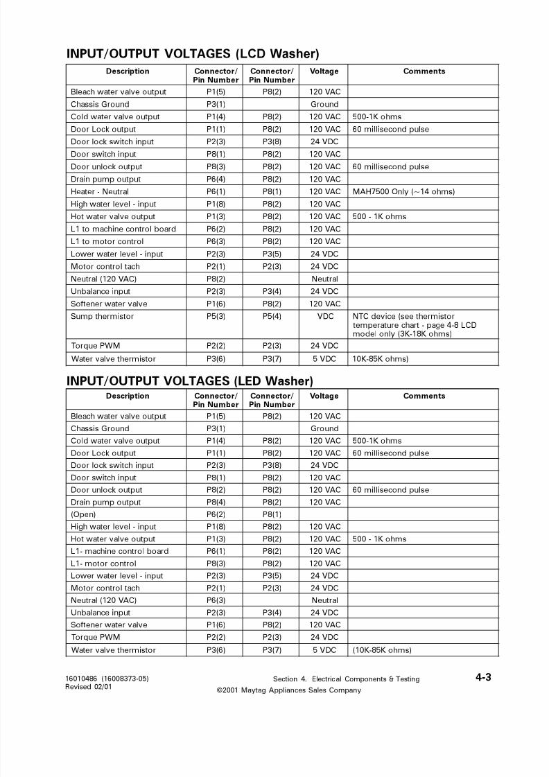
8/3/2019 Maytag MAH3000AWW Service Manual
http://slidepdf.com/reader/full/maytag-mah3000aww-service-manual 143/157
Section 4. Electrical Components & Testing 4-316010486 (16008373-05)Revised 02/01©2001 Maytag Appliances Sales Company
INPUT/OUTPUT VOLTAGES (LCD Washer)
INPUT/OUTPUT VOLTAGES (LED Washer)
noitpircseD /rotcennoCrebmuNniP
/rotcennoCrebmuNniP
egatloV stnemmoC
tuptuoevlavretawhcaelB )5(1P )2(8P CAV021
dnuorGsissahC )1(3P dnuorG
tuptuoevlavretawdloC )4(1P )2(8P CAV021 smhoK1-005
tuptuokcoLrooD )1(1P )2(8P CAV021 eslupdnocesillim06
tupnihctiwskcolrooD )3(2P )8(3P CDV42
tupnihctiwsrooD )1(8P )2(8P CAV021
tuptuokcolnurooD )3(8P )2(8P CAV021 eslupdnocesillim06
tuptuopmupniarD )4(6P )2(8P CAV021
lartueN-retaeH )1(6P )1(8P CAV021 )smho41~(ylnO0057HAM
tupni-levelretawhgiH )8(1P )2(8P CAV021
tuptuoevlavretawtoH )3(1P )2(8P CAV021 smhoK1-005
draoblortnocenihcamot1L )2(6P )2(8P CAV021
lortnocrotomot1L )3(6P )2(8P CAV021
tupni-levelretawrewoL )3(2P )5(3P CDV42
hcatlortnocrotoM )1(2P )3(2P CDV42
)CAV021(lartueN )2(8P lartueN
tupniecnalabnU )3(2P )4(3P CDV42
evlavretawrenetfoS )6(1P )2(8P CAV021
rotsimrehtpmuS )3(5P )4(5P CDV rotsimrehtees(ecivedCTNDCL8-4egap-trahcerutarepmet
)smhoK81-K3(ylnoledom
MWPeuqroT )2(2P )3(2P CDV42
rotsimrehtevlavretaW )6(3P )7(3P CDV5 )smhoK58-K01
noitpircseD /rotcennoC
rebmuNniP
/rotcennoC
rebmuNniP
egatloV stnemmoC
tuptuoevlavretawhcaelB )5(1P )2(8P CAV021
dnuorGsissahC )1(3P dnuorG
tuptuoevlavretawdloC )4(1P )2(8P CAV021 smhoK1-005
tuptuokcoLrooD )1(1P )2(8P CAV021 eslupdnocesillim06
tupnihctiwskcolrooD )3(2P )8(3P CDV42
tupnihctiwsrooD )1(8P )2(8P CAV021
tuptuokcolnurooD )2(8P )2(8P CAV021 eslupdnocesillim06
tuptuopmupniarD )4(8P )2(8P CAV021
)nepO( )2(6P )1(8P
tupni-levelretawhgiH )8(1P )2(8P CAV021
tuptuoevlavretawtoH )3(1P )2(8P CAV021 smhoK1-005
draoblortnocenihcam-1L )1(6P )2(8P CAV021
lortnocrotom-1L )3(8P )2(8P CAV021
tupni-levelretawrewoL )3(2P )5(3P CDV42
hcatlortnocrotoM )1(2P )3(2P CDV42
)CAV021(lartueN )3(6P lartueN
tupniecnalabnU )3(2P )4(3P CDV42
evlavretawrenetfoS )6(1P )2(8P CAV021
MWPeuqroT )2(2P )3(2P CDV42
rotsimrehtevlavretaW )6(3P )7(3P CDV5 )smhoK58-K01(

8/3/2019 Maytag MAH3000AWW Service Manual
http://slidepdf.com/reader/full/maytag-mah3000aww-service-manual 144/157
Section 4. Electrical Components & Testing 4-416010486 (16008373-05)Revised 02/01©2001 Maytag Appliances Sales Company
LCD Washer
LED Washer
Membrane Pad Checks
On the MAH5500B washer you can perform the Membrane Pad Check with the control
console. (See Section 2; Accessing Service Mode; Membrane Pad Check)
On both washers, you can check the membrane pads, by pulling the P7 connector from
the machine control board and locating the corresponding switch pin numbers in the
ribbon harness.
daPenarbmeM rebmuNniP rebmuNniP
emoH )3(7P )5(7P
setirovaF )4(7P )5(7P
kcaB )3(7P )6(7P
esuaP /tratS )3(7P )7(7P
ffO )4(7P )7(7P
pleH )4(7P )6(7P
daPenarbmeM rebmuNniP rebmuNniP
ydrutS /nottoC )4(7P )01(7P
eerfelknirW )5(7P )01(7P
setacileD )6(7P )01(7P
hsawdnaH )6(7P )11(7P
+esnir /hsaW )4(7P )21(7P
-esnir /hsaW )5(7P )11(7P
nipS )5(7P )21(7P
esniR )6(7P )21(7P
kciuQ )4(7P )11(7P
liosthgiL )4(7P )31(7P
lioslamroN )6(7P )31(7P
hsawyaleD )5(7P )31(7P
liosyvaeH )6(7P )41(7P
kaoserP )5(7P )6(7P
elcyCniatS )6(7P )41(7P
esniRartxE )5(7P )51(7P
tcartxexaM )6(7P )51(7P
esuap /tratS )4(7P )61(7P
ffO )5(7P )61(7P
-langiS )6(7P )51(7P
+langiS )6(7P )61(7P

8/3/2019 Maytag MAH3000AWW Service Manual
http://slidepdf.com/reader/full/maytag-mah3000aww-service-manual 145/157
Section 4. Electrical Components & Testing 4-516010486 (16008373-05)Revised 02/01©2001 Maytag Appliances Sales Company
DRIVE MOTOR
The drive motor is still a switched reluc-tance type motor. (For more information, please refer to manual 16008373, Sec-tion 4; Drive Motor.)
The new motor is a sensorless motordrive system. The word "sensorless"indicates that motor direction and speeddetection are performed electricallywithout the aid of the sending device.Meaning, the sensor was eliminated fromthe end of the motor along with the wireharness leading to the RPT connection onthe motor control board.
Motor Control Access
Slight modifications were made to the
motor control bracket and the plastic drip
shield.
Drip Shield Removal
1. Push the plastic shield on either side of
the locking tab to buckle and unlock
the shield from the motor control
bracket. (Figure 4-4)
Motor Control Board Removal
1. Pull the vertical tab forward and lift the
front of the motor control board and
slide the control forward to lift and
remove the control from the bracket.
(Figure 4-5)
MOTOR CONTROL BOARD
The motor control is able to determinethe motor's position by monitoring theactive phases in the motor. This is doneby sending pulse signals to the motor andthen timing the echo signal. By doing this,
the motor control is able to deteriminethe motor speed and direction. Thisinformation is then calculated to deter-mine the motor speed.
The motor control has a software switchin it that will turn off all power devices foras long as the main voltage is above 133VAC. Once the mains voltage dropsbelow that voltage, the power devices willbe re-enabled and the motor control willresume normal operation.
2. The motor control board bracket is
secured with two screws in front and
secured to the baseframe via a tab on
the bracket inserted into a slot in the
baseframe.
Figure 4-4
Figure 4-5

8/3/2019 Maytag MAH3000AWW Service Manual
http://slidepdf.com/reader/full/maytag-mah3000aww-service-manual 146/157
Section 4. Electrical Components & Testing 4-616010486 (16008373-05)Revised 02/01©2001 Maytag Appliances Sales Company
Motor Drive System Test
To check the system, check the board forproper output to the motor control. Thisis done by performing a board outputcheck. Then perform the Motor AndMotor Control Test.
Machine Control Board Output Test1. Place the washer into Service Mode.
(See Section 2; Accessing ServiceMode)
2. LED Washer: Access Board OutputTest and press Stain Cycle. This willsend a signal to the motor control tooperate the motor. This will test theboard relay for 120 VAC output to themotor control board. Motor will notoperate, because the door is notlocked.
LCD Washer: Access Service Testsand press system check. Touch thescreen to toggle the motor control on.This will test the board relay for 120VAC output to the motor controlboard.
Motor Phases
With the introduction of the sensorlessmotor, the Motor Phase Test is no longerrequired. If the motor experiences aphase problem, the motor will not run.
Motor & Motor Control Test1. Disconnect power to the washer.
2. Remove the front panel and pull theJP4 Connector from the motor controlboard. (Figure 4-6)
3. Reconnect the washer power cord tosupply voltage.
4. Press Help and Back function to acti-vate Service Mode.
5. LED Washer: Select Board Output Test ; close door or push dooracturator button; touch the stain cyclemembrane switch.
LCD Washer: Select System Check;close door or push door actuatorbutton: touch Toggle Motor Control On
6. The motor control will immediatelyexecute a test routine and the motorshould run, rotating the spinner at 50rpm.
7. If the motor runs, and the spinnerrotates at the proper RPM speed: theproblem lies outside of the motor andmotor control circuit. Disconnectpower to the washer and reconnectthe JP4 Interface connector to themotor control.
If the motor runs, and the spinnerdoes not rotate: Check for missing
belt.
8. If the motor does not run:a. Check the 10 amp fuse located onthe control board, either visually orwith an ohm meter. If bad, replacemotor control/wire harness assembly
completely. (Figure 4-7)
Figure 4-6

8/3/2019 Maytag MAH3000AWW Service Manual
http://slidepdf.com/reader/full/maytag-mah3000aww-service-manual 147/157
Section 4. Electrical Components & Testing 4-716010486 (16008373-05)Revised 02/01©2001 Maytag Appliances Sales Company
HEATER ASSEMBLYThe heater assembly located in the sump
area of the outer tub is only on the
MAH7500, LCD washer only. A thermistor
located in the heater assembly monitors
the water termperature in order to cycle
the heater on/off to regulate the propertemperatures.
After the wash level has been reached, the
control will turn the heater on until the
heater thermistor indicticates the tempera-
ture reaches or exceeds the target main
wash temperature. Then the control will
de-energize the heater. The heater will be
turned back on when the heater thermistor
indicates the temperature falls below the
target main wash temperature � 5°F duringthe main wash. The control will cycle the
heater off again when the temperature
reaches the target wash temperature.
The intent is to keep the temperature
between the target main wash tempera-
ture and 5°F below that. When the heater
is off, it will remain off for at least 10 sec-
onds, and when the heater is turned on, it
will remain on for at least 10 seconds. The
heater should be turned off and will re-
main off when the maximum heater on
time limit is reached (37 minutes), or the
end of the wash period is reached. The
heater will be turned off at the beginning
of bleach fill at the end of main wash. The
heater will be turned off during add fills.
Heater Will Not Turn On
1 The heater will not turn on if the door is
not closed or if there is a problem withthe door sense circuit.
Figure 4-9
9. Unplug the washer power cord and
replace motor control board connec-
tor JP4 when finished.
Figure 4-8
b. If the fuse is functioning, check the
six semiconductors on the heat sink
visually for any damage. If damaged,
replace motor control/wire harness
assembly complete.
c. If no visible damage is present,
check motor windings for any open
circuits. (See Figure 4-8 & 4-9) Re-
place motor if necessary.
Figure 4-7

8/3/2019 Maytag MAH3000AWW Service Manual
http://slidepdf.com/reader/full/maytag-mah3000aww-service-manual 148/157
Section 4. Electrical Components & Testing 4-816010486 (16008373-05)Revised 02/01©2001 Maytag Appliances Sales Company
Thermistor Temperature Chart
2 The heater will not turn on if there is a
problem with the low water level
sense. The control is required to see
the low water level go from not satis-
fied to satisfied at the beginning of the
cycle before the heater is turned on.
The heater will be turned off within 30
seconds whenever the wash water
level becomes not satisfied.
3 The heater will never turn on for more
than the maximum heater on time of
37 minutes, and will not turn on out-
side of Presoak and the main wash
period.
snoitceleSresU ,gnirepmeThsaWniaM
retaWehtnodesaB
rotsimrehTevlaV
gnisUstegraTgnitaeH
ehtnodesaBretaeHeht
rotsimrehTretaeH
)smhO.xaM-.niM( )smhO.xaM /.niM(
htiw-hsawdloC)a
detcelesrevasygrene
Cº81 /Fº56
)smhoK27-K56(gnitaeHoN
htiw-hsawdloC)b
detceles-edrevasygrene
Cº81 /Fº56ottaeH
)smhoK8.61-K3.51(
htiw-hsawmraW)c
detcelesrevasygrene
Cº5.04 /Fº501
)smhoK03-K02(gnitaeHoN
ygrenehtiw-mraW)d
detceles-edrevas
Cº14 /Fº501ottaeH
)smhoK6.6-K2.6(
ygrenehtiw-hsawtoH)edetcelesrevas
retawtoH gnitaeHoN
ygrenehtiw-hsawtoH)f
detceles-edrevas
Cº45 /Fº031ottaeH
)smhoK1.4-K9.3(

8/3/2019 Maytag MAH3000AWW Service Manual
http://slidepdf.com/reader/full/maytag-mah3000aww-service-manual 149/157
5-116010486 (16008373-05)
Revised 10/00
Section 5. Teardown & Wiring Information
©2001 Maytag Appliances Sales Company
SECTION 5. TEARDOWN & WIRING INFORMATION
Warning - Always shut off
electrical power to the unit
before beginning any ser-
vice repair procedures.
The replacement console assembly consists
of the console, medallion and membrane
pad.
CONSOLE REMOVAL
1. Disconnect power to the unit.
2. Remove the four screws securing the
console to the rear cover plate.
Figure 5-1
3. Lay a drop cloth across the top cover
of the washer.
4. Grasp the top of the console and
gently rock the top of the console
forward away from the rear console
back. Note the hooked tabs on bottom
of the console, which engage the slots
in the top cover.
Figure 5-2
MICROPROCESSOR BOARD REMOVAL
1. Disconnect power to the washer.
2. Remove the console assembly.
3. Carefully remove the membrane pad
harness and other wires from the mi-
croprocessor board.
Figure 5-3
LCD MODEL
Figure 5-4LED MODEL
5. For reinstallation, reverse the aforemen-
tioned steps.

8/3/2019 Maytag MAH3000AWW Service Manual
http://slidepdf.com/reader/full/maytag-mah3000aww-service-manual 150/157
5-216010486 (16008373-05)
Revised 10/00
Section 5. Teardown & Wiring Information
©2001 Maytag Appliances Sales Company
4. Remove the four mounting screws
securing the board to the console.
5. Remove the board from the console.
6. Note: To avoid the potential for acci-
dental static discharge damage to the
replacement board, you must be
properly grounded prior to handling
the board. This can be accomplished
by using a special grounded strap tied
on your wrist and grounded to the
product, or simply touching a
grounded source to discharge any
static charge build up on your person.
7. Insert the replacement board into the
console and secure the mountingbracket to the console.
8. Reattach wire harnesses and mem-
brane pad harness to the replacement
machine control board.
CONSOLE COVER PLUG
The cover plug inserts into the rear of the
console to fill a cavity void in the console.
The plug is secured to the console via a
console screw mounted directly behind it.
The cover plug simply fills a void area inthe console for cosmetic purposes only.
Figure 5-5
CABINET ASSEMBLY
The overall cabinet assembly design is
identical to the MAH4000 washer, except
for the revised door lock mechanism,
door latch hoop and front shroud. for
simplicity reasons, we will address onlythe exceptions in this chapter.
DOOR LATCH HOOP
The latch hoop was redesigned, eliminat-
ing the latch hoop support and spring.
REMOVAL
1. Remove the door assembly from the
washer.
2. Dissassemble the door assembly by
removing the outer door panel.
3. Locate the locking tab on the door
latch hoop and pry the tab up.
4. Squeeze the side tabs to disengage
the locating pins on the sides of thelatch hoop from the door liner.
5. Reinstallation is a reversal of the
aforementioned steps.
Figure 5-6

8/3/2019 Maytag MAH3000AWW Service Manual
http://slidepdf.com/reader/full/maytag-mah3000aww-service-manual 151/157
5-316010486 (16008373-05)
Revised 10/00
Section 5. Teardown & Wiring Information
©2001 Maytag Appliances Sales Company
DOOR LOCK MECHANISM
The door lock mechanism is now locked
and unlocked via solenoids, resulting in
faster locking and unlocking of the washer
door. The mechanism is a non-repairable
assembly and must be replaced as anassembly.
Figure 5-7
DoorLock/UnlockSolenoid
EmergencyCord
MechanicalOpener
CamSupport
Door Open/ClosedSwitchDoor Lock
Spring
RotatingCam
Lamp Socket& Lamp
Door Actuator
Door Lock/Unlock
Switch
LockingLever
SolenoidPush-Rod
DOOR LOCK MECHANISM
An Emergency Access Cord is available
and is accessible by removing the dis-
penser bezel. The nylon cord is located
and pulled in a direction away from the
lock area. The cord is attached to the
mechanical opener. When the cord is
pulled, the opener will pivot and push the
locking lever into the open positon.
Removal
1. Disconnect power to the washer.
2. Remove the front panel, dispenser
bezel and lift the top cover to expose
the door lock assembly.
3. Remove the individual wire harnesses from the assembly and the two mount-
ing screws.
4. Roll the top of the door lock assembly
forward and lift from the front shroud
assembly. Figure 5-8

8/3/2019 Maytag MAH3000AWW Service Manual
http://slidepdf.com/reader/full/maytag-mah3000aww-service-manual 152/157
5-416010486 (16008373-05)
Revised 10/00
Section 5. Teardown & Wiring Information
©2001 Maytag Appliances Sales Company
REAR ACCESS PANEL
Removal of the access panel gains access to
the rear components of the washer
(Figure 5-9).
Figure 5-9
WATER SYSTEM COMPONENTS
WATER VALVE
The water valve is accessible from the
front of the machine. The flow rate of the
valve is 4 gpm.
Removal
1. Discontinue power and water to the
machine.
2. Remove the front panel and lift the topcover.
3. Remove the wire harness connections
to the water valve solenoids.
4. Loosen and remove the hose clamps
on the inlet hoses leading away from
the water valve.
5. Locate and loosen the valve mounting
screw by turning the screw at least
three full turns.
NOTE: The mounting screw serves as a
locating pin to hold the valve in position
on the mounting bracket. By partially removing the screw, the water valve can
now be slid to the left and removed from
the bracket (Figure 5-10).
6. Carefully lift the valve with the inlet
hoses attached and direct the inlet
hoses through the openings in the valve
mounting bracket.
7. The hoses can be crimped or the water
shut off at the faucets. Place a towelbelow the valve and remove the inlet
hoses from the water valve.
8. To reinstall, reverse the aforementioned
procedure.
PRESSURE SWITCH
The pressure switch was relocated from
the console and mounted to a bracketextension molded as part of the pump
assembly. A vertical outlet on the pump
has a rubber cap positioned over the outlet
with a spout and is clamped into position.
The nipple of the pressure switch is in-
serted into the rubber spout. Pressuriza-
tion in the vertical outlet of the pump
actuates the pressure switch and deter-
mines proper fill levels.
Warning - Always shut off
electrical power to the unit
before beginning any ser-
vice repair procedures.

8/3/2019 Maytag MAH3000AWW Service Manual
http://slidepdf.com/reader/full/maytag-mah3000aww-service-manual 153/157
5-516010486 (16008373-05)
Revised 10/00
Section 5. Teardown & Wiring Information
©2001 Maytag Appliances Sales Company
REMOVAL
1. Remove the rear access panel or the
front panel to access the pressure
switch.
2. Place a towel beneath the pump.
3. Remove the plastic bag covering the
pressure switch. Press in the locking
tabs on the back of the pressure switch
and pivot the pressure switch off the
pump bracket.
4. Grasp the pressure switch and lift the
nipple of the pressure switch from the
pump cap.
REINSTALLATION
1. Reverse the aforementioned steps 1-4.
2. IMPORTANT: Reposition the plastic bag
back onto the pressure switch.
PUMP ASSEMBLY
The pump is rated at 80 watts and mounts
identically to the pump used in the
MAH3000 washer. The pressure switch
mounting bracket is a molded part of the
pump housing. For removal instructions,
see page 6-4 in the 16008373 manual.
HEATER ASSEMBLY
The 1000 watt heater is located in the tub
cover below the door openning and above
the sump area of the washer. A thermistor
on the heater regulates the temperature of
the heater to maintain proper water tem-
perature when selected. The heater is
secured to the tub cover by means of
rubber compression. An inner mounting
plate is located opposite of the external
mounting plate with a layer of rubber
between. When the nut is secured, the
rubber is compressed and expands to seal
the heater entry hole in the tub cover.
Heater resistance is 14 ohms.
Figure 5-11
Figure 5-12
Figure 5-13

8/3/2019 Maytag MAH3000AWW Service Manual
http://slidepdf.com/reader/full/maytag-mah3000aww-service-manual 154/157
5-616010486 (16008373-05)
Revised 10/00
Section 5. Teardown & Wiring Information
©2001 Maytag Appliances Sales Company
REMOVAL
1. Disconnect power to the washer.
2. Remove the wires leading to the heater
assembly.
3. Locate the mounting nut and loosen the
nut by turning the nut in a counter
clockwise direction. This will
uncompress the rubber.
4. Carefully remove the heater assembly
from the tub cover. (If the heater has
been in place for a period of time, the
rubber may have taken a set. Then a
complete tub cover removal would be
deemed necessary to push the heaterassembly out of the tub cover.)
Thermistor Removal
The thermistor is press fitted into the
rubber seal of the heater. To remove,
simply push the thermistor out and reinsertthe replacement thermistor.
SUMP COVER
The sump cover is located in the lower rear
area of the outer tub assembly, directly
above the sump area and the drain outlet.
The purpose of the sump cover is to cap-
ture the detergent dispensed into the top
dispenser. By capturing the detergent, the
washer can provide a better mix of water
and detergent in the wash water. During
normal operation, the sump cover is
flushed of detergent during the wash cycle.
REMOVAL
1. Remove the front panel, tub cover and
the spinner.
2. Remove the mounting screw securing
the cover to the outer tub.
3. Lift the front of the sump cover anddisengage from rear lip of outer tub.
Figure 5-14
Figure 5-16
Figure 5-15

8/3/2019 Maytag MAH3000AWW Service Manual
http://slidepdf.com/reader/full/maytag-mah3000aww-service-manual 155/157
5-716010486 (16008373-05)
Revised 10/00
Section 5. Teardown & Wiring Information
©2001 Maytag Appliances Sales Company
WIRING INFORMATION
Please refer to the technical schematic packed in the control console in the washer for up to
date wiring information for the product your are servicing. The schematics on the following
pages are only a general reference at the time this manual was printed.
MAH5500B

8/3/2019 Maytag MAH3000AWW Service Manual
http://slidepdf.com/reader/full/maytag-mah3000aww-service-manual 156/157
5-816010486 (16008373-05)
Revised 10/00
Section 5. Teardown & Wiring Information
©2001 Maytag Appliances Sales Company
MAH7500

8/3/2019 Maytag MAH3000AWW Service Manual
http://slidepdf.com/reader/full/maytag-mah3000aww-service-manual 157/157