MAXO + A MAXO + AE MaxOThe MAXO 2 + Analyzer is designed for medical oxygen delivery equipment and...
21
OPERATING MANUAL & INSTRUCTIONS FOR USE R217M42 Rev. M MaxO 2 + ® MAXO 2 ® + A MAXO 2 ® + AE
Transcript of MAXO + A MAXO + AE MaxOThe MAXO 2 + Analyzer is designed for medical oxygen delivery equipment and...

O P E R A T I N G M A N U A L & I N S T R U C T I O N S F O R U S E
R217M42 Rev. M
MaxO2+®
MAXO2®+ A
MAXO2®+ AE

II
Maxtec TEL (800) 748.5355 2305 South 1070 West FAX (801) 270.5590 Salt Lake City, Utah 84119 email: [email protected] USA website: www.maxtec.com
ClassificationProtection against electric shock: Internally powered equipment.Protection against water: IPX1Mode of Operation: Continuous
Do not throw away. Dispose of properly in accordance with local regulations.
WARRANTYThe MAXO2+ Analyzer is designed for medical oxygen delivery equipment and systems. Under normal operating conditions, Maxtec warrants the MAXO2+ Analyzer to be free from defects of workmanship or materials for a period of 2-years from the date of shipment from Maxtec, provided that the unit is properly operated and maintained in accordance with Maxtec’s operating instructions. Based on Maxtec product evaluation, Maxtec’s sole obligation under the foregoing warranty is limited to making replacements, repairs, or issuing credit for equipment found to be defective. This warranty extends only to the buyer purchasing the equipment directly from Maxtec or through Maxtec ‘s designated distributors and agents as new equipment.
Maxtec warrants MAXO2+ oxygen sensor in the MAXO2+ Analyzer to be free from defects in material and workmanship for a period of 2-years from Maxtec’s date of shipment in a MAXO2+ unit. Should a sensor fail prematurely, the replacement sensor is warranted for the remainder of the original sensor warranty period.
Routine maintenance items, such as batteries, are excluded from warranty. Maxtec and any other subsidiaries shall not be liable to the purchaser or other persons for incidental or consequential damages or equipment that has been subject to abuse, misuse, mis-application, alteration, negligence or accident.
These warranties are exclusive and in lieu of all other warranties, expressed or implied, including warranty of merchantability and fitness for a particular purpose.
866.4.Maxtec www.maxtec.com

PREFACE
This manual describes the function, operation and maintenance of the MAXO2+ hand-held oxygen analyzer. A member of Maxtec’s MAXO2 analyzer line of oxy-gen analyzers and monitors, the MAXO2+ utilizes the MAX-250+ oxygen sensor and is engineered for long life, maximum reliability and stable perfmance.
NOTE: In order to obtain optimum performance from your MAXO2+ analyzer, all operation and maintenance must be performed in accordance with this manual. Please read the manual thoroughly before using the analyzer and do not attempt any repair or procedure that is not described herein. Maxtec cannot warrant any damage resulting from misuse, unauthorized repair or improper maintenance of the instrument.
Thank YouThank you for your purchase of a Maxtec MAXO2+ oxygen analyzer. We appreciate the time and energy you invest in selecting the equipment best suited to your needs. As exchange, we are supplying you with a reliable, high-quality instrument that, with proper care and operation, will provide you with years of exceptional service. We also encourage your comments or suggestions as to how our equipment, in any way, can better serve your needs. Please feel free to write, FAX or e-mail us at the address on page ii of this manual c/o the Maxtec Marketing Department. Please visit our website www.maxtec.com for more information on our products and services.
WARNINGS
Never allow an excess length of tubing, lanyard, or sensor cable near a person’s head or neck, which may result in strangulation.
Before use, all individuals who will be using the MAXO2+ must become thoroughly familiar with the information contained in this Operation Manual. Strict adherence to the operating instructions is necessary for safe, effective product performance. This product will perform only as designed if installed and operated in accordance with the manufacturer’s operating instructions.
Use only genuine Maxtec accessories and replacement parts. Failure to do so may seriously impair the analyzer’s performance. Repair or alteration of the MAXO2+ beyond the scope of the maintenance instructions, or by anyone other than an authorized Maxtec service person, could cause the product to fail to per-form as designed.
Calibrate the MAXO2+ weekly when in operation, or if environmental conditions change significantly. (ie. Elevation, Temperature, Pressure, Humidity — refer to Section 4.0 of this manual).
III
!
866.4.Maxtec www.maxtec.com

IV
Use of the MAXO2+ near devices that generate electrical fields may cause erratic readings.
If the MAXO2+ is ever exposed to liquids (from spills or immersion) or to any other physical abuse, turn the instrument OFF and then ON. This will allow the unit to go through its self test to assure everything is operating correctly. You may need to allow the sensor time to dry out.
Never immerse or expose the MAXO2+ (including sensor) to high temperatures (>70°C). Never expose the device to pressure, irradiation vacuum, steam, or chemicals.
NOTE: Replace the batteries with recognized high quality AA Alkaline or Lithium batteries.
NOTE: If the unit is going to be stored (not in use for 1 month), we recommend that you remove the batteries to protect the unit from potential battery leakage.
FAILURE TO COMPLY WITH THESE WARNINGS AND CAUTIONS COULD RESULT IN INSTRUMENT DAMAGE AND POSSIBLY JEOPARDIZE THE WELL BEING OF THE USER.
866.4.Maxtec www.maxtec.com
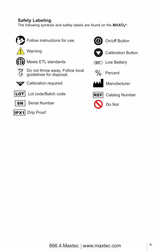
Safety LabelingThe following symbols and safety labels are found on the MAXO2+:
V
CAL
BAT
Warning
On/off Button
Calibration Button
Low Battery
Percent
Meets ETL standards
Do not throw away. Follow local guidelines for disposal.
Calibration required
%
LOT
SN
IPX1
Lot code/Batch code
Serial Number
Drip Proof
REF Catalog Number
Manufacturer
Follow instructions for use.
Do Not
!
866.4.Maxtec www.maxtec.com

VI
TABLE OF CONTENTS
Classification . . . . . . . . . . . . . . . . . . . . . . . . . . . . . . . . . . . . . . . . . . . . . . . . . . . . . . . . . . . . . . . . . . . . .iiWarranty . . . . . . . . . . . . . . . . . . . . . . . . . . . . . . . . . . . . . . . . . . . . . . . . . . . . . . . . . . . . . . . . . . . . . . . .iiWarnings . . . . . . . . . . . . . . . . . . . . . . . . . . . . . . . . . . . . . . . . . . . . . . . . . . . . . . . . . . . . . . . . . . . . . . . iiiSafety Symbols . . . . . . . . . . . . . . . . . . . . . . . . . . . . . . . . . . . . . . . . . . . . . . . . . . . . . . . . . . . . . . . . . . .v 1.0 SYSTEM OVERVIEW . . . . . . . . . . . . . . . . . . . . . . . . . . . . . . . . . . . . . . . . . . . . . . . . . . . . . . . . . .1
1.1 Base Unit Description . . . . . . . . . . . . . . . . . . . . . . . . . . . . . . . . . . . . . . . . . . . . . . . . . . . . . .1 1.2 Component Identification . . . . . . . . . . . . . . . . . . . . . . . . . . . . . . . . . . . . . . . . . . . . . . . . . . . .2 1.3 Component Description . . . . . . . . . . . . . . . . . . . . . . . . . . . . . . . . . . . . . . . . . . . . . . . . . . . . .2 1.4 MAX-250 Oxygen Sensor . . . . . . . . . . . . . . . . . . . . . . . . . . . . . . . . . . . . . . . . . . . . . . . . . . .3
2.0 OPERATING INSTRUCTIONS . . . . . . . . . . . . . . . . . . . . . . . . . . . . . . . . . . . . . . . . . . . . . . . . . . .3
2.1 Getting Started. . . . . . . . . . . . . . . . . . . . . . . . . . . . . . . . . . . . . . . . . . . . . . . . . . . . . . . . . . . .3
2.1.1 Protect Tape . . . . . . . . . . . . . . . . . . . . . . . . . . . . . . . . . . . . . . . . . . . . . . . . . . . . . . . .3 2.1.2 Automatic Calibration . . . . . . . . . . . . . . . . . . . . . . . . . . . . . . . . . . . . . . . . . . . . . . . . .3
2.2 Calibrating the MAXO2+ Oxygen Analyzer . . . . . . . . . . . . . . . . . . . . . . . . . . . . . . . . . . . . . . .4
2.3 Operation with OxyKnob Adapter. . . . . . . . . . . . . . . . . . . . . . . . . . . . . . . . . . . . . . . . . . . . . .5 2.4 Operation with BC Adapter . . . . . . . . . . . . . . . . . . . . . . . . . . . . . . . . . . . . . . . . . . . . . . . . . .6
3.0 GAS SAMPLE OPTIONS . . . . . . . . . . . . . . . . . . . . . . . . . . . . . . . . . . . . . . . . . . . . . . . . . . . . . . .7
4.0 FACTORS INFLUENCING ACCURATE READINGS. . . . . . . . . . . . . . . . . . . . . . . . . . . . . . . . . .8
4.1 Elevation Changes. . . . . . . . . . . . . . . . . . . . . . . . . . . . . . . . . . . . . . . . . . . . . . . . . . . . . . . . .8 4.2 Temperature Effects. . . . . . . . . . . . . . . . . . . . . . . . . . . . . . . . . . . . . . . . . . . . . . . . . . . . . . . .8 4.3 Pressure Effects. . . . . . . . . . . . . . . . . . . . . . . . . . . . . . . . . . . . . . . . . . . . . . . . . . . . . . . . . . .8 4.4 Humidity Effects . . . . . . . . . . . . . . . . . . . . . . . . . . . . . . . . . . . . . . . . . . . . . . . . . . . . . . . . . . .8
5.0 CALIBRATION ERRORS AND ERROR CODES . . . . . . . . . . . . . . . . . . . . . . . . . . . . . . . . . . . . .9
6.0 CHANGING THE BATTERIES . . . . . . . . . . . . . . . . . . . . . . . . . . . . . . . . . . . . . . . . . . . . . . . . . .10
7.0 CHANGING THE OXYGEN SENSOR. . . . . . . . . . . . . . . . . . . . . . . . . . . . . . . . . . . . . . . . . . . . .11
7.1 MAXO2+A Model . . . . . . . . . . . . . . . . . . . . . . . . . . . . . . . . . . . . . . . . . . . . . . . . . . . . . . . . .11 7.2 MAXO2+AE Model . . . . . . . . . . . . . . . . . . . . . . . . . . . . . . . . . . . . . . . . . . . . . . . . . . . . . . . .12
8.0 CLEANING AND MAINTENANCE . . . . . . . . . . . . . . . . . . . . . . . . . . . . . . . . . . . . . . . . . . . . . . .12
9.0 SPECIFICATIONS . . . . . . . . . . . . . . . . . . . . . . . . . . . . . . . . . . . . . . . . . . . . . . . . . . . . . . . . . . . .13
9.1 Base Unit Specifications . . . . . . . . . . . . . . . . . . . . . . . . . . . . . . . . . . . . . . . . . . . . . . . . . . .13 9.2 Sensor Specifications. . . . . . . . . . . . . . . . . . . . . . . . . . . . . . . . . . . . . . . . . . . . . . . . . . . . . .14
10.0 MAXO2+ SPARE PARTS AND ACCESSORIES . . . . . . . . . . . . . . . . . . . . . . . . . . . . . . . . . . . . .14
10.1 Included With Your Unit . . . . . . . . . . . . . . . . . . . . . . . . . . . . . . . . . . . . . . . . . . . . . . . . . . . .14 10.2 Standard Replacement Parts. . . . . . . . . . . . . . . . . . . . . . . . . . . . . . . . . . . . . . . . . . . . . . . .14 10.3 Optional Accessories . . . . . . . . . . . . . . . . . . . . . . . . . . . . . . . . . . . . . . . . . . . . . . . . . . . . . .14
10.3.1 Optional Adapters. . . . . . . . . . . . . . . . . . . . . . . . . . . . . . . . . . . . . . . . . . . . . . . . . . .14 10.3.2 Mounting Options . . . . . . . . . . . . . . . . . . . . . . . . . . . . . . . . . . . . . . . . . . . . . . . . . . .15 10.3.3 Carrying Options. . . . . . . . . . . . . . . . . . . . . . . . . . . . . . . . . . . . . . . . . . . . . . . . . . . .15
866.4.Maxtec www.maxtec.com
1.0 SYSTEM OVERVIEW
1.1 Base Unit Description
The MAXO2+ analyzer provides unparalleled performance and reliability due to an advanced design that includes the following features and oper-ational benefits.
• Extra-life oxygen sensor of approximately 1,500,000 O2 percent hours (2-year warranty)
• Durable, compact design that permits comfortable, hand-held operation and easy to clean.
• Operation using only two AA Alkaline batteries (2 x 1.5 Volts) for approximately 5000 hours of performance with continuous use. For extra extended long life, two AA Lithium batteries may be used.
• Oxygen-specific, galvanic sensor that achieves 90% of final value in approximately 15 seconds at room temperature.
• Large, easy-to-read, 3 1/2-digit LCD display for readings in the 0-100% range.
• Simple operation and easy one-key calibration.
• Self-diagnostic check of analog and microprocessor circuitry.
• Low battery indication.
• Calibration reminder timer that alerts the operator, using a calibration icon on the LCD display, to perform a unit calibration.
1 866.4.Maxtec www.maxtec.com

2
1
LCD Display
2
3
4
5
6
FIGURE 1
Keypad
Sample Inlet Connection
1.2 Component Identification
1.3 Component Description 1. 3 1/2-Digit Display - The 3 1/2 digit liquid crystal display (LCD)
provides direct readout of oxygen concentrations in the range of 0 - 105.0% (100.1% - 105.0% used for calibration determination purposes). The digits also display error codes and calibration codes as necessary.
2. Low Battery Indicator - The low battery indicator is located at the top of the display and is only activated when the voltage on the batteries is below a normal operating level.
3. “%” symbol - The “%” sign is located to the right of the concentration number and is present during normal operation.
4. Calibration symbol - The calibration symbol is located at the bottom of the display and is timed to activate when a calibration is necessary.
5. ON/OFF Key - This key is used to turn the device on or off.
6. Calibration Key - This key is used to calibrate the device. Holding the key for more than three seconds will force the device to enter a
calibration mode.
CAUTION: The device will assume a percent oxygen concentration when calibrating. Be sure to apply 100% oxygen, or ambient air concentration to the device during calibration or the device will not calibrate correctly.
Sample Inlet Connection
This is the port at which the device is connected to determine oxygen concen-tration.
CAL
866.4.Maxtec www.maxtec.com

1.4 MAX-250+ Oxygen Sensor
The MAX-250+ oxygen sensor offers stability and extra life.The MAX-250+ is a galvanic, partial pressure sensor that is specific to oxygen. It consists of two electrodes (a cathode and an anode), a teflon membrane and an electrolyte. Oxygen diffuses through the teflon membrane and immediately reacts at a gold cathode. Concurrently, oxidation occurs electrochemically at the lead anode, generating an electrical current and providing a voltage output. Electrodes are immersed in a unique gelled weak acid electrolyte which is responsible for the sensors long life and motion insensitive characteristic. Since the sensor is specific to oxygen, the current generated is proportional to the amount of oxygen present in the sample gas. When no oxygen is present, there is no electrochemical reaction and there-fore, negligible current is produced. In this sense, the sensor is self-zeroing.
CAUTION: The Maxtec MAX-250+ oxygen sensor is a sealed device containing a mild acid electrolyte, lead (Pb), and lead acetate. Lead and lead acetate are hazardous waste constituents and should be disposed of properly, or returned to Maxtec for proper disposal or recovery.
CAUTION: Do not immerse the sensor in any cleaning solution, autoclave or expose the sensor to high temperatures.
CAUTION: Dropping sensor can adversely affect its performance. Do not throw away. Dispose of properly in accordance with local regulations.
2.0 OPERATING INSTRUCTIONS
2.1 Getting Started
2.1.1 Protect Tape
Prior to turning on the unit, a protective film covering the threaded sensor face must be removed. After removing the film, wait approximately 20 minutes for the sensor to reach equilibrium.
2.1.2 Automatic Calibration
After the unit is turned on it will automatically calibrate to room air. The display should be stable and reading 20.9%. To check the oxygen concen-tration of a sample gas: (after the unit has been calibrated).
3 866.4.Maxtec www.maxtec.com

4
1. Connect the Tygon tubing to the bottom of the analyzer by threading the barbed adapter onto the oxygen sensor. (figure 2)
2. Attach the other end of the sample hose to the sample gas source and initiate flow of the sample to the unit at a rate of 1-10 liters per minute (2 liters per minute is recommended).
3. Using the “ON/OFF” key, make sure the unit is in the power “ON” mode.
4. Allow the oxygen reading to stabilize. This will normally take about 30 seconds or more.
2.2 Calibrating the MAXO2+ Oxygen Analyzer
The MAXO2+ Analyzer should be calibrated upon initial power-up. Thereafter, Maxtec® recommends calibration on a weekly basis. To serve as a reminder, a one week timer is started with each new calibration. At the end of one week a reminder icon “ ” will appear on the bottom of the LCD. Calibration is recommended if the user is unsure when the last calibration procedure was
performed, or if the measurement value is in question.Start calibration by pressing the Calibration button for more than 3 seconds. The MAXO2+ will automatically detect if you are calibrating with 100% or 20.9% oxygen (normal air). Do not attempt to calibrate to any other concentration.
100% O2 verification, new calibration is required when:
• The measured O2 percentage in 100% O2 is below 99.0% O2. • The measured O2 percentage in 100% O2 is above 101.0% O2. • The CAL reminder Icon is blinking at the bottom of the LCD. • If you are unsure about the displayed O2 percentage. (see Factors
influencing accurate readings.)
Compressed air (20.9% O2), new calibration is required when:
• The measured O2 percentage in 20.9% O2 is below 19.9% O2. • The measured O2 percentage in 20.9% O2 is above 21.9% O2. • The CAL reminder Icon is blinking at the bottom of the LCD. • If you are unsure about the displayed O2 percentage.
(see Factors influencing accurate readings.)
Calibrate with the same type of circuit and flow that you will use when taking your readings.
FIGURE 2
CAL
866.4.Maxtec www.maxtec.com

5
A simple calibration may be made with the sensor open to static Ambient air. For optimum accuracy Maxtec recommends that the Sensor be placed in a closed loop circuit where gas flow is moving across the sensor in a controlled manner.
2.3 Operation with Oxyknob Adapter (refer to figure below)1. Attach the Oxyknob adaptor to the threaded sensor of your Maxtec
Analyzer.
2. Hand tighten until sensor o-ring seals against the Oxyknob.
3. Slowly crack open the tank. Listen for a slight hissing sound.
4. Hold the Oxyknob up to the outlet of the tank.
5. Align the small hole in the bottom or side of the Oxyknob to the hole in the outlet of the tank.
6. Hold the analyzer in place untile the reading has stabilized on the analyzer display. (about 15 seconds or less)
7. Remove Oxyknob after reading and close valve on the tank.
WARNING:
High gas pressures may cause damage to oxygen sensor and result in incor-rect readings. Turn down the tank valve as much as possible to avoid sensor damage.
Do not cover the larger holes on the Oxyknob.
Cold gas exiting a pressurized tank can cause the sensor reading to drift if exposed for an extended period of time. Allow sensor to warm between readings if necessary.
!
866.4.Maxtec www.maxtec.com

6
2.4 Operation with Optional BC Adapter (refer to figure below)
1. Attach the included Barbed Adapter to the MAXO2+ by threading it on to the bottom of the sensor.
2. Connect the included tubing to the barbed adapter.
3. Attach the BC adapter (sold separately) to the other end of the tube.
4. Connect the inflator hose on the regulator to the BC adapter and tube.
5. If the MAXO2+ is not already turned on, do so now by pressing the analyzer “ON” button.
6. Initiate flow of nitrox to the unit to allow the gas to saturate the sensor. The BC adapter will regulate the optimum flow and pressure. Although a stable value is usually observed within 30 seconds, allow at least two minutes to ensure that the sensor is completely saturated with the gas.
7. The analyzer will now look for a stable sensor signal and a good reading. When obtained, the analyzer will display the oxygen percentage on the LCD.
FIGURE 3
Inflator Hose
Nitrox Tank
866.4.Maxtec www.maxtec.com

3.0 GAS SAMPLE OPTIONS
7 866.4.Maxtec www.maxtec.com

4.0 FACTORS INFLUENCING ACCURATE READINGS
4.1 Elevation Changes
• Changes in elevation result in a reading error of approximately 1% of reading per 250 feet.
• In general, calibration of the instrument should be performed when elevation at which the product is being used changes by more than 500 feet.
4.2 Temperature Effects
The MAXO2+ will hold calibration and read correctly within ±3% when in ther-mal equilibrium within the operating temperature range. The device must be thermally stable when calibrated and allowed to thermally stabilize afterexperiencing temperature changes before readings are accurate. For these reasons, the following is recommended:
• For best results, perform the calibration procedure at a temperature close to the temperature where analysis will occur.
• Allow adequate time for the sensor to equilibrate to a new ambient temperature.
CAUTION: “CAL Err St” may result from a sensor that has not reached thermal equilibrium.
4.3 Pressure Effects
Readings from the MAXO2+ are proportional to the partial pressure of oxy-gen. The partial pressure is equal to the concentration times the absolute pressure. Thus, the readings are proportional to the concentration if the pressure is held constant. Therefore, the following are recommended:
• Calibrate the MAXO2+ at the same pressure as the sample gas.
• If sample gases flow through tubing, use the same apparatus and flow rates when calibrating as when measuring.
• The MAXO2+ oxygen sensor has been tested at pressures up to two atmospheres absolute. Calibration or operation above this pressure is beyond the intended use.
4.4 Humidity Effects
Humidity (non-condensing) has no effect on the performance of the MAXO2+
8 866.4.Maxtec www.maxtec.com

other than diluting the gas, as long as there is no condensation. Depending on the humidity, the gas may be diluted by as much as 4%, which proportion-ally reduces the oxygen concentration. The device responds to the actual oxygen concentration rather than the dry concentration. Environments where condensation may occur are to be avoided since moisture may obstruct passage of gas to the sensing surface, resulting in erroneous readings and slower response time. For this reason, the following is recommended:
• Avoid usage in environments greater than 95% relative humidity.
HELPFUL HINT: Dry sensor by lightly shaking moisture out, or flow a dry gas at two liters per minute across the sensor membrane.
5.0 CALIBRATION ERRORS AND ERROR CODES
The MAXO2+ analyzers have a self test feature built into the software to detect faulty calibrations, oxygen sensor failures, and low operating voltage. These are listed below, and include possible actions to take, if an error code occurs.
E02: No sensor attachedMAXO2+A: Open unit and disconnect and reconnect sensor. Unit should perform an auto calibration and should read 20.9%. If not, contact Maxtec Customer Service for possible sensor replacement.
MAXO2+AE: Disconnect and reconnect external sensor. Unit should perform an auto calibration, and should read 20.9%. If not, contact Maxtec Customer Service for possible sensor replacement or cable replacement.
E03: No valid calibration data availableMake sure unit has reached thermal equilibrium. Press and hold the Calibration Button for three seconds to manually force a new calibration.
E04: Battery below minimum operating voltageReplace batteries.
CAL Err St: O2 Sensor reading not stableWait for displayed oxygen reading to stabilize, when calibrating the device at 100% oxygen.
Wait for unit to reach thermal equilibrium (Please note that this can take up to one half hour, if the device is stored in temperatures outside the specified operating temperature range).
CAL Err lo: Sensor voltage too lowPress and hold the Calibration Button for three seconds to manuallya new calibration. If unit repeats this error more than three times, contact Maxtec Customer Service for possible sensor replacement.
9 866.4.Maxtec www.maxtec.com
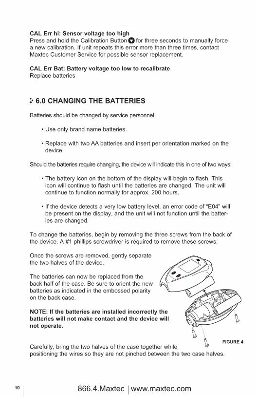
FIGURE 4
CAL Err hi: Sensor voltage too highPress and hold the Calibration Button for three seconds to manually force a new calibration. If unit repeats this error more than three times, contact Maxtec Customer Service for possible sensor replacement.
CAL Err Bat: Battery voltage too low to recalibrateReplace batteries
6.0 CHANGING THE BATTERIES
Batteries should be changed by service personnel.
• Use only brand name batteries.
• Replace with two AA batteries and insert per orientation marked on the device.
Should the batteries require changing, the device will indicate this in one of two ways:
• The battery icon on the bottom of the display will begin to flash. This icon will continue to flash until the batteries are changed. The unit will continue to function normally for approx. 200 hours.
• If the device detects a very low battery level, an error code of “E04” will be present on the display, and the unit will not function until the batter-ies are changed.
To change the batteries, begin by removing the three screws from the back of the device. A #1 phillips screwdriver is required to remove these screws.
Once the screws are removed, gently separate the two halves of the device.
The batteries can now be replaced from the back half of the case. Be sure to orient the newbatteries as indicated in the embossed polarity on the back case.
NOTE: If the batteries are installed incorrectly the batteries will not make contact and the device will not operate.
Carefully, bring the two halves of the case together while positioning the wires so they are not pinched between the two case halves.
10 866.4.Maxtec www.maxtec.com

FIGURE 4
5
The gasket separating the halves will be captured on the back case half.
Reinsert the three screws and tighten until the screws are snug. (figure 4)
The device will automatically perform a calibration and begin displaying % of oxgen.
HELPFUL HINT: If unit does not function, verify that the screws are tight to allow proper electrical connection.
HELPFUL HINT (MAXO2+ AE): Before closing the two case halves together, verify that the keyed slot on top of the coiled cable assembly is engaged on the small tab located on the back case. This is designed to position the assembly in the correct orientation and prevent it from rotating. Improper positioning could hinder the case halves from closing and prevent operation when tightening the screws.
7.0 CHANGING THE OXYGEN SENSOR
7.1 MAXO2®+A Model
Should the oxygen sensor require changing, the device will indicate this by presenting “Cal Err lo” on the display after initiating a calibration.
To change the oxygen sensor, begin by removing the three screws from the back of the device. A #1 Phillips screwdriver is required to remove these screws.
Once the screws are removed, gently separate the two halves of the device.
Disconnect the oxygen sensor from the printed circuit board by pressing the un-lock lever first and then pulling the connector out of the receptacle.
The oxygen sensor can now be replaced from the back half of the case.
HELPFUL HINT: Be sure to orient the new sensor by aligning the red arrow on the sensor with the arrow in the back case. A small tab is located on the back case that is designed to engage the sensor and pre-vent it from rotating within the case. (figure 5)NOTE: If the oxygen sensor is installed incorrectly, the case will not come back together and the unit may be damaged when the screws are reinstalled.
11 866.4.Maxtec www.maxtec.com

Note: if the new sensor has red tape over the outside, remove it and wait 30 minutes before calibrating.
Reconnect the oxygen sensor to the connector on the printed circuit board.
Carefully bring the two halves of the case together while positioning the wires to ensure they are not pinched between the two case halves. Make sure the sensor is fully inserted and in the proper orientation.
Reinsert the three screws and tighten until the screws are snug. Verify the unit operates properly.
The device will automatically perform a calibration and begin displaying % of oxygen.
7.2 MAXO2+AE ModelShould the oxygen sensor require changing, the device will indicate this by presenting “Cal Err lo” on the display.
Unthread the sensor from the cable by rotating the thumbscrew connector counterclockwise and pull the sensor from the connection.
Replace the new sensor by inserting the electrical plug from the coiled cord into the receptacle on the oxygen sensor. Rotate the thumbscrew clockwise until snug.
The device will automatically perform a calibration and begin displaying % of oxygen.
8.0 CLEANING AND MAINTENANCEStore the MAXO2+ analyzer in a temperature similar to its ambient environ-ment of daily use.
The instruction given below describes the methods to clean the instrument, sensor and its accessories:
Instrument • When cleaning or disinfecting the exterior of the MAXO2+ analyzer, take
appropriate care to prevent any solution from entering the instrument. Do not immerse unit in fluids.
Oxygen Sensor
• Clean the sensor with a cloth moistened with a 65% alcohol/water solution.
• Maxtec does not recommend use of spray disinfectants because they can contain salt, which can accumulate in the sensor membrane and impair readings.
12 866.4.Maxtec www.maxtec.com

Accessories • The threaded barbed adapter may be cleaned by washing them with a
65% alcohol/water solution (per manufacturer’s instructions). The parts must be thoroughly dry before they are used.
Because of the variability of the cleaning processes, Maxtec cannot provide specific instructions. Therefore, we highly recommend referring to the manu-facturer’s instructions on the details of method.
9.0 SPECIFICATIONS
9.1 Base Unit Specifications
Measurement Range: 0-100%Resolution: 0.1%Accuracy and Linearity: 1% of full scale at constant temperature, R.H. and
pressure when calibrated at full scale.Total Accuracy: ±3% actual oxygen level over full operating
temperature range.Response Time: 90% of final value in approximately 15 seconds at
23°C.Warm-up Time: none requiredOperating Temperature: 15°C - 40°C (59°F - 104°F)Storage Temperature: -15°C - 50°C (5°F - 122°F)Humidity: 0-95% (non-condensing)Power Requirements: 2, AA Alkaline batteries (2 x 1.5 Volts)Battery Life: approximately 5000 hours with continuous useLow Battery Indication: “BAT” icon displayed on LCDSensor Type: Maxtec MAX-250 galvanic fuel cellExpected Sensor Life: >1,500,000 O2 percent hours minimum 2-years in
typical applicationsA Model Dimensions: 3.0”(W) x 4.0”(H) x 1.5”(D) [76mm x 102mm x
38mm]A Weight: 0.4 lbs. (170g)AE Model Dimensions: 3.0”(W) x 36.0”(H) x 1.5”(D) [76mm x 914mm x
38mm] Height includes external cable length (retracted).AE Weight: 0.6 lbs. (285g)
13 866.4.Maxtec www.maxtec.com

9.2 Sensor Specifications
Type: Galvanic fuel sensor (0-100%)Life: 2-years in typical applications
10.0 MAXO2+ SPARE PARTS AND ACCESSORIES
10.1 Included With Your UnitPart Number Item R217M42 Industrial Guide and Operating InstructionsRP76P06 LanyardR207P17 Threaded Adapter with Tygon TubingR110P10-001 Flow DiverterR218P19 Oxyknob AdapterR217P35 Dovetail Bracket X
10.2 Standard Replacement Parts
Part Number Item R125P02-013 MAX-250+ Internal Oxygen SensorR125P03-004 MAX-250E External Oxygen SensorR115P85 MAX-250ESF External Oxygen SensorR217P08 GasketR217P09-002 OverlayR217P11-001 Back AssemblyR217P16-002 Front Assembly (Includes Board and LCD)R217P24 Coiled Cable AssemblyRP06P25 #4-40 Pan Head Stainless Steel Screw
10.3 Optional Accessories
10.3.1 Optional Adapters Part Number Item RP16P02 “T” Adapter (15mm I.D.) RP16P09 Scuba Pro Adapter R101P01 Flow Thru Head RP11P28 BC Adapter
X X X X X X X X
BAT
CAL
A AE
X X X X X X X X X X X X X X
14 866.4.Maxtec www.maxtec.com
10.3.2 Mounting Options (requires dovetail-R217P23) Part Number Item R103P01 M16 x 1 Maxtec Nut R205P86 Wall Mount R213P31 Swivel Mount
10.3.3 Carrying Options Part Number Item R213P02 Zipper Carrying Case with Shoulder Strap R213P56 Water Tight Carrying Case, Large (9” x 11”) R217P22 Belt Clip and Pin Assembly R217P32 Soft Case, Tight Fit Carrying Case
Repair of this equipment must be performed by a qualified service technician experienced in repair of portable hand held medical equipment.
Equipment in need of factory repair shall be sent to: Maxtec Customer Service Department 2305 South1070 West Salt Lake City, Ut 84119 (Include RMA number issued by customer service)
15 866.4.Maxtec www.maxtec.com