Maximizing Missile Flight Performance
70
03/12/22 Eugene L. Fleeman Senior Technical Advisor Georgia Institute of Techno Maximizing Missile Flight Performance
Transcript of Maximizing Missile Flight Performance

04/07/23 ELF 1
Eugene L. FleemanSenior Technical AdvisorGeorgia Institute of Technology
Maximizing Missile Flight Performance
Maximizing Missile Flight Performance

04/07/23 ELF 2
OutlineOutline
Parameters and Technologies That Drive Missile Flight Performance
Missile Flight Performance Prediction Examples of Maximizing Missile Flight Performance ( Workshop
) Summary

04/07/23 ELF 3
Parameters That Drive Missile Flight Performance
Parameters That Drive Missile Flight Performance
Nose FinenessDiameter
Propellant / Fuel
Wing Geometry / Size
Stabilizer Geometry / Size
Flight Control Geometry / Size
Length
ThrustProfile
Flight Conditions ( , M, h )

04/07/23 ELF 4
Small Diameter Missiles Have Low DragSmall Diameter Missiles Have Low Drag
10
100
1000
10000
100000
4 8 12 16 20
d, Diameter, inches
D /
CD
, Dra
g / D
rag
Coe
ffic
ient
, lb.
.
Dynamic Pressure =1,000 psf
Dynamic Pressure =5,000 psf
Dynamic Pressure =10,000 psf
Example for Rocket Baseline:
d = 8 inches = 0.667 ft
Mach 2, h = 20K ft, ( CD0 )Powered = 0.95
q = 1/2 V2 = 1/2 ( M a )2
= 1/2 ( 0.001267 ) [( 2 ) ( 1037 )]2 = 2,725 psf
D0 / CD0 = 0.785 ( 2725 ) ( 0.667 )2 = 952
D0 = 0.95 ( 952 ) = 900 lb
D = CD q SRef = 0.785 CD q d2
Note: D = drag in lb, CD = drag coefficient, q = dynamic pressure in psf, d = diameter ( reference length ) in ft
04/07/23 ELF 5
Supersonic Drag Is Driven by Nose Fineness While Subsonic Drag is Driven by Skin FrictionSupersonic Drag Is Driven by Nose Fineness
While Subsonic Drag is Driven by Skin Friction
0.01
0.1
1
10
0 1 2 3 4 5
M, Mach Number
(CD0)Body,Wave;lN / d = 0.5
(CD0)Body,Wave;lN / d = 1
(CD0)Body,Wave;lN / d = 2
(CD0)Body,Wave;lN / d = 5
(CD)Base,Coast
Example for Rocket Baseline:
( CD0 )Body, Wave ( CD0
)Body, Friction ( CD )Base
lN / d = 2.4, Ae = 11.22 in2, SRef = 50.26 in2, M = 2, h = 20K ft, q = 2725 psf, l / d = 18, l = 12 ft
( CD0 )Body, Wave = 0.14
( CD )Base Coast = 0.25 / 2 = 0.13
( CD )Base Powered = ( 1 - 0.223 ) ( 0.25 / 2 ) = 0.10
( CD0 )Body, Friction = 0.053 ( 18 ) { ( 2 ) / [( 2725 )
( 12 ) ]}0.2 = 0.14
( CD0 )Body, Coast = 0.14 + 0.13 + 0.14 = 0.41
( CD0 )Body, Powered = 0.14 + 0.10 + 0.14 = 0.38
( CD0 )Body, Wave = ( 1.59 + 1.83 / M2 ) { tan-1 [ 0.5 / ( lN / d )]}1.69, for M > 1. Based on Bonney reference, tan-1 in rad.
( CD0 )Base,Coast = 0.25 / M, if M > 1 and (CD0
)Base,Coast = ( 0.12 + 0.13 M2 ), if M < 1
( CD0 )Base,Powered = ( 1 – Ae / SRef ) ( 0.25 / M ), if M > 1 and ( CD0
)Base,Powered = ( 1 – Ae / SRef ) ( 0.12 + 0.13 M2 ), if M < 1
(CD0 )Body,Friction = 0.053 ( l / d ) [ M / ( q l )]0.2. Based on Jerger reference, turbulent boundary layer, q in psf, l in ft.
( CD0 )Body = ( CD0
)Body, Wave + ( CD0 )Base + (CD0 )Body,Friction
Note: ( CD0 )Body,Wave = body zero-lift wave drag coefficient, ( CD0
)Base = body base drag coefficient, ( CD0 )Body, Friction = body skin
friction drag coefficient, ( CD0 )Body = body zero-lift drag coefficient, lN = nose length, d = missile diameter, l = missile body length,
Ae = nozzle exit area, SRef = reference area, q = dynamic pressure, tan-1 [ 0.5 / ( lN / d )] in rad

04/07/23 ELF 6
Lifting Body Has Higher Normal ForceLifting Body Has Higher Normal Force
CN,Example NormalForce
Coefficient for l / d = 20
150
100
50
00 20 40 60 80 100
, Angle of Attack, Deg
2a
2b
a / b = 3
a / b = 2
a / b = 1
Note:If negative, CN negativeBased on slender body theory ( Pitts, et al ) and cross flow theory ( Jorgensen ) referencesExample l / d = length / diameter = 20d = 2 ( a b )1/2
= 0°
CN = [( a / b ) cos + ( b / a ) sin ] [ sin ( 2 ) cos ( / 2 ) + 2 ( l / d ) sin2 ]
CN

04/07/23 ELF 7
Large Surface Area Increases Normal Force and Maneuverability
Large Surface Area Increases Normal Force and Maneuverability
0
0.5
1
1.5
2
2.5
3
3.5
0 30 60 90
M < 1.35, based on slender wing theory + Newtonian impact theoryM = 2, based on linear wing theory + Newtonian impact theoryM = 5, based on linear wing theory + Newtonian impact theory
( CN ) W
ing S
REF
/ S W
,
Win
g N
orm
al F
orce
Coe
ffici
ent
for R
ocke
t Bas
elin
e
’ = W = + , Wing Effective Angle of Attack, Deg
( CN )Wing = [ 4sin ’ cos ’ / ( M2 – 1 )1/2 + 2 sin2’ ] ( SW / SRef ), if M > { 1 + [ 8 / ( A )]2 }1/2
( CN )Wing = [ ( A / 2) sin ’ cos ’ + 2 sin2’ ] ( SW / SRef ), if M < { 1 + [ 8 / ( A )]2 }1/2
Note: Linear wing theory applicable if M > { 1 + [ 8 / ( A )]2 }1/2, slender wing theory applicable if M < { 1 + [ 8 / ( A )]2 }1/2, A = Aspect Ratio, SW = Wing Planform Area, SRef = Reference Area
Example for Rocket Baseline
AW = 2.82
SW = 2.55 ft2
SRef = 0.349 ft2
= 13 deg, = 9 deg
M = 2
{ 1 +[ 8 / ( A )]2 }1/2 = 1.35
Since M > 1.35, use linear wing theory + Newtonian theory’ = W = + = 22( CN )Wing SRef / SW = [ 4 sin 22 cos 22 / ( 22 – 1 )1/2 + 2 sin2 22] = 1.083( CN )Wing = 1.08 ( 2.55 ) / 0.349 = 7.91

04/07/23 ELF 8
Wing Skin Friction Drag Is Larger Than Shock Wave Drag for a Thin Wing
Wing Skin Friction Drag Is Larger Than Shock Wave Drag for a Thin Wing
0
0.005
0.01
0.015
0.02
100 1000 10000
q, Dynamic Pressure, psf
M / cmac = 0.01 / ft M / cmac = 0.1 / ftM / cmac = 1 / ft M / cmac = 10 / ft
( CD0 )Wing,Friction = nW { 0.0133 [ M / ( q cmac )]0.2 } ( 2 SW / SRef ), based on Jerger, turbulent, q in psf, cmac in ft
( CDO )Wing,Wave = nW [ 2 / ( MLE
2 )]{{[( + 1 ) MLE2 ] / 2 } / ( - 1 ) {( + 1 ) / [ 2 MLE
2 – ( - 1 )]}1 / ( - 1 ) – 1 } sin2
LE cos LE tmac b / SRef , based on Newtonian impact theory ( CDO
)Wing = ( CDO )Wing,Wave + ( CDO
)Wing,Friction nW = number of wings ( cruciform = 2 )
q = dynamic pressure in psf
cmac = length of mean aero chord in ft
= Specific heat ratio = 1.4
MLE = M cos LE = Mach number leading edge
LE = leading edge section total angle
LE = leading edge sweep angle
tmac = max thickness of mac
b = spanExample for Rocket Baseline Wing:
nW = 2, h = 20K ft ( q = 2,725 psf ), cmac = 1.108 ft, SRef = 50.26 in2, SW = 367 in2, LE = 10.01 deg, LE = 45 deg, tmac = 0.585 in, b = 32.2 in, M = 2 ( MLE
= 1.41 )
( CDO )Wing,Friction SRef / [ nW SW ] = 2 {( 0.0133 ) { 2 /
[( 2725 ) ( 1.108 )]}0.2 } = 0.00615
( CD0 )Wing,Friction = 0.00615 ( 2 ) ( 367 ) / 50.26 = 0.090
( CD0 )Wing,Wave = 0.024
( CDO )Wing = 0.024 + 0.090 = 0.11
( CD
0 ) Win
g,Fr
ictio
n SR
ef /
( nW S
W )

04/07/23 ELF 9
Relaxed Static Margin Allows Higher Trim Angle of Attack and Higher Normal Force
Relaxed Static Margin Allows Higher Trim Angle of Attack and Higher Normal Force
CN, Trim, Trimmed Normal Force Coefficient of Rocket Baseline
0 4 8 12 16 20 24
16
12
8
4
0
TrimTrim Angle of Attack, Deg
Note: Rocket Baseline
XCG = 75.7 in.Mach 2
( + )Max = 21.8 Deg, ( CNTrim )Max
/ = 0.75, ( Static Margin = 0.88 Diam )
/ = 1.5, ( SM = 0.43 Diam )
/ = , ( SM = 0 )

04/07/23 ELF 10
Scramjet
High Specific Impulse Provides Higher Thrust and Reduces Fuel Consumption
High Specific Impulse Provides Higher Thrust and Reduces Fuel Consumption
Turbojet
Ramjet
Solid Rocket
4,000
3,000
2,000
1,000
0
Thru
st /
( Fue
l Flo
w R
ate
), Sp
ecifi
cIm
puls
e, I SP
, Sec
onds
0 2 4 6 8 10 12
Mach Number
Ducted Rocket

04/07/23 ELF 11
Solid Rockets Have High Acceleration CapabilitySolid Rockets Have High Acceleration Capability
1,000
100
10
10 1 2 3 4 5
RamjetTMax = ( / 4 ) d2 V
2 [( Ve / V ) - 1 ]
Solid RocketTMax = 2 PC At = m
. Ve
M, Mach Number
( T /
W ) M
ax ,
( Thr
ust /
Wei
ght )
Max
,
Note:
PC = Chamber pressure, At = Nozzle throat area, m. = Mass flow rate
d = Diameter, = Free stream density, V = Free stream velocity,
Ve = Nozzle exit velocity ( Turbojet: Ve ~ 2,000 ft / sec, Ramjet: Ve ~ 4,500 ft / sec, Rocket: Ve ~ 6,000 ft / sec )
TurbojetTMax = ( / 4 ) d2 V
2 [( Ve / V ) - 1 ]
04/07/23 ELF 12
High Thrust for a Ramjet Occurs from Mach 3 to 5 with High Combustion Temperature
High Thrust for a Ramjet Occurs from Mach 3 to 5 with High Combustion Temperature
0
5
10
15
20
25
0 1 2 3 4 5
M, Mach Number
T / [
PH
I ( p
0 ) (
A3
) ], N
ondi
mim
ensi
onal
Thr
ust i
f Spe
cific
H
eat R
atio
= 1
.29
T4 / T0 = 3 T4 / T0 = 5 T4 / T0 = 10 T4 / T0 = 15
T / ( p0 A3 ) = M02 {{[ T4 / T0 ] / { 1 + [( - 1 ) / 2 ] M0
2 }}1/2 - 1 }
Note: Ideal ramjet, isentropic flow, exit pressure = free stream pressure, 1, T in RExample for Ramjet Baseline:
M = 3.5, h = 60 Kft, T4 = 4,000 deg R, ( f / a ) = 0.06, = 0.900, T0 = 392 Rankine, p0 = 1.047 psi, A3 = 287.1 in2, = 1.29
T / ( p0 A3 ) = 1.29 ( 3.5 )2 {{[ 4000 / 392 ] / { 1 + [( 1.29 – 1 ) / 2 ] ( 3.5 )2 }}1/2 – 1 } = 14.49
T = 14.49 ( 0.900 ) ( 1.047 ) ( 287.1 ) = 3920 lb
Note:
T = Thrust
p0 = Free stream static pressure
A3 = Combustor flameholder entrance area
= Specific heat ratio
M0 = Free stream Mach number
T4 = Combustor exit temperature
T0 = Free stream temperature
= Equivalence ratio

04/07/23 ELF 13
Maximum Specific Impulse And Thrust of Rocket Occur at High Chamber Pressure and Altitude
Maximum Specific Impulse And Thrust of Rocket Occur at High Chamber Pressure and Altitude
220
240
260
280
0 5 10 15 20
Nozzle Expansion Ratio
Isp,
Spe
cific
Impu
lse
of R
ocke
t Bas
elin
e
h = SL, pc = 300 psi h = SL, pc = 1000 psi
h = SL, pc = 3000 psi h = 100K ft, pc > 300 psi
ISP = cd {{[ 2 2 / ( - 1)] [ 2 / ( + 1)] ( - 1 ) / ( + 1 ) [ 1 – ( pe / pc ) ( - 1 ) / ]}1/2 + ( pe / pc ) - ( p0 / pc ) } c* / gc
T = ( gc / c* ) pc At ISP
= {[ 2 / ( + 1)1 / ( - 1 ) ][( -1) / ( + 1 )]1/2 ]} / {( pe / pc )1 / [ 1 - ( pe / pc ) ( - 1 ) / ]1/2 }Note: = nozzle expansion ratiope = exit pressurepc = chamber pressurep0 = atmospheric pressureAt = nozzle throat area = specific heat ratio = 1.18 in figurecd = discharge coefficient = 0.96 in figurec* = characteristic velocity = 5,200 ft / sec in figure
Example for Rocket Baseline:
= Ae / At = 6.2, At = 1.81 in2
h = 20 Kft, p0 = 6.48 psi
( pc )boost = 1769 psi, ( ISP )boost = 257 sec
( T )boost = ( 32.2 / 5200 ) ( 1769 ) (1.81 )( 257 ) = 5096 lb
( pc )sustain = 301 psi, ( ISP )sustain = 239 sec
( T )boost = ( 32.2 / 5200 ) ( 301 ) (1.81 )( 239 ) = 807 lb

04/07/23 ELF 14
Cruise Range Is Driven By L/D, Isp, Velocity, and Propellant or Fuel Weight Fraction
Cruise Range Is Driven By L/D, Isp, Velocity, and Propellant or Fuel Weight Fraction
Typical Value for 2,000 lb Precision Strike Missile
Note: Ramjet and Scramjet missiles booster propellant for Mach 2.5 to 4 take-over speed not included in WP
for cruise. Rockets require thrust magnitude control ( e.g., pintle, pulse, or gel motor ) for effective cruise. Max range for a rocket is usually a semi-ballistic flight profile, instead of cruise flight.
R = ( L / D ) Isp V In [ WL / ( WL – WP )] , Breguet Range Equation
Parameter
L / D, Lift / Drag
Isp, Specific Impulse
VAVG , Average Velocity
WP / WL, Cruise Propellant or Fuel Weight / Launch WeightR, Cruise Range
10
3,000 sec
1,000 ft / sec
0.3
1,800 nm
5
1,300 sec
3,500 ft / sec
0.2
830 nm
3
1,000 sec
6,000 ft / sec
0.1
310 nm
5
250 sec
3,000 ft / sec
0.4
250 nm
Solid RocketHydrocarbon FuelScramjet Missile
Liquid FuelRamjet Missile
Subsonic TurbojetMissile

04/07/23 ELF 15
Slurry Fuel and Efficient Packaging Provide Extended Range Ramjet
Slurry Fuel and Efficient Packaging Provide Extended Range Ramjet
Propulsion / Configuration Fuel Type / Volumetric Performance (BTU / in3) / Density (lb / in3)
Fuel Volume (in3) / Fuel Weight (lb)
ISP (sec) / Cruise Range at Mach 3.5, 60K ft (nm)
Liquid Fuel Ramjet
RJ-5 / 581 / 0.040 11900 / 476 1120 / 390
Ducted Rocket ( Low Smoke )
Solid Hydrocarbon / 1132 / 0.075
7922 / 594 677 / 294
Ducted Rocket ( High Performance )
Boron / 2040 / 0.082 7922 / 649 769 / 366
Solid Fuel Ramjet
Boron / 2040 / 0.082 7056 / 579 1170 / 496
Slurry Fuel Ramjet 40% JP-10, 60% boron carbide / 1191 / 0.050
11900 / 595 1835 / 770
Note: Flow Path Available Fuel Rcruise = V ISP ( L / D ) ln [ WBC / ( WBC - Wf )]

04/07/23 ELF 16
Flight Trajectory Shaping Provides Extended RangeFlight Trajectory Shaping Provides Extended Range
Altitude
RangeRMAX
Apogee or Cruise
Glide
Climb
Rapid Pitch Up
Line-Of-Sight Trajectory
RMAX
Design Guidelines for Horizontal Launch:– High thrust-to-weight 10 for safe separation– Rapid pitch up minimizes time / propellant to reach efficient altitude– Climb at a 0 deg with thrust-to-weight 2 and q 700 psf minimizes drag / propellant to
reach efficient cruise altitude for ( L / D )MAX– High altitude cruise at ( L / D )MAX and q 700 psf maximizes range– Glide from high altitude at ( L / D )Max and q 700 psf provides extended range

04/07/23 ELF 17
Rocket Baseline Missile Range Driven by ISP, Propellant Weight, Drag, and Static Margin
Rocket Baseline Missile Range Driven by ISP, Propellant Weight, Drag, and Static Margin
-1
-0.5
0
0.5
1
1.5
Isp Prop.Weight
CD0 Drag-Due-to-
Lift
StaticMargin
Thrust InertWeight
Parameter
Nondimensional Range
Sensitivity to Parameter
Note: Rocket baseline:
hL = 20k ft, ML = 0.7, MEC = 1.5
R@ ML = 0.7, hL = 20K ft = 9.5 nm
Example: 10% increase in propellant weight 8.8% increase in flight range

04/07/23 ELF 18
Ramjet Baseline Range Is Driven by ISP, Fuel Weight, Thrust, and Zero-Lift Drag CoefficientRamjet Baseline Range Is Driven by ISP, Fuel
Weight, Thrust, and Zero-Lift Drag Coefficient
-1
-0.5
0
0.5
1
1.5
InertWeight
FuelWeight
CD0, Zero-Lift Drag
Coefficient
CLA, Lift-Curve-Slope
Coefficient
Thrust ISP
Parameter
Non
dim
ensi
onal
Ran
ge S
ensi
tivity
to
Par
amet
er
Sea Level Flyout at Mach 2.3 20 Kft Flyout at Mach 2.540 Kft Flyout at Mach 2.8 60 Kft Flyout at Mach 3.0
Example: At Mach 3.0 / 60K ft altitude cruise, 10% increase in fuel weight 9.6% increase in flight range
04/07/23 ELF 19
Ramjet Baseline Flight Range Uncertainty Is +/- 7%, 1 Ramjet Baseline Flight Range Uncertainty Is +/- 7%, 1 Parameter Baseline Value at Mach
3.0 / 60k ft
Uncertainty in Parameter R / R due to Uncertainty
1. Inert Weight 1205 lb +/- 2%, 1 +/- 0.8%, 1
2. Ramjet Fuel Weight 476 lb +/- 1%, 1 +/- 0.9%, 1
3. Zero-Lift Drag Coefficient 0.17 +/- 5%, 1 +/- 4%, 1
4. Lift Curve Slope Coefficient 0.13 / deg +/- 3%, 1 +/- 1%, 1
5. Cruise Thrust ( = 0.39 ) 458 lb +/- 5%, 1 +/- 2%, 1
6. Specific Impulse 1040 sec +/- 5%, 1 +/- 5%, 1
Level of Maturity of Ramjet Baseline Based on Flight Demo of Prototype and Subsystem TestsWind tunnel tests
Direct connect, freejet, and booster firing propulsion tests
Structure test
Hardware-in-loop simulation
Total Flight Range Uncertainty at Mach 3.0 / 60K ft FlyoutR / R = [ (R / R )1
2 + (R / R )22 + (R / R )3
2 + (R / R )42 + (R / R )5
2 + (R / R )62 ]1/2 = +/- 6.9%, 1
R = 445 nm +/- 31 nm, 1

04/07/23 ELF 20
US Tactical Missile Follow-On Programs Provide Enhanced Performance
US Tactical Missile Follow-On Programs Provide Enhanced Performance
Year Entering EMD
AIM-9X ( maneuverability ), 1996 - Hughes
AIM-120 ( speed, range ), 1981 - Hughes
Long Range ATS, AGM-86, 1973 - Boeing AGM-129 ( RCS ), 1983 - General Dynamics
PAC-3 (accuracy), 1992 - Lockheed MartinLong Range STA, MIM-104, 1966 - Raytheon
1950 1965 1970 1975 1980 1985 1990 1995 >2000
AGM-88 ( speed, range ), 1983 - TI
Man-portable STS, M-47, 1970 - McDonnell Douglas
Anti-radar ATS, AGM-45, 1961 - TI
Short Range ATA, AIM-9, 1949 - Raytheon
Javelin ( gunner survivability, lethality, weight ), 1989 - TI
Medium Range ATA, AIM-7,1951 - Raytheon
Medium Range ATS, AGM-130, 1983 - Rockwell JASSM ( range, observables ), 1999 - Lockheed Martin
Hypersonic Missile, ~2005
Hypersonic Missile ~2005
Long Range STS, BGM-109, 1972 - General Dynamics Hypersonic Missile ~2005

04/07/23 ELF 21
Example of Missile Technology State-of-the-Art Advancement: Missile Maneuverability
Example of Missile Technology State-of-the-Art Advancement: Missile Maneuverability
0
10
20
30
40
50
60
1950 1960 1970 1980 1990 2000 2010
Year IOC
Ope
ratio
nal A
ngle
of A
ttac
k, D
egre
es
AIM-7A
AM-9B
R530
AA-8
AIM-54
R550
Skyflash
Python 3
AA-10
Aspide
Super 530D
AA-11
AIM-120
Python 4
AA-12
MICA
AIM-132
AIM-9X
Controls Augmentedwith Propulsion Devices ( TVC, Reaction Jet )

04/07/23 ELF 22
Example of Missile Technology State-of-the-Art Advancement: Supersonic Air Breathing MissilesExample of Missile Technology State-of-the-Art
Advancement: Supersonic Air Breathing Missiles
0
1
2
3
4
5
6
7
1950 1960 1970 1980 1990 2000 2010
Year Flight Demonstration
Mcr
uise
, Cru
ise
Mac
h N
umbe
r
Cobra
Vandal / Talos
RARE
Bloodhound
BOMARC
Typhon
CROW
SA-6
Sea Dart
LASRM
ALVRJ
3M80
ASALM
Kh-31
ASMP
ANS
Kh-41
SLAT
HyFly
Scramjet
Ramjet

04/07/23 ELF 23
New Technologies That Enhance Tactical Missile Performance
New Technologies That Enhance Tactical Missile Performance
DomeFaceted / WindowMulti-lens
SeekerStrapdownHigh Gimbal
G & CGPS / INSIn-flight Optimize, Feedback
PropulsionLiquid / Solid Fuel RamjetVariable Flow Ducted RocketScramjetHigh Temperature CombustorHigh Density Fuel / PropellantHigh Throttle Fuel ControlEndothermic FuelComposite CasePintle / Pulsed / Gel Motor
InsulationHypersonicHigh Density
Flight ControlTVC / Reaction Jet
PowerMEMS
AirframeLifting BodyNeutral Static MarginLattice FinsLow Drag InletMixed Comp. InletCompositeTitanium AlloyMEMS Data CollectionSplit CanardFree-to-roll Tails

04/07/23 ELF 24
OutlineOutline
Parameters and Technologies That Drive Missile Flight Performance
Missile Flight Performance Prediction Examples of Maximizing Missile Flight Performance
( Workshop ) Summary

04/07/23 ELF 25
Flight Envelope Should Has Large Max Range, Small Min Range, and Large Off Boresight
Rear Flyout Range•Max•Min
Forward Flyout Range•Max•Min
Beam Off Boresight Flyout Range•Min•Max

04/07/23 ELF 26
Examples of Air Launched Missile Flight Performance
Examples of Air Launched Missile Flight Performance

04/07/23 ELF 27
Examples of Surface Launched Missile Flight Performance
Examples of Surface Launched Missile Flight Performance
04/07/23 ELF 28
Conceptual Design Modeling Versus Preliminary Design Modeling
Conceptual Design Modeling Versus Preliminary Design Modeling
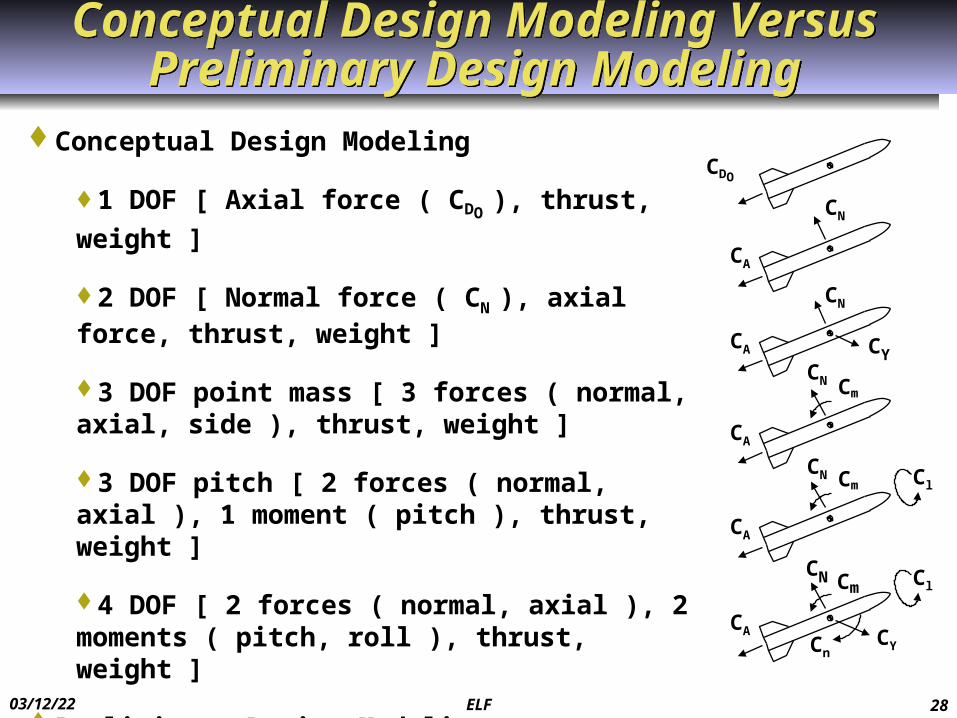
Conceptual Design Modeling
1 DOF [ Axial force ( CDO ), thrust, weight ]
2 DOF [ Normal force ( CN ), axial force, thrust, weight ]
3 DOF point mass [ 3 forces ( normal, axial, side ), thrust, weight ]
3 DOF pitch [ 2 forces ( normal, axial ), 1 moment ( pitch ), thrust, weight ]
4 DOF [ 2 forces ( normal, axial ), 2 moments ( pitch, roll ), thrust, weight ]
Preliminary Design Modeling
6 DOF [ 3 forces ( normal, axial, side ), 3 moments ( pitch, roll, yaw ), thrust, weight ]
CDO
CN
CN
CN Cm
CA
CA
CA
CA
CA
Cl
ClCN Cm
CN Cm
CnCY
CY

04/07/23 ELF 29
3 DOF Simplified Equations of Motion Show Drivers for Configuration Sizing
3 DOF Simplified Equations of Motion Show Drivers for Configuration Sizing
Configuration Sizing Implication
y ..
q SRef d Cm + q SRef d Cm
High Control Effectiveness Cm >
Cm, Iy small ( W small ), q large
( W / gc ) V . q SRef CN + q SRef CN
- W cos Large / Fast Heading Change CN
large, W small, q large
( W / gc ) V. T - CA SRef q - CN
2 SRef q - W sin High Speed / Long Range Total
Impulse large, CA small, q small
+ Normal Force
<< 1 rad
W
+ MomentV
+ Thrust
+ Axial Force
Note: Based on aerodynamic control

04/07/23 ELF 30
1.00E+05
1.00E+06
1.00E+07
1.00E+08
0 0.1 0.2 0.3 0.4 0.5 0.6 0.7 0.8
WP / WBC, Propellant or Fuel Weight / Weight at Begin of Cruise
R, C
ruis
e R
ange
, ft
(VISP)(L/D) = 2,000,000 ft (VISP)(L/D) = 10,000,000 ft(VISP)(L/D) = 25,000,000 ft
For Long Range Cruise, Maximize V Isp, L / D, And Fuel or Propellant Weight Fraction
For Long Range Cruise, Maximize V Isp, L / D, And Fuel or Propellant Weight Fraction
Example: Ramjet Baseline at Mach 3 / 60 Kft altR = 2901 ( 1040 ) ( 3.15 ) ln [ 1739 / ( 1739 - 476 )]= ( 9,503,676 ) ln [ 1 / ( 1 - 0.2737 )] = 3,039,469 ft = 500 nm
R = ( V Isp ) ( L / D ) ln [ WBC / ( WBC - WP )] , Breguet Range Equation
Note: R = cruise range, V = cruise velocity, ISP = specific impulse, L = lift, D = drag, WBC = weight at begin of cruise, WP = weight of propellant or fuel
Typical RocketTypical Ramjet with Axisymmetric AirframeRamjet with High L / D Airframe

04/07/23 ELF 31
Efficient Steady Flight Is Enhanced by High L / D and Light Weight
Efficient Steady Flight Is Enhanced by High L / D and Light Weight
Steady Level Flight Steady Climb Steady Descent
T = DL = W
L
D T
W
C
SIN D = ( D – T ) / W = VD / V
VD = ( D – T ) V/ WRD = h / tan D = h ( L / D )
T – D
L
DT
W
VC VC
D – TL
D
TW
DVD
D
• Small Angle of Attack• Equilibrium Flight• VC = Velocity of Climb• VD = Velocity of DescentC = Flight Path Angle During ClimbD = Flight Path Angle During Descent• V = Total Velocityh = Incremental Altitude• RC = Horizontal Range in Steady Climb• RD = Horizontal Range in Steady Dive ( Glide )
Note:
Reference: Chin, S.S., “Missile Configuration Design,” McGraw Hill Book Company, New York, 1961
VT = W / ( L / D ) SIN c = ( T – D ) / W = Vc / V
Vc = ( T – D ) V / W
RC = h / tan C = h ( L / D )

04/07/23 ELF 32
Small Turn Radius Requires High Angle of Attack and Low Altitude Flight
Small Turn Radius Requires High Angle of Attack and Low Altitude Flight
RT,
Exam
ple
Inst
anta
neou
s Tu
rn R
adiu
s, F
eet
= Increment in Angle of Attack Required to Turn, Degrees
h = 100 K ft ( M(L/D)Max = 7.9 )
h = 80 K ft ( M(L/D)Max = 5.0 )
h = 60 K ft ( M(L/D)Max = 3.1 )
h = 40 K ft ( M(L/D)Max = 1.9 )
10,000,000
1,000,000
100,000
10,000
1,0000 5 10 15 20
• • • •
•
•
•
•
•
•
•
•
Note for Example:W = Weight = 2,000 lba / b = 1 ( circular cross section ), No wingsCN = sin 2 cos ( / 2 ) + 2 ( l / d ) sin2 l / d = Length / Diameter = 10SRef = 2 ft2
CDO = 0.2
( L / D )Max = 2.7, q( L / D )Max = 1,000 psf
( L / D )Max = 15 degrees
T( L / D )Max= 740 lb
Example:
= 10 deg
CN = 0.99
h = 40K ft ( ρ = 0.00039 slugs / ft3 )
RT = 2 ( 2,000 ) / [( 32.2 ) ( 0.99 ) ( 2 ) ( 0.00039 )] = 161,000 ft
RT = V / . 2 W / ( gc CN SRef )

04/07/23 ELF 33
Turn Rate Performance Requires High Control Effectiveness
Turn Rate Performance Requires High Control Effectiveness
. = gc n / V = [ q SRef CN + q SRef CN - W cos ( ) ] / [( W / gc ) V ] Assume Rocket Baseline @ Mach 0.8 Launch, 20K ft Altitude
(Cm)xcg=84.6 = (Cm
)xcg=75.7 + CN ( 84.6 – 75.7 ) / d = - 0.40 + 0.68 ( 8.9 ) / 8 = 0.36 per deg
(Cm)xcg=84.6 = (Cm
)xcg=75.7 + CN ( 84.6 – 75.7 ) / d = 0.60 + 0.27( 8.9 ) / 8 = 0.90 per deg
/ = - Cm / Cm= - 0.90 / 0.36 = - 2.5
’ = + < 22 degrees, max = 30 deg = 30 deg, = - 12 deg . = [ 436 ( 0.349 )( 0.68 )( 30 ) + 436 ( 0.349 )( 0.27 )( - 12 ) – 500 ( 1 )] / [( 500 / 32.2 )( 830 )] = 0.164 rad / sec or 9.4 deg / sec
Assume Rocket Baseline @ Mach 2 Coast, 20K ft Altitude / = 0.75 ’ = + = 22 degrees = 12.6 deg, = 9.4 deg . = [ 2725 ( 0.349 )( 0.60 )( 9.4 ) +2725 ( 0.349 )( 0.19 )( 12.6 ) – 367 ( 1 )] / ( 367 / 32.2 )( 2074 ) = 0.31 rad / sec or 18 deg / sec Note: High q, statically stable, forward wing control, lighter weight higher climb capability Note: Forward wing deflection to trim increases normal force

04/07/23 ELF 34
For Long Range Coast, Maximize Initial VelocityFor Long Range Coast, Maximize Initial Velocity
0
0.2
0.4
0.6
0.8
1
1.2
0 0.5 1 1.5 2
Example for Rocket Baseline:
•WBO = 367 lb, SRef = 0.349 ft2, VBO = 2,151 ft / sec, = 0 deg, CD0 = 0.9, h = 20,000 ft ( ρ = 0.00127 slugs / ft3 ), t = 10 sec
•t / [ 2 WBO / ( gc ρ SRef CD0 VBO )] = 10 / { 2 ( 367 ) / [ 32.2 ( 0.00127 ) ( 0.349 ) ( 0.9 ) ( 2151 ) ]} = 10 / 26.6 = 0.376
•V / VBO = 0.727, V = 0.727 x 2151 = 1564 ft / sec, R / [ 2 WBO / ( gc ρ SRef CD 0 )] = 0.319, R = 18,300 ft or 3.0 nm
t / [ 2 W / ( g ρS CD0 VBC )], Non-dimensional Coast Time
V / VBO = 1 / { 1 + t / { 2 WBO / [ gc ρAVG SRef ( CD0 )AVG VBO ]}}
R / { 2 WBO / [ gc ρAVG SRef (CD0 )AVG ]} = ln {1 + t / { 2
WBO / [ gc ρAVG SRef ( CD0 )AVG VBO ]}}
Note: Based on 1DoF
dV / dt = - gc CD0 SRef q / W
Assumptions:
= constant
0 deg
• D > W sin
V = velocity during coast
VBO = velocity @ burnout ( begin coast )
R = coast range
Vx = V cos , Vy = V sin
Rx = R cos , Ry = R sin

04/07/23 ELF 35
For Long Range Ballistic Flight, Maximize Initial Velocity
For Long Range Ballistic Flight, Maximize Initial Velocity
0
0.2
0.4
0.6
0.8
1
1.2
0 0.5 1 1.5 2
t / [ 2 W / ( g ρS CD0 Vi )], Non-dimensional Time
Vx / ( Vi cos i ) = 1 / { 1 + t / { 2 WBO / [ gc ρAVG SRef ( CD0 )AVG Vi ]}}
( Vy + gc t ) / ( Vi sin i ) = 1 / { 1 + t / { 2 WBO / [ gc ρAVG SRef ( CD0 )AVG Vi ]}
Assumptions: T = 0, = 0 deg, D > W sin , flat earth
Nomenclature: V = velocity during ballistic flight, Vi = initial velocity, Rx = horizontal range, h = altitude, hi = initial altitude, Vx = horizontal velocity, Vy = vertical velocity
Example for Rocket Baseline:
•WBO = 367 lb, SRef = 0.349 ft2, Vi = VBO = 2,151 fps, i = 0 deg, ( CD0 )AVG = 0.9, hi = 20,000 ft, ρAVG = 0.001755 slugs / ft3, t = 35 sec
•t / [ 2 WBO / ( gc ρ SRef CD0 Vi )] = 35 / { 2 ( 367 ) / [ 32.2 ( 0.001755 ) ( 0.349 ) ( 0.9 ) ( 2151 ) ]} = 35 / 19.22 = 1.821
•Vx / ( Vi cos i ) = 0.354 Vx = 762 ft / sec, ( Vy + 32.2 t ) / ( Vi sin i ) = 0.354 Vy = - 1127 ft / sec, Rx / [ 2 Wi cos i / ( gc ρ SRef CD 0
)] = 1.037 Rx = 42,900 ft or 7.06 nm, ( h – hi + 16.1 t2 ) / [ 2 WBO cos i / ( gc ρ SRef CD 0 )] = 1.037 h = 0 ft
Rx / { 2 WBO cos i / [ gc ρAVG SRef (CD0 )AVG ]} = ln { 1 + t / { 2
WBO / [ gc ( ρ )AVG SRef ( CD0 )AVG Vi ]}}
( h – hi + gc t2 / 2 ) / { 2 WBO sin i / [ gc ρAVG SRef (CD0 )AVG ]} =
ln { 1 + t / { 2 WBO / [ gc ρAVG SRef ( CD0 )AVG Vi ]}

04/07/23 ELF 36
High Propellant Weight and High Thrust Provide High Burnout Velocity
High Propellant Weight and High Thrust Provide High Burnout Velocity
0
0.1
0.2
0.3
0.4
0.5
0.6
0.7
0 0.1 0.2 0.3 0.4 0.5
Wp / Wi, Propellant Fraction
Del
ta V
/ ( g
ISP
), N
ondi
men
sion
al
Incr
emen
tal V
eloc
ity
DAVG / T = 0 DAVG / T = 0.5 DAVG / T = 1.0
V / ( gc ISP ) = - ( 1 - DAVG / T ) ln ( 1 - Wp / Wi )Example for Rocket Baseline:
Wi = WL = 500 lb
For boost, WP = 84.8 lb
WP / WL = 0.1696
ISP = 250 sec
TB = 5750 lb
Mi = ML = 0.8, hi = hL = 20,000 ft
DAVG = 635 lb
DAVG / T = 0.110
V / [( 32.2 ) ( 250 )] = - ( 1 -
0.110 ) ln ( 1 - 0.1696 ) = 0.1654
V = ( 0.1654 ) ( 32.2 ) ( 250 )
= 1331 ft / sec
Note: 1 DOF Equation of Motion with 0 deg, = constant, and T > W sin , Wi = initial weight, WP = propellant weight, ISP = specific impulse, T = thrust, Mi = initial Mach number, hi = initial altitude, DAVG = average drag, V = incremental velocity, gc = gravitation constant, Vx = V cos , Vy = V sin , Rx = R cos , Ry = R sin
Note: R = ( Vi + V / 2 ) tB, where R = boost range, Vi = initial velocity, tB = boost time

04/07/23 ELF 37
High Missile Velocity and Lead Are Required to Intercept High Speed Crossing Targets
High Missile Velocity and Lead Are Required to Intercept High Speed Crossing Targets
VM / VT
4
3
2
00 10 20 30 40 50
L, Lead Angle, Degrees
1
A = 90°
A = 45°
Note: Proportional GuidanceVM = Missile VelocityVT = Target VelocityA = Target AspectL = Missile Lead Angle
Seeker Gimbal
VM VTL A
VM sin L = VT sin A, Proportional Guidance Trajectory
Example:
L = 30 degrees
A = 45 degreesVM / VT = sin ( 45 ) / sin ( 30 ) = 1.42

04/07/23 ELF 38
Example of Spreadsheet Based Conceptual Sizing Computer Code - TMD Spreadsheet
Example of Spreadsheet Based Conceptual Sizing Computer Code - TMD Spreadsheet
Define Mission Requirements [ Flight Performance ( RMax, RMin, VAVG ) , MOM, Constraints ]
Establish Baseline ( Rocket , Ramjet )
Aerodynamics Input ( d, l, lN, A, c, t, xcg ) Aerodynamics Output [ CD0
, CN, XAC, Cm , L / D, ST ]
Propulsion Input ( pc, , c*, Ab, At, A3, Hf, , T4, Inlet Type )
Propulsion Output [ Isp, Tcruise, pt2 / pt0
, w., Tboost, Tsustain, VBoost ]
Weight Input ( WL, WP, max )Weight Output [ Q, dTskin / dt, Tskin, skin , tskin, buckling, MB, ( Ft )Motor, W, xcg, Iy ]
Trajectory Input ( hi, Vi, Type ( cruise, boost, coast, ballistic, turn, glide )Trajectory Output ( R, V, and versus time )
MeetPerformance?
Measures of Merit and Constraints
No [ pBlast, PK, nHits, Vfragments, PKE, KEWarhead, Total, HE, MAN, Rdetect,
CWeight, Cunit x ]
No [ RMax, RMin, VAVG ]
Yes
Yes
Alt Mission
Alt Baseline
Resize / Alt Config / Subsystems / Tech

04/07/23 ELF 39
OutlineOutline
Examples of Parameters and Technologies That Drive Missile Flight Performance
Missile Flight Performance Prediction Examples of Maximizing Missile Flight Performance
( Workshop ) Summary

04/07/23 ELF 40
Rocket Baseline Missile ConfigurationRocket Baseline Missile Configuration
STA 60.819.4
3.418.5
STA 125.4
LEMAC at STA 67.0BL 10.2
= 45
40.2STA 0 19.2 46.1 62.6 84.5 138.6
Note: Dimensions in inches
Source: Bithell, R.A. and Stoner, R.C., “Rapid Approach for Missile Synthesis, Vol. 1, Rocket Synthesis Handbook,” AFWAL-TR-81-3022, Vol. 1, March 1982.
Nose Forebody PayloadBay
Midbody Aftbody Tailcone
Rocket Motor = 57
12.0
LEMAC at
STA 131.6BL 8.0
16.18.0 d
cgBO cgLaunch
143.9

04/07/23 ELF 41
Rocket Baseline Missile Propellant Weight Is 27% of the Launch Weight
Rocket Baseline Missile Propellant Weight Is 27% of the Launch Weight
1 Nose ( Radome ) 4.1 12.03 Forebody structure 12.4 30.5
Guidance 46.6 32.62 Payload Bay Structure 7.6 54.3
Warhead 77.7 54.34 Midbody Structure 10.2 73.5
Control Actuation System 61.0 75.55 Aftbody Structure 0.0 –
Rocket Motor Case 47.3 107.5Insulation 23.0 117.2
6 Tailcone Structure 6.5 141.2Nozzle 5.8 141.2
Fixed Surfaces 26.2 137.8Movable Surfaces 38.6 75.5
Burnout Total 367.0 76.2Propellant 133.0 107.8
Launch Total 500.0 84.6
Component Weight, lbs. C.G. STA, In.

04/07/23 ELF 42
Rocket Baseline Missile Has Boost-Sustain Thrust - Time History
Rocket Baseline Missile Has Boost-Sustain Thrust - Time History
Time – Seconds0 4 8 12 16
0
2
4
6
8
Thrust – 1,000 lbs
Note: Sea Level, 60°F

04/07/23 ELF 43
Rocket Baseline Missile Has Higher Maneuverability at High Angle of Attack
Rocket Baseline Missile Has Higher Maneuverability at High Angle of Attack
4
0
0 4 8 12 16, Angle of Attack – Degrees
12
8
20
CN, N
orm
al F
orce
Coe
ffici
ent
20
16
24
1.2
0.6
M = 1.2
1.52.0 2.35
2.87 3.954.60
SRef = 0.349 ft2, lRef = d = 0.667 ft, C.G. at STA 75.7, = 0 deg

04/07/23 ELF 44
Rocket Baseline Missile Control Effectiveness and Drag Are Driven by Mach Number
Rocket Baseline Missile Control Effectiveness and Drag Are Driven by Mach Number
0.4
00 1 2 3 4
M, Mach Number
1.2
0.8
5
CA
at
= 0
°
0.1
0
Power Off
Power On
0.2
0.3
CN
~ Pe
r Deg
ree

04/07/23 ELF 45
-5
0
5
10
15
0 5 10 15 20 25
t, Time, sec
nx, A
xial
Acc
eler
atio
n, g
Rocket Baseline Has High Boost Acceleration Rocket Baseline Has High Boost Acceleration
Note:tf = 24.4 sec
ML = 0.8
hL = 20,000 ft
TB = 5750 lb
tB = 3.26 sec
TS = 1018 lb
tS = 10.86 secD = 99 lb at Mach 0.8D = 1020 lb at Mach 2.1
WL = 500 lb
WP = 133 LB
nX = ( T - D ) / W
Boost
Sustain
Coast

04/07/23 ELF 46
0
1000
2000
3000
0 5 10 15 20 25
t, Time, sec
V, V
elocit
y, ft
/ sec
Rocket Baseline Missile Has Nearly Constant Velocity During Sustain
Rocket Baseline Missile Has Nearly Constant Velocity During Sustain
Boost
Sustain
Coast
V / ( gc ISP ) = - ( 1 - DAVG / T ) ln ( 1 - Wp / Wi ), During Boost
V / VBO = 1 / { 1 + t / { 2 WBO / [ gc ρAVG SRef ( CD0 )AVG VBO ]}}, During Coast
Note:
ML = 0.8
hL = 20K feet

04/07/23 ELF 47
Rocket Baseline Missile Maximum Range Is About Eight Nautical Miles
Rocket Baseline Missile Maximum Range Is About Eight Nautical Miles
0
2
4
6
8
10
0 5 10 15 20 25
t, Time, sec
R, F
light
Ran
ge, n
m
Boost
Sustain
Coast
R = Rboost + Rsustain + Rcoast
Note:
ML = 0.8
hL = 20K feet

04/07/23 ELF 48
Rocket Baseline Missile Has About 30 G Maneuverability
Rocket Baseline Missile Has About 30 G Maneuverability
( nZ ) = ( nZ )Body + ( nZ )Wing + ( nZ )Taill
Rocket Baseline @ •Mach 2•20,000 ft altitude•367 lb weight ( burnout )
ComputeWing = ’Max = ( + )Max = 22 deg for rocket baseline
= 0.75, Body = Tail = 9.4 deg
( nZ )Body = q SRef ( CN )Body / W = 2725 ( 0.35 ) ( 1.1 ) / 367 = 2.9 g ( from body )
( nZ )Wing = q SWing [( CN )Wing (SRef / SWing )] / W = 2725 ( 2.55 ) ( 1.08 ) / 367 = 20.4 g ( from wing )
( nZ )Tail = q STail [( CN )Tail ( SRef / STail )] / W = 2725 ( 1.54 ) ( 0.50 ) / 367 = 5.7 g ( from tail )
nZ = 2.9 + 20.4 + 5.7 = 29 g

04/07/23 ELF 49
Example of Boost Climb - Ballistic TrajectoryExample of Boost Climb - Ballistic Trajectory
Assume Rocket Baseline @ i = 45 deg, hi = hf = 0 ft
Velocity, Horizontal Range, and Altitude During Initial Boost @ = 45 degV = - gc ISP ( 1 - DAVG / T ) ln ( 1 - Wp / Wi ) = -32.2 ( 250 ) ( 1 – 419 / 5750 ) ln ( 1 – 84.8 / 500 ) = 1,387 ft / sec
R = ( Vi + V / 2 ) tB = ( 0 + 1387 / 2 ) 3.26 = 2,260 ft
Rx = R cos i = 2260 ( 0.707 ) = 1,598 ft
Ry = R sin i = 2260 ( 0.707 ) = 1,598 ft
h = hi + Ry = 0 + 1598 = 1,598 ft Velocity, Horizontal Range, and Altitude During Sustain @ = 45 deg
V = - gc ISP ( 1 - DAVG / T ) ln ( 1 - Wp / Wi ) = -32.2 ( 230.4 ) ( 1 – 650 / 1018 ) ln ( 1 – 48.2 / 415.2 ) = 585 ft / sec
VBO = 1387 + 585 = 1,972 ft / sec
R = ( Vi + V / 2 ) tB = ( 1387 + 585 / 2 ) 10.86 = 18,239 ft
Rx = R cos i = 18239 ( 0.707 ) = 12,895 ft
Ry = R sin i = 18239 ( 0.707 ) = 12,895 ft
h = hi + Ry = 1598 + 12895 = 14,493 ft
04/07/23 ELF 50
Example of Boost Climb - Ballistic Trajectory ( cont )
Example of Boost Climb - Ballistic Trajectory ( cont )
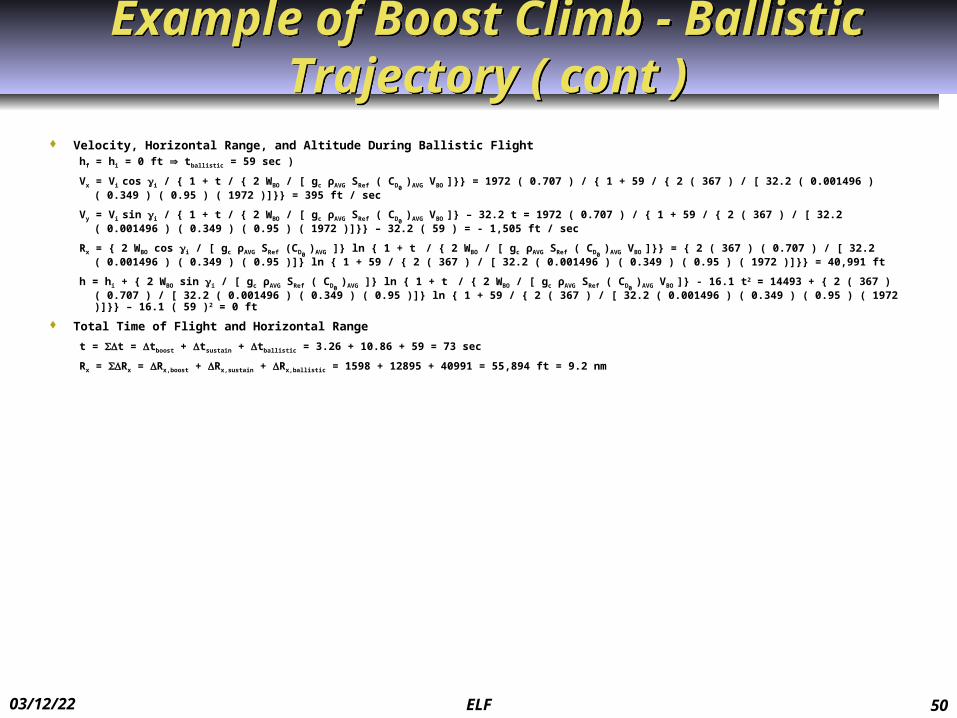
Velocity, Horizontal Range, and Altitude During Ballistic Flighthf = hi = 0 ft tballistic = 59 sec )
Vx = Vi cos i / { 1 + t / { 2 WBO / [ gc ρAVG SRef ( CD0 )AVG VBO ]}} = 1972 ( 0.707 ) / { 1 + 59 / { 2 ( 367 ) / [ 32.2 ( 0.001496 ) ( 0.349 ) ( 0.95 ) ( 1972 )]}} = 395 ft / sec
Vy = Vi sin i / { 1 + t / { 2 WBO / [ gc ρAVG SRef ( CD0 )AVG VBO ]} – 32.2 t = 1972 ( 0.707 ) / { 1 + 59 / { 2 ( 367 ) / [ 32.2 ( 0.001496 ) ( 0.349 ) ( 0.95 ) ( 1972 )]}} – 32.2 ( 59 ) = - 1,505 ft
/ sec
Rx = { 2 WBO cos i / [ gc ρAVG SRef (CD0 )AVG ]} ln { 1 + t / { 2 WBO / [ gc ρAVG SRef ( CD0
)AVG VBO ]}} = { 2 ( 367 ) ( 0.707 ) / [ 32.2 ( 0.001496 ) ( 0.349 ) ( 0.95 )]} ln { 1 + 59 / { 2 ( 367 ) / [ 32.2 ( 0.001496 ) ( 0.349 ) ( 0.95 ) ( 1972 )]}} = 40,991 ft
h = hi + { 2 WBO sin i / [ gc ρAVG SRef ( CD0 )AVG ]} ln { 1 + t / { 2 WBO / [ gc ρAVG SRef ( CD0
)AVG VBO ]} - 16.1 t2 = 14493 + { 2 ( 367 ) ( 0.707 ) / [ 32.2 ( 0.001496 ) ( 0.349 ) ( 0.95 )]} ln { 1 + 59 / { 2 ( 367 ) / [ 32.2 ( 0.001496 ) ( 0.349 ) ( 0.95 ) ( 1972 )]}} – 16.1 ( 59 )2 = 0 ft
Total Time of Flight and Horizontal Range
t = t = tboost + tsustain + tballistic = 3.26 + 10.86 + 59 = 73 sec
Rx = Rx = Rx,boost + Rx,sustain + Rx,ballistic = 1598 + 12895 + 40991 = 55,894 ft = 9.2 nm
04/07/23 ELF 51
Boost Climb – Ballistic – Glide Trajectory Provides Extended Range
Boost Climb – Ballistic – Glide Trajectory Provides Extended Range
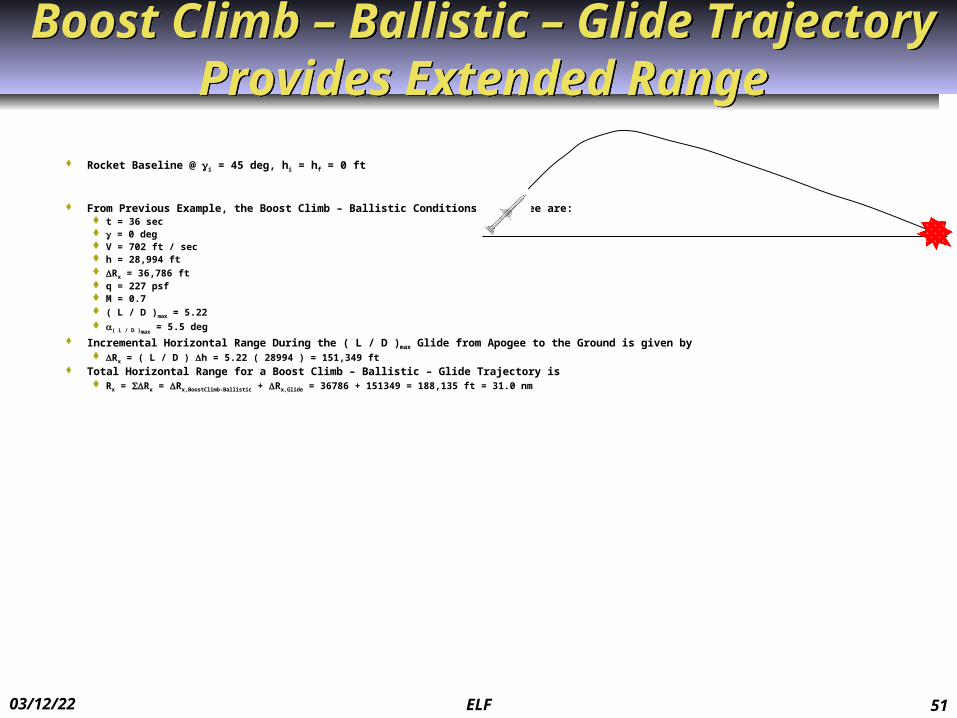
Rocket Baseline @ i = 45 deg, hi = hf = 0 ft
From Previous Example, the Boost Climb – Ballistic Conditions at Apogee are: t = 36 sec = 0 deg V = 702 ft / sec h = 28,994 ft Rx = 36,786 ft q = 227 psf M = 0.7 ( L / D )max = 5.22 ( L / D )max
= 5.5 deg
Incremental Horizontal Range During the ( L / D )max Glide from Apogee to the Ground is given by Rx = ( L / D ) h = 5.22 ( 28994 ) = 151,349 ft
Total Horizontal Range for a Boost Climb – Ballistic – Glide Trajectory is Rx = Rx = Rx,BoostClimb-Ballistic + Rx,Glide = 36786 + 151349 = 188,135 ft = 31.0 nm

04/07/23 ELF 52
Glide at ( L / D )max Provides Extended RangeGlide at ( L / D )max Provides Extended Range
0
10
20
30
0 10 20 30 40
R, Range, nm
h, A
ltitu
de, K
ilo F
eet
Sust
ain
Bal
listic
Note: Rocket Baseline
End of boost, t = 3.26 sec, = 45 deg, V = 1387 ft / sec
End of sustain, t = 14.12 sec, = 45 deg, V = 1972 ft / sec
Apogee, t = 36 sec, = 0 deg, V = 702 ft / sec
Ballistic impact, t = 73 sec, = - 65 deg, V = 1556 ft / sec
Glide impact, t = 286 sec, = - 10.8 deg, V = 500 ft / sec
Ballistic
Glide at ( L / D )max
04/07/23 ELF 53
Soda Straw Rocket Design, Build, and FlySoda Straw Rocket Design, Build, and Fly
Objective – Hands-on Learning of Rocket Physics Based on Design Build Fly
Furnished Property 1 Launch System 1 Target 1 Weight Scale
Furnished Material 1 Soda Straw: ¼ in Inside Diameter by 11 in Length 1 Strip Tabbing: ½ in by 6 in 1 Tape Dispenser 1 Wood Dowel: ¼ in Diameter by 1 in Length

04/07/23 ELF 54
Soda Straw Rocket ( cont )Soda Straw Rocket ( cont ) Design – Soda Straw Rocket
Compatible with Furnished Property Launch System Launch tube outside diameter: ¼ in Launch tube length: 6 in Launch static gauge pressure: up to 30 psi
Design Body and Tails for Maximum flight range Accurate and stable flight
Calculate Aerodynamic Drag Coefficient Skin friction drag Base drag
Calculate Thrust and Thrust Duration Measure Weight
0.1 gram accuracy Predict Flight Range and Altitude for Proscribed
Launch pressure Elevation angle

04/07/23 ELF 55
Soda Straw Rocket ( cont )Soda Straw Rocket ( cont )
Build - Soda Straw Rocket Using Either Furnished Material Or Can Use Own Material
Fly - Soda Straw Rocket Proscribed Target Location, Launch Location, Launch Pressure, and Launch Angle Compare Flight Test Results for Alternative Concepts
Highest vertical location of impact Smallest horizontal dispersal from impact aim point
Discuss Reasons for Performance of Alternative Concepts

04/07/23 ELF 56
Example Baseline Configuration Geometry, Weight, and Balance
Example Baseline Configuration Geometry, Weight, and Balance
Example Baseline Configuration Diameter = d = ¼ in = 0.0208 ft Outside Length = l = 5 in = 0.417 ft Inside Cavity Length Available for Launch Tube = lc = 4 in = 0.333 ft Hemispherical Nose Reference Area = SRef = ( / 4 ) d2 = 0.0491 in2 = 0.000341 ft2
4 Tail Panels ( Cruciform Tails, nT = 2 ) Each tail panel ½ in by 1 in Mean aerodynamic chord = cmac = 1 in = 0.0833 ft Exposed area of 2 tail panels = ST = 1 in2 = 0.00694 ft2
Exposed aspect ratio of 2 tail panels = A = b2 / ST = ( 1 )2 / ( 1 ) = 1.0
Example Baseline Weight and Balance W = 1.9 gram = 0.0042 lb Xcg / l = 0.55
llccll

04/07/23 ELF 57
Example Baseline Boost PerformanceExample Baseline Boost Performance
During Boost, Thrust ( T ) Provided by Pressurized Launch Tube T = ( p – p0 ) A = pgauge ( 1 – e – t / ) A A = SRef = 0.0491 in2, = Rise Time to Open Valve Assume pgauge = 20 psi, = 0.2 sec T = 20 ( 1 - e – t / 0.2 ) ( 0.0491 ) = 0.982 ( 1 - e – 5.00 t ) Actual Thrust Lower ( Pressure Loss, Boundary Layer, Launch Tube Friction )
Acceleration ( a ), Velocity ( V ), and Distance ( s ) During Boost a 32.2 T / W = 32.2 ( 0.982 ) ( 1 - e – 5.00 t ) / 0.0042 = 7528.667 ( 1 - e – 5.00 t ) V = 7528.667 t + 1505.733 e – 5.00 t – 1505.733 s = 3764.333 t2 – 301.147 e – 5.00 t – 1505.733 t + 301.147
End of Boost Conditions s = lc = 0.333 ft t = 0.0382 sec V = 25.8 ft / sec q = ½ V2 = ½ ( 0.002378 ) ( 25.8 )2 = 0.791 psf M = V / c = 25.8 / 1116 = 0.0231

04/07/23 ELF 58
Example Baseline Drag CoefficientExample Baseline Drag Coefficient
Total Drag Coefficient CD0 = (CD0
)Body + (CD0 )Tail
During Coast, CD0 = ( CD0
)Body,Friction + (CD0 )Base,Coast + ( CD0
)Tail,Friction = 0.053 ( l / d ) [ M / ( q l )]0.2 +
0.12 + nT { 0.0133 [ M / ( q cmac )]0.2 } ( 2 ST / SRef ) CD0
= 0.053 ( 20 ){ 0.0231 / [( 0.791 ) ( 0. 417 )]}0.2 + 0.12 + 2 { 0.0133 { 0.0231 / [( 0.791 ) ( 0.0833 )]}0.2}[ 2 ( 0.00694 ) / 0.000341 )] = 0.62 + 0.12 + 0.88 = 1.62
Above Drag Coefficient Not Exact Based on Assumption of Turbulent Boundary Layer Soda Straw Rocket Is Small Size and Low Velocity Laminar Boundary Layer

04/07/23 ELF 59
Example Ballistic Flight PerformanceExample Ballistic Flight Performance
Horizontal Range Equation
Rx = { 2 W cos i / [ gc ρ SRef CD0 ]} ln { 1 + t / { 2 W / [ gc ρ SRef CD0
Vi ]} = { 2 ( 0.0042 ) cos i / [ 32.2 ( 0.002378 ) ( 0.000341 ) ( 1.62 )]} ln
{ 1 + t / { 2 ( 0.0042 ) / [ 32.2 ( 0.002378 ) ( 0.000341 ) ( 1.62 ) ( 25.8 )]} = 199 cos i ln ( 1 + 0.130 t )
Height Equation
h = { 2 W sin i / [ gc ρ SRef CD0 ]} ln { 1 + t / { 2 W / [ gc ρ SRef CD0
Vi ]} + hi - gc t2 / 2 = { 2 ( 0.0042 ) sin i / [ 32.2 ( 0.002378 ) ( 0.000341 )
( 1.62 )} ln { 1 + t / { 2 ( 0.0042 ) / [ 32.2 ( 0.002378 ) ( 0.000341 ) ( 1.62 ) ( 25.8 )]} + hi – 32.2 t2 / 2 = 199 sin i ln ( 1 + 0.130 t ) + hi – 32.2 t2 / 2
Assume i = 45 deg, t = timpact = 0.9 sec Rx = 199 ( 0.707 ) ln [ 1 + 0.130 ( 0.9 )] = 15.5 ft h = 199 ( 0.707 ) ln [ 1 + 0.130 ( 0.9 )] + hi – 32.2 ( 0.9 )2 / 2 = hi +2.5

04/07/23 ELF 60
Soda Straw Rocket Range Driven by Length, Gauge Pressure, Valve Open Time , and Weight
Soda Straw Rocket Range Driven by Length, Gauge Pressure, Valve Open Time , and Weight
-0.4
-0.2
0
0.2
0.4
0.6
0.8
l pgauge tau W CD0
Nondimensional Range
Sensitivity to Parameter
Note: Soda Straw Rocket Baseline:
W = Weight = 0.0042 lb
l = length = 5 in
= Time constant to open valve = 0.2 sec
pgauge = gauge pressure = 20 psi
V = Launch Velocity = 25.8 fps
CD0 = Zero-lift drag coefficient =
1.62
i = Initial flight path angle = 45 deg
timpact = Time from launch to impact = 0.9 sec
Rx = Horizontal range = 15.5 ft
Example: 10% increase in rocket length 7.1% increase in range

04/07/23 ELF 61
OutlineOutline
Examples of Parameters and Technologies That Drive Missile Flight Performance
Missile Flight Performance Prediction Examples of Maximizing Missile Flight Performance
( Workshop ) Summary

04/07/23 ELF 62
SummarySummary Flight Performance Analysis Activity in Missile Design and Analysis
Compute Range, Velocity, Time-to-Target, Off Boresight Compare with Requirements and Data
Maximizing Flight Performance Strongly Impacted by Aerodynamics Propulsion Weight Flight Trajectory
Lecture Topics Aerodynamics Parameters, Prediction and Technologies
Drag Coefficient Normal Force Coefficient
Propulsion Parameters, Prediction, and Technologies Thrust Specific Impulse

04/07/23 ELF 63
Summary ( cont )Summary ( cont ) Lecture Topics ( continued )
Flight Performance Parameters and Technologies Cruise Range High Density Fuel and Packaging Flight Trajectory Shaping Range Sensitivity to Driving Parameters Missile Follow-on Programs Examples of State-of-the-Art Advancements Summary of New Technologies
Flight Performance Envelope Videos of Flight Performance Modeling of Degrees of Freedom Equations of Motion and Flight Performance Drivers Steady State Flight Relationships Flight Performance Prediction
Steady Climb and Steady Dive Range Prediction Cruise Prediction

04/07/23 ELF 64
Summary ( cont )Summary ( cont )
Lecture Topics ( continued ) Flight Performance Prediction ( continued )
Boost Prediction Coast Prediction Ballistic Flight Prediction Turn Prediction
Target Lead for Proportional Homing Guidance Tactical Missile Design Spreadsheet
Workshop Examples Rocket Boost-Coast Range Rocket Maneuverability Rocket Ballistic Range Rocket Trajectory Optimization Soda Straw Rocket Design, Build, and Fly

04/07/23 ELF 65
Configuration Sizing Criteria for Maximizing Flight Performance
Configuration Sizing Criteria for Maximizing Flight Performance
Body Fineness Ratio 5 < l / d < 25Nose Fineness Ratio lN / d 2 if M > 1Efficient Cruise Dynamic Pressure q < 700 psfMissile Homing Velocity VM / VT > 1.5Subsystems Packaging Maximize available volume
for fuel / propellantTrim Control Power / > 1Missile Maneuverability nM / nT > 3

04/07/23 ELF 66
Bibliography 0f Reports and Web SitesBibliography 0f Reports and Web Sites “Missile.index,” http://www.index.ne.jp/missile_e/ AIAA Aerospace Design Engineers Guide, American Institute of Aeronautics and Astronautics, 1993. Bonney, E.A., et al, Aerodynamics, Propulsion, Structures, and Design Practice, “Principles of Guided Missile
Design”, D. Van Nostrand Company, Inc., Princeton, New Jersey, 1956 Chin, S.S., Missile Configuration Design, McGraw-Hill Book Company, New York, 1961 Mason, L.A., Devan, L., and Moore, F.G., “Aerodynamic Design Manual for Tactical Weapons,” NSWCTR 81-156, 1981 Pitts, W.C., Nielsen, J.N., and Kaattari, G.E., “Lift and Center of Pressure of Wing-Body-Tail Combinations at
Subsonic, Transonic, and Supersonic Speeds,” NACA Report 1307, 1957. Jorgensen, L.H., “Prediction of Static Aerodynamic Characteristics for Space-Shuttle-Like, and Other Bodies at
Angles of Attack From 0 to 180,” NASA TND 6996, January 1973 Hoak, D.E., et al., “USAF Stability and Control Datcom,” AFWAL TR-83-3048, Global Engineering Documents, Irvine,
CA, 1978 “Nielsen Engineering & Research (NEAR) Aerodynamic Software Products,”
http://www.nearinc.com/near/software.htm Jerger, J.J., Systems Preliminary Design Principles of Guided Missile Design, “Principles of Guided Missile Design”,
D. Van Nostrand Company, Inc., Princeton, New Jersey, 1960 Schneider, S.H., Encyclopedia of Climate and Weather, Oxford University Press, 1996 Klein, L.A., Millimeter-Wave and Infrared Multisensor Design and Signal Processing, Artech House, Boston, 1997 US Army Ordnance Pamphlet ORDP-20-290-Warheads, 1980 Nicholas, T. and Rossi, R., “US Missile Data Book, 1996,” Data Search Associates, 1996 Bithell, R.A., and Stoner, R.C., “Rapid Approach for Missile Synthesis,” AFWAL TR 81-3022, Vol. I, March 1982 Fleeman, E.L. and Donatelli, G.A., “Conceptual Design Procedure Applied to a Typical Air-Launched Missile,” AIAA
81-1688, August 1981 Hindes, J.W., “Advanced Design of Aerodynamic Missiles ( ADAM ),” October 1993

04/07/23 ELF 67
Bibliography of Reports and Web Sites ( cont )Bibliography of Reports and Web Sites ( cont ) Bruns, K.D., Moore, M.E., Stoy, S.L., Vukelich, S.R., and Blake, W.B., “Missile Datcom,” AFWAL-TR-91-3039, April 1991 Moore, F.G., et al, “Application of the 1998 Version of the Aeroprediction Code,” Journal of Spacecraft and Rockets,
Vol. 36, No. 5, September-October 1999 Fleeman, E.L., “Tactical Missile Design,” American Institute of Aeronautics and Astronautics, Reston, VA, 2001 Ashley, H., Engineering Analysis of Flight Vehicles, Dover Publications, New York, 1974 “Missile System Flight Mechanics,” AGARD CP270, May 1979 Hogan, J.C., et al., “Missile Automated Design ( MAD ) Computer Program,” AFRPL TR 80-21, March 1980 Rapp, G.H., “Performance Improvements With Sidewinder Missile Airframe,” AIAA Paper 79-0091, January 1979 Nicolai, L.M., Fundamentals of Aircraft Design, METS, Inc., San Jose, CA, 1984 Lindsey, G.H. and Redman, D.R., “Tactical Missile Design,” Naval Postgraduate School, 1986 Lee, R. G., et al, Guided Weapons, Third Edition, Brassey’s, London, 1998 Giragosian, P.A., “Rapid Synthesis for Evaluating Missile Maneuverability Parameters,” 10th AIAA Applied
Aerodynamics Conference, June 1992 Fleeman, E.L. “Aeromechanics Technologies for Tactical and Strategic Guided Missiles,” AGARD Paper presented at
FMP Meeting in London, England, May 1979 Raymer, D.P., Aircraft Design, A Conceptual Approach, American Institute of Aeronautics and Astronautics, Reston,
VA, 1989 Ball, R.E., The Fundamentals of Aircraft Combat Survivability Analysis and Design, American Institute of Aeronautics
and Astronautics, Reston, VA, 1985 Eichblatt, E.J., Test and Evaluation of the Tactical Missile, American Institute of Aeronautics and Astronautics, Reston,
VA, 1989 “DoD Index of Specifications and Standards,” http://stinet.dtic.mil/str/dodiss4_fields.html“ Periscope,” http://www.periscope.usni.com

04/07/23 ELF 68
Bibliography of Reports and Web Sites ( cont )Bibliography of Reports and Web Sites ( cont ) Defense Technical Information Center, http://www.dtic.mil/ “Aircraft Stores Interface Manual (ASIM),” http://www.asim.net “Advanced Sidewinder Missile AIM-9X Cost Analysis Requirements Description (CARD),”
http://web2.deskbook.osd.mil/valhtml/2/2B/2B4/2B4T01.htm Briggs, M.M., Systematic Tactical Missile Design, Tactical Missile Aerodynamics: General Topics, “AIAA Vol. 141
Progress in Astronautics and Aeronautics,” American Institute of Aeronautics, Reston, VA, 1992 Briggs, M.M., et al., “Aeromechanics Survey and Evaluation, Vol. 1-3,” NSWC/DL TR-3772, October 1977 “Missile Aerodynamics,” NATO AGARD LS-98, February 1979 “Missile Aerodynamics,” NATO AGARD CP-336, February 1983 “Missile Aerodynamics,” NATO AGARD CP-493, April 1990 “Missile Aerodynamics,” NATO RTO-MP-5, November 1998 Nielsen, J.N., Missile Aerodynamics, McGraw-Hill Book Company, New York, 1960 Mendenhall, M.R. et al, “Proceedings of NEAR Conference on Missile Aerodynamics,” NEAR, 1989 Nielsen, J.N., “Missile Aerodynamics – Past, Present, Future,” AIAA Paper 79-1818, 1979 Dillenius, M.F.E., et al, “Engineering-, Intermediate-, and High-Level Aerodynamic Prediction Methods and
Applications,” Journal of Spacecraft and Rockets, Vol. 36, No. 5, September-October, 1999 Nielsen, J.N., and Pitts, W.C., “Wing-Body Interference at Supersonic Speeds with an Application to Combinations
with Rectangular Wings,” NACA Tech. Note 2677, 1952 Burns, K. A., et al, “Viscous Effects on Complex Configurations,” WL-TR-95-3060, 1995 “A Digital Library for NACA,” http://naca.larc.gov Spreiter, J.R., “The Aerodynamic Forces on Slender Plane-and Cruciform-Wing and Body Combinations”, NACA
Report 962, 1950 Simon, J. M., et al, “Missile DATCOM: High Angle of Attack Capabilities, AIAA-99-4258.

04/07/23 ELF 69
Bibliography of Reports and Web Sites ( cont )Bibliography of Reports and Web Sites ( cont )
Lesieutre, D., et al, “Recent Applications and Improvements to the Engineering-Level Aerodynamic Prediction Software MISL3,’’ AIAA-2002-0274Sutton, G.P., Rocket Propulsion Elements, John Wiley & Sons, New York, 1986“Tri-Service Rocket Motor Trade-off Study, Missile Designer’s Rocket Motor handbook,” CPIA 322, May 1980Chemical Information Propulsion Agency, http://www.jhu.edu/~cpia/index.html

04/07/23 ELF 70
Follow-up CommunicationFollow-up Communication
I would appreciate receiving your comments and corrections on this text, as well as any data, examples, or references that you may offer.
Thank you,
Gene Fleeman
4472 Anne Arundel CourtLilburn, GA 30047Telephone: +1 770-925-4635 ( home )
+1 404-894-7777 ( work ) Fax: +1 404-894-6596
E-mail: [email protected] ( home ) [email protected] ( work ) Web Site: http://www.asdl.gatech.edu