Maws410 User'Sguide m210891en-A
234
USER'S GUIDE Vaisala Maritime Observation System MAWS410 M210891EN-A
-
Upload
melnikov88 -
Category
Documents
-
view
720 -
download
15
Transcript of Maws410 User'Sguide m210891en-A
USER'S GUIDE
Vaisala Maritime Observation SystemMAWS410
M210891EN-A
PUBLISHED BY
Vaisala Oyj Phone (int.): +358 9 8949 1 P.O. Box 26 Fax: +358 9 8949 2227 FIN-00421 Helsinki Finland
Visit our Internet pages at http://www.vaisala.com/
© Vaisala 2008
No part of this manual may be reproduced in any form or by any means, electronic or mechanical (including photocopying), nor may its contents be communicated to a third party without prior written permission of the copyright holder.
The contents are subject to change without prior notice.
Please observe that this manual does not create any legally binding obligations for Vaisala towards the customer or end user. All legally binding commitments and agreements are included exclusively in the applicable supply contract or Conditions of Sale.
________________________________________________________________________________
VAISALA ________________________________________________________________________ 3
Table of Contents
CHAPTER 1 GENERAL INFORMATION.......................................................................... 11
About This Manual ................................................................. 11 Contents of This Manual ..................................................... 11 Version Information ............................................................. 12 Related Manuals ................................................................. 12 Feedback............................................................................. 12
General Safety Considerations............................................. 13 Product Related Safety Precautions .................................... 13 ESD Protection ....................................................................... 14 Recycling ................................................................................ 14 Regulatory Compliances ....................................................... 14 Trademarks ............................................................................. 15 License Agreement ................................................................ 15 Warranty.................................................................................. 15
CHAPTER 2 PRODUCT OVERVIEW................................................................................ 17
Introduction to Vaisala Maritime Observation System MAWS410 ................................................................................ 17 Mechanical Structure............................................................. 19
Mast..................................................................................... 21 Wind Sensor........................................................................ 21 Air Temperature and Humidity Sensor................................ 22 Compass ............................................................................. 22 GPS Sensor ........................................................................ 23 Equipment Enclosure .......................................................... 23
QML201 Logger ............................................................. 25 Power Supply Set........................................................... 26 Surge Arrestors .............................................................. 27 Battery............................................................................ 28 Pressure Sensor ............................................................ 28 Satellite Transmitters (Optional) .................................... 28
Water Temperature Sensor................................................. 29 Digital Displays (Optional)................................................... 29
Software .................................................................................. 29 Setup ................................................................................... 29 Vaisala HydroMet™ Automatic Weather Station Client Software (AWS Client) ........................................................ 30 Display Software ................................................................. 30
USER'S GUIDE____________________________________________________________________
4 ___________________________________________________________________ M210891EN-A
CHAPTER 3 INSTALLING HARDWARE ..........................................................................31
Selecting Location..................................................................31 Mast and Sensor Location...................................................31 Water Temperature Sensor Location ..................................32
Preparing Installation.............................................................32 Power Supply and Communication Lines ...........................32
Unpacking Instructions..........................................................33 Contents of the Delivery ......................................................33 Inspecting the Delivery ........................................................34
Tools Required for Installation..............................................34 Installation...............................................................................35
Installation Overview ...........................................................35 Installing Welding Plate .......................................................36 Installing the Mast................................................................37 Installing and Aligning Wind Sensor....................................38 Installing and Aligning GPS Receiver and Compass ..........41 Installing Air Temperature and Relative Humidity Sensor...43 Erecting the Mast.................................................................44 Installing the Equipment Enclosure.....................................45
Connecting Internal Battery............................................47 Installing DTS12W...............................................................48 Installing WD50/DD50 .........................................................48 Cabling and Wiring ..............................................................49
Connecting Grounding Cable.........................................49 Connecting Sensor Cables ............................................49 Connecting AC Power ....................................................52 Connecting Communication Cable.................................53
Checking Operation ...............................................................53 Opening Serial Connection .................................................53 Checking Operation.............................................................54
Defining Station Settings.......................................................55 Calibrating Compass..............................................................57
Before Calibration...........................................................57 Calibration Procedure.....................................................57
Routing the Device Cables ....................................................59 Securing and Protecting the Cables.....................................59 Closing Enclosure ..................................................................59 Disassembly for Transportation ...........................................59
CHAPTER 4 INSTALLING SOFTWARE...........................................................................61
Minimum System Requirements...........................................61 Recommended Operating System Settings.........................61
User Account .......................................................................61 System Time........................................................................62 Network Options ..................................................................62 Keyboard .............................................................................62 Firewall and Virus Checking................................................63 Operating System Updates .................................................63
Preparing for installation .......................................................63
________________________________________________________________________________
VAISALA ________________________________________________________________________ 5
Installation .............................................................................. 63 Installing Observation Console software............................. 63 Verification........................................................................... 64
After Installation ..................................................................... 64 Minimum Configuration Steps............................................. 64
Installing AWS Client Software............................................. 65
CHAPTER 5 OPERATING OBSERVATION CONSOLE .................................................. 67
Introduction to Vaisala Maritime Observation Console ..... 67 Operation Console Versions ............................................... 67
Starting and Exiting ............................................................... 68 Weather Data Display............................................................. 68
Real-time Text Section........................................................ 69 Changing Text Box Settings .......................................... 70
Graph Section ..................................................................... 70 Wind Display Section .......................................................... 71 System Menu Commands................................................... 71 View Menu Commands ....................................................... 72 Terminal Window ................................................................ 73
Message Template User Interface ........................................ 74 Editing Area......................................................................... 76 Editing Message Contents .................................................. 76 Sending Messages.............................................................. 77 Corrected Messages ........................................................... 77 Automatic Functionalities .................................................... 78
Automatic Connection.................................................... 78 Real-time Display........................................................... 78 AWS Clock Synchronization .......................................... 78 Data Logging.................................................................. 78 Message Logging........................................................... 78 Event Logging ................................................................ 78 Automatic Screenshots .................................................. 78 Message Generation...................................................... 79
CHAPTER 6 OBSERVATION CONSOLE ADMINISTRATOR'S GUIDE.......................... 81
User Accounts ........................................................................ 81 General................................................................................ 81 Logging in as Administrator................................................. 81 Changing Administrator’s Password ................................... 82 Logging in as Observer ....................................................... 82
General Definitions ................................................................ 82 AWS Variable................................................................. 82 Observation Variable ..................................................... 83 Observation Time Window............................................. 83 Observation Time........................................................... 83
Configuration Settings........................................................... 84 General Settings ................................................................. 84
General Settings - Ship.................................................. 84 General Settings - Message .......................................... 85 General Settings – Variables ......................................... 86
USER'S GUIDE____________________________________________________________________
6 ___________________________________________________________________ M210891EN-A
Application Settings.............................................................86 Application Settings - Communications..........................87 Application Settings – Data Processing .........................88 Application Settings – Other...........................................89
System Menu...........................................................................89 Observations - Configuration Report...................................89 Constraints ..........................................................................90
CHAPTER 7 OPERATING AWS CLIENT .........................................................................93
Installing AWS Client .............................................................93 Establishing Terminal Connection .......................................93 Using Terminal Software .......................................................95
Starting and Exiting AWS Client..........................................95 AWS Client Main Window ...................................................96 Defining AWS Client Settings..............................................97 Read Only Mode..................................................................97 Address Book ......................................................................97 Serial Line Connections ......................................................98 TCP/IP Socket Connections..............................................100 Dial-Up Connections..........................................................102 Options Window ................................................................104 Opening Service Connection.............................................106 Giving Commands.............................................................108 Closing Service Connection ..............................................110 Managing User Levels.......................................................110
Modifying Station Settings ..................................................111 Setting the QML Logger Clock ..........................................112 Changing Static Parameters .............................................114 Calibrating Sensors ...........................................................115 Sensor Status List .............................................................117 Offset Calibration...............................................................117 Manual Calibration.............................................................119 Downloading Setup Files from QML Logger .....................120
Data Logging.........................................................................121 Log Data Format................................................................122 Controlling Logging............................................................123 Freeing Up Logging Space................................................124 Working with Data Log Files..............................................125 Selecting Files for Downloading ........................................125 Downloading Log Files ......................................................127 Converting Downloaded Log Files to CSV Format ...........130 Auto Downloading Log Files..............................................132 Viewing the Status of Auto Downloads .............................136
Using External Memory Card ..............................................137 Automatic Erase from External Memory Card...................138
Resetting the QML Logger...................................................139 Reset Using the Reset Button ...........................................139
Sleep Command....................................................................140 Wakeup Command ...............................................................141 Command Reference for Terminal Connection.................141
________________________________________________________________________________
VAISALA ________________________________________________________________________ 7
CHAPTER 8 WD50 WIND DISPLAY OPERATION ........................................................ 145
User Interface ....................................................................... 145 Display Pages ....................................................................... 147
Brightness Control............................................................. 148 Test Page.......................................................................... 148 Display Reset .................................................................... 148
CHAPTER 9 DD50 DISPLAY OPERATION.................................................................... 149
Introduction .......................................................................... 149 Display Pages ....................................................................... 151
CHAPTER 10 MAINTENANCE ......................................................................................... 153
Cleaning and Overall Checking .......................................... 153 Checking Enclosure .......................................................... 153
Mast Maintenance ................................................................ 154 Tilting the Mast ..................................................................... 154 Wind Sensor Maintenance .................................................. 155
Cleaning ............................................................................ 155 Performing Accuracy Test................................................. 156 Visual Inspection of WS425 .............................................. 156
Compass and GPS Maintenance ........................................ 158 QMH102 Temperature & Humidity Sensor Maintenance.. 158
Visual Check ..................................................................... 158 Changing Temperature/Humidity Membrane Filter........... 158 Sending for Calibration...................................................... 158
Inside Enclosure Maintenance............................................ 159 Checking Battery............................................................... 159 Calibrating PMT16A Pressure Sensor .............................. 159 Changing Components ..................................................... 160
Replacing Consumables...................................................... 160 Changing Battery .............................................................. 160 Changing the QML201 Logger.......................................... 161 Changing the Power Supply Set ....................................... 161 Changing the Surge Arrestors........................................... 162 Changing PMT16A Pressure Sensor................................ 163
DTS12W Water Temperature Sensor Maintenance.......... 164 Parts List for Consumables ................................................ 165
CHAPTER 11 TROUBLESHOOTING ............................................................................... 167
Display Software and Digital Displays ............................... 167 Maritime Observation Console.......................................... 168
MAWS410 Total Report........................................................ 168 MAWS410 Power & Communication .................................. 169 Problem Report .................................................................... 171
USER'S GUIDE____________________________________________________________________
8 ___________________________________________________________________ M210891EN-A
Requesting RMA...................................................................171 Technical Support ................................................................172
CHAPTER 12 TECHNICAL DATA ....................................................................................173
Specifications .......................................................................173 Enclosure Specifications ...................................................173 Pressure Sensor Specifications ........................................173 QML Logger Specifications ...............................................174 Mains Power Supply Specifications ..................................175 Battery Specifications........................................................176 Communication Modules...................................................176 Mast Specifications............................................................178 Wind Sensor Specifications...............................................179
WS425 Specifications ..................................................179 WA15 Specifications ....................................................180 WMT50 Specifications..................................................181
Compass Specifications ....................................................183 GPS Specifications............................................................184 Air Temperature and Humidity Sensor Specifications.......185 Water Temperature Sensor Specifications .......................186 WD50 Display Specifications ............................................186 DD50 Display Specifications .............................................188
APPENDIX A FM-XII 13 SHIP MESSAGE GROUPS .......................................................191
General ..................................................................................191 Section 0 Groups..................................................................192
Group: MiMiMjMj ...............................................................192 Group: DDDD ....................................................................192 Group: YYGGiw.................................................................192 Group: 99LaLaLa.................................................................192 Group: QcLoLoLoLo .............................................................193
Section 1 Groups..................................................................193 Group: iRiXhVV...................................................................193 Group: Nddff ......................................................................193 Group: 1SnTTT ..................................................................194 Group: 2SnTdTdTd ..............................................................194 Group: 4PPPP...................................................................194 Group: 5appp.....................................................................195 Group: 7wwW1W2..............................................................195 Group: 8NhCLCMCH............................................................195
Section 2 Groups..................................................................196 Group: 222Dsvs..................................................................196 Group: 0SsTwTwTw .............................................................196 Group: 2PwPwHwHw............................................................196 Group: 3dw1dw1dw2dw2.........................................................197 Group: 4Pw1Pw1Hw1Hw1.......................................................197 Group: 5Pw2Pw2Hw2Hw2.......................................................197 Group: 6IsEsEsRs ...............................................................198 Group: 8SwTbTbTb ..............................................................198 Group: ICEciSibiDizi ...........................................................198
________________________________________________________________________________
VAISALA ________________________________________________________________________ 9
APPENDIX B IMMT-3 MESSAGE GROUPS.................................................................... 201
APPENDIX C WIRING DIAGRAMS.................................................................................. 217

USER'S GUIDE____________________________________________________________________
10 __________________________________________________________________ M210891EN-A
Chapter 1 ______________________________________________________ General Information
VAISALA _______________________________________________________________________ 11
CHAPTER 1
GENERAL INFORMATION
This chapter provides general notes for the manual and the product.
About This Manual This manual provides information for installing, operating, and maintaining the Vaisala Maritime Observation System MAWS410.
Contents of This Manual This manual consists of the following chapters:
- Chapter 1, General Information, provides general notes for the manual and the product.
- Chapter 2, Product Overview, introduces the product.
- Chapter 3, Installing Hardware, provides you with information that is intended to help you install this product.
- Chapter 4, Installing Software, gives instructions for installing the PC software for Vaisala Maritime System.
- Chapter 5, Operating Observation Console, contains information on viewing meteorological measurement data and generating meteorological messages FM-13 SHIP and IMMT-3.
- Chapter 6, Observation Console Administrator's Guide, provides you with information on configuring all settings in the software.
- Chapter 7, Operating AWS Client, provides information on using the AWS Client software.
- Chapter 8, WD50 Wind Display Operation, provides information on using the WD50 Wind Display.
USER'S GUIDE____________________________________________________________________
12 __________________________________________________________________ M210891EN-A
- Chapter 9, DD50 Display Operation, provides information on using the DD50 display.
- Chapter 10, Maintenance, provides information that is needed in basic maintenance of the product.
- Chapter 11, Troubleshooting, describes common problems, their probable causes and remedies, and contact information for technical support.
- Chapter 12, Technical Data, provides the technical data of the product.
- Appendix A, FM-XII 13 SHIP Message Groups, describes the FM-XII 13 Ship Message Groups.
- Appendix B, IMMT-3 Message Groups, contains the description of the IMMT-3 Message groups.
- Appendix C, Wiring Diagrams, provides the default wiring diagrams for the most common sensor options used in MAWS410.
Version Information Table 1 Manual Revisions Manual Code Description M210891EN-A This manual. First release.
Related Manuals Table 2 Related Manuals Manual Code Manual Name M210784EN Vaisala HydroMet™ Data Collection Platform
Volume 1 - User's Guide
Feedback Vaisala Customer Documentation Team welcomes your comments and suggestions on the quality and usefulness of this publication. If you find errors or have other suggestions for improvement, please indicate the chapter, section, and page number. You can send comments to us by e-mail: [email protected]
Chapter 1 ______________________________________________________ General Information
VAISALA _______________________________________________________________________ 13
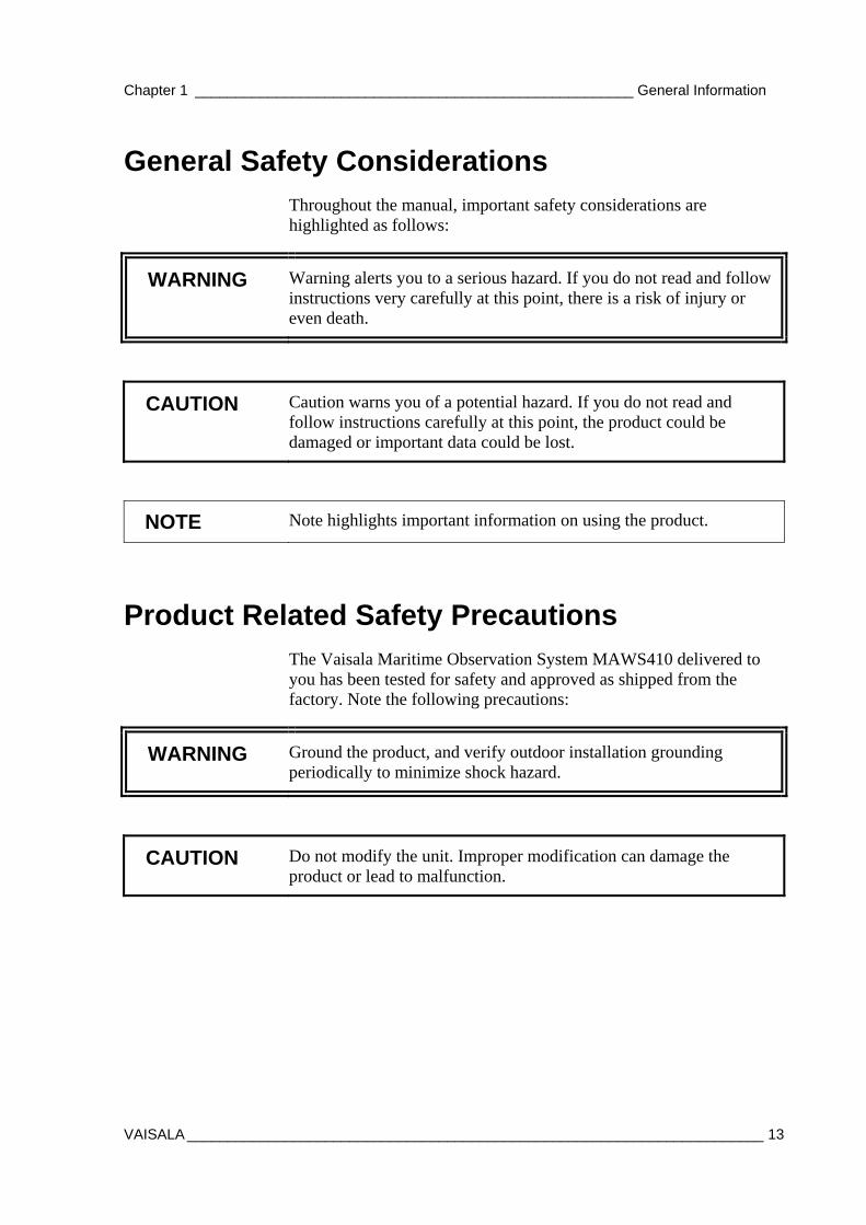
General Safety Considerations Throughout the manual, important safety considerations are highlighted as follows:
WARNING Warning alerts you to a serious hazard. If you do not read and follow instructions very carefully at this point, there is a risk of injury or even death.
CAUTION Caution warns you of a potential hazard. If you do not read and follow instructions carefully at this point, the product could be damaged or important data could be lost.
NOTE Note highlights important information on using the product.
Product Related Safety Precautions The Vaisala Maritime Observation System MAWS410 delivered to you has been tested for safety and approved as shipped from the factory. Note the following precautions:
WARNING Ground the product, and verify outdoor installation grounding periodically to minimize shock hazard.
CAUTION Do not modify the unit. Improper modification can damage the product or lead to malfunction.
USER'S GUIDE____________________________________________________________________
14 __________________________________________________________________ M210891EN-A
ESD Protection Electrostatic Discharge (ESD) can cause immediate or latent damage to electronic circuits. Vaisala products are adequately protected against ESD for their intended use. However, it is possible to damage the product by delivering electrostatic discharges when touching, removing, or inserting any objects inside the equipment housing.
To make sure you are not delivering high static voltages yourself:
- Handle ESD sensitive components on a properly grounded and protected ESD workbench. When this is not possible, ground yourself to the equipment chassis before touching the boards. Ground yourself with a wrist strap and a resistive connection cord. When neither of the above is possible, touch a conductive part of the equipment chassis with your other hand before touching the boards.
- Always hold the boards by the edges and avoid touching the component contacts.
Recycling
Recycle all applicable material.
Dispose of batteries and the unit according to statutory regulations. Do not dispose of with regular household refuse.
Regulatory Compliances The Vaisala Maritime Observation System MAWS410 complies with the following performance, EMC and environmental test standards:
IEC 60945: Maritime navigation and radiocommunication equipment and systems - General requirements - Methods of testing and required test results. 4th edition, 2002-08
Chapter 1 ______________________________________________________ General Information
VAISALA _______________________________________________________________________ 15
Lloyd's Register: LR type approval system, Marine and Offshore Applications, Test Specification Number 1;2002
IEC 60950: Information technology equipment - Safety - Part 1: General requirements
Trademarks Microsoft®, Windows®, Windows NT®, and Windows® 2000 are registered trademarks of Microsoft Corporation in the United States and/or other countries.
License Agreement All rights to any software are held by Vaisala or third parties. The customer is allowed to use the software only to the extent that is provided by the applicable supply contract or Software License Agreement.
Warranty For certain products Vaisala normally gives a limited one-year warranty. Please observe that any such warranty may not be valid in case of damage due to normal wear and tear, exceptional operating conditions, negligent handling or installation, or unauthorized modifications. Please see the applicable supply contract or Conditions of Sale for details of the warranty for each product.

USER'S GUIDE____________________________________________________________________
16 __________________________________________________________________ M210891EN-A
This page intentionally left blank.
Chapter 2 ________________________________________________________ Product Overview
VAISALA _______________________________________________________________________ 17
CHAPTER 2
PRODUCT OVERVIEW
This chapter introduces the product.
Introduction to Vaisala Maritime Observation System MAWS410
The Vaisala Maritime Observation System MAWS410 is weather observation system specifically designed for the rough marine environment. The basic weather parameters measured are wind speed and direction (relative wind, true wind, upwind), atmospheric pressure (QFF, QFE, QNH, pressure tendency), air temperature and humidity (dew point), and water temperature. The sensors are typically installed on a tiltable 3-meter mast.
Built-in algorithms test each measurement to ensure data quality. For each parameter, tests are carried out on the minimum, maximum and step limits, and the different parameters are crosschecked. A built-in testing system also continuously checks the hardware, reporting immediately if a fault occurs. An expansion memory for data storage is also available if not sent to an ancillary system for further use or to be stored on the PC hard drive.
The system processes, displays, stores, and transmits fully automated ship weather reports in the universal FM 13 SHIP (FM 13 XII) and IMMT-3 code formats around the globe, in real-time. These reports can be augmented with visual observations entered prior to transmission. Factors such as cloud type, past weather, weather phenomena, waves and swell, as well as sea-ice and/or ice accretion onboard are added using Vaisala Observation Console software.
The software is also available as a light version: a real- time weather display only without the message sending and editing features.
USER'S GUIDE____________________________________________________________________
18 __________________________________________________________________ M210891EN-A
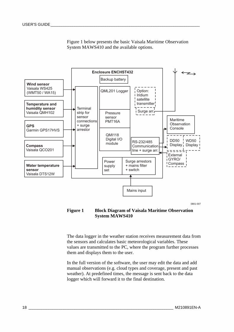
Figure 1 below presents the basic Vaisala Maritime Observation System MAWS410 and the available options.
0801-007
Figure 1 Block Diagram of Vaisala Maritime Observation System MAWS410
The data logger in the weather station receives measurement data from the sensors and calculates basic meteorological variables. These values are transmitted to the PC, where the program further processes them and displays them to the user.
In the full version of the software, the user may edit the data and add manual observations (e.g. cloud types and coverage, present and past weather). At predefined times, the message is sent back to the data logger which will forward it to the final destination.
Chapter 2 ________________________________________________________ Product Overview
VAISALA _______________________________________________________________________ 19
In the light version of the software, only real-time weather data is displayed without the message sending and editing features.
If there is no user present, the application will form a message using the available measurement values and configuration settings and send it forward. Finally, if the PC or its communications to the weather station fail, the weather station will form an automatic back-up message.
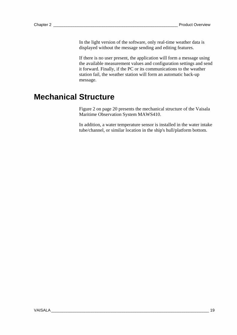
Mechanical Structure Figure 2 on page 20 presents the mechanical structure of the Vaisala Maritime Observation System MAWS410.
In addition, a water temperature sensor is installed in the water intake tube/channel, or similar location in the ship's hull/platform bottom.
USER'S GUIDE____________________________________________________________________
20 __________________________________________________________________ M210891EN-A
0801-008
Figure 2 Mechanical Structure MAWS410
The following numbers refer to Figure 2 above: 1 = Wind sensor 2 Electronic Compass 3 = GPS receiver 4 = Equipment enclosure radiation shield 5 = Equipment enclosure, see Figure 7 on page 24. 6 = Temperature and humidity sensor with radiation shield 7 = Sensor arms 8 = Mast
Chapter 2 ________________________________________________________ Product Overview
VAISALA _______________________________________________________________________ 21
Mast The typical mast used is the 3-meter-tall Vaisala Short Pole Mast DKP203. Also DKP202 and DKP204 can be used. The material of the whole mast is anodized aluminum and the mast is painted white.
Wind Sensor
0801-009
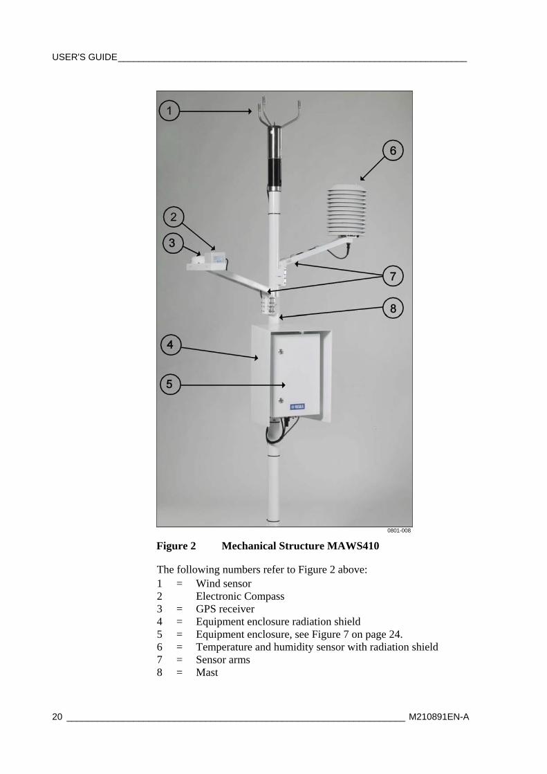
Figure 3 Ultrasonic Wind Sensor WS425
Vaisala Ultrasonic Wind Sensor WS425 uses ultrasound to determine wind speed and wind direction. The sensor has no moving parts, and it is resistant to corrosion and contamination. The sensor has a built-in heater. The elements have a built-in thermostat to switch the heaters on when the transducer head needs it. The sensor is mounted to the mast using a sensor adapter.
The optional WS425 F/G is a special ice-free version of the WS425. With its exceptionally high heating power of 150 W, the WS425 F/G is suitable for most extreme conditions.
The optional WMT50 is Vaisala wind sensor using ultrasound to detect horizontal wind speed and direction.
The optional WA15 mechanical wind sensor consists of a Vaisala Anemometer WAA151, a Vaisala Wind Vane WAV151, an optional crossarm, a power supply, and cabling.

USER'S GUIDE____________________________________________________________________
22 __________________________________________________________________ M210891EN-A
Air Temperature and Humidity Sensor
0801-010
Figure 4 QMH102 and Radiation Shield DTR13
The air temperature and humidity sensor QMH102 is protected under the DTR13 radiation shields. Humidity measurement is based on the highly accurate capacitive thin film polymer sensor HUMICAP®180 and it offers excellent long-term stability in a wide range of environments. Temperature measurement is based on resistive platinum Pt-100 IEC751, 1/3 Class B sensor. Both the humidity and temperature probes are located at the tip of the sensor and are protected by a membrane filter. The sensor is mounted to the mast using a sensor arm.
Compass
0801-011
Figure 5 Vaisala Electronic Compass QCO201
Chapter 2 ________________________________________________________ Product Overview
VAISALA _______________________________________________________________________ 23
Vaisala Electronic Compass QCO201 is a tilt-compensated three-axis compass module. The compass is mounted to the mast in the same sensor arm with the GPS sensor and provides the following information in serial message: heading, pitch, and roll.
Optionally, the ship's own gyro compass can be used.
GPS Sensor
0801-012
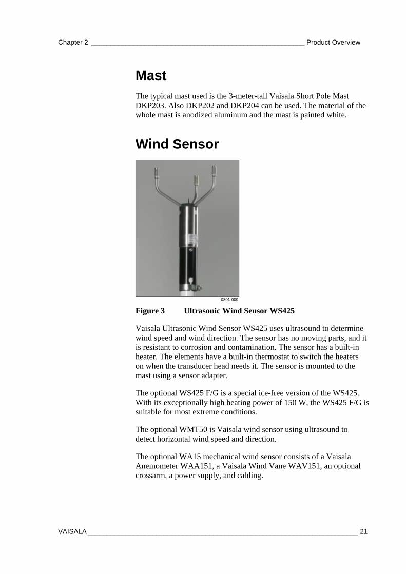
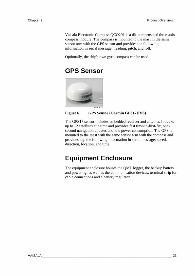
Figure 6 GPS Sensor (Garmin GPS17HVS)
The GPS17 sensor includes embedded receiver and antenna. It tracks up to 12 satellites at a time and provides fast time-to-first-fix, one-second navigation updates and low power consumption. The GPS is mounted to the mast with the same sensor arm with the compass and provides e.g. the following information in serial message: speed, direction, location, and time.
Equipment Enclosure
The equipment enclosure houses the QML logger, the backup battery and powering, as well as the communication devices, terminal strip for cable connections and a battery regulator.
USER'S GUIDE____________________________________________________________________
24 __________________________________________________________________ M210891EN-A
0801-013
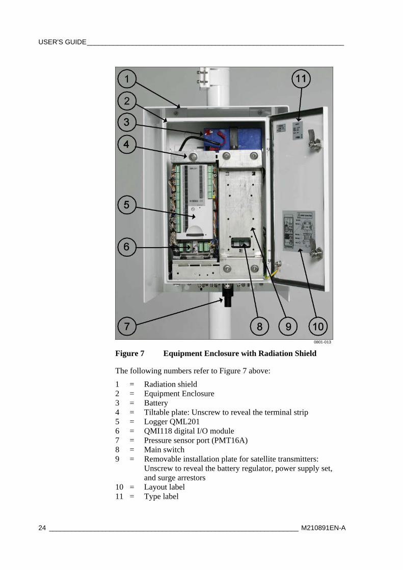
Figure 7 Equipment Enclosure with Radiation Shield
The following numbers refer to Figure 7 above:
1 = Radiation shield 2 = Equipment Enclosure 3 = Battery 4 = Tiltable plate: Unscrew to reveal the terminal strip 5 = Logger QML201 6 = QMI118 digital I/O module 7 = Pressure sensor port (PMT16A) 8 = Main switch 9 = Removable installation plate for satellite transmitters:
Unscrew to reveal the battery regulator, power supply set, and surge arrestors
10 = Layout label 11 = Type label
Chapter 2 ________________________________________________________ Product Overview
VAISALA _______________________________________________________________________ 25
0801-014
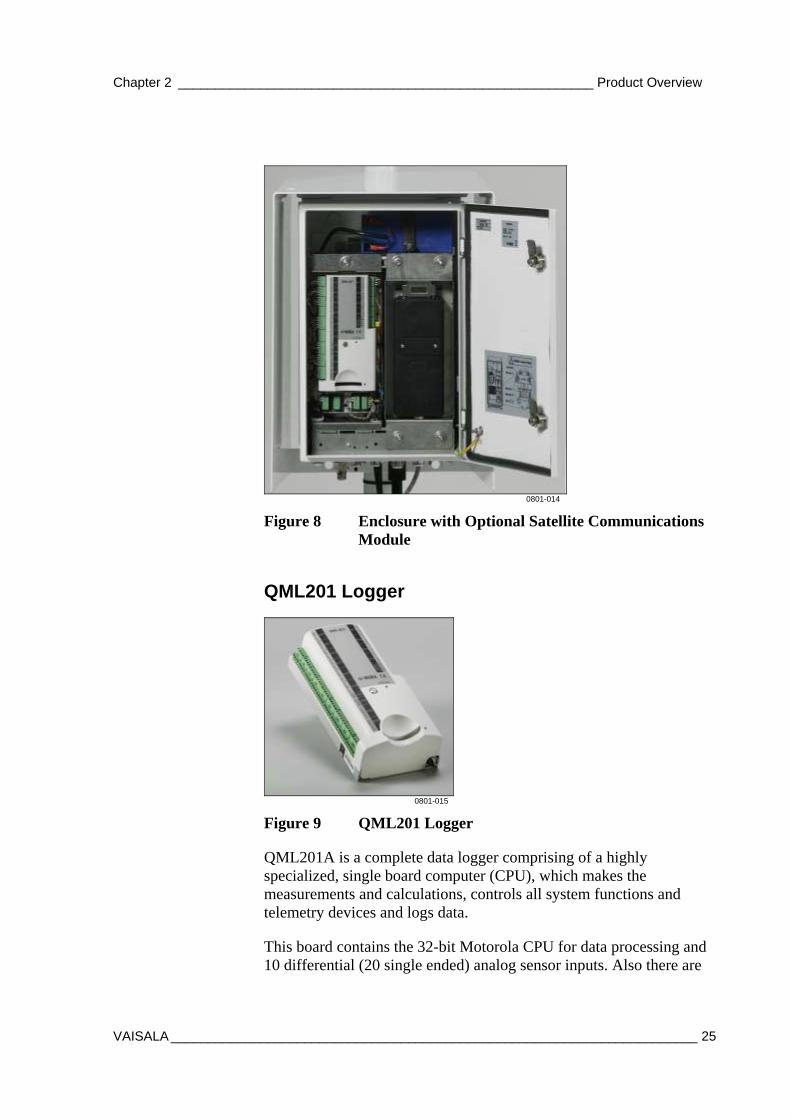
Figure 8 Enclosure with Optional Satellite Communications Module
QML201 Logger
0801-015
Figure 9 QML201 Logger
QML201A is a complete data logger comprising of a highly specialized, single board computer (CPU), which makes the measurements and calculations, controls all system functions and telemetry devices and logs data.
This board contains the 32-bit Motorola CPU for data processing and 10 differential (20 single ended) analog sensor inputs. Also there are

USER'S GUIDE____________________________________________________________________
26 __________________________________________________________________ M210891EN-A
three (3) frequency sensor interfaces, the 16 bits A/D converter, 1.7 Mbytes of secure Flash memory for data logging, RS-232 and RS-485 serial ports, RTC and power supply providing also sensor excitations.
The QML201A has an internal Real-Time-Clock with resolution of 1 second (internally in milliseconds) and stability better than 20 seconds/month. The RTC is backed up with a lithium battery. There also is possibility to read and adjust the RTC using commands issued via serial ports, both locally and remotely e.g. from the central data collection software.
The printed board uses the latest SMT technology and is conformally coated for better protection and reliability also in high humidity environments. Each sensor input has a varistor (VDR) protection against inducted transients. The maintenance terminal connection (RS-232, COM0) has also transzorb diodes in its inputs.
Power Supply Set
0801-046
Figure 10 Power Supply Set
The power supply units are installed inside the equipment enclosure, under the removable installation plate for satellite transmitters. The Mains power supply units ADC8220 and ADC5921 are switching power supplies, which operate from the universal mains (AC) input of 90 to 264 VAC and 45 to 65 Hz.
The ADC8220 output voltage is 15.0 VDC, which is used to power the MAWS system, and as an input to the Battery Regulator QBR101C to charge the back-up battery. The ADC5921 output voltage is 36 VDC, which is used to heat the wind sensors.
Chapter 2 ________________________________________________________ Product Overview
VAISALA _______________________________________________________________________ 27
Surge Arrestors
Data Line Surge Arrestor
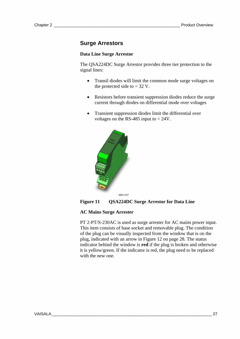
The QSA224DC Surge Arrestor provides three tier protection to the signal lines:
• Transil diodes will limit the common mode surge voltages on the protected side to < 32 V.
• Resistors before transient suppression diodes reduce the surge current through diodes on differential mode over voltages
• Transient suppression diodes limit the differential over voltages on the RS-485 input to < 24V.
0801-047
Figure 11 QSA224DC Surge Arrestor for Data Line
AC Mains Surge Arrester
PT 2-PT/S-230AC is used as surge arrester for AC mains power input. This item consists of base socket and removable plug. The condition of the plug can be visually inspected from the window that is on the plug, indicated with an arrow in Figure 12 on page 28. The status indicator behind the window is red if the plug is broken and otherwise it is yellow/green. If the indicator is red, the plug need to be replaced with the new one.
USER'S GUIDE____________________________________________________________________
28 __________________________________________________________________ M210891EN-A
0801-049
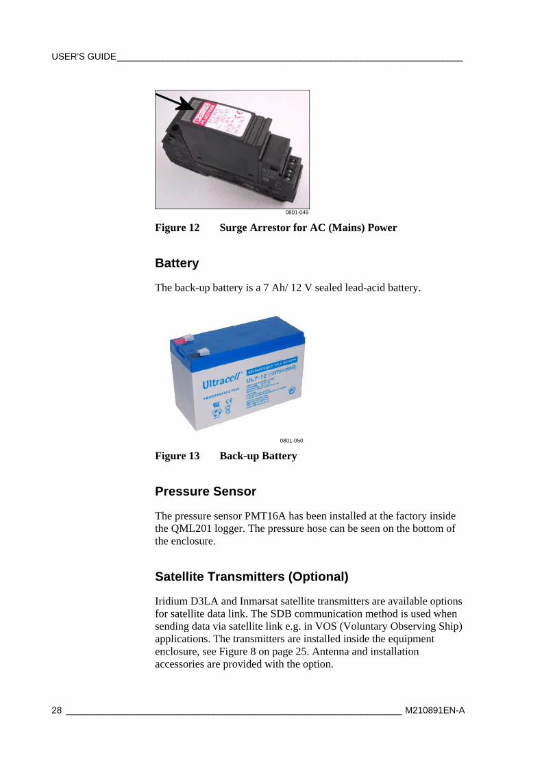
Figure 12 Surge Arrestor for AC (Mains) Power
Battery
The back-up battery is a 7 Ah/ 12 V sealed lead-acid battery.
0801-050
Figure 13 Back-up Battery
Pressure Sensor
The pressure sensor PMT16A has been installed at the factory inside the QML201 logger. The pressure hose can be seen on the bottom of the enclosure.
Satellite Transmitters (Optional)
Iridium D3LA and Inmarsat satellite transmitters are available options for satellite data link. The SDB communication method is used when sending data via satellite link e.g. in VOS (Voluntary Observing Ship) applications. The transmitters are installed inside the equipment enclosure, see Figure 8 on page 25. Antenna and installation accessories are provided with the option.
Chapter 2 ________________________________________________________ Product Overview
VAISALA _______________________________________________________________________ 29
Water Temperature Sensor
0801-016
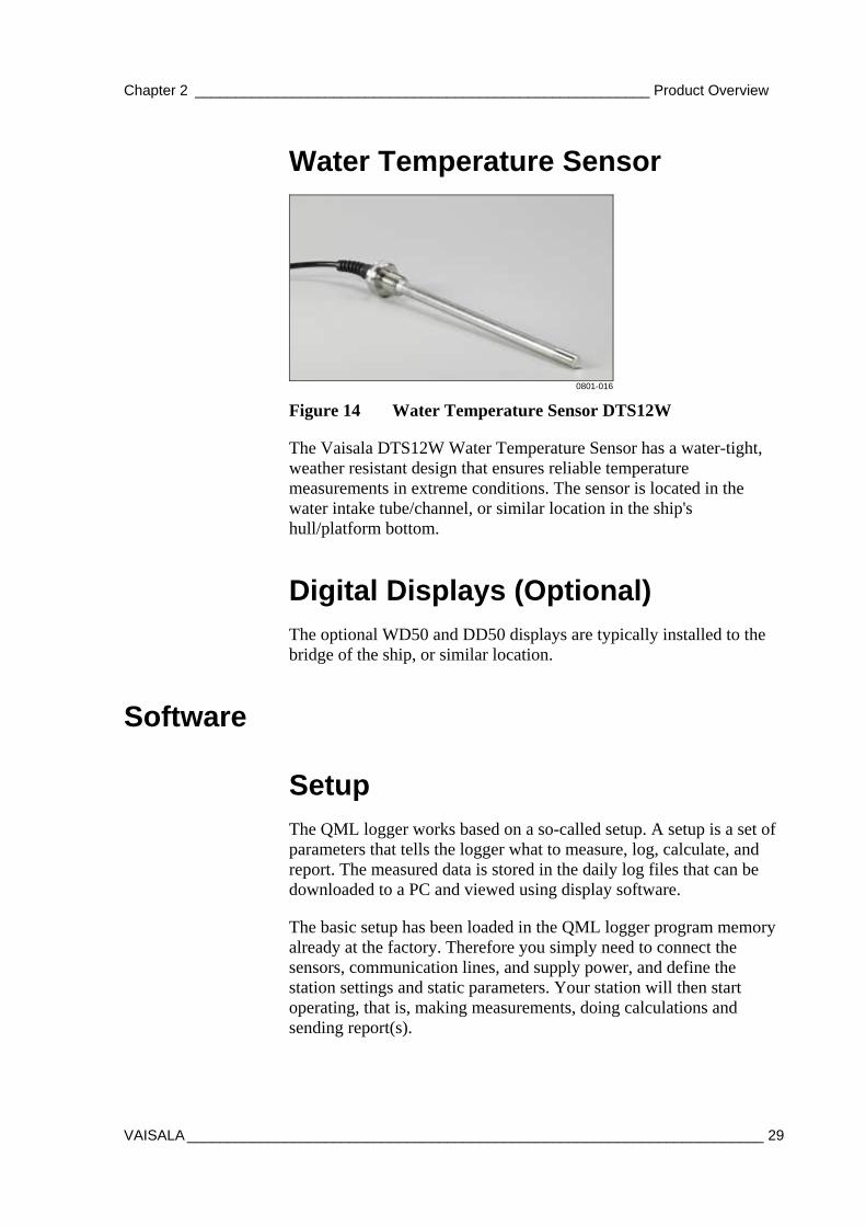
Figure 14 Water Temperature Sensor DTS12W
The Vaisala DTS12W Water Temperature Sensor has a water-tight, weather resistant design that ensures reliable temperature measurements in extreme conditions. The sensor is located in the water intake tube/channel, or similar location in the ship's hull/platform bottom.
Digital Displays (Optional) The optional WD50 and DD50 displays are typically installed to the bridge of the ship, or similar location.
Software
Setup The QML logger works based on a so-called setup. A setup is a set of parameters that tells the logger what to measure, log, calculate, and report. The measured data is stored in the daily log files that can be downloaded to a PC and viewed using display software.
The basic setup has been loaded in the QML logger program memory already at the factory. Therefore you simply need to connect the sensors, communication lines, and supply power, and define the station settings and static parameters. Your station will then start operating, that is, making measurements, doing calculations and sending report(s).
USER'S GUIDE____________________________________________________________________
30 __________________________________________________________________ M210891EN-A
Vaisala HydroMet™ Automatic Weather Station Client Software (AWS Client) Vaisala HydroMet™ Automatic Weather Station Client, or AWS Client for short, is used for working with the QML logger, for example, for setting station-specific parameters to the setup file and for downloading the log files.
Display Software Vaisala Maritime Observation Console is a PC software application for displaying and storing meteorological measurement data. The extended version of the software also includes editing meteorological measurement data and generating standard meteorological messages FM-13 SHIP and IMMT-3. For more information, see Chapter 5, Operating Observation Console, on page 67.
Chapter 3 _______________________________________________________ Installing Hardware
VAISALA _______________________________________________________________________ 31
CHAPTER 3
INSTALLING HARDWARE
This chapter provides you with information that is intended to help you install this product.
Selecting Location Finding a suitable site for the Vaisala Maritime Observation System MAWS410 is important for getting representative ambient measurements.
Mast and Sensor Location When selecting a location for the mast, the location requirements for all the sensors and the enclosure attached to the mast have to be taken into account.
When selecting a location for the mast, pay attention to the following:
- To ensure correct wind measurement, position the mast far from any object that might affect the airflow, such as a revolving radar or an air-conditioning intake.
- To ensure correct compass readings, position the mast sufficiently far away from moving ferrous objects. Moving any ferrous objects (such as the containers on a ship) in the vicinity of the mast causes magnetic field interference for Vaisala Electronic Compass QCO201.
- To ensure correct GPS readings, position the GPS sensor so that it has the clearest possible view of the sky and horizon in all directions. Position the sensor sufficiently far away from radar
USER'S GUIDE____________________________________________________________________
32 __________________________________________________________________ M210891EN-A
equipment, VHF radio antennas and electromagnetic interference from engine components.
- To ensure correct air temperature and relative humidity measurements, avoid the following installation sites: shaded areas, heat sources, direct splashes of sea water, and places that might hold water after rain.
- Allow sufficient clearance for the mast to be tilted and erected, while at the same time providing access to the sensors in the tilted mast and leaving room for the equipment enclosure when tilting.
- Allow sufficient clearance for all the sensors and the enclosure.
Water Temperature Sensor Location Install the water temperature sensor to the water intake tube/channel or similar location in the ship's hull/platform bottom where the sensing element is in direct contact with non-heated surface water.
Preparing Installation
Power Supply and Communication Lines Before assembling the mast the power supply and communication lines must be available. The primary AC (mains) power service must comply with the National Electrical Code (NEC) or equivalent specifications for grounding the primary power service entrance. The AC (mains) must be continuous and without spikes and blackouts. If the AC (mains) voltage is fluctuating more than the given tolerance allows, the AC (mains) voltage stabilizers are recommended.
The following applies to all field cabling:
- Use armored field cables.
- Check the cable core diameter according to maximum allowable drop.
- Route the cables through conduits to the equipment.
- Check cable conduit diameters or use additional termination boxes.

Chapter 3 _______________________________________________________ Installing Hardware
VAISALA _______________________________________________________________________ 33
- Ground the cable shield at both ends.
Always make a detailed cabling and wiring plan. Data transmission lines from the outdoor sites to indoor devices have to be prepared carefully. Also the power supply for the equipment used needs to be planned carefully.
For the cables that connect the indoor components to the outdoor components, it is recommended to use a conduit to protect the cables from damage and moisture. The conduit protects the cables also from the traffic and standing water. Note also that the twist and stress caused by the connectors can damage the cables.
Unpacking Instructions Remove the sensors and other system parts from the containers carefully. It is important to save the containers and all the foam packing for future transporting or shipping.
CAUTION Never move the WS425 Ultrasonic Wind Sensor until it is in its custom shipping container. Otherwise, the warranty will become void.
CAUTION In WS425 a transducer is located at the top of each of the three arms. Be careful not to damage any of the transducers. Dropping the sensor can break or damage the transducer or the arms will bend and they cannot be re-aligned. Damage can also be caused if the transducers are twisted (the transducers are not screwed into the arms).
Contents of the Delivery The mast, its accessories, and the sensors are packed into cartons. The contents of the cartons may vary depending on the selected options. Check the delivery contents against the packing list provided in a plastic folder on the carton or inside the cartons.
USER'S GUIDE____________________________________________________________________
34 __________________________________________________________________ M210891EN-A
Inspecting the Delivery Check the cartons for possible damage. Check that there are no loose parts or connectors before installing the mechanics of the equipment and cabling them. If there has been any damage, contact Vaisala without delay.
Tools Required for Installation In installing the MAWS410 system you need the following tools:
- Welding machine (for mast installation)
- Set of Allen keys
- Adjustable wrenches
- Water level
- Cable ties
- Cable shrouds for protecting the cables
- Laptop computer with Terminal software
- Maintenance cable (QMZ101)

Chapter 3 _______________________________________________________ Installing Hardware
VAISALA _______________________________________________________________________ 35
Installation
Installation Overview Detailed instructions of the installation are provided later in the following sections. The installation contains the following list presents an overview of the installation procedure:
1. Installing the welding plate.
2. Fixing the mast into the welding plate (without erecting the mast yet).
3. Installing the sensors in the mast using the fixing arms provided.
4. Erecting the mast.
5. Installing the enclosure in the mast.
6. Installing water temperature sensor.
7. Cabling and wiring.
8. Checking operation.
9. Defining settings.
10. Calibrating Compass.
11. Routing and protecting cables.
USER'S GUIDE____________________________________________________________________
36 __________________________________________________________________ M210891EN-A
Installing Welding Plate The welding plate is made from structural steel and coated with zinc. To install the welding plate, do the following:
1. Before installing the welding plate, carefully select a suitable location for the mast. See section Selecting Location on page 31.
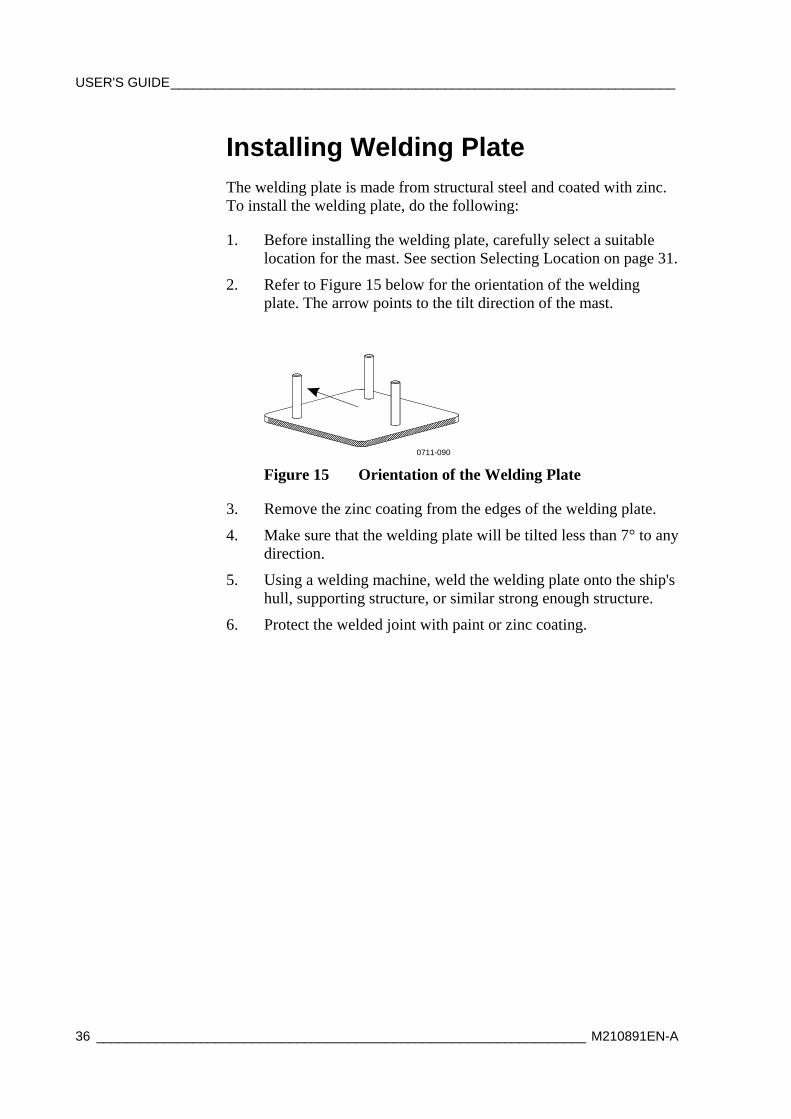
2. Refer to Figure 15 below for the orientation of the welding plate. The arrow points to the tilt direction of the mast.
0711-090
Figure 15 Orientation of the Welding Plate
3. Remove the zinc coating from the edges of the welding plate.
4. Make sure that the welding plate will be tilted less than 7° to any direction.
5. Using a welding machine, weld the welding plate onto the ship's hull, supporting structure, or similar strong enough structure.
6. Protect the welded joint with paint or zinc coating.
Chapter 3 _______________________________________________________ Installing Hardware
VAISALA _______________________________________________________________________ 37
Installing the Mast To install the mast to the welding plate with the tilt division flange, do the following:
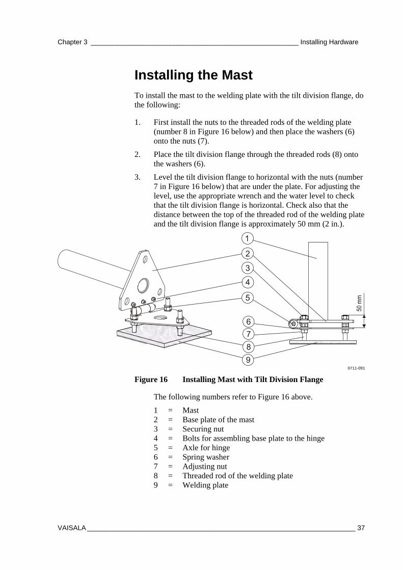
1. First install the nuts to the threaded rods of the welding plate (number 8 in Figure 16 below) and then place the washers (6) onto the nuts (7).
2. Place the tilt division flange through the threaded rods (8) onto the washers (6).
3. Level the tilt division flange to horizontal with the nuts (number 7 in Figure 16 below) that are under the plate. For adjusting the level, use the appropriate wrench and the water level to check that the tilt division flange is horizontal. Check also that the distance between the top of the threaded rod of the welding plate and the tilt division flange is approximately 50 mm (2 in.).
0711-091
Figure 16 Installing Mast with Tilt Division Flange
The following numbers refer to Figure 16 above.
1 = Mast 2 = Base plate of the mast 3 = Securing nut 4 = Bolts for assembling base plate to the hinge 5 = Axle for hinge 6 = Spring washer 7 = Adjusting nut 8 = Threaded rod of the welding plate 9 = Welding plate
USER'S GUIDE____________________________________________________________________
38 __________________________________________________________________ M210891EN-A
Before securing and erecting the mast, install the sensors, see sections below. For instructions for erecting the mast, see section Erecting the Mast on page 44
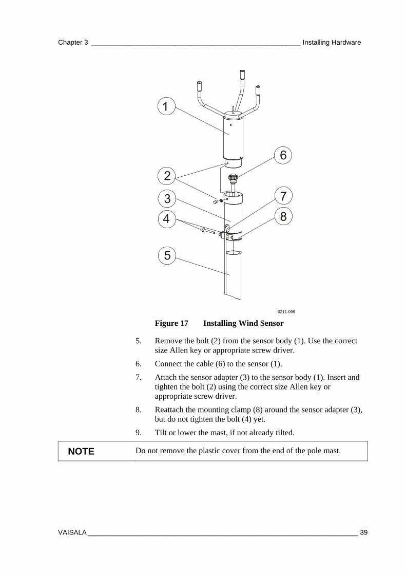
Installing and Aligning Wind Sensor The ultrasonic wind sensor is mounted vertically to the Vaisala sensor adapter with the transducers facing up. To install the wind sensor to the mast with the sensor adapter, follow the procedure below (the numbers refer to Figure 17 on page 39):
1. Remove the mounting clamp (8) from the sensor adapter by loosening the bolt (4).
2. Route the cable through the opening (7) and through the sensor adapter (3). Leave the cable connector (6) outside the adapter.
3. Carefully remove the sensor from the container.
4. Install the bird spike on the top of the sensor.
CAUTION Save the container and all the packaging materials. Always ship the Vaisala Ultrasonic Wind Sensor in its custom shipping container. Otherwise, you will void the warranty.
Chapter 3 _______________________________________________________ Installing Hardware
VAISALA _______________________________________________________________________ 39
0211-099
Figure 17 Installing Wind Sensor
5. Remove the bolt (2) from the sensor body (1). Use the correct size Allen key or appropriate screw driver.
6. Connect the cable (6) to the sensor (1).
7. Attach the sensor adapter (3) to the sensor body (1). Insert and tighten the bolt (2) using the correct size Allen key or appropriate screw driver.
8. Reattach the mounting clamp (8) around the sensor adapter (3), but do not tighten the bolt (4) yet.
9. Tilt or lower the mast, if not already tilted.
NOTE Do not remove the plastic cover from the end of the pole mast.
USER'S GUIDE____________________________________________________________________
40 __________________________________________________________________ M210891EN-A
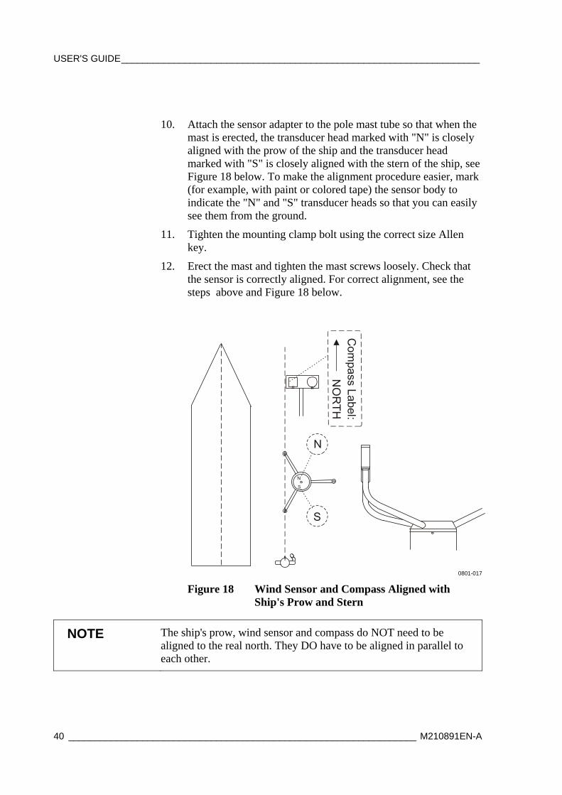
10. Attach the sensor adapter to the pole mast tube so that when the mast is erected, the transducer head marked with "N" is closely aligned with the prow of the ship and the transducer head marked with "S" is closely aligned with the stern of the ship, see Figure 18 below. To make the alignment procedure easier, mark (for example, with paint or colored tape) the sensor body to indicate the "N" and "S" transducer heads so that you can easily see them from the ground.
11. Tighten the mounting clamp bolt using the correct size Allen key.
12. Erect the mast and tighten the mast screws loosely. Check that the sensor is correctly aligned. For correct alignment, see the steps above and Figure 18 below.
0801-017
Figure 18 Wind Sensor and Compass Aligned with Ship's Prow and Stern
NOTE The ship's prow, wind sensor and compass do NOT need to be aligned to the real north. They DO have to be aligned in parallel to each other.
Chapter 3 _______________________________________________________ Installing Hardware
VAISALA _______________________________________________________________________ 41
If the alignment is not correct, do the following:
- Tilt the mast.
- Loosen the mounting clamp at the bottom of the sensor adapter and rotate the sensor so that the transducer heads marked with "N" and "S" are aligned correctly.
- Tighten the mounting clamp.
- Erect the mast and check the alignment again until the sensor is correctly aligned with the required accuracy.
13. Tilt the mast and attach the wind sensor cables to the mast with the cable ties.
For installation instructions of the optional wind sensor WMT50/WA15, refer to the sensor manuals. However, align the sensor to the ship's prow, as described above.
Installing and Aligning GPS Receiver and Compass Install the GPS receiver (Garmin GPS17HS) and Vaisala compass QCO201 to the mast by doing the following:
1. Install the sensor arm (DKPFIXP44) to the mast so that when the compass is mounted, its "NORTH" marking will be closely aligned with the ship's prow and the wind sensor "N" - "S" direction. See Figure 18 on page 40 and Figure 20 on page 42.
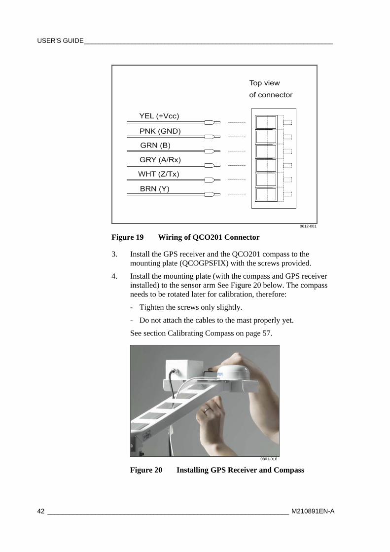
2. When applicable, remove the M12 connector from the QCO201 compass and replace it with the cable gland included in the delivery. Connect the compass cable to the connector inside the QCO201 as shown in Figure 19 on page 42.
USER'S GUIDE____________________________________________________________________
42 __________________________________________________________________ M210891EN-A
0612-001
Figure 19 Wiring of QCO201 Connector
3. Install the GPS receiver and the QCO201 compass to the mounting plate (QCOGPSFIX) with the screws provided.
4. Install the mounting plate (with the compass and GPS receiver installed) to the sensor arm See Figure 20 below. The compass needs to be rotated later for calibration, therefore:
- Tighten the screws only slightly.
- Do not attach the cables to the mast properly yet.
See section Calibrating Compass on page 57.
0801-018
Figure 20 Installing GPS Receiver and Compass
Chapter 3 _______________________________________________________ Installing Hardware
VAISALA _______________________________________________________________________ 43
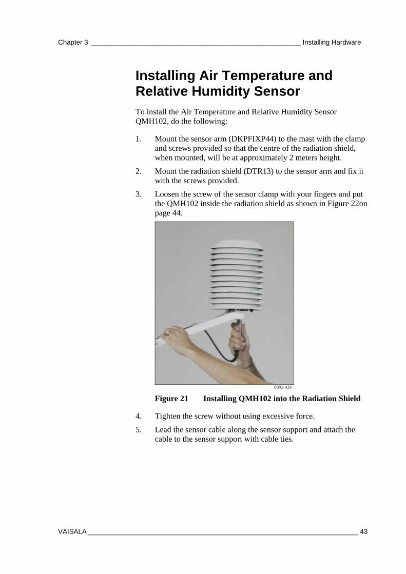
Installing Air Temperature and Relative Humidity Sensor To install the Air Temperature and Relative Humidity Sensor QMH102, do the following:
1. Mount the sensor arm (DKPFIXP44) to the mast with the clamp and screws provided so that the centre of the radiation shield, when mounted, will be at approximately 2 meters height.
2. Mount the radiation shield (DTR13) to the sensor arm and fix it with the screws provided.
3. Loosen the screw of the sensor clamp with your fingers and put the QMH102 inside the radiation shield as shown in Figure 22on page 44.
0801-019
Figure 21 Installing QMH102 into the Radiation Shield
4. Tighten the screw without using excessive force.
5. Lead the sensor cable along the sensor support and attach the cable to the sensor support with cable ties.
USER'S GUIDE____________________________________________________________________
44 __________________________________________________________________ M210891EN-A
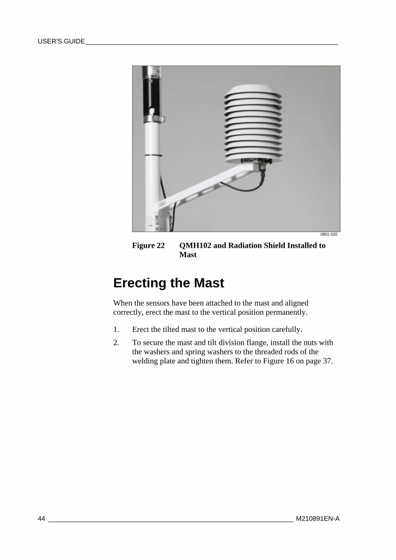
0801-020
Figure 22 QMH102 and Radiation Shield Installed to Mast
Erecting the Mast When the sensors have been attached to the mast and aligned correctly, erect the mast to the vertical position permanently.
1. Erect the tilted mast to the vertical position carefully.
2. To secure the mast and tilt division flange, install the nuts with the washers and spring washers to the threaded rods of the welding plate and tighten them. Refer to Figure 16 on page 37.
Chapter 3 _______________________________________________________ Installing Hardware
VAISALA _______________________________________________________________________ 45
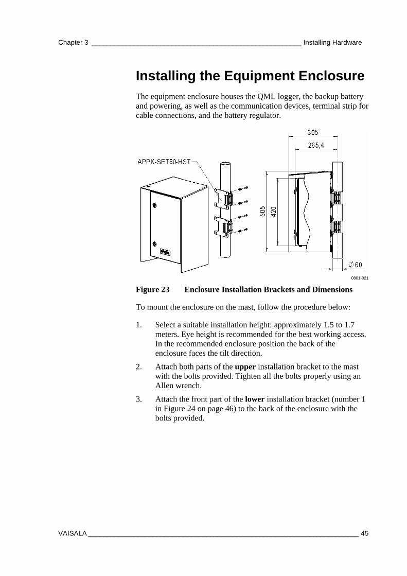
Installing the Equipment Enclosure The equipment enclosure houses the QML logger, the backup battery and powering, as well as the communication devices, terminal strip for cable connections, and the battery regulator.
0801-021
Figure 23 Enclosure Installation Brackets and Dimensions
To mount the enclosure on the mast, follow the procedure below:
1. Select a suitable installation height: approximately 1.5 to 1.7 meters. Eye height is recommended for the best working access. In the recommended enclosure position the back of the enclosure faces the tilt direction.
2. Attach both parts of the upper installation bracket to the mast with the bolts provided. Tighten all the bolts properly using an Allen wrench.
3. Attach the front part of the lower installation bracket (number 1 in Figure 24 on page 46) to the back of the enclosure with the bolts provided.
USER'S GUIDE____________________________________________________________________
46 __________________________________________________________________ M210891EN-A
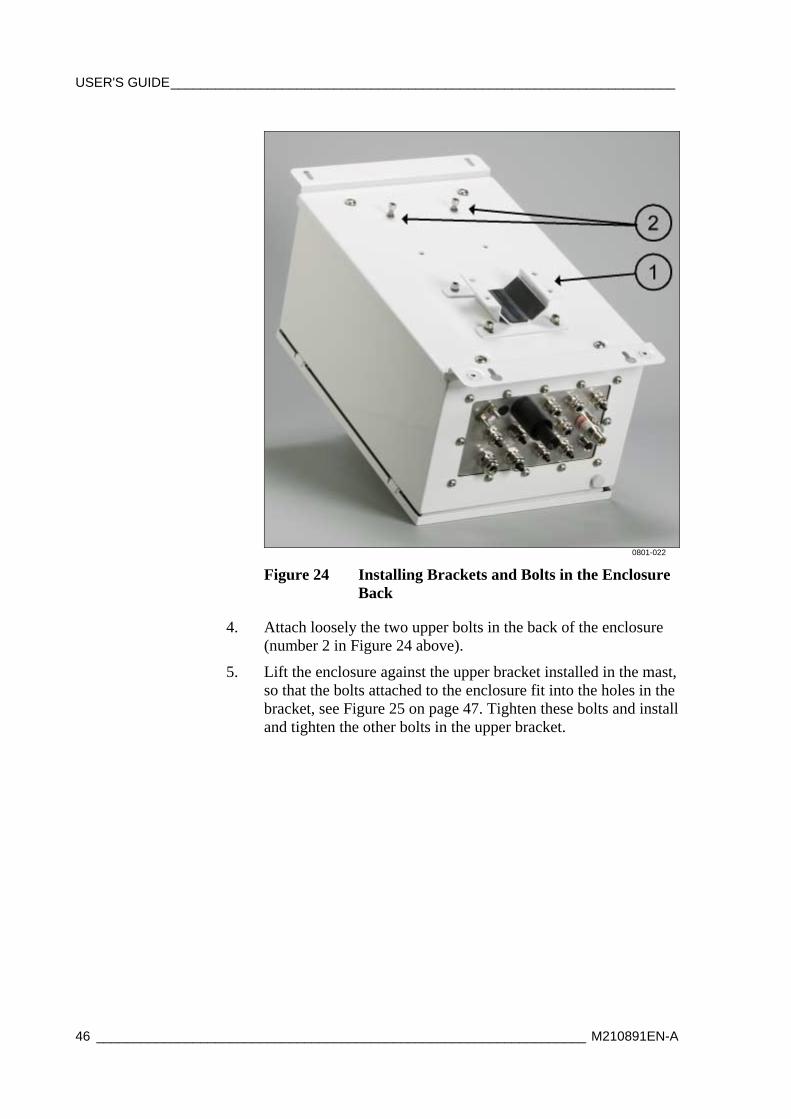
0801-022
Figure 24 Installing Brackets and Bolts in the Enclosure Back
4. Attach loosely the two upper bolts in the back of the enclosure (number 2 in Figure 24 above).
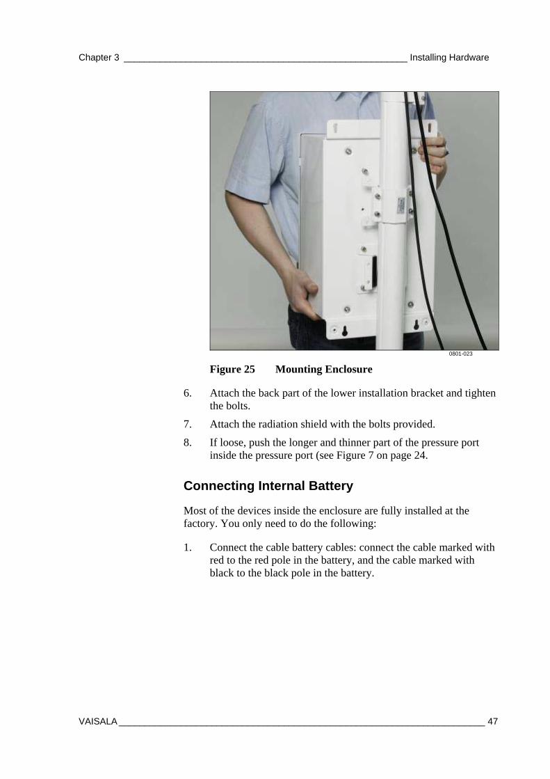
5. Lift the enclosure against the upper bracket installed in the mast, so that the bolts attached to the enclosure fit into the holes in the bracket, see Figure 25 on page 47. Tighten these bolts and install and tighten the other bolts in the upper bracket.
Chapter 3 _______________________________________________________ Installing Hardware
VAISALA _______________________________________________________________________ 47
0801-023
Figure 25 Mounting Enclosure
6. Attach the back part of the lower installation bracket and tighten the bolts.
7. Attach the radiation shield with the bolts provided.
8. If loose, push the longer and thinner part of the pressure port inside the pressure port (see Figure 7 on page 24.
Connecting Internal Battery
Most of the devices inside the enclosure are fully installed at the factory. You only need to do the following:
1. Connect the cable battery cables: connect the cable marked with red to the red pole in the battery, and the cable marked with black to the black pole in the battery.
USER'S GUIDE____________________________________________________________________
48 __________________________________________________________________ M210891EN-A
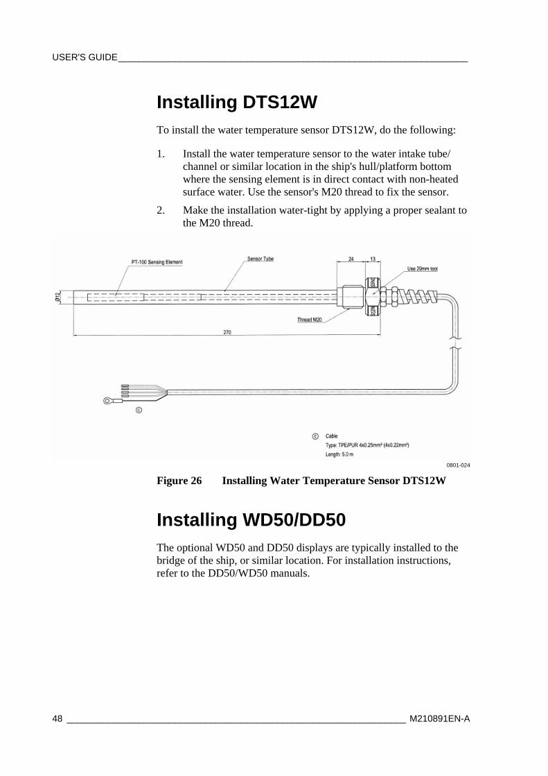
Installing DTS12W To install the water temperature sensor DTS12W, do the following:
1. Install the water temperature sensor to the water intake tube/ channel or similar location in the ship's hull/platform bottom where the sensing element is in direct contact with non-heated surface water. Use the sensor's M20 thread to fix the sensor.
2. Make the installation water-tight by applying a proper sealant to the M20 thread.
0801-024
Figure 26 Installing Water Temperature Sensor DTS12W
Installing WD50/DD50
The optional WD50 and DD50 displays are typically installed to the bridge of the ship, or similar location. For installation instructions, refer to the DD50/WD50 manuals.

Chapter 3 _______________________________________________________ Installing Hardware
VAISALA _______________________________________________________________________ 49
Cabling and Wiring
Connecting Grounding Cable
WARNING A long cable between different units (sensors, transmitters, power supplies, and displays) can cause a life-threatening surge voltage, if a lightning strike occurs close by. Always ground the mast equipment case close to the mast with a short and low resistance cable.
To connect the grounding cable, do the following:
1. Using the grounding cable included in the delivery, connect the equipment grounding cable to the main grounding point located underneath the system enclosure, see Figure 27 below. Strip 10-15 mm sheath from the cable end and solder it, or use cable ferrule.
0801-025
Figure 27 Connecting Grounding Cable to the Enclosure
2. Connect the other end of the cable to a grounded location in the ship's frame using an applicable adapter, cable lug, or similar.
Connecting Sensor Cables
To connect the sensor cables, do the following:
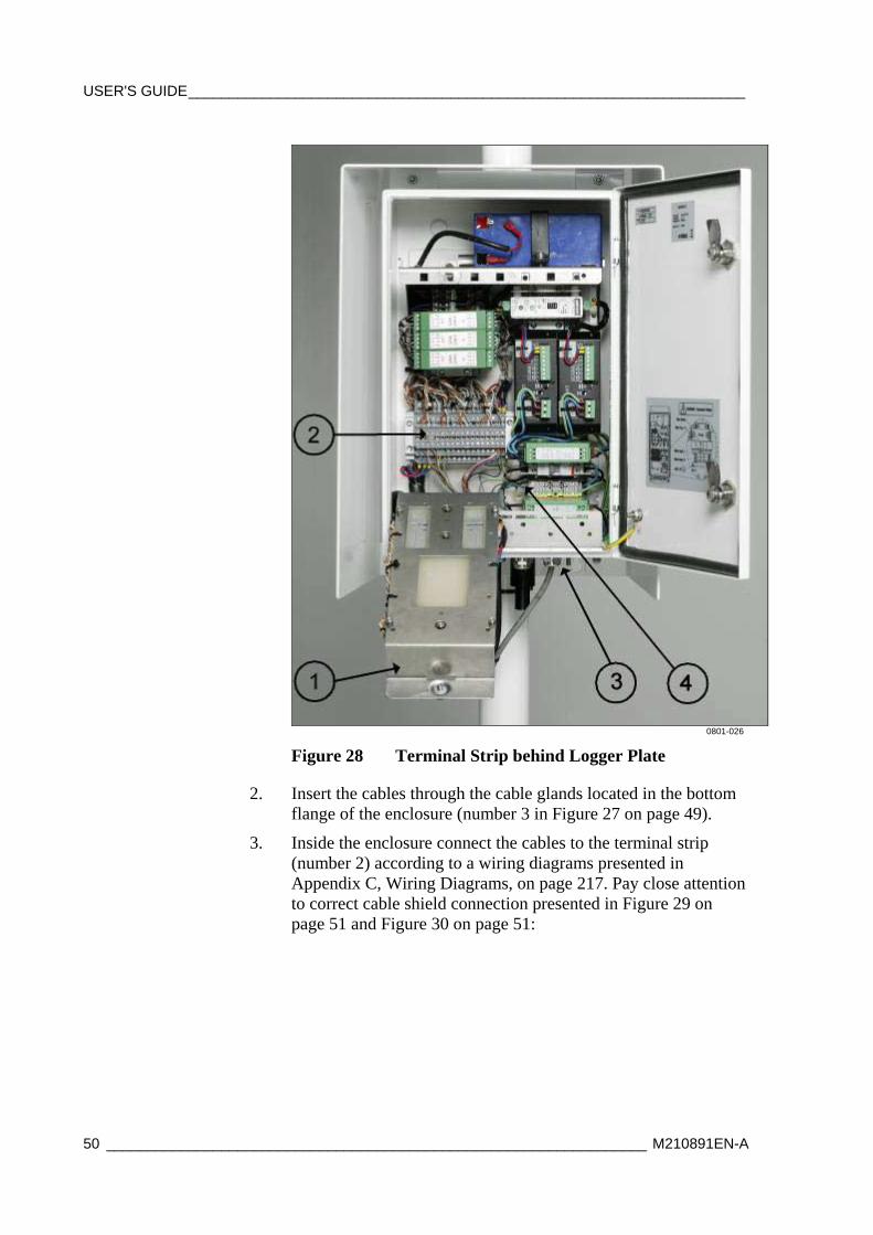
1. Unscrew the installation plates (number 1 in Figure 28 on page 50) and flip them down to see the terminal strips (number 2 in Figure 28 on page 50).
USER'S GUIDE____________________________________________________________________
50 __________________________________________________________________ M210891EN-A
0801-026
Figure 28 Terminal Strip behind Logger Plate
2. Insert the cables through the cable glands located in the bottom flange of the enclosure (number 3 in Figure 27 on page 49).
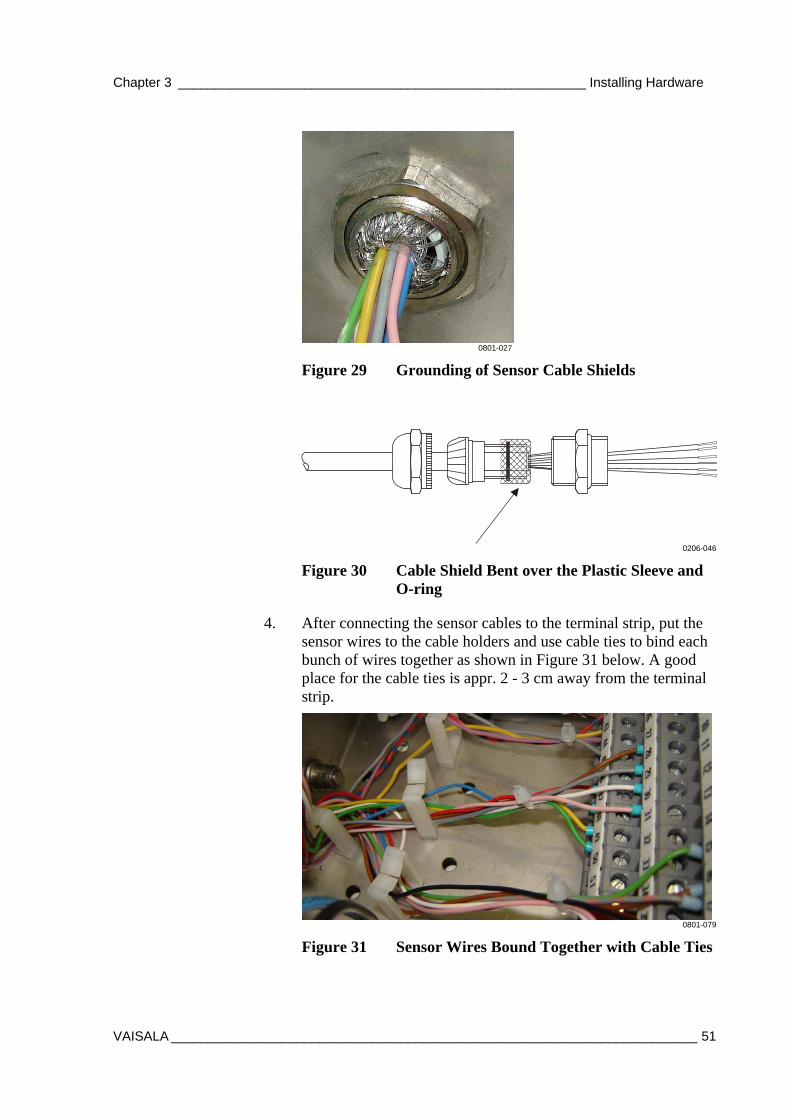
3. Inside the enclosure connect the cables to the terminal strip (number 2) according to a wiring diagrams presented in Appendix C, Wiring Diagrams, on page 217. Pay close attention to correct cable shield connection presented in Figure 29 on page 51 and Figure 30 on page 51:
Chapter 3 _______________________________________________________ Installing Hardware
VAISALA _______________________________________________________________________ 51
0801-027
Figure 29 Grounding of Sensor Cable Shields
0206-046
Figure 30 Cable Shield Bent over the Plastic Sleeve and O-ring
4. After connecting the sensor cables to the terminal strip, put the sensor wires to the cable holders and use cable ties to bind each bunch of wires together as shown in Figure 31 below. A good place for the cable ties is appr. 2 - 3 cm away from the terminal strip.
0801-079
Figure 31 Sensor Wires Bound Together with Cable Ties
USER'S GUIDE____________________________________________________________________
52 __________________________________________________________________ M210891EN-A
5. For protection, spray the cable glands on the bottom of the enclosure with the insulation/protection spray provided.
Connecting AC Power
The mains (AC) cable is not included in the delivery. A mains cable with the minimum external diameter of 3 x 1,5 mm2 can be used.
1. Insert the mains cable inside the enclosure through any of the cable glands located close to the surge arrestor.
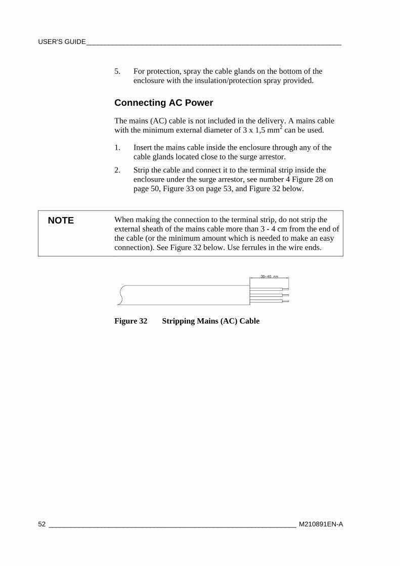
2. Strip the cable and connect it to the terminal strip inside the enclosure under the surge arrestor, see number 4 Figure 28 on page 50, Figure 33 on page 53, and Figure 32 below.
NOTE When making the connection to the terminal strip, do not strip the external sheath of the mains cable more than 3 - 4 cm from the end of the cable (or the minimum amount which is needed to make an easy connection). See Figure 32 below. Use ferrules in the wire ends.
Figure 32 Stripping Mains (AC) Cable
Chapter 3 _______________________________________________________ Installing Hardware
VAISALA _______________________________________________________________________ 53
00801-028
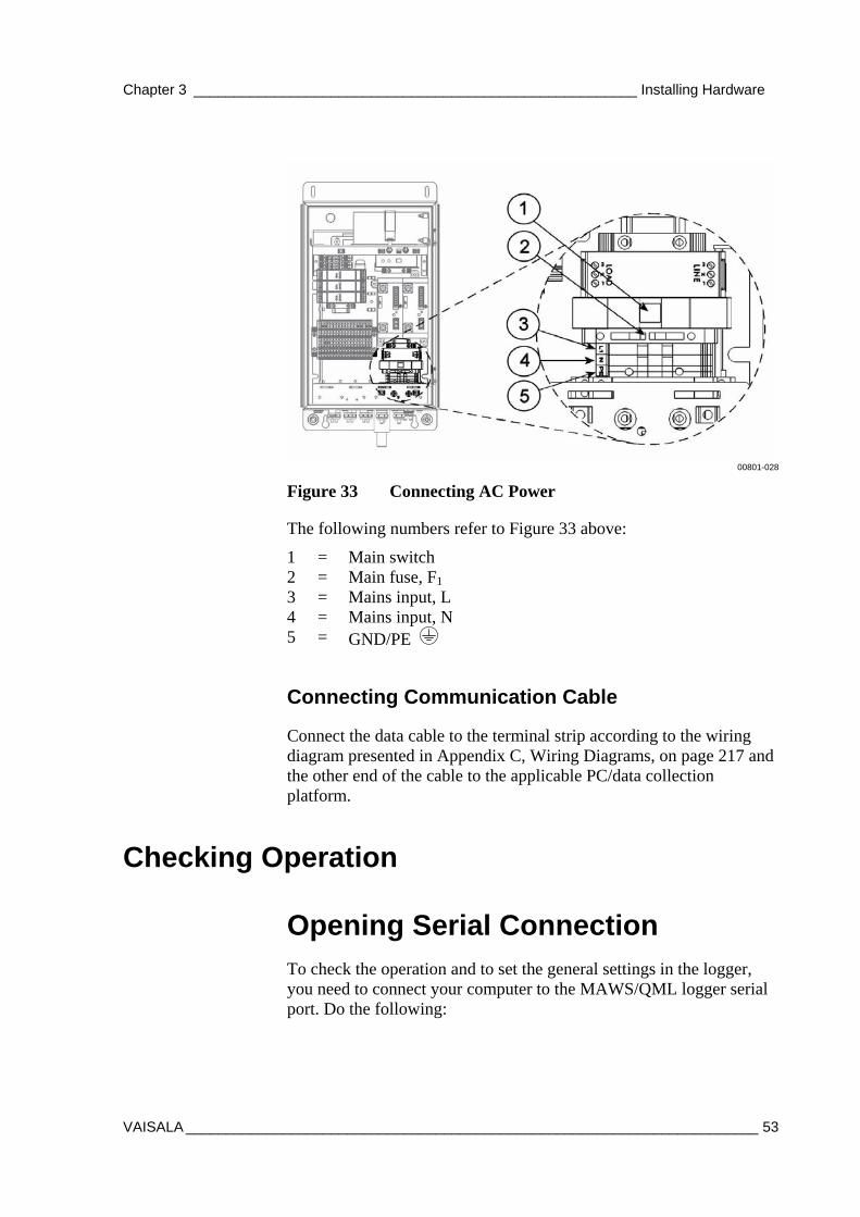
Figure 33 Connecting AC Power
The following numbers refer to Figure 33 above:
1 = Main switch 2 = Main fuse, F1 3 = Mains input, L 4 = Mains input, N 5 = GND/PE
Connecting Communication Cable
Connect the data cable to the terminal strip according to the wiring diagram presented in Appendix C, Wiring Diagrams, on page 217 and the other end of the cable to the applicable PC/data collection platform.
Checking Operation
Opening Serial Connection
To check the operation and to set the general settings in the logger, you need to connect your computer to the MAWS/QML logger serial port. Do the following:
USER'S GUIDE____________________________________________________________________
54 __________________________________________________________________ M210891EN-A
1. Turn the power on from the main switch inside the enclosure. See Figure 7 on page 24.
2. Connect the provided terminal cable to the maintenance terminal connector on the bottom flange of the enclosure and to an available COM port on your PC.
3. Start the Terminal program on your PC.
4. Set the communication parameters to: 9600, N, 8, 1.
5. Enter the command open.
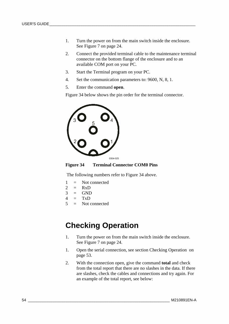
Figure 34 below shows the pin order for the terminal connector.
0304-025
Figure 34 Terminal Connector COM0 Pins
The following numbers refer to Figure 34 above.
1 = Not connected 2 = RxD 3 = GND 4 = TxD 5 = Not connected
Checking Operation 1. Turn the power on from the main switch inside the enclosure.
See Figure 7 on page 24.
1. Open the serial connection, see section Checking Operation on page 53.
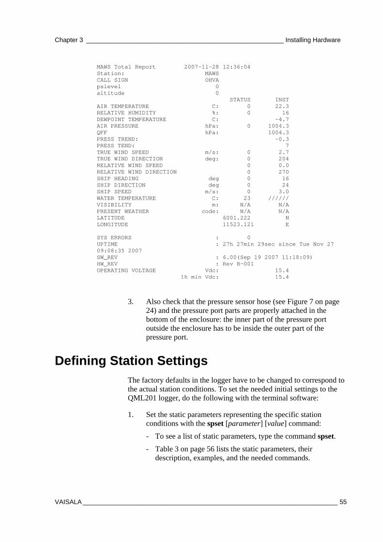
2. With the connection open, give the command total and check from the total report that there are no slashes in the data. If there are slashes, check the cables and connections and try again. For an example of the total report, see below:
Chapter 3 _______________________________________________________ Installing Hardware
VAISALA _______________________________________________________________________ 55
MAWS Total Report 2007-11-28 12:36:04 Station: MAWS CALL SIGN OHVA pslevel 0 altitude 0 STATUS INST AIR TEMPERATURE C: 0 22.3 RELATIVE HUMIDITY %: 0 16 DEWPOINT TEMPERATURE C: -4.7 AIR PRESSURE hPa: 0 1004.3 QFF hPa: 1004.3 PRESS TREND: -0.3 PRESS TEND: 7 TRUE WIND SPEED m/s: 0 2.7 TRUE WIND DIRECTION deg: 0 204 RELATIVE WIND SPEED 0 0.0 RELATIVE WIND DIRECTION 0 270 SHIP HEADING deg 0 16 SHIP DIRECTION deg 0 24 SHIP SPEED m/s: 0 3.0 WATER TEMPERATURE C: 23 ////// VISIBILITY m: N/A N/A PRESENT WEATHER code: N/A N/A LATITUDE 6001.222 N LONGITUDE 11523.121 E SYS ERRORS : 0 UPTIME : 27h 27min 29sec since Tue Nov 27 09:08:35 2007 SW_REV : 6.00(Sep 19 2007 11:18:09) HW_REV : Rev B-001 OPERATING VOLTAGE Vdc: 15.4 1h min Vdc: 15.4
3. Also check that the pressure sensor hose (see Figure 7 on page 24) and the pressure port parts are properly attached in the bottom of the enclosure: the inner part of the pressure port outside the enclosure has to be inside the outer part of the pressure port.
Defining Station Settings The factory defaults in the logger have to be changed to correspond to the actual station conditions. To set the needed initial settings to the QML201 logger, do the following with the terminal software:
1. Set the static parameters representing the specific station conditions with the spset [parameter] [value] command:
- To see a list of static parameters, type the command spset.
- Table 3 on page 56 lists the static parameters, their description, examples, and the needed commands.
USER'S GUIDE____________________________________________________________________
56 __________________________________________________________________ M210891EN-A
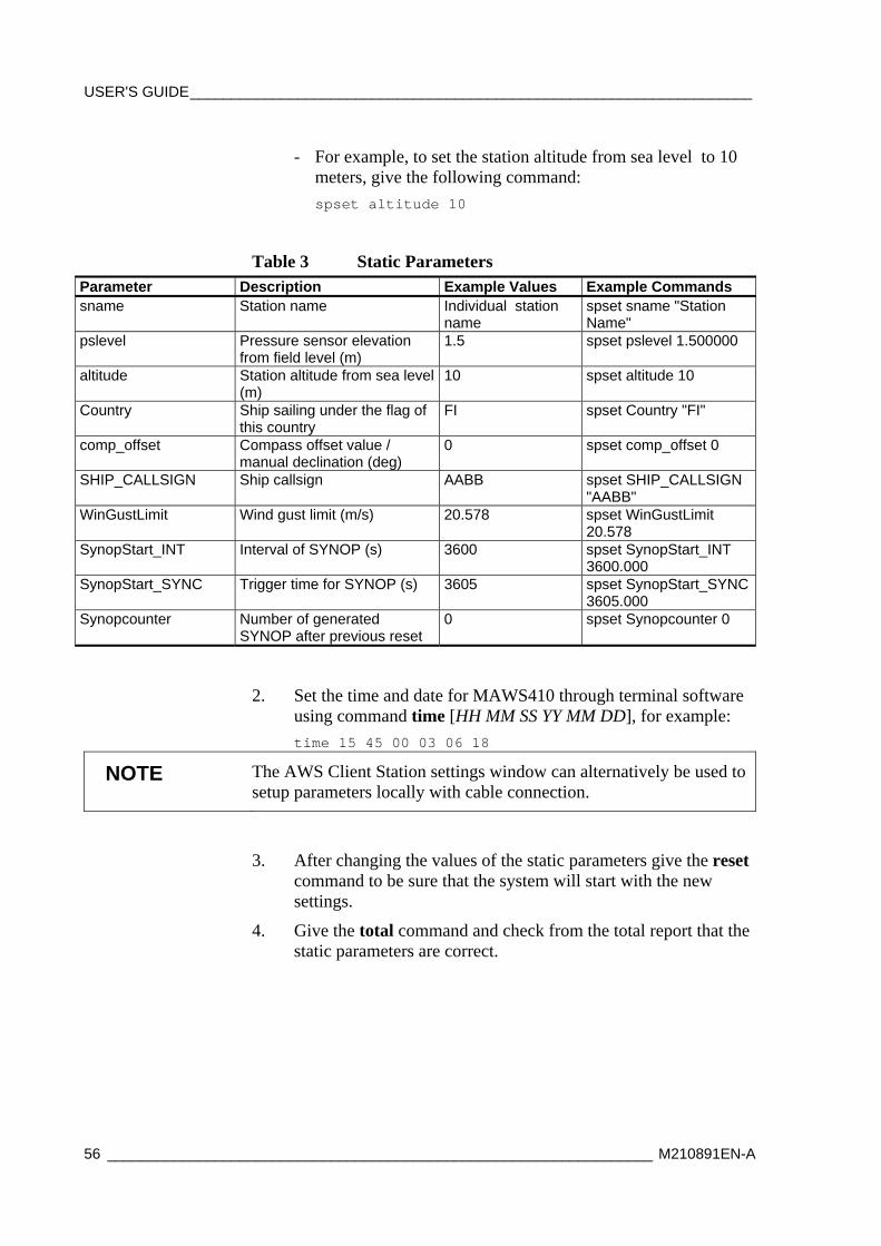
- For example, to set the station altitude from sea level to 10 meters, give the following command: spset altitude 10
Table 3 Static Parameters Parameter Description Example Values Example Commands sname Station name Individual station
name spset sname "Station Name"
pslevel Pressure sensor elevation from field level (m)
1.5 spset pslevel 1.500000
altitude Station altitude from sea level (m)
10
spset altitude 10
Country Ship sailing under the flag of this country
FI spset Country "FI"
comp_offset Compass offset value / manual declination (deg)
0 spset comp_offset 0
SHIP_CALLSIGN Ship callsign AABB spset SHIP_CALLSIGN "AABB"
WinGustLimit Wind gust limit (m/s) 20.578 spset WinGustLimit 20.578
SynopStart_INT Interval of SYNOP (s) 3600 spset SynopStart_INT 3600.000
SynopStart_SYNC Trigger time for SYNOP (s) 3605 spset SynopStart_SYNC 3605.000
Synopcounter Number of generated SYNOP after previous reset
0 spset Synopcounter 0
2. Set the time and date for MAWS410 through terminal software using command time [HH MM SS YY MM DD], for example: time 15 45 00 03 06 18
NOTE The AWS Client Station settings window can alternatively be used to setup parameters locally with cable connection.
3. After changing the values of the static parameters give the reset command to be sure that the system will start with the new settings.
4. Give the total command and check from the total report that the static parameters are correct.
Chapter 3 _______________________________________________________ Installing Hardware
VAISALA _______________________________________________________________________ 57
Calibrating Compass The calibration of QCO201 is in essential role when reliable heading data is needed. If the compass is left uncalibrated after installation, the heading information might be unreliable.
Vaisala Electronic Compass QCO201 determines the heading angle by sensing the earth's magnetic field. All ferromagnetic materials and objects which are close to the compass cause anomalies to earth's magnetic field. These magnetic anomalies have a direct effect to the compass heading output. Therefore whenever the compass is installed or moved to the new location, it must be calibrated.
During the calibration, the compass tries to take as many different data points from the measured magnetic field as possible to determine the magnetic anomalies. These datapoints are saved to the nonvolatile memory and are used to compensate the effect of the magnetic anomalies to the heading output.
Before Calibration
Make sure of the following before calibrating the compass:
- MAWS410 system is completely installed and working prior to compass calibration. See section Checking Operation on page 54.
- The installation plate where QCO201 is attached must be completely loose (also approximately 0.5 m of loose wire is needed) before starting the calibration.
- Make sure that the compass is working properly and giving readings.
Calibration Procedure
NOTE Read the calibration instruction thoroughly before attempting the calibration procedure.
1. Open the service connection to MAWS410 with a terminal program.
2. Issue the command: calib ON. At least the latter part of command must be in CAPITAL letters.
USER'S GUIDE____________________________________________________________________
58 __________________________________________________________________ M210891EN-A
3. Wait until the text "Compass in calibration mode" appears to the terminal. If this text does not appear in 10 seconds, rotate the compass slightly and the text should appear.
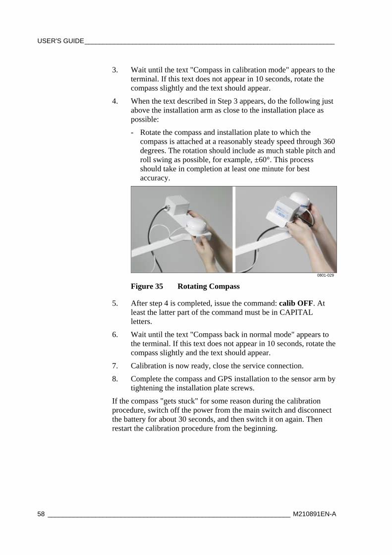
4. When the text described in Step 3 appears, do the following just above the installation arm as close to the installation place as possible:
- Rotate the compass and installation plate to which the compass is attached at a reasonably steady speed through 360 degrees. The rotation should include as much stable pitch and roll swing as possible, for example, ±60°. This process should take in completion at least one minute for best accuracy.
0801-029
Figure 35 Rotating Compass
5. After step 4 is completed, issue the command: calib OFF. At least the latter part of the command must be in CAPITAL letters.
6. Wait until the text "Compass back in normal mode" appears to the terminal. If this text does not appear in 10 seconds, rotate the compass slightly and the text should appear.
7. Calibration is now ready, close the service connection.
8. Complete the compass and GPS installation to the sensor arm by tightening the installation plate screws.
If the compass "gets stuck" for some reason during the calibration procedure, switch off the power from the main switch and disconnect the battery for about 30 seconds, and then switch it on again. Then restart the calibration procedure from the beginning.
Chapter 3 _______________________________________________________ Installing Hardware
VAISALA _______________________________________________________________________ 59
Routing the Device Cables Route the device cables down from the top of the mast and attach the cables to the mast with the cable ties. The recommended distance between the cable ties is from 30 to 40 cm (11 to 16 in.).
Securing and Protecting the Cables Protect the cables properly, especially when the cables are attached to the ship floor and may get walked on.
Near the hinge you should protect the cables with the provided protective spiral to avoid possible damage to cables when the mast is tilted and erected.
Closing Enclosure Close the equipment enclosure door and store the enclosure key in a safe place.
Disassembly for Transportation The sensors come in custom shipping containers. The sensors must be carefully repacked in the containers when preparing for transportation. It is important to save the containers and all the foam packing for future transporting or shipping.
CAUTION Never transport the WS425 Ultrasonic Wind Sensor until it is in its custom shipping container. Otherwise, the warranty will become void.
CAUTION In the WS425 Ultrasonic Wind Sensor a transducer is located at the top of each of the three arms. Be careful not to damage any of the transducers. Dropping the sensor can break or damage the transducer or the arms will bend and they cannot be re-aligned. Damage can also be caused if the transducers are twisted (the transducers are not screwed into the arms).

USER'S GUIDE____________________________________________________________________
60 __________________________________________________________________ M210891EN-A
This page intentionally left blank.

Chapter 4 _______________________________________________________ Installing Software
VAISALA _______________________________________________________________________ 61
CHAPTER 4
INSTALLING SOFTWARE
This chapter gives instructions for installing the PC software for Vaisala Maritime System.
Minimum System Requirements The application can be run in a Windows XP/2000/2003 PC with at least 512 MB of free memory, 2.0 GHz processor, and a CD drive. The application requires less than 10 MB of free hard disk space when operational.
Vaisala Maritime Observation Console is designed to support message generation for one weather station only. It cannot be used to generate or edit messages from several stations.
Recommended Operating System Settings
To guarantee the best operation, the following settings should be checked from the Control Panel before installing software.
NOTE These settings apply to Window XP operating system. In other operating systems, the instructions may be different.
User Account The application must be installed to a user account that has administrative rights on the computer.
USER'S GUIDE____________________________________________________________________
62 __________________________________________________________________ M210891EN-A
System Time Usually, the universal coordinated time (UTC) time is used instead of local time in all meteorological reports. It is recommended that the PC will be set to UTC time zone, too.
NOTE The AWS and PC clocks have to be on the same time zone.
1. From Control Panel, select Date and Time.
2. Verify that the computer clock is set to UTC time.
3. Check that Time Zone is either Casablanca/ Monrovia or GMT time without the daylight savings option.
Network Options Unless otherwise specified, use the default network settings. However, check the following:
1. In Control Panel, select Network Connections.
2. Select Internet Protocol.
3. Click Properties.
4. In the dialog that opens, make sure that the Obtain IP address automatically option has been selected. If your network administrator has provided the PC with a specific IP address, subnet mask, and default gateway, ensure that they are correctly configured.
5. See also Chapter 6, Observation Console Administrator's Guide, on page 81, regarding the configuration and testing of communications with the automatic weather station.
Keyboard If the computer keyboard contains special characters that do not appear on the screen, select local keyboard from Control Panel/ Regional and Language Options / Languages / Details.
Chapter 4 _______________________________________________________ Installing Software
VAISALA _______________________________________________________________________ 63
Firewall and Virus Checking Anti-virus programs should be adjusted so that the installation directory will not be checked. Firewall should be configured to allow communications to and from automatic weather station IP address.
Operating System Updates It is recommended to turn automatic operating system updates off in the computer. The Vaisala Maritime Observation Console software has been tested with the latest operating system versions at the time of shipping. However, future operating system updates might conflict with the installed software version.
Preparing for installation - Before you install the software, ensure that the AWS installation
has been completed. You should be able to connect to the AWS with terminal software (e.g., HyperTerminal) by entering the AWS ip address. Note that the AWS ip address will be required during software configuration procedure.
- Microsoft .Net Framework v. 2.0 should be installed on the computer. Usually, this module comes with the operating system. However, if the module is missing for some reason, installation of Vaisala Maritime Observation Console will fail. You can verify that the .Net Framework has been installed from the Add/Remove Programs dialog in the Control Panel. In case that the module is missing, the latest version can be set up from the installation CD.
Installation
Installing Observation Console software
To install the observation console software, do the following:
1. Insert the installation CD into the PC.
2. Using Windows Explorer, navigate into the setup directory. Double-click file setup.exe to initiate the setup procedure.
USER'S GUIDE____________________________________________________________________
64 __________________________________________________________________ M210891EN-A
3. The setup wizard will guide you during the installation. Follow the instructions of the wizard to complete the setup.
Verification Open the Operation Console by selecting Start - Programs - Vaisala - Observation Console from the start menu. The main application window is displayed on the screen, see Figure 37 on page 69.
After Installation
Minimum Configuration Steps The software is shipped with a default configuration that corresponds to the AWS settings and SYNOP/IMMT-3 coding in use. However, the default configuration may require setting of station-dependent parameters.
Below is a proposed task list of minimum post-installation configuration steps.
1. Start the Maritime Observation Console (Start - Programs - Vaisala - Observation Console).
2. Login as Administrator (see Logging in as Administrator on page 81.
3. From the View menu, select Settings.
4. A configuration dialog opens. Select the Application tab and then select the subitem Communications on the left.
5. Depending on your AWS set-up, select either Tcp/Ip or Serial communications and make sure that the communications parameters match with the AWS settings.
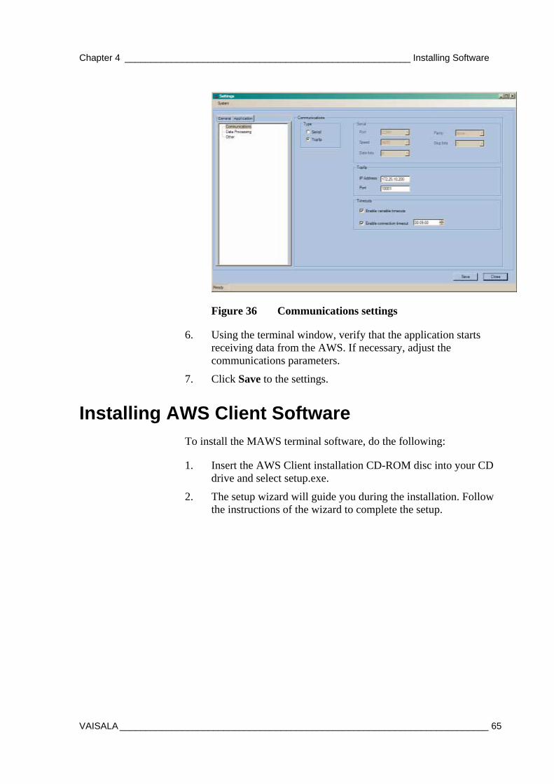
Chapter 4 _______________________________________________________ Installing Software
VAISALA _______________________________________________________________________ 65
Figure 36 Communications settings
6. Using the terminal window, verify that the application starts receiving data from the AWS. If necessary, adjust the communications parameters.
7. Click Save to the settings.
Installing AWS Client Software To install the MAWS terminal software, do the following:
1. Insert the AWS Client installation CD-ROM disc into your CD drive and select setup.exe.
2. The setup wizard will guide you during the installation. Follow the instructions of the wizard to complete the setup.

USER'S GUIDE____________________________________________________________________
66 __________________________________________________________________ M210891EN-A
This page intentionally left blank.
Chapter 5 _____________________________________________ Operating Observation Console
VAISALA _______________________________________________________________________ 67
CHAPTER 5
OPERATING OBSERVATION CONSOLE
This chapter contains information on viewing meteorological measurement data and generating meteorological messages FM-13 SHIP and IMMT-3.
Introduction to Vaisala Maritime Observation Console
Vaisala Maritime Observation Console is a PC software application for displaying and storing meteorological measurement data.
Operation Console Versions The full version of the software (AWS400VMOC) also includes editing meteorological measurement data and generating standard meteorological messages FM-13 SHIP and IMMT-3.
The light version of the software (AWS400DISP) can be used only as a real-time weather display.
USER'S GUIDE____________________________________________________________________
68 __________________________________________________________________ M210891EN-A
Starting and Exiting See sections Installing Software on page 61 and Minimum Configuration Steps on page 64.
To open the Vaisala Maritime Observation Console, do the following:
- Select Start - Programs - Vaisala - Observation Console. The Observation Console weather data display will be displayed.
To exit the Vaisala Maritime Observation Console, do the following:
- In the Observation Console weather data display, select System - Exit. The software will close and all data logging and message generation will stop.
NOTE When you select System - Exit the data logging and message generation will stop.
Weather Data Display Open the Vaisala Maritime Observation Console from the Start menu (Vaisala - Observation Console). The main user interface, the real-time weather display, is displayed, see Figure 37 on page 69.
The display consists of real-time text section on the left and graph section on the right. For details, see below.
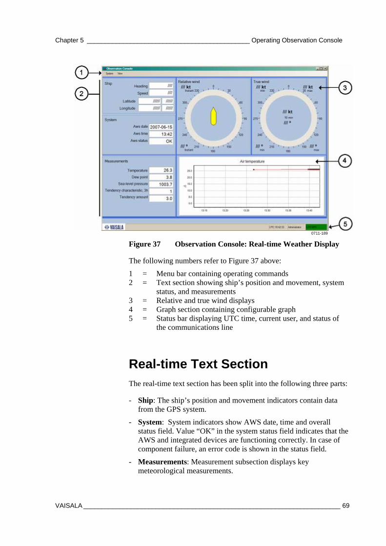
Chapter 5 _____________________________________________ Operating Observation Console
VAISALA _______________________________________________________________________ 69
0711-189
Figure 37 Observation Console: Real-time Weather Display
The following numbers refer to Figure 37 above:
1 = Menu bar containing operating commands 2 = Text section showing ship’s position and movement, system
status, and measurements 3 = Relative and true wind displays 4 = Graph section containing configurable graph 5 = Status bar displaying UTC time, current user, and status of
the communications line
Real-time Text Section The real-time text section has been split into the following three parts:
- Ship: The ship’s position and movement indicators contain data from the GPS system.
- System: System indicators show AWS date, time and overall status field. Value “OK” in the system status field indicates that the AWS and integrated devices are functioning correctly. In case of component failure, an error code is shown in the status field.
- Measurements: Measurement subsection displays key meteorological measurements.
USER'S GUIDE____________________________________________________________________
70 __________________________________________________________________ M210891EN-A
Changing Text Box Settings
All graph settings can be accessed using the right mouse button.
Some settings are available to Administrator only, typically the ones marked with * in the table below.
Table 4 Text Section Settings (Right-click Menu) Property Description
Enter text * Change the header texts manually. Variable* Select variables to display. Unit* By default, variables are shown in the unit shown in the
variable list. However, it is possible to make unit conversions on the user interface. The Unit menu item indicates the possible units into which the value can be changed. For instance, to display atmospheric pressure (QFE) in technical mercury inches, click “select unit…” and choose the last row on the dialog.
Alarm Select when and how an alarm will be issued. You can configure the user interface to issue an alarm if a value exceeds a preset limit. In the alarm configuration dialog (Settings), you can define the alarm variable, limit value, and alarm reaction: visual indication, sound, and/or log entry.
Visible Select if the item is displayed or not.
Graph Section All graph settings can be accessed using the right mouse button.
Table 5 Graph Settings (Right-click Menu) Mouse Menu Item Description Variables Select variables to display. The graph supports up
to 6 different variables. Line Width Select the size of the line that connects the
measurement points. Marker Size Select the size of the marker dot on top of each
measurement point. Y-Axis Set manually the Y-axis length. X-Axis length Set manually the X-axis length. Time Settings Allows shifting of measurement time (X-coordinate)
by a constant value. This setting can be used to display graph in local time while having AWS in UTC time. The setting only affects the graph.
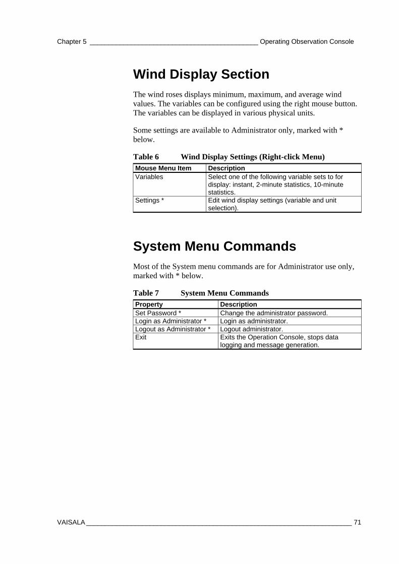
Chapter 5 _____________________________________________ Operating Observation Console
VAISALA _______________________________________________________________________ 71
Wind Display Section The wind roses displays minimum, maximum, and average wind values. The variables can be configured using the right mouse button. The variables can be displayed in various physical units.
Some settings are available to Administrator only, marked with * below.
Table 6 Wind Display Settings (Right-click Menu) Mouse Menu Item Description Variables Select one of the following variable sets to for
display: instant, 2-minute statistics, 10-minute statistics.
Settings * Edit wind display settings (variable and unit selection).
System Menu Commands Most of the System menu commands are for Administrator use only, marked with * below.
Table 7 System Menu Commands Property Description Set Password * Change the administrator password. Login as Administrator * Login as administrator. Logout as Administrator * Logout administrator. Exit Exits the Operation Console, stops data
logging and message generation.
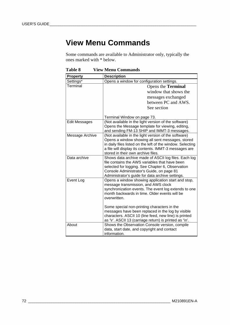
USER'S GUIDE____________________________________________________________________
72 __________________________________________________________________ M210891EN-A
View Menu Commands Some commands are available to Administrator only, typically the ones marked with * below.
Table 8 View Menu Commands Property Description Settings* Opens a window for configuration settings. Terminal Opens the Terminal
window that shows the messages exchanged between PC and AWS. See section
Terminal Window on page 73. Edit Messages (Not available in the light version of the software)
Opens the Message template for viewing, editing, and sending FM-13 SHIP and IMMT-3 messages.
Message Archive (Not available in the light version of the software) Opens a window showing all sent messages, stored in daily files listed on the left of the window. Selecting a file will display its contents. IMMT-3 messages are stored in their own archive files.
Data archive Shows data archive made of ASCII log files. Each log file contains the AWS variables that have been selected for logging. See Chapter 6, Observation Console Administrator's Guide, on page 81 Administrator’s guide for data archive settings.
Event Log Opens a window showing application start and stop, message transmission, and AWS clock synchronization events. The event log extends to one month backwards in time. Older events will be overwritten. Some special non-printing characters in the messages have been replaced in the log by visible characters. ASCII 10 (line feed, new line) is printed as ‘\r’. ASCII 13 (carriage return) is printed as ‘\n’.
About Shows the Observation Console version, compile data, start date, and copyright and contact information.
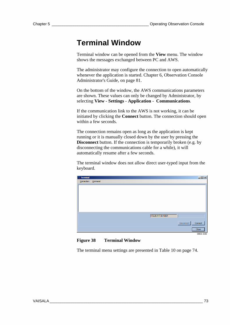
Chapter 5 _____________________________________________ Operating Observation Console
VAISALA _______________________________________________________________________ 73
Terminal Window Terminal window can be opened from the View menu. The window shows the messages exchanged between PC and AWS.
The administrator may configure the connection to open automatically whenever the application is started. Chapter 6, Observation Console Administrator's Guide, on page 81.
On the bottom of the window, the AWS communications parameters are shown. These values can only be changed by Administrator, by selecting View - Settings - Application - Communications.
If the communication link to the AWS is not working, it can be initiated by clicking the Connect button. The connection should open within a few seconds.
The connection remains open as long as the application is kept running or it is manually closed down by the user by pressing the Disconnect button. If the connection is temporarily broken (e.g. by disconnecting the communications cable for a while), it will automatically resume after a few seconds.
The terminal window does not allow direct user-typed input from the keyboard.
0801-030
Figure 38 Terminal Window
The terminal menu settings are presented in Table 10 on page 74.
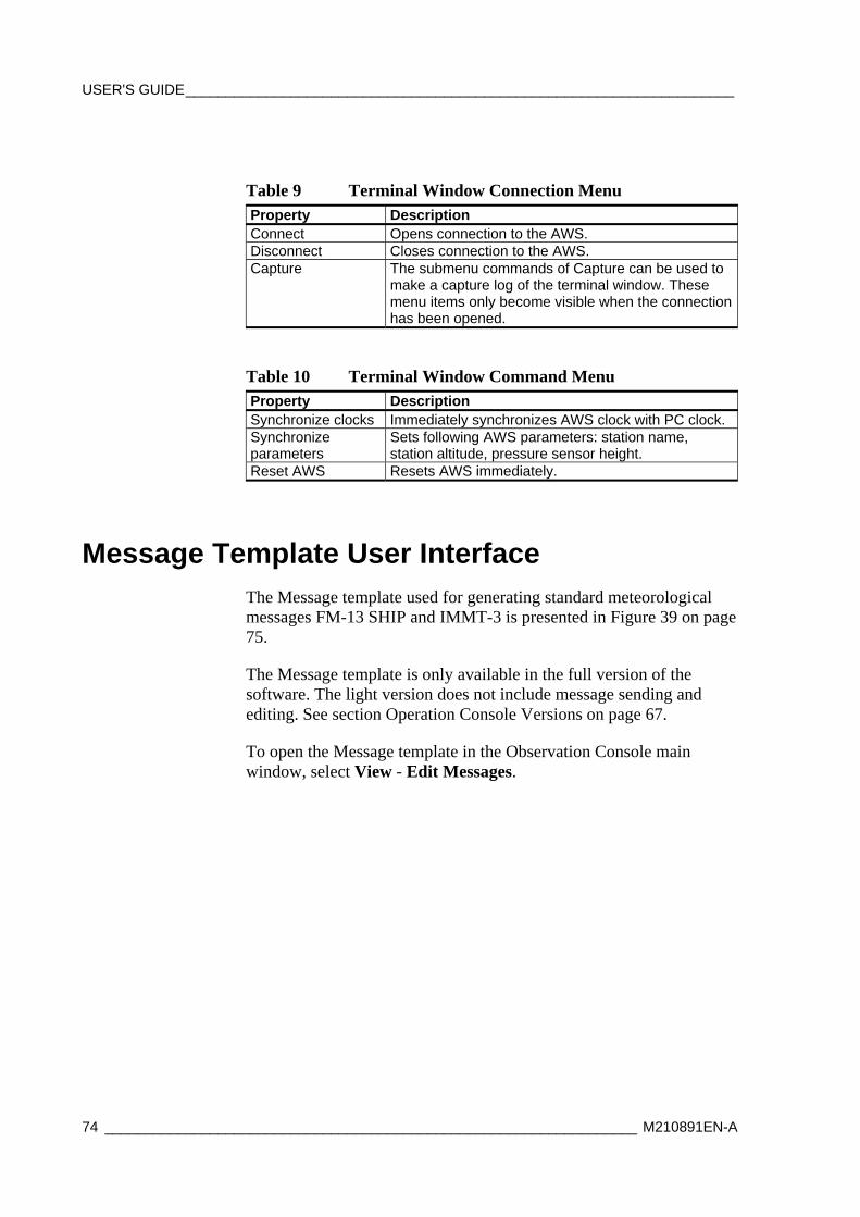
USER'S GUIDE____________________________________________________________________
74 __________________________________________________________________ M210891EN-A
Table 9 Terminal Window Connection Menu Property Description Connect Opens connection to the AWS. Disconnect Closes connection to the AWS. Capture The submenu commands of Capture can be used to
make a capture log of the terminal window. These menu items only become visible when the connection has been opened.
Table 10 Terminal Window Command Menu Property Description Synchronize clocks Immediately synchronizes AWS clock with PC clock. Synchronize parameters
Sets following AWS parameters: station name, station altitude, pressure sensor height.
Reset AWS Resets AWS immediately.
Message Template User Interface The Message template used for generating standard meteorological messages FM-13 SHIP and IMMT-3 is presented in Figure 39 on page 75.
The Message template is only available in the full version of the software. The light version does not include message sending and editing. See section Operation Console Versions on page 67.
To open the Message template in the Observation Console main window, select View - Edit Messages.
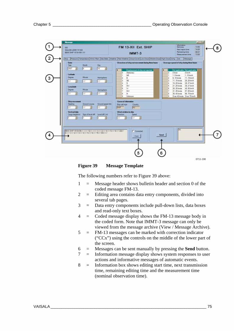
Chapter 5 _____________________________________________ Operating Observation Console
VAISALA _______________________________________________________________________ 75
0711-190
Figure 39 Message Template
The following numbers refer to Figure 39 above:
1 = Message header shows bulletin header and section 0 of the coded message FM-13.
2 = Editing area contains data entry components, divided into several tab pages.
3 = Data entry components include pull-down lists, data boxes and read-only text boxes.
4 = Coded message display shows the FM-13 message body in the coded form. Note that IMMT-3 message can only be viewed from the message archive (View / Message Archive).
5 = FM-13 messages can be marked with correction indicator (“CCx”) using the controls on the middle of the lower part of the screen.
6 = Messages can be sent manually by pressing the Send button. 7 = Information message display shows system responses to user
actions and informative messages of automatic events. 8 = Information box shows editing start time, next transmission
time, remaining editing time and the measurement time (nominal observation time).
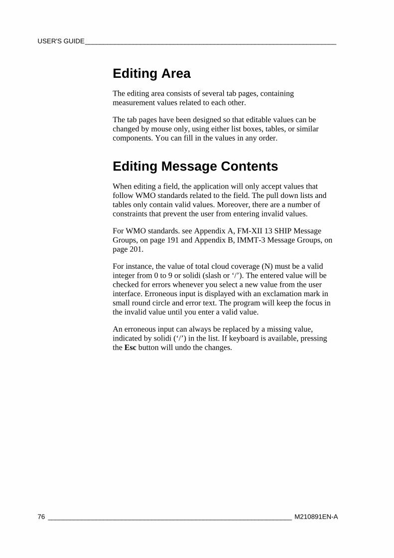
USER'S GUIDE____________________________________________________________________
76 __________________________________________________________________ M210891EN-A
Editing Area The editing area consists of several tab pages, containing measurement values related to each other.
The tab pages have been designed so that editable values can be changed by mouse only, using either list boxes, tables, or similar components. You can fill in the values in any order.
Editing Message Contents When editing a field, the application will only accept values that follow WMO standards related to the field. The pull down lists and tables only contain valid values. Moreover, there are a number of constraints that prevent the user from entering invalid values.
For WMO standards. see Appendix A, FM-XII 13 SHIP Message Groups, on page 191 and Appendix B, IMMT-3 Message Groups, on page 201.
For instance, the value of total cloud coverage (N) must be a valid integer from 0 to 9 or solidi (slash or ‘/’). The entered value will be checked for errors whenever you select a new value from the user interface. Erroneous input is displayed with an exclamation mark in small round circle and error text. The program will keep the focus in the invalid value until you enter a valid value.
An erroneous input can always be replaced by a missing value, indicated by solidi (‘/’) in the list. If keyboard is available, pressing the Esc button will undo the changes.
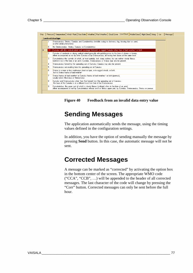
Chapter 5 _____________________________________________ Operating Observation Console
VAISALA _______________________________________________________________________ 77
Figure 40 Feedback from an invalid data entry value
Sending Messages The application automatically sends the message, using the timing values defined in the configuration settings.
In addition, you have the option of sending manually the message by pressing Send button. In this case, the automatic message will not be sent.
Corrected Messages A message can be marked as “corrected” by activating the option box in the bottom center of the screen. The appropriate WMO code (“CCA”, “CCB”, …) will be appended to the header of all corrected messages. The last character of the code will change by pressing the “Corr” button. Corrected messages can only be sent before the full hour.
USER'S GUIDE____________________________________________________________________
78 __________________________________________________________________ M210891EN-A
Automatic Functionalities The Observation Console contains the following automatic functionalities:
Automatic Connection
The application can be configured to open connection to AWS automatically.
Real-time Display
All AWS data is displayed on the real-time display.
AWS Clock Synchronization
Once per day, the application synchronizes AWS clock using the PC clock as reference.
Data Logging
Aws data will be stored in ASCII files according to administrator’s settings.
Message Logging
All generated messages will be stored in ASCII files. This functionality is not available in the light version of the software. Note that the messages may be forwarded to an external location (other PC or data logger).
Event Logging
All key events will be stored in a history log.
Automatic Screenshots
If automatic screenshots are enabled, the application stores a screenshot of the main window in .jpg format. The file can be used by external applications that need to access the real-time display data.
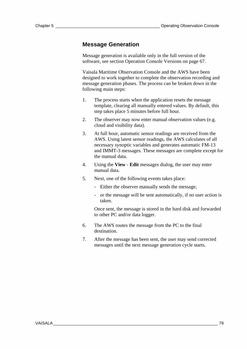
Chapter 5 _____________________________________________ Operating Observation Console
VAISALA _______________________________________________________________________ 79
Message Generation
Message generation is available only in the full version of the software, see section Operation Console Versions on page 67.
Vaisala Maritime Observation Console and the AWS have been designed to work together to complete the observation recording and message generation phases. The process can be broken down in the following main steps:
1. The process starts when the application resets the message template, clearing all manually entered values. By default, this step takes place 5 minutes before full hour.
2. The observer may now enter manual observation values (e.g. cloud and visibility data).
3. At full hour, automatic sensor readings are received from the AWS. Using latest sensor readings, the AWS calculates of all necessary synoptic variables and generates automatic FM-13 and IMMT-3 messages. These messages are complete except for the manual data.
4. Using the View - Edit messages dialog, the user may enter manual data.
5. Next, one of the following events takes place:
- Either the observer manually sends the message,
- or the message will be sent automatically, if no user action is taken.
Once sent, the message is stored in the hard disk and forwarded to other PC and/or data logger.
6. The AWS routes the message from the PC to the final destination.
7. After the message has been sent, the user may send corrected messages until the next message generation cycle starts.
USER'S GUIDE____________________________________________________________________
80 __________________________________________________________________ M210891EN-A
0801-031
Figure 41 Timing Diagram
If the user does not make any changes to the message, the application returns a message identical to the one generated by the AWS.
If the Observation Console application is closed or the PC malfunctions, the AWS will send the automatically generated message (step 1).
Chapter 6 ____________________________________ Observation Console Administrator's Guide
VAISALA _______________________________________________________________________ 81
CHAPTER 6
OBSERVATION CONSOLE ADMINISTRATOR'S GUIDE
This chapter provides you with information on configuring all settings in the software.
User Accounts
General Vaisala Observation Console supports two separate user accounts:
- When the user is logged in as administrator, he can change all configuration settings and use all functions in the application.
- When the user is logged in as observer, the configuration settings cannot be modified.
Normally, users log in as observers, as the configuration settings need not be modified after initial installation. The administrator’s account is protected by password.
Logging in as Administrator When the application is started, the user is automatically given the observer role. To log on as administrator, do the following:
1. Select Login as administrator from the System menu.
2. Enter the password in the dialog that opens.
USER'S GUIDE____________________________________________________________________
82 __________________________________________________________________ M210891EN-A
NOTE After initial setup, administrator’s password is empty.
3. Once the password has been verified, the configuration dialog (View - Settings) can be accessed.
Changing Administrator’s Password Only administrator can alter the password:
1. From the System menu, select Set Password.
2. Enter the new password, confirm, and click OK.
NOTE If you forget the password, the application has to be reinstalled to regain access as administrator.
Logging in as Observer The observer account is activated by default at startup. To switch back from administrator into observer account without restarting the application, select Logout as Administrator from the System menu.
General Definitions The following definitions will be helpful in configuring the application:
AWS Variable
An "AWS variable" refers to an input value from the AWS. The message sent by the AWS contains a number of AWS variables, which will be processed by in the console. Note that the AWS variables may not be direct sensor readings. Instead, they have been processed by the data logger application.
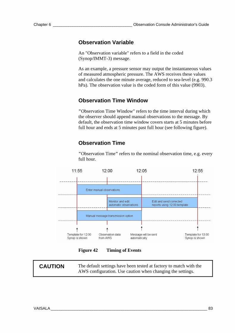
Chapter 6 ____________________________________ Observation Console Administrator's Guide
VAISALA _______________________________________________________________________ 83
Observation Variable
An "Observation variable" refers to a field in the coded (Synop/IMMT-3) message.
As an example, a pressure sensor may output the instantaneous values of measured atmospheric pressure. The AWS receives these values and calculates the one minute average, reduced to sea-level (e.g. 990.3 hPa). The observation value is the coded form of this value (9903).
Observation Time Window
"Observation Time Window" refers to the time interval during which the observer should append manual observations to the message. By default, the observation time window covers starts at 5 minutes before full hour and ends at 5 minutes past full hour (see following figure).
Observation Time
"Observation Time" refers to the nominal observation time, e.g. every full hour.
Figure 42 Timing of Events
CAUTION The default settings have been tested at factory to match with the AWS configuration. Use caution when changing the settings.
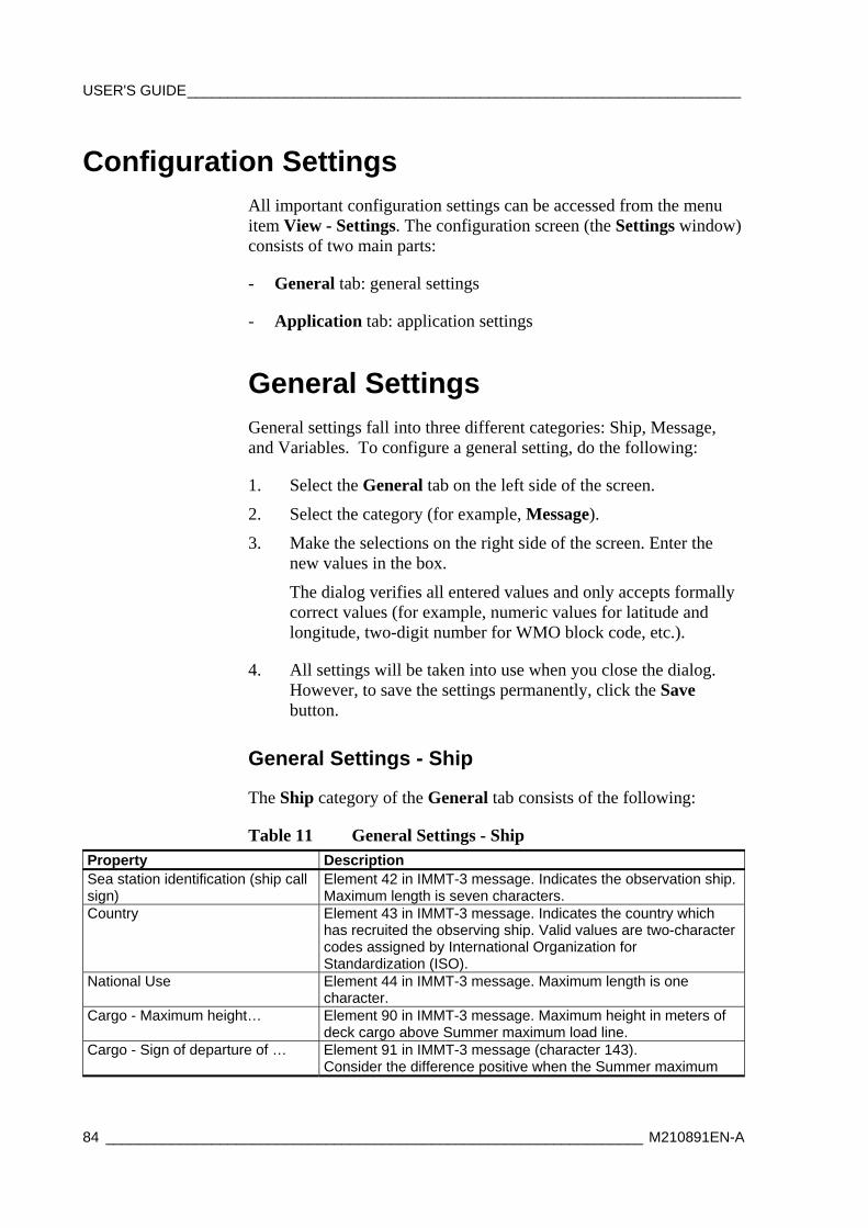
USER'S GUIDE____________________________________________________________________
84 __________________________________________________________________ M210891EN-A
Configuration Settings All important configuration settings can be accessed from the menu item View - Settings. The configuration screen (the Settings window) consists of two main parts:
- General tab: general settings
- Application tab: application settings
General Settings General settings fall into three different categories: Ship, Message, and Variables. To configure a general setting, do the following:
1. Select the General tab on the left side of the screen.
2. Select the category (for example, Message).
3. Make the selections on the right side of the screen. Enter the new values in the box.
The dialog verifies all entered values and only accepts formally correct values (for example, numeric values for latitude and longitude, two-digit number for WMO block code, etc.).
4. All settings will be taken into use when you close the dialog. However, to save the settings permanently, click the Save button.
General Settings - Ship
The Ship category of the General tab consists of the following:
Table 11 General Settings - Ship Property Description Sea station identification (ship call sign)
Element 42 in IMMT-3 message. Indicates the observation ship. Maximum length is seven characters.
Country Element 43 in IMMT-3 message. Indicates the country which has recruited the observing ship. Valid values are two-character codes assigned by International Organization for Standardization (ISO).
National Use Element 44 in IMMT-3 message. Maximum length is one character.
Cargo - Maximum height… Element 90 in IMMT-3 message. Maximum height in meters of deck cargo above Summer maximum load line.
Cargo - Sign of departure of … Element 91 in IMMT-3 message (character 143). Consider the difference positive when the Summer maximum
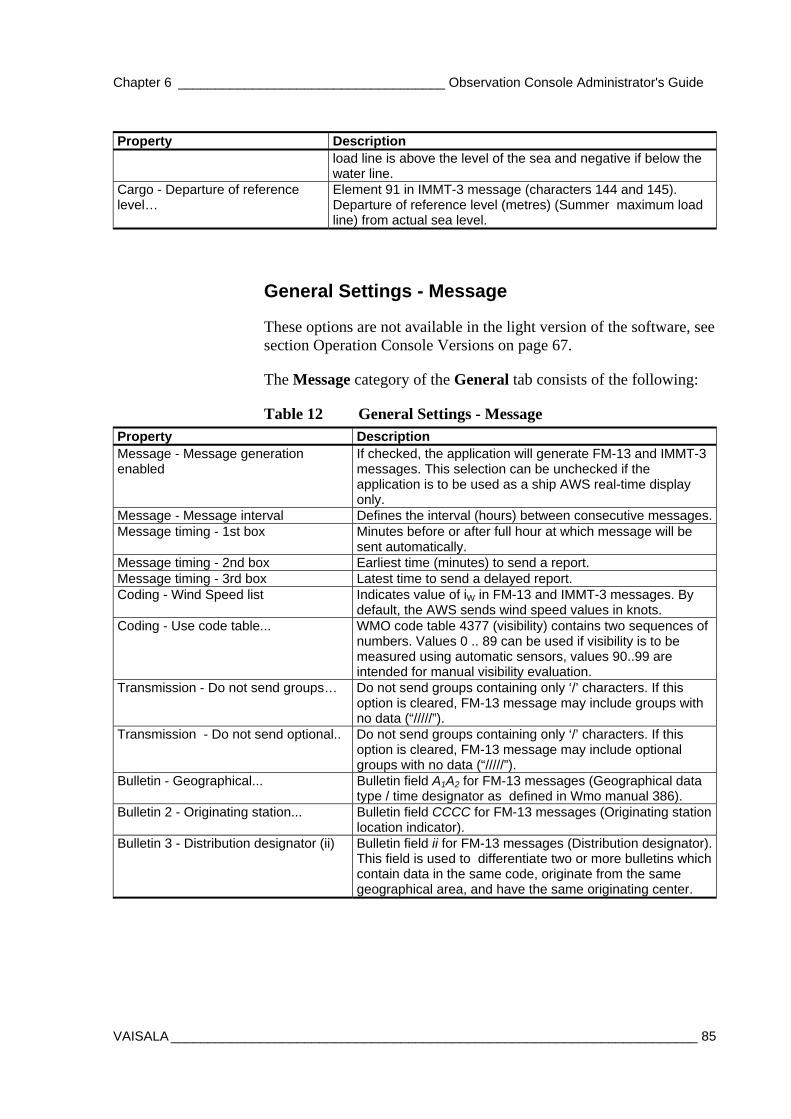
Chapter 6 ____________________________________ Observation Console Administrator's Guide
VAISALA _______________________________________________________________________ 85
Property Description load line is above the level of the sea and negative if below the water line.
Cargo - Departure of reference level…
Element 91 in IMMT-3 message (characters 144 and 145). Departure of reference level (metres) (Summer maximum load line) from actual sea level.
General Settings - Message
These options are not available in the light version of the software, see section Operation Console Versions on page 67.
The Message category of the General tab consists of the following:
Table 12 General Settings - Message Property Description Message - Message generation enabled
If checked, the application will generate FM-13 and IMMT-3 messages. This selection can be unchecked if the application is to be used as a ship AWS real-time display only.
Message - Message interval Defines the interval (hours) between consecutive messages. Message timing - 1st box Minutes before or after full hour at which message will be
sent automatically. Message timing - 2nd box Earliest time (minutes) to send a report. Message timing - 3rd box Latest time to send a delayed report. Coding - Wind Speed list Indicates value of iW in FM-13 and IMMT-3 messages. By
default, the AWS sends wind speed values in knots. Coding - Use code table... WMO code table 4377 (visibility) contains two sequences of
numbers. Values 0 .. 89 can be used if visibility is to be measured using automatic sensors, values 90..99 are intended for manual visibility evaluation.
Transmission - Do not send groups… Do not send groups containing only ‘/’ characters. If this option is cleared, FM-13 message may include groups with no data (“/////”).
Transmission - Do not send optional.. Do not send groups containing only ‘/’ characters. If this option is cleared, FM-13 message may include optional groups with no data (“/////”).
Bulletin - Geographical... Bulletin field A1A2 for FM-13 messages (Geographical data type / time designator as defined in Wmo manual 386).
Bulletin 2 - Originating station... Bulletin field CCCC for FM-13 messages (Originating station location indicator).
Bulletin 3 - Distribution designator (ii) Bulletin field ii for FM-13 messages (Distribution designator). This field is used to differentiate two or more bulletins which contain data in the same code, originate from the same geographical area, and have the same originating center.
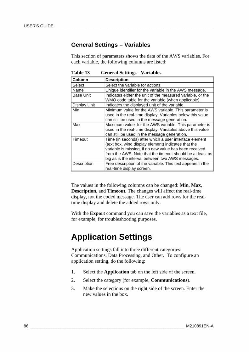
USER'S GUIDE____________________________________________________________________
86 __________________________________________________________________ M210891EN-A
General Settings – Variables
This section of parameters shows the data of the AWS variables. For each variable, the following columns are listed:
Table 13 General Settings - Variables Column Description Select Select the variable for actions. Name Unique identifier for the variable in the AWS message. Base Unit Indicates either the unit of the measured variable, or the
WMO code table for the variable (when applicable). Display Unit Indicates the displayed unit of the variable. Min Minimum value for the AWS variable. This parameter is
used in the real-time display. Variables below this value can still be used in the message generation.
Max Maximum value for the AWS variable. This parameter is used in the real-time display. Variables above this value can still be used in the message generation.
Timeout Time (in seconds) after which a user interface element (text box, wind display element) indicates that the variable is missing, if no new value has been received from the AWS. Note that the timeout should be at least as big as is the interval between two AWS messages.
Description Free description of the variable. This text appears in the real-time display screen.
The values in the following columns can be changed: Min, Max, Description, and Timeout. The changes will affect the real-time display, not the coded message. The user can add rows for the real-time display and delete the added rows only.
With the Export command you can save the variables as a text file, for example, for troubleshooting purposes.
Application Settings Application settings fall into three different categories: Communications, Data Processing, and Other. To configure an application setting, do the following:
1. Select the Application tab on the left side of the screen.
2. Select the category (for example, Communications).
3. Make the selections on the right side of the screen. Enter the new values in the box.
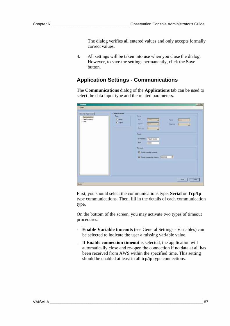
Chapter 6 ____________________________________ Observation Console Administrator's Guide
VAISALA _______________________________________________________________________ 87
The dialog verifies all entered values and only accepts formally correct values.
4. All settings will be taken into use when you close the dialog. However, to save the settings permanently, click the Save button.
Application Settings - Communications
The Communications dialog of the Applications tab can be used to select the data input type and the related parameters.
First, you should select the communications type: Serial or Tcp/Ip type communications. Then, fill in the details of each communication type.
On the bottom of the screen, you may activate two types of timeout procedures:
- Enable Variable timeouts (see General Settings - Variables) can be selected to indicate the user a missing variable value.
- If Enable connection timeout is selected, the application will automatically close and re-open the connection if no data at all has been received from AWS within the specified time. This setting should be enabled at least in all tcp/ip type connections.
USER'S GUIDE____________________________________________________________________
88 __________________________________________________________________ M210891EN-A
Application Settings – Data Processing
The Data Processing category of the Application Settings contains the following:
Log Groups can be utilized to store received data in ASCII files. A log group may contain one or more AWS variables. The received variables will be automatically saved into log files, under the \log subdirectory. Each group has its own set of files. The application supports up to five different log groups.
As the AWS may be transmitting variables at different intervals (e.g. wind message at 3 second intervals and general message at 1 minute interval), it is recommended that each log group only contains variables that are received in the same message.
To configure log groups, do the following:
1. First check the Enabled check box.
2. Next, add variables into a group by clicking Select in the group table. From the dialog that opens, select the variables.
The log files will be named using the log group identifier and date/time when the configuration settings were made.
The Interval setting defines how often variables are logged. By default, every time a new variable is received, it will be stored in the file. Choosing another interval makes the application only to store the variables after the specified time. The interval setting uses 00:00 h as its synchronization time. For instance, using 6 h interval would store data from the first messages received after 00:00, 06:00, 12:00 and 18:00. The Span of log file setting indicates how often a new log file will be started.
If the Message forwarding setting is enabled, all coded messages will be transferred immediately to a given location. This setting allows external software to use the messages as input source.
If the Latest Data Files setting is enabled, the latest data files will be automatically copied to the given location.
Chapter 6 ____________________________________ Observation Console Administrator's Guide
VAISALA _______________________________________________________________________ 89
Application Settings – Other
This dialog contains miscellaneous settings.
If Time synchronization is enabled, the application synchronizes AWS clock with the PC clock at the given time, once per day.
Start-up actions can be used to reduce manual work when launching the application. Selecting Log in as administrator automatically gives all users possibility to change settings. If Open connection automatically is selected, the user does not need to use terminal dialog to start receiving data.
If enabled, Automatic screenshot function will save an image of the main window into a .jpg file at regular intervals. This functionality has been included to offer simple method of distributing images of real-time data to other users.
By default, the file is named screenshot.jpg. The user can define the destination directory and screenshot interval.
System Menu The System menu is in the Settings window and contains the following:
Observations - Configuration Report To see a summary of the AWS variables used as input to message variables, select Observations from the System menu. The Configuration Report window is displayed.
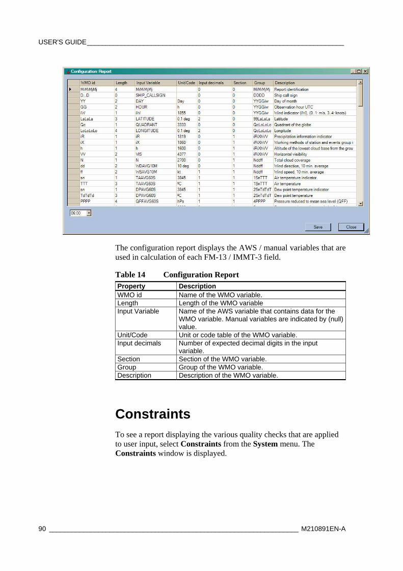
USER'S GUIDE____________________________________________________________________
90 __________________________________________________________________ M210891EN-A
The configuration report displays the AWS / manual variables that are used in calculation of each FM-13 / IMMT-3 field.
Table 14 Configuration Report Property Description WMO id Name of the WMO variable. Length Length of the WMO variable Input Variable Name of the AWS variable that contains data for the
WMO variable. Manual variables are indicated by (null) value.
Unit/Code Unit or code table of the WMO variable. Input decimals Number of expected decimal digits in the input
variable. Section Section of the WMO variable. Group Group of the WMO variable. Description Description of the WMO variable.
Constraints To see a report displaying the various quality checks that are applied to user input, select Constraints from the System menu. The Constraints window is displayed.
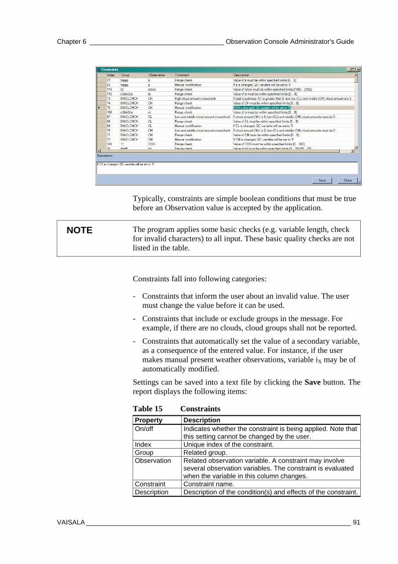
Chapter 6 ____________________________________ Observation Console Administrator's Guide
VAISALA _______________________________________________________________________ 91
Typically, constraints are simple boolean conditions that must be true before an Observation value is accepted by the application.
NOTE The program applies some basic checks (e.g. variable length, check for invalid characters) to all input. These basic quality checks are not listed in the table.
Constraints fall into following categories:
- Constraints that inform the user about an invalid value. The user must change the value before it can be used.
- Constraints that include or exclude groups in the message. For example, if there are no clouds, cloud groups shall not be reported.
- Constraints that automatically set the value of a secondary variable, as a consequence of the entered value. For instance, if the user makes manual present weather observations, variable iX may be of automatically modified.
Settings can be saved into a text file by clicking the Save button. The report displays the following items:
Table 15 Constraints Property Description On/off Indicates whether the constraint is being applied. Note that
this setting cannot be changed by the user. Index Unique index of the constraint. Group Related group. Observation Related observation variable. A constraint may involve
several observation variables. The constraint is evaluated when the variable in this column changes.
Constraint Constraint name. Description Description of the condition(s) and effects of the constraint.

USER'S GUIDE____________________________________________________________________
92 __________________________________________________________________ M210891EN-A
This page intentionally left blank.
Chapter 7 ____________________________________________________ Operating AWS Client
VAISALA _______________________________________________________________________ 93
CHAPTER 7
OPERATING AWS CLIENT
This chapter provides information on using the AWS Client software. It is used for downloading data log files to a PC, and for viewing the files.
Vaisala HydroMet™ Automatic Weather Station Client, or AWS Client for short, is used for setting station-specific parameters such as the station name, altitude, pressure sensor height, and sensor-specific calibration coefficients. In addition, the date and time can be set with the easy-to-use Station Settings template.
You can browse the data files by downloading them from the logger to your PC. You can browse them in the AWS Client software or in other applications. You can define several download settings such as where you want to save the downloaded files and what operations the program performs automatically at each download.
Installing AWS Client To install the MAWS terminal software, do the following:
1. Insert the AWS Client installation CD-ROM disc into your CD drive and select setup.exe.
2. The setup wizard will guide you during the installation. Follow the instructions of the wizard to complete the setup.
Establishing Terminal Connection To connect your computer to a the QML logger serial port, proceed as follows:
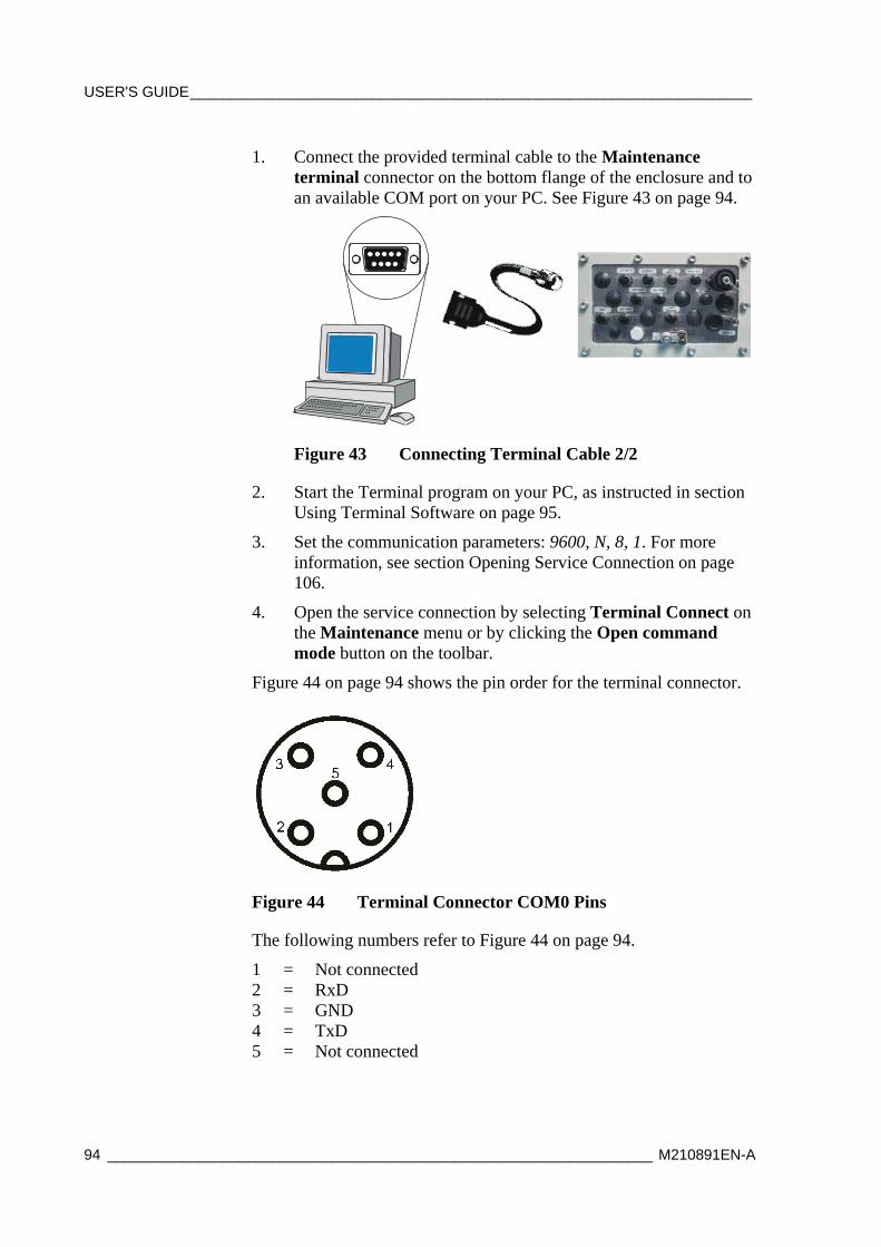
USER'S GUIDE____________________________________________________________________
94 __________________________________________________________________ M210891EN-A
1. Connect the provided terminal cable to the Maintenance terminal connector on the bottom flange of the enclosure and to an available COM port on your PC. See Figure 43 on page 94.
Figure 43 Connecting Terminal Cable 2/2
2. Start the Terminal program on your PC, as instructed in section Using Terminal Software on page 95.
3. Set the communication parameters: 9600, N, 8, 1. For more information, see section Opening Service Connection on page 106.
4. Open the service connection by selecting Terminal Connect on the Maintenance menu or by clicking the Open command mode button on the toolbar.
Figure 44 on page 94 shows the pin order for the terminal connector.
Figure 44 Terminal Connector COM0 Pins
The following numbers refer to Figure 44 on page 94.
1 = Not connected 2 = RxD 3 = GND 4 = TxD 5 = Not connected
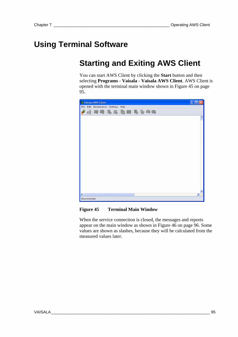
Chapter 7 ____________________________________________________ Operating AWS Client
VAISALA _______________________________________________________________________ 95
Using Terminal Software
Starting and Exiting AWS Client You can start AWS Client by clicking the Start button and then selecting Programs - Vaisala - Vaisala AWS Client. AWS Client is opened with the terminal main window shown in Figure 45 on page 95.
Figure 45 Terminal Main Window
When the service connection is closed, the messages and reports appear on the main window as shown in Figure 46 on page 96. Some values are shown as slashes, because they will be calculated from the measured values later.

USER'S GUIDE____________________________________________________________________
96 __________________________________________________________________ M210891EN-A
Figure 46 Terminal Showing Report
NOTE The report type and appearance shown in Figure 46 on page 96 depend on your setup.
You can exit AWS Client by selecting the Exit option from the File menu.
AWS Client Main Window On top of the main window you can find the AWS Client toolbar. The toolbar is the quickest way to select functions.
Table 16 Toolbar Icons and Functions Icon Function Description
Open connection Opens the address book for selecting the weather station to connect to.
Close current connection
Closes the connection to the QML logger.
Open command mode
Opens the service connection for issuing commands to the QML logger.
Close command mode
Closes the service connection. The terminal window begins to show the messages and reports configured in the QML logger.
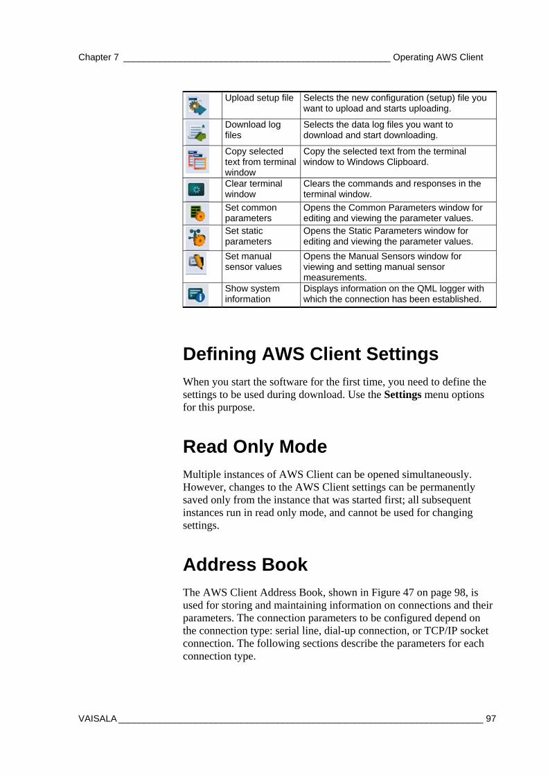
Chapter 7 ____________________________________________________ Operating AWS Client
VAISALA _______________________________________________________________________ 97
Upload setup file Selects the new configuration (setup) file you want to upload and starts uploading.
Download log files
Selects the data log files you want to download and start downloading.
Copy selected text from terminal window
Copy the selected text from the terminal window to Windows Clipboard.
Clear terminal window
Clears the commands and responses in the terminal window.
Set common parameters
Opens the Common Parameters window for editing and viewing the parameter values.
Set static parameters
Opens the Static Parameters window for editing and viewing the parameter values.
Set manual sensor values
Opens the Manual Sensors window for viewing and setting manual sensor measurements.
Show system information
Displays information on the QML logger with which the connection has been established.
Defining AWS Client Settings When you start the software for the first time, you need to define the settings to be used during download. Use the Settings menu options for this purpose.
Read Only Mode Multiple instances of AWS Client can be opened simultaneously. However, changes to the AWS Client settings can be permanently saved only from the instance that was started first; all subsequent instances run in read only mode, and cannot be used for changing settings.
Address Book The AWS Client Address Book, shown in Figure 47 on page 98, is used for storing and maintaining information on connections and their parameters. The connection parameters to be configured depend on the connection type: serial line, dial-up connection, or TCP/IP socket connection. The following sections describe the parameters for each connection type.
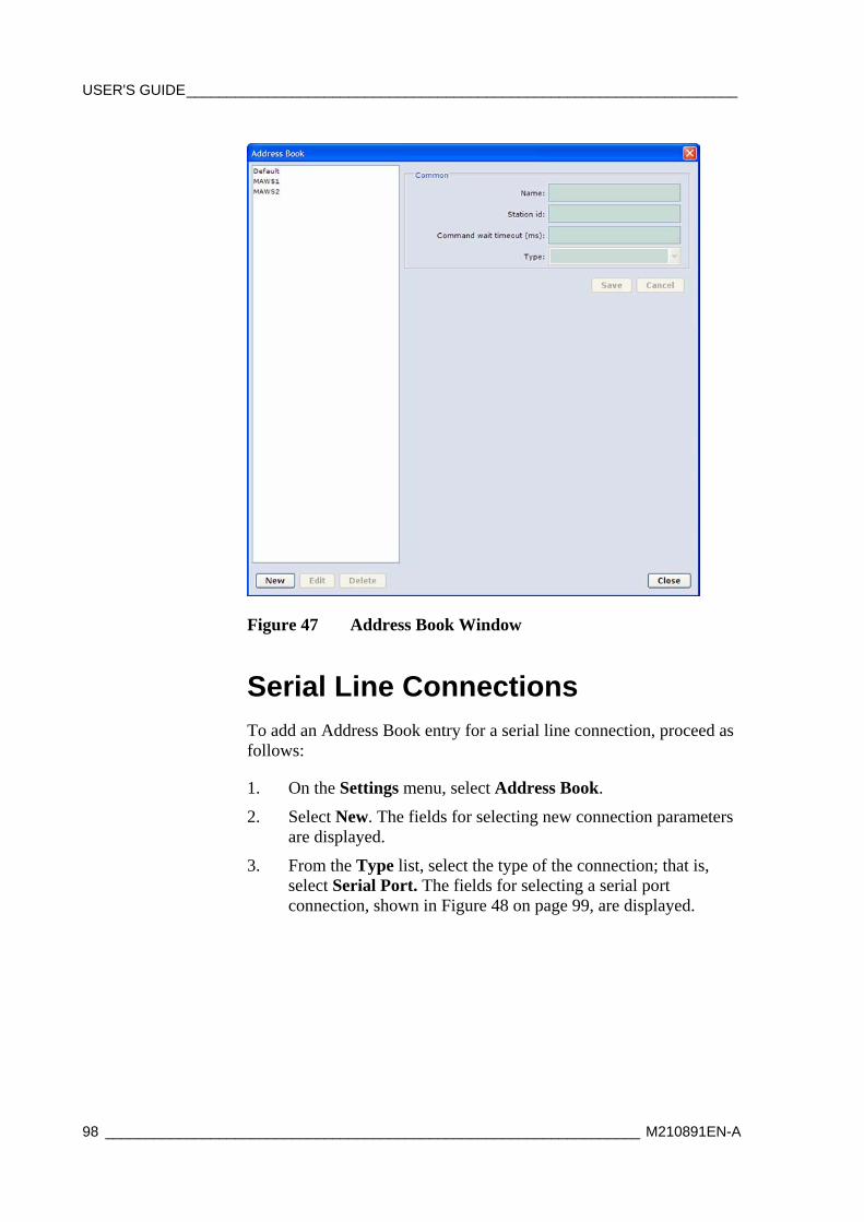
USER'S GUIDE____________________________________________________________________
98 __________________________________________________________________ M210891EN-A
Figure 47 Address Book Window
Serial Line Connections To add an Address Book entry for a serial line connection, proceed as follows:
1. On the Settings menu, select Address Book.
2. Select New. The fields for selecting new connection parameters are displayed.
3. From the Type list, select the type of the connection; that is, select Serial Port. The fields for selecting a serial port connection, shown in Figure 48 on page 99, are displayed.
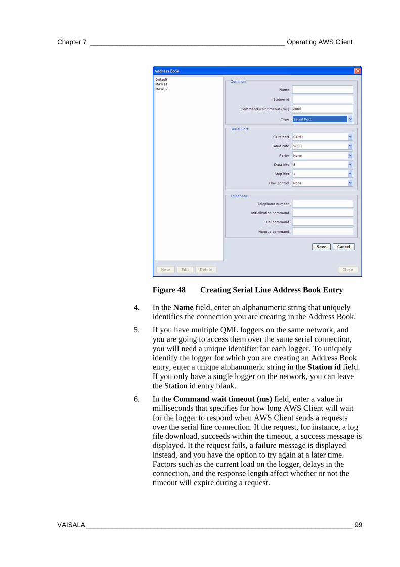
Chapter 7 ____________________________________________________ Operating AWS Client
VAISALA _______________________________________________________________________ 99
Figure 48 Creating Serial Line Address Book Entry
4. In the Name field, enter an alphanumeric string that uniquely identifies the connection you are creating in the Address Book.
5. If you have multiple QML loggers on the same network, and you are going to access them over the same serial connection, you will need a unique identifier for each logger. To uniquely identify the logger for which you are creating an Address Book entry, enter a unique alphanumeric string in the Station id field. If you only have a single logger on the network, you can leave the Station id entry blank.
6. In the Command wait timeout (ms) field, enter a value in milliseconds that specifies for how long AWS Client will wait for the logger to respond when AWS Client sends a requests over the serial line connection. If the request, for instance, a log file download, succeeds within the timeout, a success message is displayed. It the request fails, a failure message is displayed instead, and you have the option to try again at a later time. Factors such as the current load on the logger, delays in the connection, and the response length affect whether or not the timeout will expire during a request.
USER'S GUIDE____________________________________________________________________
100 _________________________________________________________________ M210891EN-A
7. From the COM port field, select the serial port to be used on your computer and the line parameters. The default line parameters for the QML logger are 9600 bps, No parity bit, 8 data bits, 1 stop bit, No flow control.
8. If you are using a modem to connect to the QML logger, enter also the Telephone number to dial, the modem Initialization and Dial commands, and the Hangup command. For instance, in the Initialization command field you could enter "ATE\rATX1"; that is, multiple AT commands separated by a "\r". Likewise, in the Dial-up command field, you could enter ATDT123456; that is, an AT command immediately followed by a phone number.
9. Save your settings and return to the Address Book window by selecting Save.
TCP/IP Socket Connections To add an Address Book entry for a TCP/IP socket connection, proceed as follows:
1. On the Settings menu, select Address Book.
2. Select New. The fields for selecting new connection parameters are displayed.
3. From the Type list, select Socket as the connection type. The fields for selecting the TCP/IP connection parameters, shown in Figure 49 on page 101, are displayed.
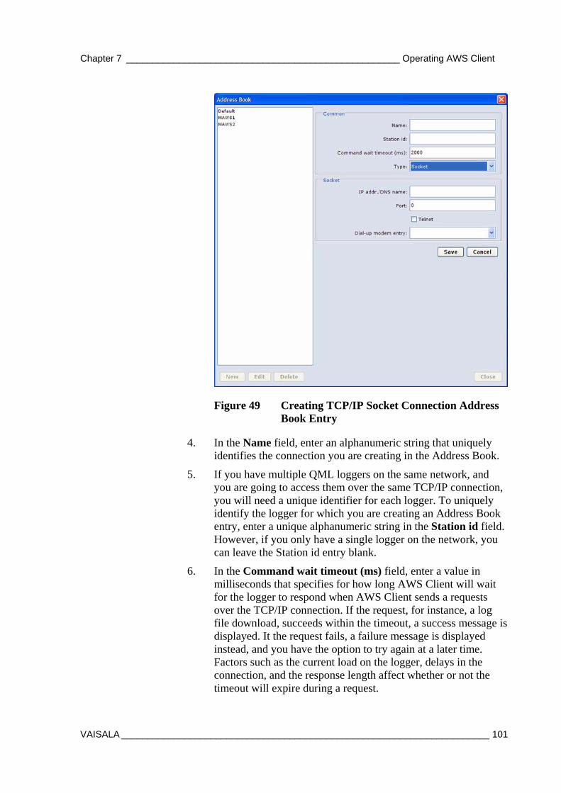
Chapter 7 ____________________________________________________ Operating AWS Client
VAISALA ______________________________________________________________________ 101
Figure 49 Creating TCP/IP Socket Connection Address Book Entry
4. In the Name field, enter an alphanumeric string that uniquely identifies the connection you are creating in the Address Book.
5. If you have multiple QML loggers on the same network, and you are going to access them over the same TCP/IP connection, you will need a unique identifier for each logger. To uniquely identify the logger for which you are creating an Address Book entry, enter a unique alphanumeric string in the Station id field. However, if you only have a single logger on the network, you can leave the Station id entry blank.
6. In the Command wait timeout (ms) field, enter a value in milliseconds that specifies for how long AWS Client will wait for the logger to respond when AWS Client sends a requests over the TCP/IP connection. If the request, for instance, a log file download, succeeds within the timeout, a success message is displayed. It the request fails, a failure message is displayed instead, and you have the option to try again at a later time. Factors such as the current load on the logger, delays in the connection, and the response length affect whether or not the timeout will expire during a request.
USER'S GUIDE____________________________________________________________________
102 _________________________________________________________________ M210891EN-A
7. In the IP addr./DNS name field, enter the destination IP address or DNS name in the IP address./DNS name field.
NOTE In order to use the DNS name, must have access to a DNS server able to resolve the DNS name to the IP address of the destination host.
8. Enter the port to be used in the Port field. Note that this must match the port set for incoming connections in the interface configuration in the QML logger.
9. If support for Telnet escape sequences for binary file transfer are required, select the Telnet option.
10. Save your settings and return to the Address Book window by selecting Save.
Dial-Up Connections The dial-up connections are based on Windows Dial-Up Networking entries, so you first need to create the connection in Windows. For information on creating Windows Dial-Up Networking connections, please see the Windows on-line help. To add an Address Book entry for the dial-up connection, proceed as follows:
1. On the Settings menu, select Address Book.
2. Select New. The fields for selecting new connection parameters are displayed.
3. From the Type list, first select Socket. The field for selecting Windows Dial-Up Networking entries is available in the window that is displayed as shown in Figure 50 on page 103.
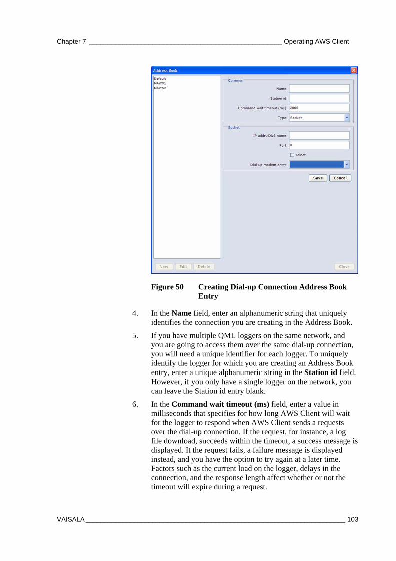
Chapter 7 ____________________________________________________ Operating AWS Client
VAISALA ______________________________________________________________________ 103
Figure 50 Creating Dial-up Connection Address Book Entry
4. In the Name field, enter an alphanumeric string that uniquely identifies the connection you are creating in the Address Book.
5. If you have multiple QML loggers on the same network, and you are going to access them over the same dial-up connection, you will need a unique identifier for each logger. To uniquely identify the logger for which you are creating an Address Book entry, enter a unique alphanumeric string in the Station id field. However, if you only have a single logger on the network, you can leave the Station id entry blank.
6. In the Command wait timeout (ms) field, enter a value in milliseconds that specifies for how long AWS Client will wait for the logger to respond when AWS Client sends a requests over the dial-up connection. If the request, for instance, a log file download, succeeds within the timeout, a success message is displayed. It the request fails, a failure message is displayed instead, and you have the option to try again at a later time. Factors such as the current load on the logger, delays in the connection, and the response length affect whether or not the timeout will expire during a request.
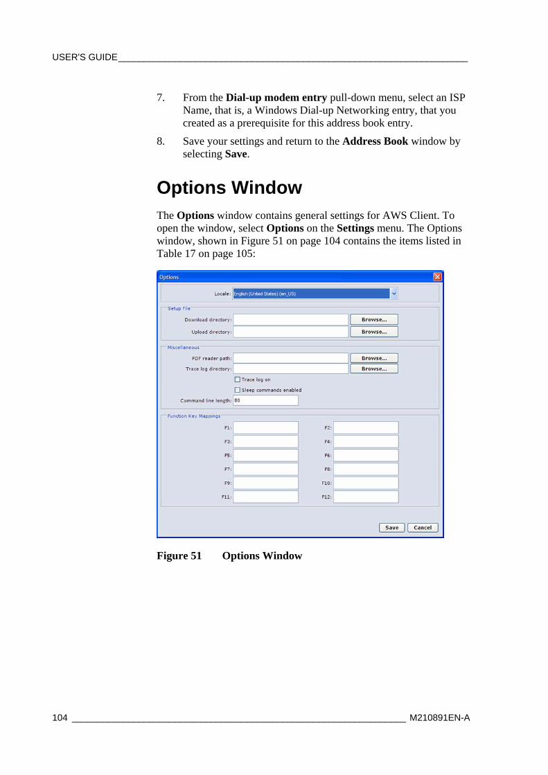
USER'S GUIDE____________________________________________________________________
104 _________________________________________________________________ M210891EN-A
7. From the Dial-up modem entry pull-down menu, select an ISP Name, that is, a Windows Dial-up Networking entry, that you created as a prerequisite for this address book entry.
8. Save your settings and return to the Address Book window by selecting Save.
Options Window The Options window contains general settings for AWS Client. To open the window, select Options on the Settings menu. The Options window, shown in Figure 51 on page 104 contains the items listed in Table 17 on page 105:
Figure 51 Options Window
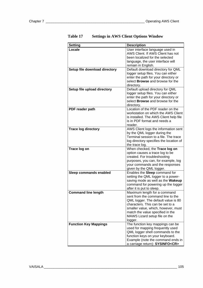
Chapter 7 ____________________________________________________ Operating AWS Client
VAISALA ______________________________________________________________________ 105
Table 17 Settings in AWS Client Options Window
Setting Description Locale User interface language used in
AWS Client. If AWS Client has not been localized for the selected language, the user interface will remain in English.
Setup file download directory Default download directory for QML logger setup files. You can either enter the path for your directory or select Browse and browse for the directory.
Setup file upload directory Default upload directory for QML logger setup files. You can either enter the path for your directory or select Browse and browse for the directory.
PDF reader path Location of the PDF reader on the workstation on which the AWS Client is installed. The AWS Client help file is in PDF format and needs a reader.
Trace log directory AWS Client logs the information sent by the QML logger during the Terminal session to a file. The trace log directory specifies the location of the trace log.
Trace log on When checked, the Trace log on option causes a trace log to be created. For troubleshooting purposes, you can, for example, log your commands and the responses given by the QML logger.
Sleep commands enabled Enables the Sleep command for setting the QML logger to a power-saving mode as well as the Wakeup command for powering up the logger after it is put to sleep.
Command line length Maximum length for a command sent from the command line to the QML logger. The default value is 80 characters. This can be set to a smaller value, which, however, must match the value specified in the MAWS Lizard setup file on the logger.
Function Key Mappings The function key mappings can be used for mapping frequently used QML logger shell commands to the function keys on your keyboard. Example (note the command ends in a carriage return): SYSINFO<CR>
USER'S GUIDE____________________________________________________________________
106 _________________________________________________________________ M210891EN-A
Opening Service Connection Before you can download files or upload the setup file, you need to open a service connection to the QML logger.
The supported connection types are serial port, TCP/IP socket, and dial-up using a modem.
AWS Client supports any number of serial ports available in the computer. The software reads from the registry of the Windows® operating system which serial ports are installed.
This feature also enables the use of USB to RS-232 converter cables that are usually installed above any other COM ports installed on a computer. The COM port number of a converter cable depends on the system configuration. For example, in a desktop computer with only two physical COM ports (COM1 and COM2), a converter cable is installed as COM3.
When reassigning the COM ports after installation, for example, when changing COM5 to COM4 afterwards, you need to recreate the address book entry for the modified COM port manually.
To establish a connection to the QML logger, select Connect from the File menu. You can also click the Open connection icon. The Address Book window is displayed as shown in Figure 52 on page 107.
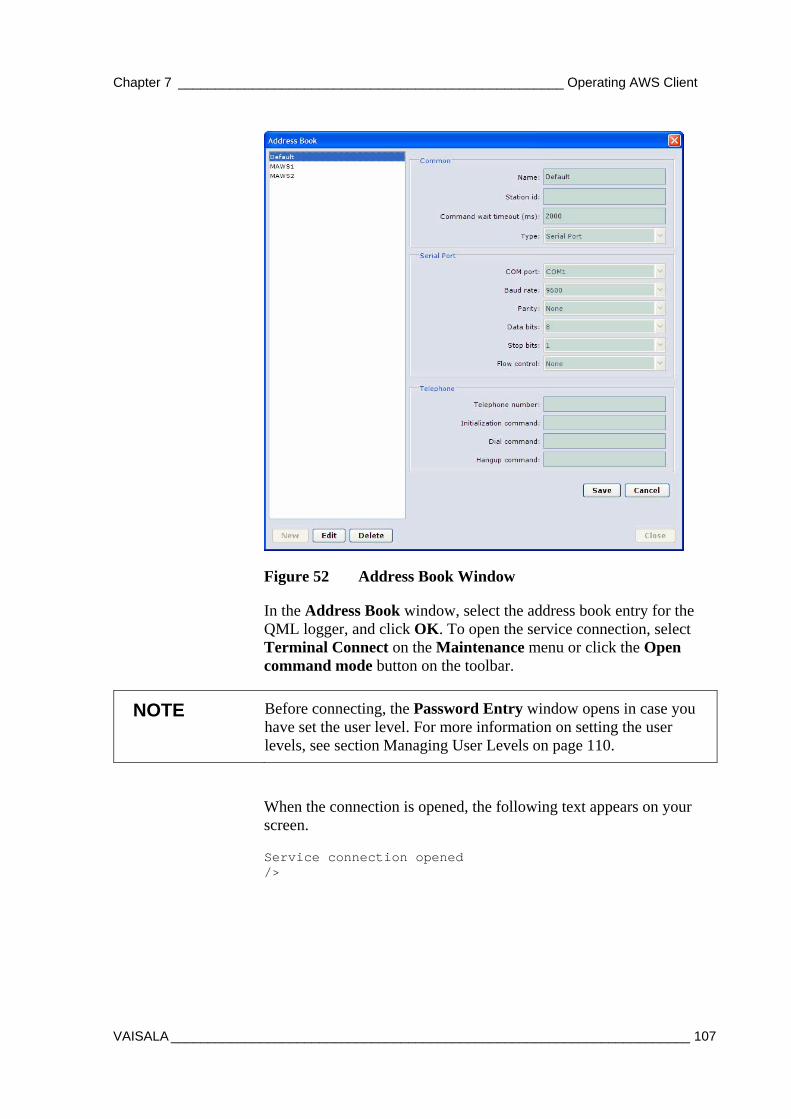
Chapter 7 ____________________________________________________ Operating AWS Client
VAISALA ______________________________________________________________________ 107
Figure 52 Address Book Window
In the Address Book window, select the address book entry for the QML logger, and click OK. To open the service connection, select Terminal Connect on the Maintenance menu or click the Open command mode button on the toolbar.
NOTE Before connecting, the Password Entry window opens in case you have set the user level. For more information on setting the user levels, see section Managing User Levels on page 110.
When the connection is opened, the following text appears on your screen.
Service connection opened />
USER'S GUIDE____________________________________________________________________
108 _________________________________________________________________ M210891EN-A
Giving Commands When you have established the connection to the QML logger, you can use the commands described in Table 30 on page 141 to communicate with the QML logger. Commands are text strings sent from the PC or terminal to the logger.
To open the connection, select Terminal Connect on the Maintenance menu or click the Open command mode button on the toolbar. To close the terminal connection, select Terminal Disconnect on the Maintenance menu or click the Close command mode button on the toolbar. Logging is not affected unless it is stopped using the logstop command. In the closed mode, the serial line will be available for report sending.
NOTE Both open and close commands have to be typed exactly correctly before they can be executed. This means that you cannot use the BACKSPACE key to correct your typing. Simply retype the command and press ENTER to give the command again.
Most of the commands can be used for both setting a value for a parameter and viewing the set value of a parameter.
Type help to get a list of the available commands. Each command must be entered using the correct syntax. You do not have to memorize complex commands since you can view a help text that shows the correct syntax at any time. Simply type help and the command name.
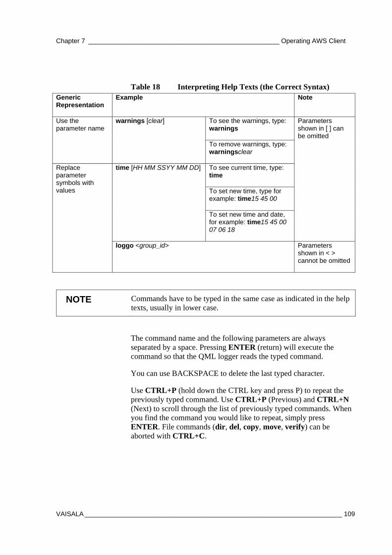
Chapter 7 ____________________________________________________ Operating AWS Client
VAISALA ______________________________________________________________________ 109
Table 18 Interpreting Help Texts (the Correct Syntax) Generic Representation
Example Note
To see the warnings, type: warnings
Use the parameter name
warnings [clear]
To remove warnings, type: warningsclear
To see current time, type: time
To set new time, type for example: time15 45 00
time [HH MM SSYY MM DD]
To set new time and date, for example: time15 45 00 07 06 18
Parameters shown in [ ] can be omitted
Replace parameter symbols with values
loggo <group_id> Parameters shown in < > cannot be omitted
NOTE Commands have to be typed in the same case as indicated in the help texts, usually in lower case.
The command name and the following parameters are always separated by a space. Pressing ENTER (return) will execute the command so that the QML logger reads the typed command.
You can use BACKSPACE to delete the last typed character.
Use CTRL+P (hold down the CTRL key and press P) to repeat the previously typed command. Use CTRL+P (Previous) and CTRL+N (Next) to scroll through the list of previously typed commands. When you find the command you would like to repeat, simply press ENTER. File commands (dir, del, copy, move, verify) can be aborted with CTRL+C.
USER'S GUIDE____________________________________________________________________
110 _________________________________________________________________ M210891EN-A
Closing Service Connection Disconnecting a connection to a QML logger normally closes the service connection as well. If your connection to the QML logger works via a modem, remember to close the line after you finish working with the logger. To close the connection, choose Disconnect from the File menu.
If your connection to the QML logger is direct, you are recommended to close the service connection by entering the close command or selecting Terminal Disconnect on the Maintenance menu. The program closes the service connection automatically after 5 minutes.
Managing User Levels You can use the userlevel command to protect the system from unauthorized use. The system provides three password-protected access levels to the shell commands as well as to the visibility of system data. By default, the user levels are not in use.
CAUTION Improper use of the userlevel command may lead to malfunction of the QML logger.
You can manage user levels with the userlevel command when the service connection is open. The command has the following syntax:
userlevel [level <set/clear>]
where level = 1, 3, or 5 set = Sets the password for a level clear = Clears the password from a level
To check the current setting, give the command alone, without parameters. When you want to change the level, give the command with parameters. When you change the level to a higher one, a password is required. When you change the level to a lower one, a password is not required.
To change the password for the level, give the command with the appropriate level and the set parameter. For this operation, the user

Chapter 7 ____________________________________________________ Operating AWS Client
VAISALA ______________________________________________________________________ 111
level has to be the highest, that is, 5. The new password is effective immediately.
To remove the password for the level, give the command with the appropriate level and the clear parameter. For this operation, the effective user level has to be the highest, that is, 5. The new password is effective immediately.
CAUTION Setting a new or clearing an existing user level is effective only after a reset. When setting a new level or clearing an existing one, be sure to reset the system before closing the service connection. Otherwise, you may not be able to access the system without a cold reset.
To check the allowed commands at a specific level, give the help command. Table 19 below lists the accessible commands in the different user levels. Level 1 provides access to the minimum set of commands and visibility of system parameters. Level 3 provides access to all commands needed for normal administration and commissioning. Level 5 provides access to all commands. For command reference, see Table 30 on page 141.
Table 19 Accessible Commands in Different User Levels User Level Commands Userlevel 1 cd, copy, dir, errors, help, logshow, logshownext,
logshowprev, logstatus, rep, warnings, and zs Userlevel 3 EXTFS, LOGFS, altitude, battery, cd, chmod, copy, del,
dir, errors, ftp, help, ipconfig, logdel, loggo, logshow, logshownext, logshowprev, logstatus, logstop, md, move, net, netif, ntp, paramset, paramsetclear, ping, pslevel, rd, rep, reset, serial, sname, spclear, spset, time, timezone, verify, warnings, winddircal0, zr, and zs
Userlevel 5 All the userlevel 3 commands and the userlevel administrator rights
Modifying Station Settings With AWS Client, you can modify the station settings. When you select the Parameters - Common option from the Settings menu, the Common Parameters window is displayed as shown in Figure 53 on page 112. Table 20 on page 112 lists the items that can be changed.
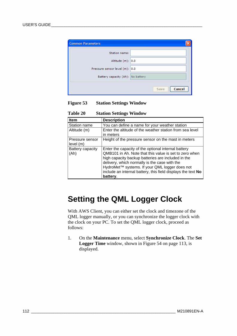
USER'S GUIDE____________________________________________________________________
112 _________________________________________________________________ M210891EN-A
Figure 53 Station Settings Window
Table 20 Station Settings Window Item Description Station name You can define a name for your weather station Altitude (m) Enter the altitude of the weather station from sea level
in meters Pressure sensor level (m)
Height of the pressure sensor on the mast in meters
Battery capacity (Ah)
Enter the capacity of the optional internal battery QMB101 in Ah. Note that this value is set to zero when high capacity backup batteries are included in the delivery, which normally is the case with the HydroMet™ systems. If your QML logger does not include an internal battery, this field displays the text No battery.
Setting the QML Logger Clock With AWS Client, you can either set the clock and timezone of the QML logger manually, or you can synchronize the logger clock with the clock on your PC. To set the QML logger clock, proceed as follows:
1. On the Maintenance menu, select Synchronize Clock. The Set Logger Time window, shown in Figure 54 on page 113, is displayed.
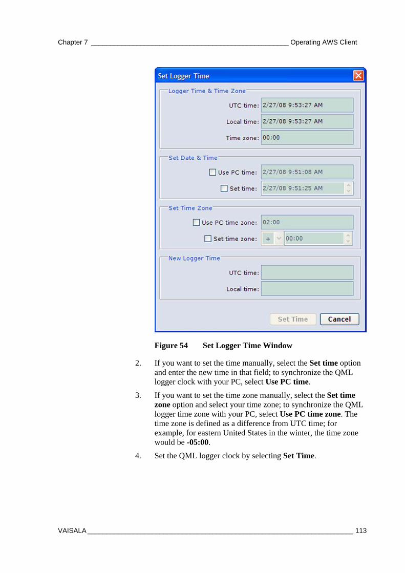
Chapter 7 ____________________________________________________ Operating AWS Client
VAISALA ______________________________________________________________________ 113
Figure 54 Set Logger Time Window
2. If you want to set the time manually, select the Set time option and enter the new time in that field; to synchronize the QML logger clock with your PC, select Use PC time.
3. If you want to set the time zone manually, select the Set time zone option and select your time zone; to synchronize the QML logger time zone with your PC, select Use PC time zone. The time zone is defined as a difference from UTC time; for example, for eastern United States in the winter, the time zone would be -05:00.
4. Set the QML logger clock by selecting Set Time.
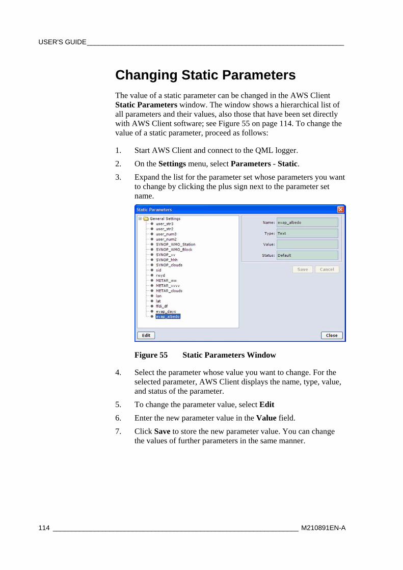
USER'S GUIDE____________________________________________________________________
114 _________________________________________________________________ M210891EN-A
Changing Static Parameters The value of a static parameter can be changed in the AWS Client Static Parameters window. The window shows a hierarchical list of all parameters and their values, also those that have been set directly with AWS Client software; see Figure 55 on page 114. To change the value of a static parameter, proceed as follows:
1. Start AWS Client and connect to the QML logger.
2. On the Settings menu, select Parameters - Static.
3. Expand the list for the parameter set whose parameters you want to change by clicking the plus sign next to the parameter set name.
Figure 55 Static Parameters Window
4. Select the parameter whose value you want to change. For the selected parameter, AWS Client displays the name, type, value, and status of the parameter.
5. To change the parameter value, select Edit
6. Enter the new parameter value in the Value field.
7. Click Save to store the new parameter value. You can change the values of further parameters in the same manner.
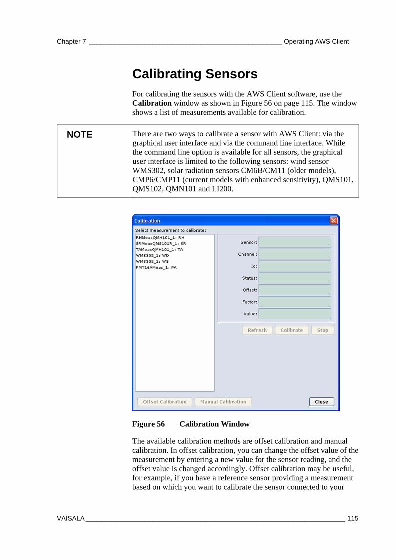
Chapter 7 ____________________________________________________ Operating AWS Client
VAISALA ______________________________________________________________________ 115
Calibrating Sensors For calibrating the sensors with the AWS Client software, use the Calibration window as shown in Figure 56 on page 115. The window shows a list of measurements available for calibration.
NOTE There are two ways to calibrate a sensor with AWS Client: via the graphical user interface and via the command line interface. While the command line option is available for all sensors, the graphical user interface is limited to the following sensors: wind sensor WMS302, solar radiation sensors CM6B/CM11 (older models), CMP6/CMP11 (current models with enhanced sensitivity), QMS101, QMS102, QMN101 and LI200.
Figure 56 Calibration Window
The available calibration methods are offset calibration and manual calibration. In offset calibration, you can change the offset value of the measurement by entering a new value for the sensor reading, and the offset value is changed accordingly. Offset calibration may be useful, for example, if you have a reference sensor providing a measurement based on which you want to calibrate the sensor connected to your
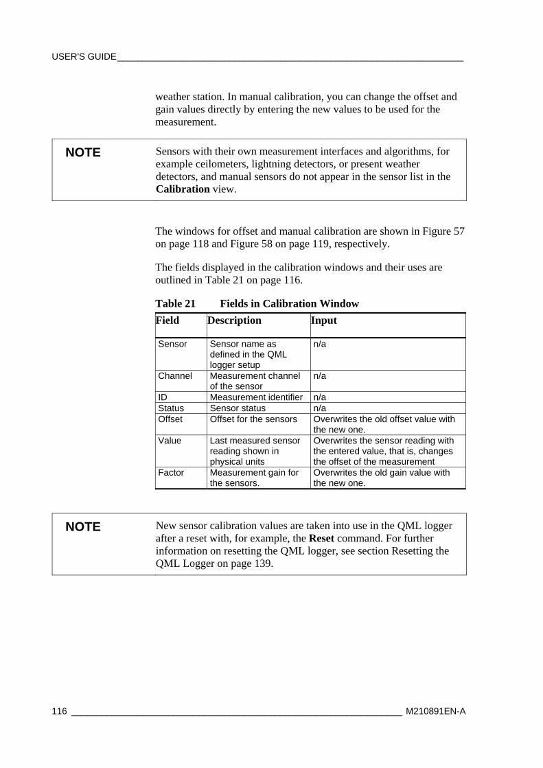
USER'S GUIDE____________________________________________________________________
116 _________________________________________________________________ M210891EN-A
weather station. In manual calibration, you can change the offset and gain values directly by entering the new values to be used for the measurement.
NOTE Sensors with their own measurement interfaces and algorithms, for example ceilometers, lightning detectors, or present weather detectors, and manual sensors do not appear in the sensor list in the Calibration view.
The windows for offset and manual calibration are shown in Figure 57 on page 118 and Figure 58 on page 119, respectively.
The fields displayed in the calibration windows and their uses are outlined in Table 21 on page 116.
Table 21 Fields in Calibration Window Field Description Input
Sensor Sensor name as defined in the QML logger setup
n/a
Channel Measurement channel of the sensor
n/a
ID Measurement identifier n/a Status Sensor status n/a Offset Offset for the sensors Overwrites the old offset value with
the new one. Value Last measured sensor
reading shown in physical units
Overwrites the sensor reading with the entered value, that is, changes the offset of the measurement
Factor Measurement gain for the sensors.
Overwrites the old gain value with the new one.
NOTE New sensor calibration values are taken into use in the QML logger after a reset with, for example, the Reset command. For further information on resetting the QML logger, see section Resetting the QML Logger on page 139.
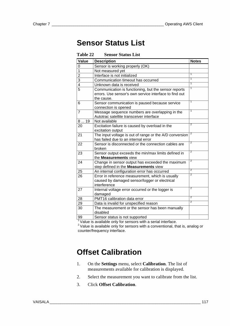
Chapter 7 ____________________________________________________ Operating AWS Client
VAISALA ______________________________________________________________________ 117
Sensor Status List Table 22 Sensor Status List Value Description Notes 0 Sensor is working properly (OK) 1 Not measured yet 2 Interface is not initialized 1 3 Communication timeout has occurred 1 4 Unknown data is received 1 5 Communication is functioning, but the sensor reports
errors. Use sensor's own service interface to find out the cause.
1
6 Sensor communication is paused because service connection is opened
1
7 Message sequence numbers are overlapping in the Autotrac satellite transceiver interface
1
8 ... 19 Not available 20 Excitation failure is caused by overload in the
excitation output 2
21 The input voltage is out of range or the A/D conversion has failed due to an internal error
2
22 Sensor is disconnected or the connection cables are broken
2
23 Sensor output exceeds the min/max limits defined in the Measurements view
2
24 Change in sensor output has exceeded the maximum step defined in the Measurements view
2
25 An internal configuration error has occurred 2 26 Error in reference measurement, which is usually
caused by damaged sensor/logger or electrical interference
2
27 Internal voltage error occurred or the logger is damaged
2
28 PMT16 calibration data error 2 29 Data is invalid for unspecified reason 2 30 The measurement or the sensor has been manually
disabled
99 Sensor status is not supported 1 Value is available only for sensors with a serial interface. 2 Value is available only for sensors with a conventional, that is, analog or counter/frequency interface.
Offset Calibration 1. On the Settings menu, select Calibration. The list of
measurements available for calibration is displayed.
2. Select the measurement you want to calibrate from the list.
3. Click Offset Calibration.
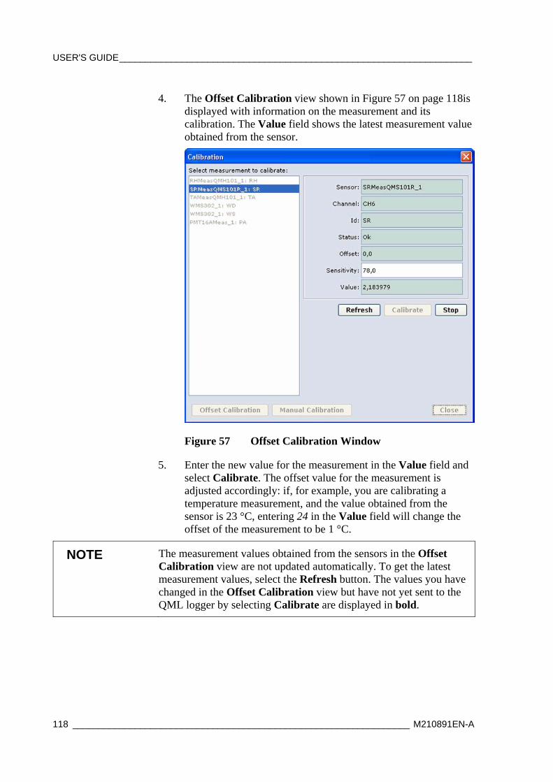
USER'S GUIDE____________________________________________________________________
118 _________________________________________________________________ M210891EN-A
4. The Offset Calibration view shown in Figure 57 on page 118is displayed with information on the measurement and its calibration. The Value field shows the latest measurement value obtained from the sensor.
Figure 57 Offset Calibration Window
5. Enter the new value for the measurement in the Value field and select Calibrate. The offset value for the measurement is adjusted accordingly: if, for example, you are calibrating a temperature measurement, and the value obtained from the sensor is 23 °C, entering 24 in the Value field will change the offset of the measurement to be 1 °C.
NOTE The measurement values obtained from the sensors in the Offset Calibration view are not updated automatically. To get the latest measurement values, select the Refresh button. The values you have changed in the Offset Calibration view but have not yet sent to the QML logger by selecting Calibrate are displayed in bold.
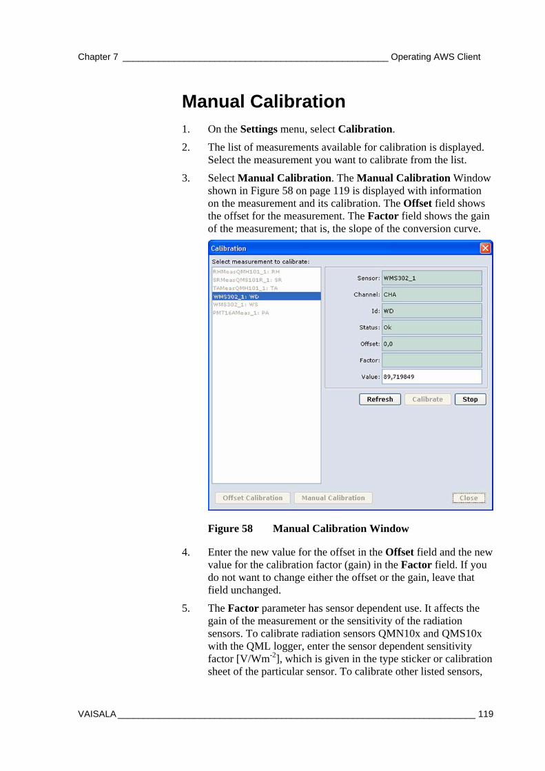
Chapter 7 ____________________________________________________ Operating AWS Client
VAISALA ______________________________________________________________________ 119
Manual Calibration 1. On the Settings menu, select Calibration.
2. The list of measurements available for calibration is displayed. Select the measurement you want to calibrate from the list.
3. Select Manual Calibration. The Manual Calibration Window shown in Figure 58 on page 119 is displayed with information on the measurement and its calibration. The Offset field shows the offset for the measurement. The Factor field shows the gain of the measurement; that is, the slope of the conversion curve.
Figure 58 Manual Calibration Window
4. Enter the new value for the offset in the Offset field and the new value for the calibration factor (gain) in the Factor field. If you do not want to change either the offset or the gain, leave that field unchanged.
5. The Factor parameter has sensor dependent use. It affects the gain of the measurement or the sensitivity of the radiation sensors. To calibrate radiation sensors QMN10x and QMS10x with the QML logger, enter the sensor dependent sensitivity factor [V/Wm-2], which is given in the type sticker or calibration sheet of the particular sensor. To calibrate other listed sensors,
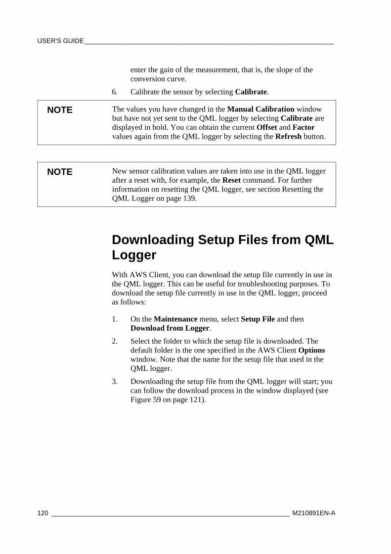
USER'S GUIDE____________________________________________________________________
120 _________________________________________________________________ M210891EN-A
enter the gain of the measurement, that is, the slope of the conversion curve.
6. Calibrate the sensor by selecting Calibrate.
NOTE The values you have changed in the Manual Calibration window but have not yet sent to the QML logger by selecting Calibrate are displayed in bold. You can obtain the current Offset and Factor values again from the QML logger by selecting the Refresh button.
NOTE New sensor calibration values are taken into use in the QML logger after a reset with, for example, the Reset command. For further information on resetting the QML logger, see section Resetting the QML Logger on page 139.
Downloading Setup Files from QML Logger With AWS Client, you can download the setup file currently in use in the QML logger. This can be useful for troubleshooting purposes. To download the setup file currently in use in the QML logger, proceed as follows:
1. On the Maintenance menu, select Setup File and then Download from Logger.
2. Select the folder to which the setup file is downloaded. The default folder is the one specified in the AWS Client Options window. Note that the name for the setup file that used in the QML logger.
3. Downloading the setup file from the QML logger will start; you can follow the download process in the window displayed (see Figure 59 on page 121).
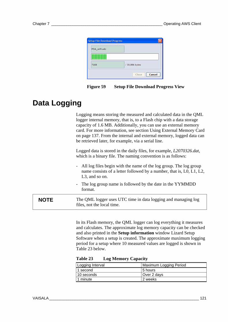
Chapter 7 ____________________________________________________ Operating AWS Client
VAISALA ______________________________________________________________________ 121
Figure 59 Setup File Download Progress View
Data Logging Logging means storing the measured and calculated data in the QML logger internal memory, that is, to a Flash chip with a data storage capacity of 1.6 MB. Additionally, you can use an external memory card. For more information, see section Using External Memory Card on page 137. From the internal and external memory, logged data can be retrieved later, for example, via a serial line.
Logged data is stored in the daily files, for example, L2070326.dat, which is a binary file. The naming convention is as follows:
- All log files begin with the name of the log group. The log group name consists of a letter followed by a number, that is, L0, L1, L2, L3, and so on.
- The log group name is followed by the date in the YYMMDD format.
NOTE The QML logger uses UTC time in data logging and managing log files, not the local time.
In its Flash memory, the QML logger can log everything it measures and calculates. The approximate log memory capacity can be checked and also printed in the Setup information window Lizard Setup Software when a setup is created. The approximate maximum logging period for a setup where 10 measured values are logged is shown in Table 23 below.
Table 23 Log Memory Capacity Logging Interval Maximum Logging Period 1 second 5 hours 10 seconds Over 2 days 1 minute 2 weeks
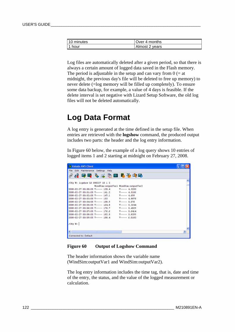
USER'S GUIDE____________________________________________________________________
122 _________________________________________________________________ M210891EN-A
10 minutes Over 4 months 1 hour Almost 2 years
Log files are automatically deleted after a given period, so that there is always a certain amount of logged data saved in the Flash memory. The period is adjustable in the setup and can vary from 0 (= at midnight, the previous day's file will be deleted to free up memory) to never delete (=log memory will be filled up completely). To ensure some data backup, for example, a value of 4 days is feasible. If the delete interval is set negative with Lizard Setup Software, the old log files will not be deleted automatically.
Log Data Format A log entry is generated at the time defined in the setup file. When entries are retrieved with the logshow command, the produced output includes two parts: the header and the log entry information.
In Figure 60 below, the example of a log query shows 10 entries of logged items 1 and 2 starting at midnight on February 27, 2008.
Figure 60 Output of Logshow Command
The header information shows the variable name (WindSim:outputVar1 and WindSim:outputVar2).
The log entry information includes the time tag, that is, date and time of the entry, the status, and the value of the logged measurement or calculation.
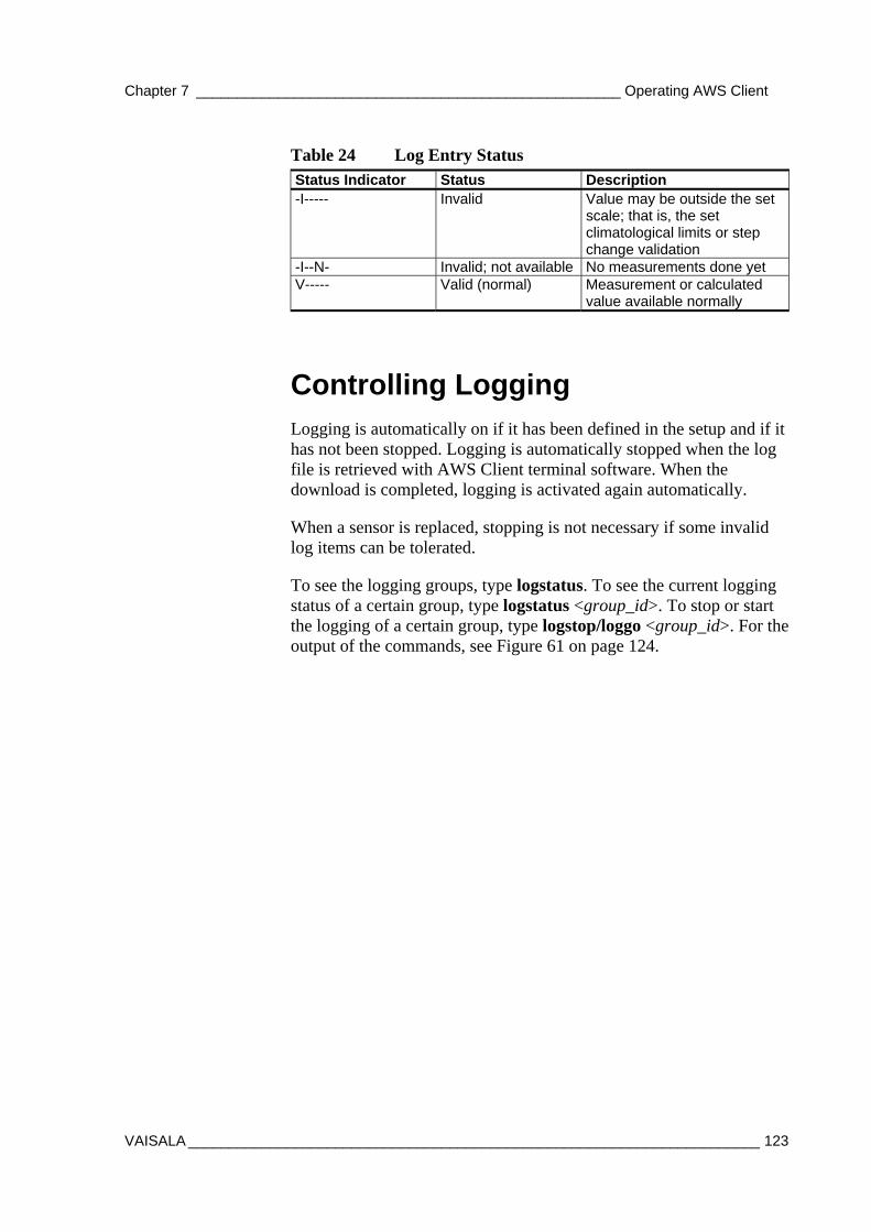
Chapter 7 ____________________________________________________ Operating AWS Client
VAISALA ______________________________________________________________________ 123
Table 24 Log Entry Status Status Indicator Status Description -I----- Invalid Value may be outside the set
scale; that is, the set climatological limits or step change validation
-I--N- Invalid; not available No measurements done yet V----- Valid (normal) Measurement or calculated
value available normally
Controlling Logging Logging is automatically on if it has been defined in the setup and if it has not been stopped. Logging is automatically stopped when the log file is retrieved with AWS Client terminal software. When the download is completed, logging is activated again automatically.
When a sensor is replaced, stopping is not necessary if some invalid log items can be tolerated.
To see the logging groups, type logstatus. To see the current logging status of a certain group, type logstatus <group_id>. To stop or start the logging of a certain group, type logstop/loggo <group_id>. For the output of the commands, see Figure 61 on page 124.
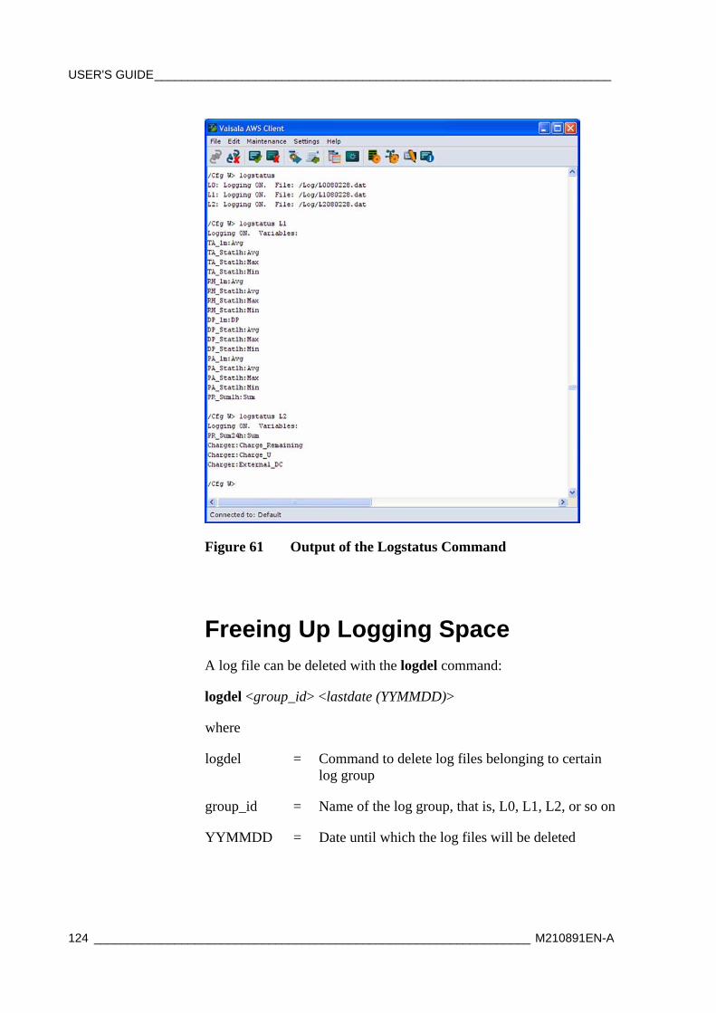
USER'S GUIDE____________________________________________________________________
124 _________________________________________________________________ M210891EN-A
Figure 61 Output of the Logstatus Command
Freeing Up Logging Space A log file can be deleted with the logdel command:
logdel <group_id> <lastdate (YYMMDD)>
where
logdel = Command to delete log files belonging to certain log group
group_id = Name of the log group, that is, L0, L1, L2, or so on
YYMMDD = Date until which the log files will be deleted
Chapter 7 ____________________________________________________ Operating AWS Client
VAISALA ______________________________________________________________________ 125
Example:
/ > logdel L2 d070910 To erase all data in the log system, type LOGFSERASE. This command erases the whole Flash memory and resets the QML logger. The command LOGFSERASE is necessary to free space for new log data.
CAUTION Erasing the log memory with LOGFSERASE command is strongly recommended when changing a setup. First, load a new setup and make sure it is operating correctly. Check that you have retrieved all the necessary information from the log memory, and then erase the log memory.
Working with Data Log Files To view the logged data, you first need to open the service connection, download the files from the QML logger to your PC and convert them to CSV (Comma Separated Value) format. After the conversion, you can view the files, for example, in Microsoft Excel.
Before you start downloading files, you need to open a connection to the QML logger by selecting the Connect option from the File menu or clicking the Open connection button on the toolbar. For more information on opening the connection, see section Opening Service Connection on page 106.
Selecting Files for Downloading When you have opened the service connection, you need to select the data log files you want to download. Choose the Log Files - Download from Logger option from the Maintenance menu. The Log File Download window is displayed as shown in Figure 62 on page 126.
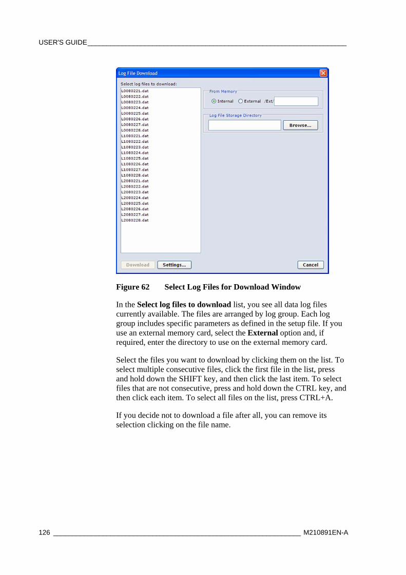
USER'S GUIDE____________________________________________________________________
126 _________________________________________________________________ M210891EN-A
Figure 62 Select Log Files for Download Window
In the Select log files to download list, you see all data log files currently available. The files are arranged by log group. Each log group includes specific parameters as defined in the setup file. If you use an external memory card, select the External option and, if required, enter the directory to use on the external memory card.
Select the files you want to download by clicking them on the list. To select multiple consecutive files, click the first file in the list, press and hold down the SHIFT key, and then click the last item. To select files that are not consecutive, press and hold down the CTRL key, and then click each item. To select all files on the list, press CTRL+A.
If you decide not to download a file after all, you can remove its selection clicking on the file name.
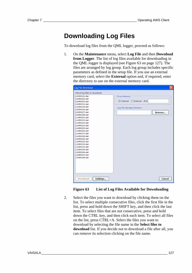
Chapter 7 ____________________________________________________ Operating AWS Client
VAISALA ______________________________________________________________________ 127
Downloading Log Files To download log files from the QML logger, proceed as follows:
1. On the Maintenance menu, select Log File and then Download from Logger. The list of log files available for downloading in the QML logger is displayed (see Figure 63 on page 127). The files are arranged by log group. Each log group includes specific parameters as defined in the setup file. If you use an external memory card, select the External option and, if required, enter the directory to use on the external memory card.
Figure 63 List of Log Files Available for Downloading
2. Select the files you want to download by clicking them on the list. To select multiple consecutive files, click the first file in the list, press and hold down the SHIFT key, and then click the last item. To select files that are not consecutive, press and hold down the CTRL key, and then click each item. To select all files on the list, press CTRL+A. Select the files you want to download by selecting the file name in the Select files to download list. If you decide not to download a file after all, you can remove its selection clicking on the file name.
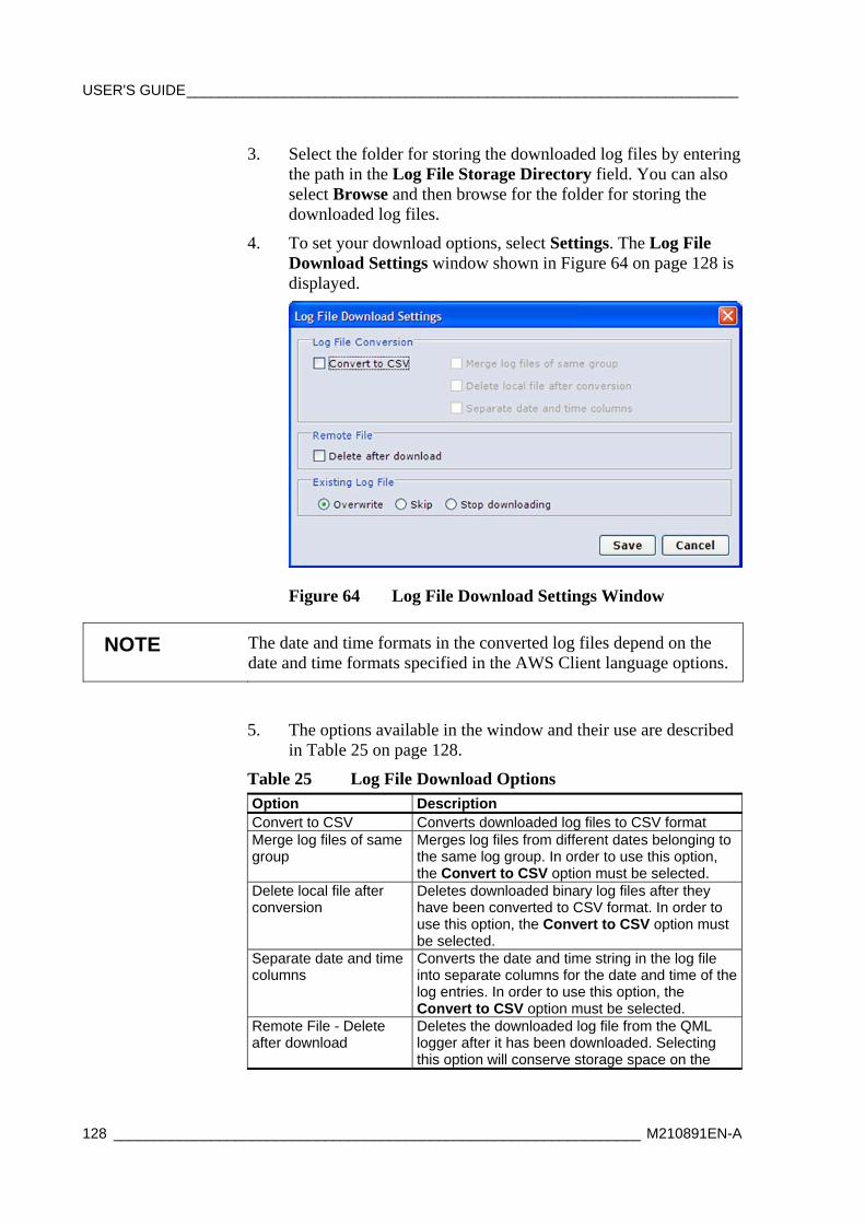
USER'S GUIDE____________________________________________________________________
128 _________________________________________________________________ M210891EN-A
3. Select the folder for storing the downloaded log files by entering the path in the Log File Storage Directory field. You can also select Browse and then browse for the folder for storing the downloaded log files.
4. To set your download options, select Settings. The Log File Download Settings window shown in Figure 64 on page 128 is displayed.
Figure 64 Log File Download Settings Window
NOTE The date and time formats in the converted log files depend on the date and time formats specified in the AWS Client language options.
5. The options available in the window and their use are described in Table 25 on page 128.
Table 25 Log File Download Options Option Description Convert to CSV Converts downloaded log files to CSV format Merge log files of same group
Merges log files from different dates belonging to the same log group. In order to use this option, the Convert to CSV option must be selected.
Delete local file after conversion
Deletes downloaded binary log files after they have been converted to CSV format. In order to use this option, the Convert to CSV option must be selected.
Separate date and time columns
Converts the date and time string in the log file into separate columns for the date and time of the log entries. In order to use this option, the Convert to CSV option must be selected.
Remote File - Delete after download
Deletes the downloaded log file from the QML logger after it has been downloaded. Selecting this option will conserve storage space on the
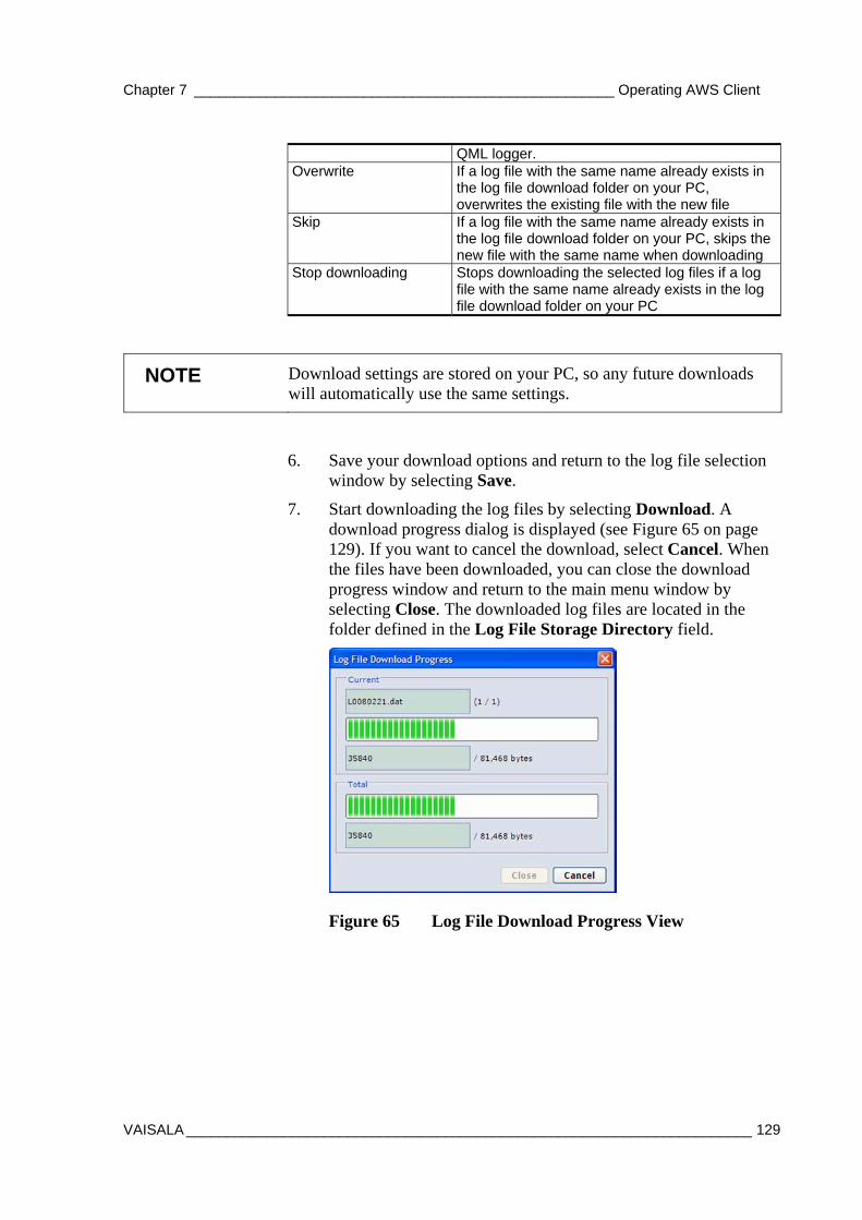
Chapter 7 ____________________________________________________ Operating AWS Client
VAISALA ______________________________________________________________________ 129
QML logger. Overwrite If a log file with the same name already exists in
the log file download folder on your PC, overwrites the existing file with the new file
Skip If a log file with the same name already exists in the log file download folder on your PC, skips the new file with the same name when downloading
Stop downloading Stops downloading the selected log files if a log file with the same name already exists in the log file download folder on your PC
NOTE Download settings are stored on your PC, so any future downloads will automatically use the same settings.
6. Save your download options and return to the log file selection window by selecting Save.
7. Start downloading the log files by selecting Download. A download progress dialog is displayed (see Figure 65 on page 129). If you want to cancel the download, select Cancel. When the files have been downloaded, you can close the download progress window and return to the main menu window by selecting Close. The downloaded log files are located in the folder defined in the Log File Storage Directory field.
Figure 65 Log File Download Progress View
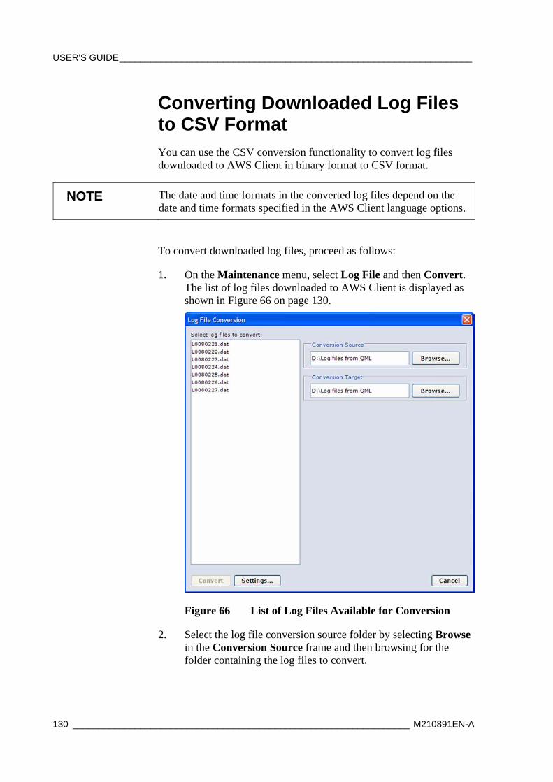
USER'S GUIDE____________________________________________________________________
130 _________________________________________________________________ M210891EN-A
Converting Downloaded Log Files to CSV Format You can use the CSV conversion functionality to convert log files downloaded to AWS Client in binary format to CSV format.
NOTE The date and time formats in the converted log files depend on the date and time formats specified in the AWS Client language options.
To convert downloaded log files, proceed as follows:
1. On the Maintenance menu, select Log File and then Convert. The list of log files downloaded to AWS Client is displayed as shown in Figure 66 on page 130.
Figure 66 List of Log Files Available for Conversion
2. Select the log file conversion source folder by selecting Browse in the Conversion Source frame and then browsing for the folder containing the log files to convert.
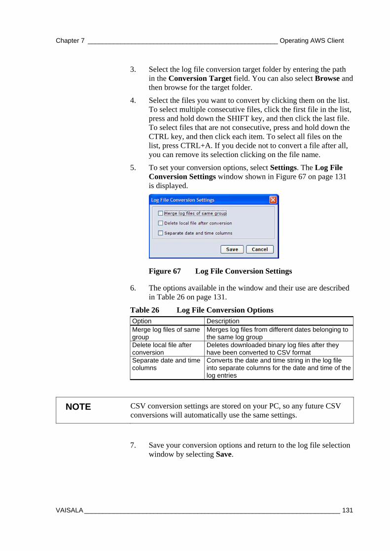
Chapter 7 ____________________________________________________ Operating AWS Client
VAISALA ______________________________________________________________________ 131
3. Select the log file conversion target folder by entering the path in the Conversion Target field. You can also select Browse and then browse for the target folder.
4. Select the files you want to convert by clicking them on the list. To select multiple consecutive files, click the first file in the list, press and hold down the SHIFT key, and then click the last file. To select files that are not consecutive, press and hold down the CTRL key, and then click each item. To select all files on the list, press CTRL+A. If you decide not to convert a file after all, you can remove its selection clicking on the file name.
5. To set your conversion options, select Settings. The Log File Conversion Settings window shown in Figure 67 on page 131 is displayed.
Figure 67 Log File Conversion Settings
6. The options available in the window and their use are described in Table 26 on page 131.
Table 26 Log File Conversion Options Option Description Merge log files of same group
Merges log files from different dates belonging to the same log group
Delete local file after conversion
Deletes downloaded binary log files after they have been converted to CSV format
Separate date and time columns
Converts the date and time string in the log file into separate columns for the date and time of the log entries
NOTE CSV conversion settings are stored on your PC, so any future CSV conversions will automatically use the same settings.
7. Save your conversion options and return to the log file selection window by selecting Save.
USER'S GUIDE____________________________________________________________________
132 _________________________________________________________________ M210891EN-A
8. Convert the selected files to CSV format by selecting Convert. The converted log files are located in the folder specified in the Conversion Target field.
Auto Downloading Log Files You can run the AWS Client terminal program in auto-download mode. This mode allows you to download log files automatically according to a user-defined schedule.
Before you change the application to the auto-download mode, a schedule must be defined. This is done in the window appearing when selecting Settings - Auto Download. The Auto Download Settings window is shown in Figure 68 on page 133.
In the Auto Download Settings window, you can define which station to connect to, when, and which log files to download, and where to store them.
NOTE To enable auto downloading you must have AWS Client running continuously. In addition, if you are using a serial line connection, the COM port must be free and assigned for AWS Client.

Chapter 7 ____________________________________________________ Operating AWS Client
VAISALA ______________________________________________________________________ 133
Figure 68 Auto Download Settings Window
The options available in the window and their use are described in Table 27 on page 133.
Table 27 Settings in Auto Download Settings Window Option Description Address book entry Specifies the QML logger from which log files
are to be downloaded. Polling frequency Specified the frequency at which log files are to
be downloaded. The mutually exclusive options are: Never. AWS Client will never attempt to download log files. Daily. Logs are downloaded daily at a certain time from the selected station. Weekly. Logs are downloaded weekly at a certain time on a certain day of the week from the selected station. Selecting this option will activate the Poll day field, which accepts values from Sun to Sat. Monthly. Logs are downloaded monthly at a certain time of a day of a month.from the selected station. Selecting this option will activate the Poll day field, which accepts values
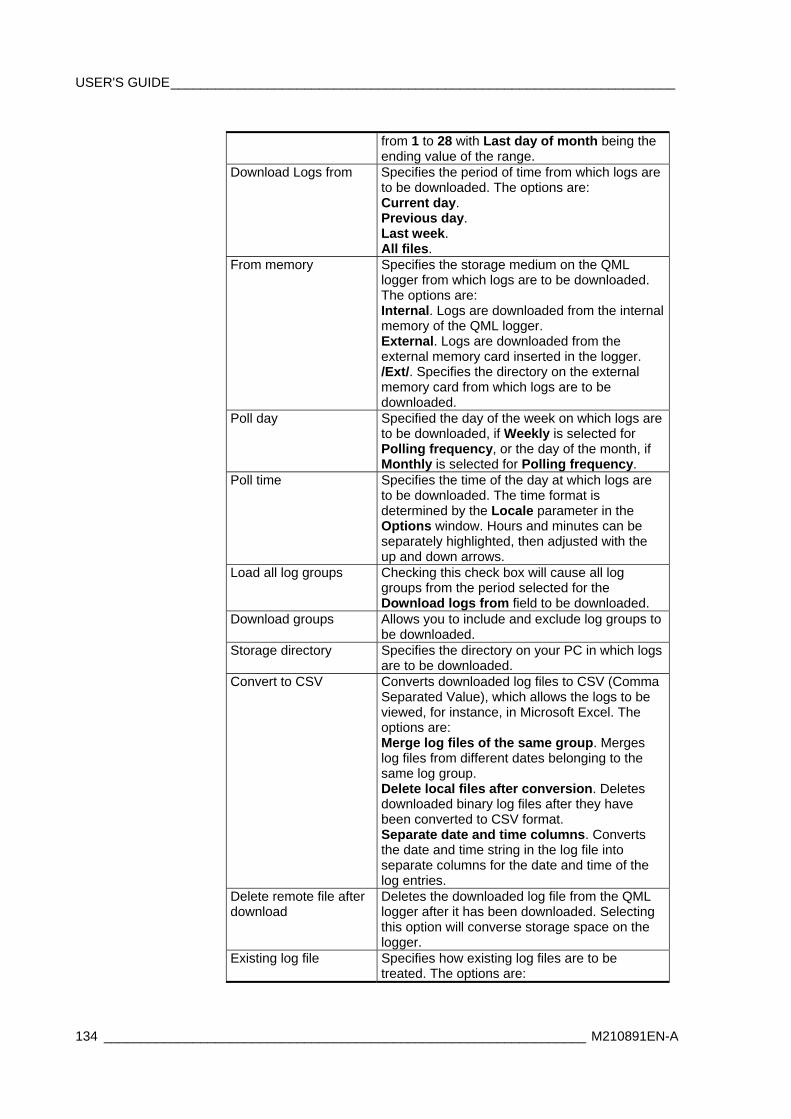
USER'S GUIDE____________________________________________________________________
134 _________________________________________________________________ M210891EN-A
from 1 to 28 with Last day of month being the ending value of the range.
Download Logs from Specifies the period of time from which logs are to be downloaded. The options are: Current day. Previous day. Last week. All files.
From memory Specifies the storage medium on the QML logger from which logs are to be downloaded. The options are: Internal. Logs are downloaded from the internal memory of the QML logger. External. Logs are downloaded from the external memory card inserted in the logger. /Ext/. Specifies the directory on the external memory card from which logs are to be downloaded.
Poll day Specified the day of the week on which logs are to be downloaded, if Weekly is selected for Polling frequency, or the day of the month, if Monthly is selected for Polling frequency.
Poll time Specifies the time of the day at which logs are to be downloaded. The time format is determined by the Locale parameter in the Options window. Hours and minutes can be separately highlighted, then adjusted with the up and down arrows.
Load all log groups Checking this check box will cause all log groups from the period selected for the Download logs from field to be downloaded.
Download groups Allows you to include and exclude log groups to be downloaded.
Storage directory Specifies the directory on your PC in which logs are to be downloaded.
Convert to CSV Converts downloaded log files to CSV (Comma Separated Value), which allows the logs to be viewed, for instance, in Microsoft Excel. The options are: Merge log files of the same group. Merges log files from different dates belonging to the same log group. Delete local files after conversion. Deletes downloaded binary log files after they have been converted to CSV format. Separate date and time columns. Converts the date and time string in the log file into separate columns for the date and time of the log entries.
Delete remote file after download
Deletes the downloaded log file from the QML logger after it has been downloaded. Selecting this option will converse storage space on the logger.
Existing log file Specifies how existing log files are to be treated. The options are:
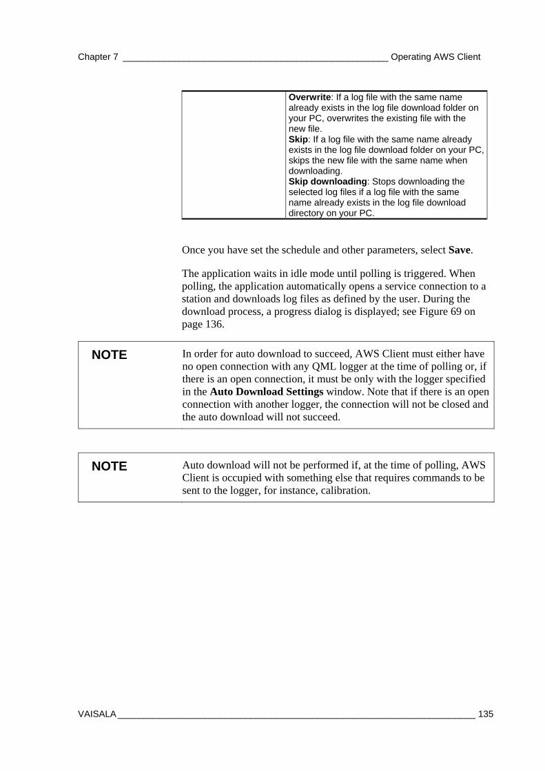
Chapter 7 ____________________________________________________ Operating AWS Client
VAISALA ______________________________________________________________________ 135
Overwrite: If a log file with the same name already exists in the log file download folder on your PC, overwrites the existing file with the new file. Skip: If a log file with the same name already exists in the log file download folder on your PC, skips the new file with the same name when downloading. Skip downloading: Stops downloading the selected log files if a log file with the same name already exists in the log file download directory on your PC.
Once you have set the schedule and other parameters, select Save.
The application waits in idle mode until polling is triggered. When polling, the application automatically opens a service connection to a station and downloads log files as defined by the user. During the download process, a progress dialog is displayed; see Figure 69 on page 136.
NOTE In order for auto download to succeed, AWS Client must either have no open connection with any QML logger at the time of polling or, if there is an open connection, it must be only with the logger specified in the Auto Download Settings window. Note that if there is an open connection with another logger, the connection will not be closed and the auto download will not succeed.
NOTE Auto download will not be performed if, at the time of polling, AWS Client is occupied with something else that requires commands to be sent to the logger, for instance, calibration.
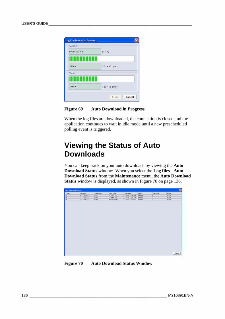
USER'S GUIDE____________________________________________________________________
136 _________________________________________________________________ M210891EN-A
Figure 69 Auto Download in Progress
When the log files are downloaded, the connection is closed and the application continues to wait in idle mode until a new prescheduled polling event is triggered.
Viewing the Status of Auto Downloads You can keep track on your auto downloads by viewing the Auto Download Status window. When you select the Log files - Auto Download Status from the Maintenance menu, the Auto Download Status window is displayed, as shown in Figure 70 on page 136.
Figure 70 Auto Download Status Window
Chapter 7 ____________________________________________________ Operating AWS Client
VAISALA ______________________________________________________________________ 137
For each download triggered by the auto download settings, the following information is displayed, as described in Table 28 on page 137.
Table 28 Fields in Auto Download Status Window Option Description Event Status of the download. The options are: OK: Auto
download was successfully completed. Failed: Auto download failed. Cancelled: Auto download was cancelled.
Poll time Time the auto download started. Frequency Polling frequency value set for the download. Logs from Time period from which logs are downloaded. Completed Time of completion for the download. Entry Station from which logs are downloaded. File count Number of log files downloaded. Bytes Size of the download.
Using External Memory Card The external memory card is used to store log files that have been copied or moved from the internal log directory. The data can be retrieved from the external memory card via terminal connection or by switching the memory card with an empty one.
NOTE If the Compact Flash memory card has not been formatted, it must be formatted before use.
In MAWS versions 6.00 and later, you are recommended to format the card in a Windows PC. The file system to use is FAT (not FAT32). Also, do not select the quick format option.
To format the CF card in the QML logger, insert it into the CF slot of the QML logger. Give the EXTFSERASE command. After the card has been formatted, you can remove it from the slot.
The external memory card can be removed from the QML logger for data retrieval without interruptions to operations. The logger copies data from the internal log directory to the memory card daily at midnight, the default time is 00:00:30. Data is being written when the LED on the logger cover to the left of the external memory card is constantly on.
USER'S GUIDE____________________________________________________________________
138 _________________________________________________________________ M210891EN-A
CAUTION The memory card must not be removed from the QML logger while data is being written, or the data may be lost. By default, data is transmitted to the memory card each day at 00:00:30.
When a new memory card is inserted into the QML logger, the software checks that the card is ready for use. The status of the memory card is indicated by a LED. Table 29 below describes the different blinking sequences and the card conditions they indicate.
Table 29 LED Blinking Sequencies and Card Status Options Blinking Sequence Card Status Long-long Card is OK Constantly on Data is being written Short-short-short for 5 seconds Card is unformatted or corrupted
Automatic Erase from External Memory Card The log group specific setting Number of days to preserve log files, specified in MAWS Lizard, also affects the files stored to the external memory card. The functionality is the same as for internal log memory:
- Files older than the selected value [days] will be deleted automatically
- Files are not erased, that is, the automatic clean up is disabled
When files are stored to the external memory card, the internal memory is used as the working memory for storing the log files of the current day. These working files are moved to the external card each day just after midnight when the new files have been created for writing.

Chapter 7 ____________________________________________________ Operating AWS Client
VAISALA ______________________________________________________________________ 139
Resetting the QML Logger The Reset command is used for resetting the QML logger. You can either reset the logger immediately or after a specified delay. To reset the logger, proceed as follows:
1. On the Maintenance menu, select Reset.
2. The Reset menu includes two options for resetting the logger:
1. To reset the logger immediately, select Immediate. The logger reset begins.
2. To reset the logger after a specified delay, select Delayed. The Delayed Reset prompt is displayed.
Figure 71 Delayed Reset Prompt
1. In the Reset delay (s) field, enter the delay (in seconds) after which you want the logger to be reset. The logger reset will begin after the specified delay has elapsed.
2. Select OK. The logger reset will start after the delay specified in the previous step.
Once the reset is complete and the setup is running without problems, the AWS Client terminal window displays the text Setup running ok, and the logger is again ready for use.
Reset Using the Reset Button As an alternative to resetting the QML logger using AWS Client, you can also press the reset button, indicated by number 1 in Figure 72 on page 140.
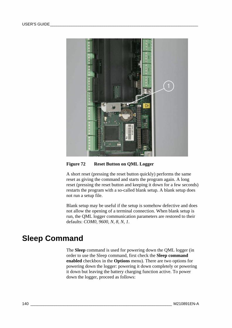
USER'S GUIDE____________________________________________________________________
140 _________________________________________________________________ M210891EN-A
Figure 72 Reset Button on QML Logger
A short reset (pressing the reset button quickly) performs the same reset as giving the command and starts the program again. A long reset (pressing the reset button and keeping it down for a few seconds) restarts the program with a so-called blank setup. A blank setup does not run a setup file.
Blank setup may be useful if the setup is somehow defective and does not allow the opening of a terminal connection. When blank setup is run, the QML logger communication parameters are restored to their defaults: COM0, 9600, N, 8, N, 1.
Sleep Command The Sleep command is used for powering down the QML logger (in order to use the Sleep command, first check the Sleep command enabled checkbox in the Options menu). There are two options for powering down the logger: powering it down completely or powering it down but leaving the battery charging function active. To power down the logger, proceed as follows:
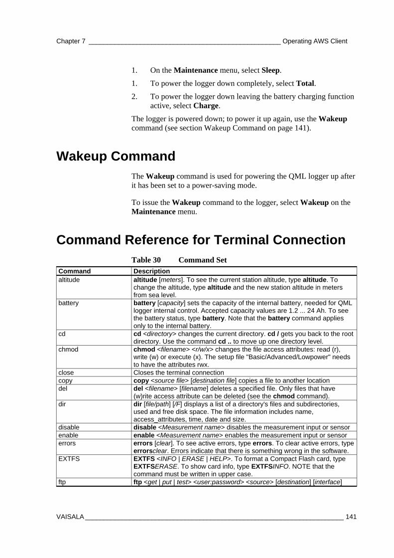
Chapter 7 ____________________________________________________ Operating AWS Client
VAISALA ______________________________________________________________________ 141
1. On the Maintenance menu, select Sleep.
1. To power the logger down completely, select Total.
2. To power the logger down leaving the battery charging function active, select Charge.
The logger is powered down; to power it up again, use the Wakeup command (see section Wakeup Command on page 141).
Wakeup Command The Wakeup command is used for powering the QML logger up after it has been set to a power-saving mode.
To issue the Wakeup command to the logger, select Wakeup on the Maintenance menu.
Command Reference for Terminal Connection Table 30 Command Set
Command Description altitude altitude [meters]. To see the current station altitude, type altitude. To
change the altitude, type altitude and the new station altitude in meters from sea level.
battery battery [capacity] sets the capacity of the internal battery, needed for QML logger internal control. Accepted capacity values are 1.2 ... 24 Ah. To see the battery status, type battery. Note that the battery command applies only to the internal battery.
cd cd <directory> changes the current directory. cd / gets you back to the root directory. Use the command cd .. to move up one directory level.
chmod chmod <filename> <r/w/x> changes the file access attributes: read (r), write (w) or execute (x). The setup file "Basic/Advanced/Lowpower" needs to have the attributes rwx.
close Closes the terminal connection copy copy <source file> [destination file] copies a file to another location del del <filename> [filename] deletes a specified file. Only files that have
(w)rite access attribute can be deleted (see the chmod command). dir dir [file/path] [/F] displays a list of a directory's files and subdirectories,
used and free disk space. The file information includes name, access_attributes, time, date and size.
disable disable <Measurement name> disables the measurement input or sensor enable enable <Measurement name> enables the measurement input or sensor errors errors [clear]. To see active errors, type errors. To clear active errors, type
errorsclear. Errors indicate that there is something wrong in the software. EXTFS EXTFS <INFO | ERASE | HELP>. To format a Compact Flash card, type
EXTFSERASE. To show card info, type EXTFSINFO. NOTE that the command must be written in upper case.
ftp ftp <get | put | test> <user:password> <source> [destination] [interface]
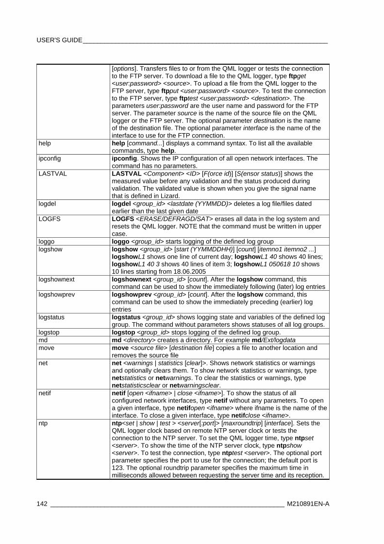
USER'S GUIDE____________________________________________________________________
142 _________________________________________________________________ M210891EN-A
[options]. Transfers files to or from the QML logger or tests the connection to the FTP server. To download a file to the QML logger, type ftpget <user:password> <source>. To upload a file from the QML logger to the FTP server, type ftpput <user:password> <source>. To test the connection to the FTP server, type ftptest <user:password> <destination>. The parameters user:password are the user name and password for the FTP server. The parameter source is the name of the source file on the QML logger or the FTP server. The optional parameter destination is the name of the destination file. The optional parameter interface is the name of the interface to use for the FTP connection.
help help [command...] displays a command syntax. To list all the available commands, type help.
ipconfig ipconfig. Shows the IP configuration of all open network interfaces. The command has no parameters.
LASTVAL LASTVAL <Component> <ID> [F(orce id)] [S(ensor status)] shows the measured value before any validation and the status produced during validation. The validated value is shown when you give the signal name that is defined in Lizard.
logdel logdel <group_id> <lastdate (YYMMDD)> deletes a log file/files dated earlier than the last given date
LOGFS LOGFS <ERASE/DEFRAGD/SAT> erases all data in the log system and resets the QML logger. NOTE that the command must be written in upper case.
loggo loggo <group_id> starts logging of the defined log group logshow logshow <group_id> [start (YYMMDDHH)] [count] [itemno1 itemno2 ...]
logshowL1 shows one line of current day; logshowL1 40 shows 40 lines; logshowL1 40 3 shows 40 lines of item 3; logshowL1 050618 10 shows 10 lines starting from 18.06.2005
logshownext logshownext <group_id> [count]. After the logshow command, this command can be used to show the immediately following (later) log entries
logshowprev logshowprev <group_id> [count]. After the logshow command, this command can be used to show the immediately preceding (earlier) log entries
logstatus logstatus <group_id> shows logging state and variables of the defined log group. The command without parameters shows statuses of all log groups.
logstop logstop <group_id> stops logging of the defined log group. md md <directory> creates a directory. For example md/Ext/logdata move move <source file> [destination file] copies a file to another location and
removes the source file net net <warnings | statistics [clear]>. Shows network statistics or warnings
and optionally clears them. To show network statistics or warnings, type netstatistics or netwarnings. To clear the statistics or warnings, type netstatisticsclear or netwarningsclear.
netif netif [open <ifname> | close <ifname>]. To show the status of all configured network interfaces, type netif without any parameters. To open a given interface, type netifopen <ifname> where ifname is the name of the interface. To close a given interface, type netifclose <ifname>.
ntp ntp<set | show | test > <server[:port]> [maxroundtrip] [interface]. Sets the QML logger clock based on remote NTP server clock or tests the connection to the NTP server. To set the QML logger time, type ntpset <server>. To show the time of the NTP server clock, type ntpshow <server>. To test the connection, type ntptest <server>. The optional port parameter specifies the port to use for the connection; the default port is 123. The optional roundtrip parameter specifies the maximum time in milliseconds allowed between requesting the server time and its reception.
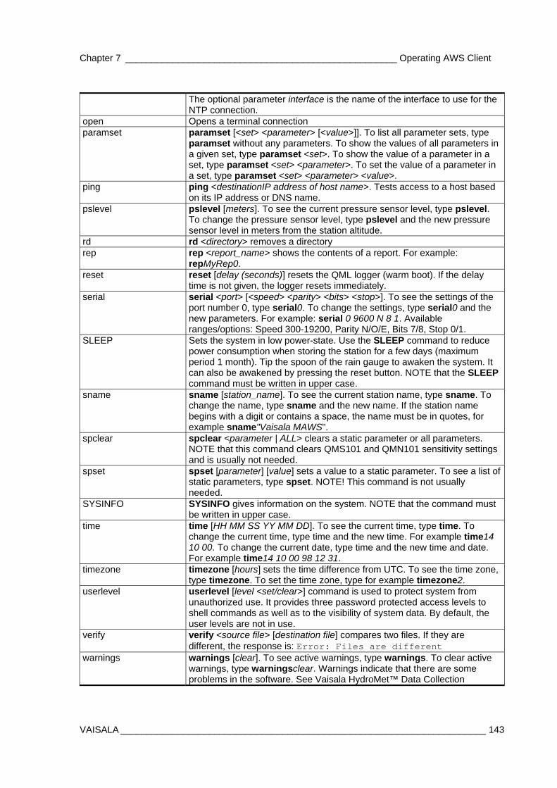
Chapter 7 ____________________________________________________ Operating AWS Client
VAISALA ______________________________________________________________________ 143
The optional parameter interface is the name of the interface to use for the NTP connection.
open Opens a terminal connection paramset paramset [<set> <parameter> [<value>]]. To list all parameter sets, type
paramset without any parameters. To show the values of all parameters in a given set, type paramset <set>. To show the value of a parameter in a set, type paramset <set> <parameter>. To set the value of a parameter in a set, type paramset <set> <parameter> <value>.
ping ping <destinationIP address of host name>. Tests access to a host based on its IP address or DNS name.
pslevel pslevel [meters]. To see the current pressure sensor level, type pslevel. To change the pressure sensor level, type pslevel and the new pressure sensor level in meters from the station altitude.
rd rd <directory> removes a directory rep rep <report_name> shows the contents of a report. For example:
repMyRep0. reset reset [delay (seconds)] resets the QML logger (warm boot). If the delay
time is not given, the logger resets immediately. serial serial <port> [<speed> <parity> <bits> <stop>]. To see the settings of the
port number 0, type serial0. To change the settings, type serial0 and the new parameters. For example: serial 0 9600 N 8 1. Available ranges/options: Speed 300-19200, Parity N/O/E, Bits 7/8, Stop 0/1.
SLEEP Sets the system in low power-state. Use the SLEEP command to reduce power consumption when storing the station for a few days (maximum period 1 month). Tip the spoon of the rain gauge to awaken the system. It can also be awakened by pressing the reset button. NOTE that the SLEEP command must be written in upper case.
sname sname [station_name]. To see the current station name, type sname. To change the name, type sname and the new name. If the station name begins with a digit or contains a space, the name must be in quotes, for example sname"Vaisala MAWS".
spclear spclear <parameter | ALL> clears a static parameter or all parameters. NOTE that this command clears QMS101 and QMN101 sensitivity settings and is usually not needed.
spset spset [parameter] [value] sets a value to a static parameter. To see a list of static parameters, type spset. NOTE! This command is not usually needed.
SYSINFO SYSINFO gives information on the system. NOTE that the command must be written in upper case.
time time [HH MM SS YY MM DD]. To see the current time, type time. To change the current time, type time and the new time. For example time14 10 00. To change the current date, type time and the new time and date. For example time14 10 00 98 12 31.
timezone timezone [hours] sets the time difference from UTC. To see the time zone, type timezone. To set the time zone, type for example timezone2.
userlevel userlevel [level <set/clear>] command is used to protect system from unauthorized use. It provides three password protected access levels to shell commands as well as to the visibility of system data. By default, the user levels are not in use.
verify verify <source file> [destination file] compares two files. If they are different, the response is: Error: Files are different
warnings warnings [clear]. To see active warnings, type warnings. To clear active warnings, type warningsclear. Warnings indicate that there are some problems in the software. See Vaisala HydroMet™ Data Collection
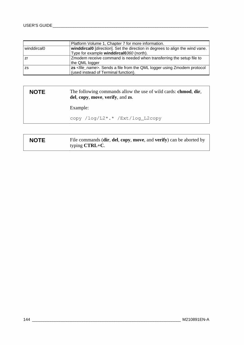
USER'S GUIDE____________________________________________________________________
144 _________________________________________________________________ M210891EN-A
Platform Volume 1, Chapter 7 for more information. winddircal0 winddircal0 [direction]. Set the direction in degrees to align the wind vane.
Type for example winddircal0360 (north). zr Zmodem receive command is needed when transferring the setup file to
the QML logger zs zs <file_name>. Sends a file from the QML logger using Zmodem protocol
(used instead of Terminal function).
NOTE The following commands allow the use of wild cards: chmod, dir, del, copy, move, verify, and zs.
Example:
copy /log/L2*.* /Ext/log_L2copy
NOTE File commands (dir, del, copy, move, and verify) can be aborted by typing CTRL+C.
Chapter 8 ______________________________________________ WD50 Wind Display Operation
VAISALA ______________________________________________________________________ 145
CHAPTER 8
WD50 WIND DISPLAY OPERATION
This chapter provides information on using the WD50 Wind Display.
User Interface WIND 50 is an advanced wind display for professional use, especially designed for demanding aviation applications. It is suitable for simple point-to-point use at small airports, but has enough functions to be used at the largest installations.
The user interface is easy to read in any light conditions. Brightness is automatically adjusted according to the ambient light conditions. All the static display elements are backlit for nighttime operation.
A rotary switch and two push buttons serve for switching between different display pages, setting alarms and testing the unit.
The different display elements are illustrated in Figure 73 on page 146.

USER'S GUIDE____________________________________________________________________
146 _________________________________________________________________ M210891EN-A
1 2
3
4
5
678
9
10
Figure 73 WD50 Display Elements
The following figures refer to Figure 75 on page 155:
1 = Max wind 2 = Min wind 3 = Units 4 = Alarm select 5 = Ext/cross set 6 = Page select 7 = Speed 8 = Page text 9 = Direction variance 10 = Direction
One rotary switch and two 3-state push buttons are for manual control. The rotary switch is for selecting between different display pages and the push buttons are used for switching between extreme/crosswind calculations and for mastering the alarms.
The instant, 2-minute, and 10-minute wind speeds are presented with three digits using decimal or integer presentations.
Chapter 8 ______________________________________________ WD50 Wind Display Operation
VAISALA ______________________________________________________________________ 147
The extremes (wind speed minimum and maximum) as well as cross- and tailwind components are shown at the upper corners with digital elements.
The wind direction is shown using analog and digital presentations. The 36 LEDs provide a resolution of 10 degrees for the analog indicator. However, the digital presentation supports different resolutions from decimal to 10 degrees. Wind direction variation is presented with an analog LED circle.
All the static indicators, such as different wind speed units, are backlit.
The text shown on the 16 character alphanumeric dot matrix field, locating at the bottom of the display page, is user definable for each of the display pages in use.
Display Pages The content of the display page is formed from received data, and presented on a display after data processing (e.g. calculating average) and defined presenting rules (page specific).
The rotary switch is for selecting between different display pages. Turn the rotary switch clockwise to increase the page number. After the last defined page, follows the first page again. Turn the rotary switch counterclockwise to decrease the page number.
Even though the number of pages is user configurable, there are always a display test page and a manual brightness control page.
Page 1 is showing Relative wind instant values.
Page 2 is showing Relative wind two minutes average values.
Page 3 is showing Relative wind ten minutes average values.
Page 4 is showing True wind instant values.
Page 5 is showing True wind two minutes average values.
Page 6 is showing True wind tem minutes average values.
Page 7 is showing Relative wind port side sensors two minutes average values.
Page 8 is showing Relative wind starboard side sensors two minutes average values.
USER'S GUIDE____________________________________________________________________
148 _________________________________________________________________ M210891EN-A
Page 9 is showing True wind port side sensors two minutes average values.
Page 10 is showing True wind starboard side sensors two minutes average values.
Brightness Control The brightness of the display is normally automatically adjusted. However, base level brightness can be manually changed using the brightness page as follows:
1. Select brightness page.
2. Press the SET button to middle position and keep it pressed to increase the brightness. Press the SET button to bottom position and keep it pressed to decrease the brightness level.
NOTE The % value of the maximum brightness display will change according to the ambient light conditions.
Test Page When the test page is selected, some basic information such as software version, supply voltage and internal temperature of the unit are displayed on the page text display.
If the internal temperature rises above defined limit, the fan will be switched on to cool the unit.
Display Reset The display can be reset in one of the following ways:
1. Power down/up the unit.
2. At the test page, press the ALR button to the bottom position and keep it pressed for 5 seconds.
3. Send reset command via serial interface (and accept by entering y).
NOTE The display must be reset to enable new configuration.

Chapter 9 __________________________________________________ DD50 Display Operation
VAISALA ______________________________________________________________________ 149
CHAPTER 9
DD50 DISPLAY OPERATION
This chapter provides information on using the DD50 display.
Introduction The DD50 is universal digital display that can be directly connected to Vaisala’s intelligent sensors to build small systems or it can be used as a general purpose display. The software of the DD50 is implemented as several independent products, called display modes. The system configuration can contain several setups at the same time, so that one DD50 device can serve as a spare part for different types of systems. Only the display mode is changed in a spare unit, when a failed unit is replaced with a pre-configured DD50.
The main source of information to the DD50 display is the serial line.
The operation of the DD50 is described as a single mode system would be used. Configuration and operation procedures are common to all modes or otherwise general.
Critical system parameters can only be set through the serial line (some are password protected) but many of them can be set and displayed using the front panel switch/button operations.
There are also four general purpose 10-bit analog inputs that are used in some display modes. The DD50 has a battery backed-up clock to keep the data recordings in time.
In normal operation the user only selects the display “page” using the rotary switch.
The data values are presented numerically with three bright 5-digit 7-segment fields. The type of the data values is indicated with a 4-
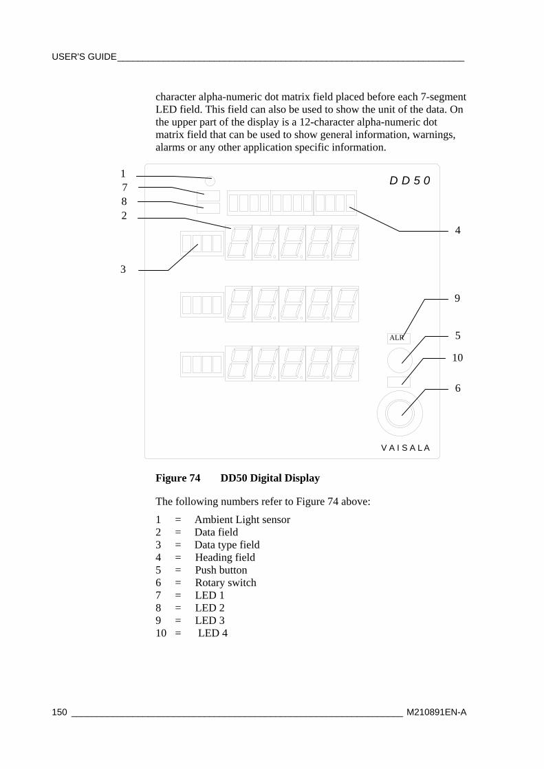
USER'S GUIDE____________________________________________________________________
150 _________________________________________________________________ M210891EN-A
character alpha-numeric dot matrix field placed before each 7-segment LED field. This field can also be used to show the unit of the data. On the upper part of the display is a 12-character alpha-numeric dot matrix field that can be used to show general information, warnings, alarms or any other application specific information.
D D 5 0
V A IS A L A
Figure 74 DD50 Digital Display
The following numbers refer to Figure 74 above:
1 = Ambient Light sensor 2 = Data field 3 = Data type field 4 = Heading field 5 = Push button 6 = Rotary switch 7 = LED 1 8 = LED 2 9 = LED 3 10 = LED 4
2
3
5
6
4
1 7 8
9
10
ALR

Chapter 9 ___________________________________________________ DD50 Display Operation
VAISALA ______________________________________________________________________ 151
A double-action push button is provided for inquiring the data units, for acknowledgement of alarm and for resetting the display. It is also used together with the rotary switch for display configuration.
A rotary switch is provided for changing the display page and for display configuration.
There is an LDR (Light Dependent Resistor) monitoring the ambient lighting conditions. The brightness of the display LEDs is automatically controlled based on the LDR readings.
Display Pages The content of the display page is formed from received data, and presented on a display.
The rotary switch is for selecting between different display pages. Turn the rotary switch clockwise to increase the page number. After the last defined page, follows the first page again. Turn the rotary switch counterclockwise to decrease the page number.
The following presents a typical configuration of the pages.
Page 1: Heading TEMP data
TT1: is showing air temperature, one minute average. Unit is degrees celsius (shows when pressing the push button)
TW1: is showing water temperature, one minute average. Unit is degrees celsius (shows when pressing the push button)
TD1: is showing dew point temperature, one minute average. Unit is degrees celsius (shows when pressing the push button)
Page 2: Heading Pressure
P: is showing air pressure, one minute average. Unit is hPa (shows when pressing the push button)
QNH: is showing QNH pressure, one minute average. Unit is hPa (shows when pressing the push button)
QFE: is showing QFE pressure, one minute average. Unit is hPa (shows when pressing the push button)
Page 3: Heading Vis/Clouds
USER'S GUIDE____________________________________________________________________
152 _________________________________________________________________ M210891EN-A
MOR: is showing visibility value, one minute average. Unit is km (kilometers, shows when pressing the push button)
H1: is showing first cloud layer. Unit is feet (shows when pressing the push button)
RH: is showing relative humidity, one minute average. Unit is % (shows when pressing the push button)
Page 4: Heading Wind/Ship
FG: is showing wind gust, ten minutes maximum wind. Unit is knots (shows when pressing the push button)
Sspd: is showing ship's speed from LOG. Unit is knots (shows when pressing the push button)
Sdir: is showing ship's heading from Gyro. Unit is degrees (shows when pressing the push button)
Chapter 10 ___________________________________________________________ Maintenance
VAISALA ______________________________________________________________________ 153
CHAPTER 10
MAINTENANCE
This chapter provides information that is needed in basic maintenance of the product.
Cleaning and Overall Checking Check the mechanics and cabling for any damage and corrosion, and repair if needed:
- Inspect cables for breaks, cracks in the protective coating or cable connectors, and bent, damaged, or misaligned pins.
- Also wipe off or remove excess dirt, dust, sand, or leaves.
- Check signal and main cables, grounding cables, lugs, connectors, and connections.
- Also check gaskets of the enclosures and mechanical assemblies, bolts, nuts, etc.
Checking Enclosure Every six months, check visually that the box internal wiring is in order.
NOTE After a heavy storm, open the enclosure door and check for any water leakage or other damage.
USER'S GUIDE____________________________________________________________________
154 _________________________________________________________________ M210891EN-A
Mast Maintenance The mast is coated for durability in demanding harsh environments. Normally there is no need for maintenance. Check the mast yearly for any damage to the coating.
However, when devices installed on the upper assembly need maintenance, you need to tilt the mast:
Tilting the Mast You need to tilt the mast, for example, when devices installed on the upper assembly need maintenance.
To tilt a mast that is equipped with the tilt division flange, follow the procedure below:
CAUTION Do not open the Allen bolts in the horizontal hinge axle (number 5 in Figure 75 on page 155.
CAUTION Make sure that there is enough clear area on the tilting side of the mast. The area should be free of obstacles preventing the mast from being tilted.
1. Open the nuts (number 3 in Figure 75 on page 155) and remove them and the washers (4). Do not open the other nuts (6 and 7).
2. Make sure to have a good control of the mast (1), and lower the mast slowly.
3. Support the mast with a suitable support and do not let it lean on the wind sensor, or other sensors.
CAUTION Do not let the mast lean on the sensors, use a suitable support instead.

Chapter 10 ___________________________________________________________ Maintenance
VAISALA ______________________________________________________________________ 155
0308-057
Figure 75 Tilting the Short Pole Mast
To erect the mast after maintenance operations, follow the procedure below:
1. Lift the mast vertical.
2. To secure the mast, install the nuts (number 3 in Figure 75 above).
3. Finally, tighten the nuts with the appropriate wrenches.
Wind Sensor Maintenance
Cleaning At least once a year, clean the sensor from dust and dirt using mild washing detergent and a micro-fibre towel.
CAUTION Be gentle when cleaning the transducers as they are very fragile. Do not scrape, rotate, pull, strike, or bend the transducers.
CAUTION Do not use alcohol-based cleaning agents.
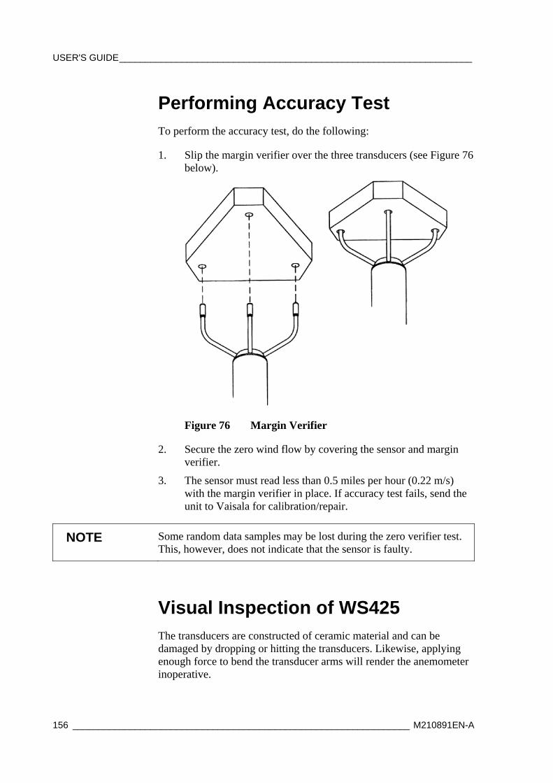
USER'S GUIDE____________________________________________________________________
156 _________________________________________________________________ M210891EN-A
Performing Accuracy Test To perform the accuracy test, do the following:
1. Slip the margin verifier over the three transducers (see Figure 76 below).
Figure 76 Margin Verifier
2. Secure the zero wind flow by covering the sensor and margin verifier.
3. The sensor must read less than 0.5 miles per hour (0.22 m/s) with the margin verifier in place. If accuracy test fails, send the unit to Vaisala for calibration/repair.
NOTE Some random data samples may be lost during the zero verifier test. This, however, does not indicate that the sensor is faulty.
Visual Inspection of WS425 The transducers are constructed of ceramic material and can be damaged by dropping or hitting the transducers. Likewise, applying enough force to bend the transducer arms will render the anemometer inoperative.
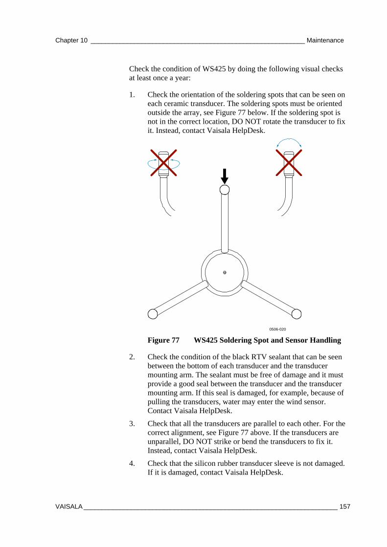
Chapter 10 ___________________________________________________________ Maintenance
VAISALA ______________________________________________________________________ 157
Check the condition of WS425 by doing the following visual checks at least once a year:
1. Check the orientation of the soldering spots that can be seen on each ceramic transducer. The soldering spots must be oriented outside the array, see Figure 77 below. If the soldering spot is not in the correct location, DO NOT rotate the transducer to fix it. Instead, contact Vaisala HelpDesk.
0506-020
Figure 77 WS425 Soldering Spot and Sensor Handling
2. Check the condition of the black RTV sealant that can be seen between the bottom of each transducer and the transducer mounting arm. The sealant must be free of damage and it must provide a good seal between the transducer and the transducer mounting arm. If this seal is damaged, for example, because of pulling the transducers, water may enter the wind sensor. Contact Vaisala HelpDesk.
3. Check that all the transducers are parallel to each other. For the correct alignment, see Figure 77 above. If the transducers are unparallel, DO NOT strike or bend the transducers to fix it. Instead, contact Vaisala HelpDesk.
4. Check that the silicon rubber transducer sleeve is not damaged. If it is damaged, contact Vaisala HelpDesk.
USER'S GUIDE____________________________________________________________________
158 _________________________________________________________________ M210891EN-A
Compass and GPS Maintenance The compass and GPS are maintenance-free, in case of malfunction replace the sensor with a new one.
QMH102 Temperature & Humidity Sensor Maintenance
Visual Check
Every 3 months, check that the temperature & humidity probe mounting is secure and that the cable is in good condition.
Changing Temperature/Humidity Membrane Filter Every 6 months, change the temperature/humidity membrane filter:
1. Remove the sensor from inside the radiation shield.
2. Carefully remove the filter: screw it anticlockwise, then carefully pull it out without touching the measurement heads.
3. Install without delay the new filter carefully without touching the measurement head.
Sending for Calibration Once a year, the humidity sensor part of the QMH102 probe requires calibration. Send it to Vaisala for calibration and replace it with a calibrated probe:
1. Remove the sensor from inside the radiation shield.
2. Remove the probe head from the probe body and replace it with a calibrated spare part (probe head).
3. Check the operation of the new probe by warming the sensor head with your hand, and monitor the value change.
4. Place the sensor back inside the radiation shield.
Or, if a calibrated spare part is not available, do the following:

Chapter 10 ___________________________________________________________ Maintenance
VAISALA ______________________________________________________________________ 159
1. Send the old probe head to Vaisala for calibration.
2. When the calibrated probe head arrives from Vaisala, insert the calibrated probe head to the probe body.
3. Check the operation of the new probe by warming the sensor head with your hand, and monitor the value change.
Inside Enclosure Maintenance
Checking Battery Battery status should be checked every 3 months. This is done either using a multi-meter on the batteries plus and minus, or by pressing the QBR101 battery charger. Press the QBR101C Battery charger status button to see the battery status and if the system has any power (Mains/battery):
- If the LED is green, the battery is ok.
- If the LED is yellow, the battery voltage is low (charge<11.5V).
- If the LED is red, the battery is empty (charge<10V).
If the battery status is red even after charging for a while, the battery is old and needs to be replaced. The lead acid battery may age in 3 to 5 years and needs to be replaced with a new one.
Calibrating PMT16A Pressure Sensor Keep the pressure port clean. Check the pressure port and hose every time when visiting the site.
Annually, compare pressure values against a calibrated portable standard and if needed, make adjustments or send the sensor for calibration to Vaisala.
1. Place the calibrated reference sensor at the same level with PMT16A.
2. Compare the reading with the reference reading:
- If the difference is less than ±0.3hPa, no adjustment is needed.
USER'S GUIDE____________________________________________________________________
160 _________________________________________________________________ M210891EN-A
- If the difference is more than ±0.8hPa, send the sensor to Vaisala for calibration, see section Changing PMT16A Pressure Sensor on page 163.
- If the difference is between ±0.3hPa and ±0.8hPa, do the following:
3. Establish terminal connection to MAWS logger by connecting the maintenance cable to the COM0 port of the enclosure and to an available I/O port on your PC.
4. Type open to get to service connection.
5. Read the reference sensor reading and type PMT16CAL <pressure reading from reference sensor>. For example, PMT16CAL 1001.80
6. Now the sensor is being calibrated.
7. Check the readings given by MAWS against the reference value and repeat the calibration if necessary.
8. Close the terminal connection by giving the close command.
Changing Components In some over voltage conditions e.g in case of lightning strike some protective components might get damaged and need replacement. In these cases the surge arrestors are the most sensitive parts of the system and might need replacement. See section Replacing Consumables.
Replacing Consumables This section describes how to replace consumables.
Changing Battery 1. Turn the power off from the main switch.
2. Unplug the battery wires.
3. Unscrew the screw holding the battery clamp around the battery.
4. Slide the clamp to the left.

Chapter 10 ___________________________________________________________ Maintenance
VAISALA ______________________________________________________________________ 161
5. Remove the battery.
6. Install a new battery in the opposite order.
Changing the QML201 Logger 1. Turn the power off from the main switch.
2. Unplug the logger connectors.
3. Remove the wires from the plastic cable holders and from the cable ties in the logger installation plate.
4. Remove the logger installation plate from the frame with the logger connected to it.
5. Install a new logger and installation plate and in the opposite order.
Changing the Power Supply Set 1. Turn off the mains power to MAWS, e.g. switch off the external
AC (mains) inlet.
2. Unscrew the left-hand side installation plate and flip it down.
3. If your system contains the satellite transmitter, disconnect the satellite transmitter wires from the terminal strip. See wiring diagram Appendix C Wiring Diagrams on page 217.
CAUTION Do not leave the satellite transmitter hanging from the wires; remove it with the installation plate.
4. Unscrew evenly the 4 screws holding the right-hand installation plate and remove the installation plate (and when applicable, the satellite transmitter connected to it) from the frame.
5. Remove the power supply set connectors and cut the cable ties on top of the power supply set.
6. Unscrew the four bolts in the power supply set indicated with arrows in Figure 78 on page 162.
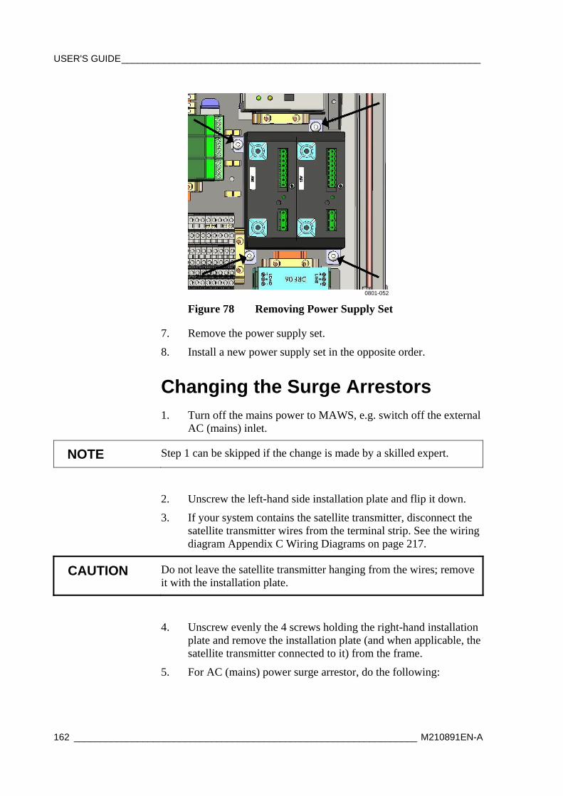
USER'S GUIDE____________________________________________________________________
162 _________________________________________________________________ M210891EN-A
0801-052
Figure 78 Removing Power Supply Set
7. Remove the power supply set.
8. Install a new power supply set in the opposite order.
Changing the Surge Arrestors 1. Turn off the mains power to MAWS, e.g. switch off the external
AC (mains) inlet.
NOTE Step 1 can be skipped if the change is made by a skilled expert.
2. Unscrew the left-hand side installation plate and flip it down.
3. If your system contains the satellite transmitter, disconnect the satellite transmitter wires from the terminal strip. See the wiring diagram Appendix C Wiring Diagrams on page 217.
CAUTION Do not leave the satellite transmitter hanging from the wires; remove it with the installation plate.
4. Unscrew evenly the 4 screws holding the right-hand installation plate and remove the installation plate (and when applicable, the satellite transmitter connected to it) from the frame.
5. For AC (mains) power surge arrestor, do the following:

Chapter 10 ___________________________________________________________ Maintenance
VAISALA ______________________________________________________________________ 163
- If the indicator on the top of the surge arrester plug is red, (see Figure 12 on page 28) remove the plug module, indicated with an arrow in Figure 79 below, and replace the plug with a new one.
0801-048
Figure 79 Removing Mains Power Surge Plug
6. For QSA224DC (data line) surge, do the following:
- Disconnect the wires from the faulty surge arrestor and remove the surge.
- Install a new surge arrestor in the opposite order.
Changing PMT16A Pressure Sensor If the PMT16A pressure sensor needs to be replaced, do the following:
1. Remove the QML201 cover.
2. Unscrew the screw holding PMT16A.
3. Unplug the pressure hose that connects PMT16A to the logger body.
4. Remove the PMT16A pressure sensor from the logger using a suitable flat-bladed screw driver to unlock the plastic clip, see Figure 80 on page 164 and Figure 81 on page 164.

USER'S GUIDE____________________________________________________________________
164 _________________________________________________________________ M210891EN-A
0801-053
Figure 80 Removing PMT16A
0801-048
Figure 81 Removing PMT16A
5. Install a new pressure sensor in the opposite order.
DTS12W Water Temperature Sensor Maintenance
Every year check that the water temperature sensor mounting is secure and that the cable is in good condition. The sensor does not need any calibration.
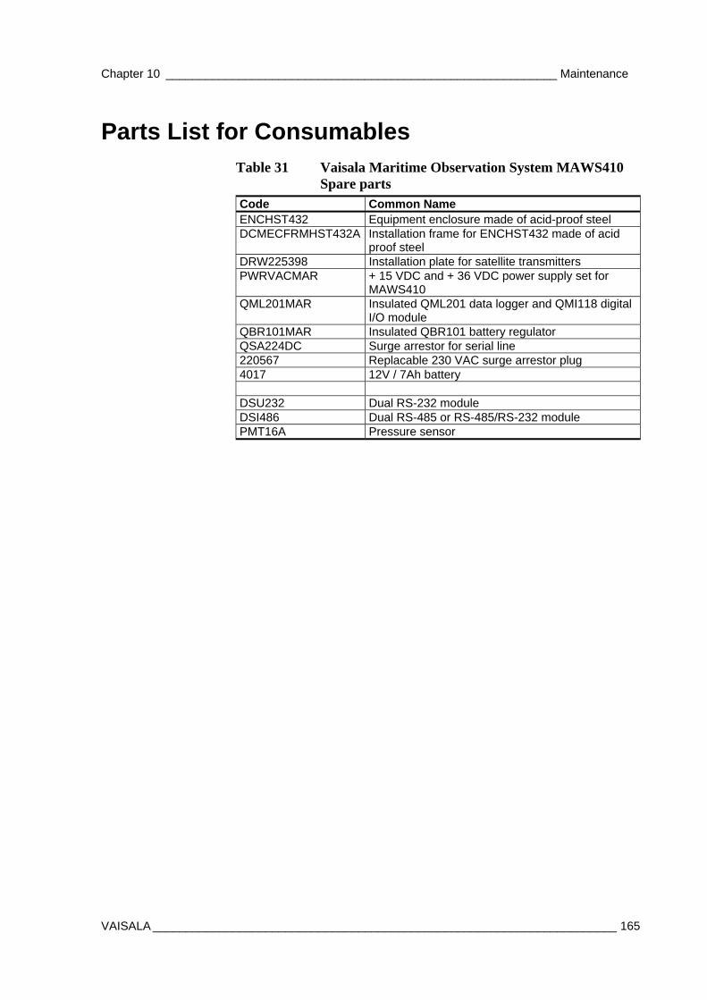
Chapter 10 ___________________________________________________________ Maintenance
VAISALA ______________________________________________________________________ 165
Parts List for Consumables Table 31 Vaisala Maritime Observation System MAWS410
Spare parts Code Common Name ENCHST432 Equipment enclosure made of acid-proof steel DCMECFRMHST432A Installation frame for ENCHST432 made of acid
proof steel DRW225398 Installation plate for satellite transmitters PWRVACMAR + 15 VDC and + 36 VDC power supply set for
MAWS410 QML201MAR Insulated QML201 data logger and QMI118 digital
I/O module QBR101MAR Insulated QBR101 battery regulator QSA224DC Surge arrestor for serial line 220567 Replacable 230 VAC surge arrestor plug 4017 12V / 7Ah battery DSU232 Dual RS-232 module DSI486 Dual RS-485 or RS-485/RS-232 module PMT16A Pressure sensor

USER'S GUIDE____________________________________________________________________
166 _________________________________________________________________ M210891EN-A
This page intentionally left blank.
Chapter 11 _______________________________________________________ Troubleshooting
VAISALA ______________________________________________________________________ 167
CHAPTER 11
TROUBLESHOOTING
This chapter describes common problems, their probable causes and remedies, and contact information for technical support.
Display Software and Digital Displays The first step in troubleshooting the system is to check if the Maritime Observation Console software and/or the optional DD50 and WD50 displays are getting any data from the data logger:
- If only one sensor data disappears or shows slashes, you can assume that there is a problem with the sensor or with its cabling to the equipment enclosure.
- If the latitude information is missing, you can assume that the MAWS410 is not getting any GPS readings.
- If the ship heading and true wind is missing, MAWS410 is not getting any compass readings.
- If only one display stops working, you can assume that the display is either broken or has a communication line failure with MAWS410. Check incoming messages with the terminal software. If the message is coming in normally, check display wiring and try resetting the display.
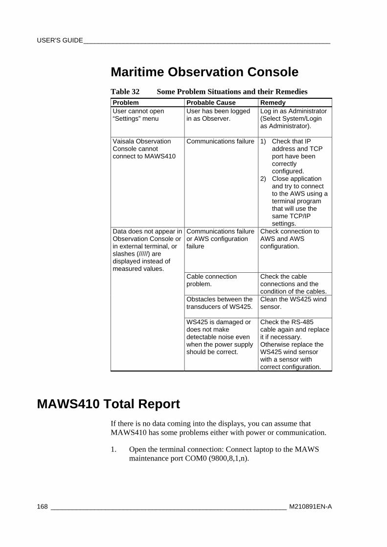
USER'S GUIDE____________________________________________________________________
168 _________________________________________________________________ M210891EN-A
Maritime Observation Console Table 32 Some Problem Situations and their Remedies Problem Probable Cause Remedy User cannot open “Settings” menu
User has been logged in as Observer.
Log in as Administrator (Select System/Login as Administrator).
Vaisala Observation Console cannot connect to MAWS410
Communications failure 1) Check that IP address and TCP port have been correctly configured.
2) Close application and try to connect to the AWS using a terminal program that will use the same TCP/IP settings.
Data does not appear in Observation Console or in external terminal, or slashes (/////) are displayed instead of measured values.
Communications failure or AWS configuration failure
Check connection to AWS and AWS configuration.
Cable connection problem.
Check the cable connections and the condition of the cables.
Obstacles between the transducers of WS425.
Clean the WS425 wind sensor.
WS425 is damaged or does not make detectable noise even when the power supply should be correct.
Check the RS-485 cable again and replace it if necessary. Otherwise replace the WS425 wind sensor with a sensor with correct configuration.
MAWS410 Total Report If there is no data coming into the displays, you can assume that MAWS410 has some problems either with power or communication.
1. Open the terminal connection: Connect laptop to the MAWS maintenance port COM0 (9800,8,1,n).
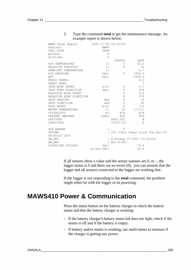
Chapter 11 _______________________________________________________ Troubleshooting
VAISALA ______________________________________________________________________ 169
2. Type the command total to get the maintenance message. An example report is shown below:
MAWS Total Report 2007-11-28 12:36:04 Station: MAWS CALL SIGN OHVA pslevel 0 altitude 0 STATUS INST AIR TEMPERATURE C: 0 22.3 RELATIVE HUMIDITY %: 0 16 DEWPOINT TEMPERATURE C: -4.7 AIR PRESSURE hPa: 0 1004.3 QFF hPa: 1004.3 PRESS TREND: -0.3 PRESS TEND: 7 TRUE WIND SPEED m/s: 0 2.7 TRUE WIND DIRECTION deg: 0 204 RELATIVE WIND SPEED 0 0.0 RELATIVE WIND DIRECTION 0 270 SHIP HEADING deg 0 16 SHIP DIRECTION deg 0 24 SHIP SPEED m/s: 0 3.0 WATER TEMPERATURE C: 23 ////// VISIBILITY m: N/A N/A PRESENT WEATHER code: N/A N/A LATITUDE 6001.222 N LONGITUDE 11523.121 E SYS ERRORS : 0 UPTIME : 27h 27min 29sec since Tue Nov 27 09:08:35 2007 SW_REV : 6.00(Sep 19 2007 11:18:09) HW_REV : Rev B-001 OPERATING VOLTAGE Vdc: 15.4 1h min Vdc: 15.4
If all sensors show a value and the sensor statuses are 0, or –, the logger status is 0 and there are no errors (0), you can assume that the logger and all sensors connected to the logger are working fine.
If the logger is not responding to the total command, the problem might either be with the logger or its powering.
MAWS410 Power & Communication Press the status button on the battery charger to check the battery status and that the battery charger is working:
- If the battery charger's battery status led does not light, check if the mains is off and if the battery is empty.
- If battery and/or mains is working, use multi-meter to measure if the charger is getting any power.
USER'S GUIDE____________________________________________________________________
170 _________________________________________________________________ M210891EN-A
- If the charger is getting power and still does not work, the charger is broken and needs to be replaced. See section Replacing Consumables on page 160.
If mains power from the ship is on, check that all power supplies have the green led on:
- If the green led does not light, check with multi-meter that the power supply is getting AC power.
- If the power supply is getting power and the green led is not on, the power supply or at least its led is not working and has to be replaced. See section Replacing Consumables on page 160.
Check that the green led on QML201 data logger is blinking once in a while:
- If the green led is not blinking and there is no data coming to the displays, the logger might be damaged, or does not get power. Check with multi-meter if the logger is getting power.
If the logger is getting power, try establishing a service connection via COM0 and maintenance cable.
- Set the terminal settings to 9600, 8, 1, n and type the command open. If the logger answers with service connection, the logger is working.
- Type the command errors, to check the error messages from the logger. If error messages occur, the logger, the logger configuration, or one of the communication modules might be broken.
- Type the command warnings to get the warning messages from the logger. Warning messages are not usually serious but useful for troubleshooting.
- Type the command SYSINFO to get system uptime information.
- Type the command reset to reset the logger.
- Type the command total to get the maintenance message.
- Close service connection by typing close.
Chapter 11 _______________________________________________________ Troubleshooting
VAISALA ______________________________________________________________________ 171
Problem Report When troubleshooting the product, write a problem report consisting of the following issues:
- What failed (what worked / did not work)?
- Where did it fail (location and environment)?
- When did it fail (date, immediately / after a while / periodically / randomly)?
- How many failed (only one defect / other same or similar defects / several failures in one unit)?
- What was connected to the product and to which connectors?
- Input power source type, voltage and list of other items (lighting, heaters, motors etc.) that were connected to the same power output.
- What was done when the failure was noticed?
Request an RMA from Vaisala helpdesk, see section Requesting RMA below.
Requesting RMA If the product needs repair, please follow the instructions below to speed up the process and to avoid extra costs to you.
1. Read the warranty information.
2. Contact Vaisala technical support via e-mail or fax and request for RMA (Return Material Authorization) and shipping instructions.
3. Proceed as instructed by Vaisala technical support, see section Technical Support on page 172.
NOTE RMA must always be requested from Vaisala technical support before returning any faulty material.

USER'S GUIDE____________________________________________________________________
172 _________________________________________________________________ M210891EN-A
Technical Support For technical questions, contact the Vaisala technical support:
E-mail [email protected]
Fax +358 9 8949 2790
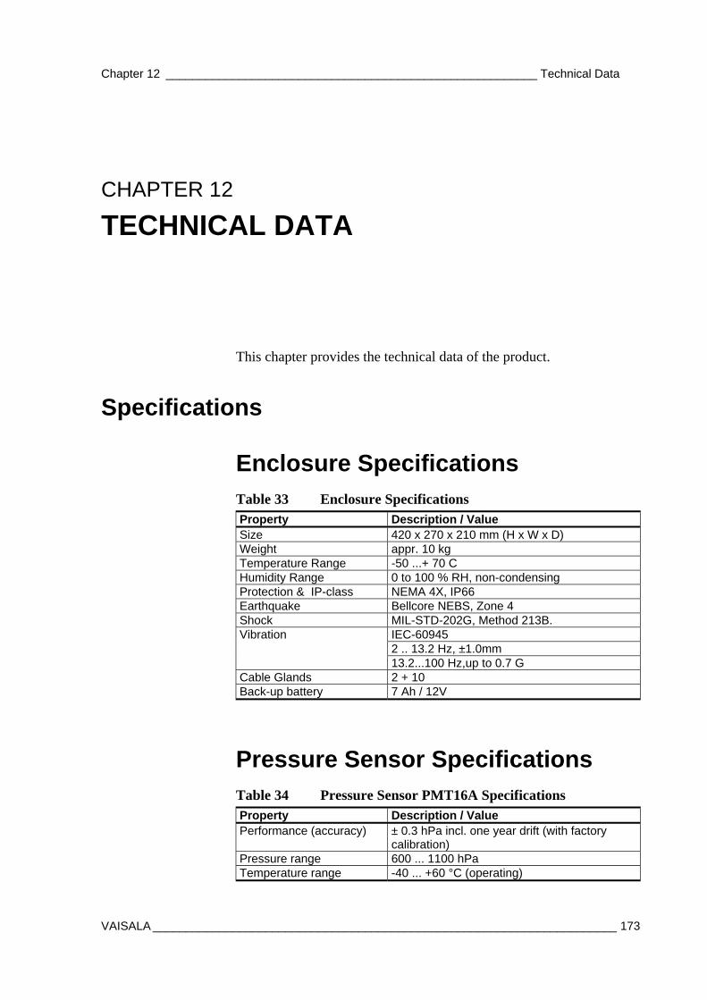
Chapter 12 ________________________________________________________ Technical Data
VAISALA ______________________________________________________________________ 173
CHAPTER 12
TECHNICAL DATA
This chapter provides the technical data of the product.
Specifications
Enclosure Specifications
Table 33 Enclosure Specifications Property Description / Value Size 420 x 270 x 210 mm (H x W x D) Weight appr. 10 kg Temperature Range -50 ...+ 70 C Humidity Range 0 to 100 % RH, non-condensing Protection & IP-class NEMA 4X, IP66 Earthquake Bellcore NEBS, Zone 4 Shock MIL-STD-202G, Method 213B. Vibration IEC-60945 2 .. 13.2 Hz, ±1.0mm 13.2...100 Hz,up to 0.7 G Cable Glands 2 + 10 Back-up battery 7 Ah / 12V
Pressure Sensor Specifications Table 34 Pressure Sensor PMT16A Specifications Property Description / Value Performance (accuracy) ± 0.3 hPa incl. one year drift (with factory
calibration) Pressure range 600 ... 1100 hPa Temperature range -40 ... +60 °C (operating)
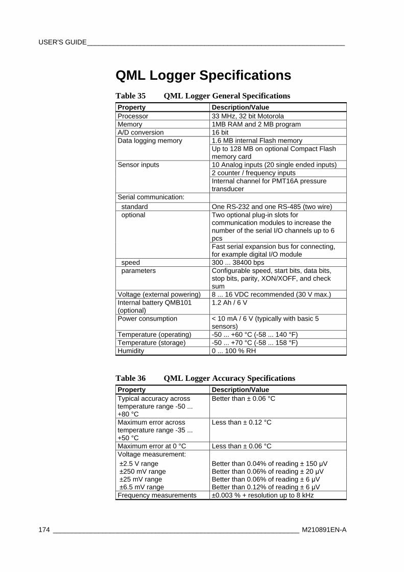
USER'S GUIDE____________________________________________________________________
174 _________________________________________________________________ M210891EN-A
QML Logger Specifications Table 35 QML Logger General Specifications Property Description/Value Processor 33 MHz, 32 bit Motorola Memory 1MB RAM and 2 MB program A/D conversion 16 bit Data logging memory 1.6 MB internal Flash memory Up to 128 MB on optional Compact Flash
memory card Sensor inputs 10 Analog inputs (20 single ended inputs) 2 counter / frequency inputs Internal channel for PMT16A pressure
transducer Serial communication: standard One RS-232 and one RS-485 (two wire) optional Two optional plug-in slots for
communication modules to increase the number of the serial I/O channels up to 6 pcs
Fast serial expansion bus for connecting, for example digital I/O module
speed 300 ... 38400 bps parameters Configurable speed, start bits, data bits,
stop bits, parity, XON/XOFF, and check sum
Voltage (external powering) 8 ... 16 VDC recommended (30 V max.) Internal battery QMB101 (optional)
1.2 Ah / 6 V
Power consumption < 10 mA / 6 V (typically with basic 5 sensors)
Temperature (operating) -50 ... +60 °C (-58 ... 140 °F) Temperature (storage) -50 ... +70 °C (-58 ... 158 °F) Humidity 0 ... 100 % RH
Table 36 QML Logger Accuracy Specifications Property Description/Value Typical accuracy across temperature range -50 ... +80 °C
Better than ± 0.06 °C
Maximum error across temperature range -35 ... +50 °C
Less than ± 0.12 °C
Maximum error at 0 °C Less than ± 0.06 °C Voltage measurement: ±2.5 V range Better than 0.04% of reading ± 150 μV ±250 mV range Better than 0.06% of reading ± 20 μV ±25 mV range Better than 0.06% of reading ± 6 μV ±6.5 mV range Better than 0.12% of reading ± 6 μV Frequency measurements ±0.003 % + resolution up to 8 kHz
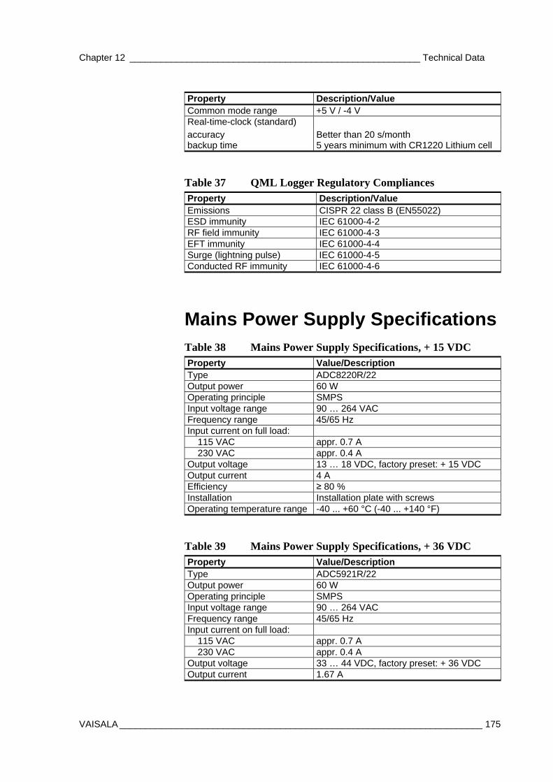
Chapter 12 ________________________________________________________ Technical Data
VAISALA ______________________________________________________________________ 175
Property Description/Value Common mode range +5 V / -4 V Real-time-clock (standard) accuracy Better than 20 s/month backup time 5 years minimum with CR1220 Lithium cell
Table 37 QML Logger Regulatory Compliances Property Description/Value Emissions CISPR 22 class B (EN55022) ESD immunity IEC 61000-4-2 RF field immunity IEC 61000-4-3 EFT immunity IEC 61000-4-4 Surge (lightning pulse) IEC 61000-4-5 Conducted RF immunity IEC 61000-4-6
Mains Power Supply Specifications Table 38 Mains Power Supply Specifications, + 15 VDC Property Value/Description Type ADC8220R/22 Output power 60 W Operating principle SMPS Input voltage range 90 … 264 VAC Frequency range 45/65 Hz Input current on full load: 115 VAC appr. 0.7 A 230 VAC appr. 0.4 A Output voltage 13 … 18 VDC, factory preset: + 15 VDC Output current 4 A Efficiency ≥ 80 % Installation Installation plate with screws Operating temperature range -40 ... +60 °C (-40 ... +140 °F)
Table 39 Mains Power Supply Specifications, + 36 VDC Property Value/Description Type ADC5921R/22 Output power 60 W Operating principle SMPS Input voltage range 90 … 264 VAC Frequency range 45/65 Hz Input current on full load: 115 VAC appr. 0.7 A 230 VAC appr. 0.4 A Output voltage 33 … 44 VDC, factory preset: + 36 VDC Output current 1.67 A
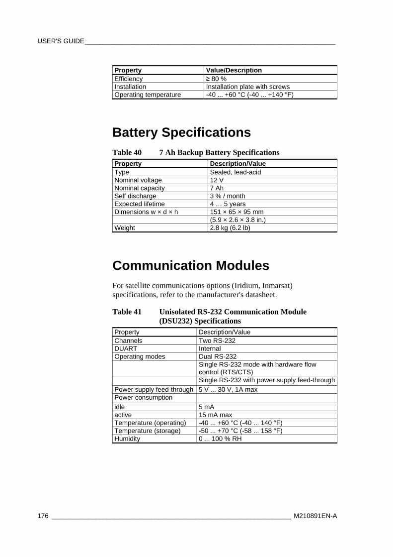
USER'S GUIDE____________________________________________________________________
176 _________________________________________________________________ M210891EN-A
Property Value/Description Efficiency ≥ 80 % Installation Installation plate with screws Operating temperature -40 ... +60 °C (-40 ... +140 °F)
Battery Specifications Table 40 7 Ah Backup Battery Specifications Property Description/Value Type Sealed, lead-acid Nominal voltage 12 V Nominal capacity 7 Ah Self discharge 3 % / month Expected lifetime 4 … 5 years Dimensions w × d × h 151 × 65 × 95 mm (5.9 × 2.6 × 3.8 in.) Weight 2.8 kg (6.2 lb)
Communication Modules For satellite communications options (Iridium, Inmarsat) specifications, refer to the manufacturer's datasheet.
Table 41 Unisolated RS-232 Communication Module (DSU232) Specifications
Property Description/Value Channels Two RS-232 DUART Internal Operating modes Dual RS-232 Single RS-232 mode with hardware flow
control (RTS/CTS) Single RS-232 with power supply feed-throughPower supply feed-through 5 V ... 30 V, 1A max Power consumption idle 5 mA active 15 mA max Temperature (operating) -40 ... +60 °C (-40 ... 140 °F) Temperature (storage) -50 ... +70 °C (-58 ... 158 °F) Humidity 0 ... 100 % RH
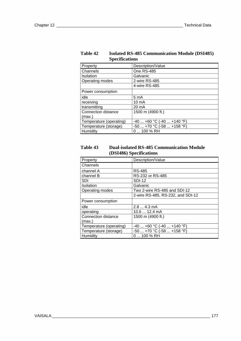
Chapter 12 ________________________________________________________ Technical Data
VAISALA ______________________________________________________________________ 177
Table 42 Isolated RS-485 Communication Module (DSI485) Specifications
Property Description/Value Channels One RS-485 Isolation Galvanic Operating modes 2-wire RS-485 4-wire RS-485 Power consumption idle 5 mA receiving 10 mA transmitting 20 mA Connection distance (max.)
1500 m (4900 ft.)
Temperature (operating) -40 ... +60 °C (-40 ... +140 °F) Temperature (storage) -50 ... +70 °C (-58 ... +158 °F) Humidity 0 ... 100 % RH
Table 43 Dual-isolated RS-485 Communication Module (DSI486) Specifications
Property Description/Value Channels channel A RS-485 channel B RS-232 or RS-485 SDI SDI-12 Isolation Galvanic Operating modes Two 2-wire RS-485 and SDI-12 2-wire RS-485, RS-232, and SDI-12 Power consumption idle 2.8 ... 4.3 mA operating 10.6 ... 12.4 mA Connection distance (max.)
1500 m (4900 ft.)
Temperature (operating) -40 ... +60 °C (-40 ... +140 °F) Temperature (storage) -50 ... +70 °C (-58 ... +158 °F) Humidity 0 ... 100 % RH
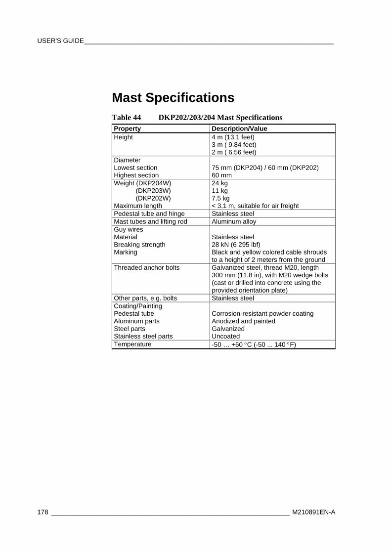
USER'S GUIDE____________________________________________________________________
178 _________________________________________________________________ M210891EN-A
Mast Specifications Table 44 DKP202/203/204 Mast Specifications Property Description/Value Height 4 m (13.1 feet)
3 m ( 9.84 feet) 2 m ( 6.56 feet)
Diameter Lowest section Highest section
75 mm (DKP204) / 60 mm (DKP202) 60 mm
Weight (DKP204W) (DKP203W) (DKP202W) Maximum length
24 kg 11 kg 7.5 kg < 3.1 m, suitable for air freight
Pedestal tube and hinge Stainless steel Mast tubes and lifting rod Aluminum alloy Guy wires Material Breaking strength Marking
Stainless steel 28 kN (6 295 lbf) Black and yellow colored cable shrouds to a height of 2 meters from the ground
Threaded anchor bolts Galvanized steel, thread M20, length 300 mm (11.8 in), with M20 wedge bolts (cast or drilled into concrete using the provided orientation plate)
Other parts, e.g. bolts Stainless steel Coating/Painting Pedestal tube Aluminum parts Steel parts Stainless steel parts
Corrosion-resistant powder coating Anodized and painted Galvanized Uncoated
Temperature -50 … +60 °C (-50 ... 140 °F)
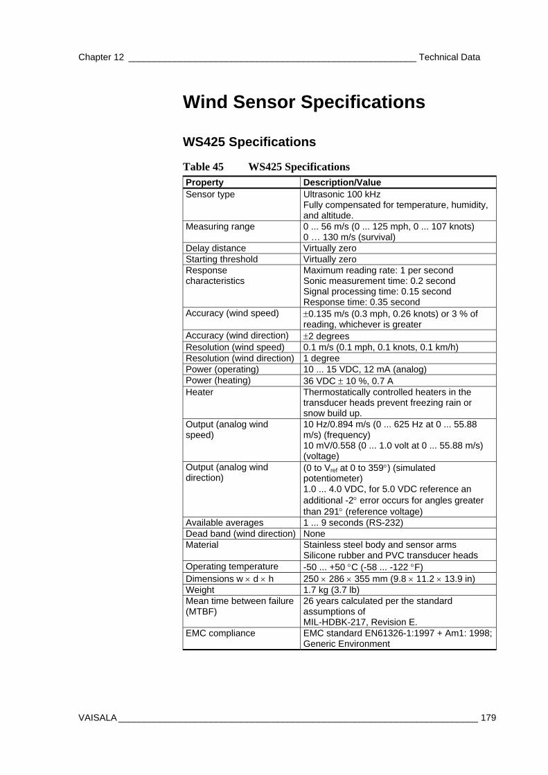
Chapter 12 ________________________________________________________ Technical Data
VAISALA ______________________________________________________________________ 179
Wind Sensor Specifications
WS425 Specifications
Table 45 WS425 Specifications Property Description/Value Sensor type Ultrasonic 100 kHz
Fully compensated for temperature, humidity, and altitude.
Measuring range 0 ... 56 m/s (0 ... 125 mph, 0 ... 107 knots) 0 … 130 m/s (survival)
Delay distance Virtually zero Starting threshold Virtually zero Response characteristics
Maximum reading rate: 1 per second Sonic measurement time: 0.2 second Signal processing time: 0.15 second Response time: 0.35 second
Accuracy (wind speed) ±0.135 m/s (0.3 mph, 0.26 knots) or 3 % of reading, whichever is greater
Accuracy (wind direction) ±2 degrees Resolution (wind speed) 0.1 m/s (0.1 mph, 0.1 knots, 0.1 km/h) Resolution (wind direction) 1 degree Power (operating) 10 ... 15 VDC, 12 mA (analog) Power (heating) 36 VDC ± 10 %, 0.7 A Heater Thermostatically controlled heaters in the
transducer heads prevent freezing rain or snow build up.
Output (analog wind speed)
10 Hz/0.894 m/s (0 ... 625 Hz at 0 ... 55.88 m/s) (frequency) 10 mV/0.558 (0 ... 1.0 volt at 0 ... 55.88 m/s) (voltage)
Output (analog wind direction)
(0 to Vref at 0 to 359°) (simulated potentiometer) 1.0 ... 4.0 VDC, for 5.0 VDC reference an additional -2° error occurs for angles greater than 291° (reference voltage)
Available averages 1 ... 9 seconds (RS-232) Dead band (wind direction) None Material Stainless steel body and sensor arms
Silicone rubber and PVC transducer heads Operating temperature -50 ... +50 °C (-58 ... -122 °F) Dimensions w × d × h 250 × 286 × 355 mm (9.8 × 11.2 × 13.9 in) Weight 1.7 kg (3.7 lb) Mean time between failure (MTBF)
26 years calculated per the standard assumptions of MIL-HDBK-217, Revision E.
EMC compliance EMC standard EN61326-1:1997 + Am1: 1998; Generic Environment
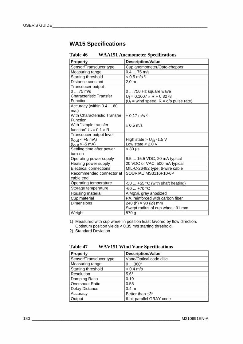
USER'S GUIDE____________________________________________________________________
180 _________________________________________________________________ M210891EN-A
WA15 Specifications
Table 46 WAA151 Anemometer Specifications Property Description/Value Sensor/Transducer type Cup anemometer/Opto-chopper Measuring range 0.4 ... 75 m/s Starting threshold < 0.5 m/s 1) Distance constant 2.0 m Transducer output 0 ... 75 m/s Characteristic Transfer Function
0 ... 750 Hz square wave Uf = 0.1007 × R + 0.3278 (Uf = wind speed; R = o/p pulse rate)
Accuracy (within 0.4 ... 60 m/s) With Characteristic Transfer Function With "simple transfer function" Uf = 0.1 × R
± 0.17 m/s 2)
± 0.5 m/s
Transducer output level (Iout < +5 mA) (Iout > -5 mA)
High state > Uin -1.5 V Low state < 2.0 V
Settling time after power turn-on
< 30 µs
Operating power supply 9.5 ... 15.5 VDC, 20 mA typical Heating power supply 20 VDC or VAC, 500 mA typical Electrical connections MIL-C-26482 type; 6-wire cable Recommended connector at cable end
SOURIAU MS3116F10-6P
Operating temperature -50 ... +55 °C (with shaft heating) Storage temperature -60 ... +70 °C Housing material AlMgSi, gray anodized Cup material PA, reinforced with carbon fiber Dimensions 240 (h) × 90 (Ø) mm
Swept radius of cup wheel: 91 mm Weight 570 g
1) Measured with cup wheel in position least favored by flow direction.
Optimum position yields < 0.35 m/s starting threshold. 2) Standard Deviation
Table 47 WAV151 Wind Vane Specifications Property Description/Value Sensor/Transducer type Vane/Optical code disc Measuring range 0 ... 360° Starting threshold < 0.4 m/s Resolution 5.6° Damping Ratio 0.19 Overshoot Ratio 0.55 Delay Distance 0.4 m Accuracy Better than ±3° Output 6-bit parallel GRAY code
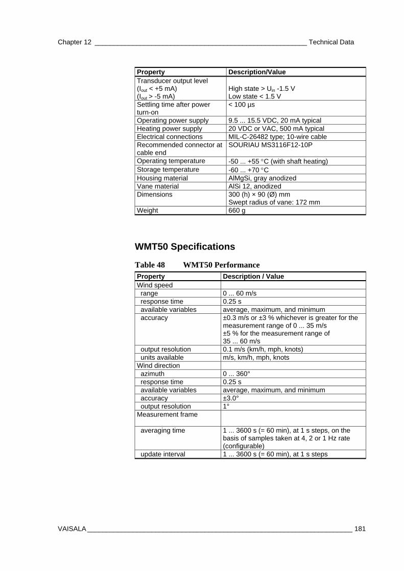
Chapter 12 ________________________________________________________ Technical Data
VAISALA ______________________________________________________________________ 181
Property Description/Value Transducer output level (Iout < +5 mA) (Iout > -5 mA)
High state > Uin -1.5 V Low state < 1.5 V
Settling time after power turn-on
< 100 µs
Operating power supply 9.5 ... 15.5 VDC, 20 mA typical Heating power supply 20 VDC or VAC, 500 mA typical Electrical connections MIL-C-26482 type; 10-wire cable Recommended connector at cable end
SOURIAU MS3116F12-10P
Operating temperature -50 ... +55 °C (with shaft heating) Storage temperature -60 ... +70 °C Housing material AlMgSi, gray anodized Vane material AlSi 12, anodized Dimensions 300 (h) × 90 (Ø) mm
Swept radius of vane: 172 mm Weight 660 g
WMT50 Specifications
Table 48 WMT50 Performance Property Description / Value Wind speed range 0 ... 60 m/s response time 0.25 s available variables average, maximum, and minimum accuracy ±0.3 m/s or ±3 % whichever is greater for the
measurement range of 0 ... 35 m/s ±5 % for the measurement range of 35 ... 60 m/s
output resolution 0.1 m/s (km/h, mph, knots) units available m/s, km/h, mph, knots Wind direction azimuth 0 ... 360° response time 0.25 s available variables average, maximum, and minimum accuracy ±3.0° output resolution 1° Measurement frame
averaging time
1 ... 3600 s (= 60 min), at 1 s steps, on the basis of samples taken at 4, 2 or 1 Hz rate (configurable)
update interval 1 ... 3600 s (= 60 min), at 1 s steps
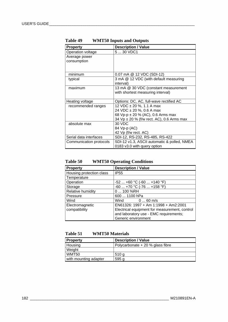
USER'S GUIDE____________________________________________________________________
182 _________________________________________________________________ M210891EN-A
Table 49 WMT50 Inputs and Outputs Property Description / Value Operation voltage 5 ... 30 VDC1 Average power consumption
minimum 0.07 mA @ 12 VDC (SDI-12) typical 3 mA @ 12 VDC (with default measuring
interval) maximum 13 mA @ 30 VDC (constant measurement
with shortest measuring interval)
Heating voltage Options: DC, AC, full-wave rectified AC recommended ranges 12 VDC ± 20 %, 1.1 A max
24 VDC ± 20 %, 0.6 A max 68 Vp-p ± 20 % (AC), 0.6 Arms max 34 Vp ± 20 % (f/w rect. AC), 0.6 Arms max
absolute max 30 VDC 84 Vp-p (AC) 42 Vp (f/w rect. AC)
Serial data interfaces SDI-12, RS-232, RS-485, RS-422 Communication protocols SDI-12 v1.3, ASCII automatic & polled, NMEA
0183 v3.0 with query option
Table 50 WMT50 Operating Conditions Property Description / Value Housing protection class IP55 Temperature Operation -52 ... +60 °C (-60 ... +140 °F) Storage -60 ... +70 °C (-76 ... +158 °F) Relative humidity 0 ... 100 %RH Pressure 600 ... 1100 hPa Wind Wind 0 ... 60 m/s Electromagnetic compatibility
EN61326: 1997 + Am 1:1998 + Am2:2001 Electrical equipment for measurement, control and laboratory use - EMC requirements; Generic environment
Table 51 WMT50 Materials Property Description / Value Housing Polycarbonate + 20 % glass fibre Weight WMT50 510 g with mounting adapter 595 g
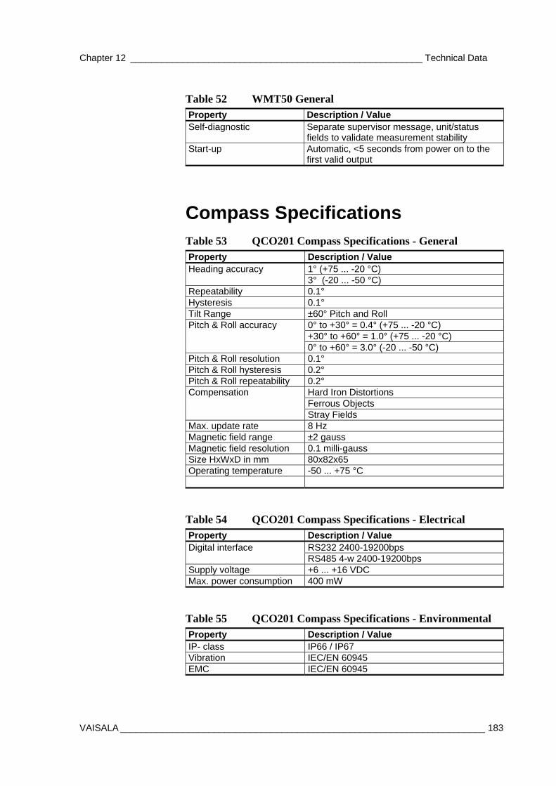
Chapter 12 ________________________________________________________ Technical Data
VAISALA ______________________________________________________________________ 183
Table 52 WMT50 General Property Description / Value Self-diagnostic Separate supervisor message, unit/status
fields to validate measurement stability Start-up Automatic, <5 seconds from power on to the
first valid output
Compass Specifications Table 53 QCO201 Compass Specifications - General Property Description / Value Heading accuracy 1° (+75 ... -20 °C) 3° (-20 ... -50 °C) Repeatability 0.1° Hysteresis 0.1° Tilt Range ±60° Pitch and Roll Pitch & Roll accuracy 0° to +30° = 0.4° (+75 ... -20 °C) +30° to +60° = 1.0° (+75 ... -20 °C) 0° to +60° = 3.0° (-20 ... -50 °C) Pitch & Roll resolution 0.1° Pitch & Roll hysteresis 0.2° Pitch & Roll repeatability 0.2° Compensation Hard Iron Distortions Ferrous Objects Stray Fields Max. update rate 8 Hz Magnetic field range ±2 gauss Magnetic field resolution 0.1 milli-gauss Size HxWxD in mm 80x82x65 Operating temperature -50 ... +75 °C
Table 54 QCO201 Compass Specifications - Electrical Property Description / Value Digital interface RS232 2400-19200bps RS485 4-w 2400-19200bps Supply voltage +6 ... +16 VDC Max. power consumption 400 mW
Table 55 QCO201 Compass Specifications - Environmental Property Description / Value IP- class IP66 / IP67 Vibration IEC/EN 60945 EMC IEC/EN 60945
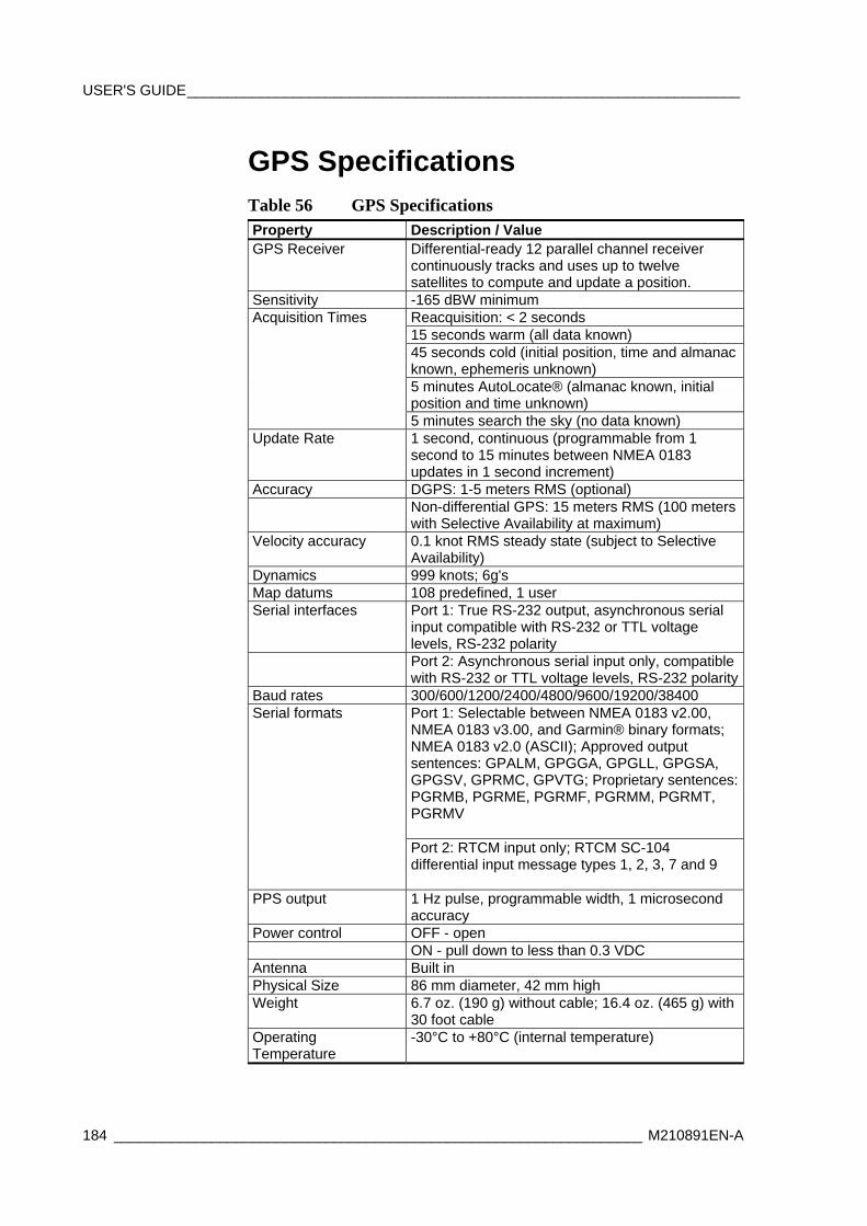
USER'S GUIDE____________________________________________________________________
184 _________________________________________________________________ M210891EN-A
GPS Specifications Table 56 GPS Specifications Property Description / Value GPS Receiver Differential-ready 12 parallel channel receiver
continuously tracks and uses up to twelve satellites to compute and update a position.
Sensitivity -165 dBW minimum Acquisition Times Reacquisition: < 2 seconds 15 seconds warm (all data known) 45 seconds cold (initial position, time and almanac
known, ephemeris unknown) 5 minutes AutoLocate® (almanac known, initial
position and time unknown) 5 minutes search the sky (no data known) Update Rate 1 second, continuous (programmable from 1
second to 15 minutes between NMEA 0183 updates in 1 second increment)
Accuracy DGPS: 1-5 meters RMS (optional) Non-differential GPS: 15 meters RMS (100 meters
with Selective Availability at maximum) Velocity accuracy 0.1 knot RMS steady state (subject to Selective
Availability) Dynamics 999 knots; 6g's Map datums 108 predefined, 1 user Serial interfaces Port 1: True RS-232 output, asynchronous serial
input compatible with RS-232 or TTL voltage levels, RS-232 polarity
Port 2: Asynchronous serial input only, compatible with RS-232 or TTL voltage levels, RS-232 polarity
Baud rates 300/600/1200/2400/4800/9600/19200/38400 Serial formats Port 1: Selectable between NMEA 0183 v2.00,
NMEA 0183 v3.00, and Garmin® binary formats; NMEA 0183 v2.0 (ASCII); Approved output sentences: GPALM, GPGGA, GPGLL, GPGSA, GPGSV, GPRMC, GPVTG; Proprietary sentences: PGRMB, PGRME, PGRMF, PGRMM, PGRMT, PGRMV
Port 2: RTCM input only; RTCM SC-104 differential input message types 1, 2, 3, 7 and 9
PPS output 1 Hz pulse, programmable width, 1 microsecond accuracy
Power control OFF - open ON - pull down to less than 0.3 VDC Antenna Built in Physical Size 86 mm diameter, 42 mm high Weight 6.7 oz. (190 g) without cable; 16.4 oz. (465 g) with
30 foot cable Operating Temperature
-30°C to +80°C (internal temperature)
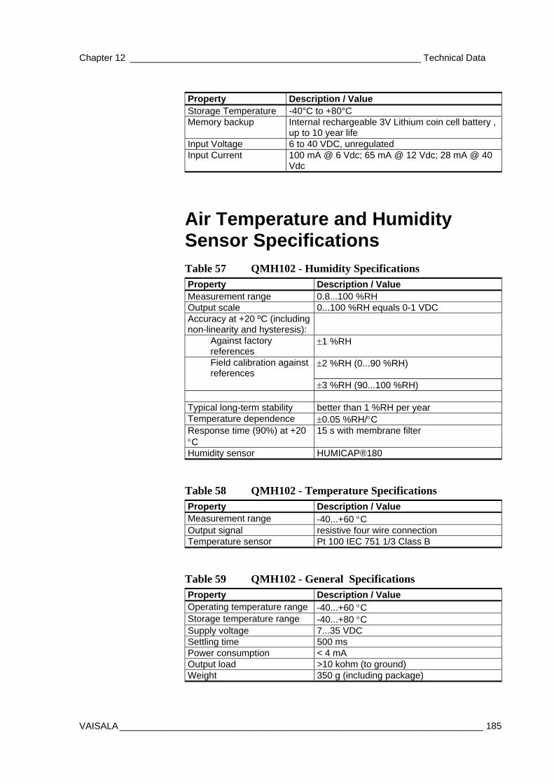
Chapter 12 ________________________________________________________ Technical Data
VAISALA ______________________________________________________________________ 185
Property Description / Value Storage Temperature -40°C to +80°C Memory backup Internal rechargeable 3V Lithium coin cell battery ,
up to 10 year life Input Voltage 6 to 40 VDC, unregulated Input Current 100 mA @ 6 Vdc; 65 mA @ 12 Vdc; 28 mA @ 40
Vdc
Air Temperature and Humidity Sensor Specifications Table 57 QMH102 - Humidity Specifications Property Description / Value Measurement range 0.8...100 %RH Output scale 0...100 %RH equals 0-1 VDC Accuracy at +20 ºC (including non-linearity and hysteresis):
Against factory references
±1 %RH
Field calibration against references
±2 %RH (0...90 %RH)
±3 %RH (90...100 %RH) Typical long-term stability better than 1 %RH per year Temperature dependence ±0.05 %RH/°C Response time (90%) at +20 °C
15 s with membrane filter
Humidity sensor HUMICAP®180
Table 58 QMH102 - Temperature Specifications Property Description / Value Measurement range -40...+60 °C Output signal resistive four wire connection Temperature sensor Pt 100 IEC 751 1/3 Class B
Table 59 QMH102 - General Specifications Property Description / Value Operating temperature range -40...+60 °C Storage temperature range -40...+80 °C Supply voltage 7...35 VDC Settling time 500 ms Power consumption < 4 mA Output load >10 kohm (to ground) Weight 350 g (including package)
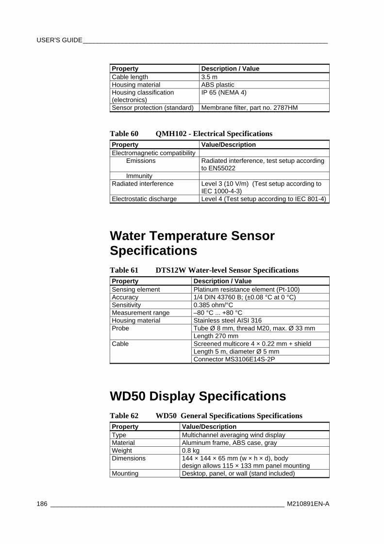
USER'S GUIDE____________________________________________________________________
186 _________________________________________________________________ M210891EN-A
Property Description / Value Cable length 3.5 m Housing material ABS plastic Housing classification (electronics)
IP 65 (NEMA 4)
Sensor protection (standard) Membrane filter, part no. 2787HM
Table 60 QMH102 - Electrical Specifications Property Value/Description Electromagnetic compatibility Emissions Radiated interference, test setup according
to EN55022 Immunity Radiated interference Level 3 (10 V/m) (Test setup according to
IEC 1000-4-3) Electrostatic discharge Level 4 (Test setup according to IEC 801-4)
Water Temperature Sensor Specifications Table 61 DTS12W Water-level Sensor Specifications Property Description / Value Sensing element Platinum resistance element (Pt-100) Accuracy 1/4 DIN 43760 B; (±0.08 °C at 0 °C) Sensitivity 0.385 ohm/°C Measurement range –80 °C ... +80 °C Housing material Stainless steel AISI 316 Probe Tube Ø 8 mm, thread M20, max. Ø 33 mm Length 270 mm Cable Screened multicore 4 × 0.22 mm + shield Length 5 m, diameter Ø 5 mm Connector MS3106E14S-2P
WD50 Display Specifications Table 62 WD50 General Specifications Specifications Property Value/Description Type Multichannel averaging wind display Material Aluminum frame, ABS case, gray Weight 0.8 kg Dimensions 144 × 144 × 65 mm (w × h × d), body
design allows 115 × 133 mm panel mounting Mounting Desktop, panel, or wall (stand included)

Chapter 12 _______________________________________________________Technical Data
VAISALA ______________________________________________________________________ 189
Property Value/Description heading text and alarm reason expression.
Operation Rotary switch 1 pc. Double action push button 1 pc. Display parameters configurable with a PC terminal program via a serial line.
Table 70 DD50 Input/Output Specifications Property Value/Description Serial I/O -opto-isolated RS-485 input.
Applicable to RS-232 or current loop. -2-wire RS-485 transceiver.
Optional I/O Communication module interface for isolated RS-485, modem, etc.
Analog inputs 4 Channels: Voltage 0 ... 2.5 V or Current 0 ... 20 mA for analog sensors/transmitters.
Parallel printer connection for dot matrix printer Relay coil drive 120 mA max. sink. Electrical connections
20 screw terminals 1.5 mm2 max. wire dimensions.Printer female DB-25 connector.
Table 71 DD50 Environmental Specifications Property Value/Description Storage temperature - 40 ... + 60 °C Operating temperature
+ 5 ... + 55 °C
Humidity Non-condensing EMC CE-compliant Vibration test According to IEC 68-2-64,
MIL-STD-167-1
The Digital display DD50 is designed to comply with the CE norms for electromagnetic compatibility. The DD50 has successfully passed the following emissions and immunity tests.
NOTE Tests have been done without grounding the cable shields to the display, which would further improve the situation, if needed.
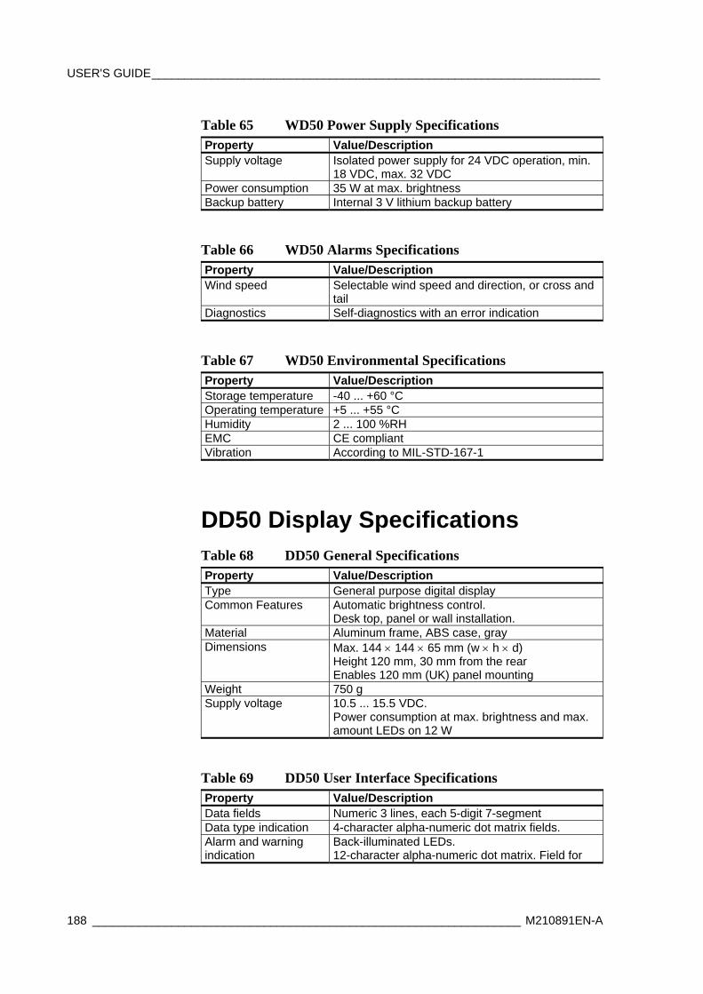
USER'S GUIDE____________________________________________________________________
188 _________________________________________________________________ M210891EN-A
Table 65 WD50 Power Supply Specifications Property Value/Description Supply voltage Isolated power supply for 24 VDC operation, min.
18 VDC, max. 32 VDC Power consumption 35 W at max. brightness Backup battery Internal 3 V lithium backup battery
Table 66 WD50 Alarms Specifications Property Value/Description Wind speed Selectable wind speed and direction, or cross and
tail Diagnostics Self-diagnostics with an error indication
Table 67 WD50 Environmental Specifications Property Value/Description Storage temperature -40 ... +60 °C Operating temperature +5 ... +55 °C Humidity 2 ... 100 %RH EMC CE compliant Vibration According to MIL-STD-167-1
DD50 Display Specifications Table 68 DD50 General Specifications Property Value/Description Type General purpose digital display Common Features Automatic brightness control.
Desk top, panel or wall installation. Material Aluminum frame, ABS case, gray Dimensions Max. 144 × 144 × 65 mm (w × h × d)
Height 120 mm, 30 mm from the rear Enables 120 mm (UK) panel mounting
Weight 750 g Supply voltage 10.5 ... 15.5 VDC.
Power consumption at max. brightness and max. amount LEDs on 12 W
Table 69 DD50 User Interface Specifications Property Value/Description Data fields Numeric 3 lines, each 5-digit 7-segment Data type indication 4-character alpha-numeric dot matrix fields. Alarm and warning indication
Back-illuminated LEDs. 12-character alpha-numeric dot matrix. Field for
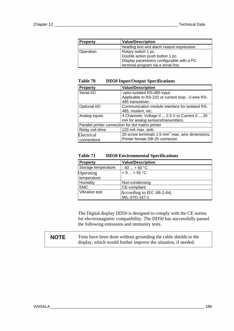
Chapter 12 ________________________________________________________ Technical Data
VAISALA ______________________________________________________________________ 189
Property Value/Description heading text and alarm reason expression.
Operation Rotary switch 1 pc. Double action push button 1 pc. Display parameters configurable with a PC terminal program via a serial line.
Table 70 DD50 Input/Output Specifications Property Value/Description Serial I/O -opto-isolated RS-485 input.
Applicable to RS-232 or current loop. -2-wire RS-485 transceiver.
Optional I/O Communication module interface for isolated RS-485, modem, etc.
Analog inputs 4 Channels: Voltage 0 ... 2.5 V or Current 0 ... 20 mA for analog sensors/transmitters.
Parallel printer connection for dot matrix printer Relay coil drive 120 mA max. sink. Electrical connections
20 screw terminals 1.5 mm2 max. wire dimensions.Printer female DB-25 connector.
Table 71 DD50 Environmental Specifications Property Value/Description Storage temperature - 40 ... + 60 °C Operating temperature
+ 5 ... + 55 °C
Humidity Non-condensing EMC CE-compliant Vibration test According to IEC 68-2-64,
MIL-STD-167-1
The Digital display DD50 is designed to comply with the CE norms for electromagnetic compatibility. The DD50 has successfully passed the following emissions and immunity tests.
NOTE Tests have been done without grounding the cable shields to the display, which would further improve the situation, if needed.
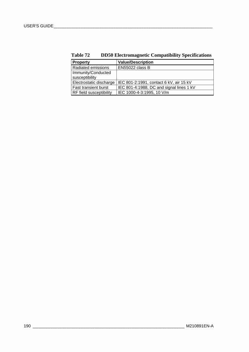
USER'S GUIDE____________________________________________________________________
190 _________________________________________________________________ M210891EN-A
Table 72 DD50 Electromagnetic Compatibility Specifications Property Value/Description Radiated emissions EN55022 class B Immunity/Conducted susceptibility
Electrostatic discharge IEC 801-2:1991, contact 6 kV, air 15 kV Fast transient burst IEC 801-4:1988, DC and signal lines 1 kV RF field susceptibility IEC 1000-4-3:1995, 10 V/m
Appendix A _________________________________________ FM-XII 13 SHIP Message Groups
VAISALA ______________________________________________________________________ 191
APPENDIX A
FM-XII 13 SHIP MESSAGE GROUPS
This appendix describes the FM-XII 13 Ship Message Groups.
General
Each group is described as follows:
Group: WMO / IMMT-3 standard identification of group Description: Data fields within group. If group contains several
variables, all of them are described. Optionality: Mandatory group is included in every message.
Optional group is only included if user enters data. Type: Automatic group is provided by data logger and PC.
Data of manual group is only included if user enters the data. If group is marked automatic/editable, it will be included automatically but observer may edit the value.
Restrictions: Any limitations that are applied to the coded data value either by data logger and/or PC.
Comments: Additional comments on the group. Note that static parameters are often defined both in data logger and in PC.
USER'S GUIDE____________________________________________________________________
192 _________________________________________________________________ M210891EN-A
Section 0 Groups
Group: MiMiMjMj Description: Report identification Optionality: Mandatory Type: Automatic Restrictions: Constant value “BBXX”. Comments: This value cannot be changed by the user.
Group: DDDD Description: Ship call sign Optionality: Mandatory Type: Automatic Restrictions: Freely chosen parameter, with maximum length of 8 characters. Comments: Static parameter.
Group: YYGGiw Description: 1) Day of month (YY) 2) Observation hour UTC (GG) 3) Wind indicator (iW) (0...1: m/s, 3...4: knots) Optionality: Mandatory. Type: Automatic. Restrictions: 1) Day of month (YY) must be valid day of month (1 ... 31) 2) Observation hour UTC (GG) must be valid hour (00…23) 3) Wind indicator (iW) value must be within code table 1855. Comments: Day of month and observation hour are automatically set by data logger / PC
clock. Wind indicator is a static parameter.
Group: 99LaLaLa Description: 1) Group identifier (99). 2) Latitude (LaLaLa). Optionality: Mandatory. Type: Automatic / editable Restrictions: 1) Group identifier (99) cannot be edited. 2) Latitude must be within values 000 … 900. Comments: Latitude will be included automatically if weather station is equipped with
positioning devices.
Appendix A _________________________________________ FM-XII 13 SHIP Message Groups
VAISALA ______________________________________________________________________ 193
Group: QcLoLoLoLo Description: 1) Quadrant of the globe (Qc). 2) Longitude (LoLoLoLo). Optionality: Mandatory. Type: Automatic / editable Restrictions: 1) Quadrant of the globe (Qc) within code table 3333. 2) Longitude must be within values 0000 ... 1800. Comments: Longitude will be included automatically if weather station is equipped with
positioning devices.
Section 1 Groups
Group: iRiXhVV Description: 1) Precipitation information indicator (iR). 2) Working methods of station (iX). 3) Altitude of the lowest cloud base station (h). 4) Horizontal visibility (VV). Optionality: Mandatory. Type: Automatic / editable (iR , iX ). Manual (h, VV). Restrictions: 1) Precipitation information indicator (iR) must be in code table 1819. 2) Working methods of station (iX) must be in code table 1860. 3) Altitude of the lowest cloud base station (h) must be in code table 1600. 4) Horizontal visibility (VV) must be in code table 4377. Comments: Cloud and visibility data will be included automatically if weather station is
equipped with ceilometers and present weather sensors.
Group: Nddff Description: 1) Total cloud coverage (N).
2) Wind direction, 10 min. average (dd). 3) Wind speed, 10 min. average (ff). Optionality: Mandatory. Type: Automatic / editable (dd, ff). Manual (N). Restrictions: 1) Total cloud coverage (N) must be in code table 2700. 2) Wind direction, 10 min. average (dd) must be within 00 ... 36. 3) Wind speed, 10 min. average (ff) must be within 00 … 99.
USER'S GUIDE____________________________________________________________________
194 _________________________________________________________________ M210891EN-A
Calm is indicated by dd = 00, ff =00. North wind is indicated by dd = 36. Comments: -
Group: 1SnTTT Description: 1) Group identifier (1).
2) Air temperature indicator (Sn). 3) Air temperature (TTT). Optionality: Mandatory. Type: Automatic / editable . Restrictions: 1) Group identifier (1) cannot be edited. 2) Air temperature indicator (Sn) must be in code table 3845. 3) Air temperature (TTT) must be within 000 … 999. Comments: -
Group: 2SnTdTdTd Description: 1) Group identifier (2).
2) Dew point temperature indicator (Sn). 3) Dew point temperature (TdTdTd). Optionality: Mandatory. Type: Automatic / editable. Restrictions: 1) Group identifier (2) cannot be edited. 2) Dew point temperature indicator (Sn) must be in code table 3845. 3) Dew point temperature (TdTdTd) must be within 000 … 999. Comments: Additional data validation constraints are included within the application.
Group: 4PPPP Description: 1) Group identifier (4).
2) Pressure reduced to mean sea level (PPPP). Optionality: Mandatory. Type: Automatic / editable. Restrictions: 1) Group identifier (4) cannot be edited. 2) Pressure reduced to mean sea level (PPPP) must be within 0000 … 0850 or
8700 … 9999. Comments: -
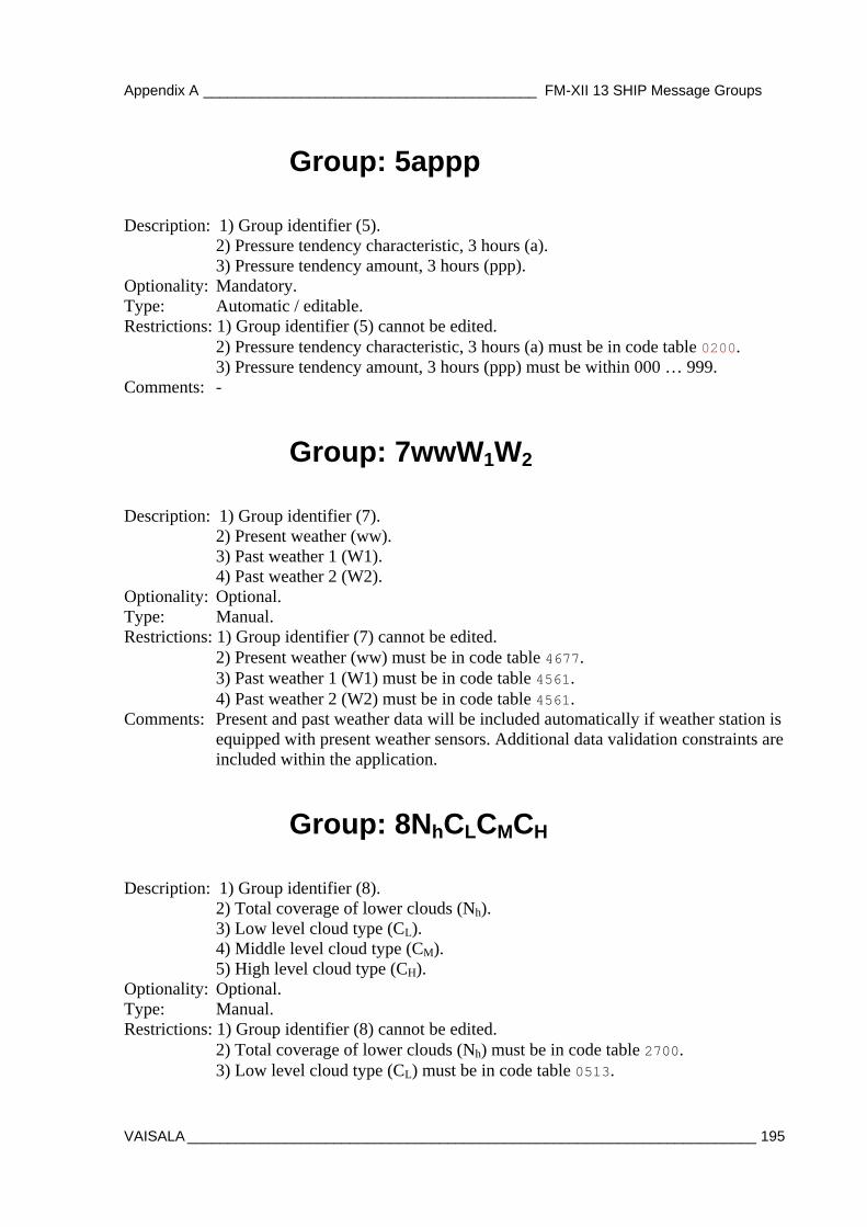
Appendix A _________________________________________ FM-XII 13 SHIP Message Groups
VAISALA ______________________________________________________________________ 195
Group: 5appp Description: 1) Group identifier (5).
2) Pressure tendency characteristic, 3 hours (a). 3) Pressure tendency amount, 3 hours (ppp).
Optionality: Mandatory. Type: Automatic / editable. Restrictions: 1) Group identifier (5) cannot be edited. 2) Pressure tendency characteristic, 3 hours (a) must be in code table 0200. 3) Pressure tendency amount, 3 hours (ppp) must be within 000 … 999. Comments: -
Group: 7wwW1W2 Description: 1) Group identifier (7).
2) Present weather (ww). 3) Past weather 1 (W1). 4) Past weather 2 (W2).
Optionality: Optional. Type: Manual. Restrictions: 1) Group identifier (7) cannot be edited. 2) Present weather (ww) must be in code table 4677. 3) Past weather 1 (W1) must be in code table 4561.
4) Past weather 2 (W2) must be in code table 4561. Comments: Present and past weather data will be included automatically if weather station is
equipped with present weather sensors. Additional data validation constraints are included within the application.
Group: 8NhCLCMCH Description: 1) Group identifier (8).
2) Total coverage of lower clouds (Nh). 3) Low level cloud type (CL). 4) Middle level cloud type (CM). 5) High level cloud type (CH).
Optionality: Optional. Type: Manual. Restrictions: 1) Group identifier (8) cannot be edited. 2) Total coverage of lower clouds (Nh) must be in code table 2700. 3) Low level cloud type (CL) must be in code table 0513.
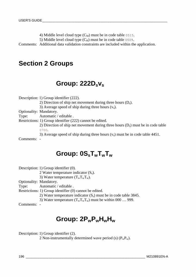
USER'S GUIDE____________________________________________________________________
196 _________________________________________________________________ M210891EN-A
4) Middle level cloud type (CM) must be in code table 0515. 5) Middle level cloud type (CH) must be in code table 0509.
Comments: Additional data validation constraints are included within the application.
Section 2 Groups
Group: 222Dsvs Description: 1) Group identifier (222).
2) Direction of ship net movement during three hours (Ds). 3) Average speed of ship during three hours (vs). Optionality: Mandatory. Type: Automatic / editable . Restrictions: 1) Group identifier (222) cannot be edited. 2) Direction of ship net movement during three hours (Ds) must be in code table
0700. 3) Average speed of ship during three hours (vs) must be in code table 4451. Comments: -
Group: 0SsTwTwTw Description: 1) Group identifier (0).
2 Water temperature indicator (Ss). 3) Water temperature (TwTwTw). Optionality: Mandatory. Type: Automatic / editable . Restrictions: 1) Group identifier (0) cannot be edited. 2) Water temperature indicator (Ss) must be in code table 3845. 3) Water temperature (TwTwTw) must be within 000 … 999. Comments: -
Group: 2PwPwHwHw Description: 1) Group identifier (2).
2 Non-instrumentally determined wave period (s) (PwPw).
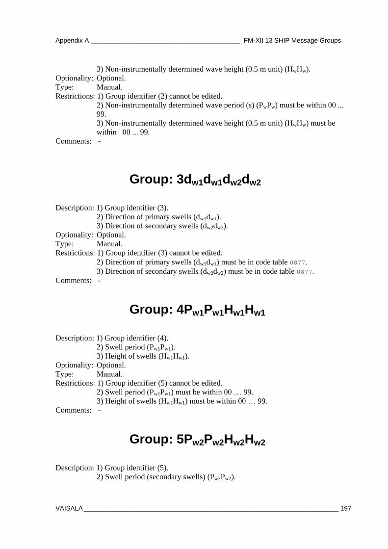
Appendix A _________________________________________ FM-XII 13 SHIP Message Groups
VAISALA ______________________________________________________________________ 197
3) Non-instrumentally determined wave height (0.5 m unit) (HwHw). Optionality: Optional. Type: Manual. Restrictions: 1) Group identifier (2) cannot be edited. 2) Non-instrumentally determined wave period (s) (PwPw) must be within 00 ...
99. 3) Non-instrumentally determined wave height (0.5 m unit) (HwHw) must be
within 00 ... 99. Comments: -
Group: 3dw1dw1dw2dw2 Description: 1) Group identifier (3).
2) Direction of primary swells (dw1dw1). 3) Direction of secondary swells (dw2dw2). Optionality: Optional. Type: Manual. Restrictions: 1) Group identifier (3) cannot be edited. 2) Direction of primary swells (dw1dw1) must be in code table 0877. 3) Direction of secondary swells (dw2dw2) must be in code table 0877. Comments: -
Group: 4Pw1Pw1Hw1Hw1 Description: 1) Group identifier (4).
2) Swell period (Pw1Pw1). 3) Height of swells (Hw1Hw1). Optionality: Optional. Type: Manual. Restrictions: 1) Group identifier (5) cannot be edited. 2) Swell period (Pw1Pw1) must be within 00 … 99. 3) Height of swells (Hw1Hw1) must be within 00 … 99. Comments: -
Group: 5Pw2Pw2Hw2Hw2 Description: 1) Group identifier (5).
2) Swell period (secondary swells) (Pw2Pw2).
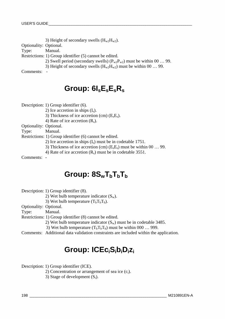
USER'S GUIDE____________________________________________________________________
198 _________________________________________________________________ M210891EN-A
3) Height of secondary swells (Hw2Hw2). Optionality: Optional. Type: Manual. Restrictions: 1) Group identifier (5) cannot be edited. 2) Swell period (secondary swells) (Pw2Pw2) must be within 00 … 99. 3) Height of secondary swells (Hw2Hw2) must be within 00 … 99. Comments: -
Group: 6IsEsEsRs Description: 1) Group identifier (6).
2) Ice accretion in ships (Is). 3) Thickness of ice accretion (cm) (EsEs).
4) Rate of ice accretion (Rs). Optionality: Optional. Type: Manual. Restrictions: 1) Group identifier (6) cannot be edited. 2) Ice accretion in ships (Is) must be in codetable 1751. 3) Thickness of ice accretion (cm) (EsEs) must be within 00 … 99.
4) Rate of ice accretion (Rs) must be in codetable 3551. Comments: -
Group: 8SwTbTbTb Description: 1) Group identifier (8).
2) Wet bulb temperature indicator (Sw). 3) Wet bulb temperature (TbTbTb). Optionality: Optional. Type: Manual. Restrictions: 1) Group identifier (8) cannot be edited. 2) Wet bulb temperature indicator (Sw) must be in codetable 3485. 3) Wet bulb temperature (TbTbTb) must be within 000 … 999. Comments: Additional data validation constraints are included within the application.
Group: ICEciSibiDizi Description: 1) Group identifier (ICE).
2) Concentration or arrangement of sea ice (ci). 3) Stage of development (Si).
Appendix A _________________________________________ FM-XII 13 SHIP Message Groups
VAISALA ______________________________________________________________________ 199
4) Ice of land origin (bi). 5) True bearing of principal ice edge (Di).
6) Present ice situation and trend over preceding three hours (zi). Optionality: Optional. Type: Manual. Restrictions: 1) Group identifier (ICE) cannot be edited.
2) Concentration or arrangement of sea ice (ci) must be in codetable 0639. 3) Stage of development (Si) must be in codetable 5239. 4) Ice of land origin (bi) must be in codetable 0439. 5) True bearing of principal ice edge (Di) must be in codetable 0739. 6) Present ice situation and trend over preceding three hours (zi) must be in
codetable 5239.

USER'S GUIDE____________________________________________________________________
200 _________________________________________________________________ M210891EN-A
This page intentionally left blank.

Appendix B ________________________________________________ IMMT-3 Message Groups
VAISALA ______________________________________________________________________ 201
APPENDIX B
IMMT-3 MESSAGE GROUPS
This chapter contains the description of the IMMT-3 Message groups.
See the following pages.

IOC-WMO/JCOMM-II/3s Appendix B – page 22
Annex 1 to Recommendation 9 (JCOMM-II)
AMENDMENTS TO THE MANUAL ON MARINE METEOROLOGICAL SERVICES AND
GUIDE TO MARINE METEOROLOGICAL SERVICES
LAYOUT FOR THE INTERNATIONAL MARITIME METEOROLOGICAL TAPE (IMMT)
[VERSION IMMT-3]
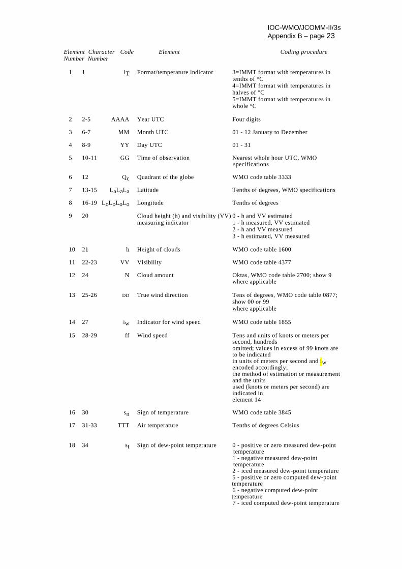
IOC-WMO/JCOMM-II/3s Appendix B – page 23
Element Character Code Element Coding procedure Number Number
1 1 iT Format/temperature indicator 3=IMMT format with temperatures in tenths of °C 4=IMMT format with temperatures in halves of °C 5=IMMT format with temperatures in whole °C 2 2-5 AAAA Year UTC Four digits 3 6-7 MM Month UTC 01 - 12 January to December 4 8-9 YY Day UTC 01 - 31 5 10-11 GG Time of observation Nearest whole hour UTC, WMO specifications 6 12 Qc Quadrant of the globe WMO code table 3333 7 13-15 LaLaLa Latitude Tenths of degrees, WMO specifications 8 16-19 LoLoLoLo Longitude Tenths of degrees 9 20 Cloud height (h) and visibility (VV) 0 - h and VV estimated measuring indicator 1 - h measured, VV estimated 2 - h and VV measured 3 - h estimated, VV measured 10 21 h Height of clouds WMO code table 1600 11 22-23 VV Visibility WMO code table 4377 12 24 N Cloud amount Oktas, WMO code table 2700; show 9 where applicable 13 25-26 DD True wind direction Tens of degrees, WMO code table 0877; show 00 or 99 where applicable 14 27 iw Indicator for wind speed WMO code table 1855 15 28-29 ff Wind speed Tens and units of knots or meters per second, hundreds omitted; values in excess of 99 knots are to be indicated in units of meters per second and iw encoded accordingly; the method of estimation or measurement and the units used (knots or meters per second) are indicated in element 14 16 30 sn Sign of temperature WMO code table 3845 17 31-33 TTT Air temperature Tenths of degrees Celsius
18 34 st Sign of dew-point temperature 0 - positive or zero measured dew-point temperature 1 - negative measured dew-point temperature 2 - iced measured dew-point temperature
5 - positive or zero computed dew-point temperature
6 - negative computed dew-point temperature 7 - iced computed dew-point temperature
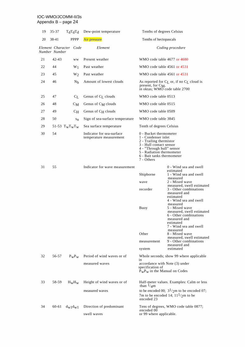
IOC-WMO/JCOMM-II/3s Appendix B – page 24
19 35-37 TdTdTd Dew-point temperature Tenths of degrees Celsius 20 38-41 PPPP Air pressure Tenths of hectopascals
Element Character Code Element Coding procedure Number Number
21 42-43 ww Present weather WMO code table 4677 or 4680 22 44 W1 Past weather WMO code table 4561 or 4531 23 45 W2 Past weather WMO code table 4561 or 4531 24 46 Nh Amount of lowest clouds As reported for CL or, if no CL cloud is present, for CM, in oktas; WMO code table 2700 25 47 CL Genus of CL clouds WMO code table 0513 26 48 CM Genus of CM clouds WMO code table 0515 27 49 CH Genus of CH clouds WMO code table 0509 28 50 sn Sign of sea-surface temperature WMO code table 3845 29 51-53 TwTwTw Sea surface temperature Tenth of degrees Celsius 30 54 Indicator for sea-surface 0 - Bucket thermometer temperature measurement 1 - Condenser inlet 2 - Trailing thermistor 3 - Hull contact sensor 4 - ”Through hull” sensor 5 - Radiation thermometer 6 - Bait tanks thermometer 7 - Others 31 55 Indicator for wave measurement 0 - Wind sea and swell estimated Shipborne 1 - Wind sea and swell measured wave 2 - Mixed wave measured, swell estimated recorder 3 - Other combinations measured and estimated 4 - Wind sea and swell measured Buoy 5 - Mixed wave measured, swell estimated 6 - Other combinations measured and estimated 7 - Wind sea and swell measured Other 8 - Mixed wave measured, swell estimated measurement 9 - Other combinations measured and system estimated 32 56-57 PwPw Period of wind waves or of Whole seconds; show 99 where applicable in measured waves accordance with Note (3) under specification of PwPw in the Manual on Codes 33 58-59 HwHw Height of wind waves or of Half-meter values. Examples: Calm or less than 1/4m
measured waves to be encoded 00; 31/2m to be encoded 07; 7m to be encoded 14; 111/2m to be encoded 23 34 60-61 dw1dw1 Direction of predominant Tens of degrees, WMO code table 0877; encoded 00 swell waves or 99 where applicable.
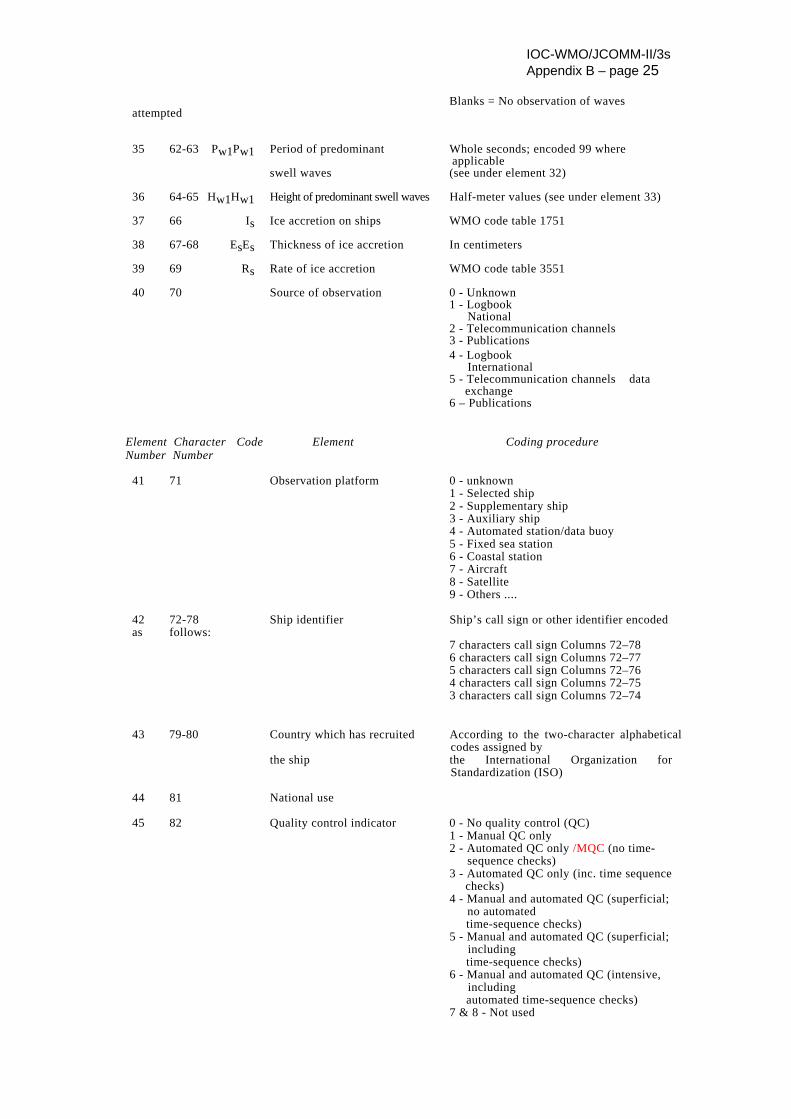
IOC-WMO/JCOMM-II/3s Appendix B – page 25
Blanks = No observation of waves attempted 35 62-63 Pw1Pw1 Period of predominant Whole seconds; encoded 99 where applicable swell waves (see under element 32) 36 64-65 Hw1Hw1 Height of predominant swell waves Half-meter values (see under element 33) 37 66 Is Ice accretion on ships WMO code table 1751 38 67-68 EsEs Thickness of ice accretion In centimeters 39 69 Rs Rate of ice accretion WMO code table 3551 40 70 Source of observation 0 - Unknown 1 - Logbook National 2 - Telecommunication channels 3 - Publications 4 - Logbook International 5 - Telecommunication channels data exchange 6 – Publications
Element Character Code Element Coding procedure Number Number
41 71 Observation platform 0 - unknown 1 - Selected ship 2 - Supplementary ship 3 - Auxiliary ship 4 - Automated station/data buoy 5 - Fixed sea station 6 - Coastal station 7 - Aircraft 8 - Satellite 9 - Others .... 42 72-78 Ship identifier Ship’s call sign or other identifier encoded as follows: 7 characters call sign Columns 72–78 6 characters call sign Columns 72–77 5 characters call sign Columns 72–76 4 characters call sign Columns 72–75 3 characters call sign Columns 72–74
43 79-80 Country which has recruited According to the two-character alphabetical codes assigned by
the ship the International Organization for Standardization (ISO)
44 81 National use 45 82 Quality control indicator 0 - No quality control (QC) 1 - Manual QC only 2 - Automated QC only /MQC (no time- sequence checks) 3 - Automated QC only (inc. time sequence checks) 4 - Manual and automated QC (superficial; no automated time-sequence checks) 5 - Manual and automated QC (superficial; including time-sequence checks) 6 - Manual and automated QC (intensive, including automated time-sequence checks) 7 & 8 - Not used
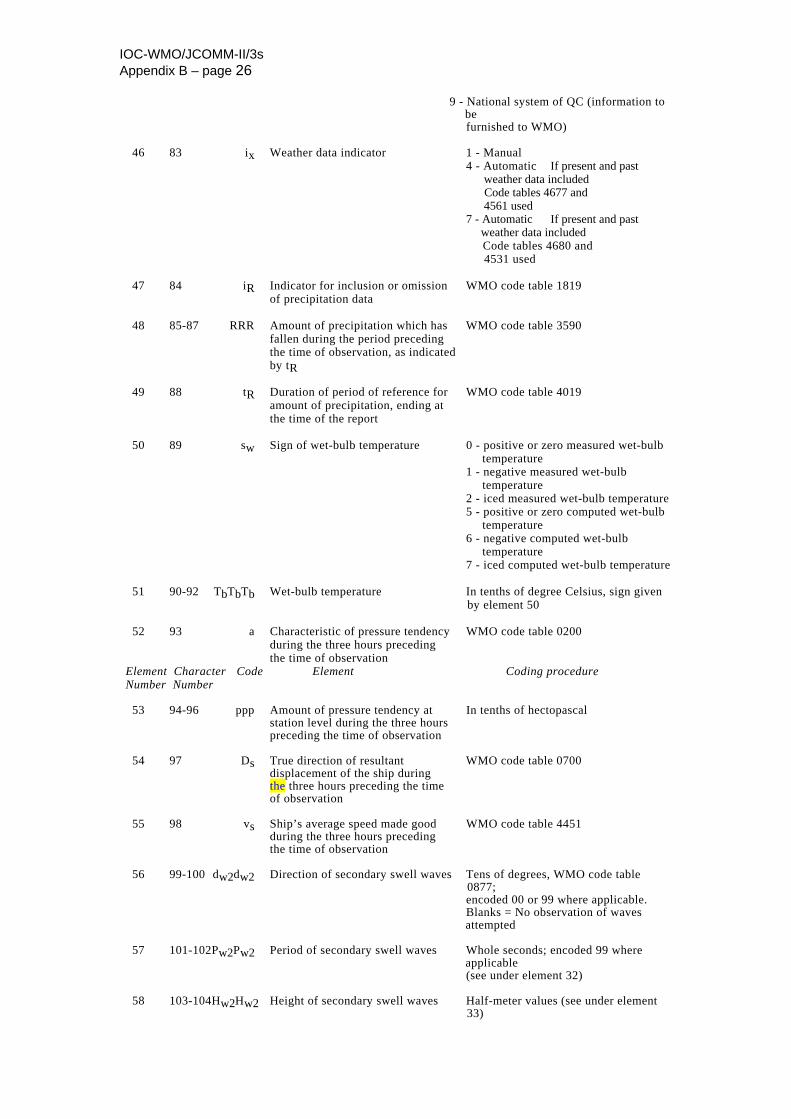
IOC-WMO/JCOMM-II/3s Appendix B – page 26
9 - National system of QC (information to be furnished to WMO) 46 83 ix Weather data indicator 1 - Manual 4 - Automatic If present and past weather data included Code tables 4677 and 4561 used 7 - Automatic If present and past weather data included Code tables 4680 and 4531 used 47 84 iR Indicator for inclusion or omission WMO code table 1819 of precipitation data 48 85-87 RRR Amount of precipitation which has WMO code table 3590 fallen during the period preceding the time of observation, as indicated by tR 49 88 tR Duration of period of reference for WMO code table 4019 amount of precipitation, ending at the time of the report 50 89 sw Sign of wet-bulb temperature 0 - positive or zero measured wet-bulb temperature 1 - negative measured wet-bulb temperature 2 - iced measured wet-bulb temperature 5 - positive or zero computed wet-bulb temperature 6 - negative computed wet-bulb temperature 7 - iced computed wet-bulb temperature 51 90-92 TbTbTb Wet-bulb temperature In tenths of degree Celsius, sign given by element 50 52 93 a Characteristic of pressure tendency WMO code table 0200 during the three hours preceding the time of observation
Element Character Code Element Coding procedure Number Number
53 94-96 ppp Amount of pressure tendency at In tenths of hectopascal station level during the three hours preceding the time of observation 54 97 Ds True direction of resultant WMO code table 0700 displacement of the ship during the three hours preceding the time
of observation 55 98 vs Ship’s average speed made good WMO code table 4451 during the three hours preceding the time of observation 56 99-100 dw2dw2 Direction of secondary swell waves Tens of degrees, WMO code table 0877; encoded 00 or 99 where applicable. Blanks = No observation of waves attempted 57 101-102Pw2Pw2 Period of secondary swell waves Whole seconds; encoded 99 where applicable (see under element 32) 58 103-104Hw2Hw2 Height of secondary swell waves Half-meter values (see under element 33)
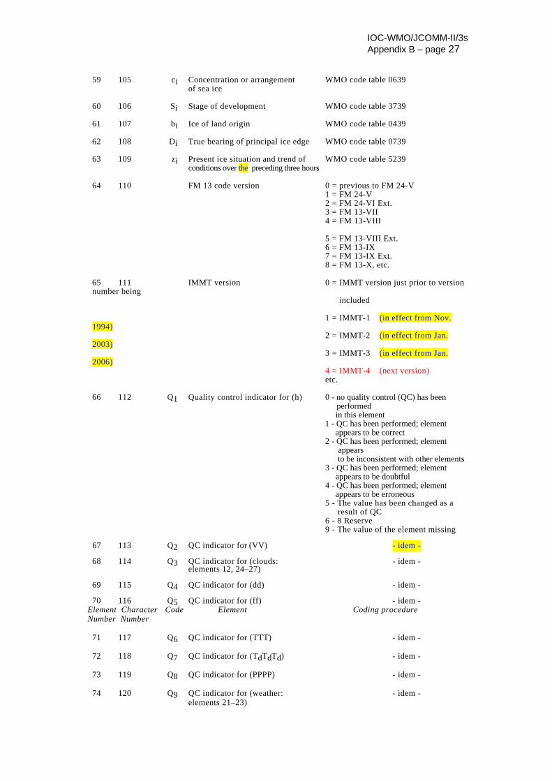
IOC-WMO/JCOMM-II/3s Appendix B – page 27
59 105 ci Concentration or arrangement WMO code table 0639 of sea ice 60 106 Si Stage of development WMO code table 3739 61 107 bi Ice of land origin WMO code table 0439 62 108 Di True bearing of principal ice edge WMO code table 0739 63 109 zi Present ice situation and trend of WMO code table 5239 conditions over the preceding three hours 64 110 FM 13 code version 0 = previous to FM 24-V 1 = FM 24-V 2 = FM 24-VI Ext. 3 = FM 13-VII 4 = FM 13-VIII 5 = FM 13-VIII Ext. 6 = FM 13-IX 7 = FM 13-IX Ext. 8 = FM 13-X, etc. 65 111 IMMT version 0 = IMMT version just prior to version number being included 1 = IMMT-1 (in effect from Nov. 1994) 2 = IMMT-2 (in effect from Jan. 2003) 3 = IMMT-3 (in effect from Jan. 2006) 4 = IMMT-4 (next version) etc. 66 112 Q1 Quality control indicator for (h) 0 - no quality control (QC) has been performed in this element 1 - QC has been performed; element appears to be correct 2 - QC has been performed; element appears to be inconsistent with other elements 3 - QC has been performed; element appears to be doubtful 4 - QC has been performed; element appears to be erroneous 5 - The value has been changed as a result of QC 6 - 8 Reserve 9 - The value of the element missing 67 113 Q2 QC indicator for (VV) - idem - 68 114 Q3 QC indicator for (clouds: - idem - elements 12, 24–27) 69 115 Q4 QC indicator for (dd) - idem - 70 116 Q5 QC indicator for (ff) - idem -
Element Character Code Element Coding procedure Number Number
71 117 Q6 QC indicator for (TTT) - idem - 72 118 Q7 QC indicator for (TdTdTd) - idem - 73 119 Q8 QC indicator for (PPPP) - idem - 74 120 Q9 QC indicator for (weather: - idem - elements 21–23)
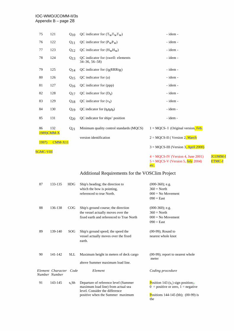
IOC-WMO/JCOMM-II/3s Appendix B – page 28
75 121 Q10 QC indicator for (TwTwTw) - idem - 76 122 Q11 QC indicator for (PwPw) - idem - 77 123 Q12 QC indicator for (HwHw) - idem - 78 124 Q13 QC indicator for (swell: elements - idem - 34–36, 56–58) 79 125 Q14 QC indicator for (iRRRRtR) - idem - 80 126 Q15 QC indicator for (a) - idem - 81 127 Q16 QC indicator for (ppp) - idem - 82 128 Q17 QC indicator for (Ds) - idem - 83 129 Q18 QC indicator for (vs) - idem -
84 130 Q19 QC indicator for (tbtbtb) - idem - 85 131 Q20 QC indicator for ships’ position - idem - 86 132 Q21 Minimum quality control standards (MQCS) 1 = MQCS- I (Original version, Feb. 1989)CMM-X version identification 2 = MQCS-II ( Version 2, March 1997) CMM-X11
3 = MQCS-III (Version 3, April 2000) SGMC-VIII 4 = MQCS-IV (Version 4, June 2001) JCOMM-I 5 = MQCS-V (Version 5, July 2004) ETMC-I etc.
Additional Requirements for the VOSClim Project 87 133-135 HDG Ship's heading; the direction to (000-360); e.g. which the bow is pointing, 360 = North referenced to true North. 000 = No Movement 090 = East 88 136-138 COG Ship's ground course; the direction (000-360); e.g. the vessel actually moves over the 360 = North fixed earth and referenced to True North 000 = No Movement 090 = East 89 139-140 SOG Ship's ground speed; the speed the (00-99); Round to vessel actually moves over the fixed nearest whole knot earth.
90 141-142 SLL Maximum height in meters of deck cargo (00-99); report to nearest whole meter above Summer maximum load line.
Element Character Code Element Coding procedure Number Number
91 143-145 sLhh Departure of reference level (Summer Position 143 (sL) sign position;, maximum load line) from actual sea 0 = positive or zero, 1 = negative level. Consider the difference positive when the Summer maximum Positions 144-145 (hh); (00-99) is the
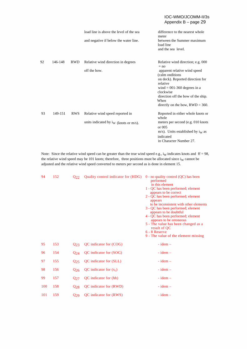
IOC-WMO/JCOMM-II/3s Appendix B – page 29
load line is above the level of the sea difference to the nearest whole
meter and negative if below the water line. between the Summer maximum
load line and the sea level.
92 146-148 RWD Relative wind direction in degrees Relative wind direction; e.g. 000 = no off the bow. apparent relative wind speed (calm onditions on deck). Reported direction for relative wind = 001-360 degrees in a clockwise
direction off the bow of the ship. When directly on the bow, RWD = 360.
93 149-151 RWS Relative wind speed reported in Reported in either whole knots or whole units indicated by iW (knots or m/s). meters per second (e.g. 010 knots or 005 m/s). Units established by iW as indicated in Character Number 27. Note: Since the relative wind speed can be greater than the true wind speed e.g., iW indicates knots and ff = 98, the relative wind speed may be 101 knots; therefore, three positions must be allocated since iW cannot be adjusted and the relative wind speed converted to meters per second as is done in element 15.
94 152 Q22 Quality control indicator for (HDG) 0 - no quality control (QC) has been performed in this element 1 - QC has been performed; element appears to be correct 2 - QC has been performed; element appears to be inconsistent with other elements 3 - QC has been performed; element appears to be doubtful 4 - QC has been performed; element appears to be erroneous 5 - The value has been changed as a result of QC 6 - 8 Reserve 9 - The value of the element missing 95 153 Q23 QC indicator for (COG) - idem –
96 154 Q24 QC indicator for (SOG) - idem –
97 155 Q25 QC indicator for (SLL) - idem –
98 156 Q26 QC indicator for (SL) - idem –
99 157 Q27 QC indicator for (hh) - idem –
100 158 Q28 QC indicator for (RWD) - idem –
101 159 Q29 QC indicator for (RWS) - idem -
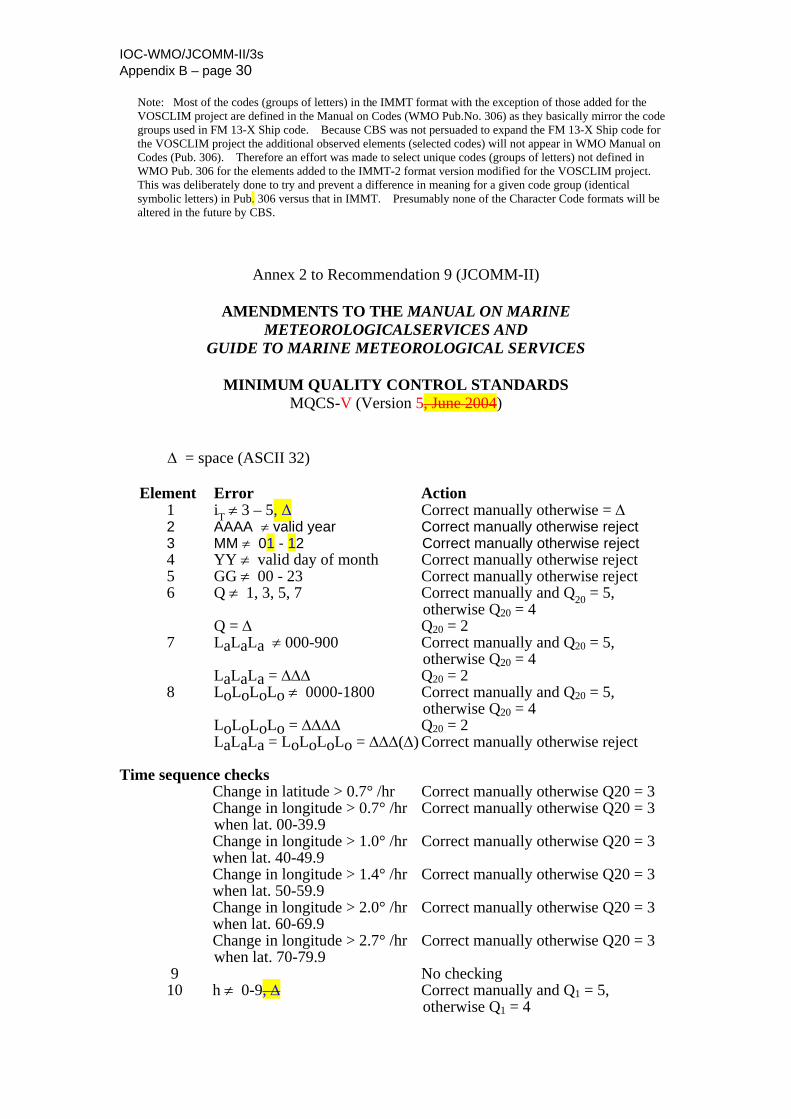
IOC-WMO/JCOMM-II/3s Appendix B – page 30
Note: Most of the codes (groups of letters) in the IMMT format with the exception of those added for the VOSCLIM project are defined in the Manual on Codes (WMO Pub.No. 306) as they basically mirror the code groups used in FM 13-X Ship code. Because CBS was not persuaded to expand the FM 13-X Ship code for the VOSCLIM project the additional observed elements (selected codes) will not appear in WMO Manual on Codes (Pub. 306). Therefore an effort was made to select unique codes (groups of letters) not defined in WMO Pub. 306 for the elements added to the IMMT-2 format version modified for the VOSCLIM project. This was deliberately done to try and prevent a difference in meaning for a given code group (identical symbolic letters) in Pub. 306 versus that in IMMT. Presumably none of the Character Code formats will be altered in the future by CBS.
Annex 2 to Recommendation 9 (JCOMM-II)
AMENDMENTS TO THE MANUAL ON MARINE METEOROLOGICALSERVICES AND
GUIDE TO MARINE METEOROLOGICAL SERVICES
MINIMUM QUALITY CONTROL STANDARDS MQCS-V (Version 5, June 2004)
Δ = space (ASCII 32) Element Error Action 1 i ≠ 3 – 5, Δ Correct manually otherwise = Δ T 2 AAAA ≠ valid year Correct manually otherwise reject 3 MM ≠ 01 - 12 Correct manually otherwise reject 4 YY ≠ valid day of month Correct manually otherwise reject 5 GG ≠ 00 - 23 Correct manually otherwise reject 6 Q ≠ 1, 3, 5, 7 Correct manually and Q20 = 5, otherwise Q20 = 4 Q = Δ Q20 = 2 7 LaLaLa ≠ 000-900 Correct manually and Q20 = 5, otherwise Q20 = 4 LaLaLa = ΔΔΔ Q20 = 2 8 LoLoLoLo ≠ 0000-1800 Correct manually and Q20 = 5, otherwise Q20 = 4 LoLoLoLo = ΔΔΔΔ Q20 = 2 LaLaLa = LoLoLoLo = ΔΔΔ(Δ) Correct manually otherwise reject Time sequence checks Change in latitude > 0.7° /hr Correct manually otherwise Q20 = 3 Change in longitude > 0.7° /hr Correct manually otherwise Q20 = 3 when lat. 00-39.9 Change in longitude > 1.0° /hr Correct manually otherwise Q20 = 3 when lat. 40-49.9 Change in longitude > 1.4° /hr Correct manually otherwise Q20 = 3 when lat. 50-59.9 Change in longitude > 2.0° /hr Correct manually otherwise Q20 = 3 when lat. 60-69.9 Change in longitude > 2.7° /hr Correct manually otherwise Q20 = 3 when lat. 70-79.9 9 No checking 10 h ≠ 0-9, Δ Correct manually and Q1 = 5, otherwise Q1 = 4
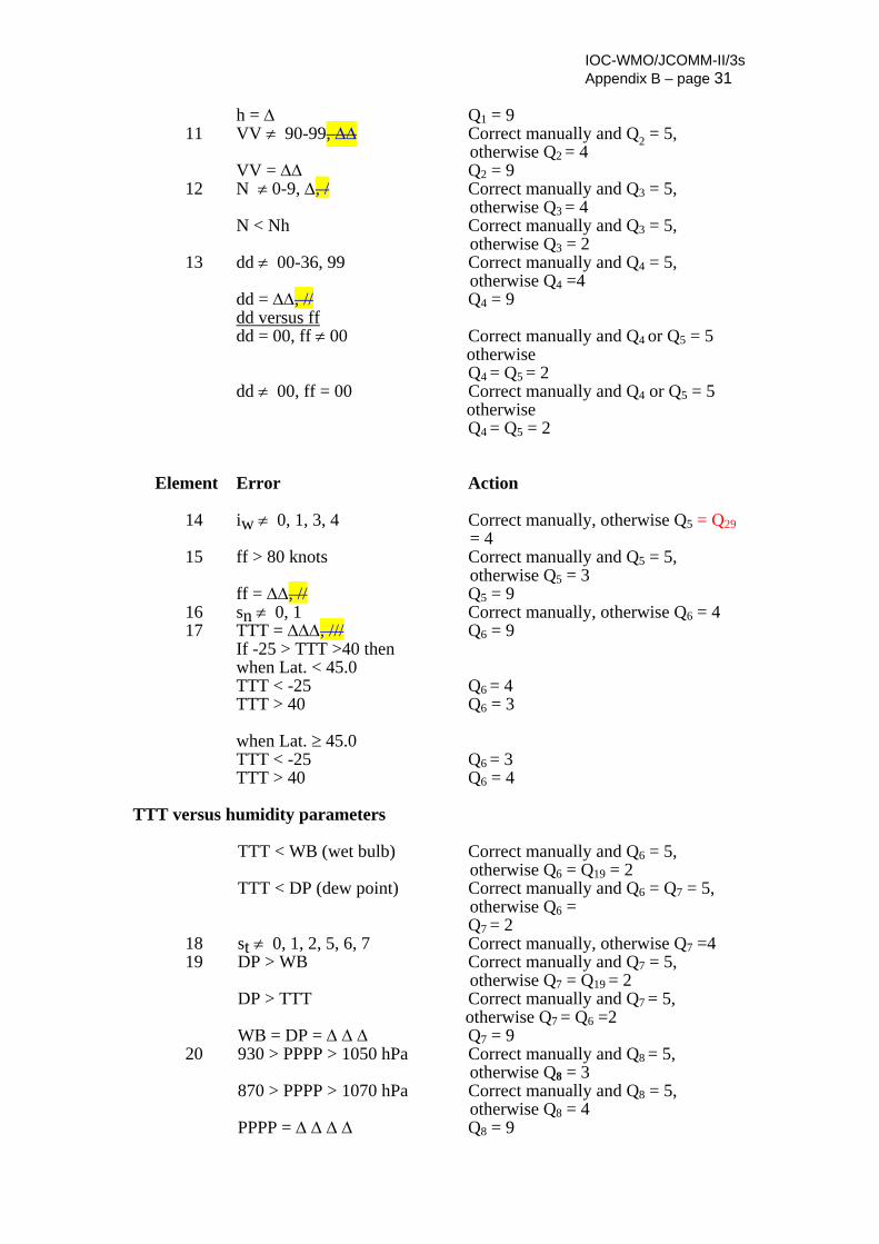
IOC-WMO/JCOMM-II/3s Appendix B – page 31
h = Δ Q1 = 9 11 VV ≠ 90-99, ΔΔ Correct manually and Q2 = 5, otherwise Q2 = 4 VV = ΔΔ Q2 = 9 12 N ≠ 0-9, Δ, / Correct manually and Q3 = 5, otherwise Q3 = 4 N < Nh Correct manually and Q3 = 5, otherwise Q3 = 2 13 dd ≠ 00-36, 99 Correct manually and Q4 = 5, otherwise Q4 =4 dd = ΔΔ, // Q4 = 9 dd versus ff dd = 00, ff ≠ 00 Correct manually and Q4 or Q5 = 5 otherwise Q4 = Q5 = 2 dd ≠ 00, ff = 00 Correct manually and Q4 or Q5 = 5 otherwise Q4 = Q5 = 2 Element Error Action 14 iw ≠ 0, 1, 3, 4 Correct manually, otherwise Q5 = Q29 = 4 15 ff > 80 knots Correct manually and Q5 = 5, otherwise Q5 = 3 ff = ΔΔ, // Q5 = 9 16 sn ≠ 0, 1 Correct manually, otherwise Q6 = 4 17 TTT = ΔΔΔ, /// Q6 = 9 If -25 > TTT >40 then when Lat. < 45.0 TTT < -25 Q6 = 4 TTT > 40 Q6 = 3 when Lat. ≥ 45.0 TTT < -25 Q6 = 3 TTT > 40 Q6 = 4 TTT versus humidity parameters
TTT < WB (wet bulb) Correct manually and Q6 = 5, otherwise Q6 = Q19 = 2 TTT < DP (dew point) Correct manually and Q6 = Q7 = 5, otherwise Q6 = Q7 = 2
18 st ≠ 0, 1, 2, 5, 6, 7 Correct manually, otherwise Q7 =4 19 DP > WB Correct manually and Q7 = 5, otherwise Q7 = Q19 = 2 DP > TTT Correct manually and Q7 = 5, otherwise Q7 = Q6 =2 WB = DP = Δ Δ Δ Q7 = 9 20 930 > PPPP > 1050 hPa Correct manually and Q8 = 5, otherwise Q8 = 3 870 > PPPP > 1070 hPa Correct manually and Q8 = 5, otherwise Q8 = 4 PPPP = Δ Δ Δ Δ Q8 = 9
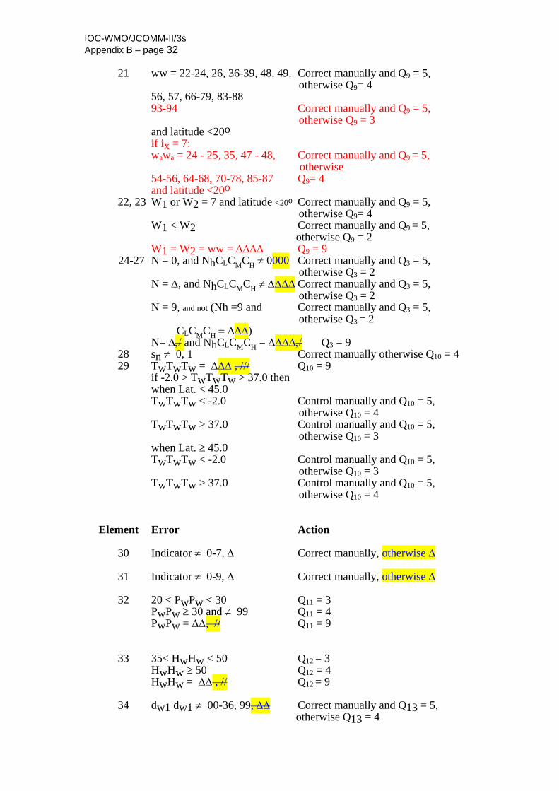
IOC-WMO/JCOMM-II/3s Appendix B – page 32 21 ww = 22-24, 26, 36-39, 48, 49, Correct manually and Q9 = 5, otherwise Q9= 4 56, 57, 66-79, 83-88 93-94 Correct manually and Q9 = 5, otherwise Q9 = 3 and latitude <20o if ix = 7: wawa = 24 - 25, 35, 47 - 48, Correct manually and Q9 = 5, otherwise 54-56, 64-68, 70-78, 85-87 Q9= 4 and latitude <20o 22, 23 W1 or W2 = 7 and latitude <20o Correct manually and Q9 = 5,
otherwise Q9= 4 W1 < W2 Correct manually and Q9 = 5, otherwise Q9 = 2 W1 = W2 = ww = ΔΔΔΔ Q9 = 9 24-27 N = 0, and NhCLCMCH ≠ 0000 Correct manually and Q3 = 5, otherwise Q3 = 2 N = Δ, and NhCLCMCH ≠ ΔΔΔΔ Correct manually and Q3 = 5, otherwise Q3 = 2 N = 9, and not (Nh =9 and Correct manually and Q3 = 5, otherwise Q3 = 2 CLCMCH = ΔΔΔ) N= Δ,/ and NhCLCMCH = ΔΔΔΔ,/ Q3 = 9
28 sn ≠ 0, 1 Correct manually otherwise Q10 = 4 29 TwTwTw = ΔΔΔ , /// Q10 = 9
if -2.0 > TwTwTw > 37.0 then when Lat. < 45.0 TwTwTw < -2.0 Control manually and Q10 = 5, otherwise Q10 = 4 TwTwTw > 37.0 Control manually and Q10 = 5, otherwise Q10 = 3 when Lat. ≥ 45.0 TwTwTw < -2.0 Control manually and Q10 = 5, otherwise Q10 = 3 TwTwTw > 37.0 Control manually and Q10 = 5, otherwise Q10 = 4
Element Error Action 30 Indicator ≠ 0-7, Δ Correct manually, otherwise Δ 31 Indicator ≠ 0-9, Δ Correct manually, otherwise Δ 32 20 < PwPw < 30 Q11 = 3 PwPw ≥ 30 and ≠ 99 Q11 = 4 PwPw = ΔΔ, // Q11 = 9 33 35< HwHw < 50 Q12 = 3 HwHw ≥ 50 Q12 = 4 HwHw = ΔΔ , // Q12 = 9 34 dw1 dw1 ≠ 00-36, 99, ΔΔ Correct manually and Q13 = 5, otherwise Q13 = 4
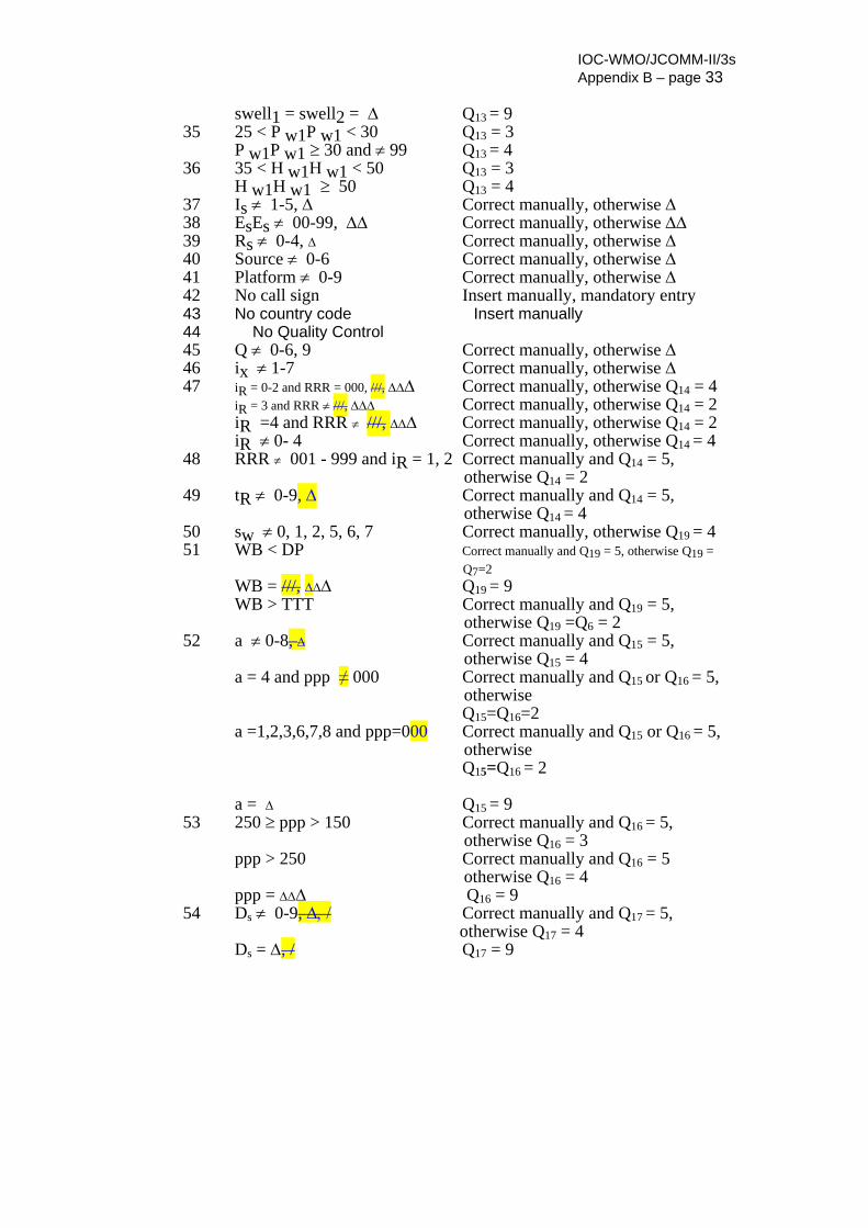
IOC-WMO/JCOMM-II/3s Appendix B – page 33
swell1 = swell2 = Δ Q13 = 9 35 25 < P w1P w1 < 30 Q13 = 3 P w1P w1 ≥ 30 and ≠ 99 Q13 = 4 36 35 < H w1H w1 < 50 Q13 = 3 H w1H w1 ≥ 50 Q13 = 4 37 Is ≠ 1-5, Δ Correct manually, otherwise Δ 38 EsEs ≠ 00-99, ΔΔ Correct manually, otherwise ΔΔ 39 Rs ≠ 0-4, Δ Correct manually, otherwise Δ 40 Source ≠ 0-6 Correct manually, otherwise Δ 41 Platform ≠ 0-9 Correct manually, otherwise Δ 42 No call sign Insert manually, mandatory entry 43 No country code Insert manually 44 No Quality Control 45 Q ≠ 0-6, 9 Correct manually, otherwise Δ 46 ix ≠ 1-7 Correct manually, otherwise Δ 47 iR = 0-2 and RRR = 000, ///, ΔΔΔ Correct manually, otherwise Q14 = 4 iR = 3 and RRR ≠ ///, ΔΔΔ Correct manually, otherwise Q14 = 2 iR =4 and RRR ≠ ///, ΔΔΔ Correct manually, otherwise Q14 = 2 iR ≠ 0- 4 Correct manually, otherwise Q14 = 4 48 RRR ≠ 001 - 999 and iR = 1, 2 Correct manually and Q14 = 5, otherwise Q14 = 2 49 tR ≠ 0-9, Δ Correct manually and Q14 = 5, otherwise Q14 = 4 50 sw ≠ 0, 1, 2, 5, 6, 7 Correct manually, otherwise Q19 = 4 51 WB < DP Correct manually and Q19 = 5, otherwise Q19 = Q7=2 WB = ///, ΔΔΔ Q19 = 9 WB > TTT Correct manually and Q19 = 5, otherwise Q19 =Q6 = 2 52 a ≠ 0-8, Δ Correct manually and Q15 = 5, otherwise Q15 = 4 a = 4 and ppp ≠ 000 Correct manually and Q15 or Q16 = 5, otherwise Q15=Q16=2 a =1,2,3,6,7,8 and ppp=000 Correct manually and Q15 or Q16 = 5, otherwise Q15=Q16 = 2 a = Δ Q15 = 9 53 250 ≥ ppp > 150 Correct manually and Q16 = 5, otherwise Q16 = 3 ppp > 250 Correct manually and Q16 = 5 otherwise Q16 = 4 ppp = ΔΔΔ Q16 = 9 54 Ds ≠ 0-9, Δ, / Correct manually and Q17 = 5, otherwise Q17 = 4 Ds = Δ, / Q17 = 9
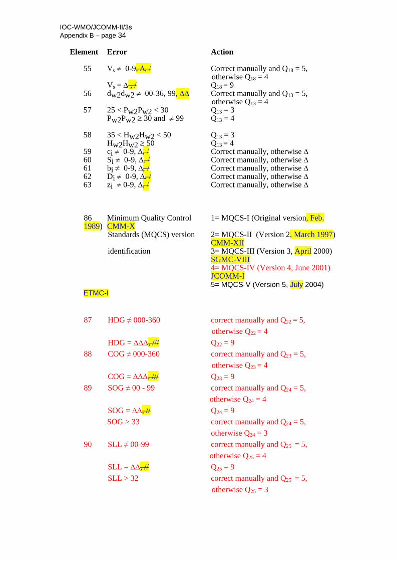
IOC-WMO/JCOMM-II/3s Appendix B – page 34 Element Error Action 55 Vs ≠ 0-9, Δ, / Correct manually and Q18 = 5, otherwise Q18 = 4 Vs = Δ , / Q18 = 9 56 dw2dw2 ≠ 00-36, 99, ΔΔ Correct manually and Q13 = 5, otherwise Q13 = 4 57 25 < Pw2Pw2 < 30 Q13 = 3 Pw2Pw2 ≥ 30 and ≠ 99 Q13 = 4 58 35 < Hw2Hw2 < 50 Q13 = 3 Hw2Hw2 ≥ 50 Q13 = 4 59 ci ≠ 0-9, Δ, / Correct manually, otherwise Δ 60 Si ≠ 0-9, Δ, / Correct manually, otherwise Δ 61 bi ≠ 0-9, Δ, / Correct manually, otherwise Δ 62 Di ≠ 0-9, Δ, / Correct manually, otherwise Δ 63 zi ≠ 0-9, Δ, / Correct manually, otherwise Δ
86 Minimum Quality Control 1= MQCS-I (Original version, Feb. 1989) CMM-X
Standards (MQCS) version 2= MQCS-II (Version 2, March 1997) CMM-XII identification 3= MQCS-III (Version 3, April 2000) SGMC-VIII 4= MQCS-IV (Version 4, June 2001) JCOMM-I
5= MQCS-V (Version 5, July 2004) ETMC-I
87 HDG ≠ 000-360 correct manually and Q22 = 5, otherwise Q22 = 4 HDG = ΔΔΔ, /// Q22 = 9
88 COG ≠ 000-360 correct manually and Q23 = 5, otherwise Q23 = 4 COG = ΔΔΔ, /// Q23 = 9
89 SOG ≠ 00 - 99 correct manually and Q24 = 5, otherwise Q24 = 4 SOG = ΔΔ, // Q24 = 9 SOG > 33 correct manually and Q24 = 5,
otherwise Q24 = 3 90 SLL ≠ 00-99 correct manually and Q25 = 5,
otherwise Q25 = 4 SLL = ΔΔ, // Q25 = 9 SLL > 32 correct manually and Q25 = 5, otherwise Q25 = 3
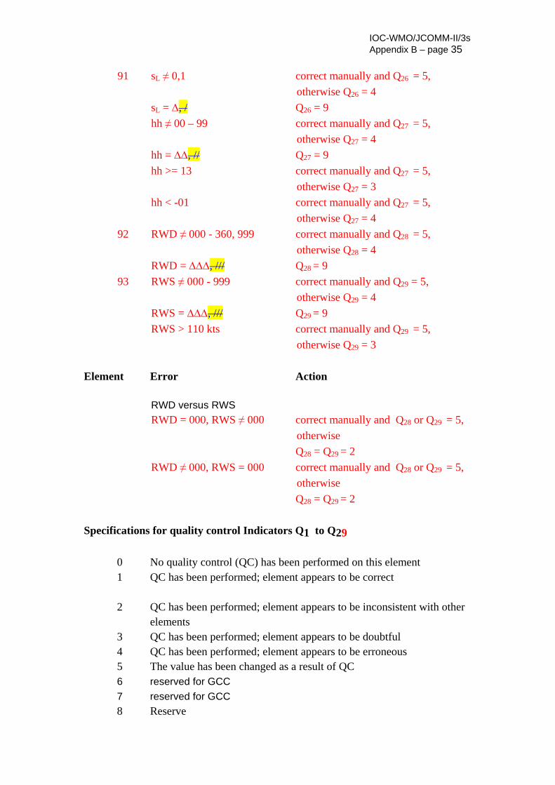
IOC-WMO/JCOMM-II/3s Appendix B – page 35
91 sL ≠ 0,1 correct manually and Q26 = 5,
otherwise Q26 = 4 sL = Δ, / Q26 = 9 hh ≠ 00 – 99 correct manually and Q27 = 5, otherwise Q27 = 4 hh = ΔΔ, // Q27 = 9 hh >= 13 correct manually and Q27 = 5, otherwise Q27 = 3 hh < -01 correct manually and Q27 = 5, otherwise Q27 = 4
92 RWD ≠ 000 - 360, 999 correct manually and Q28 = 5, otherwise Q28 = 4 RWD = ΔΔΔ, /// Q28 = 9
93 RWS ≠ 000 - 999 correct manually and Q29 = 5, otherwise Q29 = 4 RWS = ΔΔΔ, /// Q29 = 9 RWS > 110 kts correct manually and Q29 = 5,
otherwise Q29 = 3
Element Error Action RWD versus RWS
RWD = 000, RWS ≠ 000 correct manually and Q28 or Q29 = 5, otherwise Q28 = Q29 = 2 RWD ≠ 000, RWS = 000 correct manually and Q28 or Q29 = 5, otherwise Q28 = Q29 = 2
Specifications for quality control Indicators Q1 to Q29
0 No quality control (QC) has been performed on this element 1 QC has been performed; element appears to be correct 2 QC has been performed; element appears to be inconsistent with other
elements 3 QC has been performed; element appears to be doubtful 4 QC has been performed; element appears to be erroneous 5 The value has been changed as a result of QC 6 reserved for GCC 7 reserved for GCC 8 Reserve

IOC-WMO/JCOMM-II/3s Appendix B – page 36
9 The value of the element is missing

Appendix C _______________________________________________________ Wiring Diagrams
VAISALA ______________________________________________________________________ 217
APPENDIX C
WIRING DIAGRAMS
This chapter provides the default wiring diagrams for the most common sensor options used in MAWS410.
NOTE If system-specific wiring diagrams are delivered with the product, those will override the wiring diagrams presented here.
The wiring diagrams listed in Table 73 below are presented in the following pages.
Table 73 MAWS410 Wiring Diagrams Drawing Drawing Number MAWS410 main wiring diagram (1) DRW225490, sheet 1 MAWS410 main wiring diagram (2) DRW225490, sheet 2 WS425 Connection to MAWS410 (RS-485) DRW227449 QCO201 connection to MAWS410 (RS-232) DRW227469 DTS12W connection to MAWS410 DRW227455 QMH102 connection to MAWS410 DRW227452 WAC151 connection to MAWS410 DRW228467 GPS17-HVS connection to MAWS410 DRW228469

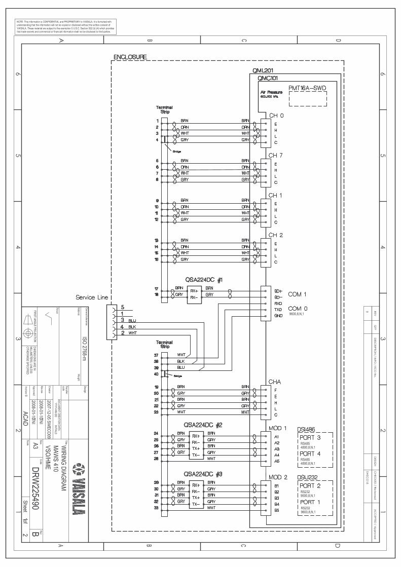

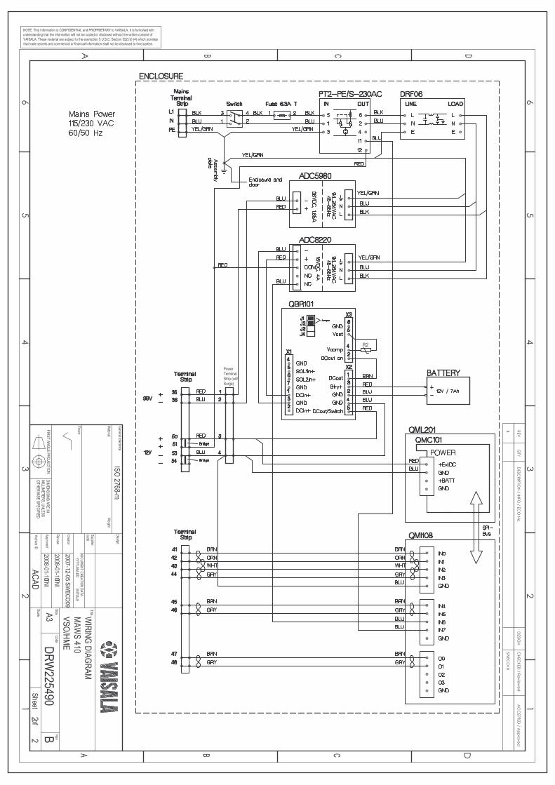

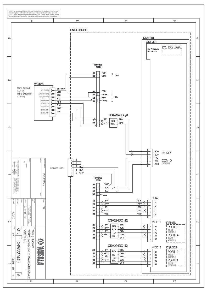

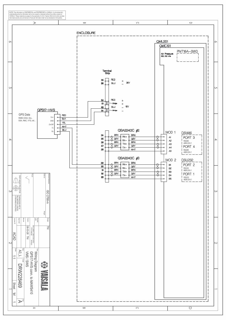

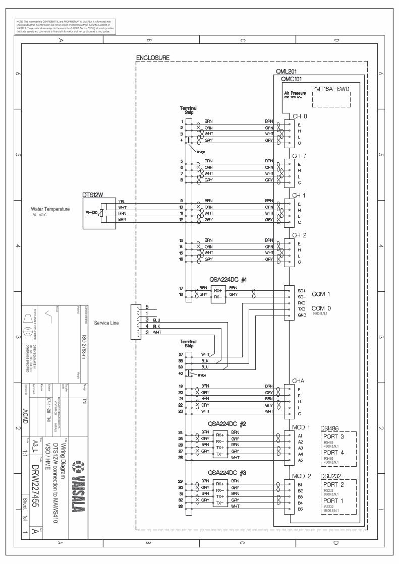

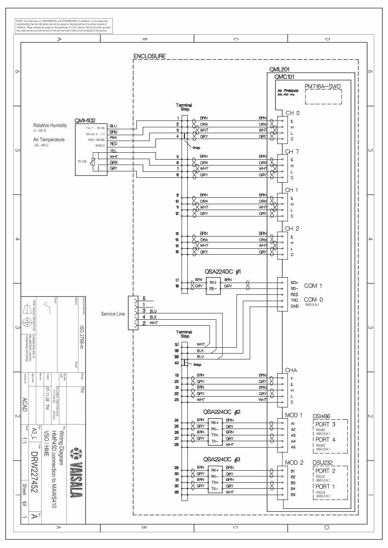

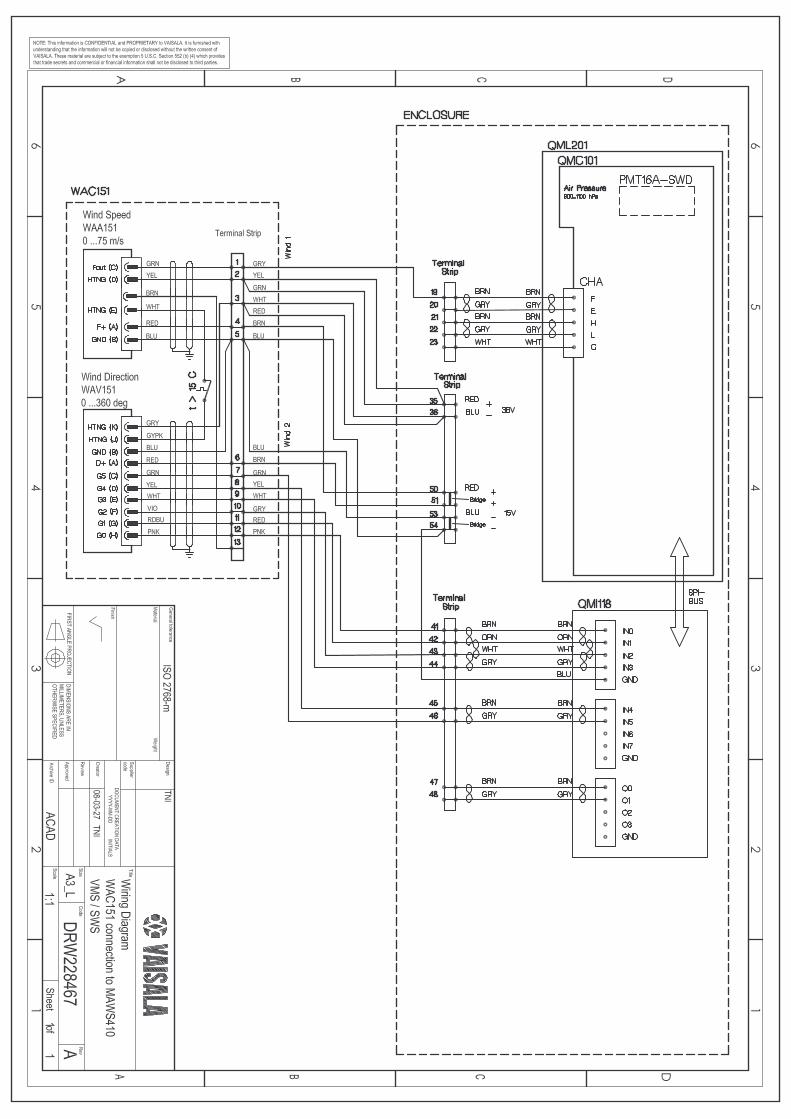

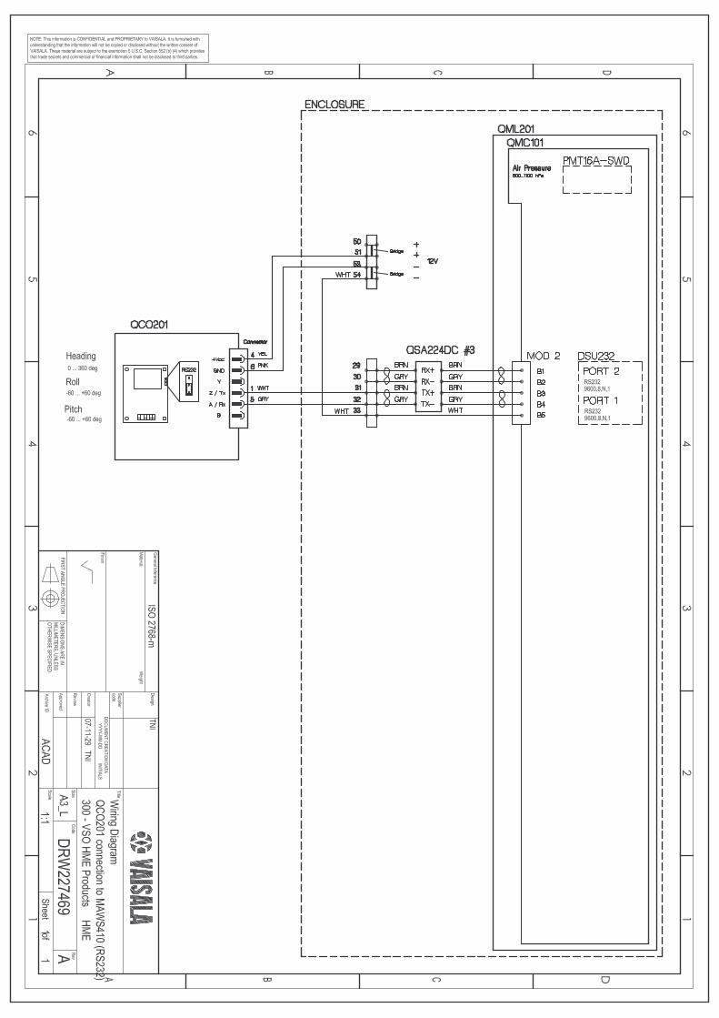

www.vaisala.com