
MAVOWATT 45 Energy and Power Disturbance …...MAVOWATT 45 Energy and Power Disturbance Analyzer 2...
12
MAVOWATT 45 Energy and Power Disturbance Analyzer 3-348-795-03 6/7.00 GOSSEN-METRAWATT GMBH 1 Use and Applications The portable MAVOWATT 45 Energy and Power Disturbance Analyzer has been designed for the measurement of electrical quantities in DC systems, as well as single and 3-phase AC systems with balanced or unbalanced loads with frequencies of up to 400 Hz. Measurements at frequency converter outputs (motor speed drives) are also possible with the TCM option. Applications range from acquisition, display and recording of mains quantities through the recognition and analysis of fluctu- ations and other interferences within the power supply (optional harmonic analysis, power disturbance and flicker analysis), right on up to analysis and recording of energy consumption. The Energy Analyzer can also be used for a wide variety of industrial applications. For example, it functions as a precision recorder and measuring instrument for the determination of characteristic quantities for electrical load components or generators either under static conditions or during dynamic operation. With the FFT option, it functions as a test instrument and compares harmonic current from load components with predefined limit values. Thanks to its compact and rugged design, the MAVOWATT 45 is not restricted to stationary operation, but can also be used for mobile applications. Included Basic Functions Measuring Contemporary acquisition of three analog voltage and three analog current signals with simultaneous sampling at 50 kHz Simultaneous acquisition of three digital pulse signals Calculation Calculation of derived electrical quantities for single and three- phase systems as instantanuous (RMS) values in minimum cycles of 1s, as well as extreme values and mean values within adjustable interval (minimum 2 s): – phase-to-neutral and phase-to-phase voltages, – phase currents and neutral current, – active, apparent and reactive power and energy, – power demand, power factor and crest factor, frequency Displays Numeric and graphic display of measured and calculated quantities in predefined combinations (selector switch positions L1, L2, L3, Y, , E and P), or in freely selectable combinations (SEL1, SEL2, SEL3, SEL4) with up to 20 variables Display of setup menus in various languages Display of operating and connecting instructions Monitoring Acquisition of violated limit values (user adjustable) for four selectable measured quantities. Limit violation is indicated with a group alarm by switching a floating relay contact and triggers a print-out of the respective measured values on the optional printer module. Registration and Documentation The measurement data can be printed on a paper strip with the optional printer module (accessory SECUTEST PSI), stored to a plug-in PCMCIA flash memory card (accessory Memory Card), transmitted via the RS232 interface to a PC running the Win- dows software METRAwin ® 45 (accessory) for presentation, analysis, documentation or export of the data to other programs. Options The instrument can be equipped with the following optional functions (for description see following pages): MAVO-FFT – Harmonic Analysis MAVO-PDA – Power Disturbance Analysis MAVO-TCM – Transient and Converter Measurements MAVO-FSA – Flicker Analysis Options are installed by the user with the help of a PC by uploading and enabling the specific device software via the included RS232 interface. Subsequent uploading of optional functions can be performed at any time.
Transcript of MAVOWATT 45 Energy and Power Disturbance …...MAVOWATT 45 Energy and Power Disturbance Analyzer 2...

MAVOWATT�45Energy and Power Disturbance Analyzer 3-348-795-03
6/7.00
GOSSEN-METRAWATT GMBH 1
Use and ApplicationsThe portable MAVOWATT 45 Energy and Power DisturbanceAnalyzer has been designed for the measurement of electricalquantities in DC systems, as well as single and 3-phase ACsystems with balanced or unbalanced loads with frequencies ofup to 400 Hz. Measurements at frequency converter outputs(motor speed drives) are also possible with the TCM option.Applications range from acquisition, display and recording ofmains quantities through the recognition and analysis of fluctu-ations and other interferences within the power supply (optionalharmonic analysis, power disturbance and flicker analysis), righton up to analysis and recording of energy consumption.The Energy Analyzer can also be used for a wide variety ofindustrial applications. For example, it functions as a precisionrecorder and measuring instrument for the determination ofcharacteristic quantities for electrical load components orgenerators either under static conditions or during dynamicoperation. With the FFT option, it functions as a test instrumentand compares harmonic current from load components withpredefined limit values.Thanks to its compact and rugged design, the MAVOWATT 45 isnot restricted to stationary operation, but can also be used formobile applications.
Included Basic FunctionsMeasuring� Contemporary acquisition of three analog voltage and three
analog current signals with simultaneous sampling at 50 kHz� Simultaneous acquisition of three digital pulse signalsCalculation� Calculation of derived electrical quantities for single and three-
phase systems as instantanuous (RMS) values in minimumcycles of 1s, as well as extreme values and mean valueswithin adjustable interval (minimum 2 s):– phase-to-neutral and phase-to-phase voltages,– phase currents and neutral current,– active, apparent and reactive power and energy,– power demand, power factor and crest factor, frequency
Displays� Numeric and graphic display of measured and calculated
quantities in predefined combinations (selector switch positionsL1, L2, L3, Y, �, E and P), or in freely selectable combinations(SEL1, SEL2, SEL3, SEL4) with up to 20 variables
� Display of setup menus in various languages� Display of operating and connecting instructionsMonitoring� Acquisition of violated limit values (user adjustable) for four
selectable measured quantities. Limit violation is indicated witha group alarm by switching a floating relay contact and triggersa print-out of the respective measured values on the optionalprinter module.
Registration and DocumentationThe measurement data can be� printed on a paper strip with the optional printer module
(accessory SECUTEST PSI),� stored to a plug-in PCMCIA flash memory card (accessory
Memory Card),� transmitted via the RS232 interface to a PC running the Win-
dows software METRAwin®45 (accessory) for presentation,analysis, documentation or export of the data to other programs.
Options The instrument can be equipped with the following optionalfunctions (for description see following pages):� MAVO-FFT – Harmonic Analysis� MAVO-PDA – Power Disturbance Analysis� MAVO-TCM – Transient and Converter Measurements� MAVO-FSA – Flicker AnalysisOptions are installed by the user with the help of a PC byuploading and enabling the specific device software via theincluded RS232 interface. Subsequent uploading of optionalfunctions can be performed at any time.

MAVOWATT�45Energy and Power Disturbance Analyzer
2 GOSSEN-METRAWATT GMBH
GeneralPower SupplyFor auxiliary power supply the MAVOWATT 45 requires 230Vacor 115Vac line voltage.If the instrument is to be used for power disturbance analysis ofits own power supply, and if power failures >30ms are expectedto occur, a commercially available uninterruptible power supply(UPS) or the one being offered as accessory can be utilized.
Isolated Measurement InputsThe MAVOWATT 45 has the following measurement inputs:� Three analog voltage measurement inputs UL1, UL2, UL3 for direct or
alternating voltages of up to 600 V (for overvoltage categoryCAT IV) or 1000 V (CAT III). Measurements in medium-highvoltage systems must generally be performed via voltagetransformers at the system side! The correspondingtransformation ratio, Uratio, can be selected individually foreach input.The 2-pole, floating inputs are electrically isolated from oneanother.
� Three analog current measurement inputs IL1, IL2, IL3 set up asvoltage inputs (see Technical Data for measuring ranges) forthe connection of shunts or (clip-on) current transformers withvoltage output, or burdened current transformers. The corres-ponding transformation ratio, Iratio, can be selected individuallyfor each input.The 2-pole, floating inputs are electrically isolated from oneanother.
� Three digital counter inputs Dig.-In. P4, P5, P6 for the determina-tion of energy and power demand quantities through the use ofinterconnected pulse generators (usually meters with pulseoutputs). The corresponding counter constant, cconst, can beselected individually for each input.The 2-pole, floating inputs (S0 compatible, max. 48 V) arefunctionally isolated from one another.
The SYNC. input enables synchronization of the two measuringtime periods, interval (for determination of general minima,maxima and average values) and period, (aggregation timeinterval for demand power) to the clock pulse of the electricitysupplier.
Simultaneous Signal ProcessingThe applied measurement signals run via internal voltage devi-ders to 16 bit A/D-converters. Signal conversion and processingis executed individually for each phase channel in real-time. Bymeans of this simultaneous measurement an exact registrationof the phase relation in a three-phase power system is achieved.The measuring principle is a waveform independent true r.m.s.(TRMS) measurement.Each A/D-converter is coupled to a Digital Signal Processor(DSP) which calculates the values of the requested measure-ment quantities and transmits the results via opto-couplers withhigh insulation to the MAIN CPU. This processor controls allactivities of acquisition, processing and presentation of themeasured signals as well as inputs from the operating elementsand outputs to LC Display, PC card and serial RS232 interface(printer module, PC).
Alphanumeric and Graphic DisplayThe illuminated LC dot-matrix displaynot only shows measurement results,status informations and setup menues,but also operating and connectinginstructions. For the representation ofmeasured values, series measurementsand analyses at the LCD variousdisplay formats are available.
Multilingual Menu-Driven OperationMeasured quantities and functions are selected with the functionselector rotary-switch. By means of four pushbuttons the menu-driven selection and adjustment of display formats, operatingmodes, parameters and functions is made. The fifth key, i, isused to query a directory which contains information concerningthe current selector switch position.For the language of the setup menus a choice can be madebetween two options (German/English as standard) Otherlanguage versions (French, Italian, Spanish, Dutch) are availableas software modules on a diskette supplied with the instrumentand can be uploaded into the device from a PC via its serial port.Measuring and instrument parameter settings remain intact,even after the instrument has been switched off.High application safety is achieved and faulty operation is largelyexcluded due to the galvanic isolation of the three phasechannels and the auto-ranging measurement inputs.
Storage of Measurements� As standard the MAVOWATT 45 contains a volatile RAM as
operating memory (FIFO register) for approx. 900 measuredvalues of the selected quantities including time stamp. Thecontent of the register can be displayed in tabular form or as aY-t graph and provides the basis for statistical analysis.
� A non-volatile image memory stores up to 15 „screen-shots“which can be recalled into the display with the „REPlayHardcopy“ function.
� The measuring results of all analysis functions can be stored tonon-volatile measurement data memory with the plug-in PC cardbeing available as accessory Memory Card (PCMCIA flashmemory card; AMD Series C; memory density: approx.250.000 meas. values/MByte).Measurement data of up to 20 quantities of power/energyanalysis will be stored as MIN/MAX/AVR or present value withselectable interval in tabular format with date and time. Data ofFFT, FSA, PDA and Transient measurements are stored in thechosen display format. Recorded data can be displayed at theLCD but for analysis of long-time recordings the use of soft-ware METRAwin®45 is recommended.
Printing The following printing features are madepossible with the optional SECUTESTPSI printer module:� Manually triggered print-out of the current
LC display;� Time controlled print-out (interval printing)
of respective measurement values atthe end of a selected time period;
� Measurement value driven print-out (alarmprinting) of measurement values for upto four selectable quantities dependentupon individually adjustable limit values.

MAVOWATT�45Energy and Power Disturbance Analyzer
GOSSEN-METRAWATT GMBH 3
Power and Energy AnalysisAvailable Measured QuantitiesSwitch positions with preprogrammed measured quantities areavailable for measurements within individual phases (L1, L2, L3)and within the overall system (wye or delta) as well as for energyand power demand analysis (E, P).Up to 20 measured quantities can be assigned to each of theselector switch positions SEL1 through SEL4 in any desired order.In total 75 different measured quantities are offered:FormulaChar.
Quantity Unit ofMeas.
AssignableMeas. Type
U1 L1 phase-to-neutral voltage V � � �
U2 L2 phase-to-neutral voltage V � � �
U3 L3 phase-to-neutral voltage V � � �
U� Equivalent 3-phase wye voltage V � � �
I1 L1 phase current A � � �
I2 L2 phase current A � � �
I3 L3 phase current A � � �
I� 3-phase total current A � � �
In Neutral conductor current A � � �
U12 L1-2 phase-to-phase voltage V � � �
U23 L2-3 phase-to-phase voltage V � � �
U31 L3-1 phase-to-phase voltage V � � �
P1 L1 active power W � � � 0 1P2 L2 active power W � � � 0 1P3 L3 active power W � � � 0 1P� 3-phase total active power W � � � 0 1P4 Active power at digital counter input 4 W � � � 0 1P5 Active power at digital counter input 5 W � � � 0 1P6 Active power at digital counter input 6 W � � � 0 1Pc� Total active power at digital counter inputs
4+5+6W � � � 0 1
Q1 L1 reactive power var � � � 0 1Q2 L2 reactive power var � � � 0 1Q3 L3 reactive power var � � � 0 1Q� 3-phase total reactive power var � � � 0 1Qc Reactive power at digital counter input 4 var � � � 0 1S1 Apparent power at L1 VA � � � 0 1S2 Apparent power at L2 VA � � � 0 1S3 Apparent power at L3 VA � � � 0 1S� 3-phase total apparent power VA � � � 0 1DQ1 Required compensating reactive power at
L1 to attain preset power factor PFnomvar � � � 0 1
DQ2 Required compensating reactive power atL2 to attain preset power factor PFnom
var � � � 0 1
DQ3 Required compensating reactive power atL3 to attain preset power factor PFnom
var � � � 0 1
DQ� Required total compensating reactive powerto attain preset power factor PFnom
var � � � 0 1
WP1 Active energy at L1 Wh 0 1WP2 Active energy at L2 Wh 0 1WP3 Active energy at L3 Wh 0 1WP� Total active energy in 3-phase system Wh 0 1WQ1 Reactive energy at L1 varh 0 1WQ2 Reactive energy at L2 varh 0 1WQ3 Reactive energy at L3 varh 0 1WQ� Total reactive energy in 3-phase system varh 0 1
WS1 Apparent energy at L1 VAh 0 1WS2 Apparent energy at L2 VAh 0 1WS3 Apparent energy at L3 VAh 0 1WS� Total apparent energy in 3-phase system VAh 0 1W4 Active, apparent or reactive energy at counter
input 4 (depending upon type ofinterconnected impulsing meter)
VAh 0 1
W5 Active, apparent or reactive energy at counterinput 5
VAh 0 1
W6 Active, apparent or reactive energy at counterinput 6
VAh 0 1
WPT1 Total active energy cumulative for tariff zone 1 Wh 0 1WPT2 Total active energy cumulative for tariff zone 2 Wh 0 1WPT3 Total active energy cumulative for tariff zone 3 Wh 0 1W4T1 Active, apparent or reactive energy at counter
input 4, cumulative for tariff zone 1VAh 0 1
W4T2 Active, apparent or reactive energy at counterinput 4, cumulative for tariff zone 2
VAh 0 1
W4T3 Active, apparent or reactive energy at counterinput 4, cumulative for tariff zone 3
VAh 0 1
W5T1 Active, apparent or reactive energy at counterinput 5, cumulative for tariff zone 1
VAh 0 1
W5T2 Active, apparent or reactive energy at counterinput 5, cumulative for tariff zone 2
VAh 0 1
W5T3 Active, apparent or reactive energy at counterinput 5, cumulative for tariff zone 3
VAh 0 1
W6T1 Active, apparent or reactive energy at counterinput 6, cumulative for tariff zone 1
VAh 0 1
W6T2 Active, apparent or reactive energy at counterinput 6, cumulative for tariff zone 2
VAh 0 1
W6T3 Active, apparent or reactive energy at counterinput 6, cumulative for tariff zone 3
VAh 0 1
PF1 Power factor at L1 cap./ind. � � �
PF2 Power factor at L2 cap./ind. � � �
PF3 Power factor at L3 cap./ind. � � �
PF� Power factor for the 3-phase system cap./ind. � � �
PFc Power factor derived from counter inputs 4(Q) and 5 (P)
cap./ind. � � �
cu1 Crest factor of voltage U1 – � � �
cu2 Crest factor of voltage U2 – � � �
cu3 Crest factor of voltage U3 – � � �
cu� Mean crest factor of voltages U1, U2, U3 – � � �
f Frequency of voltage U1 Hz � � �
ci1 Crest factor of current I1 – � � �
ci2 Crest factor of current I2 – � � �
ci3 Crest factor of current I3 – � � �
ci� Mean crest factor of currents I1, I2, I3 – � � �
Rot Phase sequence (rotation sense) for allvoltages in the 3-phase system
> / <
Individually for each selected quantity its evaluation can beperformed in different Measurement Types:– = Instantaneous: (RMS) value at present
(acquired once per refresh cycle (minimum 1s) from an integral over 20 signal cycles),
� = MAX: Highest instantaneous value within adjustable interval (2 ...1800s),
� = MIN: Lowest instantaneous value within adjustable interval,� = AVR: Arithmetic mean value within adjustable interval,0 = Period 0: Arithmetic mean value within currently running
adjustable period,1 = Period 1: Arithmetic mean value within last completed
adjustable period.

MAVOWATT�45Energy and Power Disturbance Analyzer
4 GOSSEN-METRAWATT GMBH
Representation of Measurement Values and Series MeasurementsVarious display formats are available for the representation ofmeasurement values, series measurements and analysis at theLCD.
The numeric display format presents thecurrently measured values simultane-ously for up to ten quantities as 4-digitnumbers with floating decimal point, unitof measure and with polarity indication.Evaluation is made considering the indi-vidually adjustable transmission ratios forthe connected current and voltagetransformers.
With bar-graph display mode the currentlymeasured values for up to four quantitiesare displayed as horizontal bars.Scaling is performed automatically in dis-crete ranges. In addition to the bar graph,the respective measurement values andranges are also displayed numerically.
Numeric display of measurement valuescontained in the FIFO register for ameasured quantity as a table includingmeasurement value and time.Logging the measured values into thetable and if being used also into memorycard takes place according to the settime interval.
Graphic display of measurement values inthe FIFO register for a given measuredquantity as a Y-t graph.For example when using an interval of900 s, then under SEL1 ...4 the 15minute average of a measurementquantity and/or ist min/max value(s)within each interval can be observed overa period of 23 hours.
The statistical distribution of the measure-ment values present in the FIFO registerare displayed over 9 classes (valueranges of eaqual span) simultaneouslyfor two measured quantities.The classes are defined automaticallybetween the lowest and the highestregistered value.
Graphic display of the voltage and/orcurrent waveshape based upon thecurrently sampled values at therespective analog measurement input.Scaling of the Y and t axes is performedautomatically and indicates therespective signal peak amplitudes andthe cyle time.In this display mode also the distortionand phase shift of voltage and currentcan be recognized
Print-Out and Signalisation of Limit Value ViolationsUpper and lower limit value violations canbe printed out for four selectablemeasured quantitiesThe following are documented in theprint-out:– "Al" identifies the alarm condition,– Date and time,– The measurement values of the
monitored quantities when the alarmoccurred.
Violations of upper and/or lower limit values are also indicated bymeans of an alarm output (changeover contact) which functionsas a group interrupt.Alarm printing and signal response time correspond to the valuerefresh time of 1 s minimum. These functions are therefore notsuited for the documentation or signaling of very brief limit valueviolations. The MAVO-PDA and MAVO-TCM options areprovided for this purpose.
Evaluation of Power Consumption in Different Tariff ZonesTariffs established by the power utilitiesinclude a wide variety of tariff types withdifferent tariff zones. Tariffs for specialclients (i.e. large customers) furtherbroaden the range of tariff types.With the MAVOWATT 45 up to six timesof a day can be assigned to three tarifftypes for recording of the specific energyconsumption.
Evaluation of Peak Demand PowerAs a matter of principal evaluation of chargeable demand forbilling purposes is different to measurements in other fields ofmains power metrology.Therefore a second measuring interval (demand observationperiod) is available for power and energy measurements. Bothmeasuring intervals ("Interval" and "Period") can be usedsimultanuosly for evaluation of mains quantities with differentmeasurement types.Based on the accumulated energyconsumed within the set time period theperiodic power demand is calculated,saved and then reset. The load curveresults from the consecutive registrationof periodic power values. Usually the(three) highest periodic power valueswhich occur during given billing periodsare used by the power utilities forevaluation of the chargeable demand.The maximum or averaged power value within the set interval cansimultanuously be registered. This shows the highest short-termloading of the system for rating of the system components.Via a SYNC input both measurement intervals can besynchronized with the clock supplied by the power utility.

MAVOWATT�45Energy and Power Disturbance Analyzer
GOSSEN-METRAWATT GMBH 5
Harmonic Analysis (Option MAVO-FFT)The harmonic analysis option is used for simultaneous acquisition, displayand analysis of voltage and current harmonics up to the 50 th harmonic inpower supply systems with fundamental frequencies ranging from 15 to400Hz.Fast Fourier Transformation is used for continuous, uninterruptedacquisition and analysis of DC components, fundamentalfrequencies and harmonics by means of a 16 period rectangularwindow in real-time at all three phases. Various analysis anddisplay modes allow for quantitative and qualitative evaluationsof semi-stable, as well as fluctuating harmonics.
As a basic analysis, the measurementvalues for respective THD (total harmo-nic distortion) for all three phases canbe simultaneously displayed in numericformat for both voltage and current, orcan be statistically classified.
A detailed analysis can be displayed ineither graphic or tabular form.
The graphic representation shows thefrequency spectrum for harmonic contentas a bar graph.In addition to this, fundamental frequencymeasurement values, as well as one se-lectable harmonic or the DC componentare displayed numerically.
The tabular representation shows eitherfundamental frequency measurementvalues and the odd harmonics, or the DCcomponents and the even harmonics.Phase angles as related to the voltagefundamental, or the respectivepercentage value for harmonic contentcan also be displayed.
These displays appear for one selected phase only, althoughsimultaneous recording to a PC memory card is possible for allthree phases.Furthermore the MAVO-FFT option offers two test functions:� During non-gaping evaluation of the
voltage harmonics and comparison tothe limits of EN 50160 (Voltagecharacteristics of electricity supplied bypublic distribution systems) a counterregistrates the number of violationswithin an adjustable time interval.
� During non-gaping evaluation of thecurrent harmonics and comparison tothe limits of EN 61000-3-2 (Limits forharmonic current emissions of equip-ment with input current <16 A/phase) acounter registers the number ofviolations within an adjustable timeinterval.
Power Disturbance Analysis (Option MAVO-PDA)The MAVO- PDA option allows for the documentation of significant linevoltage characteristics as required by EN 50160 on the one hand, and, forexample, the analysis of dynamic parameters at load components as well.The MAVOWATT 45 makes use of Power Disturbance Analysismethods which allow for uninterrupted monitoring and classifi-cation of disturbances within electrical power supply networks.
The measured quantities (RMS valuesfor voltage and current, as well asfrequency and THD), which have beencalculated during 2, 4, 8 or 16 signalperiods for all, or only selected phases,are continuously compared with therespective, individually selected triggercriteria (upper limit for U/I/ THDU/THDI/f,lower limit for U/I//f, fluctuation for U/I).
Individually or simultaneously occurring events are continuouslyrecorded and are summarized for display in three differenttables:� Number and type of voltage and fre-
quency events which occurred withinan adjustable interval period;
� Number and type of current eventswhich occurred within an adjustableinterval period;
� Events list with indication of point intime, cause and measurement value.
If continuous acquisition is not required, voltage and currentsignal characteristics can be displayed with high time resolutionwhen an event occurs:

MAVOWATT�45Energy and Power Disturbance Analyzer
6 GOSSEN-METRAWATT GMBH
Transient and Converter Measurements (OptionMAVO-TCM)The MAVO-TCM option expands the scope of functions as well asthe applications possibilities for the MAVOWATT 45 through theinclusion of two special utilities for mains systems measurements:� On the one hand, this option allows for the logging of short, transient
events which occur in alternating or direct voltage systems, and at loadcomponents driven by such systems;
� On the other hand, the instrument is equipped with the capability ofascertaining the measurement quantities, which are included in thebasic functions for power and energy analysis also at the outputs offrequency converters.
The Measurement of TransientsThe MAVO-TCM option allows for logging of voltage and current transientswith a duration of at least 20 �s, and voltage levels of up to 1500 Vp.As opposed to the MAVO-PDA option with its RMS value triggercriteria, trigger parameters for the registration of line faults arebased upon sampled values when the TCM function is active.Level Triggers Up and Ip: The trigger is derived from a comparisonof the sampling value quantity and the set limit value.Slope Triggers dU/dt and dI/dt: The trigger results from acomparison of the rate of rise or fall of two consecutive sampledvalues and the set limit value (V/ms or A/ms).The time interval between two consecutive sampling operations,and thus the minimum duration of recognizable events, can beselected in six steps ranging from 20 �s to 648 �s.After an event has been recognized in theGraph display mode, approx. 3900 samplevalues (corresponds to 78 ms to 2.5 s ofrecording time) for current and voltage ofthe concerning phase are stored to memo-ry and displayed as a characteristic curvewith indication of the cause of triggeringunder consideration of the percentagevalue selected for the Pre-Trigger.In addition to the logging of sporadic line voltage faults, this typeof representation is also well suited for the recording of currentand voltage signal characteristics when load components areswitched on (e.g. motor start-up).
An Events list can be used for the recor-ding of rapid, consecutive trigger events.Up to approximately 40 events per se-cond are recorded in order of occurrencewith date, time, cause of triggering,measurement magnitude and sampled orslope measurement value.
Frequency Converter MeasurementsThe frequency converters which are currently used for the controlof electric motor speed are usually equipped with a high frequencysquare-wave output voltage which is pulse-width modulated bymeans of motor frequency. Measurement signals of this typerequire a special measuring process, by means of which theconverter operating frequency is filtered out, and which is capableof determining the effective modulation frequency (fundamentalfrequency) at the motor. The MAVOWATT 45 can derive all of thepower and energy analysis measurement magnitudes based onsignals which have been conditioned in this fashion.– The operating frequency must be greater than 1200 Hz andthe fundamental frequency must lie within a range of 10÷100Hz.;– For current sensing clip-on current transformers must be used.
Flicker Measurement (Option MAVO-FSA)The MAVO-FSA option expands the MAVOWATT 45 to include a flickermeter function.Flicker is defined as the subjective perception of brightness fluc-tuations at light fixtures caused by supply voltage fluctuations.Fluctuations of this type can be measured and analyzed with thehelp of a flicker meter. EN 61000-4-15 (former EN 60868)defines the basic functional principle of the flicker meter, whichsimulates via an appropriate algorithm functional transfer cha-racteristic of incandescent lamp � human eye � human brain.The flicker severity resulting from that serves as a measure forthe human perception of disturbance caused by fluctuation oflight intensity.
The values for the resulting measuredquantities Pst (10 min short-term flickerseverity) and Plt (2h long-term flicker se-verity) are simultaneously calculated forall three phases on an individual basis.An evaluation of mains voltage quality inaccordance with EN 50160 can be per-formed on the basis of these measure-
ment values.Additionally, thisfunction also allowsfor the acquisition ofthe largest relativechange in voltagedmax, relative constantvoltage deviation dcand the maximumduration of deviationdt>3% for voltagechanges of greaterthan 3% within theshort-term measuringinterval.These measured quantities are required for type testing for elec-trical devices in accordance with EN 61000-3-3. The observanceof the limit values set forth in this standard will be absolutelyessential for branding electrical equipment with rated current�16A with the CE mark as of 1 January 2001.
MAVOWATT�45Energy and Power Disturbance Analyzer
GOSSEN-METRAWATT GMBH 7
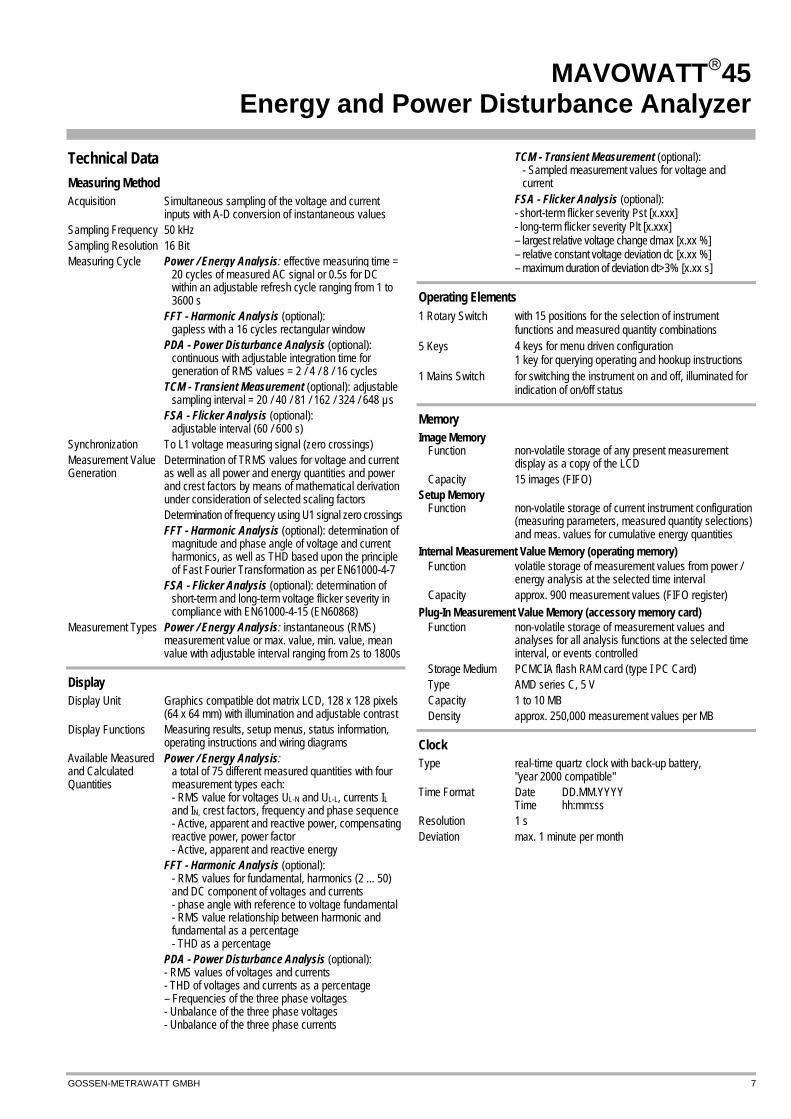
Technical DataMeasuring MethodAcquisition Simultaneous sampling of the voltage and current
inputs with A-D conversion of instantaneous valuesSampling Frequency 50 kHzSampling Resolution 16 BitMeasuring Cycle Power / Energy Analysis: effective measuring time =
20 cycles of measured AC signal or 0.5s for DCwithin an adjustable refresh cycle ranging from 1 to3600 s
FFT - Harmonic Analysis (optional):gapless with a 16 cycles rectangular window
PDA - Power Disturbance Analysis (optional):continuous with adjustable integration time forgeneration of RMS values = 2 / 4 / 8 / 16 cycles
TCM - Transient Measurement (optional): adjustablesampling interval = 20 / 40 / 81 / 162 / 324 / 648 µs
FSA - Flicker Analysis (optional):adjustable interval (60 / 600 s)
Synchronization To L1 voltage measuring signal (zero crossings)Measurement ValueGeneration
Determination of TRMS values for voltage and currentas well as all power and energy quantities and powerand crest factors by means of mathematical derivationunder consideration of selected scaling factorsDetermination of frequency using U1 signal zero crossingsFFT - Harmonic Analysis (optional): determination of
magnitude and phase angle of voltage and currentharmonics, as well as THD based upon the principleof Fast Fourier Transformation as per EN61000-4-7
FSA - Flicker Analysis (optional): determination ofshort-term and long-term voltage flicker severity incompliance with EN61000-4-15 (EN60868)
Measurement Types Power / Energy Analysis: instantaneous (RMS)measurement value or max. value, min. value, meanvalue with adjustable interval ranging from 2s to 1800s
DisplayDisplay Unit Graphics compatible dot matrix LCD, 128 x 128 pixels
(64 x 64 mm) with illumination and adjustable contrastDisplay Functions Measuring results, setup menus, status information,
operating instructions and wiring diagramsAvailable Measuredand CalculatedQuantities
Power / Energy Analysis:a total of 75 different measured quantities with fourmeasurement types each:- RMS value for voltages UL-N and UL-L, currents ILand IN, crest factors, frequency and phase sequence- Active, apparent and reactive power, compensatingreactive power, power factor- Active, apparent and reactive energy
FFT - Harmonic Analysis (optional):- RMS values for fundamental, harmonics (2 ... 50)and DC component of voltages and currents- phase angle with reference to voltage fundamental- RMS value relationship between harmonic andfundamental as a percentage- THD as a percentage
PDA - Power Disturbance Analysis (optional):- RMS values of voltages and currents- THD of voltages and currents as a percentage– Frequencies of the three phase voltages- Unbalance of the three phase voltages- Unbalance of the three phase currents
TCM - Transient Measurement (optional):- Sampled measurement values for voltage andcurrent
FSA - Flicker Analysis (optional):- short-term flicker severity Pst [x.xxx]- long-term flicker severity Plt [x.xxx]– largest relative voltage change dmax [x.xx %]– relative constant voltage deviation dc [x.xx %]– maximum duration of deviation dt>3% [x.xx s]
Operating Elements1 Rotary Switch with 15 positions for the selection of instrument
functions and measured quantity combinations5 Keys 4 keys for menu driven configuration
1 key for querying operating and hookup instructions1 Mains Switch for switching the instrument on and off, illuminated for
indication of on/off status
MemoryImage Memory
Function
Capacity
non-volatile storage of any present measurementdisplay as a copy of the LCD15 images (FIFO)
Setup MemoryFunction non-volatile storage of current instrument configuration
(measuring parameters, measured quantity selections)and meas. values for cumulative energy quantities
Internal Measurement Value Memory (operating memory)Function
Capacity
volatile storage of measurement values from power /energy analysis at the selected time intervalapprox. 900 measurement values (FIFO register)
Plug-In Measurement Value Memory (accessory memory card)Function
Storage MediumTypeCapacityDensity
non-volatile storage of measurement values andanalyses for all analysis functions at the selected timeinterval, or events controlledPCMCIA flash RAM card (type I PC Card)AMD series C, 5 V1 to 10 MBapprox. 250,000 measurement values per MB
ClockType
Time Format
ResolutionDeviation
real-time quartz clock with back-up battery,"year 2000 compatible"Date DD.MM.YYYYTime hh:mm:ss1 smax. 1 minute per month

MAVOWATT�45Energy and Power Disturbance Analyzer
8 GOSSEN-METRAWATT GMBH
Voltage Measurement InputsFunction Three 2-pole voltage inputs with automatic range selec-
tion and individually adjustable scaling factors for U/Utransformer, electrically isolated from one another(manual range selection for PDA, TCM, FSA functions)
Measuring Range Nominal Vrms 15 120 1000Range Limit Sine Vrms 14.5 138 1030
Peak/DC Vpk 21 195 1460
at Frequency ±(% of reading + mV•Uratio)MeasurementUncertainty 1) DC/15…65Hz 0.6%+5mV 0.2%+50mV 0.2%+0.3V
65…500 Hz 0.9%+5mV 0.3%+50mV 0.4%+0.3V0.5…2 kHz — 0.4%+50mV 0.8%+0.6V2…10 kHz — 2%+100mV 2%+1 V
Overload Capacity 1200 V continuous, 4000 V for 1.2/50µsInput Impedance 4 M�Connectors 1 pair ea. 4 mm safety socketsCurrent Measurement Inputs (for CT or shunt)Function Three 2-pole voltage inputs with automatic range selec-
tion and individually adjustable scaling factors for I/Utransformer, electrically isolated from one another(manual range selection for PDA, TCM functions)
Measuring Range Nominal Vrms 120m 1Range Limit Sine Vrms 200m 1.7
Peak/DC Vpk 290m 2.4
at Frequency ±(% of reading + mV•Iratio)MeasurementUncertainty 1) DC/15…65Hz 0.2%+0.1mV 0.2%+1mV
65…500 Hz 0.3%+0.1mV 0.2%+1mV0.5…2 kHz 0.5%+0.2mV 0.4%+2mV2…10 kHz 2%+0.5mV 2%+5mV
Overload Capacity 250 V continuousInput Impedance approx. 11 k�Connectors 1 pair ea. 4 mm safety socketsAccuracy of Derived QuantitiesActive Power
at Frequency ±(% of reading + % of meas. range 2))MeasurementUncertainty 1) DC/15…65Hz 0.4%+0.1%
65…500 Hz 0.6%+0.1%0.5…2 kHz 1%+0.2%2…10 kHz 3%+0.5%
Other QuantitiesMeasurementUncertainty 1)
All other quantities are derived from the basic measuredquantities: voltage, current and active power. The errorlimits for these quantities result from the functionalrelationship under consideration of the respectively activemeasuring ranges 2) for the basic measured quantities(e.g. S=U � I; �S/S=�U/U + �I/I).
Reference ConditionsAmbient Temp. 20…25° CHumidity 50 ± 5% relative humidityPower Supply 230 V ±10% or 110 V ±10%Waveform Sinecos� 11) Indicated measurement uncertainties apply under reference conditions after a
warm-up period of 15 minutes for a calibration interval of 12 months.2) Power measuring range = voltage measuring range x current measuring range
(corresponds to displayed upper scale limit in the "bar graph" display format).
Pulse Inputs (for impulsing meters)Function Three S0 compatible pulse inputs with individually
adjustable scaling factors (meter constants) for energymeasurement with impulsing meters, electrically isolatedfrom one another
DC Signal Level low < 4 V, high 12…24 V (6 mA @ 24 V)generated with an external auxiliary voltage source
Overload Capacity 48 V, continuousConnector 9-pin D-Sub plug
Synchronisation InputFunction One S0 compatible pulse input for synchronizing the start
times of the measuring intervalsDC Signal Level low < 4 V, high 12…24 V (6 mA @ 24 V)
generated with an external auxiliary voltage sourceOverload Capacity 48 V, continuousConnectors 1 pair 4 mm safety sockets
Alarm OutputFunction One electrically isolated switching output for the indication
of limit value violations for up to 4 measured quantitiesSwitching Element relay switchover contactSwitching Capacity 50 V, 0.5 AAssignments freely programmable measured quantities and limit
valuesConnectors 3 ea. 4 mm safety socket
Data InterfaceFunction Read-out of printer data to the printer module
Read-out of measurement data to a PC (online)Read-out of measurement data stored to the memorycard to a PC (off-line)
Type V.24/RS232COperating Mode full duplexBaud Rate 9600 / 19 200 / 38 400 baud (bits per second)Data Bits 8Parity noneStop Bits 1Flow Control Xon/XoffConnector 9-pin D-Sub socket
Power SupplyLine Voltage switchable: 115/230 V~ ±10%Line Frequency 45 … 65 HzPower Consumption approx. 20W / 30VAHold-upTime > 30 msConnector 10-A inlet connector with earthing contact
Ambient ConditionsClimatic Category 3z/0/75/90% in compliance with VDI/VDE 3540AmbientTemperature
Operating 0 … +55° CStorage / Transport -25 … +75° C
Humidity max. 90% relative humidity, no condensation

MAVOWATT�45Energy and Power Disturbance Analyzer
GOSSEN-METRAWATT GMBH 9
Electrical SafetyProtection Class I per EN 61010-1OvervoltageCategory
CAT III per EN 61010-1measurement inputs: CAT IV for 600 V
Test Voltages measurement inputs-housing 5.5 kV~measurement inputs- outputs 5.5 kV~power supply-outputs 3.7 kV~
Electromagnetic CompatibilityInterferenceImmunity
per EN 50082-2
InterferenceEmission
per EN 50081-1
Mechanical DesignType benchtop instrument with carrying handleProtection per DIN VDE 0470 T1 / EN 60529
housing IP40connectors IP20
Dimensions 150 x 290 x 290 mm (not including carrying handle)Weight without PSI printer module 4.0 kg
with PSI printer module 4.8 kgcomplete with carrying caseand accessories 10 kg
Applicable Regulations and StandardsIEC 61010-1EN 61010-1VDE 0411 T1
Safety requirements for electrical equipment formeasurement, control and laboratory use
IEC529EN 60529DIN VDE 0470
Protection provided by enclosures (IP code)
IEC 68 Basic environmental test procedureVDI/VDE3540Bl.2
Reliability of measuring, control and regulating devices– Climatic categories for devices and accessories
EN 50081-1VDE 0839 T81-1
Generic standard for interference emission;residential, business and light industry
EN 50082-2VDE 0839 T82-1
Generic standard for interference immunity;residential, business and light industry
IEC 61000-3-2DIN EN 61000-3-2VDE 0838 T2
Limit values for harmonic current from instruments withless than 16 A per phase
IEC 61000-3-3EN 61000-3-3VDE 0838 T3
Limitations of voltage fluctuations and flicker in low-voltage supply systems for equipment with rated current�16A (Option FSA)
IEC 61000-4-7EN 61000-4-7VDE 0847 T4-7
Procedures and instruments for the measurement ofharmonics
IEC 61000-4-15EN 61000-4-15VDE 0847 T4-15
Testing and measuring techniques– Flickermeter –Functional and design specifications;Replacement for IEC 868/EN 60868 (Option FSA)
EN 50160VDE 0839 T160
Voltage characteristics in public power supply systems
VDE 0843 T1-6 EMC for measurement and control instrumentsDIN 40110 T1/T2 AC quantities in 2-wire / multi-wire power systemsDIN 43864 Current interface for pulse transmission between
impulsing meters and tariff devices
Standard Equipment Depending upon model, the following is included with theMAVOWATT 45:� MAVOWATT 45L - M815C 1 MAVOWATT 45 Energy Analyzer (without options, without
SECUTEST PSI printer module) 1 cable set for the voltage measurement inputs consisting of 3
pairs of measurement cables (approx. 1.2 m long) with testprobe and 6 plug-on alligator clips
4 jumper measurement cables with 4 mm safety plugs(stackable) for bridging the measuring inputs
1 power cable with grounding pin and recessed plug 1 RS232 interface cable 1 carrying case for instrument and accessories 1 floppy disc with software for the installation of instrument
firmware in various languages 1 operating instruction for MAVOWATT 45� MAVOWATT 45S - M815E Same as MAVOWATT 45L, except with the following optionsalready installed: FFT, PDA, FSA and TCM 3 passive 1000 A clip-on current-voltage converters, ident
number Z823B 1 set of operating instructions for the Z823B, as well as for
each of the installed options 1 K45 hard cover case (instead of soft carrying case)

MAVOWATT�45Energy and Power Disturbance Analyzer
10 GOSSEN-METRAWATT GMBH
AccessoriesSECUTEST PSI Printer ModuleThe SECUTEST PSI report printer can be integrated into the in-strument's housing cover and allows for on-site documentation.
FunctionPrint TriggerMechanismPrint MediumPrinting WidthOperating Elements
Power Supply
Print-out of measuring results, events and setup menusmanual / time controlled / measurement value controlled4 needle matrix printerpaper recording chart rolls, 58 mm wide48 mmalphanumeric keyboard for text entry, "PRINT" and "FF"(paper advance)via pin 9 at the RS232 interface from the MAVOWATT 45with 6.5 to 12V-/0.5A
MAVO-RC8 Memory-Card8 MB PCMCIA flash RAM memory card (PC card) for recordingof long-term measurements.The resulting measurement values of all analysis functions canbe stored non-volatile to the plug-in memory card.Recording capacity: approx. 2 million measured values.
K45 Plastic CaseHard cover carrying case with foam inserts for MAVOWATT 45and accessories.
METRAwin®45 Analysis Software METRAwin 45 software for Windows can be used for read-out,storage, presentation and processing of measurement data fromthe MAVOWATT 45 at a PC.Data transfer is accomplished either online (except with optionalfunctions) or from the PC-Card directly via the RS 232 interfaceor by means of modem.
Y- t RecorderRecorded measurement valuesfrom up to four freely selectablechannels are displayed at themonitor as a line diagram witha horizontal time axis, and aremeasured off with two cursors.Amplitude and the time axis ofstored signals can be expan-ded (zoom) and compressed.
High- Speed Y- t RecorderVoltage and current signalsrecorded with the PDA/ TCMgraph function at the MAVO-WATT 45 can be analyzedwith a time resolution of up to20 µs.
MultimeterTransmitted measurementvalues from up to four freely se-lectable channels are displayedat the monitor in digital formwith an additional analog scalein online operation, or as ananalog pointer instrument withan additional digital display.
Tabular DisplayRecorded measurement datafrom up to 10 channels arenumerically displayed at themonitor in an easy to readtable.Measurement values can beexported to other programs viathe clipboard.
FFT Frequency SpectrumHarmonic measurement datarecorded with the FFT Tab.function at the MAVOWAT T45are displayed as a frequencyspectrum with a vertical bargraph. Limit value boundariesfor various standards andreconstructed wave-shapescan also be displayed.
Minimum System RequirementsHardware PC with processor 80486 / 33 MHz / 4 MB RAM /
min. 4 MB free memory on harddisk / mouse / diskettedrive 3.5‘‘/1.44 MB / 1 free COM port / VGA monitor /printer, if print-outs are desired
Software Operating system Windows 3.x/95/98 or NT4.0

MAVOWATT�45Energy and Power Disturbance Analyzer
GOSSEN-METRAWATT GMBH 11
Current Sensors
I
Type Fig. Description suitable Measuring Range Overall Meas.Uncert. Output - Identfor*)
NominalUseable Rangewith MAVOWATT 45
(Sensor+M'WATT45)@ Ref. Conditions±[ …% of rdg. + … A]
Signal Number
Z201A FActive clip-on current-voltagetransformer, DC…20 kHz, with 9Vbattery (service life appr. 30 hrs.)
b, c AC: 20 ArmsDC: 30 A
appr. 0.1 … 17 Arms (24 Apk)appr. 0.1 … 24 A
1.2% + 0.1 Arms1.2% + 0.1 A
100 mV~/A~100 mV/A Z201A
Z202A GActive clip-on current-voltagetransformer, DC…10 kHz, with 9Vbattery (service life appr. 50 hrs.)
b, cAC: 20 ArmsAC: 200 ArmsDC: 30 ADC: 300 A
appr. 0.1 … 20 Armsappr. 1 … 200 Armsappr. 0.1 … 20 Aappr. 1 … 200 A
1.2% + 0.1 Arms1.2% + 1 Arms1.2% + 0.1 A1.2% + 1 A
10 mV~/A~1 mV~/A~10 mV/A1 mV/A
Z202A
Z203A HActive clip-on current-voltagetransformer, DC…10 kHz, with 9Vbattery (service life appr. 50 hrs.)
b, cAC: 200 ArmsAC: 1000ArmsDC: 300 ADC: 1000 A
appr. 1 … 200 Armsappr. 1 … 1000 Armsappr. 1 … 200 Aappr. 1 … 1000 A
1.2% + 1.3 Arms1.2% + 1.3 Arms1.2% + 1.3 A1.2% + 1.3 A
1 mV~/A~1 mV~/A~1 mV/A1 mV/A
Z203A
WZ12F J Passive clip-on current-voltagetransformer; 30 Hz…500 Hz a, (c) AC: 15 Arms appr. 0.02…15 Arms 2.2% + 2 mArms 100 mV~/A~ Z823E
WZ12E J Passive clip-on current-voltagetransformer; 30 Hz…500 Hz a, (c) AC: 150 Arms appr. 0.2…150 Arms 2.2% + 20 mArms 10 mV~/A~ Z823D
Z823B D Passive clip-on current-voltagetransformer; 45 Hz…10 kHz a, b, (c) AC: 1000Arms appr. 1 … 1200 Arms 0.7% + 0.8 Arms 1 mV~/A~ Z823B
Z821B E Passive clip-on current-voltagetransformer; 30 Hz…5 kHz a, b, (c) AC: 3000Arms appr. 1 … 3000 Arms 0.7% + 1 Arms 0.333mV~/A~ Z821B
AF033A I„AmpFLEX“ flexible current-voltagetransformer, 10Hz…20kHz, with9V battery (service life 150hrs.)
(a), b, c AC: 30 ArmsAC: 300 Arms
appr. 0.5 … 17 Arms (24 Apk)appr. 0.5 …170 Arms (240Apk)
1.2% + 0.5 Arms1.2% + 0.6 Arms
100 mV~/A~10 mV~/A~ Z207A
AF33A I„AmpFLEX“ flexible current-voltagetransformer, 10Hz…20kHz, with9V battery (service life 150 hrs.)
(a), b, c AC: 300 ArmsAC: 3000Arms
appr. 0.5 …170 Arms (240Apk)appr. 0.5…1700Arms(2400Apk)
1.2% + 0.6 Arms1.2% + 3 Arms
10 mV~/A~1 mV~/A~ Z207B
AF101A I„AmpFLEX“ flexible current-voltagetransformer, 10Hz…20kHz, with9V battery (service life 150 hrs.)
(a), b, c AC: 1000ArmsAC: 10 kArms
appr. 5…1000Arms(2400Apk)appr. 5A …10kArms (24kApk)
1.2% + 3 Arms1.2% + 20 Arms
1 mV~/A~0.1 mV~/A~ Z207C
AF11A I„AmpFLEX“ flexible current-voltagetransformer, 10Hz…20kHz, with9V battery (service life 150 hrs.)
(a), b, c AC: 1000Arms appr. 5 … 1000 Arms 1.2% + 3 Arms 1 mV~/A~ Z207D
Z860A A Plug-on shunt50 �, 0.2%, 1.5 W a, b AC: 20mArms
DC: 20 mAappr. 50µ …32mArms(48mApk)appr. 50 µA … 48 mA
0.8% + 20 µArms0.8% + 20 µA
50mV~/mA~50 mV/mA Z860A
Z861A B Plug-on shunt1�, 0.2%, 1.5 W a, b AC: 1 Arms
DC: 1 Aappr. 1 mA rms …1Arms (2.4Apk)appr. 1 mA … 1.2 A
0.4% + 1 mArms0.4% + 1 mA
1 V~/A~1 V/A Z861A
Z862A C Plug-on shunt0.05 �, 0.2%, 1.5 W a, b AC: 5 Arms
DC: 5 Aappr. 0.02 … 5 Arms (40 Apk)appr. 0.02 … 5 A
0.4% + 20 mArms0.4% + 20 mA
50 mV~/A~50 mV/A Z862A
Z863A C Plug-on shunt0.01 �, 0.2%, 1.5 W a, b AC: 16 Arms
DC: 16 Aappr. 0.1 … 16 Arms (40 Apk)appr. 0.1 … 16 A
0,4% + 0,01 A rms0.4% + 0.01 A
10 mV~/A~10 mV/A Z863A
*) a = long-term measurements b = harmonic measurements c = frequency converter measurements
J

MAVOWATT�45Energy and Power Disturbance Analyzer
Printed in Germany � Subject to change without notice
GOSSEN-METRAWATT GMBHThomas-Mann-Str. 16-20D-90471 Nuremberg, GermanyTelefon +49 911 8602-0Telefax +49 911 8602-669e-mail: [email protected]://www.gmc-instruments.com
USV Pulsar EL2The Uninterruptable Power SupplyPulsar EL2 provides instantanuouspower for mains supplied equipment atunstable line voltage.Devices such as PC, fax, modem,measuring instruments with 220 VA max.power consumption can be connected.With a fully charged Pulsar EL2 oneMAVOWATT 45 can be operated for atleast 30 minutes.
InputMains voltageConnector
184 …264 V AC; 50 Hz10A IEC inlet plug connector,mains power cable with earthing contact plug included
OutputVoltageFrequencyPowerHold-up time
Connector
230 V~ ±5%50 Hz ±1 Hz220 VA / 120 W>4 min @ 200 VA>30 min @ 30 VA2x 10 A IEC 320
ConstructionEnergy storageDimensionsWeightElectrical safetyEMC
NiCd accumulator 12V/1.3 AhH x W x D: 165 x 73 x 195 mm1 kgEN 50091-1EN 50022/B, EN 50091-2
Training classes are available – Please contact yourlocal agent or the factory.
Ordering InformationsDesignation Type Article
Number3-phase Energy Analyzer with RS232 inter-face, memory card slot, 3 pairs of measure-ment cables with 6 plug-on alligator clips,4 measurement jumper cables with safetyplugs, mains power cable, RS232 cable,carrying pouch, firmware diskette, operatinginstructions
MAVOWATT 45L M815C
Same as MAVOWAT T45L, except with FFT,PDA, FSA and TCM options installed, incl. 3passive clip- on current- voltage transformersZ823B, in K45 plastic case
MAVOWATT 45S M815E
OptionsSoftware option for Harmonic Analysis MAVO-FFT Z850BSoftware option for Power DisturbanceAnalysis
MAVO-PDA Z851B
Software option for Transient Recording andConverter Measurement
MAVO-TCM Z851C
Software option for Flicker Measurement MAVO-FSA Z851D
AccessoriesPSI printer module for MAVOWATT 45 SECUTEST PSI GTM5016
000R0001PCMCIA Flash memory card 8 MB MAVO-RC8 Z845DPlastic case with foam inserts forMAVOWATT 45 and accessories
K45 Z845C
Uninterruptable power supply 120W/220VA USV Pulsar EL2 Z864B
Current sensorsSee page 11
SoftwarePC software for analysis of MAVOWATT 45data (German, English, Spanish)
METRAwin 45 Z852B
Consumable materialPack of 10 rolls of recording chart paper forthe SECUTEST PSI printer
PS-10P GTZ3229000R0001
Pack of 10 ink ribbon cartridges for theSECUTEST PSI printer
Z3210 GTZ3210000R0001