MATRIXx State Transition Diagram Block User’s Guide · · 2016-06-01National Instruments...
31
MATRIXx TM State Transition Diagram Block User’s Guide MATRIXx State Transition Diagram Block User’s Guide The MATRIXx products and related items have been purchased from Wind River Systems, Inc. (formerly Integrated Systems, Inc.). These reformatted user materials may contain references to those entities. Any trademark or copyright notices to those entities are no longer valid and any references to those entities as the licensor to the MATRIXx products and related items should now be considered as referring to National Instruments Corporation. National Instruments did not acquire RealSim hardware (AC-1000, AC-104, PCI Pro) and does not plan to further develop or support RealSim software. NI is directing users who wish to continue to use RealSim software and hardware to third parties. The list of NI Alliance Members (third parties) that can provide RealSim support and the parts list for RealSim hardware are available in our online KnowledgeBase. You can access the KnowledgeBase at www.ni.com/support. NI plans to make it easy for customers to target NI software and hardware, including LabVIEW real-time and PXI, with MATRIXx in the future. For information regarding NI real-time products, please visit www.ni.com/realtime or contact us at [email protected]. May 2003 Edition Part Number 370766A-01
Transcript of MATRIXx State Transition Diagram Block User’s Guide · · 2016-06-01National Instruments...

MATRIXx TM
State Transition Diagram Block User’s Guide
MATRIXx State Transition Diagram Block User’s Guide
The MATRIXx products and related items have been purchased from Wind River Systems, Inc. (formerly Integrated Systems, Inc.). These reformatted user materials may contain references to those entities. Any trademark or copyright notices to those entities are no longer valid and any references to those entities as the licensor to the MATRIXx products and related items should now be considered as referring to National Instruments Corporation.
National Instruments did not acquire RealSim hardware (AC-1000, AC-104, PCI Pro) and does not plan to further develop or support RealSim software.
NI is directing users who wish to continue to use RealSim software and hardware to third parties. The list of NI Alliance Members (third parties) that can provide RealSim support and the parts list for RealSim hardware are available in our online KnowledgeBase. You can access the KnowledgeBase at www.ni.com/support.
NI plans to make it easy for customers to target NI software and hardware, including LabVIEW real-time and PXI, with MATRIXx in the future. For information regarding NI real-time products, please visit www.ni.com/realtime or contact us at [email protected].
May 2003 EditionPart Number 370766A-01

Support
Worldwide Technical Support and Product Information
ni.com
National Instruments Corporate Headquarters
11500 North Mopac Expressway Austin, Texas 78759-3504 USA Tel: 512 683 0100
Worldwide Offices
Australia 1800 300 800, Austria 43 0 662 45 79 90 0, Belgium 32 0 2 757 00 20, Brazil 55 11 3262 3599, Canada (Calgary) 403 274 9391, Canada (Montreal) 514 288 5722, Canada (Ottawa) 613 233 5949, Canada (Québec) 514 694 8521, Canada (Toronto) 905 785 0085, Canada (Vancouver) 514 685 7530, China 86 21 6555 7838, Czech Republic 420 2 2423 5774, Denmark 45 45 76 26 00, Finland 385 0 9 725 725 11, France 33 0 1 48 14 24 24, Germany 49 0 89 741 31 30, Greece 30 2 10 42 96 427, India 91 80 51190000, Israel 972 0 3 6393737, Italy 39 02 413091, Japan 81 3 5472 2970, Korea 82 02 3451 3400, Malaysia 603 9131 0918, Mexico 001 800 010 0793, Netherlands 31 0 348 433 466, New Zealand 1800 300 800, Norway 47 0 66 90 76 60, Poland 48 0 22 3390 150, Portugal 351 210 311 210, Russia 7 095 238 7139, Singapore 65 6226 5886, Slovenia 386 3 425 4200, South Africa 27 0 11 805 8197, Spain 34 91 640 0085, Sweden 46 0 8 587 895 00, Switzerland 41 56 200 51 51, Taiwan 886 2 2528 7227, Thailand 662 992 7519, United Kingdom 44 0 1635 523545
For further support information, refer to the Technical Support Resources and Professional Services appendix. To comment on the documentation, send email to [email protected].
© 1999–2003 National Instruments Corporation. All rights reserved.

Important Information
WarrantyThe media on which you receive National Instruments software are warranted not to fail to execute programming instructions, due to defects in materials and workmanship, for a period of 90 days from date of shipment, as evidenced by receipts or other documentation. National Instruments will, at its option, repair or replace software media that do not execute programming instructions if National Instruments receives notice of such defects during the warranty period. National Instruments does not warrant that the operation of the software shall be uninterrupted or error free.
A Return Material Authorization (RMA) number must be obtained from the factory and clearly marked on the outside of the package before any equipment will be accepted for warranty work. National Instruments will pay the shipping costs of returning to the owner parts which are covered by warranty.
National Instruments believes that the information in this document is accurate. The document has been carefully reviewed for technical accuracy. In the event that technical or typographical errors exist, National Instruments reserves the right to make changes to subsequent editions of this document without prior notice to holders of this edition. The reader should consult National Instruments if errors are suspected. In no event shall National Instruments be liable for any damages arising out of or related to this document or the information contained in it.
EXCEPT AS SPECIFIED HEREIN, NATIONAL INSTRUMENTS MAKES NO WARRANTIES, EXPRESS OR IMPLIED, AND SPECIFICALLY DISCLAIMS ANY WARRANTY OF MERCHANTABILITY OR FITNESS FOR A PARTICULAR PURPOSE. CUSTOMER’S RIGHT TO RECOVER DAMAGES CAUSED BY FAULT OR NEGLIGENCE ON THE PART OF NATIONAL INSTRUMENTS SHALL BE LIMITED TO THE AMOUNT THERETOFORE PAID BY THE CUSTOMER. NATIONAL INSTRUMENTS WILL NOT BE LIABLE FOR DAMAGES RESULTING FROM LOSS OF DATA, PROFITS, USE OF PRODUCTS, OR INCIDENTAL OR CONSEQUENTIAL DAMAGES, EVEN IF ADVISED OF THE POSSIBILITY THEREOF. This limitation of the liability of National Instruments will apply regardless of the form of action, whether in contract or tort, including negligence. Any action against National Instruments must be brought within one year after the cause of action accrues. National Instruments shall not be liable for any delay in performance due to causes beyond its reasonable control. The warranty provided herein does not cover damages, defects, malfunctions, or service failures caused by owner’s failure to follow the National Instruments installation, operation, or maintenance instructions; owner’s modification of the product; owner’s abuse, misuse, or negligent acts; and power failure or surges, fire, flood, accident, actions of third parties, or other events outside reasonable control.
CopyrightUnder the copyright laws, this publication may not be reproduced or transmitted in any form, electronic or mechanical, including photocopying, recording, storing in an information retrieval system, or translating, in whole or in part, without the prior written consent of National Instruments Corporation.
TrademarksLabVIEW™, MATRIXx™, National Instruments™, NI™, ni.com™, SystemBuild™, and Xmath™ are trademarks of National Instruments Corporation.
Product and company names mentioned herein are trademarks or trade names of their respective companies.
PatentsFor patents covering National Instruments products, refer to the appropriate location: Help»Patents in your software, the patents.txt file on your CD, or ni.com/patents.
WARNING REGARDING USE OF NATIONAL INSTRUMENTS PRODUCTS(1) NATIONAL INSTRUMENTS PRODUCTS ARE NOT DESIGNED WITH COMPONENTS AND TESTING FOR A LEVEL OF RELIABILITY SUITABLE FOR USE IN OR IN CONNECTION WITH SURGICAL IMPLANTS OR AS CRITICAL COMPONENTS IN ANY LIFE SUPPORT SYSTEMS WHOSE FAILURE TO PERFORM CAN REASONABLY BE EXPECTED TO CAUSE SIGNIFICANT INJURY TO A HUMAN.
(2) IN ANY APPLICATION, INCLUDING THE ABOVE, RELIABILITY OF OPERATION OF THE SOFTWARE PRODUCTS CAN BE IMPAIRED BY ADVERSE FACTORS, INCLUDING BUT NOT LIMITED TO FLUCTUATIONS IN ELECTRICAL POWER SUPPLY, COMPUTER HARDWARE MALFUNCTIONS, COMPUTER OPERATING SYSTEM SOFTWARE FITNESS, FITNESS OF COMPILERS AND DEVELOPMENT SOFTWARE USED TO DEVELOP AN APPLICATION, INSTALLATION ERRORS, SOFTWARE AND HARDWARE COMPATIBILITY PROBLEMS, MALFUNCTIONS OR FAILURES OF ELECTRONIC MONITORING OR CONTROL DEVICES, TRANSIENT FAILURES OF ELECTRONIC SYSTEMS (HARDWARE AND/OR SOFTWARE), UNANTICIPATED USES OR MISUSES, OR ERRORS ON THE PART OF THE USER OR APPLICATIONS DESIGNER (ADVERSE FACTORS SUCH AS THESE ARE HEREAFTER COLLECTIVELY TERMED “SYSTEM FAILURES”). ANY APPLICATION WHERE A SYSTEM FAILURE WOULD CREATE A RISK OF HARM TO PROPERTY OR PERSONS (INCLUDING THE RISK OF BODILY INJURY AND DEATH) SHOULD NOT BE RELIANT SOLELY UPON ONE FORM OF ELECTRONIC SYSTEM DUE TO THE RISK OF SYSTEM FAILURE. TO AVOID DAMAGE, INJURY, OR DEATH, THE USER OR APPLICATION DESIGNER MUST TAKE REASONABLY PRUDENT STEPS TO PROTECT AGAINST SYSTEM FAILURES, INCLUDING BUT NOT LIMITED TO BACK-UP OR SHUT DOWN MECHANISMS. BECAUSE EACH END-USER SYSTEM IS CUSTOMIZED AND DIFFERS FROM NATIONAL INSTRUMENTS' TESTING PLATFORMS AND BECAUSE A USER OR APPLICATION DESIGNER MAY USE NATIONAL INSTRUMENTS PRODUCTS IN COMBINATION WITH OTHER PRODUCTS IN A MANNER NOT EVALUATED OR CONTEMPLATED BY NATIONAL INSTRUMENTS, THE USER OR APPLICATION DESIGNER IS ULTIMATELY RESPONSIBLE FOR VERIFYING AND VALIDATING THE SUITABILITY OF NATIONAL INSTRUMENTS PRODUCTS WHENEVER NATIONAL INSTRUMENTS PRODUCTS ARE INCORPORATED IN A SYSTEM OR APPLICATION, INCLUDING, WITHOUT LIMITATION, THE APPROPRIATE DESIGN, PROCESS AND SAFETY LEVEL OF SUCH SYSTEM OR APPLICATION.

iii
Contents
Contents
Contents iii
Using This Manual v
1 State Transition Diagrams 1
2 Finite State Machine Behavior 1
3 Creating and Editing an STD 6
3.1 Creating an STD from the Catalog Browser . . . . . . . . . . . . . . . . . . . . . . . . . . . . 6
3.2 Creating an STD from the SuperBlock Editor . . . . . . . . . . . . . . . . . . . . . . . . . . 6
3.3 Using SBA to Create STDs . . . . . . . . . . . . . . . . . . . . . . . . . . . . . . . . . . . . . . . . 8
4 Using the STD Editor 8
4.1 Creating Bubbles . . . . . . . . . . . . . . . . . . . . . . . . . . . . . . . . . . . . . . . . . . . . . . . 8
4.2 Creating Transitions . . . . . . . . . . . . . . . . . . . . . . . . . . . . . . . . . . . . . . . . . . . . 12
5 SuperBubbles 17
Index 21

v
Using This Manual
Using This Manual
This manual supports the State Transition Diagram (STD) block. This separately li-censed block can be obtained from the SystemBuild™ palette browser SuperBlocksmenu. In many respects it behaves like other SystemBuild blocks, in fact, it isstored and manipulated as a separate SystemBuild catalog entity, just like a Super-Block. The STD block is an interface between a finite state machine and a Super-Block diagram. In SystemBuild, each state in a finite state machine is graphicallyrendered as a bubble, rather than a block; the STD editor is used to create bubblediagrams. For more information about these aspects of SystemBuild, see the Sys-temBuild User’s Guide.
Organization
This guide includes five sections. The contents of each are as follows:
■ Section 1, State Transition Diagrams, explains the major terminology and usesof STDs.
■ Section 2, Finite State Machine Behavior, explains what Finite State Machinesare and how they are implemented in SystemBuild.
■ Section 3, Creating and Editing an STD, explains the GUI and the method forcreating and editing STDs.
■ Section 4, Using the STD Editor, explains how to create and connect bubbleswithin an STD.
■ Section 5, SuperBubbles, explains the SuperBubble hierarchy.
Conventions
This publication makes use of certain font, mouse, and note conventions. Each con-vention is discussed in the subsections that follow.

Using This Manual State Transition Diagram Block User’s Guide
vi
Font Conventions
Fonts other than the standard text default font are used as follows:
Mouse Conventions
This document assumes you have a standard, right-handed three-button mouse. Allinstructions assume the left mouse button unless otherwise noted.
Note Conventions
Within the text of this manual, you may find notes. These statements are used forthe purposes described below.
NOTE: Notes provide special considerations or details which are important to theprocedures or explanations presented.
Related Publications
The following documents are particularly useful for topics covered in this manual:
■ The MATRIXX® Online Help provides detailed descriptions of all commands andfunctions. In addition, it provides information on interactive dialogs.
■ The SystemBuild User’s Guide introduces information on nearly every aspect ofSystemBuild. This is helpful because the STD editor shares many features withthe SystemBuild editor.
Courier : Courier is used for command and function names, file names,directory paths, environment variables, messages and othersystem output, code and program examples, system calls, andsyntax examples.
bold Courier : User input (anything you are expected to type in) is set inbold Courier .
italic: Italic is used in conjunction with the default font for emphasisand for publication titles.
Italic used in conjunction with Courier or bold Courierdenote placeholders in syntax examples or generic examples.
Bold Helvetica narrow: Buttons, fields, and icons in a graphical user interface are setin bold Helvetica narrow type. Keyboard keys are also set in thistype.

State Transition Diagram Block User’s Guide Using This Manual
vii
Support
You can contact MATRIXX Technical Support in any of the three ways listed below.When Technical Support responds, you will be given a Call ID specific to the prob-lem you have reported. Please record the Call ID and use it whenever you contactTechnical Support regarding the issue.
■ Submit a problem report via the ISI web site using the following URL:
http://www.isi.com/Support/MATRIXx
This is the preferred method, as it is the most traceable; your problem reportwill be automatically entered into our support database.
■ Send an e-mail to [email protected] . We can serve you better if you mail usdetails on your configuration and the circumstances under which your problemoccurred. We provide an ASCII file that you can use as a template for your e-mail to support; it can be found in:
$MATRIXX/version/v6support.txt
For example, if you have Xmath running you can use the following Xmathfunction call to copy the template to the current working directory:
copyfile "$MATRIXX/version/v6support.txt"
■ Call 800-958-8885 (where 1-800 service is available) or 408-542-1930. Tele-phone support hours are 7:00 a.m. through 5:30 p.m. PST, Monday throughFriday. We can respond more efficiently if you are ready to provide the informa-tion requested in $MATRIXX/version/v6support.txt at the time you call.
Using the ISI FTP Site
If your problem involves scripts or model file(s), Technical Support may ask you toFTP your files to us for further examination.
1. Connect to the ISI FTP site:
ftp ftp.isi.com
2. Log on as anonymous , and supply your e-mail address as the password.
3. Change to the /incoming directory:
cd /incoming

Using This Manual State Transition Diagram Block User’s Guide
viii
4. Enter bin for binary (formatted or executable) files or ascii for ASCII files.
5. Use put or mput to specify the file(s) you are transferring. When the transfer iscomplete, quit .
6. Send an e-mail message to Technical Support that states the Call ID (if avail-able), the exact name(s) of the file(s) you put in /incoming , and the approximatetime you made the transfer; alternatively, call 800-958-8885 (where 1-800 ser-vice is available) or 408-542-1930 and provide this information. It will be a min-imum of 15 to 20 minutes before the transferred file(s) will pass through thefirewall.

State Transition Diagram Block User’s Guide
1
1 State Transition Diagrams
A State Transition Diagram (STD) is a graphical representation of a finite state ma-chine. By definition, a state machine exists in exactly one state at any given time,and transitions to other states are based solely on combinatorial logic that takes thestates and inputs into account. In SystemBuild, a finite state machine consists of aspecified number of discrete states, together with logic for transitioning between thestates and producing outputs depending on block inputs, the states, and the transi-tions.
The STD Block in the SuperBlock Editor
In the SuperBlock editor, a finite state machine is integrated into a block diagram asan STD block. An STD block can be dragged from the palette into a block diagramand connected to other blocks; its properties can be edited and it can be simulatedin the same manner as any other block.
The Finite State Machine and the STD Editor
The STD block acts as an interface between the SystemBuild block diagram and a fi-nite state machine, which is created and edited in the STD editor. While the Super-Block editor produces block diagrams, the STD editor produces bubble diagrams. Inthe STD editor, each state is represented by a circular bubble. Throughout this doc-ument, the term “bubble” is used interchangeably with the term “state” to refer tothe circular symbol on the screen. The lines that connect bubbles are called “transi-tions” or “transition lines”; they can be rendered as straight or curved lines in thediagram.
The STD editor supersedes the SuperBlock editor whenever you create a new STDfrom the catalog browser, or double-click on an STD block to view its contents. TheSTD editor is similar in appearance to the SuperBlock editor, but you will immedi-ately note the difference in the icon bar. For information on the different menus andicons, view the STD editor, then select Help→Topics.
Once an STD is defined it appears in a separate hierarchy within the SystemBuildcatalog browser, on the same level as top-level SuperBlocks. Like a top-level Super-Block, an STD can be referenced by name. Multiple instances of an STD can occurwithin a SystemBuild model.
2 Finite State Machine Behavior
At every computation cycle, a finite state machine evaluates the current state basedon a list of logical inputs and progresses, depending on a list of prioritized transition

State Transition Diagram Block User’s Guide
2
conditions, to a new (not necessarily a different) state. In every state the machinemay set or reset a list of logical output signals which are called the Moore mode out-puts. Also, while transitioned it may activate or deactivate another list of logical out-puts, called Mealy mode outputs.
Each STD output is identified by an integer; an output is zero by default, but can beasserted (set to 1) if its number is stated in a bubble (Moore mode) or transition(Mealy mode). Its output is turned off (set to zero) according to whether it was as-serted in the Moore or Mealy mode. These modes are illustrated in Figure 1. Note,this figure is merely an illustration of state behavior; it does not depict a System-Build diagram (SystemBuild does not have a Flip-Flop block).
Deactivating a Moore outputforces the output false.
Activating a Mealy output makesthe output true until deactivated.
Activating a Moore outputmakes the output true for theduration of the state.
Deactivating a Mealy output makesthe output false unless otherwiseactivated.
FIGURE 1 Moore and Mealy Mode Finite State Machine Outputs
Set
R-S
Flip-Flop
Reset
Deactivate Mealy Output
Deactivate Moore Output
Activate Moore Output
Output
Mealy OutputMoore Output
OR
Activate Mealy Output
OROR
AND

State Transition Diagram Block User’s Guide
3
■ The difference between Moore and Mealy mode outputs is apparent from thebubble diagram: Moore outputs appear on the bubbles, while Mealy outputs ap-pear on the transitions.
■ In the Moore mode, outputs are updated whenever a new state is entered, andremain stable as long as the system remains in that state. Thus, no explicit re-sets are usually required for Moore outputs. Resetting is allowed, an if used, itoverrides the effect of any input that may try to force the output to True.
■ In Mealy mode, outputs are updated on the transitions between states. If anoutput is activated in Mealy mode, it remains activated until it is explicitly resetby the action of a transition or state. Figure 1 on page 2 depicts these ideas andshows how the Moore and Mealy outputs are combined to produce the STD out-puts.
■ An output may be activated (set True) in either the Mealy or Moore mode, andonce activated in one mode or the other, it will remain in that mode until deacti-vated by the method appropriate to the mode:
● A Moore mode output is reset when the bubble state it is set by transitionsto another bubble.
● A Mealy mode output remains set until it is explicitly reset by another Mealyor Moore mode output resets it.
■ Later, the output may be activated and deactivated in the other mode.
Moore Mode Example
To view a model containing Moore modes, load the file $SYSBLD/examples/auto/
cruise_d.cat and view the STD Mode Selection State Diagram in the STD editor byopening it from the Catalog Browser catalog view.
Figure 2 on page 4 shows the diagram with the Name & Outputs Diagram option se-lected for each bubble, and the Name & Cond & Outputs Diagram option selectedfor each transition.

State Transition Diagram Block User’s Guide
4
We enter the diagram at bubble 1, Cruise Control Off. The Set signal {U1} is assertedto get the system running. The Set transition (1) forces us to the Set Speed bubble(ID 2), and the bubble asserts the Set Speed signal [1] as a Moore mode output. Aslong as Set remains true, we keep looping in bubble ID 2, because this transitionhas priority over the other one. When Set goes false, we go (via the transition line la-beled True) to Cruise Control On, bubble ID 3. This state asserts the Cruise ControlOn signal [2] and keeps it on until either Disengage or Brake (external inputs U3 orU4) evaluates to true. This forces us back to Cruise Control Off, to wait for externalinput U2 (Resume) to force the transition back to Cruise Control On.
FIGURE 2 STD with Moore Mode Outputs

State Transition Diagram Block User’s Guide
5
Mealy Mode Example
Figure 3 shows the same logic as Figure 2 using Mealy mode outputs. At the transi-tion from bubble ID 1 (labeled Set), output 1 is asserted using the Mealy mode. Thistransition places us in the Set Speed bubble, where we remain until the Set inputgoes false. Then we take transition 2, Set Off CC On, which performs a Mealy modereset, and sets the Cruise Control On. At a later time, [U4] may reset the CruiseControl Output and return us to bubble 1. From there, the Resume signal U2 mayrestart the Cruise Control On [2] output and return us to the bubble state of thesame name. You can simulate the two STDs with a suitable input matrix to verifythat the outputs are the same.
FIGURE 3 STD with Mealy Mode Outputs

State Transition Diagram Block User’s Guide
6
3 Creating and Editing an STD
You can create an STD in one of three ways:
■ Use the Catalog browser
■ Use the SuperBlock editor
■ Use SBA to create STDs
If you use the Catalog browser, you can define an STD by going directly to the STDeditor. If you start from the SuperBlock editor, you must first create a block that willact as an interface between the finite state machine and the block diagram.
3.1 Creating an STD from the Catalog Browser
To create an STD from the Catalog Browser, select File→New→STD. The STD prop-erties dialog appears. At a minimum, supply a unique name in the STD Propertiesdialog. The STD editor will appear. To get help on the STD editor, select Help→Top-ics. The STD editor is also discussed in Section 4 on page 8.
3.2 Creating an STD from the SuperBlock Editor
In the editor, an STD can only be created within a discrete SuperBlock. In the STDEditor, you must first instantiate an STD block in a discrete SuperBlock.
1. Edit any discrete SuperBlock; from the default Palette Browser SuperBlock pal-ette, drag an STD block into the editor workspace. When the icon appears in theblock diagram, select it and press Return to view the dialog (see page 7).
FIGURE 4 STD Properties Dialog

State Transition Diagram Block User’s Guide
7
2. Give the STD a unique name. References to STD blocks are made by name, thesame as for SuperBlocks. SystemBuild treats references to STD blocks thathave the same name and same number of inputs and outputs as references tothe same STD block of code. If necessary, change the number of inputs, out-puts, and states.
3. To create the STD this block will reference, open the STD editor as follows. Onthe Parameters tab, locate the Edit STD field. Note, the default is No. click on thisfield and drag down to select Yes. Click OK. Alternatively, double-click on theSTD block.
States 1 through n0 (where n0 = the number of outputs) contain the logical out-puts of the state machine. At initialization the states (and thus the initial out-puts) are zero by default, but any of them can be set from the STD Block dialog.This activates the output as a Mealy output at initialization time, but the Mooremode outputs of the initial bubble setting will override these outputs.
State n0+1 is an integer, not used. State n0+2 is another integer, the most recentbubble number.
The STD Editor is also discussed in Section 4 on page 8.
FIGURE 5 STD Dialog Box

State Transition Diagram Block User’s Guide
8
3.3 Using SBA to Create STDs
SystemBuild Access (SBA) provides a complete set of commands for creating STDsusing a combination of the SuperBlock Editor and the STD Editor. If you wish to in-clude an STD in a model, you must have the following elements:
■ An STD (in the catalog).
To create an STD, use the CREATESTDcommand. Use CREATEBUBBLEto create abubble for each state, and use CREATETRANSITION to create each transition.
■ A discrete parent SuperBlock.
Use CREATESUPERBLOCKto create the parent SuperBlock, making sure to spec-ify type="discrete" .
■ An STD block in the discrete SuperBlock that references the STD.
While editing a discrete SuperBlock, use CREATEBLOCKto create a block of typeSTD, and use the name keyword to reference an existing STD in the catalog.
See the online help for CREATESTDfor an example that performs each of these ac-tions.
4 Using the STD Editor
A full-screen STD editor is provided to for building state diagrams of arbitrary size.See Figure 6 on page 9. The STD editor resembles the SystemBuild editor. It hasFile, Edit, View, Options, and Window menus, but lacks the SuperBlock Editor’sConnect and Tools menus. Most functions for entering, editing, and manipulatingbubble diagrams closely resemble the operations used for blocks in the SuperBlockeditor.
4.1 Creating Bubbles
To insert bubbles on the screen, select Edit→New Bubble, then click the left mousebutton in empty space (outside any bubble). Each bubble represents a state, soMoore outputs can be defined for each bubble.
Shortcut : Move the cursor to an empty space and press D (for Define bubble).

State Transition Diagram Block User’s Guide
9
Initial Bubble
The first bubble created in the diagram will have a bold arrow at the top, as seen atbubble 1 in Figure 2 on page 4; this bubble is referred to as the initial bubble. At thetime that the simulation or the application program is first executed, the finite statemachine will be started in the bubble state indicated by the initial bubble. Tochange the initial bubble, select another bubble, then select Edit→Initial Bubble.
Each time a bubble is added to the diagram, the bubble pops into view on thescreen. To edit the bubble, place the cursor over the bubble and press Return to raisethe STD Bubble Dialog (Figure 7 on page 10). See Section 4.1.1.
Bubble Identification Numbers
Every bubble is assigned an identification number by the system. The ID number,which is based on the order of creation, appears in small type inside each bubble.
FIGURE 6 Default STD Editor

State Transition Diagram Block User’s Guide
10
Optional names may be given to bubbles. A name is a string of alphanumeric char-acters; this implies that punctuation characters cannot be used in names; the firstcharacter must be an alpha character, and the length must not exceed 32 charac-ters.
Moving Bubbles
To move a bubble, press and hold the left mouse button on the bubble and drag it tothe new position. To move a group of bubbles, lasso or control-click to highlightmultiple bubbles. Now click and drag on any of the selected bubbles to move the en-tire selection. To cancel the selection, click the left mouse button in open space out-side the selected group.
4.1.1 Using the Bubble Dialog Box
The Bubble dialog allows you to enter or review information about a selected bub-ble. To obtain the dialog box select a bubble, then press Return . The dialog box is
FIGURE 7 Default STD Bubble Dialog

State Transition Diagram Block User’s Guide
11
shown in Figure 7 on page 10. To accept any changes and return to the STD editor,click OK. To reject the changes and return to the STD Editor, click Cancel .
Moore Outputs and Moore Description
Inside the dialog, values can be entered for the Name, and the number of Moore Out-puts . The number of Moore Outputs specified affects the number of cells displayed inthe Moore Description spreadsheet shown on the Attributes tab. Optional Commentsmay be entered on the Comments tab.
To specify that an output is to be asserted (set = 1), type the pin number of the out-put on the STD block in a cell in the Moore Description field. To specify that an out-put is to be turned off (set = 0), type the negative of the pin number on the STDblock in a cell. Example 1 illustrates this method.
EXAMPLE 1: Turning Pins On and Off
To turn pins 4 and 17 on but pin 6 off, set the number of Moore Outputs to 3, thentype 4, -6, 17 in the Moore Description field.
The order in which you place the outputs in the field is irrelevant.
Color
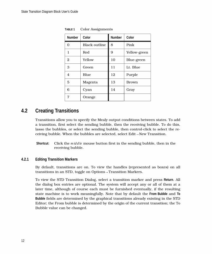
For color workstations, you may specify a color for each bubble. The color is speci-fied via a combo box from which you can choose a number between -14 and 14.Table 1 on page 12 shows the colors that appear on the bubble, any transitions thatcome from the bubble, and documentation information associated with the transi-tions. If the color number is positive, the color is applied as a fill; if negative, as anoutline.
On UNIX platforms you can change default settings for the color assignments. Seethe SystemBuild User’s Guide discussion on the Sysbld resource file.
Diagram Option
The Diagram option field allows you to specify the information to be displayed aboutthis bubble. If you give a name to a bubble, the name will always be displayed onthe bubble, but you may control how Moore mode outputs are displayed by selectingeither Name Only or Name and Outputs .
State Transition Diagram Block User’s Guide
12
4.2 Creating Transitions
Transitions allow you to specify the Mealy output conditions between states. To adda transition, first select the sending bubble, then the receiving bubble. To do this,lasso the bubbles, or select the sending bubble, then control-click to select the re-ceiving bubble. When the bubbles are selected, select Edit→New Transition.
4.2.1 Editing Transition Markers
By default, transitions are on. To view the handles (represented as boxes) on alltransitions in an STD, toggle on Options→Transition Markers.
To view the STD Transition Dialog, select a transition marker and press Return . Allthe dialog box entries are optional. The system will accept any or all of them at alater time, although of course each must be furnished eventually, if the resultingstate machine is to work meaningfully. Note that by default the From Bubble and ToBubble fields are determined by the graphical transitions already existing in the STDEditor; the From bubble is determined by the origin of the current transition; the ToBubble value can be changed.
TABLE 1 Color Assignments
Number Color Number Color
0 Black outline 8 Pink
1 Red 9 Yellow-green
2 Yellow 10 Blue-green
3 Green 11 Lt. Blue
4 Blue 12 Purple
5 Magenta 13 Brown
6 Cyan 14 Gray
7 Orange
Shortcut : Click the middle mouse button first in the sending bubble, then in thereceiving bubble.

State Transition Diagram Block User’s Guide
13
Mealy Outputs and Mealy Description
The STD Transition Dialog box is shown in Figure 8.
You can assign a Name to a transition for documentation purposes. The number ofMealy Outputs specified controls the number of cells in the Mealy Description spreadsheet.To specify that an output is to be asserted (set = 1), type the pin number that theoutput occupies on the STD block. To specify that an output is to be turned off (set= 0), type the negative of the pin number on the transition; see Example 2.
EXAMPLE 2: Turning Pins On and Off
To turn pins 11 and 20 on but pin 2 off, set the Number of Mealy Outputs to 3, thentype 20 -2 11 in the Mealy Output Description field.
The outputs can appear in the field in any order.
The From Bubble and To Bubble fields appear on the transition dialog. The From and To
bubbles are identified by Bubble ID number. If the destination, or To Bubble , field is
FIGURE 8 STD Transition Dialog

State Transition Diagram Block User’s Guide
14
changed in the dialog box, the transition will be redrawn to the new bubble. TheFrom Bubble field is read-only, however.
As with the Bubble dialog box, the Diagram Option field allows you to specify what in-formation is to be displayed about each transition individually. If you give a name toa transition, it will always be displayed next to the handle of the transition line, butyou may also choose to have Activation Condition and/or Mealy Description displayed.Click Diagram Option one or more times to change the setting. In this display, ActivationConditions will always appear in Curly Braces ({} ), and Mealy Outputs appear in SquareBrackets ([] ).
You can enter a Comment for documentation purposes; comments will be includedwith the detail or documentation outputs for the STD.
The Activation Condition Field
Each transition dialog box has an Activation Condition field that must be filled in.Data entered into the condition field determines the events that cause the transitionto be executed. Activation condition field entries are logical functions, just like thosethat form the right-hand sides of logical expressions in SystemBuild’s LogicalEx-pression block (see the online help for the LogicalExpression block, or type help
equations in the Xmath Command Window).
The logical function accepts input signals of the STD as variables and evaluatesthem according to the relations that you express in the Activation Condition field. Eachinput channel can be a different datatype, but input channel usage must be consis-tent across all transitions. This implies that a logical input channel cannot also beused in a numeric expression, and a numeric input channel cannot also be used ina logical expression.
The inputs are labelled U1 through Un, where n is the number of inputs to the STD,and the inputs are numbered from top to bottom on the input side of the STD block.In general, as long as the function may be evaluated for truth or falsity, any conven-tionally valid combination of relational operators linking arithmetic and logical ex-pressions may be used. The properties of these operations are as follows:
Arithmetic Expressions — use conventional combinations of the operations **, *, /, +,and -. Parentheses are used for grouping. They are used to compute a number,which can be compared with another using relational operators.
Relational Operators — used to compare numbers, or (in the case of equals and notequals operators), logical values.

State Transition Diagram Block User’s Guide
15
The relational operators are:
Logical Expressions — built up from inputs or relational comparisons, using any con-ventional combination of NOT, AND, NAND, OR, NOR, EQV, and NEQV. The order ofprecedence for evaluation also follows usual conventions: arithmetic, then rela-tional, then logical; for logical relations the order is NOT, AND/NAND, OR/NOR,EQV/NEQV. Table 2 shows typical logical relations.
Within the active bubble, each of the transitions is evaluated in the prioritized orderuntil a condition is detected as True. Then the state machine transitions to the newbubble pointed to by the particular transition. The Mealy outputs from the transi-tion are set, and the Moore outputs from the new bubble are asserted.
The default transition condition for a transition is True (always transition if thisbubble is reached and this transition has priority). Transition priorities are assignedconsecutively when the transitions are created. Priority 1 is highest. You can changethis priority in the Transition dialog box. All other transitions from this bubble areautomatically updated to ensure that the priorities form a list of consecutive inte-gers from 1 to the number of transitions.
lt or < Less than
gt or > Greater than
ge or >= Greater or equal
le or <= Less than or equal
eq or = Equals
ne or <> Not Equal
TABLE 2
Relation Action
U1 le U2 Arithmetic compare
Not(u3 or U4) Logical compare
True Unconditional
U5 gt 0 Compare a literal
U6**2 + 1 >= u7 Evaluate, then compare
u8 <> 0 Logic test

State Transition Diagram Block User’s Guide
16
4.2.2 Editing Transition Lines
When they are first entered, transition lines appear as straight lines, and where twolines connect two bubbles (in one direction or both), they appear as one. To pull thelines into arcs, drag the transition marker or handle rectangles on each transition.Figure 9 shows this behavior on the transitions between bubbles 1 and 3. The tran-sitions appear as a single two-headed arrow.
To separate the lines into two arcs, click the mouse button on the handle of the lineto be moved, hold the button down, and move the cursor in a direction away fromthe line. The first transition line that was entered will be the first one moved. Repeatthe process to move multiple lines. See Figure 10 on page 17 for the result of thisprocess.
Transition markers appear at the center of the transition lines, but they can bemoved along the lines. Click on a marker and drag it in any direction. The transitionmarkers determine the location of the transition name.
FIGURE 9 STD with Double Transition between Bubbles 1 and 3

State Transition Diagram Block User’s Guide
17
To create a transition that loops back to itself, (e.g., to create an activate output or adelay) click the middle mouse button within the bubble, then click again after a mo-ment (do not double-click).
To edit a transition, place the cursor over the transition marker box and press Re-turn ; the STD transition dialog appears.
5 SuperBubbles
A SuperBubble is a single bubble that represents a group of bubbles; SuperBubblesare used to visually simplify large bubble diagrams by introducing hierarchies; Su-perBubbles may be nested up to 200 levels deep.
SuperBubbles resemble SuperBlocks in that they are graphics abstractions that en-able you to impose a visible hierarchy on the state diagram. Unlike SuperBlocks,however, the hierarchies of SuperBubbles impose no timing properties or other at-tributes on the bubbles under them; the hierarchy is completely disregarded when
FIGURE 10 STD with Double Transition Resolved

State Transition Diagram Block User’s Guide
18
the system is analyzed for simulation. They are not carried as entries in the System-Build catalog, and they cannot be called or reused by other STDs.
Follow these steps to create a SuperBubble:
1. Select the group of bubbles to be combined into a SuperBubble. To select, lassoa group of bubbles, or, select a bubble then Control-click the left mouse buttonto select each additional bubble in the group.
2. Select Edit→Make SuperBubble. A SuperBubble replaces the selected bubblesin the current diagram; the selected bubbles and all related transitions aremoved to a subhierarchy.
On the screen, a SuperBubble looks like an ordinary bubble with a dotted bor-der. Transitions to/from the bubbles in the SuperBubble are shown in theusual manner, but with labels that indicate which bubble and transition num-ber is at the terminus within the SuperBubble.
3. To traverse down the hierarchy to the child bubbles, double-click in the Super-Bubble. to return to the parent, type P, or, select the View Parent icon from theSTD editor icon bar.
4. To return the child SuperBubbles to the original level, select the Parent Super-Bubble, then select Edit→Expand SuperBubble. The SuperBubble is replacedby the individual bubbles, and the hierarchy no longer exists.
SuperBubbles cease to exist when they are expanded or when the bubbles underthem are all deleted.
See Figure 2 on page 4 for a typical bubble diagram with no SuperBubbles.Figure 11 on page 19 shows the same bubble diagram with two of the bubbles orga-nized into a SuperBubble. Observe that the transitions into and out of the Super-Bubble are shown clearly, but the internal transitions are not visible.
Figure 12 on page 19 shows the SuperBubble opened for editing. Bubbles 3 and 4have returned to the screen. Their transitions to the outside world are visible asstubs, and the transitions of bubble 1 are shown with square blocks to indicate thatthey are inputs to this diagram. The transition out of bubble 3 is shown as an arrowto “nowhere,” with a number next to the transition handle indicating the serialnumber of the receiving bubble.
Each bubble in an STD has a system-assigned serial number; these are assigned tobubbles and SuperBubbles indiscriminately. No provision is made for allowing auser to change these numbers. However, when a bubble is deleted, its serial numberis returned to the pool, and a number may be reused under these circumstances.

State Transition Diagram Block User’s Guide
19
FIGURE 11 Bubble Diagram with a SuperBubble
FIGURE 12 Expanded SuperBubble

State Transition Diagram Block User’s Guide
20
You can display the STD icon with the bubble diagram expanded and visible, butshrunk to fit inside the icon, as shown in Figure 13. To do this select the block thenselect User or Alternate from the icon type pulldown on the SuperBlock editor iconbar.
FIGURE 13 STD Display with User Icon Type Selected

21
Index
Aarithmetic expressions, STDs 14
asserting signals, STDs 11, 13
BBubble Dialog Box 10
bubbles
creating diagrams 8
definition 1
displaying diagrams 20
moving 10
DDiagram Option 11
Ffinite state machines, defined 1
Iinitial bubble 9
Llogical
expressions, STDs 15
functions, STDs 14
MMealy Mode
example 5
outputs 2, 3, 5
Moore and Mealy Modes, illustrated 2
Moore Mode
example 4
outputs 2
Rrelational operators, STDs 15
SState Transition Diagrams (STD) 1
state, bubbles in STDs 1
STD Editor 8
STD outputs, Moore and Mealy modes 3
STD, State Transition Diagrams 1
SuperBubbles 17
and SuperBlocks, compared 17
traversing the hierarchy 18
Sysbld, SystemBuild resource file 11

Index State Transition Diagram Block User’s Guide
22
TTechnical Support (see support) vii
transition
definition 1
lines 16
markers 16
priorities 15
viewing 12

Technical Support and Professional Services
Visit the following sections of the National Instruments Web site at ni.com for technical support and professional services:
• Support—Online technical support resources include the following:
– Self-Help Resources—For immediate answers and solutions, visit our extensive library of technical support resources available in English, Japanese, and Spanish at ni.com/support. These resources are available for most products at no cost to registered users and include software drivers and updates, a KnowledgeBase, product manuals, step-by-step troubleshooting wizards, conformity documentation, example code, tutorials and application notes, instrument drivers, discussion forums, a measurement glossary, and so on.
– Assisted Support Options—Contact NI engineers and other measurement and automation professionals by visiting ni.com/support. Our online system helps you define your question and connects you to the experts by phone, discussion forum, or email.
• Training—Visit ni.com/training for self-paced tutorials, videos, and interactive CDs. You also can register for instructor-led, hands-on courses at locations around the world.
• System Integration—If you have time constraints, limited in-house technical resources, or other project challenges, NI Alliance Program members can help. To learn more, call your local NI office or visit ni.com/alliance.
If you searched ni.com and could not find the answers you need, contact your local office or NI corporate headquarters. Phone numbers for our worldwide offices are listed at the front of this manual. You also can visit the Worldwide Offices section of ni.com/niglobal to access the branch office Web sites, which provide up-to-date contact information, support phone numbers, email addresses, and current events.