MATRIX SPINE SYSTEM
39
MATRIX SPINE SYSTEM – PERFORATED Surgical Technique
Transcript of MATRIX SPINE SYSTEM

MATRIX SPINE SYSTEM– PERFORATED
Surgical Technique

Image intensifier control
This description alone does not provide sufficient background for direct use of DePuy Synthes products. Instruction by a surgeon experienced in handling these products is highly recommended.
Processing, Reprocessing, Care and Maintenance
For general guidelines, function control and dismantling of multi-part instru-ments, as well as processing guidelines for implants, please contact your local sales representative or refer to:
http://emea.depuysynthes.com/hcp/reprocessing-care-maintenance
For general information about reprocessing, care and maintenance of Synthes reusable devices, instrument trays and cases, as well as processing of Synthes non-sterile implants, please consult the Important Information leaflet (SE_023827) or refer to: http://emea.depuysynthes.com/hcp/reprocessing-care-maintenance
Table of Contents
3MATRIX Spine System – Perforated • Surgical Technique
Image Intensifier Control
▲ Warnings/Precautions
Introduction MATRIX Spine System – Perforated 4
Implants 5
Augmentation Options – Overview 8
Surgical Technique Preoperative Planning 10
Kirschner Wire Handling 11
Open Approach 12
Cement Handling 16
Place Screwheads 22
Attach construct 24
MIS Approach 25
Implant Removal 32
Implants 33
Instruments 34
Warnings 36
Bibliography 37
Indications and Contraindications 38
4 Surgical Technique • MATRIX Spine System – Perforated
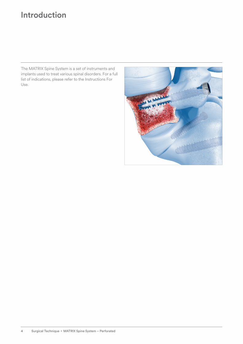
The MATRIX Spine System is a set of instruments and implants used to treat various spinal disorders. For a full list of indications, please refer to the Instructions For Use.
Introduction
5MATRIX Spine System – Perforated • Surgical Technique
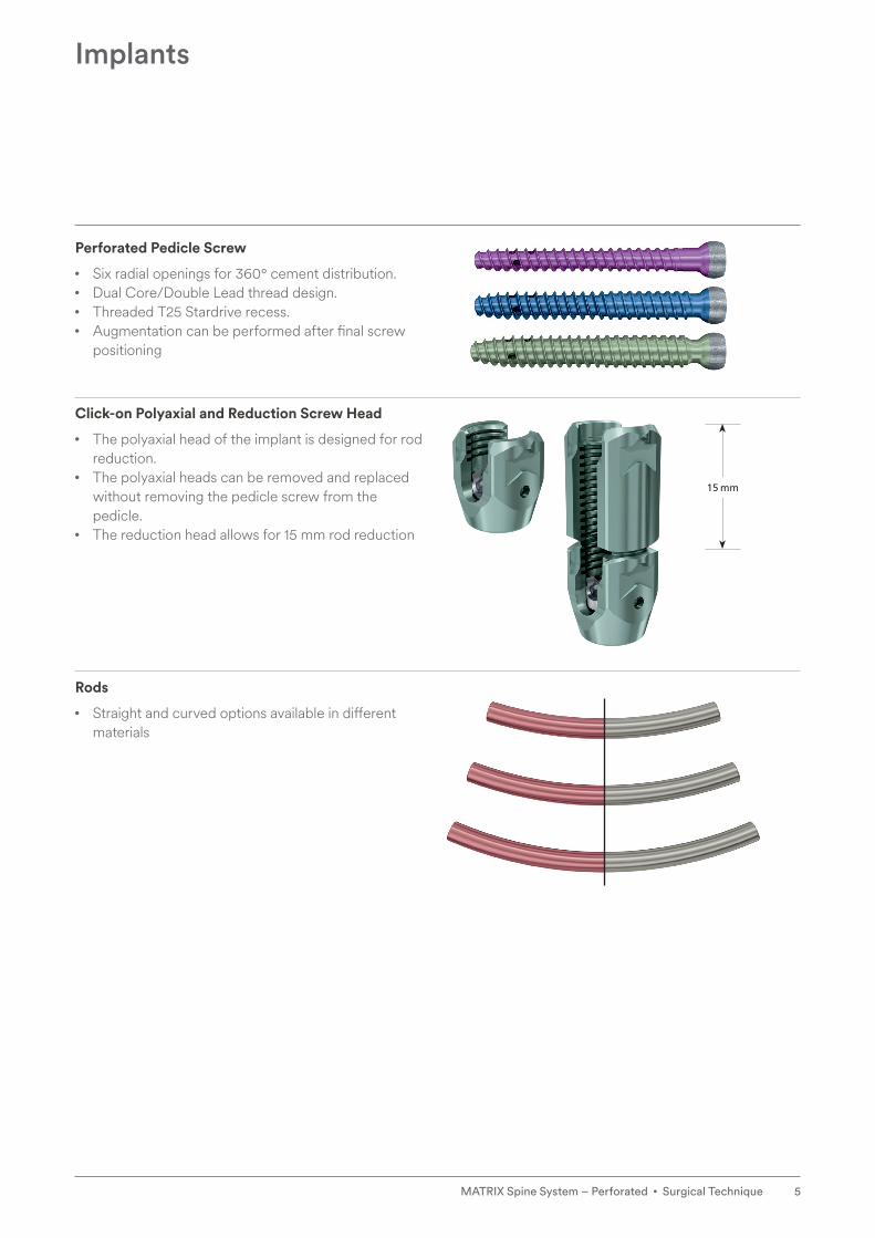
Perforated Pedicle Screw
• Six radial openings for 360° cement distribution.• Dual Core/Double Lead thread design.• Threaded T25 Stardrive recess.• Augmentation can be performed after final screw
positioning
Click-on Polyaxial and Reduction Screw Head
• The polyaxial head of the implant is designed for rod reduction.
• The polyaxial heads can be removed and replaced without removing the pedicle screw from the pedicle.
• The reduction head allows for 15 mm rod reduction
Rods
• Straight and curved options available in different materials
Implants
15 mm
6 Surgical Technique • MATRIX Spine System – Perforated
Dual Core/Double Lead Screw Design
• Dual core and double lead thread design.• Rounded blunt tip and self-tapping thread.• Threaded T25 Stardrive recess
Modularity
• Customized inventory possible.• Available as click-on and pre-assembled screws.• Click on before or after screw insertion.• The polyaxial heads can be removed and replaced
without removing the pedicle screw from the pedicle
Implants
7MATRIX Spine System – Perforated • Surgical Technique
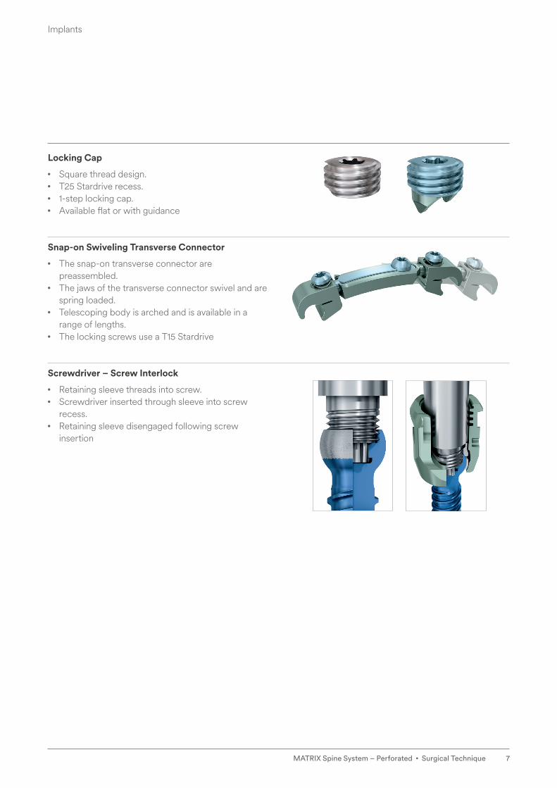
Locking Cap
• Square thread design.• T25 Stardrive recess.• 1-step locking cap.• Available flat or with guidance
Snap-on Swiveling Transverse Connector
• The snap-on transverse connector are preassembled.
• The jaws of the transverse connector swivel and are spring loaded.
• Telescoping body is arched and is available in a range of lengths.
• The locking screws use a T15 Stardrive
Screwdriver – Screw Interlock
• Retaining sleeve threads into screw.• Screwdriver inserted through sleeve into screw
recess.• Retaining sleeve disengaged following screw
insertion
Implants

8 Surgical Technique • MATRIX Spine System – Perforated
Augmentation Options – Overview
Options a. Simple Adapter b. Needle Adapter Kit c. Guide Sleeve and Locking Needle Adapter
Open approach c c (c)
Open approach with Kirschner wire
c c (c)
Minimally invasive approach with MATRIX MIS
– – c
Characteristics • Tactile feedback of recess connection
• Direct application of cement
• Applied volume readable on syringe
• Maneuverable through soft tissue
• Can be connected prior to screwing on the syringe, independent of cement preparation
• Same interface to screw recess as simple adapter
• Guide sleeve connects to distractor tip
• Distractor tip forms connection between instrument and bone screw
• Assembly of guide sleeve for MATRIX augmentation and locking needle adapter is independent of cement preparation

AO Spine Principles
1. Aebi M, Thalgott JS, Webb JK (1998) AO/ASIF Principles in Spine Surgery. Springer-Verlag, Germany.
2. Aebi M, Arlet V, Webb JK (2007): AOSPINE Manual (2 vols), Stuttgart, New York: Thieme.
The four principles to be considered as the foundation for proper spine patient management underpin the design and delivery of the Curriculum: Stability, Alignment, Biology, Function.1,2
AO Principles1,2
1. 2. 3. 4.
Stability
Stabilization to achieve a specific therapeutic outcome.
Alignment
Balancing the spine in three dimensions.
Biology
Etiology, pathogenesis, neural protection, and tissue healing.
Function
Preservations and res-toration of function to prevent disability.
MATRIX Spine System – Perforated • Surgical Technique 9
10 Surgical Technique • MATRIX Spine System – Perforated
Preoperative planning includes evaluation and assess-ment of the patient with regard to the specifications of the bone cement used for augmenting MATRIX perfo-rated screws (see Vertecem V+ System surgical technique).
Proper imaging equipment must be used to determine correct implant dimensions in relation to the anatomy.
The decision whether or not to augment MATRIX per-forated screws can be taken intraoperatively, based on tactile feedback upon pedicle preparation and screw insertion. If screws are augmented, bilateral screw aug-mentation is recommended.
▲ Warning
• Handling knowledge of VERTECEM V+ is required prior to augmentation of perforated screws.
• Attention should be given to the “Notes and Warnings” section of this Surgical Technique Guide.
• Ensure you are familiar with the IFU, including the side effects, precautions and warnings associated with VERTECEM V+.
• Image intensifier control is mandatory while inject-ing cement.
Preoperative Planning

11MATRIX Spine System – Perforated • Surgical Technique
▲ Warning
• Ensure the Kirschner wires remain securely in posi-tion throughout the entire duration of the proce-dure. The tip of the Kirschner wire should be monitored by image intensifier to ensure it does not penetrate the anterior wall of the vertebral body and damages the vessels situated in front.
• Ensure the Kirschner wires do not slip out before the screws are inserted. The Kirschner wires are long enough to be held in place by hand during pedicle preparation and soft tissue dilation.
• Insert the screw until the tip of the screw is beyond the posterior wall of the vertebral body and remove the Kirschner wire in order to avoid uncontrolled further advancing.
Bi-planar fluoroscopy with two C-arms allows a safer, easier and quicker radiographic assessment during the surgical procedure.
▲ Precaution
• To avoid glove damage, ensure that the exit point for the Kirschner Wire is not blocked.
Kirschner Wire Handling

12 Surgical Technique • MATRIX Spine System – Perforated
This surgical technique contains supplementary instruc-tions on handling Perforated MATRIX pedicle screws. For handling standard MATRIX pedicle screws please refer to the MATRIX Spine System – Degenerative sur-gical technique and for cannulated screws the MATRIX Spine System – MIS surgical technique.
Screws may be placed both unassembled and preas-sembled. If screws need to be placed preassembled, please follow assembly technique as described on page 29 prior to screw placement
1. Prepare pedicles and insert screws Options a and b (compare “Options” page 6)
Open and prepare pedicles and insert screws as defined in chapter screw insertion of the MATRIX Spine System – Degenerative surgical technique. Alternatively, screw placement with Kirschner wire can be performed as described in the MATRIX Spine System – MIS surgi-cal technique.
Instruments
01.632.220 Set for Basic Instruments, for MATRIX 5.5
01.616.106 Set, perforated for No. 01.637.003, for Matrix MIS, sterile
Sufficient preparation of the screw channel is necessary to remove bone residuals.
Select appropriate screw lengths. Choose screws with the maximum possible diameter and length to achieve stability.
▲ Precaution
• The MATRIX Perforated screw must enter in approximately 80% of the vertebral body (1).
• If the screws are too short, the bone cement might be injected too close to the pedicle. It is required that the screw perforations are located in the verte-bral body, close to the anterior cortical wall. For this reason 35 mm screws should be placed in the sacrum only.
• If the screws are too long, or placed bi-cortically, the anterior cortical wall may be penetrated and cement leakage might occur.
Open Approach
Correct Incorrect
1

13MATRIX Spine System – Perforated • Surgical Technique
Option c (compare “Options” page 6)
Instruments
03.632.085 Retaining Sleeve, detachable, for Matrix 5.5
03.632.073 Screwdriver Shaft, T25, cannulated, long
03.632.083 Distractor Tip, for Bone Screws, for Matrix 5.5
03.620.061 T-Handle with Ratchet Wrench and with Torque Limiter, 10 Nm
03.637.001 Guide Sleeve for Matrix perforated Pedicle Screw
Slide detachable retaining sleeve over long cannulated T25 screwdriver shaft. Slide the distractor tip over the screwdriver shaft tip and press firmly into the detach-able retaining sleeve (1).
Insert the tip of the screwdriver shaft into the bone screw interface. Make sure that the tip of the screw-driver shaft is fully seated in the recess of the bone screw interface. Turn the green knob clockwise.
Insert the pedicle screw.
To release the detachable retaining sleeve from the dis-tractor tip, pull the green knob towards the handle. Remove the screwdriver and retaining sleeve. The dis-tractor tip will stay on the screw (2).
▲ Precaution
• Do not grasp the green knob during insertion as it will cause the retaining sleeve to disengage from the screw
Open Approach
2
1

14 Surgical Technique • MATRIX Spine System – Perforated
Sufficient preparation of the screw channel is necessary to remove bone residuals.
Select appropriate screw lengths. Choose screws with the maximum possible diameter and length to achieve stability.
▲ Precaution
• The MATRIX Perforated screw must enter in approximately 80% of the vertebral body (3).
• If the screws are too short, the bone cement might be injected too close to the pedicle. It is required that the screw perforations are located in the verte-bral body, close to the anterior cortical wall. For this reason 35 mm screws should be placed in the sacrum only.
• If the screws are too long, or placed bi-cortically, the anterior cortical wall may be penetrated and cement leakage might occur.
Insert the guide sleeve over the distractor tip and push down firmly until tactile feedback (4).
▲ Precaution
• Thoroughly rotate the lateral arms of the guide sleeve clockwise to ensure that the distractor tip is fully engaged with the screw. For later augmenta-tion only the Locking Needle Adapter Kit with Luer-Lock should be used with the Guide Sleeve for MATRIX Perforated Screw.
Open Approach
3
4
Correct Incorrect

15MATRIX Spine System – Perforated • Surgical Technique
2. Assess proper screw placement
Instrument
02.648.001 Cleaning Stylet for perforated Pedicle Screws
Assess the cortical shell for perforations in the vertebral body.
▲ Warning
• In case of any perforation, special caution is required when bone cement is applied. Cement leakage and its related risks may compromise the physical condition of the patient.
▲ Precaution
• The MATRIX Perforated screw must enter in approximately 80% of the vertebral body (1).
• If the screws are too short, the bone cement might be injected too close to the pedicle. It is required that the screw perforations are located in the verte-bral body, close to the anterior cortical wall. For this reason 35 mm screws should be placed in the sacrum only.
• If the screws are too long, or placed bi-cortically, the anterior cortical wall may be penetrated and cement leakage might occur.
Use the cleaning stylet to clear the cannula for proper cement injection (2, 3). Visualize the stylet position under image intensifier control (4).
Open Approach
2
1
2 3
4
Correct
Options a, b
Incorrect
Option c

16 Surgical Technique • MATRIX Spine System – Perforated
1. Prepare cement
Implant
07.702.016S Vertecem V+ Cement Kit, sterile
Instrument
03.702.215S Vertecem V+ Syringe Kit
For handling VERTECEM V+ Cement, please re fer to the VERTECEM V+ Surgical Technique
Cement Handling

17MATRIX Spine System – Perforated • Surgical Technique
2. Injection Preparation
Place the C-arm in a lateral position to monitor the extrusion of the cement into the vertebral body.
Additional image intensifier control in the AP projection is recommended.
Cement Handling
Option a:
Simple Adapter
Option b:
Needle Adapter Kit
Option c:
Guide Sleeve and Locking Needle Adapter

18 Surgical Technique • MATRIX Spine System – Perforated
2a. Simple Adapter
07.702.216.02S Simple Adapter for perforated Pedicle Screws, with Luer-Lock, 2 pieces, sterile
Attach simple adapter onto the syringe.
Connect the syringe with the adapter to the screw and press down firmly. Make sure the adapter is fully intro-duced into the screw recess.
▲ Warning
• Care should be taken when exchanging the syringes as cement might be left in the Stardrive head of the screw. If simple adapter is used, only VERTECEM V+ 2cc syringes should be used to inject cement in order to avoid disconnecting and reconnecting of the syringe.
Cement Handling

19MATRIX Spine System – Perforated • Surgical Technique
2b. Needle Adapter Kit
03.702.224.02S Needle Adapter Kit for perforated Pedicle Screws, with Luer-Lock, sterile
Connect the needle adapter to the screw and press down firmly.
Turning clockwise, attach the pre-filled syringe onto the LuerLock.
2c. Guide Sleeve and Locking Needle Adapter
07.702.217.02S Locking Needle Adapter Kit for perforated Pedicle Screws, with Luer-Lock, sterile
Introduce the locking needle adapter into the guide sleeve, locking it in with a slight push 1 and then with a clockwise turn 2 (1).
Turning clockwise, attach the pre-filled syringe onto the Luer-Lock (2).
• Ensure that the locking needle adapter is properly locked in.
Cement Handling
1
2
(1)
(2)
20 Surgical Technique • MATRIX Spine System – Perforated
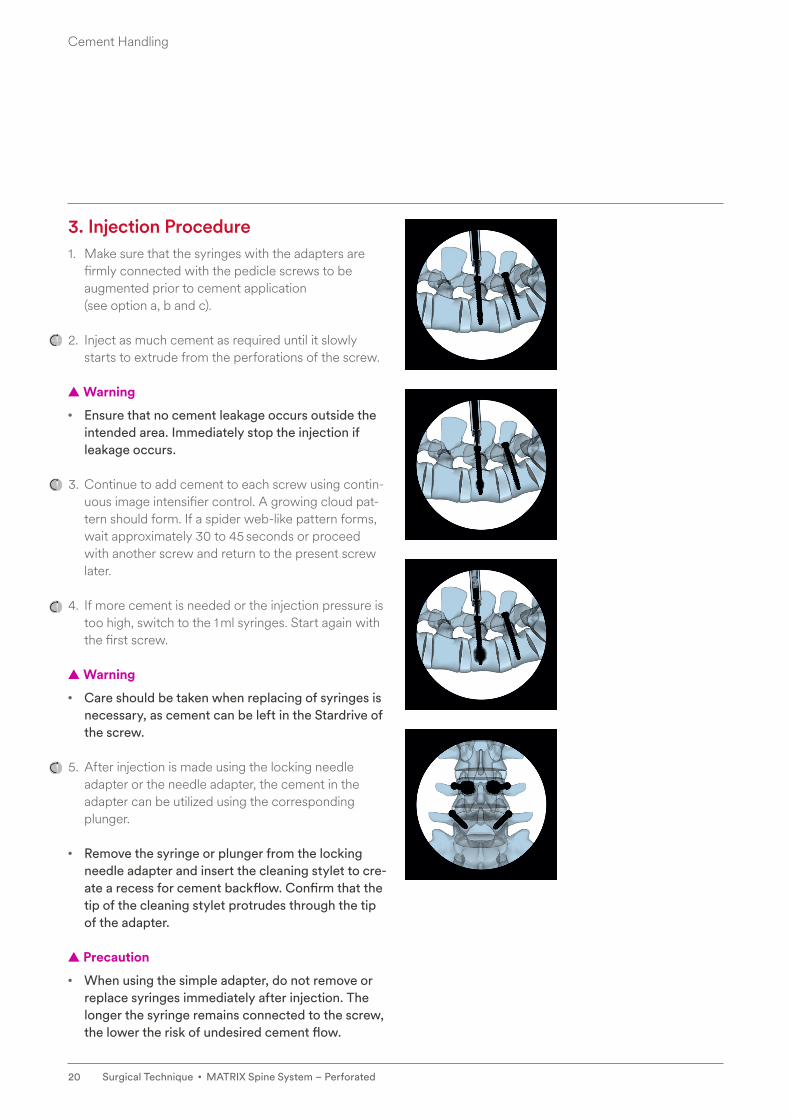
3. Injection Procedure1. Make sure that the syringes with the adapters are
firmly connected with the pedicle screws to be augmented prior to cement application (see option a, b and c).
2. Inject as much cement as required until it slowly starts to extrude from the perforations of the screw.
▲ Warning
• Ensure that no cement leakage occurs outside the intended area. Immediately stop the injection if leakage occurs.
3. Continue to add cement to each screw using contin-uous image intensifier control. A growing cloud pat-tern should form. If a spider web-like pattern forms, wait approximately 30 to 45 seconds or proceed with another screw and return to the present screw later.
4. If more cement is needed or the injection pressure is too high, switch to the 1 ml syringes. Start again with the first screw.
▲ Warning
• Care should be taken when replacing of syringes is necessary, as cement can be left in the Stardrive of the screw.
5. After injection is made using the locking needle adapter or the needle adapter, the cement in the adapter can be utilized using the corresponding plunger.
• Remove the syringe or plunger from the locking needle adapter and insert the cleaning stylet to cre-ate a recess for cement backflow. Confirm that the tip of the cleaning stylet protrudes through the tip of the adapter.
▲ Precaution
• When using the simple adapter, do not remove or replace syringes immediately after injection. The longer the syringe remains connected to the screw, the lower the risk of undesired cement flow.
Cement Handling

21MATRIX Spine System – Perforated • Surgical Technique
▲ Warning
• The cement flow follows the path of least resis-tance. Therefore it is mandatory, during the whole injection procedure, to maintain real-time image intensifier control in the lateral projection. In case of unexpected cloud forming patterns or if the cement is not clearly visible, the injection must be stopped immediately.
• Any cement remaining in the screw drive must be removed with the cleaning stylet while it is still soft (or has not hardened yet). This will ensure that future revision surgeries remain possible.
• Wait until the cement has cured before removing adapters and continuing with the instrumentation (about 15 minutes after last injection).
Cement Handling
22 Surgical Technique • MATRIX Spine System – Perforated
Instruments
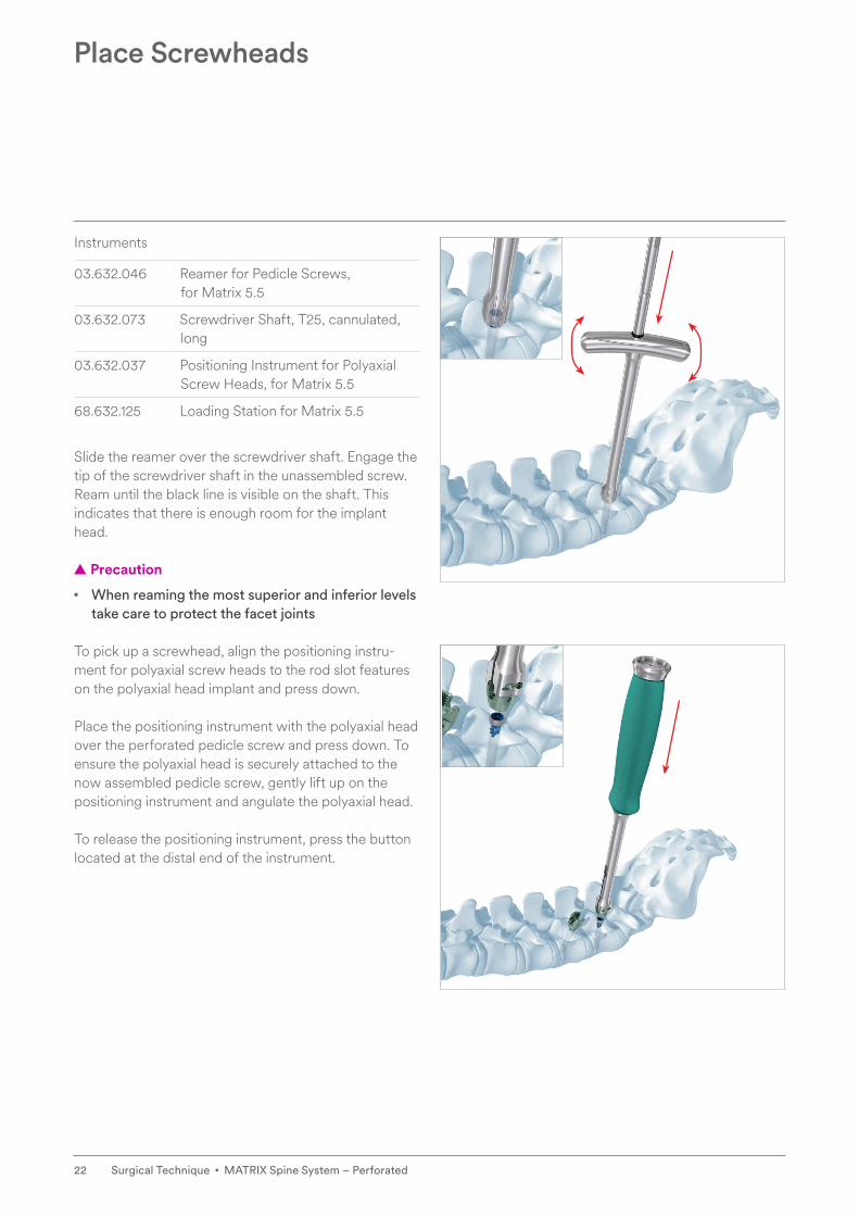
03.632.046 Reamer for Pedicle Screws, for Matrix 5.5
03.632.073 Screwdriver Shaft, T25, cannulated, long
03.632.037 Positioning Instrument for Polyaxial Screw Heads, for Matrix 5.5
68.632.125 Loading Station for Matrix 5.5
Slide the reamer over the screwdriver shaft. Engage the tip of the screwdriver shaft in the unassembled screw. Ream until the black line is visible on the shaft. This indicates that there is enough room for the implant head.
▲ Precaution
• When reaming the most superior and inferior levels take care to protect the facet joints
To pick up a screwhead, align the positioning instru-ment for polyaxial screw heads to the rod slot features on the polyaxial head implant and press down.
Place the positioning instrument with the polyaxial head over the perforated pedicle screw and press down. To ensure the polyaxial head is securely attached to the now assembled pedicle screw, gently lift up on the positioning instrument and angulate the polyaxial head.
To release the positioning instrument, press the button located at the distal end of the instrument.
Place Screwheads

23MATRIX Spine System – Perforated • Surgical Technique
▲ Precautions
• Before placing a polyaxial head onto the perforated screw, ensure that the cement has completely cured.
▲ Warning
• Always use image intensifier control when placing polyaxial heads to ensure that the screw does not advance. If the screw advances, wait for the cement to cure.
• If the polyaxial head does not successfully attach to the head of the unassembled pedicle screw, addi-tional reaming or screw height adjustment may be required to ensure sufficient space exists to allow free mobility of the head.
• Polyaxial screw heads can be removed a maximum of three times without removing the pedicle screw; a new head must be used for each assembly.
Place Screwheads

24 Surgical Technique • MATRIX Spine System – Perforated
Continue with the steps “Insert Rod”, “Insert Locking Cap” and “Perform Final Tightening”, from the MATRIX Spine System – Degenerative surgical technique.
▲ Warning
• Distraction/compression might lead to loosening of the augmented screws resulting in construct failure.
• Prior to performing correction maneuvers ensure that the cement is fully hardened.
Attach construct
25MATRIX Spine System – Perforated • Surgical Technique
This surgical technique option contains instructions on handling Perforated MATRIX pedicle screws using a minimally invasive approach with the MATRIX MIS Instrumentation System.
For handling cannulated screws please refer to the MATRIX Spine System – MIS surgical technique.
Instruments
01.616.106 Set, perforated for No. 01.637.003, for Matrix MIS, sterile
03.632.085 Retaining Sleeve, detachable, for Matrix 5.5
03.637.001 Guide Sleeve for Matrix perforated Pedicle Screw
07.702.217.02S Locking Needle Adapter Kit for perforated Pedicle Screws, with Luer-Lock, sterile
68.632.125 Loading Station for Matrix 5.5
03.632.037 Positioning Instrument for Polyaxial Screw Heads, for Matrix 5.5
02.648.001 Cleaning Stylet for perforated Pedicle Screws
Sufficient preparation of the screw channel is necessary to remove bone residuals.
Perform screw placement with Kirschner wire as described in the MATRIX Spine System – MIS Surgical Technique.
MIS Approach
26 Surgical Technique • MATRIX Spine System – Perforated
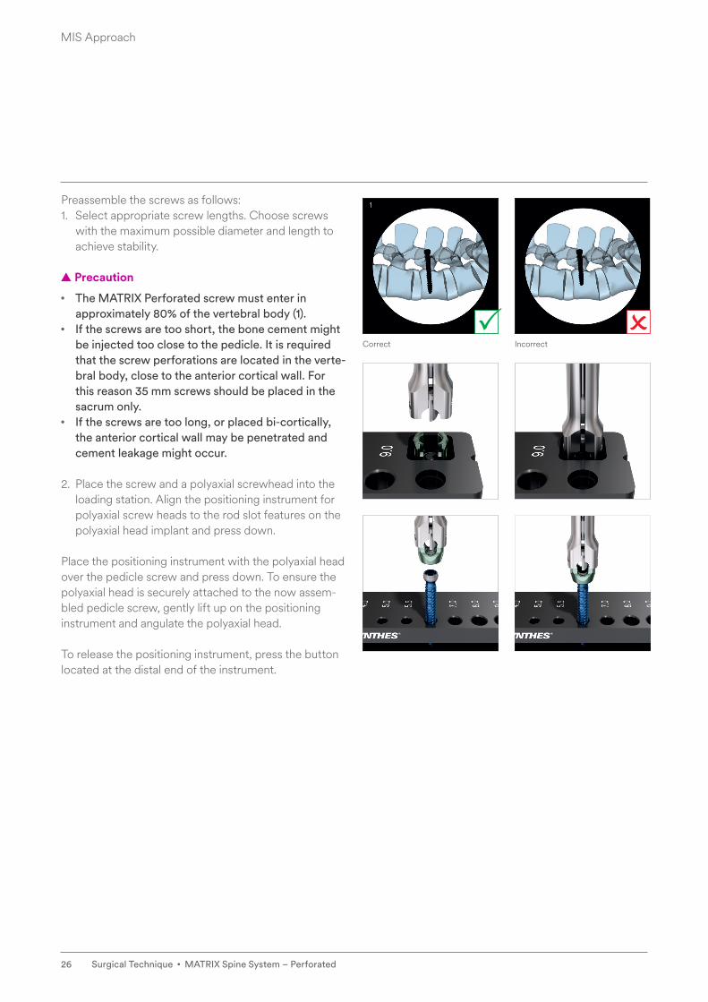
Preassemble the screws as follows:1. Select appropriate screw lengths. Choose screws
with the maximum possible diameter and length to achieve stability.
▲ Precaution
• The MATRIX Perforated screw must enter in approximately 80% of the vertebral body (1).
• If the screws are too short, the bone cement might be injected too close to the pedicle. It is required that the screw perforations are located in the verte-bral body, close to the anterior cortical wall. For this reason 35 mm screws should be placed in the sacrum only.
• If the screws are too long, or placed bi-cortically, the anterior cortical wall may be penetrated and cement leakage might occur.
2. Place the screw and a polyaxial screwhead into the loading station. Align the positioning instrument for polyaxial screw heads to the rod slot features on the polyaxial head implant and press down.
Place the positioning instrument with the polyaxial head over the pedicle screw and press down. To ensure the polyaxial head is securely attached to the now assem-bled pedicle screw, gently lift up on the positioning instrument and angulate the polyaxial head.
To release the positioning instrument, press the button located at the distal end of the instrument.
MIS Approach
1
Correct Incorrect

27MATRIX Spine System – Perforated • Surgical Technique
3. Press the slim retraction blades for mini-open tech-nique onto the pedicle screw until they snap together (1).
To connect the slim retraction blades for percutaneous technique to the screw, snap the first blade onto one side of the pedicle screw (2).
Then snap a second blade onto the opposite side of the pedicle screw.
▲ Precaution
• To avoid glove damage, do not hold the retraction blades near the bottom of the deflecting tab.
Check with a brief “push and pull” of the retraction blade/screw construct to ensure secure attachment of the blades.
Slide detachable retaining sleeve over long cannulated T25 screwdriver shaft. Slide the distractor tip over the screwdriver shaft tip and press firmly into the detach-able retaining sleeve.
Insert the tip of the screwdriver shaft into the bone screw interface. Make sure that the tip of the screw-driver shaft is fully seated in the recess of the bone screw interface. Turn the green knob clockwise.
MIS Approach
1
2

28 Surgical Technique • MATRIX Spine System – Perforated
Insert the pedicle screws as described in chapter “Screw Insertion” from the MATRIX MIS surgical tech-nique (1).
▲ Precaution
• The MATRIX Perforated screw must enter in approximately 80% of the vertebral body (1).
• If the screws are too short, the bone cement might be injected too close to the pedicle. It is required that the screw perforations are located in the verte-bral body, close to the anterior cortical wall. For this reason 35 mm screws should be placed in the sacrum only.
• If the screws are too long, or placed bi-cortically, the anterior cortical wall may be penetrated and cement leakage might occur
Assess proper screw placement as described in chap-ter Open Approach in step 2 on page 15 (2).
MIS Approach
1
2
Correct Incorrect

29MATRIX Spine System – Perforated • Surgical Technique
Release the detachable retaining sleeve from the dis-tractor tip by pulling the green knob towards the han-dle. Remove the cannulated screwdriver and retaining sleeve (3).
MIS Approach
3

30 Surgical Technique • MATRIX Spine System – Perforated
Insert the guide sleeve over the distractor tip and push down firmly until tactile feedback (1).
▲ Precaution
• Thoroughly rotate the lateral arms of the guide sleeve clockwise to ensure that the distractor tip is fully engaged with the screw.
Use the cleaning stylet through the guide sleeve to clear the cannula for proper cement injection.
Visualize the stylet position under image intensifier control.
• Only the locking needle adapter kit with Luer-Lock should be used with the guide sleeve for MATRIX perforated screws.
Introduce the locking needle adapter into the guide sleeve, locking it in with a slight push and a clockwise turn (2). Prepare the cement and fill the injection syringes as described in the chapter Cement Handling.
Turning clockwise, attach the pre-filled syringe onto the Luer-Lock.
• Ensure that the locking needle adapter is properly locked in.
Inject the cement under image intensifier control as described in step 4 in chapter Cement Handling (3).
Remove the syringe or plunger from the adapter and insert the cleaning stylet to create a recess for the cement backflow (4).
▲ Precaution
• Wait until the cement has cured before removing adapters and continuing with the instrumentation (about 15 minutes after last injection).
MIS Approach
1 2
3 4
31MATRIX Spine System – Perforated • Surgical Technique
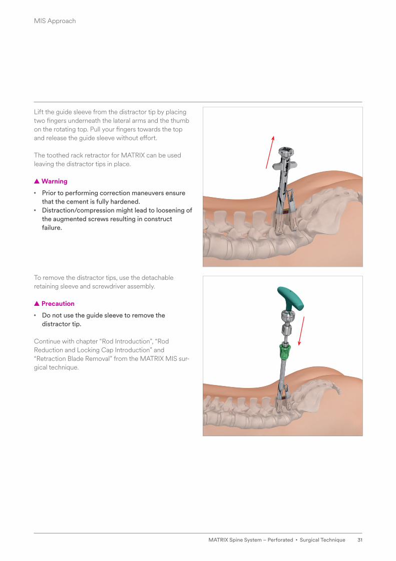
Lift the guide sleeve from the distractor tip by placing two fingers underneath the lateral arms and the thumb on the rotating top. Pull your fingers towards the top and release the guide sleeve without effort.
The toothed rack retractor for MATRIX can be used leaving the distractor tips in place.
▲ Warning
• Prior to performing correction maneuvers ensure that the cement is fully hardened.
• Distraction/compression might lead to loosening of the augmented screws resulting in construct failure.
To remove the distractor tips, use the detachable retaining sleeve and screwdriver assembly.
▲ Precaution
• Do not use the guide sleeve to remove the distractor tip.
Continue with chapter “Rod Introduction”, “Rod Reduction and Locking Cap Introduction” and “Retraction Blade Removal” from the MATRIX MIS sur-gical technique.
MIS Approach

32 Surgical Technique • MATRIX Spine System – Perforated
Please refer to the MATRIX - Degenerative Surgical Technique Guide for guidance on the removal of MATRIX Perforated Implants.
Implant Removal
33MATRIX Spine System – Perforated • Surgical Technique
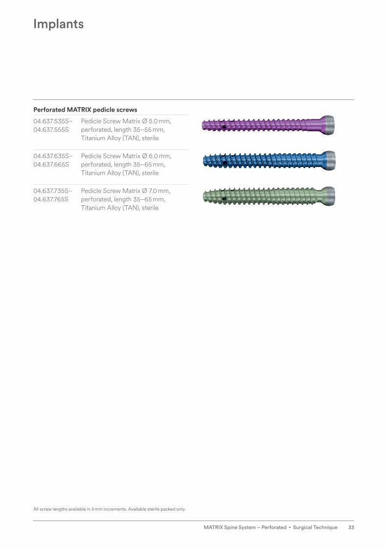
Perforated MATRIX pedicle screws
04.637.535S– Pedicle Screw Matrix Ø 5.0 mm,04.637.555S perforated, length 35–55 mm,
Titanium Alloy (TAN), sterile
04.637.635S– Pedicle Screw Matrix Ø 6.0 mm,04.637.665S perforated, length 35–65 mm,
Titanium Alloy (TAN), sterile
04.637.735S– Pedicle Screw Matrix Ø 7.0 mm,04.637.765S perforated, length 35–65 mm,
Titanium Alloy (TAN), sterile
Implants
All screw lengths available in 5 mm increments. Available sterile packed only.

34 Surgical Technique • MATRIX Spine System – Perforated
07.702.016S Vertecem V+ Cement Kit, sterile
03.702.215S Vertecem V+ Syringe Kit
07.702.216.02S Simple Adapter for perforated Pedicle Screws, with Luer-Lock, 2 pieces, sterile
03.702.224.02S Needle Adapter Kit for perforated Pedicle Screws, with Luer-Lock, 2 pieces, sterile
07.702.217.02S Locking Needle Adapter Kit for perforated Pedicle Screws, with Luer-Lock, sterile
Instruments

35MATRIX Spine System – Perforated • Surgical Technique
68.632.125 Loading Station for Matrix 5.5
02.648.001 Cleaning Stylet for perforated Pedicle Screws
03.632.037 Positioning Instrument Polyaxial Screw Heads, for Matrix 5.5
03.632.083 Distractor Tip, for Bone Screws, for Matrix 5.5
03.632.085 Retaining Sleeve, detachable, for Matrix 5.5
03.637.001 Guide Sleeve for Matrix perforated Pedicle Screw
03.632.073 Screwdriver Shaft, T25, cannulated, long
Instruments

36 Surgical Technique • MATRIX Spine System – Perforated
Handling knowledge of VERTECEM V+ is required prior to the augmentation of any screws, with particular emphasis being paid to “fill patterns” and “cement flow” within the vertebral body.
Ensure you are familiar with the IFU, including the side effects, precautions and warnings associated with VERTECEM V+
Avoid uncontrolled or excessive bone cement injection, as this may cause cement leakage with severe conse-quences such as tissue damage, paraplegia or fatal car-diac failure.
A major risk from performing screw augmentation is cement leakage. Therefore all steps of the surgical technique should be followed to minimize complications.
If significant leakage occurs, the procedure has to be stopped. Return the patient to the ward and assess the patients’ neurological situation. In case of compromised neurological functions an emergency CT scan should be performed to assess the amount and location of the extravasation. If applicable, an open surgical decom-pression and cement removal may be performed as an emergency procedure.”
Extravasation
In order to minimize the risk of extravasation, it is strongly recommended to follow the described surgical technique, i.e.:• Use a Kirschner wire for pedicle screw placement• Use a high-quality C-arm in lateral position
Leakage outside the vertebra
If leaking outside the vertebra is recognized, the injec-tion has to be stopped immediately. Wait for 45 sec-onds. Slowly continue with the injection. Due to faster curing in the vertebral body, the cement occludes the small vessels and the filling can be accomplished. Amounts of cement of approximately 0.2 ml are recog-nizable. If filling cannot be performed as described, stop the procedure.
Leakage into the spinal canal
Stop the injection. If the cement amount is very small, you may proceed as described in chapter Cement Handling.
Pregnancy
There is no safety data regarding the use of Vertecem V+ in children, during pregnancy or during lactation. There is inadequate information to determine whether this material might affect fertility in humans or produce teratogenic or other adverse effects on the fetus.
Warnings

37MATRIX Spine System – Perforated • Surgical Technique
1. Aebi M, Thalgott JS, Webb JK. (1998). AO ASIF Princi ples in Spine Surgery. Berlin: Springer-Verlag.
2. Aebi M, Arlet V, Webb JK (2007). AOSPINE Manual (2 vols), Stuttgart, New York: Thieme.
Bibliography

38 Surgical Technique • MATRIX Spine System – Perforated
Please refer to the corresponding Instructions for Use for specific information on Intended use, Indications, Contraindications, Warnings and Precautions, Potential Adverse Events, Undesirable Side Effects and Residual Risks.
Instructions for Use are available at www.e-ifu.com and/or www.depuysynthes.com/ifu
Indications and Contraindications

Synthes GmbHEimattstrasse 34436 OberdorfSwitzerlandTel: +41 61 965 61 11
www.jnjmedicaldevices.com
Not all products are currently available in all markets.
This publication is not intended for distribution in the USA.
Surgical techniques are available as PDF files at www.depuysynthes.com/ifu
© DePuy Synthes 2021. All rights reserved.SE_853663 AA (036.001.185; DSEM/SPN/0215/0275_LR) EOS 173605-210413 EMEA 08/21