Mathematical Models of Gear Tooth Speed Sensors with … · MATHEMATICAL MODELS OF GEAR TOOTH SPEED...
5
Joint International IMEKO TC1+ TC7+ TC13 Symposium, August 31 st September 2 nd , 2011, Jena, Germany, urn:nbn:de:gbv:ilm1-2011imeko:2, Proceedings, pp. 82-86 MATHEMATICAL MODELS OF GEAR TOOTH SPEED SENSORS WITH DUAL OUTPUTS Ji-Gou Liu 1 and Zhe Zheng 2 1 ChenYang Technologies GmbH & Co. KG., Finsing, Germany 2 University of Shanghai for Science and Technology, Shanghai, P.R. China Abstract: In this paper mathematical models are proposed for calculating rotational speed, signal period, duty cycle and phase drift of gear tooth speed sensors with dual outputs. The proposed mathematical models are applied to parameter determination/optimization and target wheel design of Hall Effect gear tooth sensors and measuring systems. Experiment results show that the mathematical models are very useful and effective for the design and development of rotational speed sensors and measuring systems. Keywords: Rotational Speed Sensor, Gear Tooth Sensor, Rotational Speed Measurement. 1. INTRODUCTION Rotational speed sensors and measurements are widely used in industrial automation, production lines, intelligent robots, wind power stations, and automotive industry for testing, controlling and monitoring engines, motors, generators, spindles of different rotating machines. There are a lot of rotational speed measuring methods. The most widely used methods are rotational impulse counting methods using proximity switches, encoders and gear tooth sensors [1-10]. Inductive, capacitive, optoelectronic and Hall Effect proximity switches output one impulse per revolution. Therefore they have a high frequency range, but a lower resolution. The rotational direction is not easy to be detected by using the proximity switches. Inductive, capacitive, optical and magnetic encoders consist of a special target wheel (coding disk, grating disk, multi-pole magnet and magnetic grating etc.) and a detector. These encoders have a relative high resolution. Their disadvantages are expensive, small frequency range. An additional detector built-in the encoders is needed for detecting the rotational direction. Gear tooth sensors work also according to inductive, capacitive, Hall Effect and magnetoresistive principles. These sensors use a metal gear as target wheel so that they are very easy and cheap for industrial applications. Furthermore, gear tooth sensors have large measuring range, wide frequency bandwidth, simple structure, and adaptability of harsh environments. Therefore they find increasing applications in industries. However, fundamental study of gear tooth speed sensors with dual outputs is still not complete until now. In this paper mathematical models are described for calculating the parameters of gear tooth speed sensors and measuring systems. The sensors have dual outputs for both speed measurement and rotational direction detection. The proposed mathematical models are applied to Hall Effect gear tooth sensor CYGTS104U [3]. Experiment results show that the mathematical models are very useful and effective for the parameter determination/optimization, design and development of rotational speed measuring systems. 2. MATHEMATICAL MODELS As shown in Fig. 1, a gear tooth rotational speed measuring system consists of a gear tooth sensor (GTS) and a target wheel. Two detectors positioned in distance, a, are built in the gear tooth sensor with dual outputs. The detectors sense the addendum of the target wheel according to different physical principles, for instance inductive, capacitive, Hall Effect or magnetoresistive principles. Fig.1. Gear tooth rotational speed measuring system The gear tooth sensor generates two impulse outputs with a phase drift, ΔФ, when the detectors Effective Sensing diameter Target wheel Gear tooth sensor (GTS) ØD Ød L 1 L 2 a Detector 2 Detector 1 b
Transcript of Mathematical Models of Gear Tooth Speed Sensors with … · MATHEMATICAL MODELS OF GEAR TOOTH SPEED...

Joint International IMEKO TC1+ TC7+ TC13 Symposium, August 31st September 2
nd, 2011,
Jena, Germany, urn:nbn:de:gbv:ilm1-2011imeko:2, Proceedings, pp. 82-86
MATHEMATICAL MODELS OF GEAR TOOTH SPEED SENSORS
WITH DUAL OUTPUTS
Ji-Gou Liu
1 and Zhe Zheng
2
1ChenYang Technologies GmbH & Co. KG., Finsing, Germany
2 University of Shanghai for Science and Technology, Shanghai, P.R. China
Abstract: In this paper mathematical models are proposed
for calculating rotational speed, signal period, duty cycle
and phase drift of gear tooth speed sensors with dual
outputs. The proposed mathematical models are applied to
parameter determination/optimization and target wheel
design of Hall Effect gear tooth sensors and measuring
systems. Experiment results show that the mathematical
models are very useful and effective for the design and
development of rotational speed sensors and measuring
systems.
Keywords: Rotational Speed Sensor, Gear Tooth Sensor,
Rotational Speed Measurement.
1. INTRODUCTION
Rotational speed sensors and measurements are
widely used in industrial automation, production lines,
intelligent robots, wind power stations, and
automotive industry for testing, controlling and
monitoring engines, motors, generators, spindles of
different rotating machines.
There are a lot of rotational speed measuring
methods. The most widely used methods are rotational
impulse counting methods using proximity switches,
encoders and gear tooth sensors [1-10]. Inductive,
capacitive, optoelectronic and Hall Effect proximity
switches output one impulse per revolution. Therefore
they have a high frequency range, but a lower
resolution. The rotational direction is not easy to be
detected by using the proximity switches.
Inductive, capacitive, optical and magnetic encoders
consist of a special target wheel (coding disk, grating
disk, multi-pole magnet and magnetic grating etc.) and
a detector. These encoders have a relative high
resolution. Their disadvantages are expensive, small
frequency range. An additional detector built-in the
encoders is needed for detecting the rotational
direction.
Gear tooth sensors work also according to inductive,
capacitive, Hall Effect and magnetoresistive
principles. These sensors use a metal gear as target
wheel so that they are very easy and cheap for
industrial applications. Furthermore, gear tooth
sensors have large measuring range, wide frequency
bandwidth, simple structure, and adaptability of harsh
environments. Therefore they find increasing
applications in industries. However, fundamental
study of gear tooth speed sensors with dual outputs is
still not complete until now.
In this paper mathematical models are described for
calculating the parameters of gear tooth speed sensors
and measuring systems. The sensors have dual outputs
for both speed measurement and rotational direction
detection. The proposed mathematical models are
applied to Hall Effect gear tooth sensor CYGTS104U
[3]. Experiment results show that the mathematical
models are very useful and effective for the parameter
determination/optimization, design and development
of rotational speed measuring systems.
2. MATHEMATICAL MODELS
As shown in Fig. 1, a gear tooth rotational speed
measuring system consists of a gear tooth sensor
(GTS) and a target wheel. Two detectors positioned in
distance, a, are built in the gear tooth sensor with dual
outputs. The detectors sense the addendum of the
target wheel according to different physical principles,
for instance inductive, capacitive, Hall Effect or
magnetoresistive principles.
Fig.1. Gear tooth rotational speed measuring system
The gear tooth sensor generates two impulse
outputs with a phase drift, ΔФ, when the detectors
Effective Sensing
diameter Target wheel
Gear tooth
sensor (GTS)
ØD
Ød
L1
L2
a Detector 2
Detector 1 b

face to the addendum of the target wheel. By counting
the number of impulses of one output, n, within a
measuring time, t, the rotational speed, w, can be
determined by
tN
nw (rps) (1)
or
tN
nw
60 (rpm) (2)
with N as the number of teeth of the target wheel. The
time period, T, and frequency, f, of impulse is written
by
wNt
nf (Hz) (3)
and
wNn
tT
1 (s) (4)
The rotational speed direction of the target wheel can
be detected by the phase drift, ΔΦ, see Fig. 2.
Fig.2. Rotational speed direction detection of target wheel
by using phase drift ΔΦ for 0<ΔФ<180°.
The phase drift, ΔФ, between the two electrical
outputs depends on the distance vector of the two
detectors, a, the outer diameter of the target wheel, D,
the sensing distance between the detectors and the
addendum of the target wheel, b, and the number of
teeth, N. It can be calculated by:
)
)2((sin
360
)()(
22
1
1122
abD
aN
OutputOutput
(5)
where the distance vector is defined as follows:
a
aa (6)
One can get the phase difference ΔФ >0 for counter
clockwise rotation and ΔФ <0 for clockwise rotation
of the target wheel under the condition 0<ΔФ<180°.
The duty cycle of the output signals, η, is important
for some applications and can be estimated by
22
11
)2( abD
NL
L
L
(7)
with δ as edge effect coefficient, L1 as addendum arc
width and L as effective tooth arc pitch, which is
written by
22)2( abD
NL
(8)
The edge effect coefficient, δ, depends on the material
and geometric measures of the target wheel and can be
determined by experiment.
In the most applications the condition, D+2b>>a,
is easy fulfilled. In this case the phase drift and duty
cycle can be simplified as
)2(
360360
bD
Na
L
a
(9)
)2(
11
bD
NL
L
L
(10)
with
)2( bDN
L
(11)
The phase drift, ΔΦ, increases with the distance
vector, a, and the number of teeth, N, and decreases
with the outer diameter of the target wheel, D, and the
sensing distance b. The duty cycle of the output
signals, η, is proportional to the addendum arc width,
L1, and the number N, and is reverse proportional to
the outer diameter, D, and the sensing distance, b.
For target wheel with a relative big outer diameter
under the condition D>>b, the above parameters are
approximated to:
D
Na
L
a
g
360360 (12)
D
NL
L
Lg
g
11 (13)
with
21 LLN
DLg (14)
as geometric tooth arc pitch and
21
111
LL
L
D
NL
L
L
g
g
(15)
as geometric duty cycle of the target wheel.
In this case the phase drift and duty cycle depends
only on geometric measures L1, L2 and the distance
vector of the two detectors, a. One can use these
equations to design the target wheel relative easily.
Clockwise
Output 1
Output 2
ΔФ
Φ
Counter
clockwise
Output 1
Output 2
ΔФ
Φ
counter clockwise rotation
clockwise rotation

3. EXPERIMENT RESULTS
The mathematical models mentioned above are
applied to Hall Effect gear tooth sensors.
3.1 Measuring System
As example Fig. 3 shows an experiment system of
Hall Effect gear tooth sensors. The experiment system
is composed of an iron gear as target wheel, and a Hall
Effect gear tooth sensor, a DC motor (0-6000rpm), an
Agilent oscilloscope and power sources. The material
of the target wheel is low-carbon steel and has a
relative high magnetic permeability. The Hall Effect
gear tooth sensor is CYGTS104U with two impulse
outputs [3] and detects the rotational speed of the DC
motor. The distance between the two Hall detectors is
5.4mm, i.e. a=5.4mm. The oscilloscope is used to
sample the impulse outputs of the sensor, in order to
measure the phase drift and the duty cycle of the
output signals. Experiments are done by using this
experiment system.
Fig.3. Experiment System of Hall Effect Gear Tooth Sensor
3.2 Phase Drift between the Impulse Outputs
Fig. 4 and Fig. 5 show the measured phase drift
between the two impulse outputs of the sensor
CYGTS104U in comparison to the value calculated by
the models (5) and (9).
The target wheel used for experiments has 13 teeth,
the outer diameter of which is 28mm. Both phase drift
values decrease with the sensing distance, b. The
relative deviation between the measured and
calculated phase drifts is a function of the sensing
distance. It is less than ±3.0% in sensing distance
range from 2.2mm to 4.5mm. Therefore the models
(5) and (9) can be used for estimating the phase drift
of output signals of rotational measuring systems
during design.
200
210
220
230
240
250
260
270
280
1.5 2 2.5 3 3.5 4 4.5
MeasuredResult
Calculatedvalue byusing (5)
Ph
ase
Dri
ft (Ư
/°)
Sensing Distance (b/mm)
Phase drift between the output signals of sensor CYGTS104U
-7.0
-6.0
-5.0
-4.0
-3.0
-2.0
-1.0
0.0
1.0
2.0
1 1.5 2 2.5 3 3.5 4 4.5
Re
lati
veD
evi
atio
n (
%)
Sensing Distance (b/mm)
Relative deviation calculated by (5)
Fig. 4. Phase drift of output signals of sensor CYGTS104U
as function of sensing distance, b (under a=5.4mm,
N=13, D=28mm, phase drift calculated by (5))
200
210
220
230
240
250
260
270
280
1.5 2 2.5 3 3.5 4 4.5
MeasuredResult
Calculatedvalue byusing (9)
Ph
ase
Dri
ft (Ư
/°)
Sensing Distance (b/mm)
Phase drift between the output signals of sensor CYGTS104U
-6.0
-5.0
-4.0
-3.0
-2.0
-1.0
0.0
1.0
2.0
3.0
4.0
1 1.5 2 2.5 3 3.5 4 4.5
Re
lati
veD
evi
atio
n (
%)
Sensing Distance (b/mm)
Relative deviation calculated by (9)
Fig. 5. Phase drift of output signals of sensor CYGTS104U
as function of sensing distance, b (under a=5.4mm,
N=13, D=28mm, phase drift calculated by (9))
CYGTS104U
Gear tooth
Motor
Adjustable
voltage
source
Oscilloscope
Voltage
source
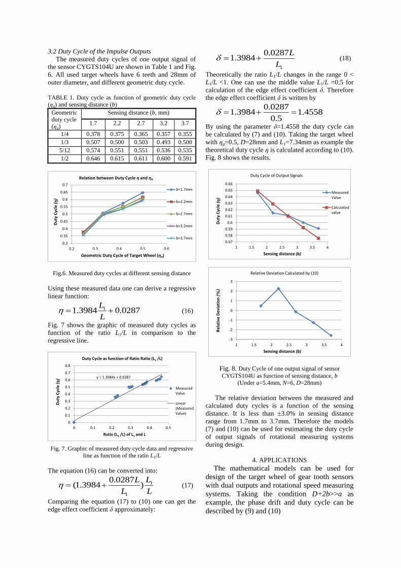
3.2 Duty Cycle of the Impulse Outputs
The measured duty cycles of one output signal of
the sensor CYGTS104U are shown in Table 1 and Fig.
6. All used target wheels have 6 teeth and 28mm of
outer diameter, and different geometric duty cycle.
TABLE 1. Duty cycle as function of geometric duty cycle
(ηg) and sensing distance (b)
Geometric
duty cycle
(ηg)
Sensing distance (b, mm)
1.7 2.2 2.7 3.2 3.7
1/4 0.378 0.375 0.365 0.357 0.355
1/3 0.507 0.500 0.503 0.493 0.500
5/12 0.574 0.551 0.551 0.536 0.535
1/2 0.646 0.615 0.611 0.600 0.591
0.3
0.35
0.4
0.45
0.5
0.55
0.6
0.65
0.7
0.2 0.3 0.4 0.5 0.6
b=1.7mm
b=2.2mm
b=2.7mm
b=3.2mm
b=3.7mm
Du
ty C
ycle
(η)
Relationship between η and ηg
Gemetric Duty Cycle of Target Wheel
Fig.6. Measured duty cycles at different sensing distance
Using these measured data one can derive a regressive
linear function:
0287.03984.1 1 L
L (16)
Fig. 7 shows the graphic of measured duty cycles as
function of the ratio L1/L in comparison to the
regressive line.
y = 1.3984x + 0.0287
0
0.1
0.2
0.3
0.4
0.5
0.6
0.7
0.8
0 0.1 0.2 0.3 0.4 0.5
MeasuredValue
Linear(MeasuredValue)
Du
ty C
ycle
(η)
Duty Cycle as function of Ratio Ratio (L1 /L)
Ratio (L1 /L) of L1 and L
Fig. 7. Graphic of measured duty cycle data and regressive
line as function of the ratio L1/L
The equation (16) can be converted into:
L
L
L
L 1
1
)0287.0
3984.1( (17)
Comparing the equation (17) to (10) one can get the
edge effect coefficient δ approximately:
1
0287.03984.1
L
L (18)
Theoretically the ratio L1/L changes in the range 0 <
L1/L <1. One can use the middle value L1/L =0.5 for
calculation of the edge effect coefficient δ. Therefore
the edge effect coefficient δ is written by
4558.15.0
0287.03984.1
By using the parameter δ=1.4558 the duty cycle can
be calculated by (7) and (10). Taking the target wheel
with ηg=0.5, D=28mm and L1=7.34mm as example the
theoretical duty cycle η is calculated according to (10).
Fig. 8 shows the results.
0.57
0.58
0.59
0.6
0.61
0.62
0.63
0.64
0.65
0.66
1 1.5 2 2.5 3 3.5 4
MeasuredValue
Calculatedvalue
Duty Cycle of Output Signals
Sensing distance (b)
Du
tyC
ycle
(η)
-3
-2
-1
0
1
2
3
1 1.5 2 2.5 3 3.5 4
Relative Deviation Calculated by (10)
Sensing distance (b)
Rel
ativ
e D
evia
tio
n (%)
Fig. 8. Duty Cycle of one output signal of sensor
CYGTS104U as function of sensing distance, b
(Under a=5.4mm, N=6, D=28mm)
The relative deviation between the measured and
calculated duty cycles is a function of the sensing
distance. It is less than ±3.0% in sensing distance
range from 1.7mm to 3.7mm. Therefore the models
(7) and (10) can be used for estimating the duty cycle
of output signals of rotational measuring systems
during design.
4. APPLICATIONS
The mathematical models can be used for
design of the target wheel of gear tooth sensors
with dual outputs and rotational speed measuring
systems. Taking the condition D+2b>>a as
example, the phase drift and duty cycle can be
described by (9) and (10)
Geometric Duty Cycle of Target Wheel (ηg)
Relation between Duty Cycle η and ηg

In this case, if the outer diameter, D, the
distances, a and b, are known the number of teeth
N of the target wheel can be determined by
a
bDN
360
)2( (20)
and the addendum arc width L1 can be calculated by
N
bDL
)2(1
(21)
In order to get a suitable phase drift ΔФ =90° and a
duty cycle η=0.5 for a rotational speed measuring
system the recommended number of teeth N and the
addendum arc width L1 should be determined by
a
bDN
4
)2(
(22)
and
N
bDL
2
)2(1
(23)
In comparison with (11) the effective tooth arc pitch L
should be 4 times of distance between the two
detectors, i.e. L=4a.
As example one can determine the parameters of
target wheel of a rotational speed measuring system
under using the Hall Effect gear tooth sensor
CYGTS104U [3]. For D=28mm, b=3mm and
a=5.4mm one obtains the number of teeth N=5 and the
addendum arc width L1 =7.34mm under using the edge
effect coefficient δ=1.4558. The geometric tooth arc
pitch Lg is equal to 17.59mm according to (14)
In the same way one can also determine the
outer diameter, D, of the target wheel and the
sensing distance, b, etc. Further information
about this topic will be discussed in another
paper.
5. CONCLUSIONS
The proposed mathematical models are tested by
Hall Effect gear tooth sensor CYGTS104U and speed
measuring systems. From the experiment results one
can draw the following conclusions:
The phase drift between the output signals can be
determined by using the models (5) and (9). The
relative deviation of the parameter calculation is
within ±3.0%.
The edge effect coefficient δ of target wheel can be
estimated by linear regression under using the
measuring data of duty cycles of output signals at
different geometric duty cycle of the target wheel.
The duty cycle of the output signals can be
calculated by the model (7) and (10). The relative
deviation is also within ±3.0%.
The mathematical models proposed in this paper
can be used for determining the parameters of the
target wheel and other parameters of the rotational
speed measuring systems
The models are very usable for analysing gear
tooth sensors with dual impulse outputs and very
helpful and effective for the design and develop-
ment of rotational speed measuring systems.
The further works should be concentrated on the
model-based design of the rotational speed sensors
and measuring systems in order to optimize the
measuring system and save the design time and
development costs.
REFERENCES [1] N.V. KIRIANAKI, S.Y. YURISH, “High Precision,
Wide Speed Range Rotation Sensing with UFDC-1“ ,
Sensors & Transducers Magazine (S&T e-Digest),
Vol.59, Issue 9, September 2005, pp.426-431
[2] Allegro MicroSystems, Inc., “ATS617LSG, Dynamic,
Self-Calibrating, Peak-Detecting, Differential Hall
Effect Gear Tooth Sensor IC”, data sheet,
http://www.allegromicro.com
[3] J.-G. Liu, “Hall Effect Gear Tooth Sensors CYGTS104”,
data sheet, ChenYang Technologies GmbH and Co. KG.,
http://www.hallsensors.de/CYGTS104.pdf
[4] N. PATRASCOIU, A. POANTA, A. TOMUS and B.
SOCHIRCA, Virtual instrumentation used for
displacement and angular speed measurements,
INTERNATIONAL JOURNAL OF CIRCUITS,
SYSTEMS AND SIGNAL PROCESSING, Issue 2,
Volume 5, 2011, pp. 168-175
[5] Melexis, MLX90254 Differential Dynamic Hall Effect
Sensor, data sheet, http://www.melexis.com
[6] Infineon Technologies, TLE4921-5U Dynamic
Differential Hall Effect Sensor IC, data sheet,
http://www.infineon.com
[7] Pascal Desbiolles and Achim Friz, Development of High
Resolution Sensor Element MPS40S and Dual Track
Magnetic Encoder for Rotational Speed and Position
Measurement, NTN TECHNICAL REVIEW No.75,
2007, pp. 36-41
[8] Computer Optical Products, Inc., Optical Encoder
Applications, www.opticalencoder.com
[9] Baumer Hübner GmbH, MHGE 800 B5 G Magnetic
Rotary Encoder, www.baumerhuebner.com
[10] Honeywell, GT1 Series Hall Effect Gear Tooth Sensors,
http://honeywell.com/Pages/Home.aspx
Authors: Dr.-Ing. habil. Ji-Gou Liu, general and technical
manager, ChenYang Technologies GmbH & Co. KG.,
Markt Schwabener Str. 8, 85464 Finsing, Germany,
Tel.: +49-8121-2574100, Fax: +49-8121-2574101,
[email protected], http://www.chenyang-
ism.com. Dr. Liu is visiting prof. of University of Shanghai
for Science and Technology.
M.sc. Zhe Zheng, doctoral candidate, University of
Shanghai for Science and Technology (USST), Jungong
Load 516, 200093 Shanghai, P.R. China,
[email protected]. Mr. Zheng does his research &
development work at ChenYang Technologies GmbH & Co.
KG since September 1, 2010