Rules for Building and Classing Offshore Installations - 1997

TECHNICAL REPORT
PETROLEUM SAFETY AUTHORITY NORWAY (PSA)
MATERIAL RISK - AGEING OFFSHORE
INSTALLATIONS
REPORT NO. 2006-3496 REVISION NO. 0
DET NORSKE VERITAS

DET NORSKE VERITAS
Report No: 2006-3496, rev. 0
TECHNICAL REPORT
Table of Content Page
1 INTRODUCTION ....................................................................................................... 1
2 DEGRADATION MECHANISMS............................................................................. 3 2.1 Degradation mechanisms 3 2.1.1 Erosion 3 2.1.2 Corrosion 3 2.1.2.1 General 3 2.1.2.2 External corrosion 4 2.1.2.3 Hydrogen Induced Stress Cracking 5 2.1.2.4 Internal corrosion 5 2.1.3 Fatigue 7 2.1.4 Corrosion fatigue 8 2.2 References 8
3 LOAD BEARING STRUCTURES ............................................................................. 9 3.1 Concrete 9 3.1.1 Introduction 9 3.1.2 Main degradation mechanisms 9 3.1.3 History 11 3.1.4 State of the Art on R&D 14 3.1.5 Recommendations 15 3.1.6 References 15 3.2 Steel 18 3.2.1 Introduction 18 3.2.1.1 Main principles of classification 18 3.2.2 History 18 3.2.3 Main degradation mechanisms 20 3.2.3.1 Corrosion 20 3.2.3.2 Present situation – Ageing rigs 20 3.2.3.3 Fatigue 22 3.3 References 24
4 SUBSEA PIPELINES................................................................................................ 25 4.1 Introduction 25 4.2 History 25 4.3 Main degradation mechanisms 26 4.4 Failure modes 27 4.5 Ensuring integrity of subsea pipelines 28 4.5.1 Process- and product control 29 4.5.2 Corrosion Monitoring 29 4.5.3 External Inspections 30 4.5.4 Internal Inspection 30
Page i Reference to part of this report which may lead to misinterpretation is not permissible.
AACAACDW.doc
DET NORSKE VERITAS
Report No: 2006-3496, rev. 0
TECHNICAL REPORT
4.5.5 Hydrostatic pressure testing 31 4.6 “Corrosion Zones” associated with external corrosion. 31 4.7 Technology Status 33 4.8 References 34
5 SUBSEA EQUIPMENT ............................................................................................ 35 5.1 Introduction 35 5.2 Template 35 5.2.1 Workmanship 35 5.2.2 Degradation mechanism 35 5.2.3 Inspection programme 36 5.3 Manifold 36 5.3.1 Workmanship 36 5.3.2 Degradation mechanism 37 5.3.3 Inspection programme 38 5.4 Subsea Christmas tree (XT) 38 5.4.1 Workmanship 38 5.4.2 Degradation mechanism 39 5.4.3 Inspection program 39 5.5 References 40
6 DRILLING AND WELLS......................................................................................... 41 6.1 Introduction 41 6.2 History 41 6.3 Main degradation mechanisms 41 6.4 Drilling system and well system 41 6.4.1 Pipe handling 43 6.4.2 Main hoisting system 43 6.4.3 Control systems 43 6.4.4 Iron Roughneck and pipe racking system 43 6.4.5 Steel wire ropes 44 6.4.6 Sealed machinery 44 6.4.7 Drill string 44 6.4.8 Drilling riser 45 6.5 Blow Out Preventer (BOP) 45 6.6 Subsea Wellhead 46 6.6.1 Workmanship 46 6.7 Conductors 46 6.7.1 Workmanship 47 6.8 Production casing in wells 47 6.9 High pressure tubing and manifolds for circulation of drill mud 48 6.10 Recertification of well control equipment 48 6.11 References 49
Page ii Reference to part of this report which may lead to misinterpretation is not permissible.
AACAACDW.doc

DET NORSKE VERITAS
Report No: 2006-3496, rev. 0
TECHNICAL REPORT
7 MOORING SYSTEM................................................................................................ 50 7.1 Introduction 50 7.2 Fairleads and chain stoppers 50 7.3 Chain 51 7.4 Recertification of chain 54 7.5 Synthetic fibre ropes 54 7.6 Steel wire ropes 55 7.7 References 58
Appendix A Summary
Page iii Reference to part of this report which may lead to misinterpretation is not permissible.
AACAACDW.doc

DET NORSKE VERITAS
Report No: 2006-3496, rev. 0
TECHNICAL REPORT
1 INTRODUCTION On request from Petroleum Safety Authority Norway (PSA), DNV has prepared technological summaries regarding material risk on ageing equipment and installations in the oil and gas industry offshore. The report contains an introductory section on degradation mechanisms in general, followed by five sections containing technological reviews of metallic materials with respect to degradation mechanisms and failure modes, and its effect on ageing installations and equipment. Five areas, which are exposed to degradation of materials due to ageing, are covered in the report:
Load bearing structures (concrete and steel) Subsea pipelines Subsea equipment Drilling and wells Mooring system
Specific structures, systems or equipment have been selected from each of the above mentioned areas, and a technological review has been given based on in-house experience. This contains an evaluation of:
Failure modes introduced by the degradation mechanism Occurrence of the degradation mechanism Limitations of the material introduced by the degradation mechanism Uncertainty of the material when degraded Future challenges of the material related to the degradation mechanism Effect of the degradation mechanism on the robustness of the installation
A summary of the degradation mechanisms and failure modes relevant within the five areas listed above, is presented in Appendix A. The authors and the persons who have performed the verification for each section are listed below:
1. Degradation mechanisms a. Author: Kari Lønvik, Bente H. Leinum, Espen B. Heier b. Work verified by: Tomas Sydberger, Knut Strengelsrud
2. Load bearing structures, concrete a. Author: Andrzej Serednicki, Prof. Odd E. Gjørv (NTNU) b. Work verified by: Prof. Odd E. Gjørv (NTNU), Andrzej Serednicki
3. Load bearing structures, steel a. Author: Tor Myhre b. Work verified by: Svein Flogeland
4. Subsea pipelines a. Author: Bente H. Leinum b. Work verified by: Kari Lønvik
Page 1 Reference to part of this report which may lead to misinterpretation is not permissible.
AACAACDW.doc

DET NORSKE VERITAS
Report No: 2006-3496, rev. 0
TECHNICAL REPORT
5. Subsea equipment a. Author: Bjørn Søgård b. Work verified by: Rolf Benjamin Johansen
6. Drilling and wells a. Author: Leif Halvor Moen b. Work verified by: Axel Stang Lund, Lars Tore Haug
7. Mooring system a. Author: Bjørn E. Sogstad b. Work verified by: Siril Okkenhaug
Images used are DNV property unless otherwise indicated.
Page 2 Reference to part of this report which may lead to misinterpretation is not permissible.
AACAACDW.doc

DET NORSKE VERITAS
Report No: 2006-3496, rev. 0
TECHNICAL REPORT
2 DEGRADATION MECHANISMS Relevant degradation mechanisms are presented in Section 2.1.
All mechanisms, which are relevant for the five areas mentioned in Section 1, are included in this chapter.
2.1 Degradation mechanisms A degradation mechanism is here defined as a disintegration of a metallic material due to the impact of the operating environment and forces. Degradation can be due to erosion, corrosion or stresses induced by cyclic/dynamic loads and other specific environmental impacts. The degradation mechanism can result in metal loss (as uniform or localised attacks) or cracking (e.g. fatigue, stress corrosion cracking, embrittlement). Degradation mechanisms related to metal loss and fatigue are typically time dependent (e.g. wall thinning), whilst cracking mechanisms are of more abrupt nature.
2.1.1 Erosion Erosion can be defined as physical removal of surface material due to numerous individual impacts of solid particles, liquid droplet or implosion of gas bobbles (cavitation). Erosion is a time dependent degradation mechanism, but can sometimes lead to very rapid failures.
In its mildest form, erosive wear appears as a light polishing of the upstream surfaces, bends or other stream-deflecting structures. In its worst form, considerable material loss can be obtained.
2.1.2 Corrosion 2.1.2.1 General Corrosion is caused by a chemical (or electrochemical) reaction between a metal and its environment that produces a deterioration of the material and sometime its properties. For corrosion to occur, the following basic conditions must be fulfilled:
• metal surface exposed to environment (bare steel in physical contact with the environment)
• electrolyte (e.g. water containing ions, the electrolyte must be able to conduct current) • an oxidant (a chemical component causing corrosion (e.g. oxygen, carbon dioxide)
If one of these conditions is not present, no corrosion will occur.
Table 2-1 summarises prospective corrosion mechanisms for subsea oil and gas production equipment.
The presence of organic acids and sulphur containing compounds (e.g. elemental sulphur) may aggravate the corrosion in the system.
Page 3 Reference to part of this report which may lead to misinterpretation is not permissible.
AACAACDW.doc

DET NORSKE VERITAS
Report No: 2006-3496, rev. 0
TECHNICAL REPORT
Table 2-1 Internal and external corrosion mechanisms in a subsea oil and gas production environment.
Corrosion
Mechanism
External Internal Chemical reaction Time dependency
O2-corrosion X X 2Fe + H2O + 3/2O2 → 2FeO(OH)(s) (“rust”)
Time dependent
CO2-corrosion 1)
(sweet corrosion) NA X Fe + H2O + CO2 → FeCO3(s) + H2
Time dependent
Microbiologically induced corrosion (MIC)
X X Fe + “bacteria related oxidant” → Fe2+
Time dependent/ abrupt nature
Sulphide stress cracking (SSC) (corrosion due to H2S)
NA2) X 2H+ → H⋅(ads) H⋅(ads) → H2(ads) (inhibited by H2S) H⋅(ads) → H⋅(abs)
Abrupt nature
1) Not anticipated on corrosion resistant alloys 2) Under certain conditions high levels of H2S might occur in the seabed, however, such condition is not anticipated to occur on the Norwegian shelf.
2.1.2.2 External corrosion External corrosion is for most submerged equipment controlled by the use of an external corrosion coating and a cathodic protection (CP) system. The design of the CP system is dependent on the design life of the equipment and the type and quality of the external coating system in question.
Some subsea components may not be provided with a CP-system (e.g. for chains) or CP will not be efficient due to shielding (e.g. water filled hollow profiles). For carbon steel components a corrosion allowance (CA) must then be added. The CA that must be added will depend on the availability of oxygen (oxidant). For areas with limited access of oxygen, such as within hollow profiles of structural steel, the corrosion rate will be low and a moderate CA is tolerable, whereas for instance chains that are freely exposed to seawater, a higher corrosion rate must be accounted for. The CA is normally determined as a part of the design and is based on the specified design life of the component.
Certain corrosion resistant alloys (CRA’s) and titanium are resistant to seawater corrosion under North Sea ambient seawater conditions and can be used without cathodic protection.
Page 4 Reference to part of this report which may lead to misinterpretation is not permissible.
AACAACDW.doc

DET NORSKE VERITAS
Report No: 2006-3496, rev. 0
TECHNICAL REPORT
2.1.2.3 Hydrogen Induced Stress Cracking Cathodic protection may be detrimental for some materials due to Hydrogen Induced Stress Cracking (HISC). Hydrogen Induced Stress Cracking (HISC) is caused by a combination of load/stress and hydrogen embrittlement (HE) caused by the ingress of atomic hydrogen into the metal matrix formed at the steel surface due to the cathodic protection (CP). High strength steel (SMYS > 500 MPa) and some corrosion resistance materials (13Cr-steel and duplex stainless steels) are susceptible to HISC, see /1, 2, 3, 4/. Solution annealed austenitic stainless steels and nickel based alloys are generally considered immune to HISC. DNV RP B401 Sec. 5.5 /1/ gives recommendations with regards to materials maximum hardness level and the specified minimum yield strength for safe combinations with CP. Bolts in martensitic steels heat treated to SMYS up to 720 MPa and maximum hardness level of 350HV (ASTM A182 grade B7 and ASTM A320 grade L7) have documented compatibility with CP (see also Norsok M-001 Sec. 5.6 /5/). Factors influencing HISC of duplex stainless steel have been recapitulated in a draft version of DNV RP F-112 /2/ with recommendation for design criteria based on best practice and on today’s knowledge (strain/stress criteria). HISC is abrupt of nature and it is expected to occur during the first years of the installations design life if the conditions are ideal.
2.1.2.4 Internal corrosion CO2-corrosion; CO2-corrosion or sweet corrosion is not anticipated for corrosion resistant materials (e.g. 13Cr, 316L, 22Cr, 25Cr, Alloy 625). Carbon steel, however, will be subjected to CO2-corrosion. The corrosion rate is dependent on the partial pressure of CO2, the temperature, the flow regime and the water in-situ pH. The corrosion takes the form of localised- (‘pitting’), uniform- and grooving- (e.g. longitudinal, transverse) attacks and is a time dependent degradation mechanism. CO2-corrosion can be mitigated by the use of corrosion inhibitors and/or by pH- stabilisation of the process fluid (primarily applicable for pipelines).
O2-corrosion; Internal corrosion due to the presence of O2 is in principle not expected in oil and gas production systems since no oxygen shall be present in the process medium. Ingress of oxygen may increase the corrosion in the system.
Water used for water injection can be either deaerated or aerated, which will have an impact on the corrosivity. Due to the removal of oxygen in deaerated water, the corrosion rate of carbon steel will be low, whereas in systems carrying aerated water a higher corrosion rate must be anticipated. Oxygen corrosion is a time dependent corrosion mechanism and takes principally the form of uniform corrosion, but localised attacks may also occur (‘pitting’).
Corrosion resistance alloys (CRA’s) and titanium can be used for seawater service but there are certain design limitations regarding the use of such materials (e.g. temperature, presence of crevices, chlorination etc.). Corrosion of CRA takes the form of localised attack. Unfortunate combination of material and operating environment will for most cases result in a corrosion failure during the initial phase of an installation’s life.
Page 5 Reference to part of this report which may lead to misinterpretation is not permissible.
AACAACDW.doc

DET NORSKE VERITAS
Report No: 2006-3496, rev. 0
TECHNICAL REPORT
Environmental cracking due to H2S; Corrosion due to the presence of H2S is primarily related to environmental cracking (i.e. sulphide stress cracking (SSC)). Both carbon steel and CRA’s are susceptible to SSC. The risk for SSC is dependent on the partial pressure of the H2S, the in-situ pH-value, total tensile stress, chloride ion concentration, presence of other oxidant etc. (for details reference is made to ISO-15156). Below a critical partial pressure of H2S no SSC is expected to occur. However, for partial pressures above this limit there is an increasing risk for SSC and the environmental condition is termed as sour. The resulting failure mode is cracking and it is of abrupt nature. SSC is controlled by specification of the material properties (e.g. hardness) and the manufacturing process. For susceptible materials, environmental cracking is expected to occur during the initial phase of production and is not expected to have a time dependent development similar to ‘sweet’ corrosion.
Older petroleum installations may experience a souring of the wells (the produced amount of H2S increases) and the production environment turns from sweet to sour. The risk for environmental cracking should for such cases be subjected to evaluations with respect to the material properties and the new service condition.
Microbiologically Induced Corrosion (MIC); The two best known bacteria of concern for the oil and gas industry are the sulphate reducing bacteria (SRB) and the acid producing bacteria (APB). They may live synergistically in colonies attached to the steel surface, where the SRB bacteria live beneath the APB colony. SRB bacteria live in oxygen-free environments and use sulphate ions in the water as a source of oxygen. H2S is produced as a waste product from the SRB, producing a corrosive environment locally in connection with the colony of bacteria. The risk for obtaining MIC will depend on the availability of nutrients, temperature, water and flow condition. MIC takes the form of localised attack causing a pinhole leakage of a pipe. High corrosion rate can be anticipated (>1 mm/year) if the conditions are ideal. MIC has been obtained in oil production systems as well as on steel exposed (e.g. anchor chains) to seabed sediments. The location of MIC is difficult to predict. For pipeline systems, treatments with biocide may be effective as a preventive measure. A common source for bacteria in a closed system is seawater. Use of untreated seawater for hydro testing should therefore be avoided.
Galvanic corrosion; Galvanic corrosion may occur when there is an electrical coupling between dissimilar metals. The least noble material (anode) will be sacrificed on behalf of the noblest material (cathode). The extent of accelerated corrosion resulting from galvanic coupling is affected by the electrochemical potential difference between metallic couple, the nature of the environment (corrosivity) and the area ratio of anodic- and cathodic areas (small anode to cathode area ration is unfavourable). Galvanic corrosion is a time dependent form of corrosion and result in a uniform corrosion attack. The possibility for obtaining galvanic corrosion should be evaluated during the design phase. For cases where a galvanic couple is inevitable, a distance spools of a non-conducting material can be installed or installation of a galvanic spool with sufficient wall thickness where the material is intended to corrode (i.e. sacrificial spool).
Page 6 Reference to part of this report which may lead to misinterpretation is not permissible.
AACAACDW.doc
DET NORSKE VERITAS
Report No: 2006-3496, rev. 0
TECHNICAL REPORT
2.1.3 Fatigue Fatigue failures occur in parts which are subjected to alternating, or fluctuating (other used terms are dynamic or cyclic), stresses. Fatigue cracking is usually initiated at stress raisers such as sharp geometric transitions, welds, notches or internal material flaws such as slags, cracks (e.g. quench cracks or weld lack of fusion defects). A minute crack starts at a localized spot and gradually spreads over the cross section until the component/member fails due to overloading of the remaining cross section area.
Fatigue results in an almost brittle-appearing fracture, with no gross deformation at the fracture. Crack propagation may be divided into stages, the most important being “initiation” and “propagation”. Depending on the material, the stress level and eventual environmental impact - initiation or propagation may be the stage constituting the main part of the lifetime of the component/member.
Fatigue failure is caused by a critical localized tensile stress which is very difficult to evaluate and therefore design for fatigue failure is based primarily on empirical relationships using nominal stresses. A fatigue failure can usually be recognized from the appearance of the fracture surface, which shows a smooth region, due to the fatigue crack propagation through the section (being more or less insensitive to the microstructure and hence orientated perpendicular to the principle direction of the applied stress), and a rough region, where the member has failed when the remaining cross section was no longer able to carry the load. Frequently the progress of the fracture is indicated by a pattern of parallel lines, or “beach marks”, progressing inward from the point of initiation of the failure.
Three basic factors are necessary to cause fatigue failure. These are (1) a maximum tensile stress of sufficiently high value, (2) a large enough variation or fluctuation in the applied stress, and (3) a sufficiently large number of cycles of the applied stress. In addition, there are a host of other variables, such as stress concentration (e.g. geometric transitions), corrosion (localised corrosion e.g. preferential weld corrosion), temperature (stresses induced by linear thermal expansion or differences in thermal expansion coefficients between different materials), overload (over-torque of bolts), metallurgical structure (e.g. direction of texture vs. direction of applied stress), residual stresses (welding or forming residual stresses), and combined stresses, which tend to alter the conditions for fatigue.
Recommendations for design when considering fatigue resistance of offshore structures are given in DNV-RP-C203 /6/. This recommended practice contains among other things a collection of fatigue resistance (S-N) curves developed for different configurations (e.g. types of welded joints), surface finish and environmental conditions. For some of the curves assumptions regarding defect sizes, and hence corresponding NDT requirements are given.
Crack propagation may be both adversely or favourably affected by variable amplitude loading. Intermittent high stresses may create large plastic zones with “residual” compressive stresses ahead of the crack toe and hence retard crack growth.
Page 7 Reference to part of this report which may lead to misinterpretation is not permissible.
AACAACDW.doc
DET NORSKE VERITAS
Report No: 2006-3496, rev. 0
TECHNICAL REPORT
2.1.4 Corrosion fatigue On a general level fatigue is affected by environmental conditions and in particular by corrosion. HISC and sour service conditions, as described in Section 2.1.2.2 and 2.1.2.3, respectively, may facilitate fatigue crack initiation. Metal loss by corrosion will generally enhance crack growth, but under reversed loading conditions (tension – compression) corrosion products may reduce the “impact” of the total stress range due to “crack closure”.
Corrosion fatigue occurs in metals as a result of the combined action of cyclic stress and a corrosive environment. For a given material, the fatigue strength (or fatigue life at a given maximum stress value) generally decreases in the presence of an aggressive environment.
When corrosion and fatigue occur simultaneously, the chemical attack accelerates the rate at which fatigue cracks propagate. Materials which show a definite fatigue limit when tested in air at room temperature show no indication of a fatigue limit when the test is carried out in a corrosive environment.
Corrosion fatigue crack growth might be influenced by many variables, such as those listed in Section 2.1.3, but also by environmental variables (gaseous or liquid environment, partial pressure of damaging species in gaseous environments, temperature, pH).
A number of methods are available for minimizing corrosion fatigue damage: - The choice of material for this type of service should be based on its corrosion
resistant properties rather than the conventional fatigue properties (ex. stainless steel over heat-treated steel)
- Protection of the metal from contact with the corrosive environment by metallic or non-metallic coatings (provided that the coating does not become ruptured from the cyclic strain)
- Addition of a corrosion inhibitor in closed systems to reduce the corrosive attack - Elimination of stress concentrators by careful design
2.2 References
/1/ DNV-RP-B401 (2005), Cathodic protection design
/2/ Draft-DNV RP-F112, Design of duplex stainless steel subsea equipment exposed to cathodic protection
/3/ Thierry Cassagne and Freddy Busschaert, ”A review on Hydrogen Embrittlement of duplex stainless steels”, NACE Paper 05098 cor
/4/ E. B. Heier and R. B. Johansen “North Sea Failures of 13Cr flowlines: Consequences for Future Application”, Proc. of SEM X, Costa Mesa, California, June 2004.
/5/ Norsok M-001 rev. 4, Materials selection
/6/ DNV-RP-C203 (2005) Fatigue design of offshore steel structures
Page 8 Reference to part of this report which may lead to misinterpretation is not permissible.
AACAACDW.doc

DET NORSKE VERITAS
Report No: 2006-3496, rev. 0
TECHNICAL REPORT
3 LOAD BEARING STRUCTURES
3.1 Concrete 3.1.1 Introduction When the first concept of fixed concrete structures for offshore oil and gas exploration and production in the North Sea was introduced in the late 1960´s, the offshore technical community showed much scepticism. At the same time, however, the results of a comprehensive field investigation of more than 200 existing conventional concrete sea structures such as bridges and harbour structures along the Norwegian coastline were published /1/. The overall good performance of these structures recorded even after a service life of 50-60 years contributed to convincing the technical community that also concrete could be a reliable construction material for oil and gas installations in the North Sea. However, the appearance of corrosion on embedded reinforcement steel that typically took place on the conventional concrete sea structures already after a service period of 5-10 years was not acceptable. Therefore, in order to gain acceptance for the first offshore concrete platform in the North Sea, both increased concrete qualities and concrete covers beyond the requirements of current concrete codes were required. Secondly, much stricter programs for QA/QC compared to the existing design and construction practice had to be introduced.
Already during the construction of Ekofisk Tank, the first edition of “Recommendations for design and construction of concrete sea structures” was published by the international organization for prestressed concrete /2/. Thereafter, both Norwegian Petroleum Directorate in their Regulations /3/ and Det Norske Veritas /4/ in their Rules had adopted new and stricter durability requirements for fixed offshore concrete structures.
After the first breakthrough for use of concrete in developing the Ekofisk oil field, a rapid development took place. During the period from 1973 to 1995 altogether 28 major concrete platforms containing more than 2.5 million cubic meters of concrete were installed in the North Sea. Several of these installations are now successively approaching the intended service life of 25-30 years.
Considering the harsh and hostile marine environment in the North Sea, the question has been raised on how these concrete structures have performed so far. As there is need for a continued service of the installations beyond the service life originally designed, the question also has been raised for how long these fixed concrete structures can be safely operated.
3.1.2 Main degradation mechanisms Although deteriorating mechanisms such as chemical seawater attack, freezing and thawing, and expansive alkali reactions all present some potential durability problems for offshore concrete structures, it is relatively easy to avoid such problems by taking the necessary precautions at an early stage of planning, designing and construction. For oil containment vessels, aggressive bacteriological environment may also represent a potential problem of concrete degradation. For a dense, high-quality concrete, however, such a degradation should not represent any durability problem.
Page 9 Reference to part of this report which may lead to misinterpretation is not permissible.
AACAACDW.doc
DET NORSKE VERITAS
Report No: 2006-3496, rev. 0
TECHNICAL REPORT
The concrete platforms located in the Norwegian Sector of the North Sea were designed and constructed in accordance with the requirements specified in /2, 3, 4/, and reflected the current “state-of-the-art” which in the main are still relevant and acceptable.
For concrete structures in the marine environment, extensive experience demonstrates, however, that it is not the disintegration of the concrete itself but rather the electrochemical corrosion of embedded steel reinforcement and pre-stressed tendons which poses the most critical and greatest threat to the durability and long-term performance of the structures /5/. As long as it is possible to prevent or retard the chlorides penetration into concrete, all embedded steel is very efficiently protected from corrosion by electrochemical passivation of the highly alkaline concrete.
The high alkalinity of concrete may be neutralized by a reaction between the atmospheric carbon dioxide and the calcium hydroxide solution in the concrete. Such a carbonation process will also impair the passivity of embedded steel causing steel corrosion. For a dense, high-quality concrete in a moist environment, however, carbonation is limited to a very thin surface layer and does not represent real problem to marine concrete structures.
As soon as the chlorides from seawater have reached embedded reinforcement and prestressed steel and the passivity of the steel is broken, a complex system of galvanic cells will develop causing electrochemical corrosion of the steel /6/. The rate of embedded steel corrosion will then primarily be controlled by the availability of dissolved oxygen in the cathodic areas and the electrical resistivity of the concrete. The area ratio of the depassivated parts (anodic areas) and the passive parts (cathodic areas) in the galvanic cells is also an important factor for the corrosion rates. The electrical resistivity of concrete in moist marine environment is normally so low that it does not become the governing factor for the electrochemical corrosion process /7/.
Both in the tidal and in the splash zones of concrete sea structures, oxygen is available in plenty, so that a high corrosion rate can take place in the zones /8/. Only for the constantly submerged parts of high quality concrete structures, the availability of oxygen is generally so low that an electrochemical corrosion of embedded steel does not represent any practical problem /9/.
In all concrete structures, a certain amount of cracks in the concrete cover may freely expose parts of the embedded steel. In a moist marine environment, however, crack widths of up to 0.5 mm would normally not represent any corrosion problems /10/. For static cracks in submerged parts of the structure, even wider cracks may be tolerated due to a filling up of the cracks by various chemical reaction products (Calcareous depositions consisting mainly of magnesium hydroxide, calcium carbonate and corrosion products which block up the cracks and reduce rate of steel corrosion. The process is known in the literature as “self-healing of cracks”). For dynamic cracks, however, wider (in excess of 0.5 – 0.6 mm) cracks may represent a potential corrosion problem /11/.
In the submerged part of offshore concrete structures, a variety of freely exposed metallic components, such as pipes, penetration sleeves, clamps, brackets, supports and other fixtures are in metallic connection with the embedded reinforcement steel and may represent a special corrosion problem /12/. In such a case, the freely exposed metallic components represent small anodic areas in metallic connection with huge cathodic areas of the embedded reinforcement steel acting as catchments areas for oxygen. In order to control this galvanic corrosion problem, an effective cathodic protection system for all freely exposed metallic components is essential. Normally, such a cathodic protection has been based on sacrificial anodes.
Page 10 Reference to part of this report which may lead to misinterpretation is not permissible.
AACAACDW.doc

DET NORSKE VERITAS
Report No: 2006-3496, rev. 0
TECHNICAL REPORT
3.1.3 History Extensive surveying programs both above and below water are regularly being carried out for all offshore concrete structures in the North Sea, however no recent information on the current status of these structures is available for general public. In a State of the Art report from 1994 /13/, very little corrosion problems on embedded steel was reported; the most serious problems were related to accidental loads from ships and falling items. More detailed inspections of eleven of the oldest concrete structures installed during 1973–78 and reported in 1982, also showed their generally good conditions /14/. Inspection of the concrete platforms on the Statfjord and Gullfaks Oil Fields in 1992 also reported a generally good condition of the concrete /15/.
After 20 years of service, regular inspections of the relatively wide concrete cracks found at the foundation of Frigg CDP-1 Platform had revealed no serious corrosion in the cracked concrete /16/. After 18 years of service, corrosion monitoring based on embedded steel tubes in the Frigg TCP-2 Platform did neither report any steel corrosion /16/. Also laboratory-based investigations have shown that the risk of steel corrosion in cracked submerged concrete appears to be less severe than what originally expected /10, 11/.
Only for a few of the concrete platforms in the North Sea, more systematic investigations of chloride penetration have been carried out. All of these investigations clearly demonstrate that a certain rate of chloride penetration does take place, but only at a slower rate compared to that typically observed on conventional concrete structures /17/. Figure 3-1-1 and 3-1-2 show the chloride penetration into the concrete of Statfjord A Platform and Ekofisk Tank after 8 and 17 years of exposure, respectively. Figure 3-1-3 and 3-1-4 show the chloride penetration into the concrete of Brent B and Brent C Platforms, respectively, after 18-20 years of exposure. For Oseberg A Platform, where the concrete cover was partly less than what had been specified, serious corrosion problems occurred already at an early stage of operation. For this structure, repairs in the form of cathodic protection were carried out in 1998 /21/.
Figure 3-1-1 Chloride penetration into concrete of Statfjord A Platform (1977) after 8 years of exposure /18/.
Page 11 Reference to part of this report which may lead to misinterpretation is not permissible.
AACAACDW.doc

DET NORSKE VERITAS
Report No: 2006-3496, rev. 0
TECHNICAL REPORT
Figure 3-1-2 Chloride penetration into concrete of Ekofisk Tank (1973) after 17 years of exposure /19/.
0
0,05
0,1
0,15
0,2
0,25
0,3
0,35
0 10 20 30 40 50 60 70
Distance from the exposed surface (mm)
Chl
orid
e co
ncen
tratio
n (%
Cl a
s w
eigh
t of c
oncr
ete)
elevation: + 14.4 melevation: + 7.83 melevation: -11.5 m
Figure 3-1-3 Chloride penetration into concrete of Brent B Platform (1975) after 20 years of exposure /20/.
Page 12 Reference to part of this report which may lead to misinterpretation is not permissible.
AACAACDW.doc
DET NORSKE VERITAS
Report No: 2006-3496, rev. 0
TECHNICAL REPORT
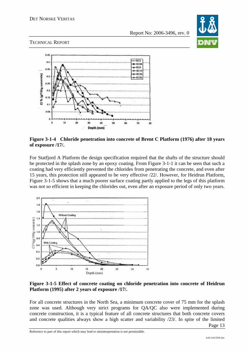
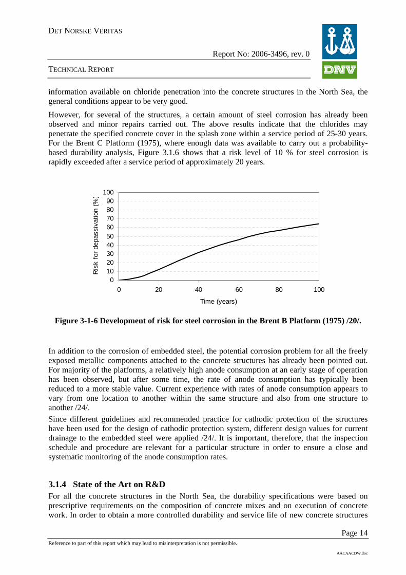
Figure 3-1-4 Chloride penetration into concrete of Brent C Platform (1976) after 18 years of exposure /17/. For Statfjord A Platform the design specification required that the shafts of the structure should be protected in the splash zone by an epoxy coating. From Figure 3-1-1 it can be seen that such a coating had very efficiently prevented the chlorides from penetrating the concrete, and even after 15 years, this protection still appeared to be very effective /22/. However, for Heidrun Platform, Figure 3-1-5 shows that a much poorer surface coating partly applied to the legs of this platform was not so efficient in keeping the chlorides out, even after an exposure period of only two years.
Figure 3-1-5 Effect of concrete coating on chloride penetration into concrete of Heidrun Platform (1995) after 2 years of exposure /17/.
Page 13
For all concrete structures in the North Sea, a minimum concrete cover of 75 mm for the splash zone was used. Although very strict programs for QA/QC also were implemented during concrete construction, it is a typical feature of all concrete structures that both concrete covers and concrete qualities always show a high scatter and variability /23/. In spite of the limited
Reference to part of this report which may lead to misinterpretation is not permissible.
AACAACDW.doc
DET NORSKE VERITAS
Report No: 2006-3496, rev. 0
TECHNICAL REPORT
information available on chloride penetration into the concrete structures in the North Sea, the general conditions appear to be very good.
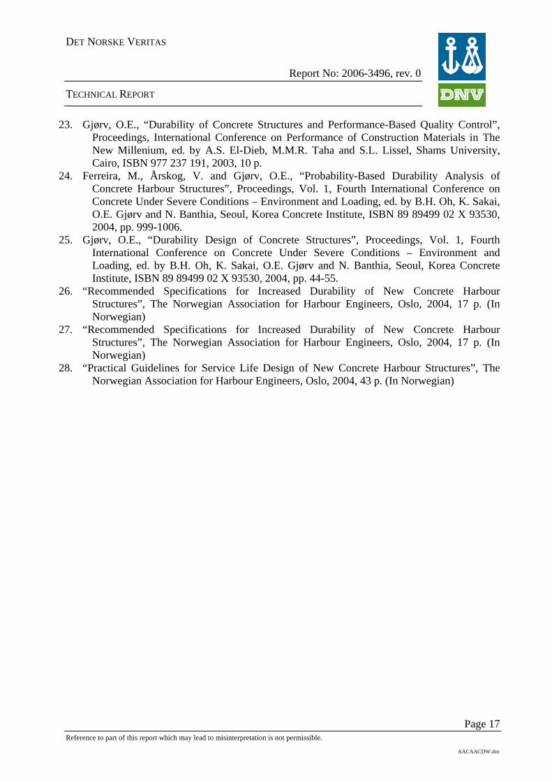
However, for several of the structures, a certain amount of steel corrosion has already been observed and minor repairs carried out. The above results indicate that the chlorides may penetrate the specified concrete cover in the splash zone within a service period of 25-30 years. For the Brent C Platform (1975), where enough data was available to carry out a probability-based durability analysis, Figure 3.1.6 shows that a risk level of 10 % for steel corrosion is rapidly exceeded after a service period of approximately 20 years.
0102030405060708090
100
0 20 40 60 80 1
Time (years)
Ris
k fo
r dep
assi
vatio
n (%
00
)
Figure 3-1-6 Development of risk for steel corrosion in the Brent B Platform (1975) /20/.
In addition to the corrosion of embedded steel, the potential corrosion problem for all the freely exposed metallic components attached to the concrete structures has already been pointed out. For majority of the platforms, a relatively high anode consumption at an early stage of operation has been observed, but after some time, the rate of anode consumption has typically been reduced to a more stable value. Current experience with rates of anode consumption appears to vary from one location to another within the same structure and also from one structure to another /24/. Since different guidelines and recommended practice for cathodic protection of the structures have been used for the design of cathodic protection system, different design values for current drainage to the embedded steel were applied /24/. It is important, therefore, that the inspection schedule and procedure are relevant for a particular structure in order to ensure a close and systematic monitoring of the anode consumption rates.
3.1.4 State of the Art on R&D For all the concrete structures in the North Sea, the durability specifications were based on prescriptive requirements on the composition of concrete mixes and on execution of concrete work. In order to obtain a more controlled durability and service life of new concrete structures
Page 14 Reference to part of this report which may lead to misinterpretation is not permissible.
AACAACDW.doc

DET NORSKE VERITAS
Report No: 2006-3496, rev. 0
TECHNICAL REPORT
in marine environment, a rapid development of probability-based durability design has recently taken place /25/. Durability design based on these new principles has now become the basis for new recommendations and guidelines for increasing durability of Norwegian concrete harbour structures /26, 27/. These new design procedures include the following elements:
- Probability-based durability analysis - Evaluation of alternative strategies and protective measures - Documentation of obtained construction quality and durability - Preparation of a service manual for regular condition assessment and monitoring of
chloride penetration with protective measures for control of this penetration.
For the existing concrete structures in the North Sea, if regular observations on the rates of chloride penetration into the structures are made, the same probability-based procedures can also be applied for a more reliable extrapolation of the further chloride penetration and risk of steel corrosion.
3.1.5 Recommendations As several of the concrete structures in the North Sea are now approaching the intended service life of 25-30 years, current information indicates that an increasing amount of corrosion on embedded steel may be expected in the years to come. For increased service periods beyond what was originally specified, this may represent a future challenge to the operators. In order to better meet this challenge, a closer following up of the rates of chloride penetration in the splash zone of the structures is recommended. This following up should include regular measurements of chloride penetration in given critical locations of the shafts. Based on such measurements, numerical procedures for a probabilistic extrapolation of the further chloride penetration and a risk of embedded steel corrosion are available. More data on the chloride penetration into concrete is provided the more accurate and reliable such an extrapolation will be /24/.
In order to avoid unnecessary galvanic corrosion problems on the freely exposed metallic components attached to the concrete structures, a proper monitoring of the sacrificial anode systems for these components is of vital importance.
3.1.6 References
1. Gjørv, O.E., ”Durability of Reinforced Concrete Wharves in Norwegian Harbours”, Ingeniørforlaget AS, Oslo, 1968, 208 p.
2. Féderation Internationale de la Précontrainte (FIP), “Recommendations for the Design and Construction of Concrete Sea Structures”, London, 1973.
3. The Norwegian Petroleum Directorate, “Regulations for the Structural Design of Fixed Offshore Structures”, Stavanger, 1976.
4. Det Norske Veritas, “Rules for the Design, Construction and Inspection of Fixed Offshore Structures”, Oslo, 1976.
5. Gjørv, O.E., ”Performance and Serviceability of Concrete Structures in the Marine Environment”, Proceedings, Odd E. Gjørv Symposium on Concrete for Marine Structures, ed. by P.K. Mehta, CANMET/ACI, Ottawa, Canada, 1996, pp. 259-279.
Page 15 Reference to part of this report which may lead to misinterpretation is not permissible.
AACAACDW.doc

DET NORSKE VERITAS
Report No: 2006-3496, rev. 0
TECHNICAL REPORT
6. Gjørv, O.E., “Mechanisms of Steel Corrosion in Concrete Structures”, Proceedings, Vol. 2, EVALMAT 89, International Conference on Evaluation of Materials Performance in Severe Environments, Kobe, Japan, 1989, pp. 565-578.
7. Gjørv, O.E., Vennesland, Ø. and El-Busaidy, A.H.S., “Electrical Resistivity of Concrete in the Oceans”, Offshore Technology Conference, Houston, Texas, Paper No. 2803, 1977, pp. 581-588.
8. Gjørv, O.E., Vennesland, Ø. and El-Busaidy, A.H.S., ”Diffusion of Dissolved Oxygen through Concrete”, Materials Performance, Vol. 24, 1986, pp. 39-34.
9. Gjørv, O.E. and Kashino, N., “Durability of a 60 Year Old Reinforced Concrete Pier in Oslo Harbour”, Materials Performance, Vol. 25, 1986, No. 2, pp. 18-26.
10. Vennesland, Ø. and Gjørv, O.E., 1981, “Effect of Cracks in Submerged Concrete Sea Structures on Steel Corrosion”, Materials Performance, Vol. 20, 1981, pp. 49-51.
11. Espelid, B. and Nilsen, N., “A Field Study of the Corrosion Behavior on Dynamically Loaded Marine Concrete Structures”, ACI SP-109, ed. by V.M. Malhotra, 1988, pp. 85-104.
12. Gjørv, O.E., “Steel Corrosion in Offshore Concrete Platforms”, Proceedings of the Industrial Seminar “The Ocean – Our Future”, The Norwegian University of Technology, NTH, Trondheim, 1977, Tapir, Trondheim, 1977, pp. 390-399. (In Norwegian).
13. FIP Concrete Sea Structures Commission, “Durability of Concrete Structures in the North Sea”, 1994, State-of-the-Art-Report, London, 1994.
14. Fjeld, S. and Røland, B., “Experience from In-Service Inspection and Monitoring of 11 North Sea Structures“, Offshore Technology Conference, Paper No. 4358, Houston, USA, 1982, 9 p.
15. Hølaas, H., 1992, “Condition of the Concrete Structures at the Statfjord and Gullfaks Oil Fields”, Report OD 92/87, The Norwegian Petroleum Directorate, Stavanger, (In Norwegian).
16. Elf Petroleum Norge A.S, (Private communication in 1995). 17. Gjørv, O.E., “Durability and Service Life of Concrete Structures”, Proceedings, The First fib
Congress 2002, Session 8, V. 6, Japan Prestressed Concrete Engineering Association, Tokyo, 2002, pp. 1-16
18. Sandvik, M. and Wick, S.O., “Chloride Penetration into Concrete Platforms in the North Sea “, Proceedings, Workshop on Chloride Penetration into Concrete Structures, Division of Building Materials, Chalmers University of Technology, Gothenburg, ed. by L.-O. Nilsson, Gothenburg, 1993, 7 p.
19. Sandvik, M., Haug, A.K. and Erlien, O, “Chloride Permeability of High-Strength Concrete Platforms in the North Sea “, ACI SP-145, ed. V.M. Malhotra, Detroit, 1994, pp. 121-130.
20. Department of Structural Engineering, Norwegian University of Science and Technology, NTNU, Trondheim. (Unpublished results)
21. Østmoen, T., “Field Tests with Cathodic Protection on the Oseberg A Platform“, Ingeniørnytt, Vol. 34, No. 6, 1998, pp. 16-17. (In Norwegian)
22. Aarstein, R., Rindarøy, O.E., Liodden, O. and Jenssen, B.W., “Effect of Coatings on Chloride Penetration into Offshore Concrete Structures“, Proceedings, Second International Conference on Concrete under Severe Conditions – Environment and Loading, ed. by O.E. Gjørv, K. Sakai and N. Banthia, E & FN Spon, London, New York, ISBN 0 419 23850 6, 1998, pp. 921-929.
Page 16 Reference to part of this report which may lead to misinterpretation is not permissible.
AACAACDW.doc
DET NORSKE VERITAS
Report No: 2006-3496, rev. 0
TECHNICAL REPORT
23. Gjørv, O.E., “Durability of Concrete Structures and Performance-Based Quality Control”, Proceedings, International Conference on Performance of Construction Materials in The New Millenium, ed. by A.S. El-Dieb, M.M.R. Taha and S.L. Lissel, Shams University, Cairo, ISBN 977 237 191, 2003, 10 p.
24. Ferreira, M., Årskog, V. and Gjørv, O.E., “Probability-Based Durability Analysis of Concrete Harbour Structures”, Proceedings, Vol. 1, Fourth International Conference on Concrete Under Severe Conditions – Environment and Loading, ed. by B.H. Oh, K. Sakai, O.E. Gjørv and N. Banthia, Seoul, Korea Concrete Institute, ISBN 89 89499 02 X 93530, 2004, pp. 999-1006.
25. Gjørv, O.E., “Durability Design of Concrete Structures”, Proceedings, Vol. 1, Fourth International Conference on Concrete Under Severe Conditions – Environment and Loading, ed. by B.H. Oh, K. Sakai, O.E. Gjørv and N. Banthia, Seoul, Korea Concrete Institute, ISBN 89 89499 02 X 93530, 2004, pp. 44-55.
26. “Recommended Specifications for Increased Durability of New Concrete Harbour Structures”, The Norwegian Association for Harbour Engineers, Oslo, 2004, 17 p. (In Norwegian)
27. “Recommended Specifications for Increased Durability of New Concrete Harbour Structures”, The Norwegian Association for Harbour Engineers, Oslo, 2004, 17 p. (In Norwegian)
28. “Practical Guidelines for Service Life Design of New Concrete Harbour Structures”, The Norwegian Association for Harbour Engineers, Oslo, 2004, 43 p. (In Norwegian)
Page 17 Reference to part of this report which may lead to misinterpretation is not permissible.
AACAACDW.doc
DET NORSKE VERITAS
Report No: 2006-3496, rev. 0
TECHNICAL REPORT
3.2 Steel 3.2.1 Introduction DNV has been involved in classification of offshore units, mainly Column Stabilised Units and Jack-ups since the 70’ties and 80’ties, and in the last two decades also ship-shaped units (FPSO’s and drilling vessels). Through this classification activity DNV has gained a wide experience related to degradation mechanisms for floating structures built in steel.
Normal design life for classed units is 20 years. The units built in the early 70’ties have now reached an age of approx. 30 years, which is significantly more than they were originally designed for. Therefore, during the last 5-10 years an increase focus has been made to degradation mechanisms relevant for these types of units, and how they can be dealt with in particular for units exceeding the original design life.
3.2.1.1 Main principles of classification The effect of degradation mechanisms on the safety level of floating structures is closely linked to the principles and survey scheme of classification. Classification is based on a renewal of the class certificate every 5th year, see /1/. This renewal includes a detailed survey, which includes general visual inspection, close visual inspection in way of expected critical details, and non-destructive testing (NDT) according to a pre-defined In-Service Inspection Programme (IIP) prepared by the classification society (DNV). The IIP is updated if experience for similar units indicates problem areas not known and not covered by the IIP.
In addition to the major renewal survey every 5th year, an annual survey is also carried out each year, and intermediate survey in the middle of a 5 year period to maintain the validity of the class certificate.
All together the classification survey scheme has proven to be a good tool to control the most common degradation mechanisms for floating units made of steel. The relevant degradation mechanisms are discussed in more detail below.
3.2.2 History There have been relatively few major accidents due to degradation of floating units. The most severe accident is Alexander Kielland (1980), which lost one column due to fatigue cracking. The crack started from welded detail in way of a hydrophone (Figure 3-2-1 and Figure 3-2-2). At that time the braces were normally filled with water, which made it impossible to detect any leakage due to the fatigue cracking, and the crack could grow to a critical size, with the following rapture of the brace element.
Other minor incidents have occurred, but in general it is fair to say that the degradation of the units have been monitored and controlled through the inspection programs, and necessary action such as maintenance and repair has been carried out to maintain the overall safety of the units avoiding major accidents.
Page 18 Reference to part of this report which may lead to misinterpretation is not permissible.
AACAACDW.doc

DET NORSKE VERITAS
Report No: 2006-3496, rev. 0
TECHNICAL REPORT
Figure 3-2-1 Alexander L. Kielland – loss of column (Source: The Alexander Kielland Accident. NOU 1981:11) /2/.
Figure 3-2-2 Alexander L. Kielland – position of crack (Source: The Alexander Kielland Accident. NOU 1981:11) /2/.
Page 19 Reference to part of this report which may lead to misinterpretation is not permissible.
AACAACDW.doc

DET NORSKE VERITAS
Report No: 2006-3496, rev. 0
TECHNICAL REPORT
3.2.3 Main degradation mechanisms There are two main degradation mechanisms relevant for the overall integrity of an offshore steel structure:
- Corrosion: uniform/pitting (see Section 2.1.2.3, O2-corrosion)
- Fatigue (see Section 2.1.3)
3.2.3.1 Corrosion In general corrosion is a visual degradation mechanism which can be monitored by scheduled inspection e.g. as specified by the classification scheme. Experience from 35 years with classification of floating offshore units is that corrosion is mainly a mechanism which causes local structural damage, but no major reduction in the overall safety level of the units as long as proper inspection schemes and maintenance is provided.
Already from the early 70’ties when the classification activity started, DNV had relatively strict requirements to corrosion protection. DNV introduced specific requirement to the quality of the corrosion protection arrangement. Most common is coating and sacrificial anodes, and to some extent impressed current. Most ship-shaped units are also built with thickness allowance to account for corrosion. Column-stabilised units and jack-ups are normally not built with thickness allowance, since coating is required in all corrosion critical areas.
3.2.3.2 Present situation – Ageing rigs Due to the Owner’s maintenance schemes and also the Rule requirements applied already from the 70’ties, most floating units following these Rules are in general in good condition. The main problem areas have been internal tanks used for trimming of the unit. Such tanks will have a frequency of filling/emptying, which gives good conditions for corrosion (Figure 3-2-3 and Figure 3-2-4). Such areas are given special focus in the class inspections. In general corrosion is not found to be a safety critical degradation mechanism provided a classification in-service inspection programme is followed and proper actions are taken based on the findings. At each renewal survey DNV checks that the rig has an acceptable condition for 5 new years in operation. The acceptance criteria are the same for new and old units and therefore the age of the unit is not important as long as necessary inspection and maintenance is carried out, see /1/.
Page 20 Reference to part of this report which may lead to misinterpretation is not permissible.
AACAACDW.doc

DET NORSKE VERITAS
Report No: 2006-3496, rev. 0
TECHNICAL REPORT
Figure 3-2-3 General Corrosion inside ballast tank (DNV photo).
Figure 3-2-4 Heavy Corrosion inside aft peak ballast tank.
Page 21 Reference to part of this report which may lead to misinterpretation is not permissible.
AACAACDW.doc

DET NORSKE VERITAS
Report No: 2006-3496, rev. 0
TECHNICAL REPORT
3.2.3.3 Fatigue Fatigue (Section 2.1.3) has been the most important and most focused degradation mechanism for floating offshore structures. There are several challenges related to fatigue as a degradation mechanism and as a design parameter for ageing rigs.
Analysis Methodology Floating units built 20-30 years ago were designed based on the methodology and design requirement valid at that time. Limited experience was available, and software and computer capacity limited the possibility to carry out detailed analysis for critical areas. Today the computer capacities allow more detailed fatigue analysis to be carried out. Such analysis together with experience (crack history) from operation of these units the last 20-30 years have revealed that the fatigue life was over-estimated for some parts of the units. This means that some details, normally local hot-spots in way of bracket toes etc., have fatigue life less than the required design life when re-calculated according the present methodology.
Load history Floating mobile units are normally designed to operate world-wide based on the scatter diagram for the North Atlantic, assuming an equal distribution of the wave direction. The approach assumes that the unit is moved around with dominating waves from all direction. In reality some units may stay on one location for a long period with one dominating wave direction. This may cause increased fatigue damage in some areas, while other areas are less loaded.
Fabrication The fabrication quality of fatigue critical details is of vital importance for the fatigue capacity. Local workmanship and compliance with design drawings are both important. The design calculations are based on a defined quality of the workmanship and also based on structural details as given on design drawings. Poor workmanship (e.g. substandard welding) or wrong details (e.g. details not built in accordance with design drawings) may reduce the actual fatigue capacity significantly. The crack causing the Alexander L. Kielland accident starts from a detail in way of the hydrophone which was not shown on the design drawing.
Rule development
After the Alexander L. Kielland accident the rule requirements were changed. The main changes related to fatigue and consequences of fatigue were as follows:
- all braces (referred to as slender members) shall be watertight and redundant - water leakage detection to be installed in all braces to detect water leakage due to fatigue
cracking in an early stage - additional damage stability requirement
These new requirement focused on the rigs possibility to survive after an accident / damage, and also to detect a crack propagation as early as possible. Early detection gives time to plan an implement repairs or other compensating measures. Present situation - Ageing rigs DNV has introduced a Fatigue Utilisation Index (FUI) as a parameter to measure the “used” fatigue life. The parameter takes into account the number of years in operation and where it has operated.
Page 22 Reference to part of this report which may lead to misinterpretation is not permissible.
AACAACDW.doc

DET NORSKE VERITAS
Report No: 2006-3496, rev. 0
TECHNICAL REPORT
life fatigueDesign life fatigue Used
=FUI
More detailed definition is given in DNV-OSS-101, Ch.3 Sec. 1, I100.
Many floating units have reached their documented fatigue life (FUI>1) and are still in operation. Some years ago DNV and the PSA started to focus on this situation, and DNV introduced some additional Rule requirement for units exceeding the documented fatigue life. These requirements are described in the DNV-OSS-101, Ch.3 Sec. 1 I. The content of this new requirements are as follows:
When a floating offshore unit reach its documented fatigue life one of the following options can be selected:
1. Units with no fatigue cracks during the first 20-30 years of operation can continue to follow the existing inspection schedule. Risk-based inspection methods show that unit with no cracks maintain the safety level also after exceeding the document fatigue life as long as no cracks are detected, see Figure 3-2-5. The methodology is described in OTC 11950 (2000): “Fatigue Reliability of Old Semi-submersibles”, /3/.
Fatigue life = 20 years
1,0E-04
1,0E-03
1,0E-02
1,0E-01
1,0E+00
0 5 10 15 20 25 30
time (years)
Failu
re p
roba
bilit
y
No Inspection
MPI every 5 year
Figure 3-2-5 Failure probability.
2. For units with fatigue cracks during first 20-30 years of operation one of the following steps should be taken, as decided by the Owner of the unit:
Owner shall assess structural details in fatigue critical areas with the purpose of improving the fatigue properties of the structure. The improvement may include, grinding, replacement of steel, modification of details, implementation of risk-based
Page 23 Reference to part of this report which may lead to misinterpretation is not permissible.
AACAACDW.doc

DET NORSKE VERITAS
Report No: 2006-3496, rev. 0
TECHNICAL REPORT
inspection methods considering the detailed information available for each detail, or a combination of these actions. Inspection programmes will be updated to reflect the outcome of these investigations
or
The NDT requirements similar to the extent for renewal survey are carried out on the intermediate survey. This means that the interval between the main NDT inspections is 2.5 years instead of 5 years. This is in line with results found from Risk-base Inspection methods, assuming that most of these units have had some fatigue cracks within the first 20 years of operation.
Similar requirement have been made for column-stabilised units and jack-ups.
The following inspection methods are involved for classed units in operation:
- visual inspection - overall inspection
- close visual inspection – inspection of pre-defined details expected to be critical
- Non-Destructive Testing (NDT)
o Magnetic Particle Inspection (MPI)
o Ultrasonic Inspection (UT)
o Eddy Current (EC)
Scope and extent of inspection and NDT is given in the In-Service Inspection Programs prepared for each unit classed by DNV.
3.3 References /1/ Rules for Classification of Offshore Drilling and Support Units, DNV-OSS-101,
October 2003.
/2/ The Alexander Kielland Accident. NOU 1981:11.
/3/ Fatigue Reliability of Old Semisubmersibles, OTC11950, G. Sigurdsson, I. Lotsberg, T. Myhre and K. Orbeck-Nilssen, Det Norske Veritas, 2000
Page 24 Reference to part of this report which may lead to misinterpretation is not permissible.
AACAACDW.doc

DET NORSKE VERITAS
Report No: 2006-3496, rev. 0
TECHNICAL REPORT
4 SUBSEA PIPELINES
4.1 Introduction As pipelines become older, the pipeline operators have several new challenges to consider, such as
– Changes in integrity, e.g. time dependent degradation mechanisms such as corrosion and fatigue (Section 2), or random mechanical damages (e.g. third party damages).
– Changes in infrastructure from the as built, e.g. increased fishing activity or heavier trawler gear.
– Changes in operational conditions, either as a natural change in well-stream condition, tie-in to other pipeline system or increased production rates.
– Required to operate beyond the design lifetime. – Design no longer valid due to the above mentioned issues.
4.2 History Generally, review and analysis of historically causes of pipeline failures worldwide /1, 2, 3/, indicate that corrosion, specifically internal corrosion, is the most widely reported cause of failure for offshore pipelines, followed by maritime activities (e.g. anchor- or trawling- damage and vessel collisions, so called third party damage (TPD)) and then natural forces (e.g. storms and mudslides).
In the PARLOC 2001-report /1/, which includes a total number of 542 reported pipeline/riser incidents in the North Sea (at the end of 2000), it is emphasised that there is a general opinion that the incident frequencies are highest in the early years of a pipeline’s life and towards the end of its life. The former has been attributed to higher vessel activity during the first years of field development and/or early appearance of flaws related to design, material, corrosion inhibition system etc. The latter is more related to changes in infrastructure from the as built, e.g. increased fishing activity or heavier trawler gear and corrosion of the system over time.
In the North Sea, the oldest pipeline is the 36” Ekofisk-Teeside oil export pipeline followed by the 36” Ekofisk-Emden gas export pipeline which came on stream in October 1975 and September 1977, respectively. Both pipelines are made of normalised CMn-steel API 5L X60 (similar to SMYS 415). One of the challenges related to the future operation of the Emden pipeline has been that the pipeline was designed and installed prior to the first issue of the NACE MR-0175. Since the H2S content is forecasted to increase in the future, and with that the risk for sulphide stress cracking (Section 2.1.2.3) if water is present, it has been of great importance to establish whether the pipeline material is suitable for a gradual “transition” to “sour service” condition or not.
Further, both pipelines are coated with an asphalt enamel coating but without reinforcement, which was not common before in the early 80’ies. These old type of coating has shown tendencies to spall with age. The same problem is not reported for pipelines covered with asphalt
Page 25 Reference to part of this report which may lead to misinterpretation is not permissible.
AACAACDW.doc
DET NORSKE VERITAS
Report No: 2006-3496, rev. 0
TECHNICAL REPORT
enamel including reinforcement or for polypropylene coating (PP). The PARLOC 2001 report does not contain any information about coating types and type of coating damages. The most commonly used materials for pipeline in the North Sea have been the carbon steel material grades X46, X52, X60 /3/. Later on more high strength steel as X65 and X70, and corrosion resistant steel as duplex/super duplex- and 13%Cr stainless steels, have been utilised as linepipe material. It has also during the last few years been installed quite a few CMn steel pipelines internally lined (mechanical bonding) or clad (metallurgical bonding) with CRA (e.g. AISI 316L, Incoloy 825 and Inconel 625).
4.3 Main degradation mechanisms Threats to the pipeline system shall be systematically identified, assessed and documented throughout the operational lifetime.
This shall be done for each section along the pipeline. Examples of typical threats are: • corrosion (internal/external) • third party damage (TPD) • erosion • development of free spans causing fatigue • buckling
As a result of the natural aging of a pipeline, corrosion and third party damages are considered to constitute the most relevant threats to the system.
Internal Corrosion is the most widely reported cause of failure for subsea pipelines (see Section 4.2). The internal corrosion includes a large variety of corrosion degradation mechanisms depending on the process medium, the material, the process condition etc. Internal corrosion in oil and gas pipelines is principally associated with CMn-steel and the following corrosion mechanisms (Section 2.1.2.3) are of main concern;
- H2S-cracking (SSC)
- CO2-corrosion
- Microbiologically Influence Corrosion (MIC)
Liquid water is prerequisite for any electrochemical reaction causing corrosion to occur. Internal corrosion is controlled by material selection (including clad pipe), applying a corrosion allowance (CA) on the inner surface of the CMn-steel pipe or by chemical treatment of the process fluid (e.g. corrosion inhibitor, pH-stabilisation).
External corrosion is controlled by the use of an external corrosion coating in combination with a cathodic protection (CP) system in case of coating damages (Section 2.1.2.2). The control of external corrosion will therefore depend on the type and quality of the external coating and the design of the CP-system.
• External coating; Corrosion protection often consists of a tight protective layer around the pipeline exterior. The external protective coating is often asphalt enamel or fusion
Page 26 Reference to part of this report which may lead to misinterpretation is not permissible.
AACAACDW.doc

DET NORSKE VERITAS
Report No: 2006-3496, rev. 0
TECHNICAL REPORT
bonded epoxy (FBE) covered with other types of plastics, as polyethylene or polypropylene, for mechanical protection or as heat insulation. Asphalt can only be utilised together with concrete coating (e.g. weight coating).
• Concrete weight coating; Concrete is applied to the coated pipeline to provide the required compaction and density. The thickness of the concrete ensures both mechanical protection and density for negative buoyancy. Concrete weight coating systems provide the following advantages; sub-sea stability, prevention of damage by e.g. ship's anchors, no trenching and less steel is required.
With the exception of the coating systems used on the oldest pipelines in the North Sea (Section 4.2), no coating damages related to “natural aging” of the coating itself have been reported /4/. The field joint coating (FJC), which are specifically high risk areas for increased bacterial activity and a subsequent increase in the external corrosion, has been a topic for debate. To DNV’s knowledge, no incidents have been reported where significant wall thickness loss has been detected.
The quality and properties of modern coatings and the quality control associated with the manufacturing of coating have been considerably improved over the last years. Recommendations for the process of applying specific types of FJC/coating field repair (CFR) and 'infill' systems, and for the process of applying external coating systems for corrosion control of submarine pipelines at the coating plant are, as an example, given in DNV-RP-F102 /5/ and DNV-RP-F106 /6/, respectively. As a consequence of the quality improvement, a considerably less conservative CP-design is necessary compared with recommendations in older CP-design codes (i.e. with respect to coating breakdown factors and hence the net galvanic anode mass to be installed). This is reflected in the newer CP-design codes, DNV RP-F103 (2002) and ISO 15589-2 (2004) /7, 8/.
Most experienced coating damages are related to external impact (TPD). The risk for third party damage (i.e. mechanical damage of the pipeline) is an issue during the entire life of the pipeline, however, as mentioned in Section 4.2, the incident frequencies are highest in the early years of a pipeline’s life and towards the end of is life.
All subsea systems (e.g. structures, pipelines, platforms) shall principally be provided with its own CP-system. Interaction in terms of current drain between the pipeline CP system and adjacent subsea installations electrically connected to e.g. platforms or crossing pipelines may cause excessive anode consumption of one of the structures. As the utmost consequence a reduced design life of the CP-system and thereby an under-protection of the pipeline system may occur.
4.4 Failure modes The main failure modes for pipelines are normally considered to be;
• Leakage
• Burst
• Local Buckling / Collapse
Page 27
Leakage in pipelines is often associated with the presence of local corrosion attacks (e.g. local CO2-corrosion, pitting), but might also be a result of small cracks. Burst is more associated with
Reference to part of this report which may lead to misinterpretation is not permissible.
AACAACDW.doc

DET NORSKE VERITAS
Report No: 2006-3496, rev. 0
TECHNICAL REPORT
a uniform wall thickness reduction or more extensive crack propagation, decreasing the pressure capacity of the pipeline. Local buckling is a failure mode confined to a short length of the pipe causing gross changes of the cross section; collapse. For subsea pipelines, this is often related to external overpressure in combination with a wall thickness reduction (e.g. as a result of corrosion).
4.5 Ensuring integrity of subsea pipelines For a given design, corrosion monitoring, corrosion mitigating measures and inspection of the system are fundamental activities to control the integrity of a pipeline system during its design life. As illustrated in Figure 4-1, several activities are necessary to be able to control the integrity of the pipeline system.
To be able to perform an integrity assessment of a pipeline system, the data and results from the activities illustrated in the figure has to be made available. One of the challenges with older pipeline system is that historical data and also often original design, fabrication and installation data and reports are lacking. This complicates the possibility of performing a reliable integrity assessment.
Figure 4-1 Activities necessary to control the integrity of the pipeline system.
Condition Monitoring
Process-, Product-Control
Corrosion Monitor.
External Inspection
Internal Inspection
Process Data
Product Analyses
Chemical Injection
Pipeline Segment
Integrity Assessment
Corrosion Assessment
Mechanical Assessment
Pipeline Condition
Repair / Modification
Page 28 Reference to part of this report which may lead to misinterpretation is not permissible.
AACAACDW.doc

DET NORSKE VERITAS
Report No: 2006-3496, rev. 0
TECHNICAL REPORT
A short description of the main activities that constitute the pipeline integrity management system is given below. More detailed requirements to managing system integrity are given in industry standards as API 1160, ASMEB31.8S and DNV-OS-F101 /9, 10, 11/.
4.5.1 Process- and product control Process- and product-control includes the following;
• Process control (pressure, temperature, flow rate etc) • Product sampling (CO2, H2S, O2, water cut/dew point, sand etc) • Chemical injection for corrosion prevention (corrosion inhibitors, pH-stabilisation
etc.) The process- and product control shall ensure that the condition in the pipeline is within the operational window as defined in design. If e.g. a souring of the well stream occurs, increasing the H2S-content and with that exceeding the maximum specified limit as given in design, this information should be handed over to the responsible for pipeline integrity. For gas lines, the dew point should be monitored and for liquid lines, the water cut should be known. Further, for chemical injection, the availability (or efficiency) given in design should be known together with the precautions taken to ensure the chosen availability. As an example, a 95% inhibitor availability requires, according to NORSOK M-001, that a qualified inhibitor is injected from day one and that a corrosion management system is in place to actively monitor corrosion and inhibitor injection. Any redundancy in the system should be elucidated ensuring e.g. continuous injection of corrosion inhibitors even though one pump fails and thereby maintaining the required availability.
4.5.2 Corrosion Monitoring The rate of corrosion dictates how long any process equipment can be safely operated. When applying corrosion monitoring techniques it is vital that the equipment is installed in locations where corrosion might occur (e.g. lowest points where liquid might accumulate in confined areas). Otherwise, the data received from such measurements will have no relevance when assessing the integrity of the system.
Typical corrosion monitoring techniques are; • Corrosion coupons / ER-probes / LPR probes • Sampling • Field Signature Method - corrosion monitoring • DDL - Deposition Data Logger • UT of fixed spots • Sand/Erosion
Off the techniques listed above, corrosion coupons, ER- and LPR-probes together with sampling form the core of industrial monitoring systems. The other techniques are normally found in specialised applications. However, it should be emphasised that corrosion coupons and probes are not suitable for documenting the prospective corrosion in a pipeline but to monitor any changes in the fluid corrosivity.
Page 29 Reference to part of this report which may lead to misinterpretation is not permissible.
AACAACDW.doc

DET NORSKE VERITAS
Report No: 2006-3496, rev. 0
TECHNICAL REPORT
4.5.3 External Inspections Typical external inspection methods are;
• Visual Inspection (GVI/CVI) performed by divers • Inspection performed by using Remote Operated Vehicles (ROV); Video, Sonar,
Transponders, Profilers, etc. • External Ultrasonic Testing and Thickness Measurement for verification of metal loss
or cracks During such inspections the following is typically inspected:
• The CP system - looking for excessive consumption of the anode mass. • Indication of inadequate coverage of buried or rock dumped pipeline sections • Visual inspection of anode consumption • Recording of anode potential and steel potential if practically • Field gradients at anodes • Coating or concrete damages • General damage to pipelines from impact (dropped object, equipment handling,
anchor impact or dragging, fishing, etc.) • Flanges and hubs – looking for leaks • Looking for upheaval buckling or snaking
For buried pipelines, as-laid surveys along the entire length of the pipeline have to be performed prior to backfilling (buried). Significant damages to the coating and sacrificial anodes shall be recorded and the consequences for long-term performance considered. When the pipelines are buried, no further inspections of the coating or anodes are possible.
4.5.4 Internal Inspection In-line inspections (ILI) are normally performed to verify the internal surface condition of the pipeline system but are also, depending on the chosen tool, capable of verifying the external condition with respect to corrosion and cracking.
Several types of tools for internal inspection, cleaning and batching are available on the market. An overview of types of tools associated with in-line inspection (ILI) and cleaning/batching of pipeline-systems is given in Figure 4-1.
Additionally, ILI might be performed to monitor the efficiency of the corrosion protection (e.g. external coating) and the prevention systems (i.e. corrosion inhibitor, dew-point, water cut etc). ILI is the only method that brings high confidence with respect to e.g. inhibitor availability (and efficiency) by verifying the actual condition of the pipeline internal surface.
Page 30 Reference to part of this report which may lead to misinterpretation is not permissible.
AACAACDW.doc

DET NORSKE VERITAS
Report No: 2006-3496, rev. 0
TECHNICAL REPORT
Types of Tools
Free Swimming
Cabele Operated
Tools
Cleaning and Batching
ToolsTools
In-Line Inspection
Tools
Pumped Tools
Crawler Tools
Cleaning Pigs
Batching Pigs
PU-Pigs 1)Geometry Tools
Metal Loss Tools
Metal Loss Tools
Batching Pigs
Bi-Di Pigs 2)Mapping Tools
Crack Tools In-Line Coating
Crack Tools
Metal Loss Tools
Speciality Pigs
Video Pigs
Page 31
Figure 4-1 Overview of different types of internal inspection and cleaning/batching tools (source: NDT Systems & Services AG).
1) PU-pigs; Polyurethane Pigs Crack Tools 2) Bi-Di pigs; Bidirectional Pigs
Leak Detection
Tools
4.5.5 Hydrostatic pressure testing Pressure testing is an industry-accepted method for validating the integrity of the pipeline. The pipeline is tested up to a load of approximately 1.1 x operating pressure to 95% SMYS. The pressure test is normally performed as a combined strength and leak test. Upon completion of pressure testing, the pipeline should be properly cleaned, de-watered and dried to avoid future corrosion in the system. Experience shows that local corrosion in pipeline systems is often attributed to water leftover from the pressure test.
4.6 “Corrosion Zones” associated with external corrosion. External surfaces of subsea pipeline systems may be divided into “corrosion zones”, based on the environmental parameters that determine the actual corrosivity. The physical characteristics of the corrosion zones further determine the applicable techniques for corrosion monitoring and inspection.
The following major zones may apply;
Reference to part of this report which may lead to misinterpretation is not permissible.
AACAACDW.doc

DET NORSKE VERITAS
Report No: 2006-3496, rev. 0
TECHNICAL REPORT
Atmospheric Zone (Offshore): For pipelines on an exporting platform and on riser platforms, a “marine atmospheric zone” will apply from the pig launcher and to the upper limit of the riser’s splash zone. The unmitigated corrosion rate of carbon steel in a marine atmospheric zone is in the range 0.1 to 0.3 mm/yr at ambient temperature but may become significantly higher (0.3-1 mm/yr) for hot surfaces directly exposed to sea spray. In areas sheltered from sea spray, the unmitigated corrosion rate will approach the lower limit of the range (i.e. 0.1 mm/yr).
Closed compartments with humidity control are referred to as a “dry atmospheric zone”.
Corrosion protection means: Coating and corrosion allowance (CA)
Inspection method: Visual inspection and in-line inspection (pigging)
Marine Splash Zone (Offshore): The marine splash zone can be defined as the area of e.g. a riser that is periodically in and out of the water by the influence of waves and tides. The actual length of the “splash zone” varies based on the actual geographical location and, moreover, from one splash zone definition to another. Extremely corrosive conditions may prevail for hot risers just above the water level; 3-10 mm/yr has been reported for risers with a wall temperature of about 100 oC. In the splash zone below the water level, the unmitigated corrosion rate is close to that in the seawater submerged zone (see below).
Corrosion protection means: Upper zone: Coating and corrosion allowance (CA)
Lower zone: : Coating, corrosion allowance (CA) and CP-system
Inspection method: Upper zone: Visual inspection and in-line inspection (pigging)
Lower zone: Visual inspection, in-line inspection (pigging) and CP-monitoring
Seawater Submerged Zone; The corrosivity of the seawater submerged zone is relatively low and unmitigated carbon-steel corrosion rates in excess of 0.1 mm/yr would only be expected for surfaces heated by an internal fluid. For ambient temperature surfaces, the unmitigated corrosion rate is below 0.1 mm/yr, although slightly higher values may apply for local pitting attacks.
Corrosion protection means: Coating, and CP-system
Inspection method: In-line inspection (pigging) and CP-monitoring
Page 32 Reference to part of this report which may lead to misinterpretation is not permissible.
AACAACDW.doc

DET NORSKE VERITAS
Report No: 2006-3496, rev. 0
TECHNICAL REPORT
Offshore Buried Zone; In general, the corrosion rate in marine sediments is very low (<< 0.1 mm/yr) but high local corrosion rates (of the order of 1 mm/yr) may apply in the uppermost sediments if the bacterial activity is high. Internal heating of the pipe surface to 20 to 50 oC increases bacterial activity and hence the potential for microbiologically induced corrosion. (at higher temperatures, bacterial corrosion is inhibited). Pipeline sections covered by rock dumping, gravel and by other means are normally defined as “buried”.
Corrosion protection means: Coating, and CP-system
Inspection method: In-line inspection (pigging)
4.7 Technology Status The available technology for monitoring and inspection of pipelines have increased compared to the 70’ies and pipelines that were previously difficult or even impossible to inspect, may now be accessible. The accuracy of equipment (as MFL, UT, product measuring devises etc) has also been improved over the last years which brings a higher degree of confidence on the monitored data and, with that, a more reliable assessment of the pipeline condition (i.e. integrity assessment). An accuracy of ±10% (at 80% confidence) and ±0.5 mm (at 90% confidence) is typically reported for MFL and UT pigs, respectively.
The definition of “un-piggable” lines is given as lines that are not designed for allowing standard inspection tools to pass through, which basically requires a more or less constant bore, sufficient long radius bends and traps to launch and received pigs. Today, the inspection equipment can be tailor-made in order to overcome the situation that was previously considered “un-piggable” with respect to standard tools.
Further, since some incidents in the past can be related to lack of industry experience (as for the 13Cr stainless steel, HISC incidents associated primarily with the CP-system), the increased experience following such events will normally decrease the likelihood for similar events to occur again.
Advanced pipeline repair and rehabilitations products and services (covering steel, plastics and epoxy composite), as the Pipeline Repair System (PRS) /12/, have been developed, together with more sophisticated and robust programs for analysis and assessment of pipeline condition, allowing repair and further use of damaged pipelines.
More detailed requirements to managing system integrity are given in industry standards as API 1160, ASMEB31.8S and DNV-OS-F101.
Page 33 Reference to part of this report which may lead to misinterpretation is not permissible.
AACAACDW.doc

DET NORSKE VERITAS
Report No: 2006-3496, rev. 0
TECHNICAL REPORT
4.8 References /1/ PARLOC 2001 “The update of loss of containment data for offshore pipelines”,
M.MacDonald Ltd for The Health and Safety Executive, The UK Offshore Operators Association and the Institute of Petroleum, July 2003
/2/ “Improving the Safety of Marine Pipelines”, Committee on the Safety of Marine Pipelines (USA), 1994
/3/ “Pipeline damages – Damages and Incidents from Petroleum Safety Authority’s CODAM database”, PSA Norway, August 2006
/4/ “Nedbryting av rørledninger over tid”, Rev.02, Det Kongelige Olje- og Energidepartement, 03.09.1998
/5/ DNV RP-F102 “Pipeline Field Joint Coating and Field Repair of Linepipe Coating”, October 2003
/6/ DNV RP-F106 “Factory Applied External Pipeline Coatings for Corrosion Control”, October 2003
/7/ DNV RP-F103 ”Cathodic Protection of Submarine Pipelines by Galvanic Anodes”, October 2003
/8/ ISO 15589-2 ”Petroleum and Natural Gas Industries – Cathodic Protection of Pipeline Transportation Systems; Part 2; Offshore Pipelines”, 2004
/9/ API Standard 1160, “Managing System Integrity for Hazardous Liquid Pipelines”, 2001
/10/ ASME B31.8S, “Managing System Integrity of Gas Pipelines”, 2001
/11/ DNV OS-F101, “Submarine Pipeline System”, 2000
/12/ DNV report No.2005-3394 “Joining Methods-Technology Summaries”, Rev.01, 12.10.2005
Page 34 Reference to part of this report which may lead to misinterpretation is not permissible.
AACAACDW.doc
DET NORSKE VERITAS
Report No: 2006-3496, rev. 0
TECHNICAL REPORT
5 SUBSEA EQUIPMENT
5.1 Introduction Subsea equipment will in this section be template, manifold and subsea Christmas tree (XT) system. The Subsea wellhead system is covered in Section 6, Drilling and wells.
5.2 Template Templates are normally manufactured of low alloy carbon steel and protected against corrosion by a CP system. For the Norwegian continental shelf, the templates are integrated units with manifold and external fishing gear protection for protection of wellhead systems and the manifold. The template is exposed to forces that develop between the wellhead foundation, wellhead thermal growth/well temperature extension and pipeline forces. The template is also seeing the gravity forces from the manifold, which the template serves as foundation for. Forces generated from wellhead growth and pipeline can over the time of operation be changing, but definitely not in a number of cycles that causes fatigue to be a problem. However, forces experienced from trawl gear might have severe effect of the function to template structure. Due to continuous development of fishing gear, both with respect to shape and mass, can effect of those be outside original design criteria of the template. Detail to template design such as handles, hatches, indicators etc. can be a potential snag point leading to sudden impact loads that might give local defects.
5.2.1 Workmanship The templates are welded structures, normally manufactured in low alloy carbon steel. The template is being exposed to a set of different load scenarios that might have the extreme load condition during transportation/installation compared to in service condition. The building quality of the template will depend on the quality of the steel, welds, coating, electrical continuity straps and, if depth dictates, punctured members. They are all falling in under quality assurance that can be part of manufacturing procedures and Factory Acceptance Test (FAT). The overall quality and ability to sustain any future condition of changed loads is up to what quality the template is designed for. The latter element, i.e. all future load conditions, might be hard to detect upfront.
5.2.2 Degradation mechanism The template, as a low alloy carbon steel structure shall be protected against corrosion through cathodic protection assisted with high quality coating. Normally epoxy based paint according to NORSOK is used. The template design also often includes anodes to protect wellhead and the current drainage through the well shall be accounted for in CP design. Failure mechanism with respect to corrosion would therefore be related to:
1) Lack of electric continuity to all protected parts.
2) Coating not intact leading to excessive anode consumption.
3) Inadequate anode design and/or quality; anodes may fall off after some time in operation etc.
Page 35 Reference to part of this report which may lead to misinterpretation is not permissible.
AACAACDW.doc

DET NORSKE VERITAS
Report No: 2006-3496, rev. 0
TECHNICAL REPORT
Degradation mechanism to the structural integrity to the template can be related to unfavourable effect of load combinations and operation outside original design criteria. This can be explained by change in foundation due to sea bed erosion, new tie-ins or subsequent rock dumping outside what original designed for. Severe global failure of a template structure would be by external applied forces which can be: BOP impact loads, conductor string installation or external forces created by impact with equipment from non oil and gas production equipment, such as anchors and fishing gear.
5.2.3 Inspection programme Inspection programme should typically cover following items:
• The CP system – looking for excessive consumption of anode mass and damaged/missing anodes.
• Recording of anode potential and steel if practically possible.
• Coating damages, both due to general degradation and as effect of contact with fishing gear.
• General damage to structure from fishing gear.
• Hatches, handles and other elements that serve a function or can generate a snag point.
• Inspect earth cabling used to ensure electrical continuity.
5.3 Manifold For the Norwegian sector of the North Sea the manifold is an integral part of the template and it can be a retrievable unit from the template. The manifolds today are often manufactured from prefabricated pipes and components in 22Cr duplex materials. According to pressure requirements and requirements to flexible pipe design elements can also be manufactured of 25Cr Super Duplex materials. The mechanical behaviour and mechanism of these materials are as described in Section 2.1.2.2 External corrosion (i.e. HISC). After incidents, both on the Norwegian continental shelf as other places, failure in components of this material have led to a number of activities in order to get an understanding of failure mechanism as well as developing design guidelines (DNV RP F-112 /2/) to avoid this failure in the future. Current recommendation of usage of 22Cr Duplex and 25Cr Super Duplex materials have today a more conservative approach with respect to allowable working stress level in the material. The design guidelines today includes routines and checks to allowable stress level that is not covered by former industry practice to pipe stress and component calculations.
5.3.1 Workmanship The manifold is a safety critical element and involves a number of mechanical components (valves, connectors, and sensors) that can fail. These components and the manifold piping itself are manufactured from advanced materials. The manifold piping are normally with welded connections and the valve bodies are welded in the manifold piping. Sensors tend to be bolted by approved flange styles. Welding is a critical process both with respect to onsite pressure testing as well as in service condition. Welds gives changes to material properties and residual stresses
Page 36 Reference to part of this report which may lead to misinterpretation is not permissible.
AACAACDW.doc

DET NORSKE VERITAS
Report No: 2006-3496, rev. 0
TECHNICAL REPORT
are inherently present at welds (post weld heat treatment will reduce the residual stresses, if carried out). Workmanship and control here is important both to welding qualification and non destructive testing, and the components should be designed to cater for latest development in design rules for HISC sensitive materials. The overall quality plans for manufacturing and testing must follow good practice, and testing shall be conducted according to the correct sequences. It is of importance that industry practice of pressure test of components and welds are done prior to coating. Piping insulation shall be according to verified and accepted procedures as well as being quality checked against these.
5.3.2 Degradation mechanism Degradation mechanism for the manifold can be summarized to material aspects as well as functional aspects. The manifold piping is manufactured of different materials with different corrosion resistance. Typical material selection can be Duplex (22Cr ferritic-austenitic steel), Super Duplex (25Cr ferritic-austenitic steel), 6Mo for process bore piping, whilst control system piping can be of the less noble 316 (austenitic steel).
With respect to the external environment, all piping will be subjected to CP, not only for its own protection, but also to protect other components as valves, actuators, connectors and instruments. Also the latter components can be of different materials, and should in general through engineering processes, be made of materials that have robustness to HISC.
If the process piping is insulated to reduce cooling effect from ambient seawater, the insulation material shall be sufficiently resistant to degradation when submerged in seawater. Degradation can be a combination of absorbed seawater, with elevated temperature due to hot produced fluids. Degradation of insulation can also be mechanical damage. This will be from operation and contact with foreign objects, or it can be due to deflection and strain absorbed by pipe material which causes the insulation material to crack. Due care shall be paid so unwanted effect of damage to coating in combination with reduced CP. This condition can lead to accelerated degradation to the metallic pipe material when seawater is exposed to bare material and the CP potential is not sufficient.
Valves, valve actuators and instruments are all components that will be manufactured from different materials, where major bodies and shells can be made from low alloy carbon steel. It is therefore of importance that these components are electrically connected so CP protection is ensured. When degradation is discussed, this will also involve moving components. Especially override mechanisms and sliding stems can loose some of its intended purpose due to effects of degradation to material, marine growth, and calcareous deposits. This can lead to increased friction and wear and subsequent leakages to sea from e.g. actuator housings.
Other components that are of importance are clamps and connectors. Careful design with suitable material selection should normally avoid potential problems.
With respect to the internal environment, internal corrosion and erosion are considered the most relevant failure mechanisms.
Page 37 Reference to part of this report which may lead to misinterpretation is not permissible.
AACAACDW.doc

DET NORSKE VERITAS
Report No: 2006-3496, rev. 0
TECHNICAL REPORT
5.3.3 Inspection programme Manifold inspection shall cover following checks:
• General condition to pipe coating • General condition to components, valves, actuators and instruments • Inspect for leakages at valves and components • Inspect all connector to trees and pipelines • Pressure test • Visual inspection to detect foreign objects
5.4 Subsea Christmas tree (XT) Subsea XT components are generally manufactured from low alloy carbon steel. Wetted surfaces to produced fluids are normally with corrosion resistant alloy (Inconel 625 etc). The tree itself is a construction with a number of pressure containing components bolted together with flange type connections. It is of importance that these components are assembled together after formalized procedures to safeguard quality. The externals of the tree are protected against corrosion by a CP system together with a coating, normally an epoxy based coating. It is of importance that the metallic material which is used is not exceeding strength and hardness requirements for the industry. Also, as mentioned, since the tree consists of several components bolted together it is of importance that all components are electrically connected to ensure cathodic protection. Internal corrosion is as mentioned in Section 2.1.2.3 and should within normal use not be of concern. However, the internals of the tree can be exposed to well stimulation chemicals, especially after interventions that can be of aggressive nature, even when exposed to the CRA. Some barriers may contain non metallic seals. It is reasonable to believe that all such seals could not be documented at time of design to actual working design life.
5.4.1 Workmanship The subsea XT are a critical safety barrier as well as it is probably the most advanced product that is permanently installed. The XTs are built of advanced components and there is a mixture of low alloy steel components as well as high alloy stainless steel materials. Common for both are that they are sensitive to thermal effects from welding so it is important that all heat treatment and welding activities are done after qualified and approved procedures. In contradiction to the manifold all components on a XT are connected by bolted connections, or by a flange type connection. Compared to a welded pressure container there is no formal certification of how to assemble a bolted connection. It is therefore of importance that a proper good bolt torque procedures exist and are understood by the personnel that is doing the job. The XT are during its FAT extensively tested, but long term effect to the assembly will not be discovered, either in qualification test or in FAT. I.e. there is a discussion in the industry to whether the tree is experiencing vibration. However, regardless of vibration or its potential frequency, it is important that slim members, such as small bore piping are supported sufficiently such that long term effect of vibration does not lead to breakage.
Page 38 Reference to part of this report which may lead to misinterpretation is not permissible.
AACAACDW.doc

DET NORSKE VERITAS
Report No: 2006-3496, rev. 0
TECHNICAL REPORT
5.4.2 Degradation mechanism Degradation of the tree is dependant to what it is subjected to in service. Normal service should be accounted for in detail design, both with respect to exposure to produced fluids, injection chemicals as well as external exposure to seawater with its parameters. Such parameters can be external temperature, location, and seawater depth. Degradation can also be divided into material degradation and functionality to components. For the tree, the major building blocks are made from low alloy carbon steel with relatively high strength. Those components are in most cases coated by an epoxy based coating. For some projects the sensitivity to flow assurance is based on strict requirement to temperature insulation. If this is the case the entire tree block should be insulated, and not only limited to the external process piping. Degradation of coating or insulation can lead to reduced availability in production. High temperature to epoxy coated surfaces can lead to excessive degradation of coating. This shall however be accounted for in the system CP design. For temperature insulation-material care shall be taken to seawater absorption, mechanical wear from impact of external components, and loss of binding between insulation and steel material. The latter can lead to severe local corrosion if the combination is unfavourable wrt seawater access and lack of CP effect. High strength material, both of carbon steel as well as sophisticated stainless qualities, shall be selected with sufficient margin to avoid HISC, and the operation stress level shall be below certain values. Valves, actuators, connectors and instruments are manufactured from a mixture of different metallic materials. The large shells and bodies are usually manufactured from low alloy carbon steel, and smaller components are likely to have some stainless type material, e.g. Duplex and Super Duplex. Override mechanisms and override stems that extend from actuator housing to external seawater atmosphere can be a potential degradation to functionality. E.g. marine growth, calcareous deposits can lead to failure of the sealing element between actuators and seawater allowing seawater into areas not tolerant to this. Also severe friction can, due to mentioned effects, lead to problems in operating e.g. valves or other mechanisms. The internals of the tree shall in normal service not be of concern. Through material selection the tree shall be robust. However, it seems to be situations were the well has been treated with chemicals than can have severe effect to tree internals when not flushed out satisfactory. These chemicals (which can be acid) can remain in dead end pockets, in seal grooves etc. and cause severe local damage. Effect to soft seals can be unknown.
5.4.3 Inspection program Inspection of Christmas tree shall cover following checks:
• The CP system – looking for excessive consumption of anode mass • Recording of anode potential and steel if practically • Coating damages, both due to general degradation and as effect of hot surfaces • General damage to structure from fishing gear • General condition to pipe coating • Inspect for leakages at valves, connectors, sensors and components • Pressure test • Visual inspection to detect foreign objects
Page 39 Reference to part of this report which may lead to misinterpretation is not permissible.
AACAACDW.doc

DET NORSKE VERITAS
Report No: 2006-3496, rev. 0
TECHNICAL REPORT
5.5 References /1/ DNV-RP-F112 Design of duplex stainless steel subsea equipment exposed to cathodic
protection, Draft issue April 2006
Page 40 Reference to part of this report which may lead to misinterpretation is not permissible.
AACAACDW.doc

DET NORSKE VERITAS
Report No: 2006-3496, rev. 0
TECHNICAL REPORT
6 DRILLING AND WELLS
6.1 Introduction As drilling equipment ages, the operator has several new challenges to consider, such as:
– Changes in integrity, e.g. time dependent modes such as corrosion and fatigue, or random modes such as mechanical wear.
– Accidental events (incl. well settlements) – Requirements to operate beyond the design lifetime. – Design and Approval no longer valid due to the above mentioned issues.
6.2 History Generally, review and analysis of historically causes of drilling equipment failures worldwide, indicate that mechanical wear, is the most widely reported cause of failure for offshore drilling equipment and wells, followed by corrosion and fatigue damage.
6.3 Main degradation mechanisms Threats shall be systematically identified, assessed and documented throughout the operational lifetime. This shall be done for each component and for the system. Examples of typical threats are: — mechanical wear — corrosion — Erosion — buckling — fatigue
6.4 Drilling system and well system A typical schematic layout of the drilling equipment is shown in Figure 6-1.
Page 41 Reference to part of this report which may lead to misinterpretation is not permissible.
AACAACDW.doc
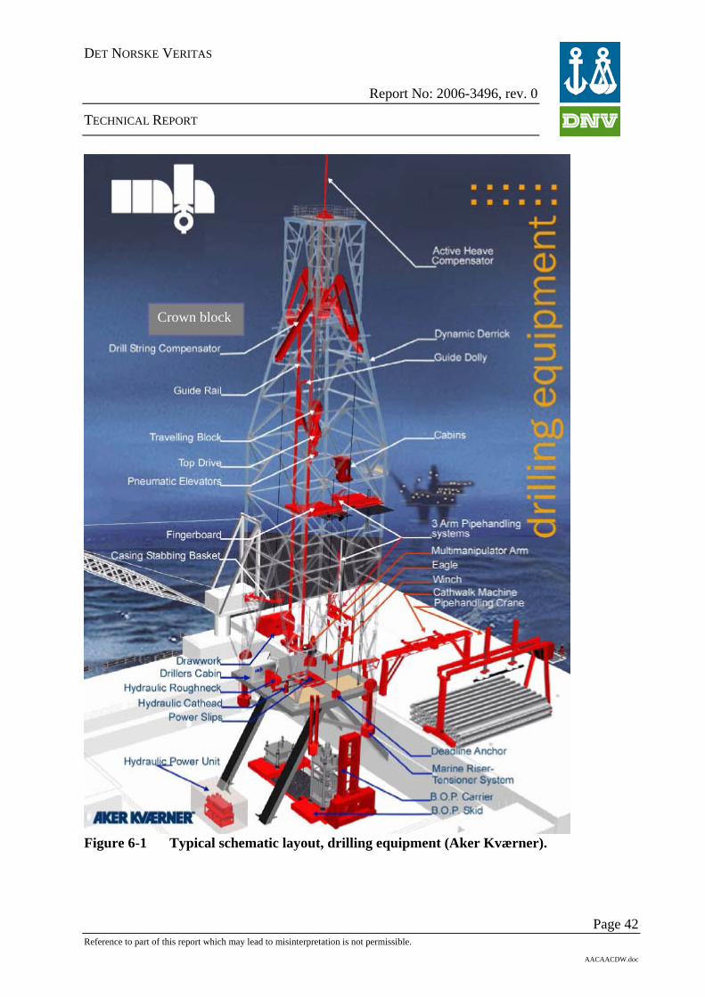
DET NORSKE VERITAS
Report No: 2006-3496, rev. 0
TECHNICAL REPORT
Page 42
Figure 6-1 Typical schematic layout, drilling equipment (Aker Kværner).
Crown block
Reference to part of this report which may lead to misinterpretation is not permissible.
AACAACDW.doc
DET NORSKE VERITAS
Report No: 2006-3496, rev. 0
TECHNICAL REPORT
6.4.1 Pipe handling The pipe handling system often experiences mechanical wear due to frequent use. Components experiencing such wear should be inspected periodically. Furthermore, impacts and vibration during pipe handling might lead to loss of pretension in bolted connections. Loss of pretension increases the probability for fatigue damage in the connections. The pretension of the bolted connections should be checked periodically during the design life.
6.4.2 Main hoisting system The brake capacity of the brakes on the draw work might get reduced due to oil contamination on the discs. An important aspect of draw work brakes is the friction between the brake pads and the discs. The friction factor used in the brake design calculations is to DNV’s experience often non-conservative. The main brake is an electric motor, and the driller training using the brake system is often not satisfactory, which leads to potential hazardous situations. This also includes that some drilling rigs uses the emergency brake on a daily basis in the drilling operation, which reduces the safety level in the main hoisting system. If the pads are not “run-in” properly, a reduced brake capacity will be experienced. This may not be noticed during normal operations, but may lead to an accident in an emergency braking operation. The disc springs of the callipers are subjected to low-cycle fatigue which reduces the brake capacity after 1-2 years of operation. The fabrication tolerances of the callipers are sometimes too inaccurate, which give a higher airgap for the disc brakes and following loss of brake effect on one of the sides. The travelling block/crown blocks are often experiencing mechanical wear in sheave grooves during their life time. The safety level of the draw work and the crown block should be at the same level. The crown block safety level is less than the draw work, which has lead to hazardous situations during accidental events where details in the crown block have collapsed. In general, the development of the drilling operations goes toward higher hook loads, resulting in a need for corresponding increased brake capacity.
6.4.3 Control systems Experience shows that Control systems sometimes contain programming errors, leading to logical errors in the system and planned operations fail. After a few years in operation, whole or parts of a control system might be upgraded. The quality control of the new control system is often not as extensive as when the drilling system was initially designed, manufactured and tested. Experience shows that such upgrading sometimes lead to unwanted events. Safety assessments when upgrading control systems should be increased to prevent uncontrolled situations/operations. In the draw work, several control systems from different vendors are often not sufficiently correlated. This aspect gives a source for failure during operation. To prevent this source for failure, one of the vendors should be given the main responsibility with respect to total quality assurance, documentation and interface aspects.
6.4.4 Iron Roughneck and pipe racking system The iron roughneck as well as the pipe racking system experiences extensive mechanical wear, and are often replaced/upgraded after 4-5 years.
Page 43 Reference to part of this report which may lead to misinterpretation is not permissible.
AACAACDW.doc

DET NORSKE VERITAS
Report No: 2006-3496, rev. 0
TECHNICAL REPORT
6.4.5 Steel wire ropes Steel wire ropes are subject to continuous wear and fatigue loading. On drawwork and riser tension system there is implemented a ton*mileage measuring device. After a specific ton*mileage the cut and slip is carried out. It is normal procedure to send part of the used wire to a test laboratory in order to calibrate the acceptance level for cut& slip. Worn steel wire ropes may be reduced in diameter due to roll out and fatigue cracks may be introduced. If steel wire rope are subject to high temperature from for example flaring the wire grease may be lost which lead to more rapid degradation of the wire than expected. Damage to wire, caused by kinking, running over sharp edges or due to bad spooling on winches are common causes of replacement for wires in winches. Winches which lack spooling devices may experience incorrect spooling. This effect gives uneven contact on the wire and leads to higher wear on the wire.
6.4.6 Sealed machinery In general, we have experienced that closed sealed machinery sometimes are not properly sealed, and contamination is able to enter and cause extensive mechanical wear on the machinery. This is hidden errors which are not found during external visual inspection. Typical examples: splines and bearings.
6.4.7 Drill string The drill string often experience fatigue cracking due to ageing and poor control with the number of load cycles. The handling and use of the drill string give small damages which lead to corrosion, which accelerates fatigue (i.e. corrosion fatigue as described in Section 2.1.4) and thereby give a fatigue weakness and damage. High differential pressures combined with eroding environment might lead to wash-out of the drill string as shown in Figure 6-2.
Page 44 Reference to part of this report which may lead to misinterpretation is not permissible.
AACAACDW.doc

DET NORSKE VERITAS
Report No: 2006-3496, rev. 0
TECHNICAL REPORT
Figure 6-2 Typical example wash-out of drill string (DNV photo).
6.4.8 Drilling riser The drilling riser is often designed with a smaller thickness amendment due to corrosion than other risers and structures, but should be subject to a higher control regime. Reduced wall thickness due to corrosion and erosion leads to a reduced tension capacity. Through the riser management system on the rig, there should be a system to rotate the position of the riser elements periodically to be in the splash zone as well as in the highest loaded positions in turn. There should also be a load record of the riser stack giving an overview of the loading of each component.
6.5 Blow Out Preventer (BOP)
Page 45
The gaskets of the BOP are often subject to a continuous mechanical wear during the drilling operation as well as periodic testing of the BOP. In some kinds of BOPs, the shear ram can wear out after only approx. 15 runs. In such cases, it is of vital importance that the operator has exact control of the history of the BOP, and that the critical gaskets are replaced before leaks occur. Degradation and damage of some of the BOP gaskets can increase significantly due to special operations such as drilling through casing where steel swarf from the drilling operation passes
Reference to part of this report which may lead to misinterpretation is not permissible.
AACAACDW.doc

DET NORSKE VERITAS
Report No: 2006-3496, rev. 0
TECHNICAL REPORT
the BOP. The feasibility of the gaskets is periodically controlled by pressure tests demonstrating that the functionality of the BOP is maintained.
6.6 Subsea Wellhead The Subsea wellhead is normally manufactured from relatively high strength low alloy CMn steel. Sealing surfaces are normally inlay welded with CRA. The wellhead are welded to a casing pup piece, often manufactured by API 5L grade materials. Current analysis shows that the intended design and mechanical behaviour are dependant of the level and quality of cement fill between 20” casing and 30” conductor. The different mechanical behaviour is of particular importance for the wellheads capacity to take riser fatigue loads. Current design load as defined by NORSOK U-001 are not sufficient to describe the capacity to a wellhead system. Recent work by DNV also indicates that the wellhead does not provide the same level of conservatism as the common industry standard for completion/work over risers. The potential damage to Subsea wellheads are related to drilling or workover mode when the wellheads are subjected to a riser load. The failure mode is related to fatigue, both in welds as well as at stress risers in base material. As described in Section 2.1.3 in this document, a fatigue failure will have an initiation stage with slow propagation before reaching a limit where remaining cross section is overloaded and a rapid failure develops. The wellheads are normally not accessible for inspection, and hence it is difficult to detect cracks that are in initiation stage. Recent assessments of fatigue lifetime show that the wellheads are utilised at a level exceeding already used time with riser exposure. This is particularly important when assessments of old wellhead systems are done with respect to IOR programmes which may lead to extended riser exposure.
6.6.1 Workmanship The Subsea wellheads are manufactured of relatively high strength CMn steel. As the wellheads can show short fatigue life, it is important that they are designed with profiles that give low stress concentration factors. All welding and heat treatment must be done according to approved procedures and subsequently inspected by NDT. The fatigue resistance of welds is very dependant of the weld configuration. A weld that is grinded after welding will have a better fatigue life compared to a non machined weld. However, it is of importance that the weld between 18 ¾” wellhead housing to 20” casing weld gives limitation to final surface treatment after welding. This is due to restricted access for personnel, due to long assembly and small internal diameter. The cement job in the annuli between 20” and 30” casings is difficult to check. Cement will be contaminated as well as it is of low strength type with low viscosity. During curing it will shrink and give less support. Thermal expansion due to temperature variations will also decrease the supporting effect from the cement. This can be unfavourable with respect to the fatigue life of the 20” casing and its welds.
6.7 Conductors The conductors are normally manufactured from low alloy carbon steel and are dependant of cathodic protection against external corrosion. As mentioned above for Subsea wellheads, the conductors are also welded to nominal thickness API 5 L grade steel materials. This weld together with stress risers from changes in cross sectional area are all elements that can give
Page 46 Reference to part of this report which may lead to misinterpretation is not permissible.
AACAACDW.doc

DET NORSKE VERITAS
Report No: 2006-3496, rev. 0
TECHNICAL REPORT
reduced fatigue life capacity to the wellhead system. Fatigue loads are experienced by the conductor when it is subjected to completion/workover risers- as well as to a drilling riser set up. The conductor capacity is dependant of quality and support externally provided by grouting and strength capacity to surrounding sea bed. The conductor capacity is also influenced by lateral support from a template system. In other words, a satellite conductor without support from a template structure is exposed to higher external loads. This leads to lower static capacity and shorter fatigue life.
As mentioned above for Subsea wellheads, the conductors’ mechanical behaviour are not always as expected through design. It is a combined unit with wellhead and they are having a mechanical interaction that depends on factors mentioned above, such as external grouting and internal cement quality in the annuli between 20” and 30”.
For combinations of the factors above, the wellhead/conductor capacities to riser fatigue load can be relatively small. In some cases they are calculated to as low as shorter than a normal duration of an intervention campaign. Therefore the wellhead and conductor show lower conservatism than what is acceptable for a riser set-up.
It is important to include such evaluations into the process when IOR programmes or other programmes are discussed that lead to extended riser exposure to existing wellhead system.
The conductors are easier to inspect compared to the wellhead housing. However, the most severe failure mode, fatigue might be impossible to inspect for. Also due to most critical weld might be in an area where external inspection is impossible due to external frames, and internally due to all casings that is installed.
6.7.1 Workmanship The conductor is constructed of mild steel. It is not pressure containing so it is only seeing mechanical load. Robustness to fatigue life is very dependant on the quality of the weld. Compared to wellhead housings, the weld between conductor housing and conductor casing is possible to both grind and inspect. However, it is not certain that this have been accounted for at the time of design and manufacture to old systems. External grouting and possible fracturing of the seabed is factors that can lead to reduced capacity to both static bending loads as well as fatigue load. A template installed conductor is normally better in those respects than satellite wells.
6.8 Production casing in wells Depending on the well behaviour, the Production casing and other components in the completion string will be subject to corrosion and erosion. For wells with a high degree of sand production, erosion (see Section 2.1.1) will be a relevant degradation mechanism. For wells subject to gas lift, frequent start/stop, water production or varying injection of water/gas, corrosion will be the main degradation mechanism. Geotechnical scenarios like settlements, dislocations, etc., can introduce additional shear and compression loads, and should be taken into account in the design. Detection of damaged production casing is primarily performed by pressure surveillance, and there are a number of quality control and surveillance methods of production casing with respect to thickness measuring.
Page 47 Reference to part of this report which may lead to misinterpretation is not permissible.
AACAACDW.doc

DET NORSKE VERITAS
Report No: 2006-3496, rev. 0
TECHNICAL REPORT
6.9 High pressure tubing and manifolds for circulation of drill mud In high pressure systems, erosion will be the main degradation mechanism. Especially in choke- and kill manifolds during well control situations, very large erosion rates will appear due to the mixture of gas and drilling slurry. Also in high-pressure piping handling drill mud and cement, erosion is the main degradation mechanism, especially in bends and branches.
6.10 Recertification of well control equipment The content of this section is mainly extracted from ref. /1/. It is DNV’s interpretation of the PSA regulations that a major overhaul/inspection with verification of Blow Out Preventers and other pressure control equipment used for Drilling, Completion and Workover operations, should be performed at least every five years. In addition, the need to recertify equipment can occur due to several other causes:
- Change of intended use / loading aspects - Increasing original design life - Repair of equipment
The purpose of this inspection is to verify and document that the equipment condition and properties are within the original acceptance criteria.
The extent of inspection may be influenced on the following parameters: • Repair history • Maintenance history • Operational history • Manufacturers guidelines • Change in rules and regulations or company’s governing documents The following activities shall be included in the recertification process: • Review of original documentation with special focus on traceability. • Review of maintenance history/records, to verify the amount of use and extent of
maintenance • Stripping/dismantling of equipment • Visual inspection. • NDT • Dimensional check of selected components/review of dimensional check reports. • Change out of seals, treads etc. • Reassembly – recoating - preservation • Load/pressure testing and functional testing. The acceptance criteria for the various inspections performed shall be based on the manufacturer’s initial qualification programs and engineering documentation, as well as internationally recognized codes and standards.
DNV does not recommend recertifying equipment unless the acceptance criteria applied gives a certain confidence with regards to margins to failure. It must be possible to verify that the
Page 48 Reference to part of this report which may lead to misinterpretation is not permissible.
AACAACDW.doc
DET NORSKE VERITAS
Report No: 2006-3496, rev. 0
TECHNICAL REPORT
functional, performance and safety margins of the equipment are within the original acceptance criteria.
6.11 References /1/ DNV-OTG-06 Recertification of well control equipment – service description, September
2005
Page 49 Reference to part of this report which may lead to misinterpretation is not permissible.
AACAACDW.doc
DET NORSKE VERITAS
Report No: 2006-3496, rev. 0
TECHNICAL REPORT
7 MOORING SYSTEM
7.1 Introduction A Mooring Integrity JIP carried out by Noble Denton Europe /1/ has concluded as follows: - The interface between the surface vessel and the mooring line requires particular attention for
all types of FPS. - Carefully planned innovative1 inspection, making use of all possible tools, has been
demonstrated to be able to detect problems relatively early before they become a potential source of failure.
- At present no in-water techniques exist to check for possible fatigue cracks. - On two North Sea FPSs chain wear and corrosion have been found to be significantly higher
than what is specified by most mooring design codes. This wear seems to be more pronounced on less heavily loaded leeward lines compared to the more loaded windward lines.
- At present there is little data available which indicates how the break strength of long term deployed mooring components will be reduced by wear, corrosion including pitting and the possible development of small fatigue cracks.
- A possible contributory mechanism for the relatively high line failure rate among drilling semi-submersibles has been identified. This is believed to be due to rigs thinking they have set up balanced pre-tensions, when in fact this has not been achieved. One reason can be that the load cells on the windlasses are not calibrated properly. If the tension meters are well positioned, working properly and their calibration is in date, a likely cause of unbalanced line tensions is partial seizure of the gypsy wheels. This can be confirmed by a simple line Payout/Pull-In test. If this reveals that some of the gypsy wheels are partially seized, an attempt should be made to free them up. However, if the unit is on station it may not be feasible to undertake such work in situ. In such a case the line tensions out with the fairlead should be determined by other measures such as:
o ROV or possibly diver monitoring of the chain angles where they emerge from the fairleads
o Acoustic monitoring of the x, y and z positions of specific connectors on the mooring lines
From these measurements it is possible to back calculate the actual line tensions as long as this is done in calm conditions with minimal tidal variations.
7.2 Fairleads and chain stoppers Typical problems with fairleads are malfunction of bearings, excessive wear and tear in fairlead wheels and pockets due to insufficient support for chain. This may be caused by low tension and/or the fairlead is not rotating with the chain, which may be caused by bearing problems. Excessive wear and tear has been discovered in cases were the chain is terminated in chain stoppers underneath the unit.
Page 50
1 The mooring systems of mobile offshore units are inspected onshore within a period of 5 years. For units permanently installed at a location the inspection has to be carried out offshore and it is important to use all possible available tools. In situ water inspection techniques are continuing to improve, but further developments are needed to provide dimensional data on links all around the inter-grip area and to improve the marine growth cleaning off speed. For further information see /1/.
Reference to part of this report which may lead to misinterpretation is not permissible.
AACAACDW.doc

DET NORSKE VERITAS
Report No: 2006-3496, rev. 0
TECHNICAL REPORT
7.3 Chain Historically, chain manufactured in the 1980’s, especially Grade 4 chain suffered with quality control problems and subsequent brittle fracture problems. Brittle fracture is the term used for a rapid failure of material, which involves low ductility. It is partly dependent on the type of steel used, or the processing that it has been subject to, and is exacerbated by stress-raisers or cracks in the material. It can result in the failure of chains at relatively low tensions. The problem with brittle fracture is that the propensity of the material to fail in this way is not obvious to the naked eye and can only be quantified by destructive testing. Steel is more susceptible to brittle fracture when the yield strength is high or where the operational temperatures are low. The welding process, and subsequent heat treatment, used to form the chain link during manufacture must be very carefully controlled to prevent brittle fracture problems with chain. This said the metallurgical and manufacturing issues appear to have been largely resolved such that modern high strength chain can now be consistently produced. Much of this problematic chain has now been removed or scrapped but the associated problems have had an impact on the industry over the years /2/. It is also possible that there is a residual amount of this chain around. The prime cause of line failure now appears to be with the connecting shackles or with links that have been mechanically damaged. Common modes of failure in chain systems therefore include: - Mechanical damage to links - Missing or loose studs - Failure of connecting links - Brittle fracture of links (not so common with improved quality control of chain) - Fatigue Missing or loose studs has no directly influence on the breaking strength, however the stress distribution in the link is changed and the footprint will represent an area where fatigue cracks can develop and result in fatigue failure of the link. Control with stud pressing is essential and instances have been seen where studs have been pressed without having been correctly seated in the imprints. Also, studs have been expanded by excessive amounts with detrimental effect on the links. Ideally, stud pressing should result in light contact with the link. There is no limitation regarding how many times a stud can be pressed. The following tolerances regarding studs apply /8/: - Axial stud movement up to 1 mm is acceptable. - Axial stud movement greater than 2 mm is unacceptable. - Links are to be removed or studs are to be pressed using an approved procedure. - Acceptance of axial stud movement from 1 to 2 mm must be evaluated based on the
environmental conditions of the unit’s location and expected period of time before the chain is again available for inspection.
- Lateral movement up to 4 mm is acceptable provided there is no realistic prospect of the stud falling out.
- Welding of studs is not acceptable.
Page 51 Reference to part of this report which may lead to misinterpretation is not permissible.
AACAACDW.doc
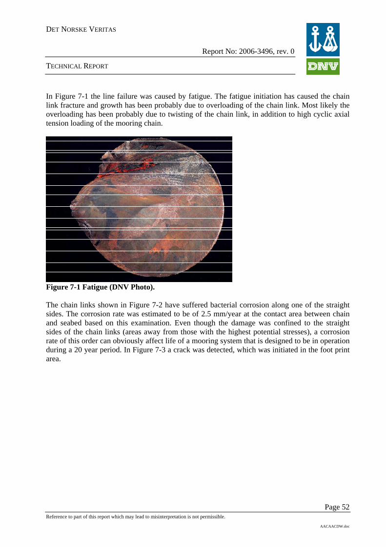
DET NORSKE VERITAS
Report No: 2006-3496, rev. 0
TECHNICAL REPORT
In Figure 7-1 the line failure was caused by fatigue. The fatigue initiation has caused the chain link fracture and growth has been probably due to overloading of the chain link. Most likely the overloading has been probably due to twisting of the chain link, in addition to high cyclic axial tension loading of the mooring chain.
Figure 7-1 Fatigue (DNV Photo). The chain links shown in Figure 7-2 have suffered bacterial corrosion along one of the straight sides. The corrosion rate was estimated to be of 2.5 mm/year at the contact area between chain and seabed based on this examination. Even though the damage was confined to the straight sides of the chain links (areas away from those with the highest potential stresses), a corrosion rate of this order can obviously affect life of a mooring system that is designed to be in operation during a 20 year period. In Figure 7-3 a crack was detected, which was initiated in the foot print area.
Page 52 Reference to part of this report which may lead to misinterpretation is not permissible.
AACAACDW.doc

DET NORSKE VERITAS
Report No: 2006-3496, rev. 0
TECHNICAL REPORT
Figure 7-2 Bacterial corrosion (DNV classed FPSO offshore West Africa).
Figure 7-3 Crack initiated in the stud foot print (DNV photo). Figure 7-4 shows severe wear and tear in a long term mooring system.
Page 53 Reference to part of this report which may lead to misinterpretation is not permissible.
AACAACDW.doc

DET NORSKE VERITAS
Report No: 2006-3496, rev. 0
TECHNICAL REPORT
Figure 7-4 Wear and tear in chain links (Photo Norsk Hydro).
7.4 Recertification of chain Normally recertified chain is not accepted in long term mooring. However, for drilling units it is more common to rent used chain if the unit’s own mooring system is not sufficient for a new location. Recertification of chain shall be carried out applying the same inspection requirement as for a complete periodical survey, which include visual examination, extensive non-destructive testing, dimension control and pressing of studs.
A recertified chain for mobile offshore units shall pass the requirements for renewal survey given in DNV Instruction to surveyor /8/. It is generally not possible to state that a recertified chain is as good as a new equivalent chain. However, the recertified chain is found good enough for 5 year in operation, since a renewal survey is required every 5 years. Recertified chain is normally not accepted for permanent installations.
7.5 Synthetic fibre ropes Typical failure mechanisms are: - Ingress of particles - Mechanical damage during installation and hook up activities - Mechanical damage caused be fishing activities - Creep Ingress of particles such as sand or clay into the load bearing part of the fibre rope will reduce the breaking strength of the fibre rope significantly. This problem can be avoided by installing a filter underneath the outer jacket of the fibre ropes. DNV has qualified such filters for Marlow Ropes /3/ and ScanRope /4/.
Page 54 Reference to part of this report which may lead to misinterpretation is not permissible.
AACAACDW.doc

DET NORSKE VERITAS
Report No: 2006-3496, rev. 0
TECHNICAL REPORT
Mechanical damage during installation, hook up and ROV operations must be avoided. Further, trawling has caused failure of fibre ropes. DNV has developed a recommended practice /5/ to assess the rest capacity of a damaged fibre rope. The purpose of this recommended practice is to provide assessment basis for the suitability of a polyester mooring rope to remain in service, after it has been mechanically damaged by external objects. The recommended practice is applicable to any "parallel-subrope" type of rope. The inputs required to perform the necessary calculations are provided by the rope manufacturer. This information is given in the Manufacturer's Report. The damage assessment is based on the subrope-to-rope relationship, since the subrope is the primary building block of the rope. Subrope-to-rope assessment is required since the effect of damage is highly dependent on the damage distribution. This implies that for a given loss of area, the resulting rope strength and fatigue performance will vary depending on the distribution of the damage. Synthetic ropes have become an accepted alternative to chain and steel wire rope mooring lines in recent years. At present, polyester fibre is the most widely used synthetic fibre for this purpose. High modulus polyethylene (HMPE) is an alternative to polyester, with many favourable properties. However, HMPE is more susceptible to creep than polyester, and this behaviour requires careful assessment as part of the design process for HMPE mooring lines. Creep is a form of permanent elongation of synthetic fibres. The creep rate increases with increasing specific load and temperature. Creep can ultimately lead to failure of a mooring line. Creep need not be a serious problem if it is properly accounted for in the design of a mooring line.
7.6 Steel wire ropes There are three types of steel wire ropes used in mooring systems (see Figure 7-5) with different expected service life: - Six and multi strand, normally used by mobile offshore units. - Spiral strand with and without plastic sheathing, normally used by permanent installed units. - Half and fully locked coil with or without plastic sheathing, normally used by permanent
installed units.
Page 55 Reference to part of this report which may lead to misinterpretation is not permissible.
AACAACDW.doc
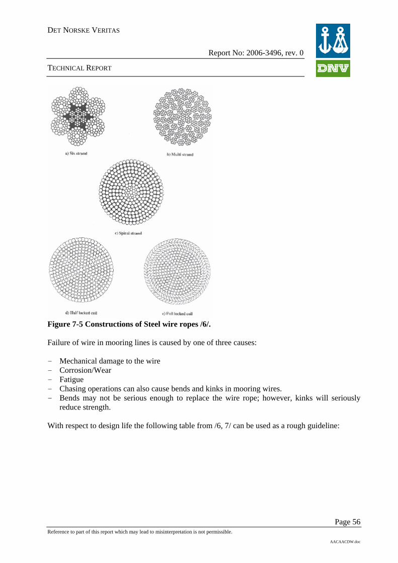
DET NORSKE VERITAS
Report No: 2006-3496, rev. 0
TECHNICAL REPORT
Figure 7-5 Constructions of Steel wire ropes /6/. Failure of wire in mooring lines is caused by one of three causes: - Mechanical damage to the wire - Corrosion/Wear - Fatigue - Chasing operations can also cause bends and kinks in mooring wires. - Bends may not be serious enough to replace the wire rope; however, kinks will seriously
reduce strength. With respect to design life the following table from /6, 7/ can be used as a rough guideline:
Page 56 Reference to part of this report which may lead to misinterpretation is not permissible.
AACAACDW.doc

DET NORSKE VERITAS
Report No: 2006-3496, rev. 0
TECHNICAL REPORT
Choice of steel wire rope construction
Possibilities for replacement of wire rope segments
Field design life (years) Yes No < 8 A/B/C A/B/C 8 – 15 A/B/C A/B > 15 A/B A A) Half locked coil/full locked coil/spiral strand
with plastic sheathing B) Half locked coil/full locked coil/spiral strand
without plastic sheathing C) Six strand/multi strand
A common design requirement is that wire rope segments in mooring lines are to be protected against corrosion attacks throughout the design life. The wire rope is therefore assumed to be fully protected such that its fatigue life approaches that in air. This is normally ensured by the following measures or combinations thereof: - Sacrificial coating of individual wires. - Application of blocking compound on each layer of the strand during stranding. The
compound should fill all crevices in the wire rope, strongly adhere to individual wire surfaces and have good lubrication properties.
- Cathodic protection by spinning zinc or other sacrificial anode alloy wires in one of the outer 3 layers of wire rope during manufacture.
- Surface sheathing of the wire rope by an extruded plastic jacket in order to prevent ingress of sea water and flushing out the blocking compound.
The ends of each wire rope segment are normally terminated with sockets. Free bending at the sockets outlet can reduce the wire rope fatigue life. To avoid premature fatigue failure, a bend limiting device is often incorporated at these locations. Such a device is designed to smoothly transfer the loads from the sockets to the rope. To prevent ingress of water in the socket a sealing system may be incorporated in the device.
Page 57 Reference to part of this report which may lead to misinterpretation is not permissible.
AACAACDW.doc

DET NORSKE VERITAS
Report No: 2006-3496, rev. 0
TECHNICAL REPORT
Page 58 Reference to part of this report which may lead to misinterpretation is not permissible.
AACAACDW.doc
7.7 References /1/ Floating production system - JIP FPS mooring integrity. Prepared by Noble Denton
Europe Limited for the Health and Safety Executive 2006
/2/ P. J. Donaldson, B.Sc. Master Mariner, MRINA M. Brown B.Sc., M.Sc., M.B.A., C.Eng., MRINA M. Pithie, Master Mariner: “Design and integrity management of mobile installation moorings”. Noble Denton Europe Ltd, 2004
/3/ DNV Report No. BGN-R3100270 “Test of Soil Filter”, July 2000
/4/ DNV Report No. 2005-3502 “Testing of Soil Filter”
/5/ DNV-RP-E304 “Damage Assessment of Fibre Ropes for Offshore Mooring”
/6/ DNV Certification Note No.2.5 “Certification of Offshore Mooring Steel Wire Ropes, May 1995
/7/ DNV-OS-E301 “Position Mooring”, October 2004
/8/ DNV Instruction to surveyors for Classification of Mobile Offshore Units, I-C3.4 Mooring System
- o0o -

DET NORSKE VERITAS
APPENDIX A
SUMMARY
Page A-1 Report No. 2006-3496, rev. 0
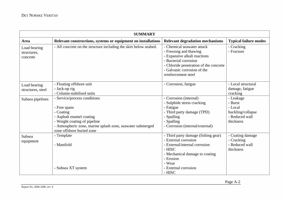
DET NORSKE VERITAS
SUMMARY
Area Relevant constructions, systems or equipment on installations Relevant degradation mechanisms Typical failure modes
Load bearing structures, concrete
- All concrete on the structure including the skirt below seabed. - Chemical seawater attack - Freezing and thawing - Expansive alkali reactions - Bacterial corrosion - Chloride penetration of the concrete - Galvanic corrosion of the reinforcement steel
- Cracking - Fracture
Load bearing structures, steel
- Floating offshore unit - Jack-up rig - Column-stabilised units
- Corrosion, fatigue
- Local structural damage, fatigue cracking
Subsea pipelines - Service/process conditions - Free spans - Coating - Asphalt enamel coating - Weight coating of pipeline - Atmospheric zone, marine splash zone, seawater submerged zone offshore buried zone
- Corrosion (internal) - Sulphide stress cracking - Fatigue - Third party damage (TPD) - Spalling - Spalling - Corrosion (internal/external)
- Leakage - Burst - Local buckling/collapse - Reduced wall thickness
Subsea equipment
- Template - Manifold - Subsea XT system
- Third party damage (fishing gear) - External corrosion - External/internal corrosion - HISC - Mechanical damage to coating - Erosion - Wear - External corrosion - HISC
- Coating damage - Cracking - Reduced wall thickness
Page A-2 Report No. 2006-3496, rev. 0
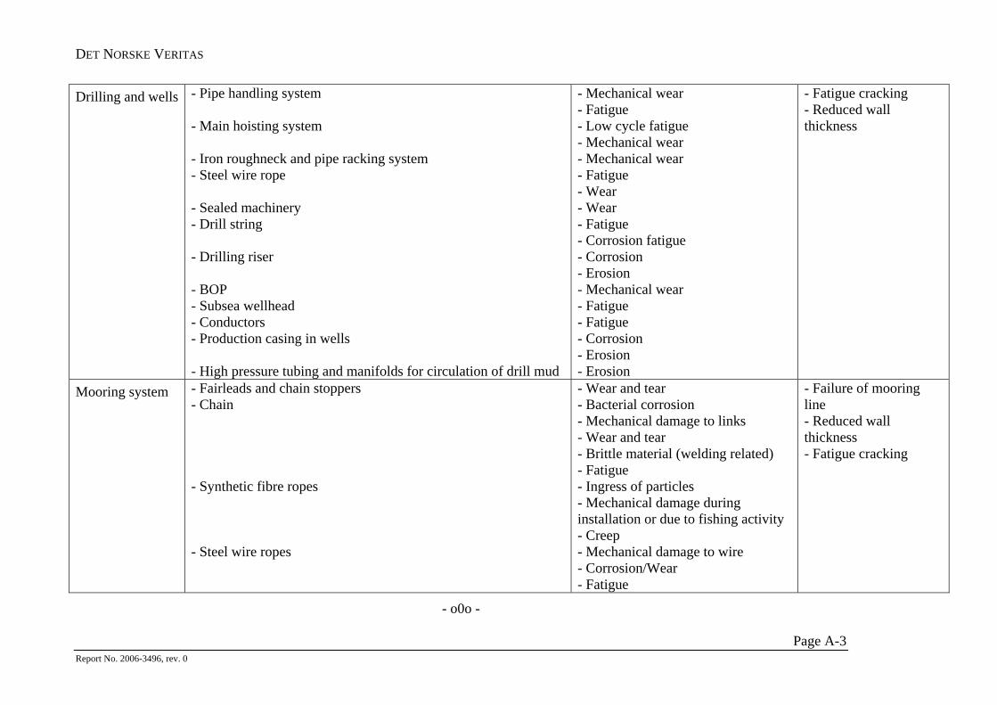
DET NORSKE VERITAS
Drilling and wells - Pipe handling system - Main hoisting system - Iron roughneck and pipe racking system - Steel wire rope - Sealed machinery - Drill string - Drilling riser - BOP - Subsea wellhead - Conductors - Production casing in wells - High pressure tubing and manifolds for circulation of drill mud
- Mechanical wear - Fatigue - Low cycle fatigue - Mechanical wear - Mechanical wear - Fatigue - Wear - Wear - Fatigue - Corrosion fatigue - Corrosion - Erosion - Mechanical wear - Fatigue - Fatigue - Corrosion - Erosion - Erosion
- Fatigue cracking - Reduced wall thickness
Mooring system - Fairleads and chain stoppers - Chain - Synthetic fibre ropes - Steel wire ropes
- Wear and tear - Bacterial corrosion - Mechanical damage to links - Wear and tear - Brittle material (welding related) - Fatigue - Ingress of particles - Mechanical damage during installation or due to fishing activity - Creep - Mechanical damage to wire - Corrosion/Wear - Fatigue
- Failure of mooring line - Reduced wall thickness - Fatigue cracking
- o0o -
Page A-3 Report No. 2006-3496, rev. 0