Material Influence on Mitigation of Stress Corrosion ... · tion of stress corrosion cracking...
10
Grant Brandal 1 Department of Mechanical Engineering, Columbia University, 500 W 120th Street, Mudd Rm 220, New York, NY 10027 e-mail: [email protected] Y. Lawrence Yao Fellow ASME Department of Mechanical Engineering, Columbia University, New York, NY 10027 e-mail: [email protected] Material Influence on Mitigation of Stress Corrosion Cracking Via Laser Shock Peening Stress corrosion cracking is a phenomenon that can lead to sudden failure of metallic components. Here, we use laser shock peening (LSP) as a surface treatment for mitiga- tion of stress corrosion cracking (SCC), and explore how the material differences of 304 stainless steel, 4140 high strength steel, and 260 brass affect their mitigation. Cathodic charging of the samples in 1 M sulfuric acid was performed to accelerate hydrogen uptake. Nontreated stainless steel samples underwent hardness increases of 28%, but LSP treated samples only increased in the range of 0–8%, indicative that LSP keeps hydrogen from permeating into the metal. Similarly for the high strength steel, LSP treat- ing limited the hardness changes from hydrogen to less than 5%. Mechanical U-bends subjected to Mattsson’s solution, NaCl, and MgCl 2 environments are analyzed, to deter- mine changes in fracture morphology. LSP treating increased the time to failure by 65% for the stainless steel, and by 40% for the high strength steel. LSP treating of the brass showed no improvement in U-bend tests. Surface chemical effects are addressed via Kel- vin Probe Force Microscopy, and a finite element model comparing induced stresses is developed. Detection of any deformation induced martensite phases, which may be detri- mental, is performed using X-ray diffraction. We find LSP to be beneficial for stainless and high strength steels but does not improve brass’s SCC resistance. With our analysis methods, we provide a description accounting for differences between the materials, and subsequently highlight important processing considerations for implementation of the process. [DOI: 10.1115/1.4034283] Keywords: laser shock peening, stress corrosion cracking, microstructure, fracture analysis Introduction When choosing which materials to implement into engineering designs what may often go overlooked is how mechanical stress influences corrosion behavior. Stress corrosion cracking (SCC) is a phenomenon where a corrosive environment effectively lowers the fracture strength of a material. Rather than traditional failure by corrosion, which is evident by a slow dissolution of the material, SCC occurs without warning. This lack of visual clues is what makes SCC of concern; its sudden cracking can lead to unpredict- able, catastrophic failure of integral parts. The biggest problem from a design perspective is that stress corrosion cracking is diffi- cult to make conclusive predictions of when and where it will occur. It is highly dependent on the specific material/environment pair, where a material that is resistant in one environment may become dangerously susceptible to SCC in other environments. The stress required for SCC can either be externally applied or be a residual stress from previous manufacturing processes. Some situations where this occurs are pipe taps and fittings, nuclear reactors, pressure vessels, or high strength pipeline steels. Brass is machinable and generally considered as corrosion resistant, but it is still susceptible to SCC, and when this does occur it can cause excessive damage. Small concentrations of ammonia are found to be the main cause for brass’s failure by SCC, where even the low concentrations found in drinking water can be problematic [1]. Residual stresses caused during installation—such as tightening of threaded components—can cause material failure. Other resid- ual stresses, most prominently those caused by welding, can make a material susceptible to SCC. Many of the pipelines found in chemical processing plants are at risk, as are pipelines for distribu- tion of gases. Recently, a natural gas pipeline rupture was attrib- uted to SCC, where a combination of the internal pressure and corrosive gas as well as the external soil moisture and movement combined to cause failure [2]. Another critical example of SCC’s concern is in nuclear reactors, where susceptibility and cracking has been extensively documented [3]. Additionally, the elevated temperatures and exposure to radiation compound the concern for premature failure of reactors. With the identification of SCC’s potentially catastrophic effects, the question arises as how to prevent this phenomenon from occurring. While proper selection of materials does help, sometimes further enhancement of a material’s SCC resistance must be provided by surface processing treatments. Shot peening has been identified as potentially beneficial, attributed to impart- ing a compressive residual stress upon the surface of the material [4]. But the macroscopic morphological changes caused by this process may be undesirable, and the precision unsuitable for small parts. Another method is heat treating the final piece to relieve residual stresses, but this is not always practical, especially on large parts such as nuclear reactor cores. Furthermore, the addi- tional effects of heat treating (grain refinement, oxide or precipi- tate formation) may be undesirable. Laser shock peening (LSP) is a surface treatment process that has the potential for helping to mitigate the effects of SCC without damaging other characteristics of the material. While originally developed for increasing the fatigue life of materials, LSP uses laser generated shock waves to impart compressive residual stresses onto the surface [5], with affected regions as deep as 1 mm into the metal, much deeper than traditional shot peening. Another benefit of LSP over other processes is that it maintains minimal changes on overall feature morphology and metallurgy, thus avoiding the requirement of modifications to the design. The capability of LSP to prevent SCC has previously been investigated 1 Corresponding author. Contributed by the Manufacturing Engineering Division of ASME for publication in the JOURNAL OF MANUFACTURING SCIENCE AND ENGINEERING. Manuscript received March 4, 2016; final manuscript received July 5, 2016; published online August 8, 2016. Assoc. Editor: Hongqiang Chen. Journal of Manufacturing Science and Engineering JANUARY 2017, Vol. 139 / 011002-1 Copyright V C 2017 by ASME Downloaded From: http://manufacturingscience.asmedigitalcollection.asme.org/ on 08/21/2016 Terms of Use: http://www.asme.org/about-asme/terms-of-use
Transcript of Material Influence on Mitigation of Stress Corrosion ... · tion of stress corrosion cracking...

Grant Brandal1Department of Mechanical Engineering,
Columbia University,
500 W 120th Street, Mudd Rm 220,
New York, NY 10027
e-mail: [email protected]
Y. Lawrence YaoFellow ASME
Department of Mechanical Engineering,
Columbia University,
New York, NY 10027
e-mail: [email protected]
Material Influence on Mitigationof Stress Corrosion Cracking ViaLaser Shock PeeningStress corrosion cracking is a phenomenon that can lead to sudden failure of metalliccomponents. Here, we use laser shock peening (LSP) as a surface treatment for mitiga-tion of stress corrosion cracking (SCC), and explore how the material differences of 304stainless steel, 4140 high strength steel, and 260 brass affect their mitigation. Cathodiccharging of the samples in 1 M sulfuric acid was performed to accelerate hydrogenuptake. Nontreated stainless steel samples underwent hardness increases of 28%, butLSP treated samples only increased in the range of 0–8%, indicative that LSP keepshydrogen from permeating into the metal. Similarly for the high strength steel, LSP treat-ing limited the hardness changes from hydrogen to less than 5%. Mechanical U-bendssubjected to Mattsson’s solution, NaCl, and MgCl2 environments are analyzed, to deter-mine changes in fracture morphology. LSP treating increased the time to failure by 65%for the stainless steel, and by 40% for the high strength steel. LSP treating of the brassshowed no improvement in U-bend tests. Surface chemical effects are addressed via Kel-vin Probe Force Microscopy, and a finite element model comparing induced stresses isdeveloped. Detection of any deformation induced martensite phases, which may be detri-mental, is performed using X-ray diffraction. We find LSP to be beneficial for stainlessand high strength steels but does not improve brass’s SCC resistance. With our analysismethods, we provide a description accounting for differences between the materials, andsubsequently highlight important processing considerations for implementation of theprocess. [DOI: 10.1115/1.4034283]
Keywords: laser shock peening, stress corrosion cracking, microstructure, fractureanalysis
Introduction
When choosing which materials to implement into engineeringdesigns what may often go overlooked is how mechanical stressinfluences corrosion behavior. Stress corrosion cracking (SCC) is aphenomenon where a corrosive environment effectively lowers thefracture strength of a material. Rather than traditional failure bycorrosion, which is evident by a slow dissolution of the material,SCC occurs without warning. This lack of visual clues is whatmakes SCC of concern; its sudden cracking can lead to unpredict-able, catastrophic failure of integral parts. The biggest problemfrom a design perspective is that stress corrosion cracking is diffi-cult to make conclusive predictions of when and where it willoccur. It is highly dependent on the specific material/environmentpair, where a material that is resistant in one environment maybecome dangerously susceptible to SCC in other environments.
The stress required for SCC can either be externally applied orbe a residual stress from previous manufacturing processes. Somesituations where this occurs are pipe taps and fittings, nuclearreactors, pressure vessels, or high strength pipeline steels. Brass ismachinable and generally considered as corrosion resistant, but itis still susceptible to SCC, and when this does occur it can causeexcessive damage. Small concentrations of ammonia are found tobe the main cause for brass’s failure by SCC, where even the lowconcentrations found in drinking water can be problematic [1].Residual stresses caused during installation—such as tighteningof threaded components—can cause material failure. Other resid-ual stresses, most prominently those caused by welding, can makea material susceptible to SCC. Many of the pipelines found in
chemical processing plants are at risk, as are pipelines for distribu-tion of gases. Recently, a natural gas pipeline rupture was attrib-uted to SCC, where a combination of the internal pressure andcorrosive gas as well as the external soil moisture and movementcombined to cause failure [2]. Another critical example of SCC’sconcern is in nuclear reactors, where susceptibility and crackinghas been extensively documented [3]. Additionally, the elevatedtemperatures and exposure to radiation compound the concern forpremature failure of reactors.
With the identification of SCC’s potentially catastrophiceffects, the question arises as how to prevent this phenomenonfrom occurring. While proper selection of materials does help,sometimes further enhancement of a material’s SCC resistancemust be provided by surface processing treatments. Shot peeninghas been identified as potentially beneficial, attributed to impart-ing a compressive residual stress upon the surface of the material[4]. But the macroscopic morphological changes caused by thisprocess may be undesirable, and the precision unsuitable for smallparts. Another method is heat treating the final piece to relieveresidual stresses, but this is not always practical, especially onlarge parts such as nuclear reactor cores. Furthermore, the addi-tional effects of heat treating (grain refinement, oxide or precipi-tate formation) may be undesirable.
Laser shock peening (LSP) is a surface treatment process thathas the potential for helping to mitigate the effects of SCC withoutdamaging other characteristics of the material. While originallydeveloped for increasing the fatigue life of materials, LSP useslaser generated shock waves to impart compressive residualstresses onto the surface [5], with affected regions as deep as1 mm into the metal, much deeper than traditional shot peening.Another benefit of LSP over other processes is that it maintainsminimal changes on overall feature morphology and metallurgy,thus avoiding the requirement of modifications to the design. Thecapability of LSP to prevent SCC has previously been investigated
1Corresponding author.Contributed by the Manufacturing Engineering Division of ASME for publication
in the JOURNAL OF MANUFACTURING SCIENCE AND ENGINEERING. Manuscript receivedMarch 4, 2016; final manuscript received July 5, 2016; published online August 8,2016. Assoc. Editor: Hongqiang Chen.
Journal of Manufacturing Science and Engineering JANUARY 2017, Vol. 139 / 011002-1Copyright VC 2017 by ASME
Downloaded From: http://manufacturingscience.asmedigitalcollection.asme.org/ on 08/21/2016 Terms of Use: http://www.asme.org/about-asme/terms-of-use

by several researchers. For example, LSP treatment of stainlesssteel has been found to increase the time-to-failure in boilingMgCl2 solutions of U-bend specimens, where the improvedbehavior was attributed to the residual compressive stress counter-acting the applied load [6]. While this is a simple explanation ofbeneficial effects, it does not capture the overall phenomenon,namely, the electrochemical effects are not taken into considera-tion. Even though LSP does not impart any thermal effects on thesurface, it still causes significant changes to the surface chemistryand microstructure. As proof, multiple researchers have shownthat LSP treatment increases the rest potential of metals duringpolarization testing [7]. Increased rest potentials are indicative ofmore inert surfaces, but in most cases, it was found that over timethe rest potential decayed back towards the initial, untreated level.
Across these previous investigations, it is clear that LSP has thepotential to effectively reduce the effects of stress corrosioncracking. But the mechanism driving the SCC resistance improve-ment has yet to be fully understood, where achieving this under-standing could lead to identification of scenarios that wouldbenefit the most as well as optimization of the process. In thispaper, we work to provide a further description of the mitigationeffects imparted by LSP, not just including stress analysis but alsoby providing a discussion of the microstructural and electrochemi-cal changes that make LSP a valuable tool for SCC mitigation, aswell as differences caused by material characteristics.
Background
Mechanisms of Stress Corrosion Cracking. Several differentfailure mechanisms have been proposed to explain the occurrenceof SCC, but no definitive consensus has been reached. This maybe a result of different mechanisms dominating under differentcircumstances. Some of these theories are hydride formation,hydrogen enhanced decohesion, hydrogen enhanced localizedplasticity, and adsorption-induced dislocation emission [8]. Inmany cases, the most preeminent factor and common theme arethe effect of hydrogen. Hydrogen present in the corrosive environ-ment can have negative effects by penetrating into the microstruc-ture of the metal, known as hydrogen embrittlement. When amaterial is stressed in tension, and the crystal lattice is elongated,hydrogen’s diffusivity becomes even more exaggerated. The addi-tional hydrogen atoms within the already stressed lattice maypush the material over its threshold by weakening the atomicbonding, and result in failure. But developing a simple relation-ship between applied stress and SCC occurrence cannot beachieved [9], illustrating the unpredictable nature of thephenomenon.
Once it has penetrated the metallic surface, the distribution andlocation of hydrogen throughout the lattice are important. Grainboundaries act as high diffusivity paths, allowing for deep pene-tration of hydrogen [10]. Cold working generates dislocationswithin the lattice structure, and these dislocations act as hydrogentrapping sites. It is most likely that the hydrogen atoms will befound in the trapping sites rather than interstitial locations [11],and as a result, the solubility of hydrogen raises with increasingdislocation density. With excessive amounts of hydrogen present,a material’s lattice becomes stressed and subsequently, its hard-ness is increased [12]. This enables measuring hardness increasesin materials exposed to hydrogen containing environments to beused as an indicator of the amount of hydrogen that has penetratedinto the lattice.
Laser Shock Peening. The physical configuration for LSPprocessing consists of an ablative layer placed in between a targetsurface and a confining layer [13]. Since the confining layer istransparent to the laser’s wavelength, upon irradiation the laserbeam passes through this layer and is absorbed into the ablativelayer. Using a sufficiently intense laser beam instantly vaporizesthe ablative layer causing it to expand. But the confining layer
restricts the expansion, and thus, a shock wave is generated andtravels into the material resulting in a compressive residual stress[14]. The metallic surface does not undergo any thermal effects,as all of the laser energy is absorbed by the ablative layer.
An important characteristic of materials’ corrosion responses isthe formation of a surface oxide layer. This layer can help to pas-sivate the material, preventing the occurrence of further corrosion.Stainless steel, for example, achieves its corrosion resistance fromthe formation of a chromium oxide layer, which encases and pro-tects the iron. Thickness and uniformity of such oxide layers arevery important, and therefore, any surface processing treatmenthas the potential to negatively impact the oxide layer. Addition-ally, the stress state on the surface influences the formation ofoxide layers as well [15]. Surface roughness also plays an impor-tant role in the initiation of stress corrosion cracking. Withincrevices on a material’s surface, hydrolysis may acidify the elec-trolyte so that the pH within the crevices does not match the pH ofthe bulk solution. This causes an increase in the surface’s anodicreactions. In this case, the applied stress works to open up andexpose more surface crevices.
Dislocation Generation. During LSP processing, the materialexperiences extremely high strain rates as the shock wave propa-gates through it, reaching levels as high as 106 s�1. This causesplastic deformation [16] as well as the formation of many latticedislocations. As stated above, dislocations act as trapping sites forhydrogen, whereby LSP can be used to alter the hydrogen behav-ior and distribution within the lattice. Hydrogen’s solubilityincreases with dislocation density and, subsequently, its diffusiv-ity decreases as described by the following equation [17]:
D ¼ DLCL
CL þ Cx 1� hxð Þ (1)
where D is the effective diffusivity, DL is the normal (defect free)diffusivity, CL and Cx are the concentrations in the lattice andtrapping sites, and h is the population fraction of available trap-ping sites.
Upon plastic deformation, the rate at which dislocation densityincreases will vary for different materials. Dislocation generationby plasticity has three stages: easy glide, dislocation multiplica-tion by tangling, and dynamic recovery. Each one of these stagescan be numerically described in terms of the rate of change of dis-location density . versus shear strain c, as derived in Malyginet al. [18]. For easy glide
d.dc
� �m
¼ vm ¼ bkmð Þ�1 ¼ dmb�1 (2)
where b is the Burgers vector and k is the average distancebetween dislocations and obstacles such as grain boundaries. Thesecond stage is described by
d.dc
� �f
¼ vf .1=2f vf � 10�2b (3)
The third and final stage, dynamic recovery is when dislocationannihilation occurs, by dislocations of opposite signs coming intocontact or by grain refinement
d.dc
� �a
¼ �va. va ¼x5=2
s l24p2asc
¼ b�1da xs � 0:5 (4)
where l is the shear modulus, a is a dislocation interaction con-stant, and sc is the critical resolved shear stress. Summation of thecombined effects and rearrangement of variables yields
011002-2 / Vol. 139, JANUARY 2017 Transactions of the ASME
Downloaded From: http://manufacturingscience.asmedigitalcollection.asme.org/ on 08/21/2016 Terms of Use: http://www.asme.org/about-asme/terms-of-use
d.dc� r� rsð Þh
¼ 1
2m3 albð Þ2 vm þ vf
r� rs
malb
� �� va
r� rs
malb
� �2" #
(5)
where h is the work hardening coefficient, r is stress, and rs is theyield stress. Thus, by use of Eq. (5), the rate of change of disloca-tion density versus strain (deformation) can be estimated based onmaterial characteristics.
Work Function and Corrosion Potential. It is evident that thecorrosive response of metals is dependent on surface characteris-tics, which leads one to desire ways to characterize the surface’selectrochemical behavior as it may lead to additional insightsregarding SCC behavior. One such characterization is to analyzethe work function. By definition, the work function is the amountof energy required to remove an electron from the surface, asexpressed by the equation
W ¼ �e1� Ef (6)
where e is the elementary charge, 1 is the vacuum electrostaticpotential, and Ef is the Fermi Level. Oftentimes, the work functionis discussed regarding photoelectric devices, but it can also beapplied to corrosion analyses, particularly as related to the opencircuit potential during polarization testing. A linear relationshipbetween increasing work functions and increasing rest potentialshas been reported, thus providing an empirical basis [19,20].Examinations of the validity of this relationship have been madeon iron surfaces exposed to humid environments, where it hasbeen concluded that work function analysis is an effective methodfor corrosion characterization [21].
Multiple factors can affect the work function, particularly stress,both applied and residual. The Fermi level depends upon electrondensity, leading some researchers to develop relationships betweenelastic stress and work function changes. Based on density func-tional theory, Wang et al. have modeled the distribution of atomsin Cu (100) and how applied loads affect their density and thuswork function [22]. They found that tensile strains decrease workfunction, while compressive strains cause work function increases.While this provides a good basis, the plastic deformation causedby LSP further complicates the discussion. Dislocations are latticeimperfections, regions where electrons may be more easily ejectedfrom the surface. Increasing the amount of plastic strain in coppersamples results in both decreased work function and decreased cor-rosion potential [23]. The competing effects elastic and plasticstrain have on work function is a trade-off that must be understoodin order to fully maximize the benefits LSP has on SCC.
Processing Concerns. With many different factors contribut-ing to LSP’s influence on corrosion response, it is of concern thatfocusing on improving one aspect could actually result in harminganother one. This leads to concerns that overprocessing of themetallic samples will start to undo any beneficial effects that hadbeen imparted. For example, while initially austenitic, stainlesssteel can experience martensite formation upon excessive defor-mation. The corrosion response of martensitic phases differs fromaustenitic ones, thereby destroying the material’s homogeneityand thus decreasing the corrosion resistance. Increased strain ratesalso cause more martensitic formation [24], making this a particu-lar concern for LSP. Cold working of metals may result in grainrefinement. While grain refinement is sometimes desirable forstrengthening a material, from a corrosion standpoint it can beharmful. Grain boundaries have lower work functions than thegrain interiors, so increased amounts of grain boundaries by grainrefinement may therefore be detrimental. Conversely, grain refine-ment could act as a barrier to crack propagation and have a benefi-cial effect on the SCC response. These concerns illustrate that in
order to optimize the LSP process for SCC resistance, all of theunderlying effects must be understood, where simply continuingto impact the surface with as many laser impulses as possible willnot be the most effective approach.
Experimental Procedure
Three different materials were investigated: stainless steel 304,AISI 4140, and 260 cartridge brass. The stainless steel had a brushedsatin finish and a thickness of 1.22 mm, the 4140 high strength steelwas 2.4 mm thick, while the brass was 1.6 mm thick. The confininglayer for LSP was 6.35 mm thick acrylic, and black electrical tapewas used as the ablative layer. A Continuum NY61 Nd:YAG laser,operating at 1064 nm provided 17 ns laser pulses at a repetition rateof 20 Hz. Laser spot sizes ranged from 0.9–1.1 mm in diameter whilepulse energies ranged from 125 mJ to 300 mJ. Topography measure-ments were made with a Zygo Optical Profilometer. For the U-bendtesting, two-stage bending was performed as specified in ASTMG30, with a radius of curvature of 4.05 mm for the stainless steel andbrass, and 8.5 mm for the 4140 steel. A 25 mm long region was LSPtreated in the center of the samples before bending. The stainlesssteel samples were exposed to a boiling magnesium chloride solutionat 155 �C, the brass to Mattsson’s Solution at room temperature, andthe 4140 steel to 3% NaCl at 80 �C. A PANalytical Xpert3 PowderX-ray diffraction (XRD) was used for microstructure analysis andmartensite detection, and a Hitachi S-4700 scanning electron micro-scope (SEM) was used for imaging. Cathodic charging was per-formed in 1 M sulfuric acid at a current density of 800 mA/cm2 for30 min. Work function measurements were made on a BrukerDimension FastScan AFM operating in Peak Force Kelvin probeforce microscopy (KPFM) mode and using PFQNE-AL probes. Thefinite element method (FEM) model was implemented in ABAQUS.
Results and Discussion
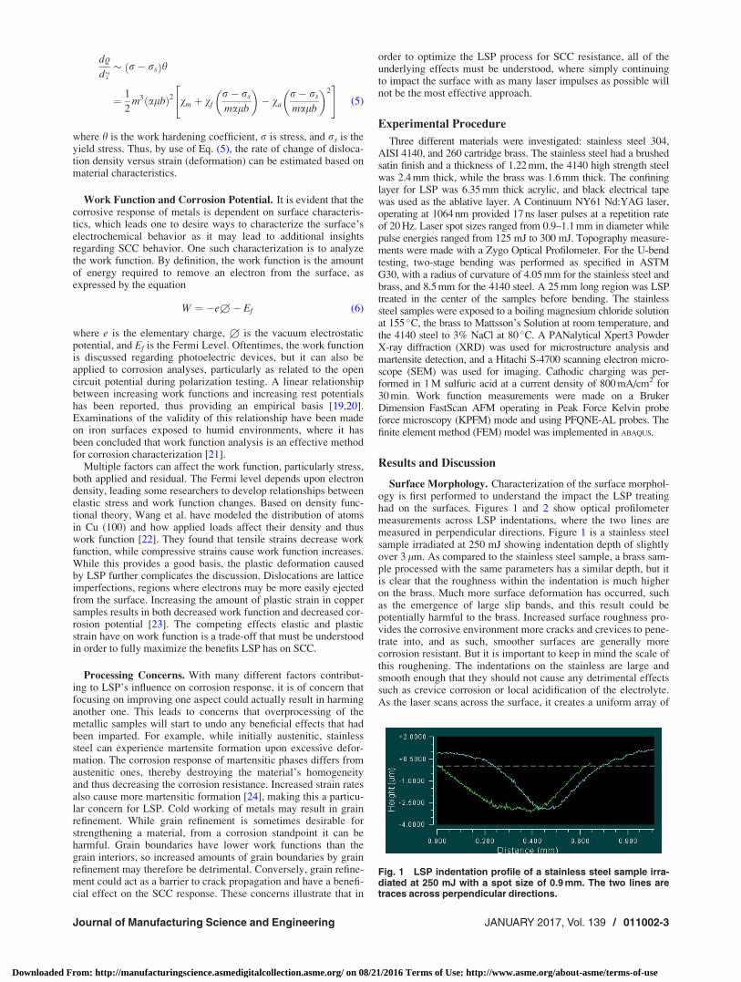
Surface Morphology. Characterization of the surface morphol-ogy is first performed to understand the impact the LSP treatinghad on the surfaces. Figures 1 and 2 show optical profilometermeasurements across LSP indentations, where the two lines aremeasured in perpendicular directions. Figure 1 is a stainless steelsample irradiated at 250 mJ showing indentation depth of slightlyover 3 lm. As compared to the stainless steel sample, a brass sam-ple processed with the same parameters has a similar depth, but itis clear that the roughness within the indentation is much higheron the brass. Much more surface deformation has occurred, suchas the emergence of large slip bands, and this result could bepotentially harmful to the brass. Increased surface roughness pro-vides the corrosive environment more cracks and crevices to pene-trate into, and as such, smoother surfaces are generally morecorrosion resistant. But it is important to keep in mind the scale ofthis roughening. The indentations on the stainless are large andsmooth enough that they should not cause any detrimental effectssuch as crevice corrosion or local acidification of the electrolyte.As the laser scans across the surface, it creates a uniform array of
Fig. 1 LSP indentation profile of a stainless steel sample irra-diated at 250 mJ with a spot size of 0.9 mm. The two lines aretraces across perpendicular directions.
Journal of Manufacturing Science and Engineering JANUARY 2017, Vol. 139 / 011002-3
Downloaded From: http://manufacturingscience.asmedigitalcollection.asme.org/ on 08/21/2016 Terms of Use: http://www.asme.org/about-asme/terms-of-use

indentations, of which a 3D topographical map is shown in Fig. 3for a brass sample. This pattern is for 0% overlapping betweenadjacent pulses, and good uniformity of the surface indentations isseen across the samples.
The occurrence of any phase transformations was investigatedwith XRD. Stainless steel samples were processed at 250 mJ, andthen in attempts to induce excessive deformation, the sampleswere reprocessed one and two more times. This gave three sam-ples with either one pass, two passes, or three passes, whereretreating the LSP sample compounds the shockwave’s effects.Austenitic stainless steel has large 2h diffraction peaks at43.58 deg, 50.79 deg, 74.70 deg, and 90.69 deg. The presence ofmartensite would cause the emergence of new diffraction peaks,because of the different lattice spacing of the martensite phase.Although other researchers have found deformation induced mar-tensite in LSP treated stainless steel samples, we detected no mar-tensite phases in any of our samples. In terms of corrosion, this isa positive result, as martensite’s presence would be detrimentalto the corrosion resistance.
Cathodic Charging and Hardness Increases. While LSP isknown to increase the surface hardness of metallic samples, theabsorption of hydrogen also can cause increases in hardness levelsnear the surface [25]. Cathodic charging is thus an effective wayfor performing accelerated testing of hydrogen uptake in metallicsamples. The excess electrons provided by the power supply reactwith the acidity of the corrosive environment to produce hydrogenmolecules. As the hydrogen permeates into the metal, it locallystresses the lattice, resulting in the measured hardness increase.Thus, the hardness changes are an indicator of the amount ofhydrogen influence that each sample has experienced.
Hardness increases induced by cathodic charging of stainlesssteel samples and 4140 high strength steel are plotted in Figs. 4and 5, respectively. Vickers hardness (HV) is determined by theequation
HV ¼ 0:0018544� L=d2 (7)
where L is the applied indenter load in grams, and d is theobserved diagonal length. Based on this relationship, and usingour applied load of 100 gf, we can estimate that for HV¼ 300 theindentation reached about 5 lm into the sample, indicating that byusing the low indenter load we are measuring in the near-surfaceregions that would experience the LSP effect. Five different proc-essing conditions are shown where the hardness for each respec-tive treatment level is plotted before and after cathodic charging.With increasing amounts of laser processing, there is a cleardecrease in the amount of hardness increase by cathodic charging.For untreated stainless steel samples, cathodic charging causednearly 30% hardness increases, while all of the LSP treated sam-ples underwent less than 10% increases, with the increase becom-ing statistically insignificant for the samples processed at 20% andtwo passes. The high strength steel shown in Fig. 5 underwentlower percent increases from both LSP and cathodic charging, butshow the same trend as for stainless steel. As this material ismuch less ductile than stainless steel, the 10% hardness increasein the untreated sample could still have significant detrimentaleffects.
LSP processing can influence the hydrogen behavior in variousways. First, it may act to prevent the initial entry of hydrogen intothe surface. But once the hydrogen has entered the lattice, the dis-locations generated from LSP will further prevent the hydrogenfrom diffusing deeper into the metal, where dislocations act astrapping sites for hydrogen. If there is insufficient energy toremove hydrogen from trapping sites, diffusion will be prevented,causing the hydrogen to remain near the surface. While a hydro-gen enriched region is of some concern, the potential it has fordecreasing the total amount of hydrogen that gets into the metalcould be a strength of LSP for preventing SCC.
U-Bend SCC Testing. The U-bend tests provide the mostdefinitive proof for the effectiveness of LSP processing on
Fig. 2 Indentation profile of brass LSP processed at 250 mJ.More surface roughening effects are visible than on the stain-less steel sample.
Fig. 3 Morphology of a patterned brass sample after LSP proc-essing. Individual indentations are still visible because of the0% overlap condition.
Fig. 4 Hardness increases after cathodic charging on stain-less steel samples, caused by increased hydrogen absorptioninto the lattice. The values on the abscissa correspond to theamount of overlapping between adjacent LSP pulses, and 2Xindicates that the surface was treated with two passes. As thelevel of LSP processing increases, the amount of hardnesschanges via hydrogen decreases.
011002-4 / Vol. 139, JANUARY 2017 Transactions of the ASME
Downloaded From: http://manufacturingscience.asmedigitalcollection.asme.org/ on 08/21/2016 Terms of Use: http://www.asme.org/about-asme/terms-of-use
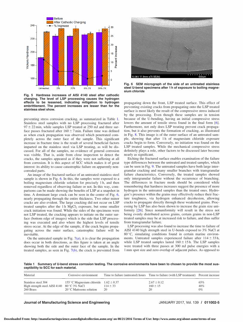
preventing stress corrosion cracking, as summarized in Table 1.Stainless steel samples with no LSP processing fractured after97 6 22 min, while samples LSP treated at 250 mJ and three sur-face passes fractured after 160 6 7 min. Failure time was definedas when crack propagation was observed which penetrated com-pletely across the outer face of the sample. This significantincrease in fracture time is the result of several beneficial factorsimparted on the stainless steel via LSP treating, as will be dis-cussed. For all of the samples, no evidence of general corrosionwas visible. That is, aside from close inspection to detect thecracks, the samples appeared as if they were not suffering at allfrom corrosion. It is this aspect of SCC which makes it of greatinterest: its ability to cause catastrophic failure on apparently non-corroded parts.
An image of the fractured surface of an untreated stainless steelsample is shown in Fig. 6. In this, the samples were exposed to aboiling magnesium chloride solution for precisely 1 h, and thenremoved regardless of observing failure or not. In this way, com-parisons can be made showing the benefits of LSP at a snapshot intime. A dominant large crack can be seen in the center of Fig. 6,nearly propagating through the entire thickness. Two other minorcracks are also evident. The large cracking did not occur on LSPtreated samples after the 1 h MgCl2 exposure, but some smallercrack initiation was found. While the sides of the specimens werenot LSP treated, the cracking appears to initiate on the outer sur-face (bottom edge of images) which is the side that LSP process-ing was executed and also where the highest levels of tensilestress occur. At the edge of the sample, if the crack begins propa-gating across the outer surface, catastrophic failure will beinevitable.
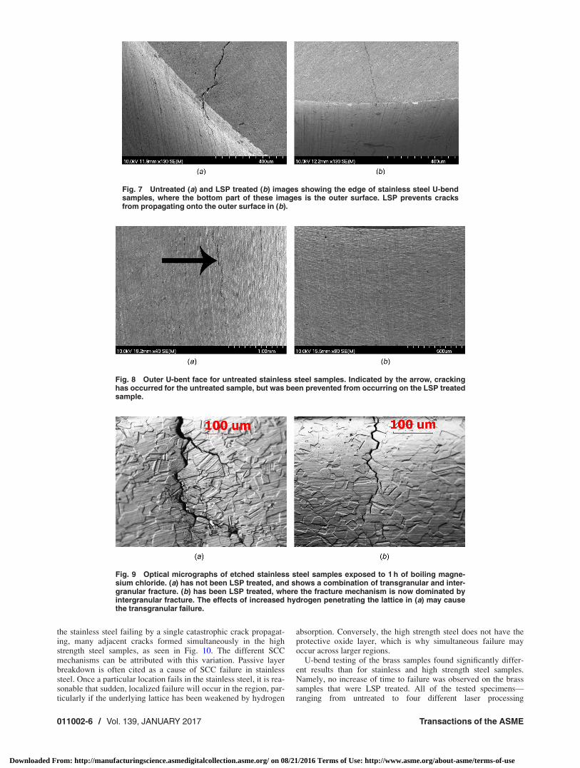
On the untreated sample in Fig. 7(a), it is clear the propagationdoes occur in both directions, as this figure is taken at an angleshowing both the side and the outer face of the sample. In thetreated samples, as seen in Fig. 7(b), the crack is prevented from
propagating down the front, LSP treated surface. This effect ofpreventing existing cracks from propagating onto the LSP treatedsurface is most likely the result of the compressive stress inducedby the processing. Even though these samples are in tensionbecause of the U-bending, having an initial compressive stresslowers the amount of tensile stress found in the final form [6].Furthermore, not only does LSP treating prevent crack propaga-tion, but it also prevents the formation of cracking, as illustratedin Fig. 8. This image is of the outer surface of an untreated sam-ple, showing that after 1 h of magnesium chloride exposurecracks begin to form. Conversely, no initiation was found on theLSP treated samples. While the mechanical compressive stressdefinitely plays a role, other factors to be discussed later becomenearly as significant.
Etching the fractured surface enables examination of the failuretype differences between the untreated and treated samples, whichcan be seen in Fig. 9. The untreated samples have both large inter-granular cracking and many smaller branches with transgranularfailure characteristics. Conversely, the treated samples showedonly intergranular failure without the occurrence of branching.The differences in fracture mode should be considered whileremembering that hardness increases suggest the presence of morehydrogen in the untreated samples than the treated ones. Hydro-gen’s presence within the grains may effectively reduce their frac-ture toughness, via hydrogen enhanced decohesion, allowingcracks to propagate directly through these weakened grains. Proc-essing by LSP has also been shown to increase the grain size uni-formity [26]. Since nonuniformity will result in the stress notbeing evenly distributed across grains, certain grains in non-LSPtreated samples may be at increased risk to failure, and thus sufferfrom transgranular failure.
LSP processing was also found to increase the time to failure ofAISI 4140 high strength steel in U-bends exposed to 3% NaCl at80 �C, simulating conditions found in certain marine environ-ments. Untreated samples experienced failure after 114 6 33 h,while LSP treated samples lasted 160 6 15 h. The LSP sampleswere treated with three passes at 300 mJ pulse energies with a1 mm spot size and zero overlap of adjacent pulses. As opposed to
Fig. 5 Hardness increases of AISI 4140 steel after cathodiccharging. The level of LSP processing causes the hydrogeneffects to be lessened, indicating mitigation to hydrogenembrittlement. The percent increases are lesser than for thestainless steel show.
Table 1 Summary of U-bend stress corrosion testing. The corrosive environments have been to chosen to provide the most sus-ceptibility to SCC for each material.
Material Corrosive environment Time to failure (untreated) hours Time to failure (with LSP treatment) Percent increase
Stainless steel 304 155 �C Magnesium chloride 1.62 6 0.37 2.67 6 0.12 65%High strength steel AISI 4140 80 �C 3% NaCl 114 6 33 160 6 15 40%260 Brass 20 �C Mattssons solution 20 20 0%
Fig. 6 SEM micrograph of the side of an untreated stainlesssteel U-bend specimens after 1 h of exposure to boiling magne-sium chloride
Journal of Manufacturing Science and Engineering JANUARY 2017, Vol. 139 / 011002-5
Downloaded From: http://manufacturingscience.asmedigitalcollection.asme.org/ on 08/21/2016 Terms of Use: http://www.asme.org/about-asme/terms-of-use
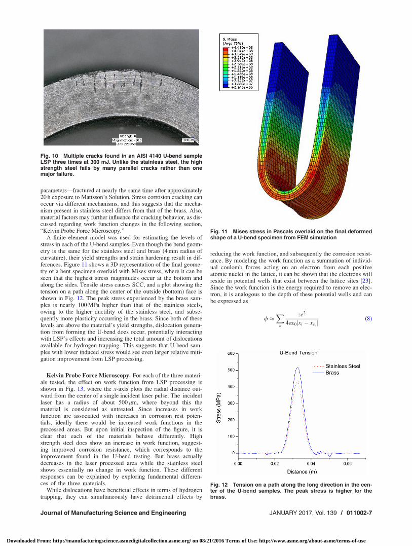
the stainless steel failing by a single catastrophic crack propagat-ing, many adjacent cracks formed simultaneously in the highstrength steel samples, as seen in Fig. 10. The different SCCmechanisms can be attributed with this variation. Passive layerbreakdown is often cited as a cause of SCC failure in stainlesssteel. Once a particular location fails in the stainless steel, it is rea-sonable that sudden, localized failure will occur in the region, par-ticularly if the underlying lattice has been weakened by hydrogen
absorption. Conversely, the high strength steel does not have theprotective oxide layer, which is why simultaneous failure mayoccur across larger regions.
U-bend testing of the brass samples found significantly differ-ent results than for stainless and high strength steel samples.Namely, no increase of time to failure was observed on the brasssamples that were LSP treated. All of the tested specimens—ranging from untreated to four different laser processing
Fig. 7 Untreated (a) and LSP treated (b) images showing the edge of stainless steel U-bendsamples, where the bottom part of these images is the outer surface. LSP prevents cracksfrom propagating onto the outer surface in (b).
Fig. 8 Outer U-bent face for untreated stainless steel samples. Indicated by the arrow, crackinghas occurred for the untreated sample, but was been prevented from occurring on the LSP treatedsample.
Fig. 9 Optical micrographs of etched stainless steel samples exposed to 1 h of boiling magne-sium chloride. (a) has not been LSP treated, and shows a combination of transgranular and inter-granular fracture. (b) has been LSP treated, where the fracture mechanism is now dominated byintergranular fracture. The effects of increased hydrogen penetrating the lattice in (a) may causethe transgranular failure.
011002-6 / Vol. 139, JANUARY 2017 Transactions of the ASME
Downloaded From: http://manufacturingscience.asmedigitalcollection.asme.org/ on 08/21/2016 Terms of Use: http://www.asme.org/about-asme/terms-of-use
parameters—fractured at nearly the same time after approximately20 h exposure to Mattsson’s Solution. Stress corrosion cracking canoccur via different mechanisms, and this suggests that the mecha-nism present in stainless steel differs from that of the brass. Also,material factors may further influence the cracking behavior, as dis-cussed regarding work function changes in the following section,“Kelvin Probe Force Microscopy.”
A finite element model was used for estimating the levels ofstress in each of the U-bend samples. Even though the bend geom-etry is the same for the stainless steel and brass (4 mm radius ofcurvature), their yield strengths and strain hardening result in dif-ferences. Figure 11 shows a 3D representation of the final geome-try of a bent specimen overlaid with Mises stress, where it can beseen that the highest stress magnitudes occur at the bottom andalong the sides. Tensile stress causes SCC, and a plot showing thetension on a path along the center of the outside (bottom) face isshown in Fig. 12. The peak stress experienced by the brass sam-ples is nearly 100 MPa higher than that of the stainless steels,owing to the higher ductility of the stainless steel, and subse-quently more plasticity occurring in the brass. Since both of theselevels are above the material’s yield strengths, dislocation genera-tion from forming the U-bend does occur, potentially interactingwith LSP’s effects and increasing the total amount of dislocationsavailable for hydrogen trapping. This suggests that U-bend sam-ples with lower induced stress would see even larger relative miti-gation improvement from LSP processing.
Kelvin Probe Force Microscopy. For each of the three materi-als tested, the effect on work function from LSP processing isshown in Fig. 13, where the x-axis plots the radial distance out-ward from the center of a single incident laser pulse. The incidentlaser has a radius of about 500 lm, where beyond this thematerial is considered as untreated. Since increases in workfunction are associated with increases in corrosion rest poten-tials, ideally there would be increased work functions in theprocessed areas. But upon initial inspection of the figure, it isclear that each of the materials behave differently. Highstrength steel does show an increase in work function, suggest-ing improved corrosion resistance, which corresponds to theimprovement found in the U-bend testing. But brass actuallydecreases in the laser processed area while the stainless steelshows essentially no change in work function. These differentresponses can be explained by exploring fundamental differen-ces of the three materials.
While dislocations have beneficial effects in terms of hydrogentrapping, they can simultaneously have detrimental effects by
reducing the work function, and subsequently the corrosion resist-ance. By modeling the work function as a summation of individ-ual coulomb forces acting on an electron from each positiveatomic nuclei in the lattice, it can be shown that the electrons willreside in potential wells that exist between the lattice sites [23].Since the work function is the energy required to remove an elec-tron, it is analogous to the depth of these potential wells and canbe expressed as
/ �X
n
ze2
4pe0jxi � xenj (8)
Fig. 10 Multiple cracks found in an AISI 4140 U-bend sampleLSP three times at 300 mJ. Unlike the stainless steel, the highstrength steel fails by many parallel cracks rather than onemajor failure.
Fig. 11 Mises stress in Pascals overlaid on the final deformedshape of a U-bend specimen from FEM simulation
Fig. 12 Tension on a path along the long direction in the cen-ter of the U-bend samples. The peak stress is higher for thebrass.
Journal of Manufacturing Science and Engineering JANUARY 2017, Vol. 139 / 011002-7
Downloaded From: http://manufacturingscience.asmedigitalcollection.asme.org/ on 08/21/2016 Terms of Use: http://www.asme.org/about-asme/terms-of-use

where / is the work function, z is the effective nuclear charge ofthe lattice atoms, e is the elementary charge, and |xi�xen| is thedistance from the equilibrium position (bottom of the well) toeach lattice site. Below an edge dislocation, where the latticeexperiences tension, the distance to the lattice atoms increases,and the summation indicates that this causes the work function todecrease. Above the dislocation the lattice experiences compres-sion, and this causes an increase in the potential depth. But thisdoes not have an increase on the work function because the workfunction simply corresponds to the energy required to remove anelectron from the shallowest well. With dislocations having theeffect of decreased work function, it must be reconciled as to howLSP processing—which increases the number of dislocations—can increase the work function of some materials. This comesdown to a competing effect between the compressive residualstress and the dislocation density of the processed material.
Plotting Eq. (5) for our three materials of interest is shown inFig. 14. The values on the ordinate axis are proportional to the dis-location density, showing how the two types of steel initiallybehave similarly and the brass is distinctly different. Upon plasticdeformation, the high strength steel develops dislocations at amuch faster rate than the brass. But for given deformations, thehigh strength steel actually will have fewer dislocations becauseof its much higher yield strength (675 MPa versus 360 MPa).Laser shock peening imparts a compressive residual stress in thematerials, and in order for the high strength steel to be capable ofhaving an increased work function, this compressive stress mustoutweigh the detrimental effects of increased dislocation density.Contrasting this is the brass, where the lower yield stress allowsfor more plastic deformation, and thus larger increases in
Fig. 13 Work function measurements for brass, stainless steel, and high strength steel. Thecenter of the LSP pulse is at 0 lm, and each material changes differently in response to theincident shockwave. Brass experiences work function decreases from LSP, while the highstrength steel experiences an increased work function. The scale on the high strength steelfigure covers a wider range than the other two, indicating an increased response to the shock-wave processing.
Fig. 14 Rate of change of dislocation density, on the verticalaxis for, varying amounts of plastic deformation. The threematerials generate dislocations at varying rates. But since theyield strength of high strength steel is the largest, it will havelower dislocation generation for a given amount of deformation.
011002-8 / Vol. 139, JANUARY 2017 Transactions of the ASME
Downloaded From: http://manufacturingscience.asmedigitalcollection.asme.org/ on 08/21/2016 Terms of Use: http://www.asme.org/about-asme/terms-of-use

dislocation density. Prior heat treatments will also affect the rateat which dislocations are generated in a material. Figure 15 showsthe rate of dislocation generation for annealed, normalized, andquenched high strength steel. It can be seen that annealing, result-ing in the highest ductility, results in the slowest rate of disloca-tion generation. For implementing LSP to mitigate SCC, it is thusimportant to take the thermal history of the target material intoaccount.
The above analysis shows the variation in material parametersand their effect, but does not incorporate strain-rate effects, whichcan reach very high levels in LSP processing. The plasma forma-tion causes shock waves to propagate through the target material,and the shockwave itself is what can cause dislocation generation.At sufficiently high pressures homogenous generation of perfectdislocations at the wave front can occur if the shear stress reachessufficient values, as expressed by [27]
s ¼ 0:054l (9)
The maximum shear stress at the front of a shockwave of pressurep is
smax ¼3 1� 2�ð Þ2 1þ tð Þ � P (10)
for Poisson’s ratio t, and by substitution, this gives the expressiondefining the required pressure for dislocation generation
Pmin ¼0:036 1þ tð Þ
1� 2�ð Þ l (11)
For brass 260, this gives a minimum necessary pressure of6.5 GPa, stainless steel 304 is 10.1 GPa, while the value for AISI4140 is 8.9 GPa for generation of perfect dislocations. These num-bers are higher than the Hugoniot elastic limits (HEL) for eachmaterial, where the HEL of brass is 0.217–0.243 GPa [28] and ofSS304 is 0.35 [29], but this is a result of Shockley partial disloca-tions being accounted for in the HEL. Nevertheless, Eq. (11) pro-vides a clear relationship of the increasing pressure requirements
as being dependent on the shear modulus. The results from KPFManalysis, of decreasing work function for the brass, may thus bean effect of it experiencing much more plastic deformation thanthe other materials because of its lower threshold for dislocationgeneration.
Even though the dislocation generation in stainless steel isexpected to be similar to the high strength steel, Fig. 12(b) showsno change in the work function as a result of LSP. As for the brass,the activation of slip systems and dislocation generation that occursfor the stainless also occurs, but the major factor contributing tostainless that is absent from the brass is the presence of a thick sur-face oxide layer. Stainless’s chromium oxide layer greatly impactsthe work function, so any of the reduced work function regions inthe bulk of the material may be concealed by the oxide layer. Com-pressive stresses also promote oxide layer growth, another benefitof the LSP process. In this way, LSP processing of the stainlesssteel may exhibit only the beneficial effects because the oxide layerworks to suppress any detrimental material imperfections.
Conclusion
Our results have helped to identify the mechanism by whichLSP processing of metallic samples is capable of improving theircorrosion resistance, and how it varies for different materials.While the compressive residual stress is beneficial, microstruc-tural effects within the crystal lattice also play large roles. It hasbeen highlighted that this process cannot be arbitrarily applied;each situation must be fully understood to ensure that negativeeffects do not occur. Additional analysis, particularly regardingdislocation generation and the role it plays in hydrogen trappingand diffusion, will help lead to developing the process further.
Acknowledgment
We would like to thank Columbia University’s Shared Materi-als Characterization Lab for use of the equipment essential to theresearch. Additional support from Columbia University is alsogratefully acknowledged.
References[1] Brandl, E., Malke, R., Beck, T., Wanner, A., and Hack, T., 2009, “Stress Corro-
sion Cracking and Selective Corrosion of Copper-Zinc Alloys for the DrinkingWater Installation,” Mater. Corros., 60(4), pp. 251–258.
[2] Rice, S., 2015, “Epic Energy Finds Gas Pipeline Rupture Was Caused by StressCorrosion Cracking,” The Advertiser, Adelaide, Australia, Apr. 22.
[3] Cox, B., 1990, “Environmentally-Induced Cracking of Zirconium Alloys—AReview,” J. Nucl. Mater., 170(1), pp. 1–23.
[4] Obata, M., Sudo, A., and Matsumoto, J., 1996, “The Effect of Shot Peening onResidual Stress and Stress Corrosion Cracking for Austenitic Stainless Steel,”6th International conference on Shot Peening, pp. 24–33.
[5] Chen, H., Yao, Y. L., and Kysar, J. W., 2004, “Spatially Resolved Characteriza-tion of Residual Stress Induced by Micro Scale Laser Shock Peening,” ASMEJ. Manuf. Sci. Eng., 126(2), p. 226.
[6] Zhang, Y., Lu, J., and Luo, K., 2013, “Stress Corrosion Cracking Resistance ofAISI 304 SS Subjected to Laser Shock Processing,” Laser Shock Processing ofFCC Metals, Springer, Berlin, Germany, pp. 137–152.
[7] Peyre, P., Braham, C., Ledion, J., Berthe, L., and Fabbro, R., 2000, “CorrosionReactivity of Laser-Peened Steel Surfaces,” J. Mater. Eng. Perform., 9(6),pp. 656–662.
[8] Birnbaum, H. K., and Sofronis, P., 1994, “Hydrogen-Enhanced LocalizedPlasticity—A Mechanism for Hydrogen-Related Fracture,” Mater. Sci. Eng. A,176(1–2), pp. 191–202.
[9] Akid, R., and Dmytrakh, I., 1998, “Influence of Surface Deformation and Elec-trochemical Variables on Corrosion and Corrosion Fatigue Crack Devel-opment,” Fatigue Fract. Eng. Mater. Struct., 21(7), pp. 903–911.
[10] Shewmon, P., 1989, Diffusion in Solids, The Minerals, Metals, and MaterialsSociety, Warrendale, PA.
[11] Hirth, J. P., 1980, “Effects of Hydrogen on the Properties of Iron and Steel,”Metall. Trans. A, 11(6), pp. 861–890.
[12] Kamoutsi, H., Haidemenopoulos, G. N., Bontozoglou, V., and Pantelakis, S.,2006, “Corrosion-Induced Hydrogen Embrittlement in Aluminum Alloy 2024,”Corros. Sci., 48(5), pp. 1209–1224.
[13] Peyre, P., and Fabbro, R., 1995, “Laser Shock Processing: A Review of thePhysics and Applications,” Opt. Quantum Electron., 27(12), pp. 1213–1229.
[14] Fan, Y., Wang, Y., Vukelic, S., and Yao, Y. L., 2005, “Wave-Solid Interactionsin Laser-Shock-Induced Deformation Processes,” J. Appl. Phys., 98(10),p. 104904.
Fig. 15 Rate of change of dislocation density for high strengthsteel with three different types of heat treatments. As such, thedownward slope of the annealed sample above 350 MPa doesnot indicate decreasing dislocation density but rather that dis-locations are being generated at a slower rate.
Journal of Manufacturing Science and Engineering JANUARY 2017, Vol. 139 / 011002-9
Downloaded From: http://manufacturingscience.asmedigitalcollection.asme.org/ on 08/21/2016 Terms of Use: http://www.asme.org/about-asme/terms-of-use

[15] Navai, F., 1995, “Effects of Tensile and Compressive Stresses on the PassiveLayers Formed on a Type 302 Stainless Steel in a Normal Sulphuric AcidBath,” J. Mater. Sci., 30(5), pp. 1166–1172.
[16] Chen, H., Kysar, J. W., and Yao, Y. L., 2004, “Characterization of PlasticDeformation Induced by Microscale Laser Shock Peening,” ASME J. Appl.Mech., 71(5), p. 713.
[17] Krom, A. H. M., and Bakker, A., 2000, “Hydrogen Trapping Models in Steel,”Metall. Mater. Trans. B, 31(6), pp. 1475–1482.
[18] Malygin, G. A., 1990, “Dislocation Density Evolution Equation and StrainHardening of F.C.C. Crystals,” Phys. Status Solidi, 119(2), pp. 423–436.
[19] Druffner, C., Schumaker, E., and Sathish, S., 2004, “Scanning Probe Micro-scopy,” Nondestructive Materials Characterization, N. G. H. Meyendorf, ed.,Springer-Verlag, Berlin, Germany, pp. 323–355.
[20] Schmutz, P., and Frankel, G. S., 1998, “Characterization of AA2024-T3 byScanning Kelvin Probe Force Microscopy,” J. Electrochem. Soc., 145(7),pp. 2285–2295.
[21] Stratmann, M., and Streckel, H., 1990, “On the Atmospheric Corrosion of Met-als Which are Covered With Thin Electrolyte Layers—I: Verification of theExperimental Technique,” Corros. Sci., 30(6–7), pp. 681–696.
[22] Wang, X. F., Li, W., Lin, J. G., and Xiao, Y., 2010, “Electronic Work Functionof the Cu (100) Surface Under Different Strain States,” Europhys. Lett., 89(6),p. 66004.
[23] Li, W., and Li, D. Y., 2005, “Variations of Work Function and Corrosion Behav-iors of Deformed Copper Surfaces,” Appl. Surf. Sci., 240(1–4), pp. 388–395.
[24] Meyers, M., and Murr, L., 1981, Shock Waves and High Strain Rate Phenom-ena in Metals, Plenum Press, New York.
[25] Al Duheisat, S., 2014, “An Investigation of Mechanical Degradation of PureCopper by Hydrogen,” Contemp. Eng. Sci., 7(4), pp. 165–178.
[26] Zhang, W., Yao, Y. L., Engineering, M., and York, N., 2001, “Microscale LaserShock Processing—Modeling, Testing, and Microstructure Characterization,”J. Manuf. Process., 3(2), pp. 128–143.
[27] Meyers, M. A., Jarmakani, H., Bringa, E. M., and Remington, B. A., 2009,“Dislocations in Shock Compression and Release,” Dislocations in Solids, J. P.Hirth, and L. Kubin, eds., Elsevier, Oxford, UK, pp. 91–197.
[28] Nahme, H., Worswick, M., Nahme, H., and Dynamic, M. W., 1994, “DynamicProperties and Spall Plane Formation of Brass,” J. Phys. IV, 4(C8), pp. 707–712.
[29] Duffy, T. S., Ahrens, T. J., and Samples, A., 1997, “Dynamic Compression ofan Fe–Cr–Ni Alloy to 80 GPa,” J. Appl. Phys., 82(1997), pp. 4259–4269.
011002-10 / Vol. 139, JANUARY 2017 Transactions of the ASME
Downloaded From: http://manufacturingscience.asmedigitalcollection.asme.org/ on 08/21/2016 Terms of Use: http://www.asme.org/about-asme/terms-of-use