Materi Bab 3 Switch n Relay(2)
34
Switches and Relays Switches are crude elect ro-mechanical devic es that connect or seperate pieces of metal, controlled by a lever or knob. Rela ys are crude elec tro-mecha nica l d evice s that connect or seperate pieces of metal, controlled by an electromagnet. Chapter 3 The most common types of components found in a control circuit are contacts, switches, and coils. Switches : T oggle Pushbutton Sel ector sw itc h Swit ches common for power a nd signalling. Av ail able in s ingle or mut iple contacts (poles).
-
Upload
embrie-baghaskara -
Category
Documents
-
view
100 -
download
6
Transcript of Materi Bab 3 Switch n Relay(2)

5/12/2018 Materi Bab 3 Switch n Relay(2) - slidepdf.com
http://slidepdf.com/reader/full/materi-bab-3-switch-n-relay2 1/34
Switches and Relays
Switches are crude electro-mechanical devices thatconnect or seperate pieces of metal, controlled by a lever
or knob.
Relays are crude electro-mechanical devices that connect
or seperate pieces of metal, controlled by an
electromagnet.
Chapter 3
The most common types of components found in a
control circuit are contacts, switches, and coils.
Switches : Toggle
Pushbutton
Selector switch
Switches common for power and
signalling.
Available in single or mutiple
contacts (poles).

5/12/2018 Materi Bab 3 Switch n Relay(2) - slidepdf.com
http://slidepdf.com/reader/full/materi-bab-3-switch-n-relay2 2/34
Switching Networks
This switching network implements a function of its
input voltages
A mapping from the input domain - the set of possible input voltages - to the output range - the set
of possible output voltages
Throw - number of states
Pole - number of connectingmoving parts (number of
individual circuits).
DPSTSPDT
A Switch is a 2-state device that can be toggled
5/12/2018 Materi Bab 3 Switch n Relay(2) - slidepdf.com
http://slidepdf.com/reader/full/materi-bab-3-switch-n-relay2 3/34
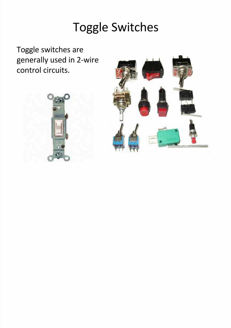
Toggle Switches
Toggle switches are
generally used in 2-wire
control circuits.
5/12/2018 Materi Bab 3 Switch n Relay(2) - slidepdf.com
http://slidepdf.com/reader/full/materi-bab-3-switch-n-relay2 4/34
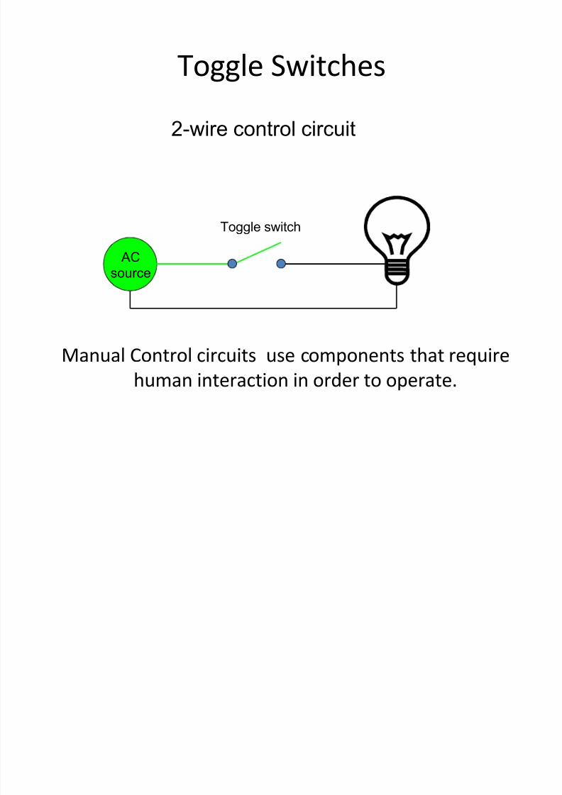
Toggle Switches
AC
source
Toggle switch
2-wire control circuit
Manual Control circuits use components that require
human interaction in order to operate.

5/12/2018 Materi Bab 3 Switch n Relay(2) - slidepdf.com
http://slidepdf.com/reader/full/materi-bab-3-switch-n-relay2 5/34
Toggle Switches
AC
source
Toggle switch
2-wire control circuit
SAFETY TIP!
2-wire control circuits should not be used on mechanical
loads due to restart after a loss of power occurs.

5/12/2018 Materi Bab 3 Switch n Relay(2) - slidepdf.com
http://slidepdf.com/reader/full/materi-bab-3-switch-n-relay2 6/34
5/12/2018 Materi Bab 3 Switch n Relay(2) - slidepdf.com
http://slidepdf.com/reader/full/materi-bab-3-switch-n-relay2 7/34
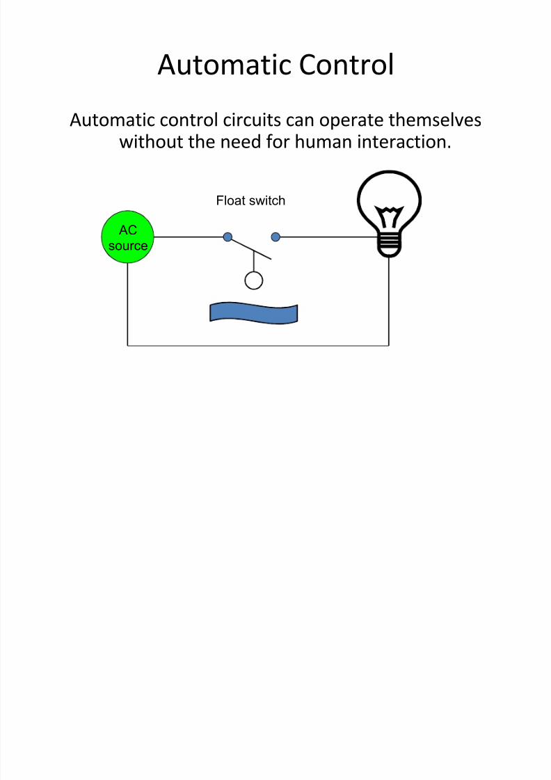
Automatic Control
Automatic control circuits can operate themselveswithout the need for human interaction.
AC
source
Float switch

5/12/2018 Materi Bab 3 Switch n Relay(2) - slidepdf.com
http://slidepdf.com/reader/full/materi-bab-3-switch-n-relay2 8/34
Automatic Control
Automatic control circuits can operate themselveswithout the need for human interaction.
AC
source
Float switch

5/12/2018 Materi Bab 3 Switch n Relay(2) - slidepdf.com
http://slidepdf.com/reader/full/materi-bab-3-switch-n-relay2 9/34
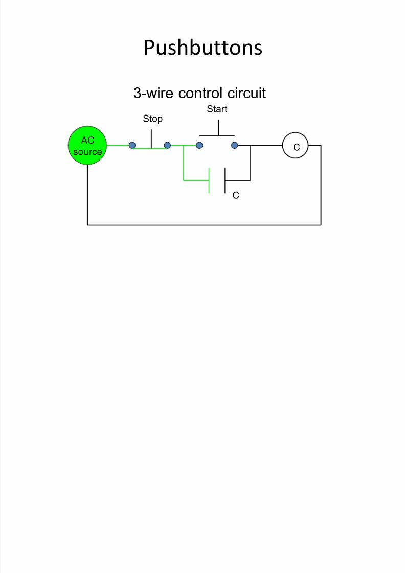
Pushbuttons
Pushbuttons are
generally used in 3-wire
control circuits because
of their momentaryoperation.
5/12/2018 Materi Bab 3 Switch n Relay(2) - slidepdf.com
http://slidepdf.com/reader/full/materi-bab-3-switch-n-relay2 10/34
Pushbuttons
ACsource C
C
StopStart
3-wire control circuit

5/12/2018 Materi Bab 3 Switch n Relay(2) - slidepdf.com
http://slidepdf.com/reader/full/materi-bab-3-switch-n-relay2 11/34
Pushbuttons
ACsource C
C
StopStart
3-wire control circuit

5/12/2018 Materi Bab 3 Switch n Relay(2) - slidepdf.com
http://slidepdf.com/reader/full/materi-bab-3-switch-n-relay2 12/34
Pushbuttons
ACsource C
C
StopStart
3-wire control circuit

5/12/2018 Materi Bab 3 Switch n Relay(2) - slidepdf.com
http://slidepdf.com/reader/full/materi-bab-3-switch-n-relay2 13/34
Pushbuttons
ACsource C
C
StopStart
3-wire control circuit

5/12/2018 Materi Bab 3 Switch n Relay(2) - slidepdf.com
http://slidepdf.com/reader/full/materi-bab-3-switch-n-relay2 14/34
Pushbuttons
ACsource C
C
StopStart
3-wire control circuit
5/12/2018 Materi Bab 3 Switch n Relay(2) - slidepdf.com
http://slidepdf.com/reader/full/materi-bab-3-switch-n-relay2 15/34
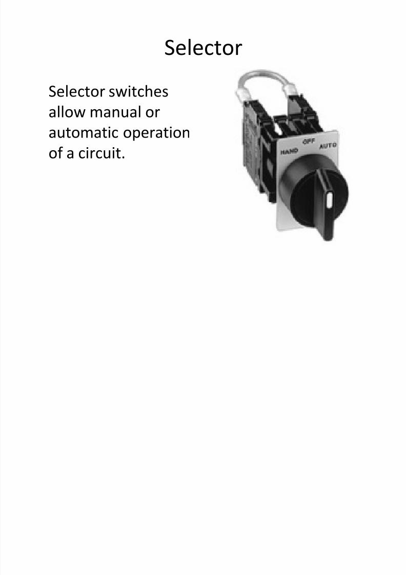
Selector
Selector switches
allow manual or
automatic operation
of a circuit.

5/12/2018 Materi Bab 3 Switch n Relay(2) - slidepdf.com
http://slidepdf.com/reader/full/materi-bab-3-switch-n-relay2 16/34
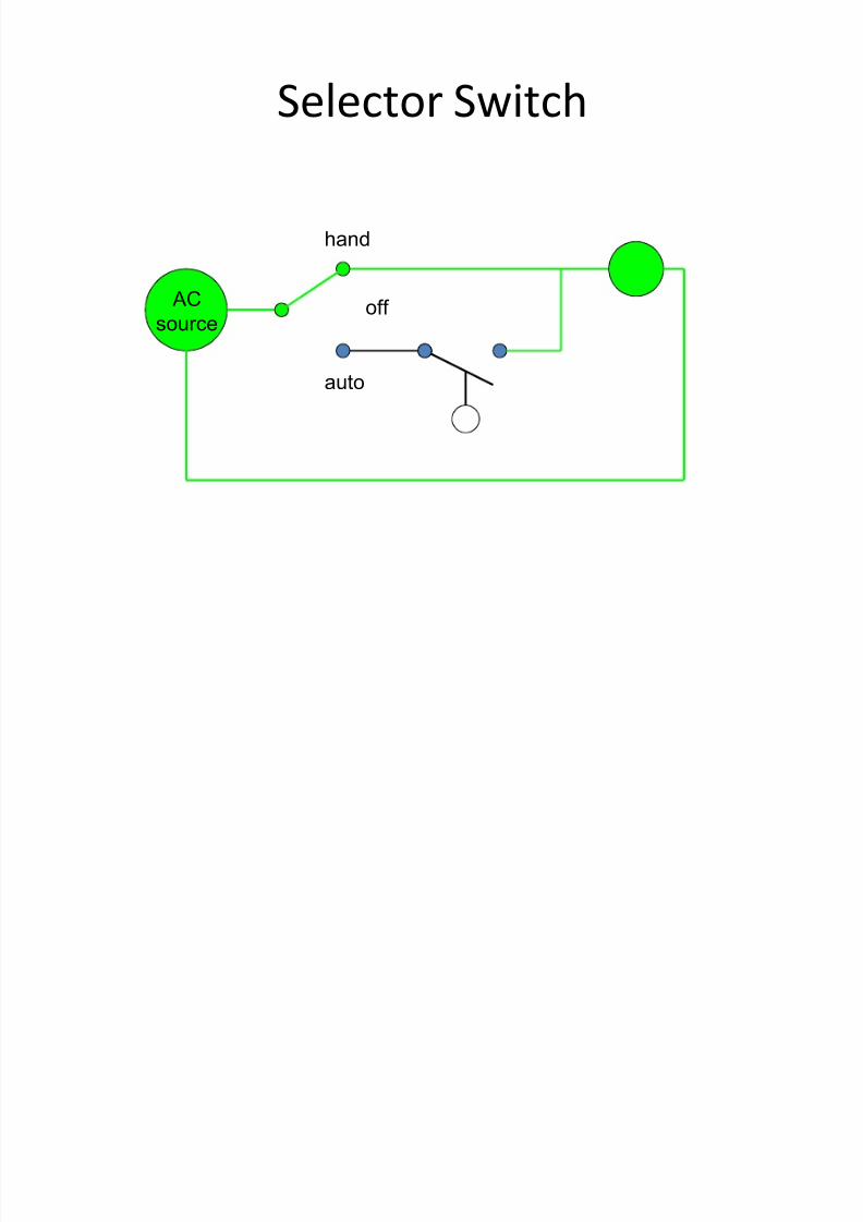
Selector Switch
ACsource
hand
off
auto
5/12/2018 Materi Bab 3 Switch n Relay(2) - slidepdf.com
http://slidepdf.com/reader/full/materi-bab-3-switch-n-relay2 17/34
Selector Switch
ACsource
hand
off
auto

5/12/2018 Materi Bab 3 Switch n Relay(2) - slidepdf.com
http://slidepdf.com/reader/full/materi-bab-3-switch-n-relay2 18/34
Selector Switch
ACsource
hand
off
auto

5/12/2018 Materi Bab 3 Switch n Relay(2) - slidepdf.com
http://slidepdf.com/reader/full/materi-bab-3-switch-n-relay2 19/34
Selector Switch
ACsource
hand
off
auto
5/12/2018 Materi Bab 3 Switch n Relay(2) - slidepdf.com
http://slidepdf.com/reader/full/materi-bab-3-switch-n-relay2 20/34
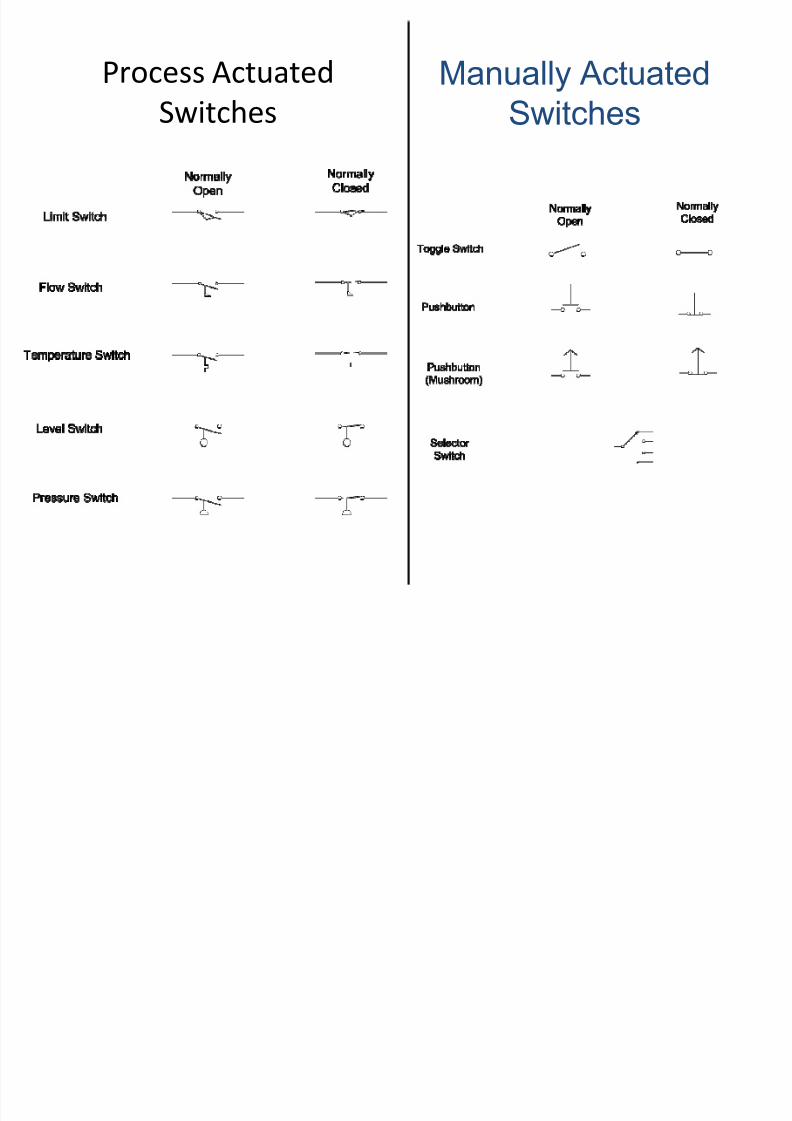
Process Actuated
Switches
Manually Actuated
Switches

5/12/2018 Materi Bab 3 Switch n Relay(2) - slidepdf.com
http://slidepdf.com/reader/full/materi-bab-3-switch-n-relay2 21/34
Relays A relay is a switch built with an electromagnet
controlled current
controlling current

5/12/2018 Materi Bab 3 Switch n Relay(2) - slidepdf.com
http://slidepdf.com/reader/full/materi-bab-3-switch-n-relay2 22/34

5/12/2018 Materi Bab 3 Switch n Relay(2) - slidepdf.com
http://slidepdf.com/reader/full/materi-bab-3-switch-n-relay2 23/34
Coils
When coils are energized, any contacts that are controlledby them change from their normal to energized state.
C
NO NC
Contacts can be Normally Open (NO) or Normally Closed (NC).
Contacts
Relays often used for motors.

5/12/2018 Materi Bab 3 Switch n Relay(2) - slidepdf.com
http://slidepdf.com/reader/full/materi-bab-3-switch-n-relay2 24/34
Coils
When coils are energized, any contacts that are controlledby them change from their normal to energized state.
C
NC NO
Contacts can be Normally Open (NO) or Normally Closed (NC).
Contacts
Relays often used for motors.

5/12/2018 Materi Bab 3 Switch n Relay(2) - slidepdf.com
http://slidepdf.com/reader/full/materi-bab-3-switch-n-relay2 25/34
CR
Relay coil
R1
R1 NOOutput contact
input
contact
coil
R1 NC
RELAYS
A switch that can be turned on
and off by electricity (instead of by
a person)
Uses magnetic properties of
materials and the magnetic forces
due to electric current flow
A switch whose operation is activated by an electromagnet is called a"relay"
IN
The switch is closed iff a High
voltage is applied to the input

5/12/2018 Materi Bab 3 Switch n Relay(2) - slidepdf.com
http://slidepdf.com/reader/full/materi-bab-3-switch-n-relay2 26/34
CR
Relay coil
R1
R1 NOOutput contact
input
contact
coil
R1 NC
RELAYS
A switch that can be turned on
and off by electricity (instead of by
a person)
Uses magnetic properties of
materials and the magnetic forces
due to electric current flow
A switch whose operation is activated by an electromagnet is called a"relay"
IN
The switch is closed iff a High
voltage is applied to the input

5/12/2018 Materi Bab 3 Switch n Relay(2) - slidepdf.com
http://slidepdf.com/reader/full/materi-bab-3-switch-n-relay2 27/34
Inside a Relay Magnetic force deflectsthe lever downward
when the coil is energizedSpring force restoresthe lever when thecoil is not energized
Connections to coil
Normally opencontact
Normally closedcontact
NO
NCCommon contact
Relay Actuated
Contacts
Timer On-Delay
Timer Off-Delay

5/12/2018 Materi Bab 3 Switch n Relay(2) - slidepdf.com
http://slidepdf.com/reader/full/materi-bab-3-switch-n-relay2 28/34
Inside a Relay Magnetic force deflectsthe lever downward
when the coil is energizedSpring force restoresthe lever when thecoil is not energized
Connections to coil
Normally opencontact
Normally closedcontact
NO
NCCommon contact
Relay Actuated
Contacts
Timer On-Delay
Timer Off-Delay

5/12/2018 Materi Bab 3 Switch n Relay(2) - slidepdf.com
http://slidepdf.com/reader/full/materi-bab-3-switch-n-relay2 29/34

5/12/2018 Materi Bab 3 Switch n Relay(2) - slidepdf.com
http://slidepdf.com/reader/full/materi-bab-3-switch-n-relay2 30/34
A simple relay
circuit
In a digital circuit thevoltages can onlytake on one of twodiscrete values: High
and Low
Vcc
G ND
G ND
Switch
Bulb
OUT

5/12/2018 Materi Bab 3 Switch n Relay(2) - slidepdf.com
http://slidepdf.com/reader/full/materi-bab-3-switch-n-relay2 31/34
The symbols used in a ladder logic diagram are as shown:
The ladder logic diagram is used to represent the logic in a PLC
control program widely in industry. The ladder logic diagram
makes use of representations similar to electrical circuits in which
a series connection represents a logical AND, and a parallelconnection represents a logical OR.
Input Output
Set-Reset Ladder Diagram
AND
OR
NOT

5/12/2018 Materi Bab 3 Switch n Relay(2) - slidepdf.com
http://slidepdf.com/reader/full/materi-bab-3-switch-n-relay2 32/34
Wiring diagram
Ladder diagram for the circuit
AN EXAMPLE OF
RELAY LOGIC
For a process control, it isdesired to have the processstart (by turning on a motor)five seconds after a part
touched a limit switch.
The process is terminatedautomatically when thefinished part touches asecond limit switch.
An emergency switch willstop the process any timewhen it is pushed.

5/12/2018 Materi Bab 3 Switch n Relay(2) - slidepdf.com
http://slidepdf.com/reader/full/materi-bab-3-switch-n-relay2 33/34
Jenis-jenis Limit Switch

5/12/2018 Materi Bab 3 Switch n Relay(2) - slidepdf.com
http://slidepdf.com/reader/full/materi-bab-3-switch-n-relay2 34/34