MasterCAM for Dresser Valet - Central Bucks School ... · MasterCAM for Dresser Valet ... To Verify...
20
MasterCAM for Dresser Valet Check to make sure the nethasp is working/turned on to network. Go to ALL APPs/Mastercam x8/nethasp
-
Upload
trinhthuan -
Category
Documents
-
view
214 -
download
0
Transcript of MasterCAM for Dresser Valet - Central Bucks School ... · MasterCAM for Dresser Valet ... To Verify...

MasterCAM for Dresser Valet
Check to make sure the nethasp is working/turned on to network.
Go to ALL APPs/Mastercam x8/nethasp

Open the MasterCAM application, it should look something like below.
After the
computer “reads”
the nethasp,
these programs
should show up.
If not ask your
instructor.

First thing is to figure out what you are making….Using the measurements from your plans or
your adjusted measurements from your plans, you will draw your geometry (geometry is a
generic term for lines, arcs, etc. in a computer drawing program). Personally I just draw on the
piece of wood that is going to be cut and plot the points needed to draw the geometry. This
geometry must be drawn in the 1st quadrant of the coordinate system, so positive x and y. The
placement of the geometry matters since we will later be cutting out the part using the CNC
Router. The CNC Router uses the coordinates from where you draw the geometry.
F9 will display the x/y axis such as:
To start a project, we need to set our specific CNC router and set up the stock sizes. MasterCAM can
write NC code for different manufacturers of CNC equipment. Our router is a Forest Scientific Velosity 3
axis mill. MasterCAM will write the correct type of code as long as we pick the correct machine
definition. This is a critical first step, without the machine definition, the CNC router will crash….litterly
the tool bit will dive into the table top. Your instructor will help you load the machine definition when
you go to the cnc router, for the time being set the machine definition to default mill. Goto Machine
Type/Mill/Default.
Draw starting at
the origin (0,0)

The result: there should be one machine group that says “Properties Default Mill,” if there is other
Machine Groups, right-click and delete them.
Stock Setup
The Toolpaths Operations Manager is
the tool palette that is docked on the
left of the screen. This displays all the
specific information about the tool
paths (what the CNC router will cut).
Expand the properties tab in the
operations manager. Then click on
stock setup.

After you click ok in the stock setup, you should see a red dashed rectangle that represents your stock.
Zoom in or out so that you see the whole piece, like below.
Setup the stock:
Enter the measurements for your
piece, I’m putting in 10.25 (y),
15.25 (x), .75(z) for my
measurements for the project. I’m
not including the extra stock for
the screws to hold it down to the
router.
Set the stock origin by clicking on
this corner.
Check “Display”
Click the Green Check Mark (OK)
Leave these
x,y,z’s at 0
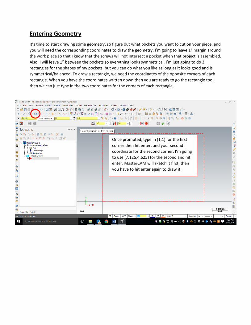
Entering Geometry
It’s time to start drawing some geometry, so figure out what pockets you want to cut on your piece, and
you will need the corresponding coordinates to draw the geometry. I’m going to leave 1” margin around
the work piece so that I know that the screws will not intersect a pocket when that project is assembled.
Also, I will leave 1” between the pockets so everything looks symmetrical. I’m just going to do 3
rectangles for the shapes of my pockets, but you can do what you like as long as it looks good and is
symmetrical/balanced. To draw a rectangle, we need the coordinates of the opposite corners of each
rectangle. When you have the coordinates written down then you are ready to go the rectangle tool,
then we can just type in the two coordinates for the corners of each rectangle.
Once prompted, type in (1,1) for the first
corner then hit enter, and your second
coordinate for the second corner, I’m going
to use (7.125,4.625) for the second and hit
enter. MasterCAM will sketch it first, then
you have to hit enter again to draw it.
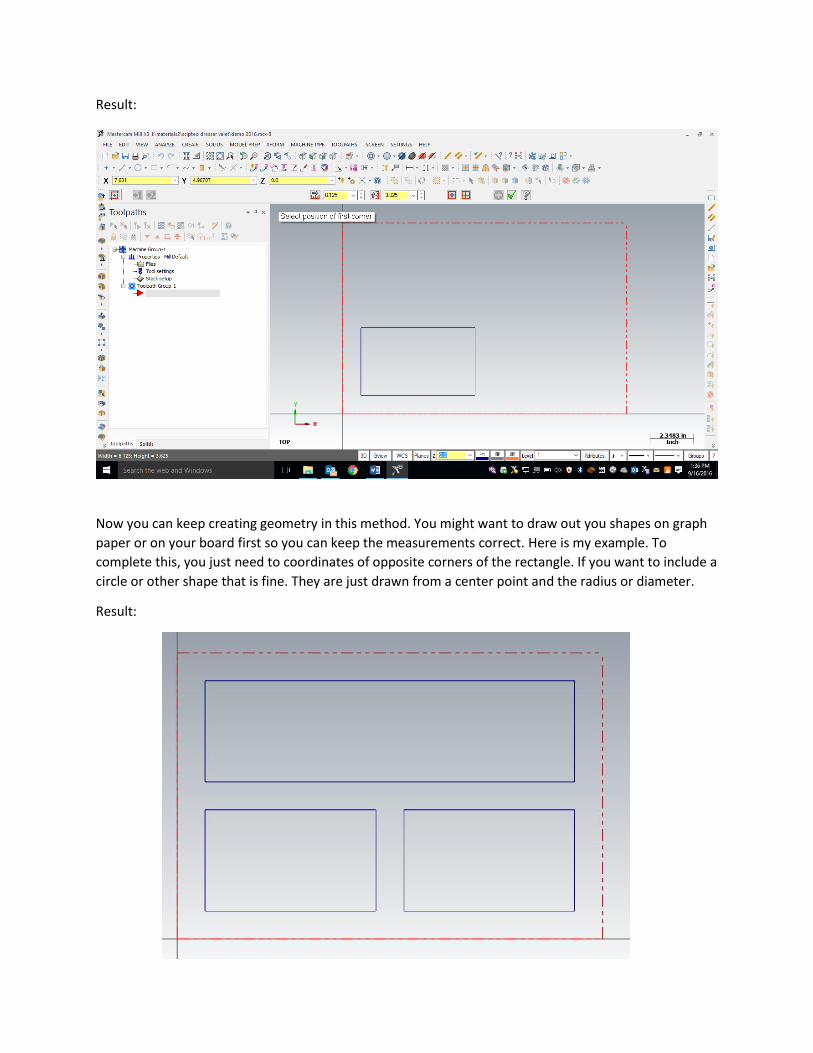
Result:
Now you can keep creating geometry in this method. You might want to draw out you shapes on graph
paper or on your board first so you can keep the measurements correct. Here is my example. To
complete this, you just need to coordinates of opposite corners of the rectangle. If you want to include a
circle or other shape that is fine. They are just drawn from a center point and the radius or diameter.
Result:

Toolpaths: For 2D geometry such as we have, there are 2 main types of tool paths. The first one is a
contour, and the second a pocket. In a contour toolpath, the tool bit will follow a path. The path
can be one piece of geometry or multiple pieces of geometry linked together end to end. When
the geometry is selected you must either pick the single option or the chaining option (multiple
objects laid out end to end) before you select the geometry. We are going to complete pocket
toolpaths. A pocket toolpath will make a cavity inside the selected geometry. We should be
able to use one pocket toolpath and pick all the geometry to complete the cut correctly. When
we select the geometry, we will use the chaining option, since the rectangles are really made
from four lines each.
To start the toolpaths, go to Toolpaths/Pocket.
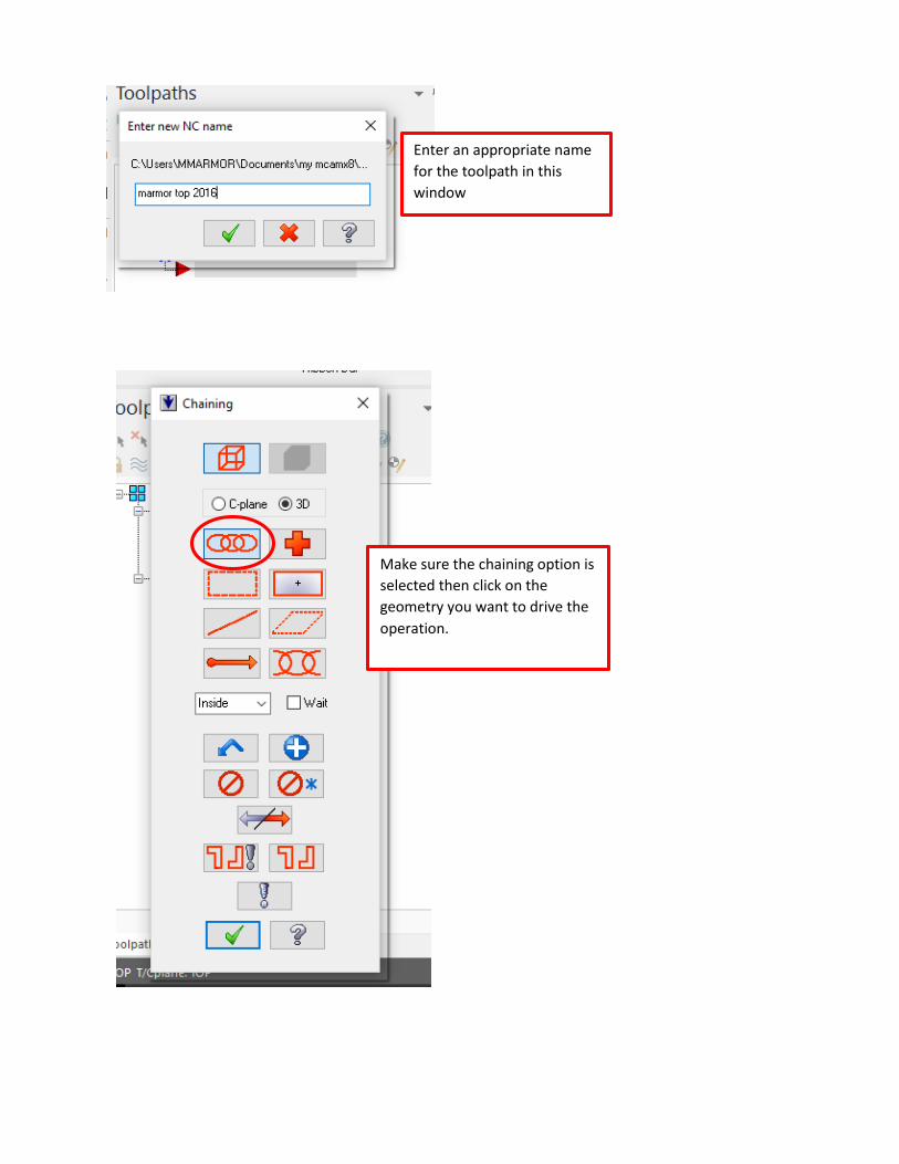
Enter an appropriate name
for the toolpath in this
window
Make sure the chaining option is
selected then click on the
geometry you want to drive the
operation.

Click ok, to end our selection.
Click on the 3 chains (the 3
rectangles) one click should
select all the sides of the
rectangles. After the selection
your screen should look like this,
the green arrow should appear
each time you click on a new
chain. It may disappear then.
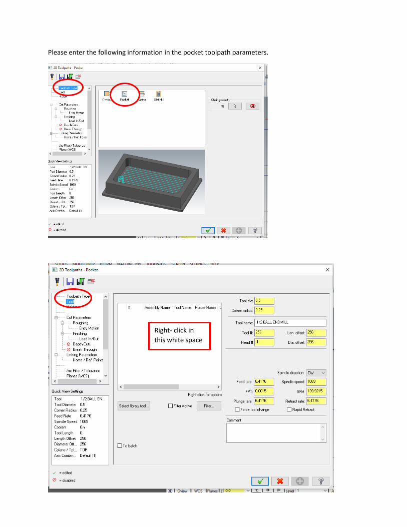
Please enter the following information in the pocket toolpath parameters.
Right- click in
this white space

You may need to use a different
tool depending on what you are
doing and what tool is available.
Ask your instructor.
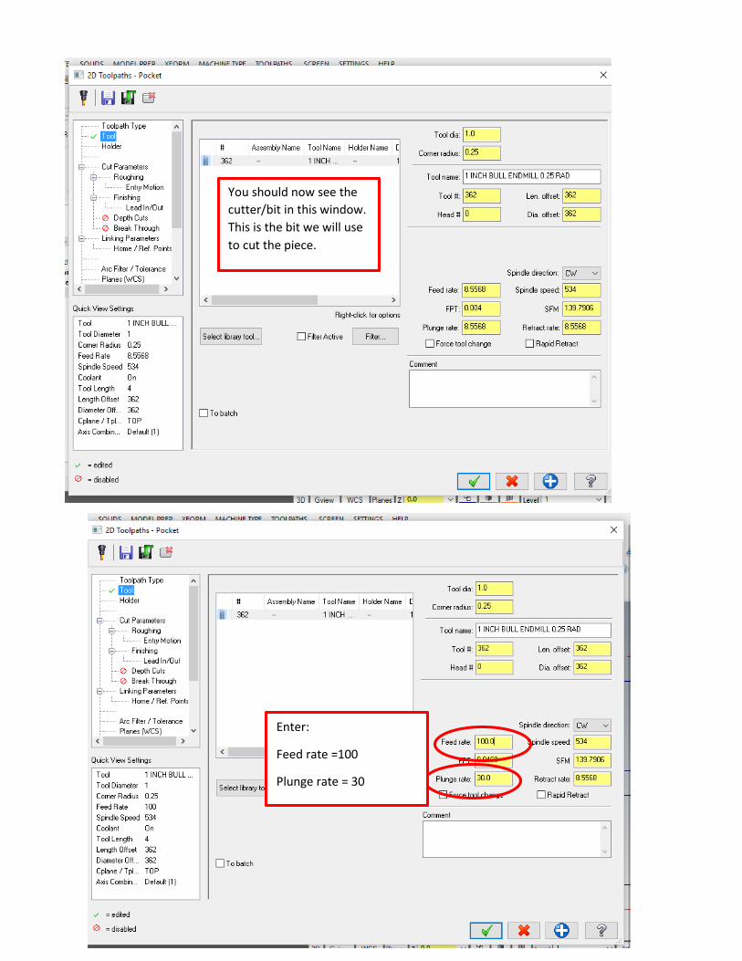
You should now see the
cutter/bit in this window.
This is the bit we will use
to cut the piece.
Enter:
Feed rate =100
Plunge rate = 30

Enter 0 for both “stock to
leave” fields.
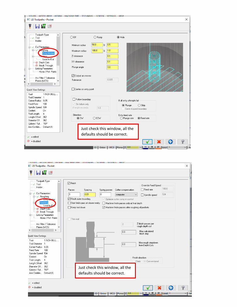
Just check this window, all the
defaults should be correct.
Just check this window, all the
defaults should be correct.


To set the depth of the cut, please enter the below values. In the Linking Parameters tab. Notice that all
the values are “Absolute” and the depth is a -.5.
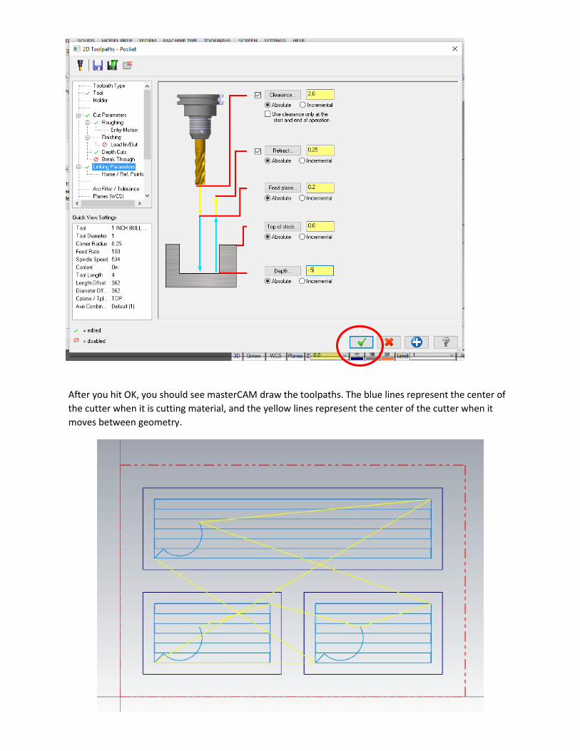
After you hit OK, you should see masterCAM draw the toolpaths. The blue lines represent the center of
the cutter when it is cutting material, and the yellow lines represent the center of the cutter when it
moves between geometry.

To Verify your toolpath, go to an isometric view, zoom in/out, and pan the drawing so you see
something such as below:
Next click Verify

This will open up in a new window titled “MasterCAM Simulator”, and you can push the play button at
the bottom of the window. It should see your part cut out virtually. Please show your instructor.