Master User Guide - CCTV Camera...
36
Issue 8 Premier 412/816/832 Master User Guide
-
Upload
nguyenduong -
Category
Documents
-
view
225 -
download
4
Transcript of Master User Guide - CCTV Camera...

Issue 8
Premier 412/816/832Master User Guide

Contents
1. About the Alarm System ............................ 3 Introduction ...................................................................... 3
Control Panel Standard – Features for False Alarm Reduction. ........................................................................ 3
Part codes for UL/C-UL Listed Installations ................... 3 Enclosures ....................................................................... 3 Circuit Board .................................................................... 3 Keypads ........................................................................... 3 Expanders ........................................................................ 3 Other Devices .................................................................. 3 About this Manual ............................................................ 4 Fire Detection ................................................................... 4 Monitoring ........................................................................ 4 Zones and Partitions ........................................................ 4 Access Codes .................................................................. 4
Remote Keypads .............................................................. 5 Keypad Types .................................................................. 5 Keypad Layouts ............................................................... 5 Function Keys .................................................................. 6 Emergency Keys .............................................................. 6
2. Operating the Alarm System ..................... 7 Introduction ...................................................................... 7
Access Codes .................................................................. 7 Arming & Disarming the Alarm System ........................... 7
Checking if the System is Ready to Arm ........................ 7 Away Arming .................................................................... 7 Stay Arming ..................................................................... 7 Cancelling the Arming Process ....................................... 8 Disarming During Entry ................................................... 8 Disarming when not in Entry ........................................... 8 Disarming after an Alarm ................................................. 9 Auto Stay Arming ............................................................. 9 Changing between Delayed and Instant Stay ................ 9
Arming and Disarming Partitions .................................. 10 Away Arming Partitions ................................................. 10 Stay Arming Partitions ................................................... 10 Disarming Partitions ...................................................... 10 Changing to another Partition ....................................... 11
Bypassing Zones ............................................................ 11 Manually Bypassing Zones ........................................... 11
2 INS141
Unbypassing Zones....................................................... 11 Group Bypass ................................................................ 11 Quick Bypass and Arm .................................................. 12
3. User Functions Menu ............................... 13 Reset Alarms .................................................................. 13 Last Alarm Log ............................................................... 13 Service Faults ................................................................. 13
Acknowledging a New Service Fault ............................ 13 View Service Faults ........................................................ 13
Anti-code Reset .............................................................. 14 Toggle Chime On and Off .............................................. 14 Change User Code ......................................................... 15 View Log (LCD Only) ...................................................... 15 Abort Communications .................................................. 15
4. System Program Menus ........................... 16 Programming Text (LCD Only) ...................................... 17
Programming Users ....................................................... 18 Program User .............................................. 19 User Options 1 ............................................. 20 User Options 2 ............................................. 20 User Options 3 ............................................. 20
User Text (LCD Only) ................................... 21 Program Standard Users ............................. 21
System Tests & Utilities ................................................. 22 Walk Test .................................................... 23 Test Speakers Outputs ............................. 23 &Send Test Call .............................................. 23 Enable Remote Engineer Access ................ 23 /Start Call Back .............................................. 23 Program Time ............................................... 23 Program Date ............................................... 23 Program Banner Text (LCD only) ................. 23 Print 100 Events ............................................ 23 Exit Program Mode ....................................... 23
5. Fire Safety & Maintenance ....................... 24 Fire Safety ....................................................................... 24
Fire Alarm Operation ...................................................... 24 Household Fire Safety Audit .......................................... 24 Fire Escape Planning ..................................................... 24
Maintenance ................................................................... 25 Glossary .......................................................................... 25 Basic fire escape planning ............................................. 26
Putting your plan to the test ........................................... 26
6. FCC Statements ........................................ 27 Operation is subject to the following conditions. .......... 28
Canadian Emissions Statement ..................................... 28 Automatic Diallers .......................................................... 29
7. Installation Records .................................. 30 Control Panel .................................................................. 30 Keypads .......................................................................... 30 Timers ............................................................................. 30 Users ............................................................................... 30 Zones .............................................................................. 31
8. Annex A ...................................................... 32 Table 1 ANSI/SIA CP-01-2007 Requirements Section 4.7/Annex A/ 4.6.1 .......................................................... 32
Minimum system requirements for Classification in accordance with ANSI/SIA CP-01-2007 ......................... 34 Notes ............................................................................... 35
DO NOT REMOVE COVER
MAINS VOLTAGES INSIDE
No user serviceable parts, servicing by qualified personnel only.
Premier 412/816/832 Master User Manual
1. About the Alarm System
Introduction Your alarm system consists of a control panel, one or more keypads and various detectors and sensors. The control panel will normally be mounted out of sight in a utility room or basement etc. The control panel houses the system’s electronics and stand-by battery. There is normally no reason for anyone except an installer or service person to have access to the control panel.
The remote keypad is used to send commands to the system and to display the current system status via the various coloured lights (LED’s). The keypad also provides audible feedback each time a key is pressed. Each keypad will be mounted in convenient locations inside the protected premises, near designated points of entry/exit.
Read this manual carefully and have your installer instruct you on your system’s operation. Become familiar with the features that have been implemented on your system. All users of this system should be equally instructed in its use.
Control Panel Standard – Features for False Alarm Reduction.
For details of the requirements to comply with ANSI/SIA CP-01-2007 please see Table 1 in Annex A page 29
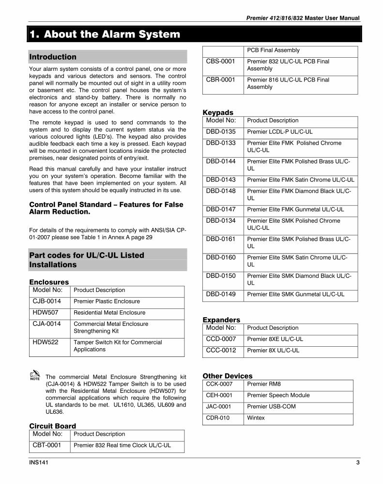
Part codes for UL/C-UL Listed Installations
Enclosures Model No: Product Description
CJB-0014 Premier Plastic Enclosure
HDW507 Residential Metal Enclosure
CJA-0014 Commercial Metal Enclosure Strengthening Kit
HDW522 Tamper Switch Kit for Commercial Applications
The commercial Metal Enclosure Strengthening kit (CJA-0014) & HDW522 Tamper Switch is to be used with the Residential Metal Enclosure (HDW507) for commercial applications which require the following UL standards to be met. UL1610, UL365, UL609 and UL636.
Circuit Board Model No: Product Description
CBT-0001 Premier 832 Real time Clock UL/C-UL
PCB Final Assembly
CBS-0001 Premier 832 UL/C-UL PCB Final Assembly
CBR-0001 Premier 816 UL/C-UL PCB Final Assembly
Keypads Model No: Product Description
DBD-0135 Premier LCDL-P UL/C-UL
DBD-0133 Premier Elite FMK Polished Chrome UL/C-UL
DBD-0144 Premier Elite FMK Polished Brass UL/C-UL
DBD-0143 Premier Elite FMK Satin Chrome UL/C-UL
DBD-0148 Premier Elite FMK Diamond Black UL/C-UL
DBD-0147 Premier Elite FMK Gunmetal UL/C-UL
DBD-0134 Premier Elite SMK Polished Chrome UL/C-UL
DBD-0161 Premier Elite SMK Polished Brass UL/C-UL
DBD-0160 Premier Elite SMK Satin Chrome UL/C-UL
DBD-0150 Premier Elite SMK Diamond Black UL/C-UL
DBD-0149 Premier Elite SMK Gunmetal UL/C-UL
Expanders Model No: Product Description
CCD-0007 Premier 8XE UL/C-UL
CCC-0012 Premier 8X UL/C-UL
Other Devices CCK-0007 Premier RM8
CEH-0001 Premier Speech Module
JAC-0001 Premier USB-COM
CDR-010 Wintex
INS141 3
Premier 412/816/832 Master User Manual
About this Manual This manual is a thorough explanation of all system functions, including troubleshooting and programming Access codes in addition to performing basic system functions. Most users of the system will not need to know all of this information. The section of this manual, titled “Operating your Alarm System” explains general system concepts and instructs the user on how to arm and disarm the system and bypass zones. The remaining sections of the manual are reserved for more detailed system information.
Fire Detection This equipment is capable of monitoring fire detection devices such as smoke detectors and providing a warning alarm if a fire condition is detected. Good fire detection depends on having adequate numbers of fire detectors placed in appropriate locations. This equipment should be installed in accordance with the relevant local authority fire regulations. Carefully review the “Fire Escape Planning” guidelines in this manual.
Your installer must enable the fire detection feature of this equipment before it will work.
Monitoring This system is capable of transmitting alarms, troubles and emergency information over telephone lines to an alarm monitoring station. If you inadvertently initiate an alarm, immediately call the Alarm Receiving Centre (ARC) to prevent an unnecessary response.
Your installer must enable the monitoring function before it will work.
Zones and Partitions Your installer has divided the protected premises into zones and partitions. A zone is an area of protection that has one or more detection sensors connected to it (motion detectors, glass-break detectors, door contacts or shock sensors). A single zone might be a room, a hallway or a door or window. Two or more of these zones will be linked together by the control panel to form a partition.
A partition is an area of the protected premises. A partition can be armed and disarmed independently from other partitions. All of the partitions together form the entire alarm system. If your alarm system is not divided into partitions then all devices will be assigned to Partition 1.
Some zones may belong to more than one partition, such as points of entry/exit and hallways. These are called Global Zones because they are not assigned to a single partition.
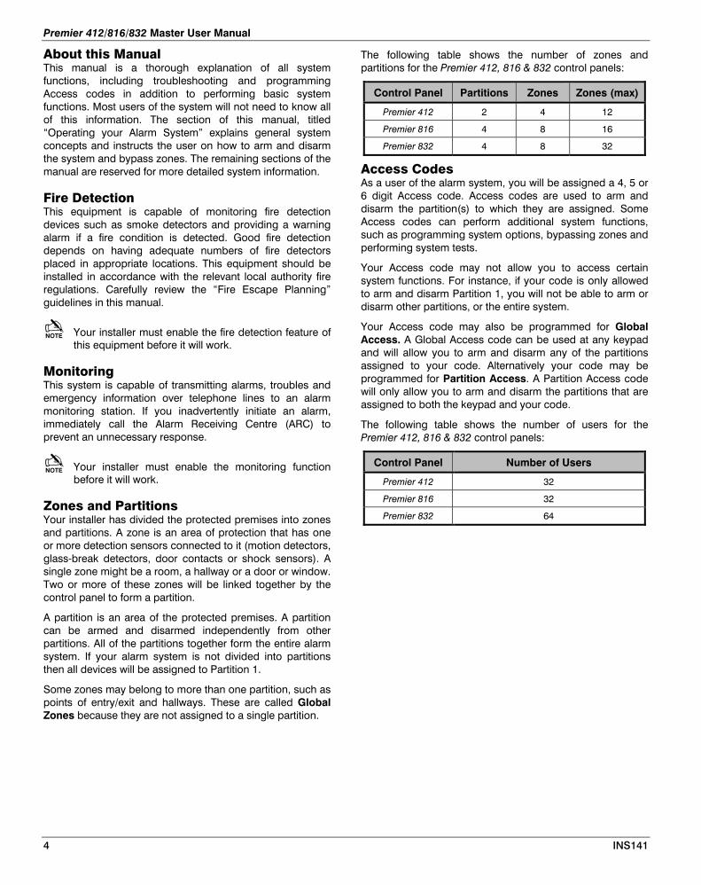
The following table shows the number of zones and partitions for the Premier 412, 816 & 832 control panels:
Control Panel Partitions Zones Zones (max)
Premier 412 2 4 12
Premier 816 4 8 16
Premier 832 4 8 32
Access Codes As a user of the alarm system, you will be assigned a 4, 5 or 6 digit Access code. Access codes are used to arm and disarm the partition(s) to which they are assigned. Some Access codes can perform additional system functions, such as programming system options, bypassing zones and performing system tests.
Your Access code may not allow you to access certain system functions. For instance, if your code is only allowed to arm and disarm Partition 1, you will not be able to arm or disarm other partitions, or the entire system.
Your Access code may also be programmed for Global Access. A Global Access code can be used at any keypad and will allow you to arm and disarm any of the partitions assigned to your code. Alternatively your code may be programmed for Partition Access. A Partition Access code will only allow you to arm and disarm the partitions that are assigned to both the keypad and your code.
The following table shows the number of users for the Premier 412, 816 & 832 control panels:
Control Panel Number of Users
Premier 412 32
Premier 816 32
Premier 832 64
4 INS141
Premier 412/816/832 Master User Manual
Remote Keypads
One or more remote keypads will be installed throughout the protected premises, usually one at each entry/exit door. Each remote keypad is normally assigned to the partition that it is going to control. A keypad can be assigned to more than one partition, if required (global keypad).
Keypad Types The following keypad types are available:
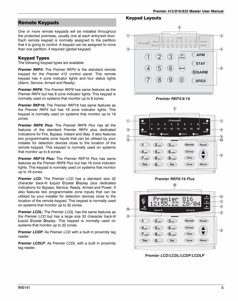
Premier RKP4: The Premier RKP4 is the standard remote keypad for the Premier 412 control panel. This remote keypad has 4 zone indicator lights and four status lights (Alarm, Service, Armed and Ready).
Premier RKP8: The Premier RKP8 has same features as the Premier RKP4 but has 8 zone indicator lights. This keypad is normally used on systems that monitor up to 8 zones.
Premier RKP16: The Premier RKP16 has same features as the Premier RKP4 but has 16 zone indicator lights. This keypad is normally used on systems that monitor up to 16 zones.
Premier RKP8 Plus: The Premier RKP8 Plus has all the features of the standard Premier RKP4 plus dedicated indications for Fire, Bypass, Instant and Stay. It also features two programmable zone inputs that can be utilised by your installer for detection devices close to the location of the remote keypad. This keypad is normally used on systems that monitor up to 8 zones.
Premier RKP16 Plus: The Premier RKP16 Plus has same features as the Premier RKP8 Plus but has 16 zone indicator lights. This keypad is normally used on systems that monitor up to 16 zones.
Premier LCD: The Premier LCD has a standard size 32 character back-lit Liquid Crystal Display plus dedicated indications for Bypass, Service, Ready, Armed and Power. It also features two programmable zone inputs that can be utilised by your installer for detection devices close to the location of the remote keypad. This keypad is normally used on systems that monitor up to 32 zones.
Premier LCDL: The Premier LCDL has the same features as the Premier LCD but has a large size 32 character back-lit Liquid Crystal Display. This keypad is normally used on systems that monitor up to 32 zones.
Premier LCDP: As Premier LCD with a built in proximity tag reader.
Premier LCDLP: As Premier LCDL with a built in proximity tag reader.
Keypad Layouts
Alarm Armed
Service Ready
StayFire
1 2 3 4 5 6 7 8
9 10 11 12 13 14 15 16
Bypass Instant
4 5 6
1 2 3
7 8 9 0
Armed
Zones8
16
7
15
6
14
5
13
4
12
3
11
2
10
1
9
Ready
Alarm
Service
ARM
STAY
DISARM
BYPASS
MENU
AREA
Premier RKP4/8/16
Premier RKP8/16 Plus
�
�
�
�
�
�
�
�
�
�
�
�
�
4 ghi
2 abc 3 def
7 pqrs
Area
5 jkl
8 tuv
0
6 mno
9 wxyz
1
Yes
Stay
Chime
Bypass Reset
MenuNo
Bypass Service
Power
Armed
Ready
����������� ���������
4 ghi
2 abc 3 def
7 pqrs
Area
5 jkl
8 tuv
0
6 mno
9 wxyz
1
Yes
Stay
Chime
Bypass Reset
MenuNo
Premier LCD/LCDL/LCDP/LCDLP
�
�
�
�
�
�
INS141 5
Premier 412/816/832 Master User Manual
Function Keys - Alarm Light: If an alarm has occurred whilst thepartition/system was armed the Alarm light will illuminate.
The alarm partition/system cannot be Armed until astanding Alarm has been acknowledged/reset (see“Acknowledging an Alarm” on page 13).
- Service Light: The Service light will flash when a new faultoccurs and will change to on steady when the fault hasbeen acknowledged. When the system is free of all faultsthe Service light will be off.
The alarm system cannot be armed until the new faults have been acknowledged (see “Service Faults” on page13).
- Armed Light: The Armed light indicates the armed status ofthe partition/system. The Armed light is on when thepartitions assigned to the keypad are armed. When the Armed light is off the partitions are disarmed. The Armedlight will flash as follows:
Partition in Exit: Slow flash (1 second on, 1 second off).
Partition is Delayed Stay Armed: Slow flash (1 second on,1 second off).
Partition is Instant Stay Armed: Fast flash (200milliseconds on, 200 milliseconds off).
- Ready Light: If the Ready light is on the partition/system isready for arming. If the Ready light is off, one or morezones within the partition/system are violated, check therelevant zones as indicated on the keypads. If the Readylight is flashing, one or more zones are bypassed or areviolated and force-armable.
- Zone Lights: The zone lights indicate the status of eachalarm zone within the partition. When a zone is violated orin trouble the relevant zone light will illuminate. When azone is secure the relevant zone light will be off.
A keypad can be programmed to blank its display after aperiod of time. An Access code may be required to re-enable the display. Otherwise simply press any key.
Zone display is always enabled when the alarm system is in alarm.
- Function Keys: See “Function Keys”.
- Fire: if the Fire light is on with no zone indicatorsilluminated, then a fire alarm has occurred from one of the2-wire smoke sensors. If there is an accompanied zoneindication, the fire alarm has occurred from the smokesensor on the indicated zone.
- Bypass: If the Bypass light is on, one or more zones havebeen manually bypassed, (see “Manually BypassingZones” on page 11).
- Stay: If the Stay light is on, the partition/system is in thestay armed mode. The Armed light will also be flashing.
- Instant: If the Instant light is on, the partition/system is inthe stay armed mode and the delayed zones (front dooretc) are instant. The Armed light will also be flashingrapidly.
- Power Light: The power light is on steady when mainssupply is present and flashes when the system is runningon battery (mains fail).
- LCD Display: 16 character Liquid Crystal Display (LCD).
- Proximity Tag Reader: On Premier LCDP and LCDLP only.
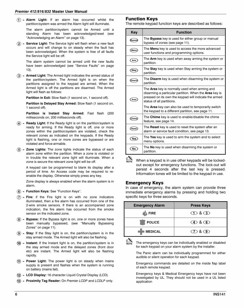
The remote keypad function keys are described as follows:
Key Function
The Bypass key is used for either group or manual bypass of zones (see page 11).
The Menu key is used to access the more advanced user functions and programming options.
The Arm key is used when away arming the system or partition.
The Stay key is used when Stay arming the system or partition.
The Disarm key is used when disarming the system or partition.
The Area key is normally used when arming and disarming a particular partition. When the Area key is pressed on its own the keypad will indicate the armed status of all partitions.
The Area key can also be used to temporarily switch the keypad to a different partition, see page 11.
The Chime key is used to enable/disable the chime feature, see page 14.
The Reset key is used to reset the system after an alarm or service fault condition, see page 13.
The Yes key is used to arm the system and to select menu options.
The No key is used when disarming the system or partition.
When a keypad is in use other keypads will be locked-out except for emergency functions. The lock-out will persist 4 seconds after the last key is pressed. Information tones will be limited to the keypad in use.
Emergency Keys In case of emergency, the alarm system can provide three immediate emergency alarms by pressing and holding two specific keys for three seconds.
Emergency Alarm Press Keys
&
&
&
The emergency keys can be individually enabled or disabled for each keypad on your alarm system by the installer.
The Panic alarm can be individually programmed for either audible or silent operation for each keypad.
Emergency commands are detailed on the inside flap label of each remote keypad.
Emergency keys & Medical Emergency keys have not been investigated by UL. They should not be used in a UL listed application
6 INS141
Premier 412/816/832 Master User Manual
2. Operating the Alarm System
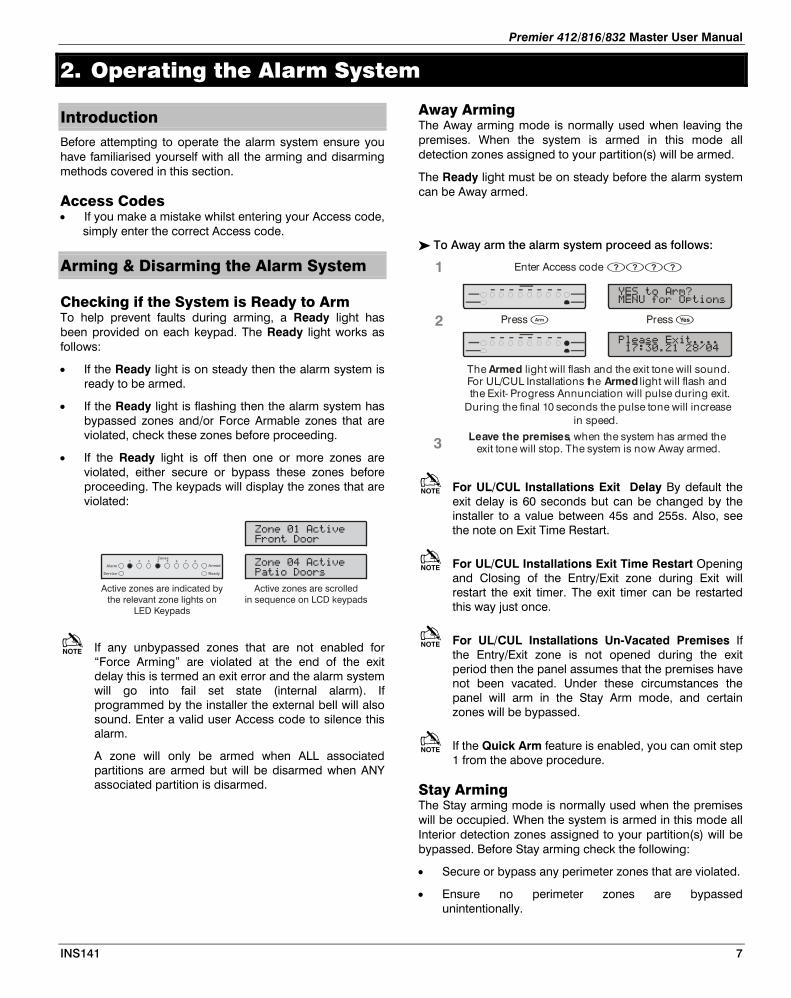
Introduction Before attempting to operate the alarm system ensure you have familiarised yourself with all the arming and disarming methods covered in this section.
Access Codes • If you make a mistake whilst entering your Access code,
simply enter the correct Access code.
Arming & Disarming the Alarm System
Checking if the System is Ready to Arm To help prevent faults during arming, a Ready light has been provided on each keypad. The Ready light works as follows:
• If the Ready light is on steady then the alarm system is ready to be armed.
• If the Ready light is flashing then the alarm system has bypassed zones and/or Force Armable zones that are violated, check these zones before proceeding.
• If the Ready light is off then one or more zones are violated, either secure or bypass these zones before proceeding. The keypads will display the zones that are violated:
��������������
�����������Armed
Zones87654321
Ready
Alarm
Service
�������������
����������
Active zones are scrolledin sequence on LCD keypads
Active zones are indicated bythe relevant zone lights on
LED Keypads
If any unbypassed zones that are not enabled for “Force Arming” are violated at the end of the exit delay this is termed an exit error and the alarm system will go into fail set state (internal alarm). If programmed by the installer the external bell will also sound. Enter a valid user Access code to silence this alarm.
A zone will only be armed when ALL associated partitions are armed but will be disarmed when ANY associated partition is disarmed.
Away Arming The Away arming mode is normally used when leaving the premises. When the system is armed in this mode all detection zones assigned to your partition(s) will be armed.
The Ready light must be on steady before the alarm system can be Away armed.
To Away arm the alarm system proceed as follows:
The light will flash and the exit tone will sound. For UL/CUL Installations t
Armedhe light will flash and
the Exit- Progress Annunciation will pulse during exit. During the final 10 seconds the pulse tone will increase
in speed.
Armed
Press
Enter Access code
Press
1
2
3 Leave the premises, when the system has armed the exit tone will stop. The system is now Away armed.
For UL/CUL Installations Exit Delay By default the exit delay is 60 seconds but can be changed by the installer to a value between 45s and 255s. Also, see the note on Exit Time Restart.
For UL/CUL Installations Exit Time Restart Opening and Closing of the Entry/Exit zone during Exit will restart the exit timer. The exit timer can be restarted this way just once.
For UL/CUL Installations Un-Vacated Premises If the Entry/Exit zone is not opened during the exit period then the panel assumes that the premises have not been vacated. Under these circumstances the panel will arm in the Stay Arm mode, and certain zones will be bypassed.
If the Quick Arm feature is enabled, you can omit step 1 from the above procedure.
Stay Arming The Stay arming mode is normally used when the premises will be occupied. When the system is armed in this mode all Interior detection zones assigned to your partition(s) will be bypassed. Before Stay arming check the following:
• Secure or bypass any perimeter zones that are violated.
• Ensure no perimeter zones are bypassed unintentionally.
INS141 7

Premier 412/816/832 Master User Manual
Ensure no perimeter Force Armable zones are violated unintentionally.
To Stay arm the alarm system proceed as follows:
���������
������������
� !�������"
# $%�&���'(�����
The alarm system will arm immediately and thelight will flash.
Armed
Press �
Enter Access code ����
Armed
Zones87654321
Ready
Alarm
Service
1
2
3
Armed
Zones87654321
Ready
Alarm
Service
The system is now Stay armed.
If the Quick Arm feature is enabled, you can omit step 1 from the above procedure.
If the system is fitted with a Premier RKP8/16 Plus then the Stay light will also illuminate when the system is Stay armed.
Cancelling the Arming Process
To cancel the arming process during the exit delay:
���������
������������Armed
Zones87654321
Ready
Alarm
Service
# $%�&���'(�����
$'����������"
Arming has been cancelled and the alarm system isnow disarmed.
Press �
Enter Access code ����
Armed
Zones87654321
Ready
Alarm
Service
1
2
3
Press �
If the system only has one partition you will not have to perform step 2.
Disarming During Entry
To disarm the alarm system during entry, proceed as follows:
The entry tone will stop and the light will turn off. The alarm system is now disarmed.
Armed
Enter Access code
1
2
3
Enter the premises via the designated entry point
Progress Annunciation
, n To disarm the alarm system when not in entry, proceed
as follows: Entry the is a constant tone. Proceed directly to the remote keypad.
the entry tone will sound. For UL/CUL Installations, o
For UL/CUL Installations Entry Delay By default the entry delay is 30s but can be changed by the installer to a value between 30s and 255s.
For UL/CUL Installations Disarm The system is disarmed by the entry of a 4 digit code at one of the keypads. Entry of the first digit of the code will silence the entry tone for 10s.
For UL/CUL Installations Abort The abort window gives the user the opportunity to abort the transmission of an alarm caused by accident. Entry of a user code during the abort window will abort the transmission of an alarm. By default the abort window is 30s but can be changed by the installer to be between 15s and 45s.
If the transmission of an alarm is aborted the panel will indicate a Service fault. On viewing the service menu the message ”Alarm not Sent” will be seen.
For UL/CUL Installations Disarm Upon disarming the system after any alarm has been reported the panel will indicate that an alarm has occurred, and display the type of alarm, the time, and the zones that had been violated during the armed period.
For UL/CUL Installations Cancel Window The cancel window gives the user the opportunity to cancel an alarm that has previously been transmitted. Entry of a user code during the cancel window will cause a Cancel signal to be transmitted. By default the cancel window is 5 minutes but can be changed by the installer.
If a Cancel signal is transmitted the system will indicate a Service fault, which when viewed will show “Cancel Sent”.
If a valid Access code is not entered before the end of the entry delay, an alarm will occur.
Disarming when not in Entry
���������
������������Armed
Zones87654321
Ready
Alarm
Service
# $%�&���'(�����
$'����������"
The light will turn off. The alarm system is nowdisarmed.
Armed
Press �
Enter Access code ����1
2
3
Press �
Armed
Zones87654321
Ready
Alarm
Service
8 INS141
Premier 412/816/832 Master User Manual
If the system only has one partition you will not have to perform step 2.
If the Quick Disarm feature is enabled and the system is Stay armed you can omit step 1 from the above procedure.
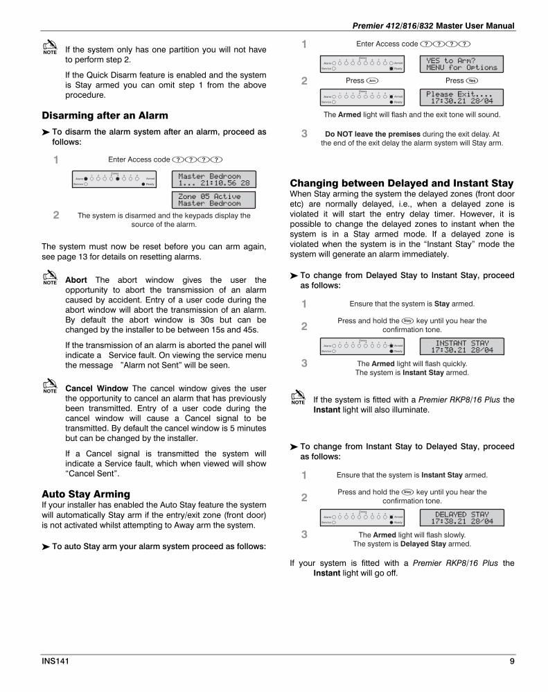
Disarming after an Alarm
To disarm the alarm system after an alarm, proceed as follows:
������ �������
#������)�*����
#������)�*����
�������� ���
The system is disarmed and the keypads display thesource of the alarm.
Enter Access code ����1
2
Armed
Zones87654321
Ready
Alarm
Service
The system must now be reset before you can arm again, see page 13 for details on resetting alarms.
Abort The abort window gives the user the opportunity to abort the transmission of an alarm caused by accident. Entry of a user code during the abort window will abort the transmission of an alarm. By default the abort window is 30s but can be changed by the installer to be between 15s and 45s.
If the transmission of an alarm is aborted the panel will indicate a Service fault. On viewing the service menu the message ”Alarm not Sent” will be seen.
Cancel Window The cancel window gives the user the opportunity to cancel an alarm that has previously been transmitted. Entry of a user code during the cancel window will cause a Cancel signal to be transmitted. By default the cancel window is 5 minutes but can be changed by the installer.
If a Cancel signal is transmitted the system will indicate a Service fault, which when viewed will show “Cancel Sent”.
Auto Stay Arming If your installer has enabled the Auto Stay feature the system will automatically Stay arm if the entry/exit zone (front door) is not activated whilst attempting to Away arm the system.
To auto Stay arm your alarm system proceed as follows:
�+����� ,������
������������
� !�������"
# $%�&���'(�����
The light will flash and the exit tone will sound.Armed
Press �
Enter Access code ����
Press �
Armed
Zones87654321
Ready
Alarm
Service
1
2
3
Armed
Zones87654321
Ready
Alarm
Service
Do NOT leave the premises during the exit delay. Atthe end of the exit delay the alarm system will Stay arm.
Changing between Delayed and Instant Stay When Stay arming the system the delayed zones (front door etc) are normally delayed, i.e., when a delayed zone is violated it will start the entry delay timer. However, it is possible to change the delayed zones to instant when the system is in a Stay armed mode. If a delayed zone is violated when the system is in the “Instant Stay” mode the system will generate an alarm immediately.
To change from Delayed Stay to Instant Stay, proceed as follows:
-$!.�$.�!.��
������������
The light will flash quickly.The system is armed.
ArmedInstant Stay
Press and hold the key until you hear theconfirmation tone.
�
1
2
3
Ensure that the system is armed.Stay
Armed
Zones87654321
Ready
Alarm
Service
If the system is fitted with a Premier RKP8/16 Plus the Instant light will also illuminate.
To change from Instant Stay to Delayed Stay, proceed as follows:
Armed
Zones87654321
Ready
Alarm
Service
� /�� ��!.��
������������
The light will flash slowly.The system is armed.
ArmedDelayed Stay
Press and hold the key until you hear theconfirmation tone.
�
1
2
3
Ensure that the system is armed.Instant Stay
If your system is fitted with a Premier RKP8/16 Plus the Instant light will go off.
INS141 9
Premier 412/816/832 Master User Manual
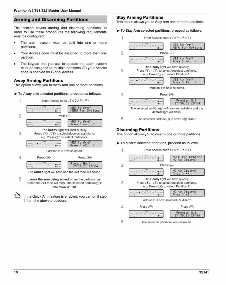
Stay Arming Partitions Arming and Disarming Partitions This option allows you to Stay arm one or more partitions.
This section covers arming and disarming partitions. In order to use these procedures the following requirements must be configured:
To Stay Arm selected partitions, proceed as follows:
� !�������"
�����0�11���2
� !�������"
# $%�&���'(�����
The light will flash quickly.ReadyPress - to select/deselect partitions,
e.g. Press to select Partition 1.�
�
Press �
Enter Access code ����
Armed
Zones87654321
Ready
Alarm
Service
1
2
3
� !�������"
�����0�1���2
Partition 1 is now selected.
Armed
Zones87654321
Ready
Alarm
Service
4 Press �
���������
������������Armed
Zones87654321
Ready
Alarm
Service
5
The selected partition(s) will arm immediately and thelight will flash.Armed
Armed
Zones87654321
Ready
Alarm
Service
The selected partition(s) is now armed.Stay
• The alarm system must be split into one or more partitions.
• Your Access code must be assigned to more than one partition.
• The keypad that you use to operate the alarm system must be assigned to multiple partitions OR your Access code is enabled for Global Access.
Away Arming Partitions This option allows you to Away arm one or more partitions.
To Away arm selected partitions, proceed as follows:
� !�������"
�����0�11���2
Armed
Zones87654321
Ready
Alarm
Service
� !�������"
# $%�&���'(�����
The light will flash quickly.ReadyPress - to select/deselect partitions,
e.g. Press to select Partition 2.�
Press �
Enter Access code ����
Armed
Zones87654321
Ready
Alarm
Service
1
2
3
� !�������"
�����0�1����2
Partition 2 is now selected.
Armed
Zones87654321
Ready
Alarm
Service
4 Press � Press �
�+����� ,������
������������
The light will flash and the exit tone will sound.Armed
Armed
Zones87654321
Ready
Alarm
Service
5 Leave the area being armed, when the partition hasarmed the exit tone will stop. The selected partition(s) is
now Away armed.
Disarming Partitions This option allows you to disarm one or more partitions.
To disarm selected partitions, proceed as follows:
$'����������"
�����0�11���2
# $%�&���'(�����
$'����������"
The light will flash quickly.ReadyPress - to select/deselect partitions,
e.g. Press to select Partition 2.�
Press �
Enter Access code ����
Armed
Zones87654321
Ready
Alarm
Service
1
2
3
$'����������"
�����0�1����2
Partition 2 is now selected for disarm.
Armed
Zones87654321
Ready
Alarm
Service
4 Press �
���������
������������Armed
Zones87654321
Ready
Alarm
Service
5 The selected partitions are disarmed.
Press �
Armed
Zones87654321
Ready
Alarm
Service
If the Quick Arm feature is enabled, you can omit step 1 from the above procedure.
10 INS141
Premier 412/816/832 Master User Manual
Changing to another Partition Normally the remote keypad that you use will be assigned to a particular partition and therefore the zone and status lights will indicate information relevant to the assigned partition. However, you can temporarily switch the remote keypad to a different partition so that the zone and status lights indicate the information relevant to the partition that you have selected. Whilst in this mode you can also use your Access code to arm/disarm the partition you have selected (providing you have access to the selected partition).
In order to use the cross partitioning feature, it is recommend that the system is configured as follows:
• Cross partitioning must be enabled.
• The user must be assigned to multiple partitions.
• The user should be set for “Local Partition Access Only”, see page 21.
• The remote keypads should only be assigned to a single partition.
To change to another partition, proceed as follows:
�3 ���3# ��0����
��� ���������
Enter partition - ,e.g. Press to select Partition 2.
�
Press �
Armed
Zones87654321
Ready
Alarm
Service
1
2
���������
��� ���������
The remote keypad will now indicate informationrelevant to the selected partition.
Armed
Zones87654321
Ready
Alarm
Service
After changing to the selected partition, the remote keypad will only remain in the selected partition for 10 seconds after the last key press. However if an Access code is entered whilst the remote is in this mode, the remote keypad will remain in the selected partition for 1 minute after the last key press.
Bypassing Zones
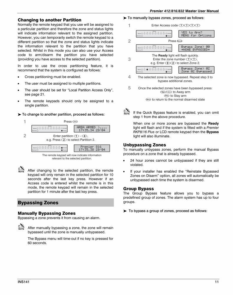
Manually Bypassing Zones Bypassing a zone prevents it from causing an alarm.
After manually bypassing a zone, the zone will remain bypassed until the zone is manually unbypassed.
The Bypass menu will time-out if no key is pressed for 60 seconds.
To manually bypass zones, proceed as follows:
)4(��������0���
1$'$ �)���!! �1
Armed
Zones87654321
Ready
Alarm
Service
� !�������"
# $%�&���'(�����
The light will flash quickly.ReadyEnter the zone number ,
e.g. Enter to select Zone 2.��
�
Press
Enter Access code ����
Armed
Zones87654321
Ready
Alarm
Service
1
2
3
)4(��������0���
��������)4(����*
The selected zone is now bypassed. Repeat step 3 tobypass additional zones.
Armed
Zones87654321
Ready
Alarm
Service
4
5 Once the selected zones have been bypassed press:/ to Away arm
to Stay armto return to the normal disarmed state
��
�
�
If the Quick Bypass feature is enabled, you can omit step 1 from the above procedure.
When one or more zones are bypassed the Ready light will flash and if the system is fitted with a Premier RKP8/16 Plus or LCD remote keypad then the Bypass light will also illuminate.
Unbypassing Zones To manually unbypass zones, perform the manual Bypass procedure on a zone that is already bypassed.
• 24 hour zones cannot be unbypassed if they are still violated.
• If your installer has enabled the “Reinstate Bypassed Zones on Disarm” option, all zones will automatically be unbypassed each time the system is disarmed.
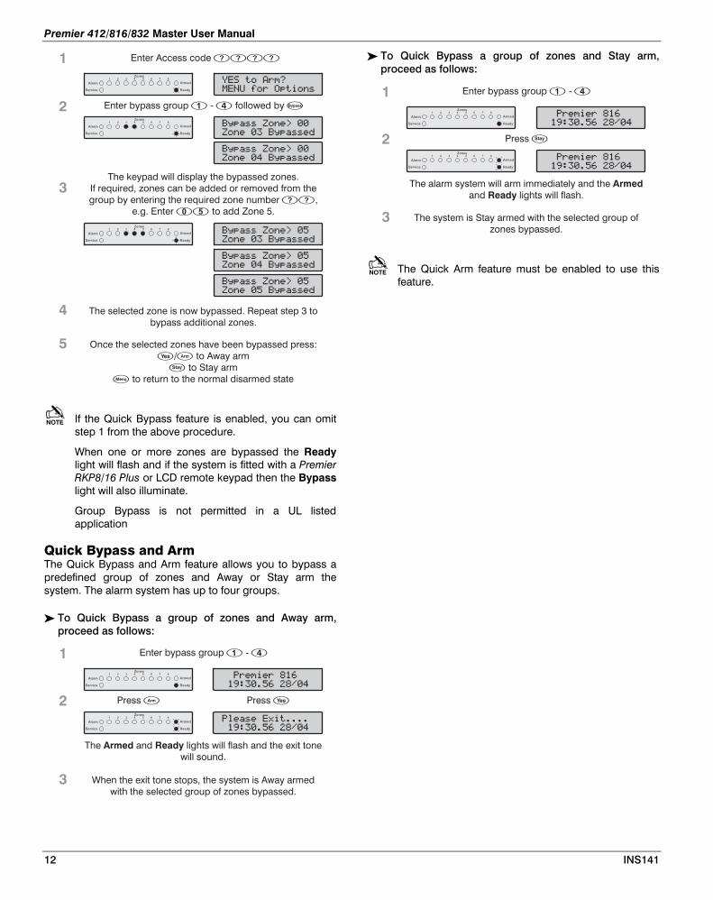
Group Bypass The Group Bypass feature allows you to bypass a predefined group of zones. The alarm system has up to four groups.
To bypass a group of zones, proceed as follows:
INS141 11
Premier 412/816/832 Master User Manual
To Quick Bypass a group of zones and Stay arm, proceed as follows:
Armed
Zones87654321
Ready
Alarm
Service
���������
5���� ������
Enter bypass group � -
Armed
Zones87654321
Ready
Alarm
Service
1
2
3
Press �
���������
5���� ������
The alarm system will arm immediately and theand lights will flash.
ArmedReady
The system is Stay armed with the selected group ofzones bypassed.
)4(��������0���
��������)4(����*
� !�������"
# $%�&���'(�����
The keypad will display the bypassed zones.If required, zones can be added or removed from thegroup by entering the required zone number ,
e.g. Enter to add Zone 5.��
��
Enter bypass group � - followed by
Enter Access code ����
Armed
Zones87654321
Ready
Alarm
Service
1
2
3
)4(��������0��
��������)4(����*
The selected zone is now bypassed. Repeat step 3 tobypass additional zones.
Armed
Zones87654321
Ready
Alarm
Service
4
5 Once the selected zones have been bypassed press:/ to Away arm
to Stay armto return to the normal disarmed state
��
�
�
)4(��������0���
��������)4(����*
)4(��������0��
��������)4(����*
)4(��������0��
������ �)4(����*
Armed
Zones87654321
Ready
Alarm
Service
The Quick Arm feature must be enabled to use this feature.
If the Quick Bypass feature is enabled, you can omit step 1 from the above procedure.
When one or more zones are bypassed the Ready light will flash and if the system is fitted with a Premier RKP8/16 Plus or LCD remote keypad then the Bypass light will also illuminate.
Group Bypass is not permitted in a UL listed application
Quick Bypass and Arm The Quick Bypass and Arm feature allows you to bypass a predefined group of zones and Away or Stay arm the system. The alarm system has up to four groups.
To Quick Bypass a group of zones and Away arm, proceed as follows:
Armed
Zones87654321
Ready
Alarm
Service
���������
5���� ������
Enter bypass group � -
Armed
Zones87654321
Ready
Alarm
Service
1
2
3
Press � Press �
�+����� ,������
5���� ������
The and lights will flash and the exit tonewill sound.
Armed Ready
When the system is Away armedwith the selected group of zones bypassed.
exit tone stops, the
12 INS141
Premier 412/816/832 Master User Manual
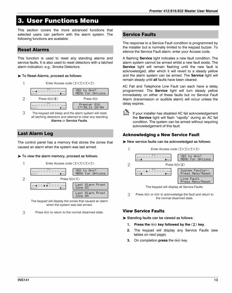
3. User Functions Menu This section covers the more advanced functions that selected users can perform with the alarm system. The following functions are available:
Reset Alarms
This function is used to reset any standing alarms and service faults. It is also used to reset detectors with a latched alarm indication, e.g., Smoke Detectors.
To Reset Alarms, proceed as follows:
���������
������������
� !�������"
# $%�&���'(�����
The keypad will bleep and the alarm system will resetall latching detectors and attempt to clear any standing
or .Alarms Service Faults
Press ��
Enter Access code ����
Press �
Armed
Zones87654321
Ready
Alarm
Service
Armed
Zones87654321
Ready
Alarm
Service
1
2
3
Last Alarm Log
The control panel has a memory that stores the zones that caused an alarm when the system was last armed.
To view the alarm memory, proceed as follows:
/�����+���������
�������
� !�������"
# $%�&���'(�����
The keypad will display the zones that caused an alarmwhen the system was last armed.
Press to return to the normal disarmed state.�
Press ��
Enter Access code ����
Armed
Zones87654321
Ready
Alarm
Service
1
2
3
Armed
Zones87654321
Ready
Alarm
Service
/�����+���������
�������
Service Faults
The response to a Service Fault condition is programmed by the installer but is normally limited to the keypad buzzer. To silence the Service Fault alarm, enter your Access code.
A flashing Service light indicates a new fault condition. The alarm system cannot be armed whilst a new fault exists. The Service light will remain flashing until the new fault is acknowledged, after which it will revert to a steady yellow and the alarm system can be armed. The Service light will remain steady until all faults have been cleared.
AC Fail and Telephone Line Fault can each have a delay programmed. The Service light will turn steady yellow immediately on either of these faults but no Service Fault Alarm (transmission or audible alarm) will occur unless the delay expires.
If your installer has disabled AC fail acknowledgement the Service light will flash “rapidly” during an AC fail condition. The system can be armed without requiring acknowledgement of this fault.
Acknowledging a New Service Fault
New service faults can be acknowledged as follows:
!4�������6+���7
������#��6�3����
� !�������"
# $%�&���'(�����
The keypad will display all Service Faults.
Press or to acknowledge the fault and return tothe normal disarmed state.
� �
Press �
Enter Access code ����1
2
3
/������6+�
������#��6�3����
Armed
Zones87654321
Ready
Alarm
Service
Armed
Zones87654321
Ready
Alarm
Service
View Service Faults
Standing faults can be viewed as follows:
1. Press the key followed by the key.
2. The keypad will display any Service Faults (see tables on next page).
3. On completion press the key.
INS141 13

Premier 412/816/832 Master User Manual
Service Faults Displayed on LED Keypads
Light Fault Condition
1 AC Fail
2 Telephone Line Fault
3 2-Wire Smoke Alarm
4
Box Tamper & Auxiliary Input:
Press to view type, lights 1 - 5 indicate:
1 = Box Tamper 4 = Auxiliary Tamper *
2 = Auxiliary Tamper 5 = Bell Tamper *
3 = Auxiliary PA * = UK Bell Module
5 Date or Time Lost
6 Zone Tamper/Trouble
Press to view zone number
7 Keypad Tamper/Removed
Press to view keypad number
8
Equipment Faults
Press to view fault type, lights 1 - 8 indicate:
1 = Output 1 Fault
2 = Output 2 Fault
3 = Siren/Bell Fault
4 = 2-Wire Smoke Sensor Fault
5 = Auxiliary Fuse Failed
6 = Battery Fault
7 = Service Timer/Zone Soak Test Failed
8 = Com1 Fault or Fail To Communicate
Service Faults Displayed on LCD Keypads
LCD Fault Condition
AC Fail
Telephone Line Fault
2-Wire Smoke Alarm
Box Tamper
Auxiliary Tamper (Aux Input)
Auxiliary Tamper (UK Bell Module)
Bell Tamper (UK Bell Module)
Auxiliary PA (Aux Input)
Date or Time Lost
Zone Tamper/Trouble
Keypad Tamper/Removed
Output 1 Fault
Output 2 Fault
Siren/Bell Fault
2-Wire Smoke Sensor Fault
Auxiliary Fuse Failed
Battery Fault
Service Timer/Zone Soak Test Failed
Com1 Fault or Fail To Communicate
Anti-code Reset
This feature is normally used in the UK where users are not permitted to reset the panel following a communicated alarm. However, the user can reset the panel after entering a unique remote reset number, which is supplied by their installer or ARC.
To perform an Anti-code Reset, proceed as follows:
86����9�*�0���
�����3�(+40""""
� !�������"
# $%�&���'(�����
The keypad will display arandomly generated
4-digit Code.
Press ��
Enter Access code ����1
2
3
Armed
Zones87654321
Ready
Alarm
Service
Armed
Zones87654321
Ready
Alarm
Service
Armed
Zones87654321
Ready
Alarm
Service
Armed
Zones87654321
Ready
Alarm
Service
Armed
Zones87654321
Ready
Alarm
Service
Contact your ARC/Installer to obtain a Anti-code Resetnumber.
Tel No.__________________________________________
Enter the Anti-code Reset number given to you by yourARC/Installer .
If the code is accepted, the keypad will sound anacceptance tone and the system will reset and return to
the normal disarmed state.
����
4
Toggle Chime On and Off
When a zone is enabled for Chime the keypad will generate a Chime tone every time the zone is violated. This function allows you to turn the Chime feature on and off.
To toggle Chime on and off, proceed as follows:
If Chime was off, it will turn on and the keypad willsound the Chime tone. If Chime was on, it will turn off
and the keypad will sound the acceptance tone.
Enter �
Enter Access code ����
Armed
Zones87654321
Ready
Alarm
Service
1
2
3
���������
������������
Armed
Zones87654321
Ready
Alarm
Service
Press �
� !�������"
# $%�&���'(�����
14 INS141
Premier 412/816/832 Master User Manual
INS141 15
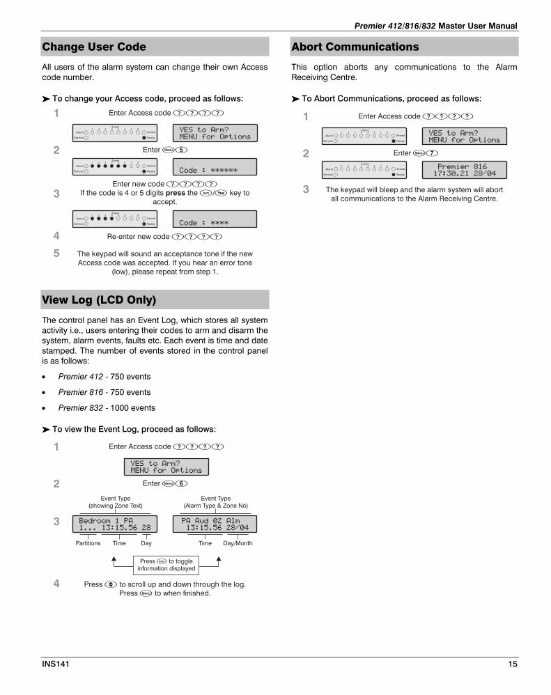
Change User Code Abort Communications
All users of the alarm system can change their own Access code number.
This option aborts any communications to the Alarm Receiving Centre.
To change your Access code, proceed as follows:
� !�������"
# $%�&���'(�����
9�*����111111
Enter new codeIf the code is 4 or 5 digits the / key to
accept.
����
��press
Enter ��
Enter Access code ����
Armed
Zones87654321
Ready
Alarm
Service
1
2
3
9�*����1111Armed
Zones87654321
Ready
Alarm
Service
4
5 The keypad will sound an acceptance tone if the newAccess code was accepted. If you hear an error tone
(low), please repeat from step 1.
Armed
Zones87654321
Ready
Alarm
Service
Re-enter new code ����
To Abort Communications, proceed as follows:
The keypad will bleep and the alarm system will abortall communications to the Alarm Receiving Centre.
Enter ��
Enter Access code ����
Armed
Zones87654321
Ready
Alarm
Service
1
2
3
���������
������������
Armed
Zones87654321
Ready
Alarm
Service
� !�������"
# $%�&���'(�����
View Log (LCD Only)
The control panel has an Event Log, which stores all system activity i.e., users entering their codes to arm and disarm the system, alarm events, faults etc. Each event is time and date stamped. The number of events stored in the control panel is as follows:
• Premier 412 - 750 events
• Premier 816 - 750 events
• Premier 832 - 1000 events
To view the Event Log, proceed as follows:
)�*��������
������ � ���
Day
Event Type(showing Zone Text)
TimePartitions Day/Month
Event Type(Alarm Type & Zone No)
Time
����6*�����+�
�� � ������
Press to toggleinformation displayed
�
� !�������"
# $%�&���'(�����
Enter ��
Enter Access code ����1
2
3
4 Press to scroll up and down through the log.Press to when finished.
�
�

Premier 412/816/832 Master User Manual
4. System Program Menus The Master User and Users with the relevant access level can access the System Program Menus. These menus allow the users access to the more advanced features and functions of the alarm system.
The following programming menus are available:
Menu Function Page
Programming Users
Program User 19
User Options 1 20
User Options 2 20
User Options 3 20
User Text 21
Program Standard Users 21
System Tests and Utilities
Walk Test 23
Test Speakers and Outputs 23
Send Test Call 23
Enable Download Access 23
Start Call Back 23
Program Time 23
Program Date 23
Program Banner Text 23
Print 100 Events 23
Exit Program Mode 23
Menus - are restricted to Access codes enabled for Code Programming (Master Users).
Menus - are restricted to Access codes enabled for User Programming.
To abort programming at any stage and preserve the original settings, press . The alarm system will automatically exit program mode if no key is pressed for 60 seconds.
For UL/CUL Installations System tests are options to Utilities are options to
For UL/CUL Installations Test in Progress
When a test is in progress it will be displayed at all the keypads connected to the system.
For UL/CUL Installations Automated Termination
The system does not automatically terminate a test. Termination of a test can only be achieved manually by entering Menus .
To access the programming menu, enter your Access code and press followed by :
���:������:�#��6
�����9�*��0��""
Armed
Zones87654321
Ready
Alarm
Service
Enter Access code
Then press then
����
� �
All Zone lights lit and
light flashesReady
Enter menu command��
A programming menu is selected by entering a two-digit menu code. On completion of each menu option, the system reverts to the main programming menu, allowing other programming menu options to be accessed.
To exit the programming menu, enter or press the key, the system will revert to normal operation:
���:������:�#��6
�����9�*��0��""
Armed
Zones87654321
Ready
Alarm
Service
All Zone lights lit and
light flashesReady
To exit programming mode,
enter or press�� �
���������
��� � 5������
Armed
Zones87654321
Ready
Alarm
Service
All zones clear and
light on.Ready
LCD shows banner text
and time/date.
16 INS141
Premier 412/816/832 Master User Manual
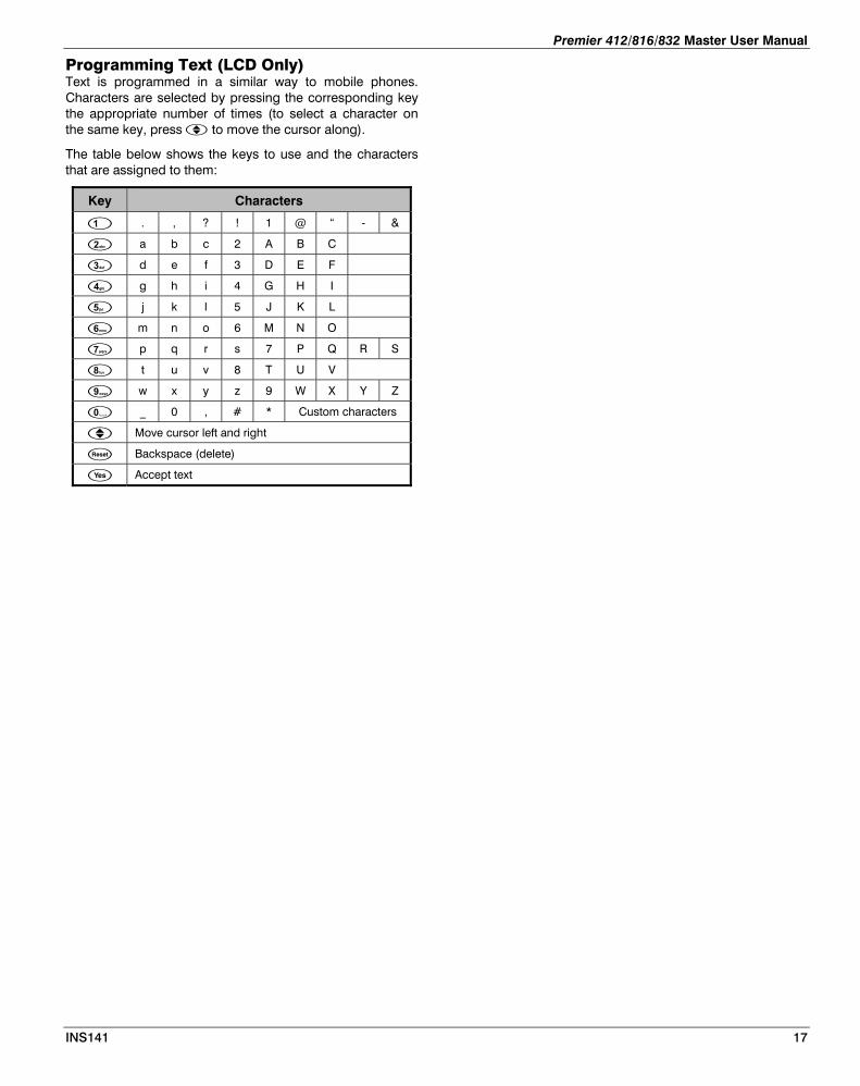
Programming Text (LCD Only) Text is programmed in a similar way to mobile phones. Characters are selected by pressing the corresponding key the appropriate number of times (to select a character on the same key, press to move the cursor along).
The table below shows the keys to use and the characters that are assigned to them:
Key Characters
. , ? ! 1 @ “ - &
a b c 2 A B C
d e f 3 D E F
g h i 4 G H I
j k l 5 J K L
m n o 6 M N O
p q r s 7 P Q R S
t u v 8 T U V
w x y z 9 W X Y Z
_ 0 , # * Custom characters
Move cursor left and right
Backspace (delete)
Accept text
INS141 17
Premier 412/816/832 Master User Manual
Programming Users
Led KeyOffOnSlow FlashFast Flash
Enter Access code
Then press then
����
� �
���:������:�#��6
�����9�*��0��""
Armed
Zones87654321
Ready
Alarm
Service
Continues onNext Page
�
���:����%������
�����%����$��""
��
Program User
Armed
Zones87654321
Ready
Alarm
Service
�
%�������'(�����
�����%����$��""
��
User Options 1
Armed
Zones87654321
Ready
Alarm
Service
Enter User Number��.
%�������'(�����
0�111 ���2
Armed
Zones87654321
Ready
Alarm
Service
Use keys - toselect/deselect Options.Then press or
� �
� �
User Options 1�
�
�
�
�
�
Enable for Partition 1
Allow ArmingAllow BypassingAllow DisarmingAllow User Functions
Enable for Partition 2Enable for Partition 3 ( )Enable for Partition 4 ( )
Premier 816/832Premier 816/832
�
User Options 3�
�
�
�
�
�
Allow Engineer Code ProgrammingAllow NVM LockingAllow Engineer ProgrammingAllow Test Call TransmissionAllow Alarm/Fault AcknowledgementAllow User ProgrammingAllow User Code ProgrammingLocal Partition Access Only
%�������'(������
�����%����$��""
��
%�������'(������
0�1111 111�2
Armed
Zones87654321
Ready
Alarm
Service
User Options 3
Armed
Zones87654321
Ready
Alarm
Service
Use keys - toselect/deselect Options.Then press or
� �
� �
Enter User Number��.
Enter User Number��.
���:����%������
9�*����111111
Armed
Zones87654321
Ready
Alarm
Service
Enter Code
Press or if code isless than 6 digits.
����
� �
���:����%������
9�*����1111
Armed
Zones87654321
Ready
Alarm
Service
Re-enter New Code����
A
Return to point A
�
User Options 2�
�
�
�
�
Enable One Time Use Access CodeTime Lock Code with Control Timer 1Enable Open ReportingEnable Close ReportingEnable User as Duress CodeActivate Door Strike OutputAllow Global Bell/Sounder Silence
� Disable Remote Access
%�������'(������
�����%����$��""
�
%�������'(������
0�11��1111�2
Armed
Zones87654321
Ready
Alarm
Service
User Options 2
Armed
Zones87654321
Ready
Alarm
Service
Use keys - toselect/deselect Options.Then press or
� �
� �
Enter User Number��.
18 INS141
Premier 412/816/832 Master User Manual
From
Previous Page
�
Text Editing Keys
�
�
�
�
�
�
�
. , ? ! 1 @ ” - &
a b c 2 A B C
d e f 3 D E F
g h I 4 G H I
j k l 5 J K L
m n o 7 M N O
p q r s 7 P Q R S
t u v 8 T U V
�
�
w x y z 9 W X Y Z
Space 0 , # *
Move Left/Right
Backspace (delete)
Use keys to enter/edit text.
Then press to accept.�
�:�����
%�������.�,��� �:�����
;�������.�,�
Use to select User.
Press
�
� to edit text.
User Text
�
��
Delete User
Armed
Zones87654321
Ready
Alarm
Service
Enter User Number
��.Armed
Zones87654321
Ready
Alarm
Service
Press
���:����%������
�����%����$��""
���:����%������
9�*����111111
���:����%������
�����%����$��""
��Armed
Zones87654321
Ready
Alarm
Service
Enter User Number
��.
���:����%������
9�*����111111
Armed
Zones87654321
Ready
Alarm
Service
Enter Code
Press or if code is
less than 6 digits.
����
� �
���:����%������
9�*����1111
Armed
Zones87654321
Ready
Alarm
Service
Re-enter New Code����
Program Standard Users
�
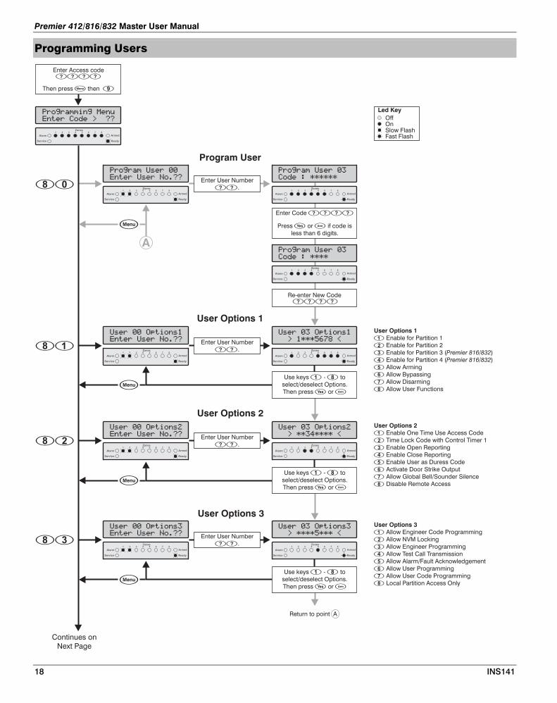
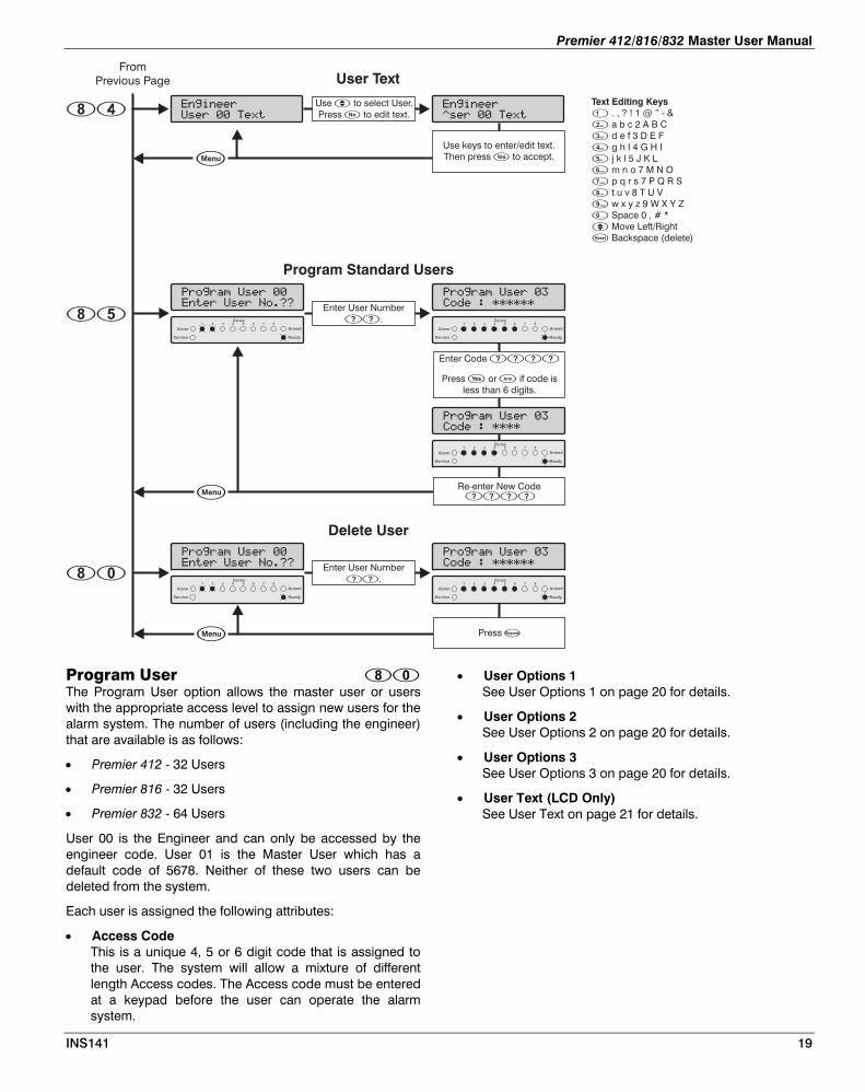
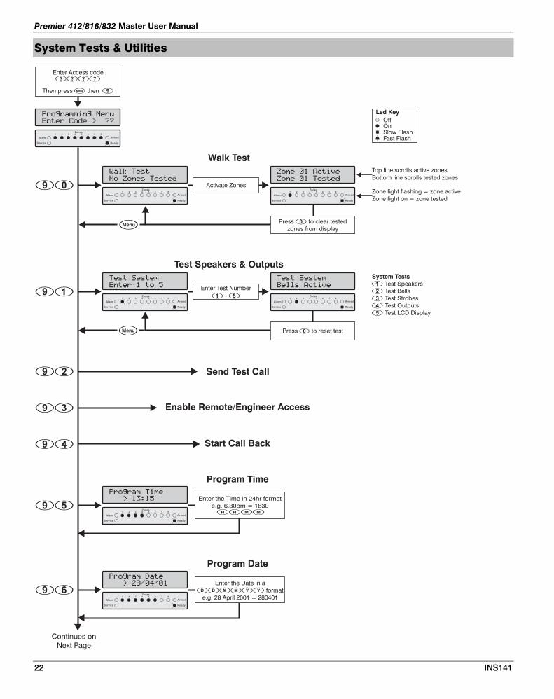
Program User • User Options 1 See User Options 1 on page 20 for details. The Program User option allows the master user or users
with the appropriate access level to assign new users for the alarm system. The number of users (including the engineer) that are available is as follows:
• User Options 2 See User Options 2 on page 20 for details.
• User Options 3 See User Options 3 on page 20 for details.
• Premier 412 - 32 Users
• Premier 816 - 32 Users • User Text (LCD Only)
See User Text on page 21 for details. • Premier 832 - 64 Users
User 00 is the Engineer and can only be accessed by the engineer code. User 01 is the Master User which has a default code of 5678. Neither of these two users can be deleted from the system.
Each user is assigned the following attributes:
• Access Code This is a unique 4, 5 or 6 digit code that is assigned to the user. The system will allow a mixture of different length Access codes. The Access code must be entered at a keypad before the user can operate the alarm system.
INS141 19
Premier 412/816/832 Master User Manual
User Options 1 User Options 1 can be enabled or disabled for a selected user so that the level of access to the system may be altered. The following options are available:
Enable for Partition 1 On: The user can access Partition 1. Off: The user cannot access Partition 1.
Enable for Partition 2 On: The user can access Partition 2. Off: The user cannot access Partition 2.
Enable for Partition 3 (Premier 816/832 Only) On: The user can access Partition 3. Off: The user cannot access Partition 3.
Enable for Partition 4 (Premier 816/832 Only) On: The user can access Partition 4. Off: The user cannot access Partition 4.
Allow Arming On: The user can arm the partitions they have been given
access to. Off: The user cannot arm any partitions.
Allow Bypassing On: The user can bypass zones in partitions they have
been given access to. Off: The user cannot bypass zones.
Allow Disarming On: The user can disarm the partitions they have been
given access to. Off: The user cannot disarm any partitions.
The Engineer code (User 00) can only disarm the system if the system was armed with the Engineer code.
Allow User Functions On: The user can access the following user functions:
• Reset • View Alarm Log • View Service Faults • Enable Chime • Change Own Code
Off: The user cannot access the above user functions.
User Options 2 User Options 2 can be enabled or disabled for a selected user so that the level of access to the system may be altered. The following options are available:
Enable One Time Use Access Code On: The Access code can only be used once to arm and
disarm the system. After the Access code has been used to disarm the system it is automatically deleted.
Off: The Access code behaves normally.
Time Lock Code with Control Timer 1 On: When Control Timer 1 is on, the Access code will not
be accepted by the system. When Control Timer 1 is off, the Access code will be accepted by the system.
Off: The Access code will be accepted at all times.
Enable Open Reporting On: The system will report an ‘Open’ condition to the alarm
receiving centre when the Access code is used to disarm one or more partitions.
Off: The system will not report an ‘Open’ status.
The panel will always send an open signal after an alarm even if this option is disabled.
Enable Close Reporting On: The system will report a ‘Close’ condition to the
monitoring station when the Access code is used to arm one or more partitions.
Off: The system will not report a ‘Close’ condition.
Enable User as Duress Code On: The Access code will report a ‘Duress’ condition to the
monitoring station when the Access code is used. Off: The Access code behaves normally.
Activate Door Strike Output On: When a user Access code is entered, the output type
“Door Strike” is activated for 2 seconds. Off: The user Access code will not activate the “Door
Strike” output.
Allow Global Bell/Sounder Silence On: This option allows users to silence the bell and internal
sounder for any partition, even if the user is not assigned to the partition that is in alarm. The user cannot disarm or reset the partition if they are not assigned to it.
Off: The user can only silence alarms for partitions that are assigned to their code.
Disable Remote Access On: The remote access feature is disabled for the selected
user. Off: The remote access feature is enabled for the selected
user.
The Remote Access feature is only available on the Premier 816+ and Premier 832. It allows the user to dial in to their alarm system remotely control the system using a standard touch-tone telephone.
User Options 3 User Options 3 can be enabled or disabled for a selected user so that the level of access to the system may be altered. The following options are available:
Allow Engineer Code Programming On: The Access code can access User 00 (Engineer) in the
Program New Users menu (menu 80). Off: The Access code cannot access user 00 in the
Program New Users menu.
20 INS141

Premier 412/816/832 Master User Manual
INS141 21
Allow NVM Locking On: The Access code is allowed to lock/unlock the NVM
(providing “Allow Engineer Programming” is enabled). Once the NVM is locked the “Load Defaults” jumper pins on the main control panel are disabled, thus preventing the panel from being defaulted.
Off: The Access code cannot lock/unlock the NVM.
Allow Engineer Programming On: The Access code can access the Engineer
programming menus. Off: The Access code cannot access the Engineer
programming menus.
Allow Test Call Transmission On: The Access code can perform a test transmission to
the monitoring station (menu 92, see page 23). Off: The Access code cannot perform a test transmission.
Allow Alarm/Fault Acknowledgement On: The Access code can be used to acknowledge and
reset alarms and service faults. A user with this option can disarm the system after an alarm, even if the user does not have the "Allow Disarming" option.
Off: The Access code cannot be used to acknowledge and reset alarms and service faults.
Allow User Programming On: The Access code can access the user program menus
(menu 90 - 98). Off: The Access code cannot access the user program
menus.
Allow User Code Programming On: The Access code can access users 01 to 31 in the
User programming menus (menus 80 - 85). Off: The Access code cannot access user 01 to 31 in the
User programming menus.
Local Partition Access Only On: The Access code can only be used to arm and disarm
the partitions that are assigned to the remote keypad. For example, if the user is assigned to all four partitions and they use a remote keypad that is only assigned to Partition 1, they will only be permitted to arm and disarm Partition 1 at that particular remote keypad.
Off: The Access code can be used at any remote keypad (Global Access).
User Text (LCD Only) If the system is fitted with a LCD remote keypad you can assign up to 8 characters of text to each user. This text is used when viewing the system Event Log, see page 15. User text is programmed in a similar way to mobile phones. Characters are selected by pressing the corresponding key the appropriate number of times (to select a character on the same key, press to move the cursor along). For details on entering text, see page 17.
Program Standard Users This menu option allows you to add “Standard” users to the system. The user will automatically be assigned the following options:
User Options 1: Partition 1 Access
Allow Arming
Allow Bypassing
Allow Disarming
Allow User Functions
User Options 2: Enable Open Reporting
Enable Close Reporting
Allow Global Bell/Sounder Silence
User Options 3: Allow Alarm/Fault Acknowledgement
Premier 412/816/832 Master User Manual
System Tests & Utilities
Led Key
OffOnSlow FlashFast Flash
Enter Access code
Then press then
����
� �
���:������:�#��6
�����9�*��0��""
Armed
Zones87654321
Ready
Alarm
Service
Continues on
Next Page
�
<�+=�.���
$��������.����*
��
Walk Test
Armed
Zones87654321
Ready
Alarm
Service
Activate Zones
�������������
�������.����*
Armed
Zones87654321
Ready
Alarm
Service
Press to clear tested
zones from display
�
Top line scrolls active zones
Bottom line scrolls tested zones
Zone light flashing = zone active
Zone light on = zone tested
�
.����!4����
���������
��
Test Speakers & Outputs
Armed
Zones87654321
Ready
Alarm
Service
Enter Test Number
� - �
.����!4����
)�++��������
Armed
Zones87654321
Ready
Alarm
Service
System Tests
�
�
�
Test Speakers
Test Bells
Test Strobes
Test Outputs
� Test LCD Display
Press to reset test�
�� Enable Remote/Engineer Access
�� Start Call Back
� Send Test Call
���:��������
0��������
��
Program Date
Armed
Zones87654321
Ready
Alarm
Service
Enter the Date in a
format
e.g. 28 April 2001 = 280401
������
���:����.���
0���
��
Program Time
Armed
Zones87654321
Ready
Alarm
Service
Enter the Time in 24hr format
e.g. 6.30pm = 1830����
22 INS141
Premier 412/816/832 Master User Manual
From
Previous Page
�
Text Editing Keys
�
�
�
�
�
�
�
. , ? ! 1 @ ” - &
a b c 2 A B C
d e f 3 D E F
g h I 4 G H I
j k l 5 J K L
m n o 7 M N O
p q r s 7 P Q R S
t u v 8 T U V
�
�
�
�
w x y z 9 W X Y Z
Space 0 , # *
Move Left/Right
Backspace (delete)
Use keys to enter/edit text.
Then press to accept.�
���������!�
)������.�,��� ���������!�
;������.�,�Press � to edit text.
Banner Text (LCD Only)
�� Exit Program Mode
�� Print 100 Events
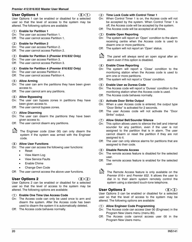
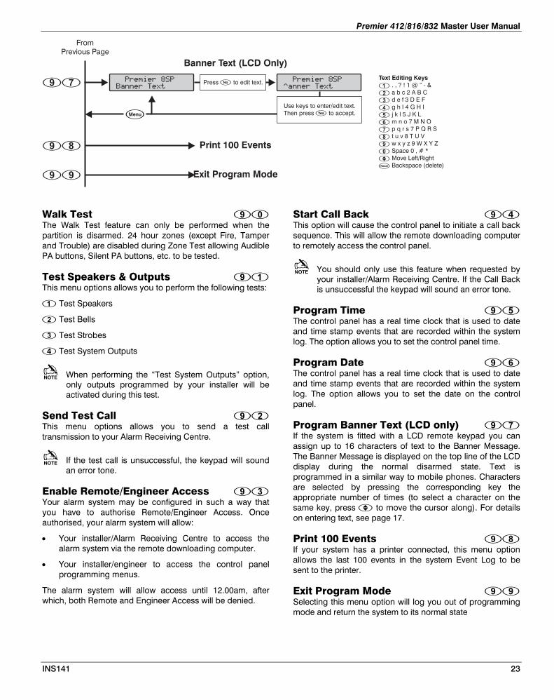
Walk Test Start Call Back The Walk Test feature can only be performed when the partition is disarmed. 24 hour zones (except Fire, Tamper and Trouble) are disabled during Zone Test allowing Audible PA buttons, Silent PA buttons, etc. to be tested.
This option will cause the control panel to initiate a call back sequence. This will allow the remote downloading computer to remotely access the control panel.
You should only use this feature when requested by your installer/Alarm Receiving Centre. If the Call Back is unsuccessful the keypad will sound an error tone.
Test Speakers & Outputs This menu options allows you to perform the following tests:
Test Speakers Program Time
Test Bells The control panel has a real time clock that is used to date and time stamp events that are recorded within the system log. The option allows you to set the control panel time.
Test Strobes
Test System Outputs Program Date When performing the “Test System Outputs” option,
only outputs programmed by your installer will be activated during this test.
The control panel has a real time clock that is used to date and time stamp events that are recorded within the system log. The option allows you to set the date on the control panel.
Send Test Call Program Banner Text (LCD only) This menu options allows you to send a test call
transmission to your Alarm Receiving Centre. If the system is fitted with a LCD remote keypad you can assign up to 16 characters of text to the Banner Message. The Banner Message is displayed on the top line of the LCD display during the normal disarmed state. Text is programmed in a similar way to mobile phones. Characters are selected by pressing the corresponding key the appropriate number of times (to select a character on the same key, press to move the cursor along). For details on entering text, see page 17.
If the test call is unsuccessful, the keypad will sound an error tone.
Enable Remote/Engineer Access Your alarm system may be configured in such a way that you have to authorise Remote/Engineer Access. Once authorised, your alarm system will allow:
Print 100 Events • Your installer/Alarm Receiving Centre to access the alarm system via the remote downloading computer. If your system has a printer connected, this menu option
allows the last 100 events in the system Event Log to be sent to the printer.
• Your installer/engineer to access the control panel programming menus.
Exit Program Mode The alarm system will allow access until 12.00am, after which, both Remote and Engineer Access will be denied. Selecting this menu option will log you out of programming
mode and return the system to its normal state
INS141 23

Premier 412/816/832 Master User Manual
5. Fire Safety & Maintenance
Fire Safety
Fire Alarm Operation Alarm On a fire alarm, the bell or siren will pulse ON and OFF. If your system is fitted with a Premier RKP8/16 Plus then the Fire light will be illuminated. The alarm is also transmitted to the Alarm Receiving Centre, if your installer has enabled this feature.
Silence To silence the bell or siren, enter your Access code.
Resetting Smoke Detectors Once the smoke detector is reset, if it still detects smoke, the alarm sequence will resound as described above. If there is no smoke, the system will return to normal operation.
To reset smoke detectors, proceed as follows:
1. Enter your Access code .
2. Press the key followed by the key. If your system is fitted with either a Premier RKP8/16 Plus or LCD remote keypad then press the key.
3. The keypad will bleep and the alarm system will reset all latching detectors.
If you suspect that a fire alarm has transmitted and that there is no fire condition, call the alarm receiving centre to avoid an unnecessary response. If a fire condition is apparent, follow your evacuation plan immediately. If the alarm sounds at night, evacuate immediately.
The description above may not be applicable depending on how your installer has programmed the fire alarm operations on your system. Ask your installer for more information regarding your system's operation.
Household Fire Safety Audit Most fires occur in the home. To minimise the risk of fire, it is recommended that a household safety audit is conducted and a fire escape plan is developed.
• Are all electrical appliances and outlets in a safe condition? Check for frayed cords, overloaded lighting circuits, etc. If you are uncertain about the condition of your electrical appliances or household service, have a professional evaluate these units.
• Are all flammable liquids stored safely in closed containers in a well ventilated cool area? Cleaning with flammable liquids should be avoided.
• Are fire hazardous materials (matches) well out of reach of children?
• Are furnaces and wood burning appliances properly installed, clean and in good working order? Have a professional evaluate these appliances.
Fire Escape Planning There is often very little time between the detection of a fire and the time it becomes deadly. It is therefore very important that a family escape plan be developed and rehearsed.
1. Every family member should participate in developing the escape plan.
2. Study the possible escape routes from each location within the house. Since many fires occur at night, special attention should be given to the escape routes from sleeping quarters.
3. Escape from a bedroom must be possible without opening the interior door. Consider the following when making your escape plans:
• Make sure that all perimeter doors and windows are easily opened. Ensure that they are not painted shut and that their locking mechanisms operate smoothly.
• If opening or using the exit is too difficult for children, the elderly or handicapped, plans for rescue should be developed. This includes making sure that those who are to perform the rescue can promptly hear the fire warning signal.
• If the exit is above the ground level, an approved fire ladder or rope should be provided as well as training in its use.
• Exits on the ground level should be kept clear. Be sure to remove snow from exterior patio doors in winter; outdoor furniture or equipment should not block exits.
• Each person should know of a predetermined assembly point where everyone can be accounted for i.e. across the street or at a neighbour's house. Once everyone is out of the building, call the Fire Services.
• A good plan emphasises quick escape. Do not investigate or attempt to fight the fire, and do not gather belongings or pets as this wastes valuable time. Once outside, do not re-enter the house. Wait for the Fire Services.
• Write the fire escape plan down and rehearse it frequently so that should an emergency arise, everyone will know what to do. Revise the plan as conditions change, such as the number of people in the home, or if there are changes to the building's construction.
24 INS141

Premier 412/816/832 Master User Manual
• Make sure your fire warning system is operational by conducting weekly tests (see “Fire Alarm Operation” on page 24). If you are unsure about system operation, contact your installing dealer.
• We recommend that you contact your local fire department and request further information on fire safety and escape planning. If available, have your local fire prevention officer conduct an in-house fire safety inspection.
• Further recommendations and links to useful documents can be found on page 24.
Maintenance
With normal use, the system requires minimum maintenance. The following points should be observed.
1. Do not wash the security control panel or keypads with a wet cloth. Light dusting with a slightly moistened cloth should remove normal accumulations of dust.
2. The battery test is designed to determine battery condition. We recommend, however, that the stand-by batteries are replaced every five years.
3. For other system devices such as smoke detectors, passive infrared, ultrasonic or microwave motion detectors or glass-break detectors, consult the respective manufacturer’s literature for testing and maintenance.
Glossary
Glossary of terms used in this manual:
Access Code: A four, five or six digit code that is used to operate the alarm system.
Alarm Receiving Centre: A remote location where alarm status data is received via the telephone line from the control panel.
Bypass: A feature that allows the user to exclude selected zones from being monitored by the alarm system.
Chime: A feature that allows the keypads and internal sounder to generate a ding-dong sound whenever the selected zones are violated.
Duress Code: A special type of Access code that reports a signal to the alarm receiving centre that indicates the system is being operated under duress. This code when entered acts like a User code on the premises but will send a Duress code to the monitoring station.
Forced Armable: An option that can be selected on a zone by zone basis, that will allow the system to be armed, even if the selected zone is violated.
Group Bypass: A feature that allows the user to bypass a group of zones in one go.
Partition: One or more zones that make up an individual area. This area can independently be armed and disarmed from other partitions.
Service: A condition that will indicate that a problem has occurred with the alarm system or with one of its detection devices.
Zone: A zone is an area of protection that has one or more detection sensors connected to it (motion detectors, glass-break detectors, door contacts or shock sensors).
For UL/CUL Installations Swinger Shutdown: The Swinger Shutdown feature is used to prevent repeated alarm transmissions from a faulty detector or ”swinging door”. By default the swinger shutdown count of 1 will shut down the zone after 1 trip. The zone will be restored when the system is reset. This feature is only programmable by the Installer.
INS141 25

Premier 412/816/832 Master User Manual
Basic fire escape planning
Your ability to get out depends on advance warning from smoke alarms and advance planning.
• Pull together everyone in your household and make a plan. Walk through your home and inspect all possible exits and escape routes. Households with children should consider drawing a floor plan of your home, marking two ways out of each room, including windows and doors. Also, mark the location of each smoke alarm. For easy planning, download NFPA's escape planning grid (http://www.nfpa.org/assets/files/PDF/FPW07/escapeplangrid07.pdf) (PDF, 634 KB). This is a great way to get children involved in fire safety in a non-threatening way.
• Download NFPA’s Escape Planning Tips (http://www.nfpa.org/assets/files/PDF/Public%20Education/EscapePlanningTips.pdf)
• Install smoke alarms in every sleeping room, outside each sleeping area and on every level of the home. NFPA 72, National Fire Alarm Code® (http://www.nfpa.org/catalog/product.asp?pid=7207) requires interconnected smoke alarms throughout the home. When one sounds, they all sound.
• Everyone in the household must understand the escape plan. When you walk through your plan, check to make sure the escape routes are clear and doors and windows can be opened easily.
• Choose an outside meeting place (i.e. neighbor's house, a light post, mailbox, or stop sign) a safe distance in front of your home where everyone can meet after they've escaped. Make sure to mark the location of the meeting place on your escape plan.
• Go outside to see if your street number is clearly visible from the road. If not, paint it on the curb or install house numbers to ensure that responding emergency personnel can find your home.
• Have everyone memorize the emergency phone number of the fire department. That way any member of the household can call from a neighbor's home or a cellular phone once safely outside.
• If there are infants, older adults, (http://www.nfpa.org/itemDetail.asp?categoryID=409&itemID=17840&URL=Research%20&%20Reports/Fact%20sheets/Home%20escape%20planning/Escape%20planning%20for%20older%20adults) or family members with mobility limitations, make sure that someone is assigned to assist them in the fire drill and in the event of an emergency. Assign a backup person too, in case the designee is not home during the emergency.
• If windows or doors in your home have security bars, (http://www.nfpa.org/itemDetail.asp?categoryID=293&itemID=19175&URL=Research%20&%20Reports/Fact%20sheets/Safety%20in%20the%20home/Security%20bars) make sure that the bars have emergency release devices inside so that they can be opened immediately in an emergency. Emergency release devices won't compromise your security - but they will increase your chances of safely escaping a home fire.
• Tell guests or visitors to your home about your family's fire escape plan. When staying overnight at other people's homes, ask about their escape plan. If they don't have a plan in place, offer to help them make one. This is especially important when children are permitted to attend "sleepovers" at friends' homes. See NFPA's "Sleepover fire safety for kids" (http://www.nfpa.org/categoryList.asp?categoryID=411&URL=Research%20&%20Reports/Fact%20sheets/Home%20escape%20planning/Sleepover%20fire%20safety%20for%20kids) fact sheet.
• Be fully prepared for a real fire: when a smoke alarm sounds, get out immediately. Residents of high-rise and apartment buildings may be safer "defending in place." (http://www.nfpa.org/itemDetail.asp?categoryID=407&itemID=17739&URL=Research%20&%20Reports/Fact%20sheets/Home%20escape%20planning/Tips%20for%20people%20living%20in%20apartment%20buildings)
• Once you're out, stay out! Under no circumstances should you ever go back into a burning building. If someone is missing, inform the fire department dispatcher when you call. Firefighters have the skills and equipment to perform rescues.
Putting your plan to the test
• Practice your home fire escape plan twice a year, making the drill as realistic as possible.
• Make arrangements in your plan for anyone in your home who has a disability.
• Allow children to master fire escape planning and practice before holding a fire drill at night when they are sleeping. The objective is to practice, not to frighten, so telling children there will be a drill before they go to bed can be as effective as a surprise drill.
• It's important to determine during the drill whether children and others can readily waken to the sound of the smoke alarm. If they fail to awaken, make sure that someone is assigned to wake them up as part of the drill and in a real emergency situation.
• If your home has two floors, every family member (including children) must be able to escape from the second floor rooms. Escape ladders can be placed in or near windows to provide an additional escape route. Review the manufacturer's instructions carefully so you'll be able to use a safety ladder in an emergency. Practice setting up the ladder from a first floor window to make sure you can do it correctly and quickly. Children should only practice with a grown-up, and only from a first-story window. Store the ladder near the window, in an easily accessible location. You don't want to have to search for it during a fire.
• Always choose the escape route that is safest – the one with the least amount of smoke and heat – but be prepared to escape under toxic smoke if necessary. When you do your fire drill, everyone in the family should practice getting low and going under the smoke to your exit.
• Closing doors on your way out slows the spread of fire, giving you more time to safely escape.
• In some cases, smoke or fire may prevent you from exiting your home or apartment building. To prepare for an emergency like this, practice "sealing yourself in for safety" as part of your home fire escape plan. Close all doors between you and the fire. Use duct tape or towels to seal the door cracks and cover air vents to keep smoke from coming in. If possible, open your windows at the top and bottom so fresh air can get in. Call the fire department to report your exact location. Wave a flashlight or light-colored cloth at the window to let the fire department know where you are located.
26 INS141

Premier 412/816/832 Master User Manual
6. FCC Statements
This equipment complies with Part 68 of the FCC rules and the requirements adopted by the ACTA. On the exterior of the cabinet of this equipment is a label that contains, among other information, a product identifier in the format 5MI1AL09B P832P816. If requested, this number must be provided to the telephone company.
ACTA Registration Number: 5MI1AL09B P832P816
Ringer Equivalence Number (REN): 0.9B
Facility Interface Code (FIC): 02LS2
Service Order Code (SOC): SOC9.0Y
USOC Jack Type: RJ-31X
A FCC compliant telephone cord and modular plug should be provided with this equipment. This equipment is designed to be connected to the telephone network or premises wiring using a compatible modular jack that is Part 68 compliant. See Installation Instructions for details.
The REN is used to determine the quantity of devices that may be connected to the telephone line. Excessive RENs on the telephone line may result in the devices not ringing in response to an incoming call. Typically, the sum of RENs should not exceed five (5.0). To be certain of the number of devices that may be connected to a line (as determined by the total RENs) contact the local telephone company.
If this equipment Premier 832 & Premier 816 causes harm to the telephone network, the telephone company will notify you in advance that temporary discontinuance of service may be required. But if advance notice isn't practical, the telephone company will notify the customer as soon as possible. Also, you will be advised of your right to file a complaint with the FCC if you believe it is necessary.
The telephone company may make changes to it's facilities, equipment, operations or procedures that could affect the operation of the equipment. If this happens the telephone company will provide advance notice so you can make the necessary modifications to maintain uninterrupted service.
If trouble is experienced with this equipment Premier 832, Premier 816, for repair or warranty information, please contact Space Age Electronics 978 212 1314. If the equipment is causing harm to the telephone network, the telephone company may request that you disconnect the equipment until the problem is resolved.
Connection to party line service is subject to state tariffs. (Contact the state public utility commission, public service commission or corporation commission for information.)
INS141 27
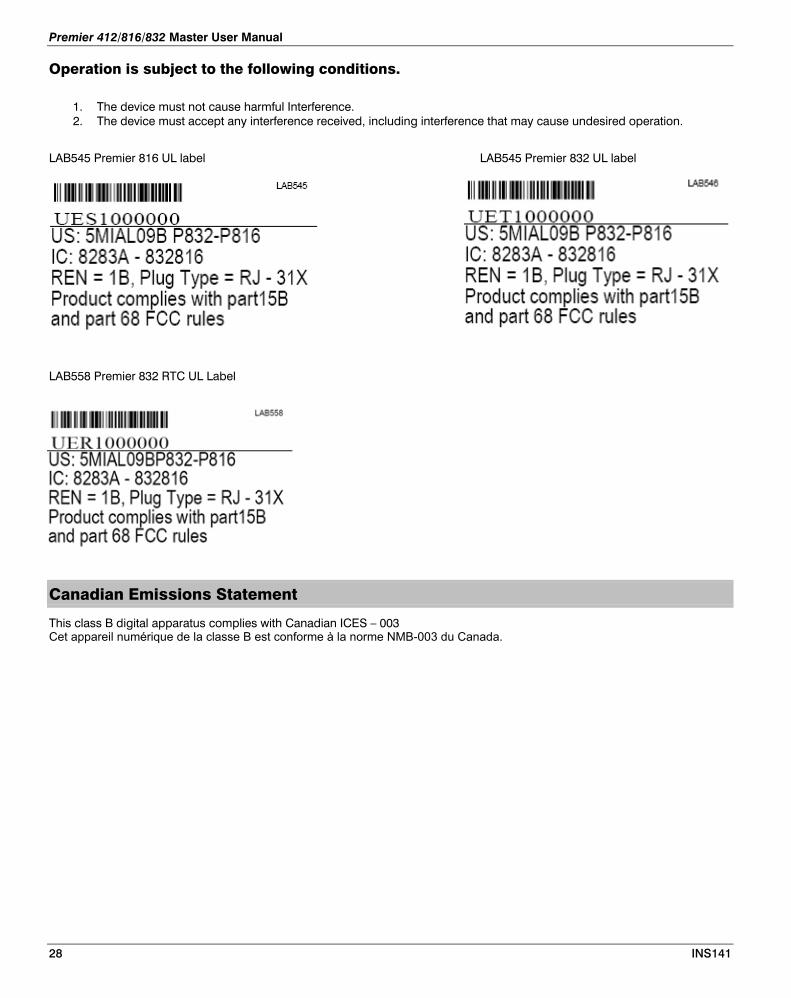
Premier 412/816/832 Master User Manual
Operation is subject to the following conditions.
1. The device must not cause harmful Interference. 2. The device must accept any interference received, including interference that may cause undesired operation.
LAB545 Premier 816 UL label LAB545 Premier 832 UL label
LAB558 Premier 832 RTC UL Label
Canadian Emissions Statement
This class B digital apparatus complies with Canadian ICES – 003 Cet appareil numérique de la classe B est conforme à la norme NMB-003 du Canada.
28 INS141
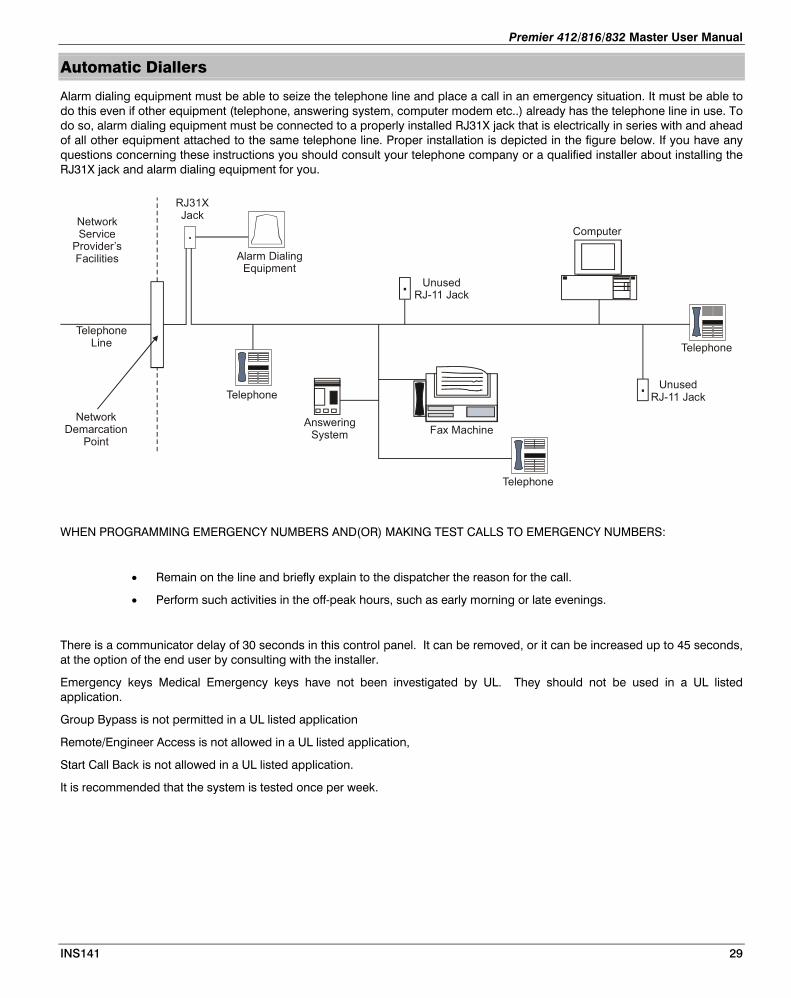
Premier 412/816/832 Master User Manual
Automatic Diallers
Alarm dialing equipment must be able to seize the telephone line and place a call in an emergency situation. It must be able to do this even if other equipment (telephone, answering system, computer modem etc..) already has the telephone line in use. To do so, alarm dialing equipment must be connected to a properly installed RJ31X jack that is electrically in series with and ahead of all other equipment attached to the same telephone line. Proper installation is depicted in the figure below. If you have any questions concerning these instructions you should consult your telephone company or a qualified installer about installing the RJ31X jack and alarm dialing equipment for you.
TelephoneLine
NetworkDemarcation
Point
Telephone
Telephone
Telephone
Fax MachineAnswering
System
Alarm DialingEquipment
RJ31XJack
UnusedRJ-11 Jack
UnusedRJ-11 Jack
NetworkService
Provider’sFacilities
Computer
WHEN PROGRAMMING EMERGENCY NUMBERS AND(OR) MAKING TEST CALLS TO EMERGENCY NUMBERS:
• Remain on the line and briefly explain to the dispatcher the reason for the call.
• Perform such activities in the off-peak hours, such as early morning or late evenings.
There is a communicator delay of 30 seconds in this control panel. It can be removed, or it can be increased up to 45 seconds, at the option of the end user by consulting with the installer.
Emergency keys Medical Emergency keys have not been investigated by UL. They should not be used in a UL listed application.
Group Bypass is not permitted in a UL listed application
Remote/Engineer Access is not allowed in a UL listed application,
Start Call Back is not allowed in a UL listed application.
It is recommended that the system is tested once per week.
INS141 29
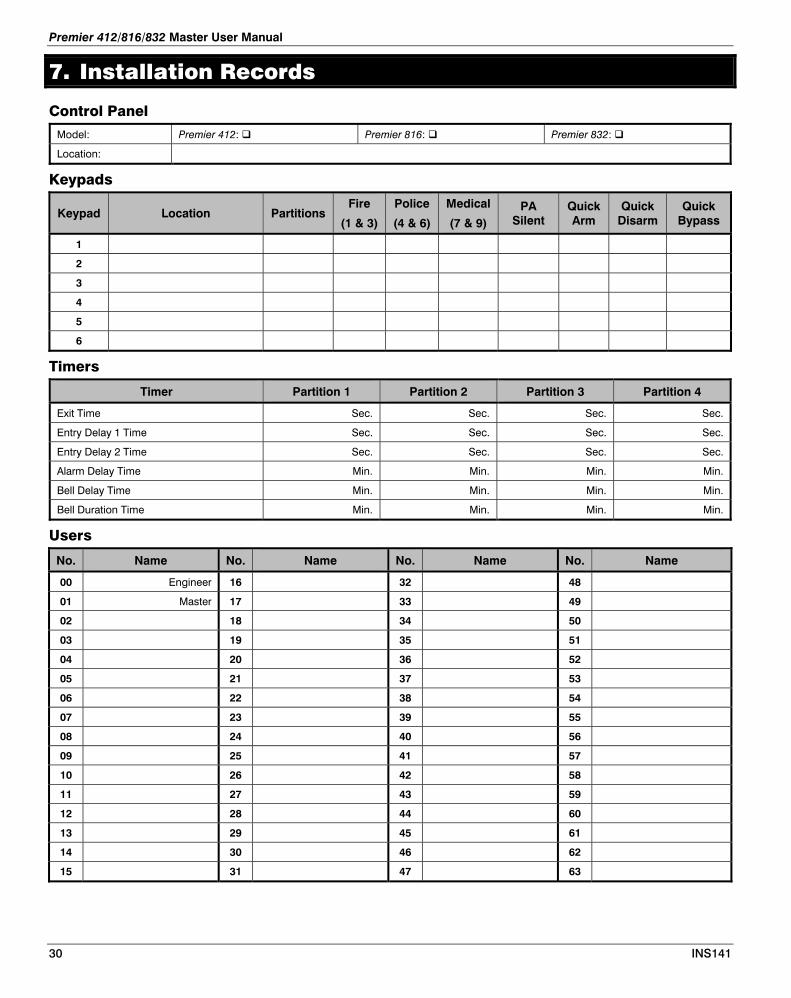
Premier 412/816/832 Master User Manual
30 INS141
7. Installation Records
Control Panel
Model: Premier 412: Premier 816: Premier 832:
Location:
Keypads
Keypad Location Partitions Fire
(1 & 3)
Police
(4 & 6)
Medical
(7 & 9) PA
Silent Quick Arm
Quick Disarm
Quick Bypass
1
2
3
4
5
6
Timers
Timer Partition 1 Partition 2 Partition 3 Partition 4
Exit Time Sec. Sec. Sec. Sec.
Entry Delay 1 Time Sec. Sec. Sec. Sec.
Entry Delay 2 Time Sec. Sec. Sec. Sec.
Alarm Delay Time Min. Min. Min. Min.
Bell Delay Time Min. Min. Min. Min.
Bell Duration Time Min. Min. Min. Min.
Users
No. Name No. Name No. Name No. Name
00 Engineer 16 32 48
01 Master 17 33 49
02 18 34 50
03 19 35 51
04 20 36 52
05 21 37 53
06 22 38 54
07 23 39 55
08 24 40 56
09 25 41 57
10 26 42 58
11 27 43 59
12 28 44 60
13 29 45 61
14 30 46 62
15 31 47 63
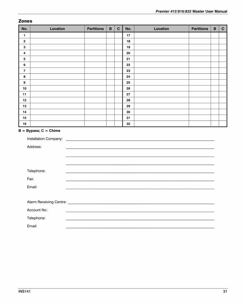
Premier 412/816/832 Master User Manual
Zones
No. Location Partitions B C No. Location Partitions B C
1 17
2 18
3 19
4 20
5 21
6 22
7 23
8 24
9 25
10 26
11 27
12 28
13 29
14 30
15 31
16 32
B = Bypass; C = Chime
Installation Company: _________________________________________________________________________________
Address: _________________________________________________________________________________
_________________________________________________________________________________
_________________________________________________________________________________
Telephone: _________________________________________________________________________________
Fax: _________________________________________________________________________________
Email: _________________________________________________________________________________
Alarm Receiving Centre: ________________________________________________________________________________
Account No: _________________________________________________________________________________
Telephone: _________________________________________________________________________________
Email: _________________________________________________________________________________
INS141 31

8. Annex A
Table 1 ANSI/SIA CP-01-2007 Requirements Section 4.7/Annex A/ 4.6.1
CP-01-2007
PARAGRAPH
FEATURE REQUIREMENT RANGE SHIPPING
DEFAULT
RECOMMENDED
PROGRAMMING *
Standard Defaults Manual INS490
4.2.2.1 Exit Time Required
(programmable)
For full or auto arming:
45 sec. - 2 min.
(255 sec. max.)
60 Seconds 60 Seconds Page 9 Default 60 Seconds
Menu Option 20
4.2.2.2 Progress Annunciation / Disable - for Silent Exit
Allowed Individual keypads may be disabled
All annunciators enabled
All annunciators enabled Page 12 all Progress Annunciators are enabled.
Menu Option 42
Page 9 Default Disabled Silent Exit
Menu Option 26.2
4.2.2.3 Exit Time Restart Required Option For re-entry during exit time
Enabled Enabled Not Programmable permanently enabled
4.2.2.5 Auto Stay Arm on Unvacated Premises
Required Option
(except for remote arm)
If no exit after full arm
Enabled Enabled Page 9 Auto Bypass Default enabled
Menu Option 26.1
4.2.4.4 Exit Time and Progress Annunciation / Disable - for Remote Arm
Allowed Option
(for remote arm)
May be disabled - for remote arming
Enabled Enabled Default for Remote arm is enabled
Page 9 Menu 26-3
4.2.3.1
Entry Delay(s) Required
(programmable)
30 sec. - 4 min. **
30 Seconds At least 30 Seconds ** Entry Delay 1 Default 30 Seconds
Entry Delay 2 Default 30 Seconds
Page 9
Menu Option 21 for Entry Delay 1
Menu Option 22 For Entry Delay 2
4.2.5.1 Abort Window – for Non-Fire Zones
Required Option May be disabled - by zone or zone type
Enabled Enabled (all zones) Enabled Transmission Delay Default Enabled.
Zone attribute Menu Option 13-7
4.2.5.1 Abort Window Time – for Non-Fire Zones
Required
(programmable)
15 sec. - 45 sec. **
30 Seconds At least 15 seconds ** Comms Delay
Default is 30 Seconds.
Page 9
Menu Option 23
4.2.5.1.2 Abort annunciation
Required Option Annunciate that no alarm was transmitted
Enabled Enabled Default Enabled
Page 12
Menu Option 43-6
32 INS141
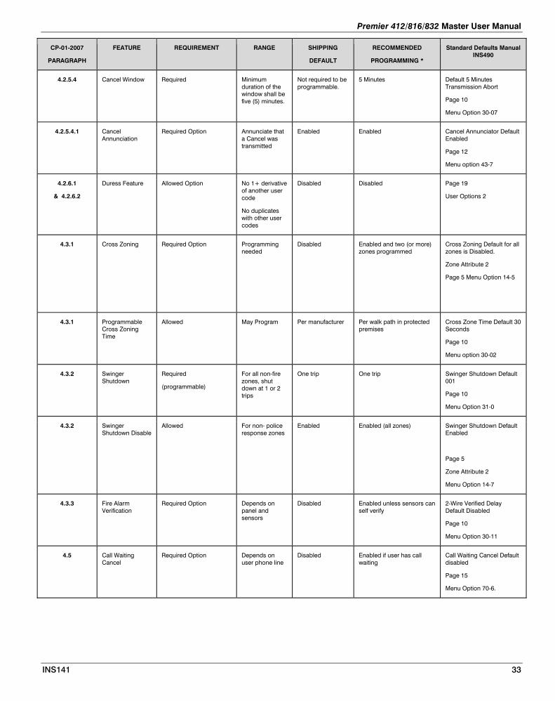
Premier 412/816/832 Master User Manual
CP-01-2007
PARAGRAPH
FEATURE REQUIREMENT RANGE SHIPPING
DEFAULT
RECOMMENDED
PROGRAMMING *
Standard Defaults Manual INS490
4.2.5.4 Cancel Window Required Minimum duration of the window shall be five (5) minutes.
Not required to be programmable.
5 Minutes Default 5 Minutes Transmission Abort
Page 10
Menu Option 30-07
4.2.5.4.1 Cancel Annunciation
Required Option Annunciate that a Cancel was transmitted
Enabled Enabled Cancel Annunciator Default Enabled
Page 12
Menu option 43-7
4.2.6.1
& 4.2.6.2
Duress Feature Allowed Option No 1+ derivative of another user code
No duplicates with other user codes
Disabled Disabled Page 19
User Options 2
4.3.1 Cross Zoning Required Option Programming needed
Disabled Enabled and two (or more) zones programmed
Cross Zoning Default for all zones is Disabled.
Zone Attribute 2
Page 5 Menu Option 14-5
4.3.1 Programmable Cross Zoning Time
Allowed May Program Per manufacturer Per walk path in protected premises
Cross Zone Time Default 30 Seconds
Page 10
Menu option 30-02
4.3.2 Swinger Shutdown
Required
(programmable)
For all non-fire zones, shut down at 1 or 2 trips
One trip One trip Swinger Shutdown Default 001
Page 10
Menu Option 31-0
4.3.2 Swinger Shutdown Disable
Allowed For non- police response zones
Enabled Enabled (all zones) Swinger Shutdown Default Enabled
Page 5
Zone Attribute 2
Menu Option 14-7
4.3.3 Fire Alarm Verification
Required Option Depends on panel and sensors
Disabled Enabled unless sensors can self verify
2-Wire Verified Delay Default Disabled
Page 10
Menu Option 30-11
4.5 Call Waiting Cancel
Required Option Depends on user phone line
Disabled Enabled if user has call waiting
Call Waiting Cancel Default disabled
Page 15
Menu Option 70-6.
INS141 33

Premier 412/816/832 Master User Manual
34 INS141
Minimum system requirements for Classification in accordance with ANSI/SIA CP-01-2007
1. UL Listed and Classified control unit Model Premier 816 or Premier 832, or Premier 832 Real Time Clock;
2. UL Listed and Classified keypad Model Premier LCDL-P, or Premier FMK Elite, or Premier SMK Elite;
3. UL Listed Local Bell.

Premier 412/816/832 Master User Manual
Notes
INS141 35

Texecom Ltd
Bradwood Court, St Crispin Way, Haslingden
Lancashire BB4 4PW
United Kingdom