Master Notation SHeet
19
Notation Originally drafted by Brian Faulkner. Last updated 8/11/2017 by C. D. Schmitz Everything is in SI units http://en.wikipedia.org/wiki/SI_derived_unit When variables and units are together in the same equation/expression, the equation is in italics, but the unit is in non-italics. For example, Vb=10 mV Use Microsoft’s equation editor for all symbols and values and units. The VISIO Template: When using the VISIO template created for ECE110, size matters. Most symbols are constructed to span a space of 1.5 inches between terminal ends. It generally provides sufficient spacing for labels without being excessive. Most figures are saved and used 1:1 in scale, but the final diagram may be scaled when the size is difficult to work with. Vertical and horizontal connectors may be used as interconnecting wires when needed. When additional space between symbols is required, increase spacing using the vertical or horizontal connectors in distances of 0.25 inches. Vocabulary Common terms used in ECE110: source and load (sub-circuits) deliver and absorb (power) Term Similar terms Definition Notes load sink A device generally expected to absorb power. load preferred absorb dissipate The transformation of electrical energy into another form such as heat or EM waves. absorb preferred deliver generate, produce To transform nonelectrical forms of energy (mechanical, solar, or chemical, for example), into electrical energy. deliver preferred generate deliver, produce not used. deliver preferred produce deliver, generate Same as deliver. deliver preferred
Transcript of Master Notation SHeet

Notation Originally drafted by Brian Faulkner. Last updated 8/11/2017 by C. D. Schmitz
Everything is in SI units http://en.wikipedia.org/wiki/SI_derived_unit
When variables and units are together in the same equation/expression, the equation is in
italics, but the unit is in non-italics. For example, Vb=10 mV
Use Microsoft’s equation editor for all symbols and values and units.
The VISIO Template:
When using the VISIO template created for ECE110, size matters. Most symbols are constructed to span
a space of 1.5 inches between terminal ends. It generally provides sufficient spacing for labels without
being excessive. Most figures are saved and used 1:1 in scale, but the final diagram may be scaled when
the size is difficult to work with.
Vertical and horizontal connectors may be used as interconnecting wires when needed. When additional
space between symbols is required, increase spacing using the vertical or horizontal connectors in
distances of 0.25 inches.
Vocabulary
Common terms used in ECE110:
source and load (sub-circuits)
deliver and absorb (power)
Term Similar
terms Definition Notes
load sink A device generally expected to absorb
power. load preferred
absorb dissipate The transformation of electrical energy
into another form such as heat or EM
waves.
absorb preferred
deliver generate,
produce To transform nonelectrical forms of
energy (mechanical, solar, or chemical,
for example), into electrical energy.
deliver preferred
generate deliver,
produce not used. deliver preferred
produce deliver,
generate Same as deliver. deliver preferred
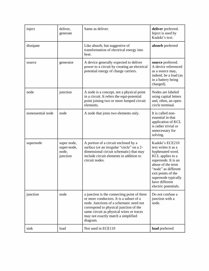
inject deliver,
generate Same as deliver. deliver preferred.
Inject is used by
Kudeki’s text.
dissipate Like absorb, but suggestive of
transformation of electrical energy into
heat.
absorb preferred
source generator A device generally expected to deliver
power to a circuit by creating an electrical
potential energy of charge carriers.
source preferred. A device referenced
as a source may,
indeed, be a load (as
in a battery being
charged).
node junction A node is a concept, not a physical point
in a circuit. It refers the equi-potential
point joining two or more lumped circuit
elements.
Nodes are labeled
using capital letters
and, often, an open-
circle terminal.
nonessential node node A node that joins two elements only. It is called non-
essential in that
application of KCL
is rather trivial or
unnecessary for
solving.
supernode super node,
super-node,
node,
junction
A portion of a circuit enclosed by a
surface (or an irregular “circle” on a 2-
dimensional circuit schematic) that may
include circuit elements in addition to
circuit nodes.
Kudeki’s ECE210
text writes it as a
hyphenated word.
KCL applies to a
supernode. It is an
abuse of the term
“node” as different
exit points of the
supernode typically
have different
electric potentials.
junction node a junction is the connecting point of three
or more conductors. It is a subset of a
node. Junctions of a schematic need not
correspond to physical junction of the
same circuit as physical wires or traces
may not exactly match a simplified
diagram.
Do not confuse a
junction with a
node.
sink load Not used in ECE110 load preferred
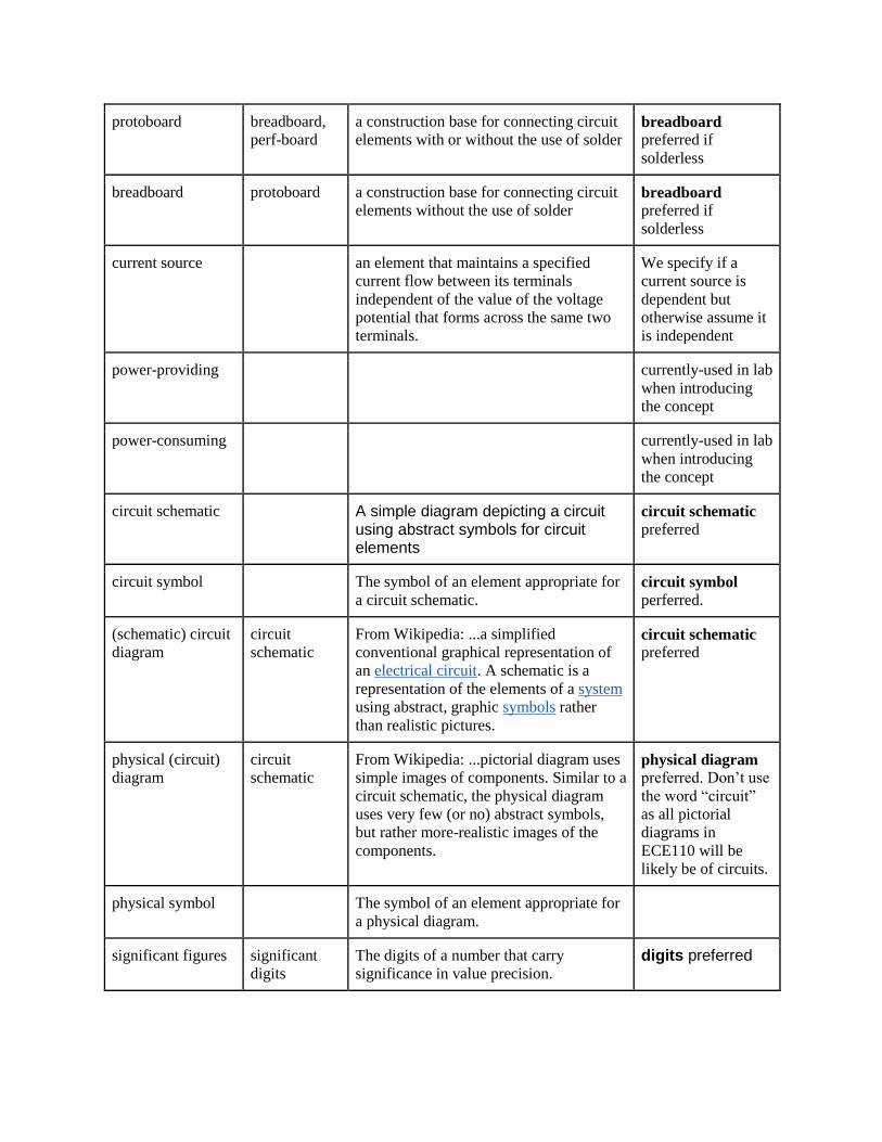
protoboard breadboard,
perf-board a construction base for connecting circuit
elements with or without the use of solder breadboard
preferred if
solderless
breadboard protoboard a construction base for connecting circuit
elements without the use of solder breadboard
preferred if
solderless
current source an element that maintains a specified
current flow between its terminals
independent of the value of the voltage
potential that forms across the same two
terminals.
We specify if a
current source is
dependent but
otherwise assume it
is independent
power-providing currently-used in lab
when introducing
the concept
power-consuming currently-used in lab
when introducing
the concept
circuit schematic A simple diagram depicting a circuit using abstract symbols for circuit elements
circuit schematic
preferred
circuit symbol The symbol of an element appropriate for
a circuit schematic. circuit symbol
perferred.
(schematic) circuit
diagram circuit
schematic From Wikipedia: ...a simplified
conventional graphical representation of
an electrical circuit. A schematic is a
representation of the elements of a system
using abstract, graphic symbols rather
than realistic pictures.
circuit schematic
preferred
physical (circuit)
diagram circuit
schematic From Wikipedia: ...pictorial diagram uses
simple images of components. Similar to a
circuit schematic, the physical diagram
uses very few (or no) abstract symbols,
but rather more-realistic images of the
components.
physical diagram
preferred. Don’t use
the word “circuit”
as all pictorial
diagrams in
ECE110 will be
likely be of circuits.
physical symbol The symbol of an element appropriate for
a physical diagram.
significant figures significant
digits The digits of a number that carry
significance in value precision. digits preferred
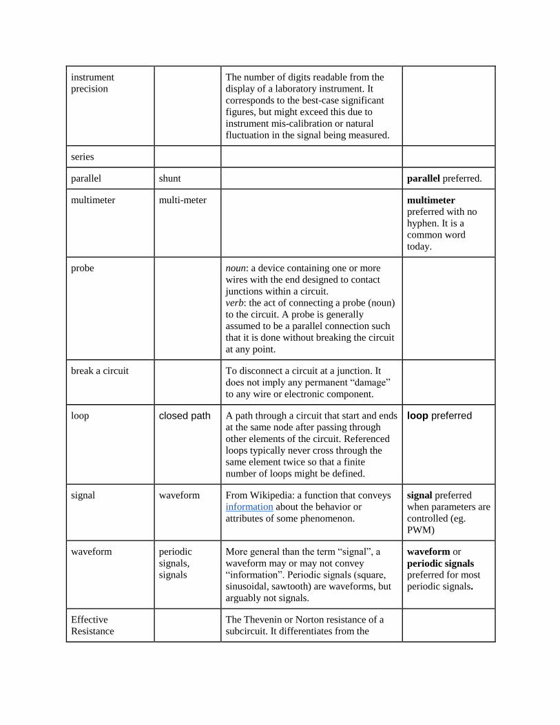
instrument
precision The number of digits readable from the
display of a laboratory instrument. It
corresponds to the best-case significant
figures, but might exceed this due to
instrument mis-calibration or natural
fluctuation in the signal being measured.
series
parallel shunt parallel preferred.
multimeter multi-meter multimeter
preferred with no
hyphen. It is a
common word
today.
probe noun: a device containing one or more
wires with the end designed to contact
junctions within a circuit. verb: the act of connecting a probe (noun)
to the circuit. A probe is generally
assumed to be a parallel connection such
that it is done without breaking the circuit
at any point.
break a circuit To disconnect a circuit at a junction. It
does not imply any permanent “damage”
to any wire or electronic component.
loop closed path A path through a circuit that start and ends
at the same node after passing through
other elements of the circuit. Referenced
loops typically never cross through the
same element twice so that a finite
number of loops might be defined.
loop preferred
signal waveform From Wikipedia: a function that conveys
information about the behavior or
attributes of some phenomenon.
signal preferred
when parameters are
controlled (eg.
PWM)
waveform periodic
signals,
signals
More general than the term “signal”, a
waveform may or may not convey
“information”. Periodic signals (square,
sinusoidal, sawtooth) are waveforms, but
arguably not signals.
waveform or
periodic signals
preferred for most
periodic signals.
Effective
Resistance The Thevenin or Norton resistance of a
subcircuit. It differentiates from the
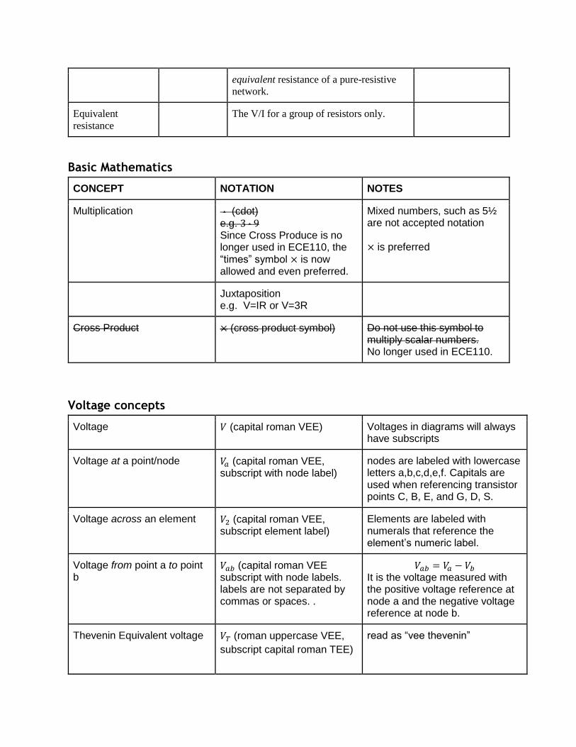
equivalent resistance of a pure-resistive
network.
Equivalent
resistance The V/I for a group of resistors only.
Basic Mathematics
CONCEPT NOTATION NOTES
Multiplication ⋅ (cdot) e.g. 3 ⋅ 9 Since Cross Produce is no longer used in ECE110, the “times” symbol × is now allowed and even preferred.
Mixed numbers, such as 5½ are not accepted notation
× is preferred
Juxtaposition e.g. V=IR or V=3R
Cross Product × (cross product symbol) Do not use this symbol to multiply scalar numbers. No longer used in ECE110.
Voltage concepts
Voltage 𝑉 (capital roman VEE) Voltages in diagrams will always have subscripts
Voltage at a point/node 𝑉𝑎 (capital roman VEE, subscript with node label)
nodes are labeled with lowercase letters a,b,c,d,e,f. Capitals are used when referencing transistor points C, B, E, and G, D, S.
Voltage across an element 𝑉2 (capital roman VEE, subscript element label)
Elements are labeled with numerals that reference the element’s numeric label.
Voltage from point a to point b
𝑉𝑎𝑏 (capital roman VEE subscript with node labels. labels are not separated by commas or spaces. .
𝑉𝑎𝑏 = 𝑉𝑎 − 𝑉𝑏 It is the voltage measured with the positive voltage reference at node a and the negative voltage reference at node b.
Thevenin Equivalent voltage 𝑉𝑇 (roman uppercase VEE,
subscript capital roman TEE)
read as “vee thevenin”

Diode on voltage 𝑉𝑜𝑛 (uppercase roman VEE,
subscript lowercase roman
oh enn)
read as “vee on”
Ideal Voltage source
(open circle with wires
emerging, both a + and - sign
indicating orientation
ECE110 has not had a need for a dependent voltage source and (non-ideal) batteries are specifically represented by a different symbol. Therefore, simply voltage source is preferred.
Battery
(big line small line big line small line)
Always means actually a battery. May or may not be adequately modeled by an ideal source. Students should assume non-ideal qualities should be considered. When turned horizontal, the negative sign should be rotated to remain horizontal.
Cell
(big line small line with + and - labels)
Single-cell alkaline typically
measure around 1.5 𝑉 while single-cell NiMH 1.2 𝑉.
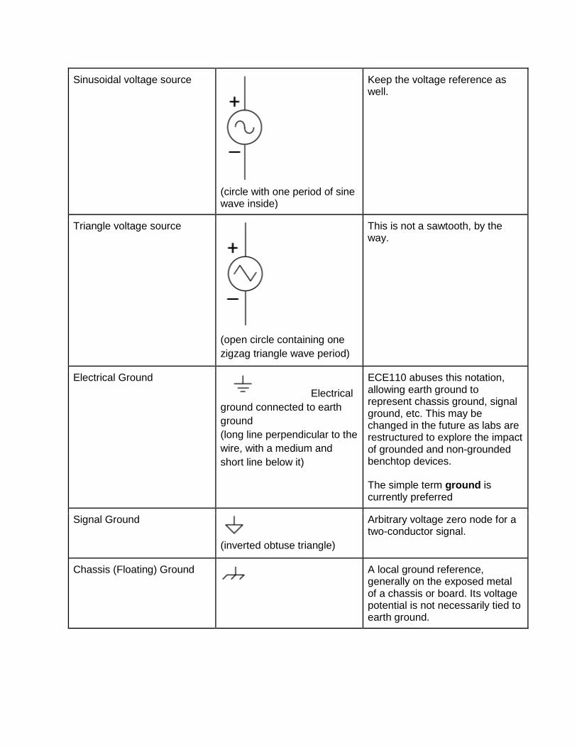
Sinusoidal voltage source
(circle with one period of sine wave inside)
Keep the voltage reference as well.
Triangle voltage source
(open circle containing one
zigzag triangle wave period)
This is not a sawtooth, by the way.
Electrical Ground
Electrical
ground connected to earth
ground
(long line perpendicular to the
wire, with a medium and
short line below it)
ECE110 abuses this notation, allowing earth ground to represent chassis ground, signal ground, etc. This may be changed in the future as labs are restructured to explore the impact of grounded and non-grounded benchtop devices. The simple term ground is currently preferred
Signal Ground
(inverted obtuse triangle)
Arbitrary voltage zero node for a two-conductor signal.
Chassis (Floating) Ground
A local ground reference, generally on the exposed metal of a chassis or board. Its voltage potential is not necessarily tied to earth ground.
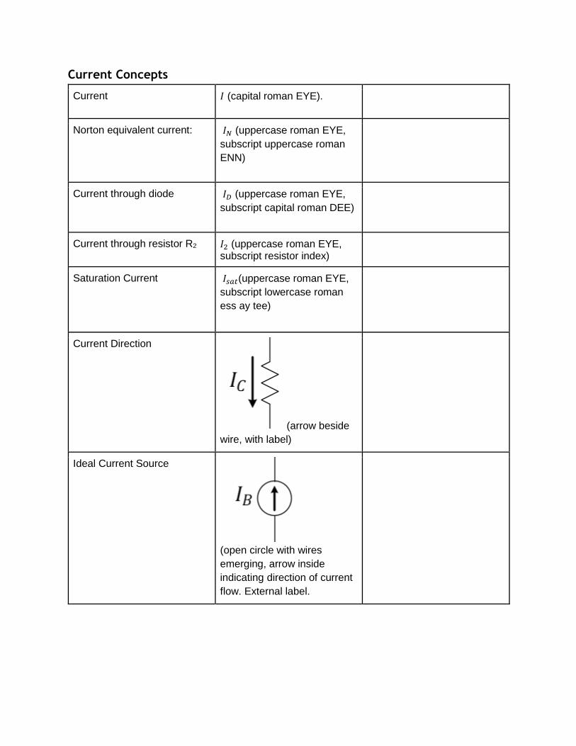
Current Concepts
Current 𝐼 (capital roman EYE).
Norton equivalent current: 𝐼𝑁 (uppercase roman EYE,
subscript uppercase roman
ENN)
Current through diode 𝐼𝐷 (uppercase roman EYE,
subscript capital roman DEE)
Current through resistor R2 𝐼2 (uppercase roman EYE, subscript resistor index)
Saturation Current 𝐼𝑠𝑎𝑡(uppercase roman EYE,
subscript lowercase roman
ess ay tee)
Current Direction
(arrow beside
wire, with label)
Ideal Current Source
(open circle with wires
emerging, arrow inside
indicating direction of current
flow. External label.

dependent current source
(diamond with arrow),
external label.
Resistance Concepts
Resistance 𝑅1 (uppercase roman ARE) Elements are labeled with numerals that reference the element’s numeric label.
Equivalent Resistance 𝑅𝑒𝑞 (uppercase roman ARE,
subscript lowercase roman eee and lowercase roman que)
Used for purely resistive networks.
Effective Resistance 𝑅𝑒𝑓𝑓 (uppercase roman ARE,
subscript lowercase roman eee and lowercase roman eff eff)
Used for mixed networks, but equivalent to Thevenin and Norton resistances.
Thevenin equivalent resistance
𝑅𝑇 (uppercase roman ARE,
subscript uppercase roman
TEE)
Norton equivalent resistance 𝑅𝑁 (uppercase roman ARE,
subscript uppercase roman
ENN)
In series with + (plus sign)
in the expression R1||R2+R3, || operates first, + operates second
In parallel with || (two pipes) Used in the online textbook in
Circuit Shortcuts and often
used by the lecturers during
class time.
Resistivity: ρ (lowercase greek rho)
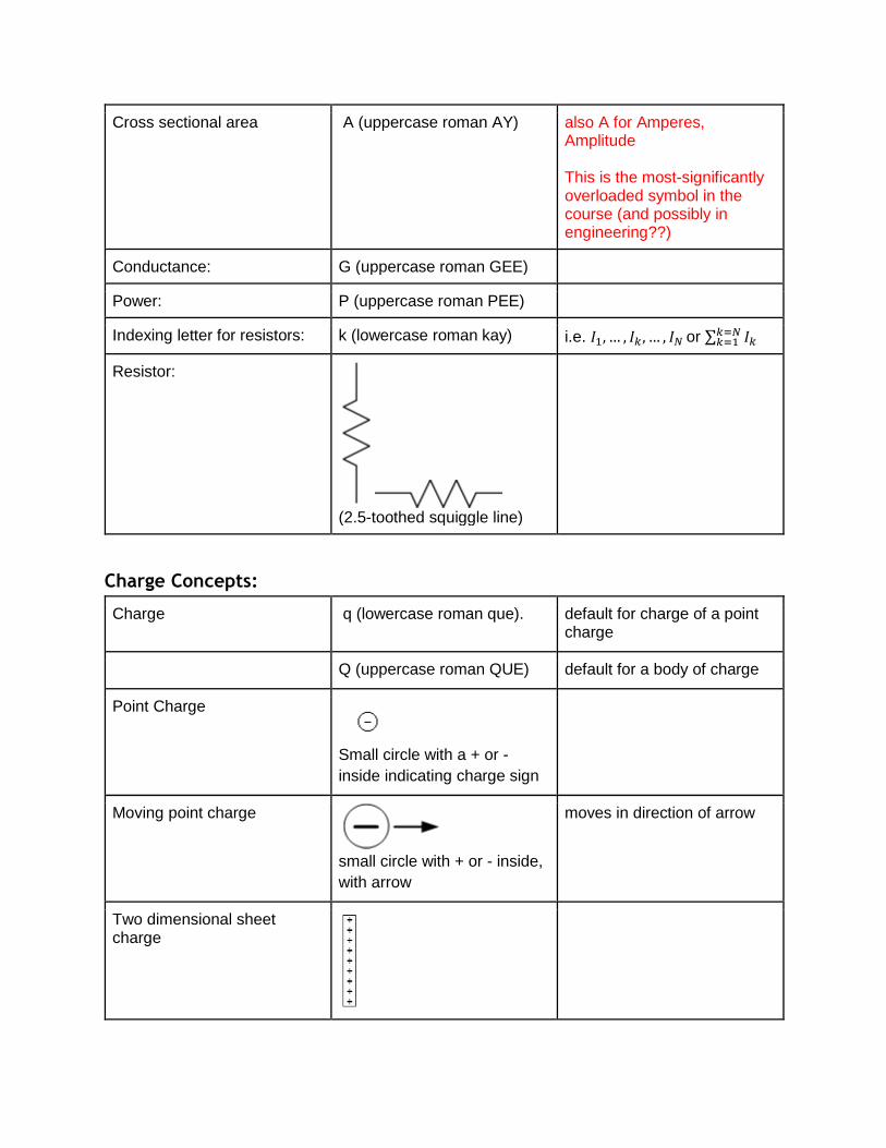
Cross sectional area A (uppercase roman AY) also A for Amperes, Amplitude This is the most-significantly overloaded symbol in the course (and possibly in engineering??)
Conductance: G (uppercase roman GEE)
Power: P (uppercase roman PEE)
Indexing letter for resistors: k (lowercase roman kay) i.e. 𝐼1, … , 𝐼𝑘, … , 𝐼𝑁 or ∑ 𝐼𝑘𝑘=𝑁𝑘=1
Resistor:
(2.5-toothed squiggle line)
Charge Concepts:
Charge q (lowercase roman que).
default for charge of a point charge
Q (uppercase roman QUE) default for a body of charge
Point Charge
Small circle with a + or -
inside indicating charge sign
Moving point charge
small circle with + or - inside,
with arrow
moves in direction of arrow
Two dimensional sheet charge
rectangle with many +’s or -’s inside
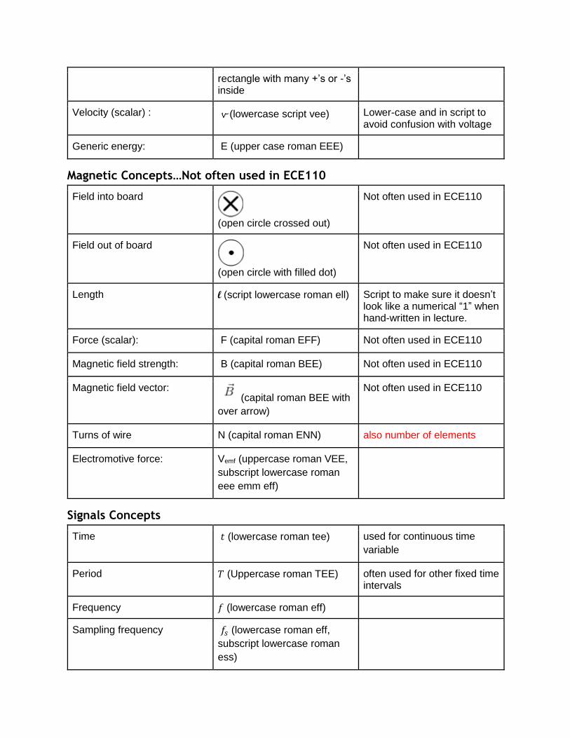
Velocity (scalar) : v (lowercase script vee) Lower-case and in script to avoid confusion with voltage
Generic energy: E (upper case roman EEE)
Magnetic Concepts…Not often used in ECE110
Field into board
(open circle crossed out)
Not often used in ECE110
Field out of board
(open circle with filled dot)
Not often used in ECE110
Length l (script lowercase roman ell) Script to make sure it doesn’t look like a numerical “1” when hand-written in lecture.
Force (scalar): F (capital roman EFF) Not often used in ECE110
Magnetic field strength: B (capital roman BEE) Not often used in ECE110
Magnetic field vector: (capital roman BEE with
over arrow)
Not often used in ECE110
Turns of wire N (capital roman ENN) also number of elements
Electromotive force: Vemf (uppercase roman VEE,
subscript lowercase roman
eee emm eff)
Signals Concepts
Time 𝑡 (lowercase roman tee) used for continuous time
variable
Period 𝑇 (Uppercase roman TEE) often used for other fixed time intervals
Frequency 𝑓 (lowercase roman eff)
Sampling frequency 𝑓𝑠 (lowercase roman eff,
subscript lowercase roman
ess)
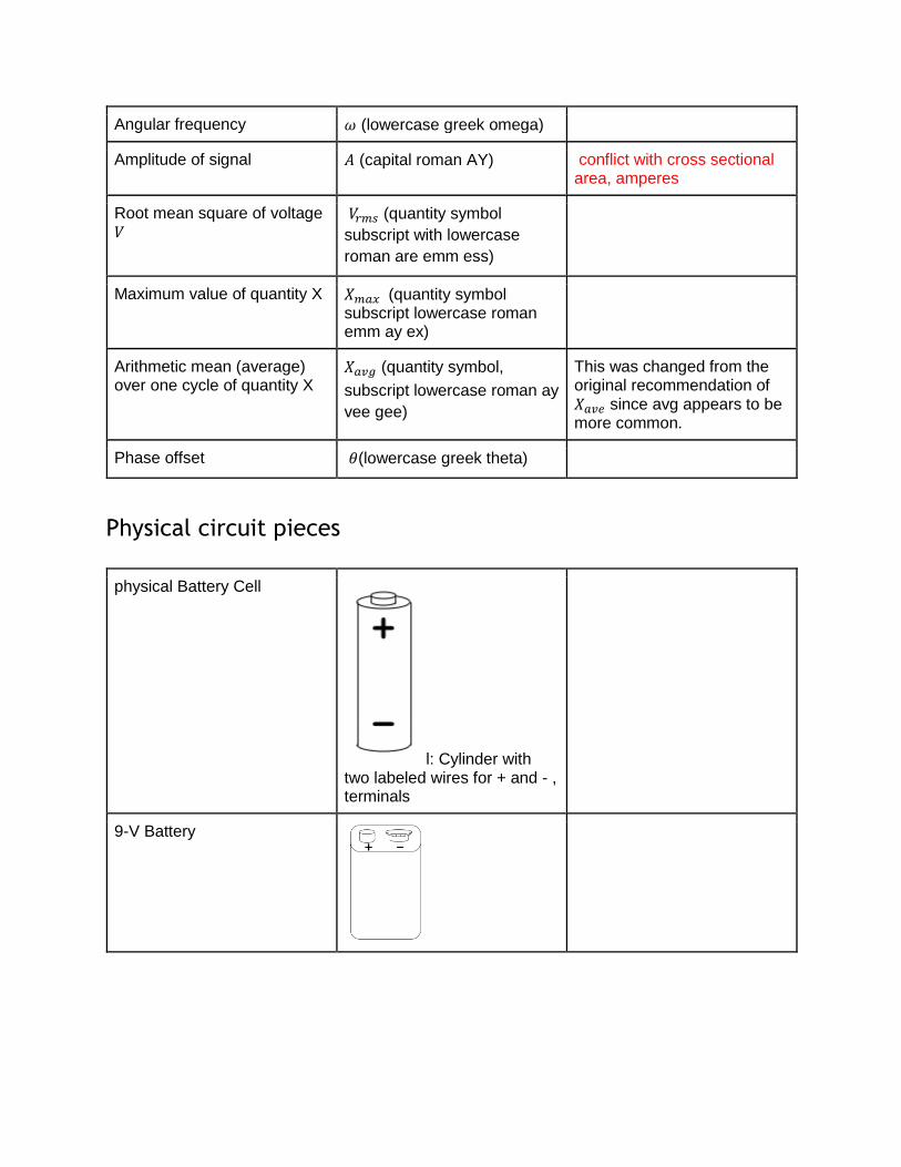
Angular frequency 𝜔 (lowercase greek omega)
Amplitude of signal 𝐴 (capital roman AY) conflict with cross sectional area, amperes
Root mean square of voltage 𝑉
𝑉𝑟𝑚𝑠 (quantity symbol
subscript with lowercase
roman are emm ess)
Maximum value of quantity X 𝑋𝑚𝑎𝑥 (quantity symbol subscript lowercase roman emm ay ex)
Arithmetic mean (average) over one cycle of quantity X
𝑋𝑎𝑣𝑔 (quantity symbol,
subscript lowercase roman ay
vee gee)
This was changed from the original recommendation of 𝑋𝑎𝑣𝑒 since avg appears to be more common.
Phase offset 𝜃(lowercase greek theta)
Physical circuit pieces
physical Battery Cell
l: Cylinder with two labeled wires for + and - , terminals
9-V Battery
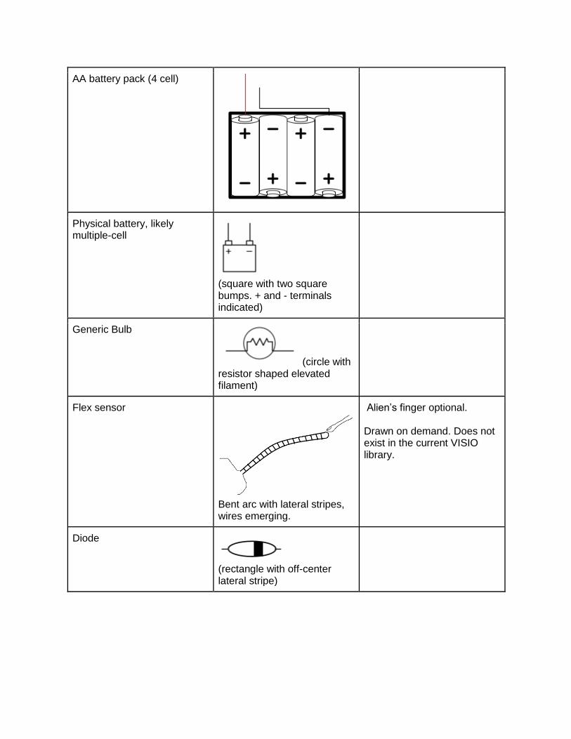
AA battery pack (4 cell)
Physical battery, likely multiple-cell
(square with two square bumps. + and - terminals indicated)
Generic Bulb
(circle with resistor shaped elevated filament)
Flex sensor
Bent arc with lateral stripes, wires emerging.
Alien’s finger optional. Drawn on demand. Does not exist in the current VISIO library.
Diode
(rectangle with off-center lateral stripe)
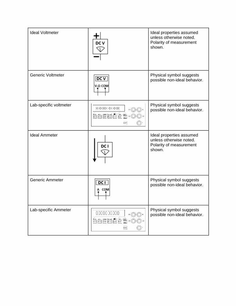
Ideal Voltmeter
Ideal properties assumed unless otherwise noted. Polarity of measurement shown.
Generic Voltmeter
Physical symbol suggests possible non-ideal behavior.
Lab-specific voltmeter
Physical symbol suggests possible non-ideal behavior.
Ideal Ammeter
Ideal properties assumed unless otherwise noted. Polarity of measurement shown.
Generic Ammeter
Physical symbol suggests possible non-ideal behavior.
Lab-specific Ammeter
Physical symbol suggests possible non-ideal behavior.
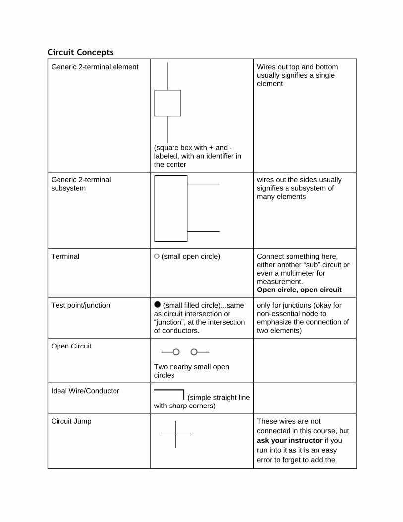
Circuit Concepts
Generic 2-terminal element
(square box with + and - labeled, with an identifier in the center
Wires out top and bottom usually signifies a single element
Generic 2-terminal subsystem
wires out the sides usually signifies a subsystem of many elements
Terminal (small open circle) Connect something here, either another “sub” circuit or even a multimeter for measurement. Open circle, open circuit
Test point/junction (small filled circle)...same as circuit intersection or “junction”, at the intersection of conductors.
only for junctions (okay for non-essential node to emphasize the connection of two elements)
Open Circuit
Two nearby small open circles
Ideal Wire/Conductor (simple straight line
with sharp corners)
Circuit Jump
These wires are not
connected in this course, but
ask your instructor if you
run into it as it is an easy
error to forget to add the
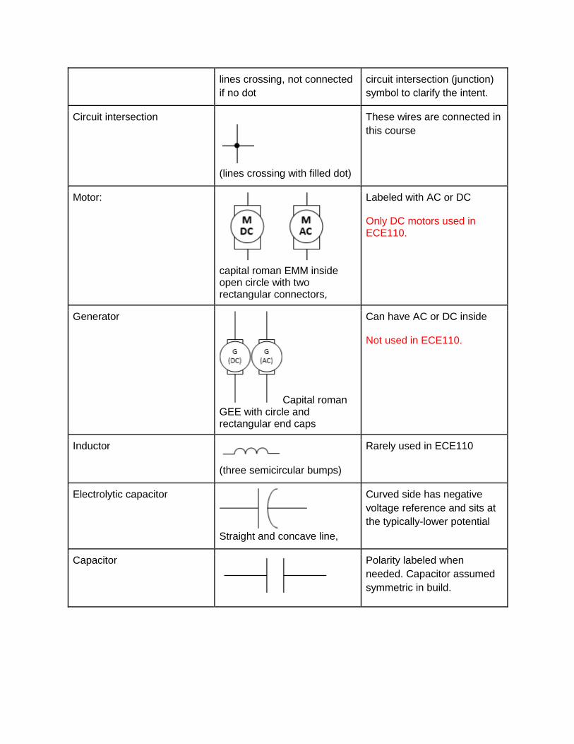
lines crossing, not connected
if no dot
circuit intersection (junction)
symbol to clarify the intent.
Circuit intersection
(lines crossing with filled dot)
These wires are connected in
this course
Motor:
capital roman EMM inside open circle with two rectangular connectors,
Labeled with AC or DC Only DC motors used in ECE110.
Generator
Capital roman GEE with circle and rectangular end caps
Can have AC or DC inside Not used in ECE110.
Inductor
(three semicircular bumps)
Rarely used in ECE110
Electrolytic capacitor
Straight and concave line,
Curved side has negative
voltage reference and sits at
the typically-lower potential
Capacitor
Polarity labeled when
needed. Capacitor assumed
symmetric in build.
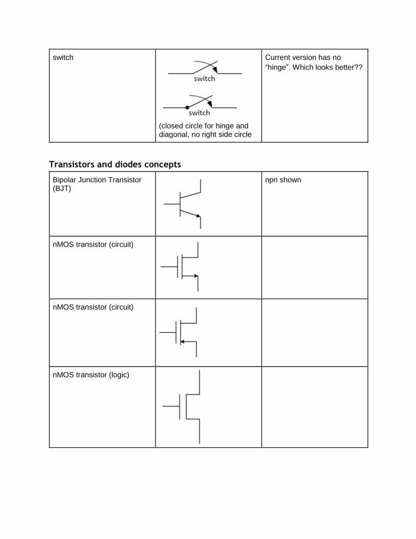
switch
(closed circle for hinge and diagonal, no right side circle
Current version has no
“hinge”. Which looks better??
Transistors and diodes concepts
Bipolar Junction Transistor (BJT)
npn shown
nMOS transistor (circuit)
nMOS transistor (circuit)
nMOS transistor (logic)
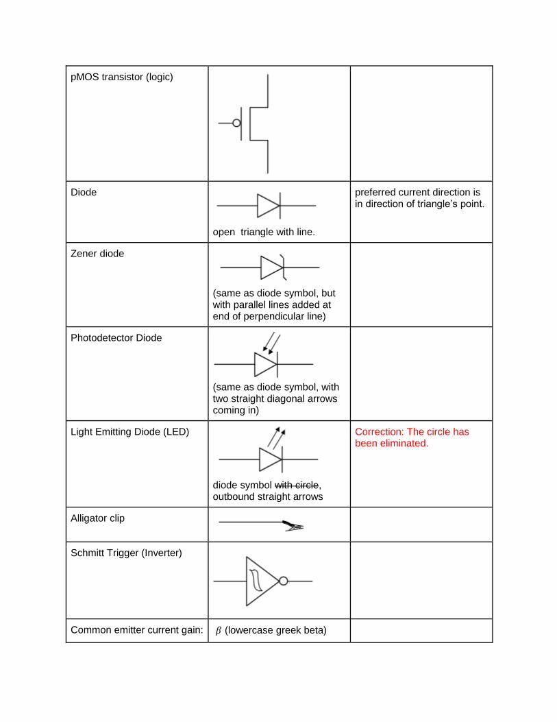
pMOS transistor (logic)
Diode
open triangle with line.
preferred current direction is in direction of triangle’s point.
Zener diode
(same as diode symbol, but with parallel lines added at end of perpendicular line)
Photodetector Diode
(same as diode symbol, with two straight diagonal arrows coming in)
Light Emitting Diode (LED)
diode symbol with circle, outbound straight arrows
Correction: The circle has been eliminated.
Alligator clip
Schmitt Trigger (Inverter)
Common emitter current gain: 𝛽 (lowercase greek beta)
AC Voltage Gain 𝐺𝑉 (Capital roman GEE,
subscript capital roman VEE)


![Identifier Namespaces in Mathematical Notation · Identifier Namespaces in Mathematical Notation Master Thesis by ... and it is called mathematical notation [5]. Because of the notation,](https://static.fdocuments.net/doc/165x107/60218b2460d1022953223c94/identifier-namespaces-in-mathematical-notation-identifier-namespaces-in-mathematical.jpg)