Master Logic - Experion PKS Integration · The MasterLogic PLC-Experion integration solution...
148
Honeywell Process Solutions MasterLogic-Experion Integration User's Guide R400 March 2011 Release R400 Honeywell
Transcript of Master Logic - Experion PKS Integration · The MasterLogic PLC-Experion integration solution...

Honeywell Process Solutions
MasterLogic-Experion Integration User's Guide
R400
March 2011
Release R400 Honeywell

ii MasterLogic-Experion Integration User's Guide R400 Honeywell March 2011
Notices and Trademarks Copyright 2011 by Honeywell International Inc.
Release R400 – March 2011
While this information is presented in good faith and believed to be accurate, Honeywell disclaims the implied warranties of merchantability and fitness for a particular purpose and makes no express warranties except as may be stated in its written agreement with and for its customers.
In no event is Honeywell liable to anyone for any indirect, special or consequential damages. The information and specifications in this document are subject to change without notice.
Experion PKS is a registered trademark of Honeywell International Inc.
Other brand or product names are trademarks of their respective owners.
Honeywell Process Solutions
1860 W. Rose Garden Lane
Phoenix, AZ 85027 USA
1-800 822-7673
R400 MasterLogic-Experion Integration User's Guide iii March 2011 Honeywell
About This Document This document describes how to integrate the MasterLogic 200R/200 IEC with Experion Process Knowledge System. The guide describes the installation, configuration, operations, and troubleshooting tasks associated with the MasterLogic PLC - Experion integration. The term PLC used throughout this document refers to MasterLogic PLC. The MasterLogic PLC - Experion integration discussed in this guide is tested with ML200 IEC / ML200R and Experion R400.
Intended Audience The intended audiences for this guide include:
• Project Engineers.
• Operators.
• Service Engineers.
Prerequisites for using this guide Before you begin, ensure that you are familiar with the following information.
• Experion concepts and Quick Builder usage
REFERENCE – EXTERNAL
• For details about Experion, see Experion Knowledge Builder > Experion PKS R400 > Purpose > Overview > Introduction > Experion Process Knowledge System.
• For details about Quick Builder features and operations, see Experion Knowledge Builder > Experion PKS R400> Configuration > Quick Builder Guide.
• PLC concepts and SoftMaster tool usage.
REFERENCE - EXTERNAL
For details about PLC concepts and SoftMaster tool usage, see SoftMaster User Guide and PLC User Guide.

About This Document How to use this guide
iv MasterLogic-Experion Integration User's Guide R400 Honeywell March 2011
How to use this guide Here is a list of topics covered in this guide:
Topic
Introduction Installing ML Server MLServer License Configuration Troubleshooting
References The following list identifies references for material discussed in this publication:
Experion Knowledge Builder

About This Document Acronyms and Definitions
R400 MasterLogic-Experion Integration User's Guide v March 2011 Honeywell
Acronyms and Definitions The following section describes some commonly used industry-wide and Honeywell-specific terminology:
Terminology Description
MLServer MasterLogic Server software which interfaces MasterLogic PLC with Experion.
MLPLC MasterLogic Programmable Logic Controller.
PLC Programmable Logic Controller.
PV Process variable parameter of a standard Point.
QDB Quick Builder project file containing one or more Channels, Controllers and Points.
SM SoftMaster PLC monitoring tool.
MLDP MasterLogic Dedicated Protocol supported by ML200/ML200R.
RTC Real Time Clock data represents the current time in the PLC.
SP Set point parameter for the Experion Analog point.
OP Output parameter for the Experion Analog / Status point.
SCADA Supervisory Control and Data Acquisition
About This Document Contacts
vi MasterLogic-Experion Integration User's Guide R400 Honeywell March 2011
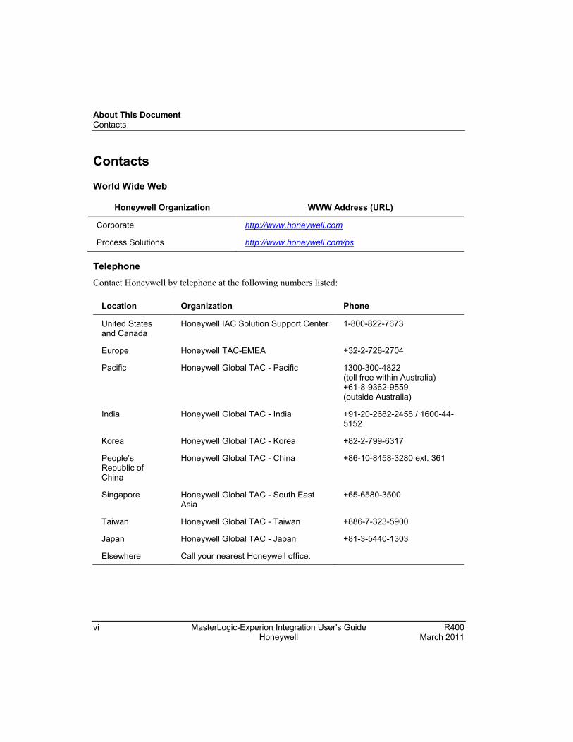
Contacts
World Wide Web
Honeywell Organization WWW Address (URL)
Corporate http://www.honeywell.com
Process Solutions http://www.honeywell.com/ps
Telephone Contact Honeywell by telephone at the following numbers listed:
Location Organization Phone
United States and Canada
Honeywell IAC Solution Support Center 1-800-822-7673
Europe Honeywell TAC-EMEA +32-2-728-2704
Pacific Honeywell Global TAC - Pacific 1300-300-4822 (toll free within Australia) +61-8-9362-9559 (outside Australia)
India Honeywell Global TAC - India +91-20-2682-2458 / 1600-44-5152
Korea Honeywell Global TAC - Korea +82-2-799-6317
People’s Republic of China
Honeywell Global TAC - China +86-10-8458-3280 ext. 361
Singapore Honeywell Global TAC - South East Asia
+65-6580-3500
Taiwan Honeywell Global TAC - Taiwan +886-7-323-5900
Japan Honeywell Global TAC - Japan +81-3-5440-1303
Elsewhere Call your nearest Honeywell office.

About This Document Symbol Definitions
R400 MasterLogic-Experion Integration User's Guide vii March 2011 Honeywell
Symbol Definitions The following table lists the symbols used in this document to denote certain conditions:
Symbol Definition
ATTENTION: Identifies information that requires special consideration.
TIP: Identifies advice or hints for the user, often in terms of performing a task.
REFERENCE -EXTERNAL: Identifies an additional source of information outside of the bookset.
REFERENCE - INTERNAL: Identifies an additional source of information within the bookset.
CAUTION: Indicates a situation which, if not avoided, may result in work (data) on the system being damaged or lost, or may result in the inability to properly perform the process.
WARNING: Indicates a potentially hazardous situation, which, if not avoided, could result in serious injury or death.

About This Document Symbol Definitions
viii MasterLogic-Experion Integration User's Guide R400 Honeywell March 2011

R400 MasterLogic-Experion Integration User's Guide ix March 2011 Honeywell
Contents
1. INTRODUCTION .......................................................................... 13
1.1 Overview ........................................................................................................ 13 MasterLogic PLC - Experion integration solution ................................................................. 13 Integration scope .................................................................................................................. 14 MasterLogic PLC-Experion integration elements ................................................................. 15 Supported MasterLogic PLCs .............................................................................................. 19
2. INSTALLING ML SERVER .......................................................... 21
2.1 Installing ML Server in Experion Server ..................................................... 21 MLServer media ................................................................................................................... 21 Installing MLServer .............................................................................................................. 21 Verifying MLServer installation ............................................................................................. 23
2.2 Installing in Client machines ........................................................................ 27 Overview .............................................................................................................................. 27 Prerequisites for installing MLServer .................................................................................... 27 MLServer media ................................................................................................................... 27 Installing MLServer .............................................................................................................. 27 Verifying MLServer installation ............................................................................................. 29
2.3 Getting started ............................................................................................... 30 Configuring MasterLogic PLC - Experion integration ........................................................... 30
2.4 Removing MLServer ..................................................................................... 31 Using Add/Remove programs .............................................................................................. 31 Using MLServer.exe in the installation CD ........................................................................... 32
2.5 Repairing MLServer ...................................................................................... 33 Using MLServer.exe in the installation CD ........................................................................... 33
3. MLSERVER LICENSE ................................................................. 35
3.1 Overview ........................................................................................................ 35 Background .......................................................................................................................... 35 Before you begin .................................................................................................................. 35 Obtaining the license ............................................................................................................ 35 Using the demo versions of MLServer ................................................................................. 35 MLServer license features .................................................................................................... 36 Experion point and PLC point ............................................................................................... 36
3.2 Obtaining a new license ............................................................................... 37
Contents
x MasterLogic-Experion Integration User's Guide R400 Honeywell March 2011
Obtaining a new license through e-mail .............................................................................. 37 Installing license certificate .................................................................................................. 39
3.3 Updating license certificate .......................................................................... 41 Updating license certificate ................................................................................................. 41
3.4 Transferring license certificate .................................................................... 45 Terminating license certificate ............................................................................................. 46 Transferring license certificate............................................................................................. 47
4. CONFIGURATION ....................................................................... 49
4.1 Overview ......................................................................................................... 49 Configuring MasterLogic server ........................................................................................... 49
4.2 Configuring MLServer using Configuration Tool ....................................... 50 MLServer Configuration Tool .............................................................................................. 50 Configuring PLC Information ............................................................................................... 52 Configuring PLC Log information ........................................................................................ 55 Configuring MLServer advanced information ...................................................................... 57 Adding a new PLC ............................................................................................................... 59 Deleting a PLC .................................................................................................................... 62 Configuring MLServer general information .......................................................................... 63
4.3 Configuring MLServer using Quick Builder ................................................ 65 Overview of Quick Builder components ............................................................................... 65 Configuring the Quick Builder component manager ............................................................ 65 Configuring a MasterLogic Channel .................................................................................... 67 Configuring a MasterLogic Controller .................................................................................. 70 Configuring an Experion Point (Analog and Status) ............................................................ 72 PLC Point configuration details ........................................................................................... 80 Defining data formats .......................................................................................................... 88
4.4 Downloading Quick Builder Points to Experion ......................................... 92 Overview ............................................................................................................................. 92
4.5 Verifying the configuration ........................................................................... 93 Overview ............................................................................................................................. 93 Verifying data exchange between PLC and Experion ......................................................... 93
5. MONITORING PLC STATUS FROM EXPERION DISPLAYS ... 101
5.1 Overview ....................................................................................................... 101 Experion displays .............................................................................................................. 101
5.2 Building a Point in Experion corresponding to the PLC ......................... 102 Using Configuration tool .................................................................................................... 102

Contents
R400 MasterLogic-Experion Integration User's Guide xi March 2011 Honeywell
5.3 Using Experion custom displays............................................................... 105 PLC System Status Display ............................................................................................... 105 Config Info .......................................................................................................................... 105 Status Info .......................................................................................................................... 109 Driver Info ........................................................................................................................... 119
5.4 Using Experion standard Station displays ............................................... 125 Channel Summary page .................................................................................................... 125 Point Detail display ............................................................................................................. 126
5.5 Monitoring PLC displays from an Experion client system ..................... 127 Overview ............................................................................................................................ 127
5.6 Bad quality items ........................................................................................ 129 Overview ............................................................................................................................ 129 Viewing bad quality item in Point Detail display ................................................................. 130
6. ALARMS AND EVENTS INTEGRATION ................................... 135
6.1 Alarm integration ........................................................................................ 135 Types of Alarms ................................................................................................................. 135 Viewing PLC alarms in Experion Station ............................................................................ 136 Sample alarms raised in Experion ...................................................................................... 137
6.2 PLC Events .................................................................................................. 138 Types of PLC events .......................................................................................................... 138 Transferring PLC events to Experion/Log files ................................................................... 138 Transferring SOE events from PLC to Experion Station .................................................... 141
7. TROUBLESHOOTING ............................................................... 145
7.1 MasterLogic Server logs ............................................................................ 145 Overview ............................................................................................................................ 145 MLServer logs .................................................................................................................... 145 ML protocol logs ................................................................................................................. 146

Contents
xii MasterLogic-Experion Integration User's Guide R400 Honeywell March 2011
R400 MasterLogic-Experion Integration User's Guide 13 March 2011 Honeywell
1. Introduction
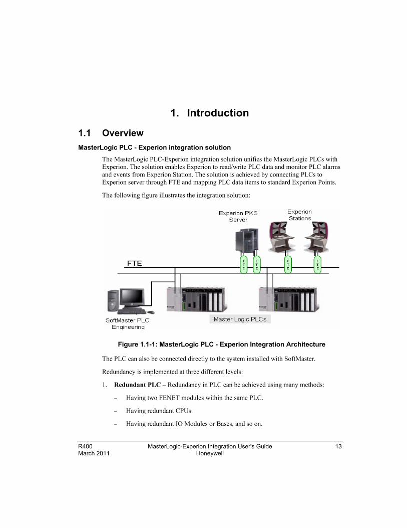
1.1 Overview MasterLogic PLC - Experion integration solution
The MasterLogic PLC-Experion integration solution unifies the MasterLogic PLCs with Experion. The solution enables Experion to read/write PLC data and monitor PLC alarms and events from Experion Station. The solution is achieved by connecting PLCs to Experion server through FTE and mapping PLC data items to standard Experion Points.
The following figure illustrates the integration solution:
Figure 1.1-1: MasterLogic PLC - Experion Integration Architecture
The PLC can also be connected directly to the system installed with SoftMaster.
Redundancy is implemented at three different levels:
1. Redundant PLC – Redundancy in PLC can be achieved using many methods:
− Having two FENET modules within the same PLC.
− Having redundant CPUs.
− Having redundant IO Modules or Bases, and so on.

1. Introduction 1.1. Overview
14 MasterLogic-Experion Integration User's Guide R400 Honeywell March 2011
− The underlying principle is that when the master module fails, the standby module takes over the control without interrupting the operation of the process in control.
2. FTE Network – Two Ethernet cables are connected between the Experion and the PLC or other devices. When the master network connection fails, the standby network connection is used for the communication between the Experion and the PLC.
3. Redundant Experion PKS server – The secondary Experion server takes over when the primary Experion server fails. All the MasterLogic Channels, Controllers, Points and Graphics are also available when the secondary Experion server is active.
ATTENTION
The MasterLogic PLC functions as a non-FTE node together with other FTE nodes on the network.
Integration scope
Experion integration gains special access to intricate areas of MasterLogic PLC through proprietary MLDP:
• Direct variables (%I Input image, %Q Output image, %M internal Memory variables)
• %R File Register variables (non-volatile memory variables – data retention)
• CPU, I/O module, communication Status and Alarms Flags (CPU error, battery error, I/O module)
• Real Time Clock (RTC) areas
• I/O Configuration parameters
• PLC History Logs (Error, Activity, Mode changes, Power shutdown)
• DISOE module integration
1. Introduction 1.1. Overview
R400 MasterLogic-Experion Integration User's Guide 15 March 2011 Honeywell
MasterLogic PLC-Experion integration elements
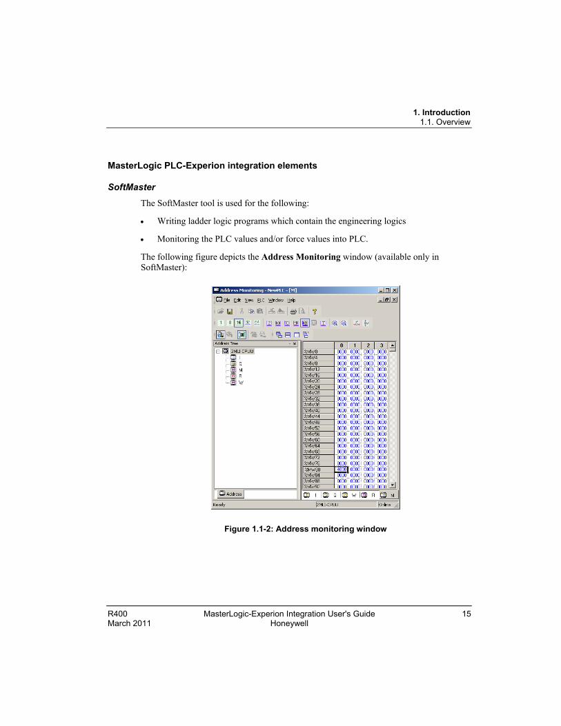
SoftMaster
The SoftMaster tool is used for the following:
• Writing ladder logic programs which contain the engineering logics
• Monitoring the PLC values and/or force values into PLC.
The following figure depicts the Address Monitoring window (available only in SoftMaster):
Figure 1.1-2: Address monitoring window

1. Introduction 1.1. Overview
16 MasterLogic-Experion Integration User's Guide R400 Honeywell March 2011
Quick Builder
Quick Builder is the tool used for the following:
• Configuring MasterLogic Channel, MasterLogic Controller, and Analog and Status Point.
• Uploading/downloading Channel, Controller, and Point from/to the Experion server. The downloaded items are stored in the Experion server database.
Experion Station
Experion station is used for the following:
• Monitoring the online status of PLCs integrated with Experion as Alarms/Events or through Custom graphics.
• Change the online status of MasterLogic Controllers and MasterLogic Channels.
• View the point values obtained from Experion through custom graphics.
Experion has the following two types of stations:
Flex Station – This is generally installed on a computer other than the server computer.
Console Station – Console Station has direct access to the Process Controllers, as well as the Experion server.
MasterLogic PLC
MasterLogic PLC performs the following:
• Replaces the necessary sequential relay circuits for machine control.
• Used in any application that needs some type of electrical control.
• Operates by looking at its inputs and depending on their state, turning on/off its outputs.
• Current MasterLogic PLCs available are ML200 IEC and ML200R.
The high speed Ethernet communication modules (FEnet) of MasterLogic-200 system reside as non FTE nodes on FTE network providing a high-level interface with Experion servers.
MLDP (MasterLogic Dedicated Protocol) server embedded in the FENET modules offer Experion servers, a special proprietary access on TCP-IP layer to various memory variables of the PLC CPU.

1. Introduction 1.1. Overview
R400 MasterLogic-Experion Integration User's Guide 17 March 2011 Honeywell
MasterLogic Server
The PLCs are integrated to Experion server, through the MLServer software. After downloading the Points to Experion server, MLServer performs the following:
• Starts communicating with PLCs.
• Reads PLC information and writes to the Experion server.
• Writes values from the Experion server to PLCs.
• Transfers system status, IO module information, alarms/events associated with PLCs to Experion server which can be monitored via the Experion Station.
Experion Server
The Experion is a standard distributed control system that provides plant-wide control. The Experion server contains supervisory control functions, the Experion Global Data infrastructure and optional redundancy. The server hosts graphical tools such as Control Builder and HMIWeb Display Builder and acts as the central repository for all system data. It also runs all the core system functions, including:
• Data acquisition and processing
• Alarm and event management
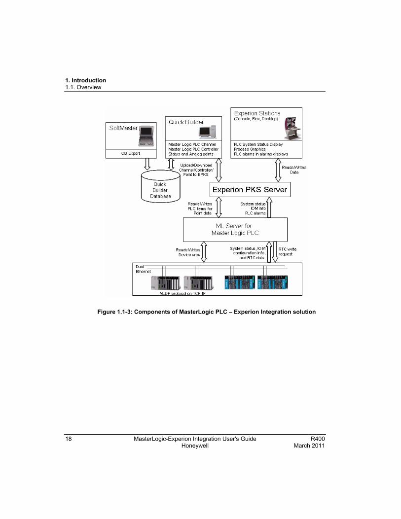
The following picture illustrates the software architecture of the MasterLogic PLC-Experion integration solution.
1. Introduction 1.1. Overview
18 MasterLogic-Experion Integration User's Guide R400 Honeywell March 2011
Figure 1.1-3: Components of MasterLogic PLC – Experion Integration solution

1. Introduction 1.1. Overview
R400 MasterLogic-Experion Integration User's Guide 19 March 2011 Honeywell
Supported MasterLogic PLCs
The supported PLCs are:
• ML200R
• ML200 IEC
ML200R
These are Honeywell’s next generation Programmable Logic Controllers that support CPU-level redundancy. It provides real power, performance and versatility with a compact size, high speed scanning of I/O Channels, and execution of program instructions. It also provides open network through Ethernet, ProfibusTM-DP, DeviceNetTM, remote I/O, and engineer-friendly programming and diagnostic software tools.
ML200
Honeywell’s next generation Programmable Logic Controllers providing real power, performance and versatility with compact size, high speed scanning of I/O Channels and execution of program instructions, open network through Ethernet, ProfibusTM-DP, DeviceNet TM, remote I/O and engineer-friendly programming and diagnostic software tools.

1. Introduction 1.1. Overview
20 MasterLogic-Experion Integration User's Guide R400 Honeywell March 2011

R400 MasterLogic-Experion Integration User's Guide 21 March 2011 Honeywell
2. Installing ML Server
2.1 Installing ML Server in Experion Server This section describes the procedure for installing the MLServer.
• Install Experion server with OPC client license. (The MLServer information provided in this guide is compatible with Experion R400.)
• Install MS-XML version 6.
• Have Administrative privileges to log into the Experion server machine.
REFERENCE - EXTERNAL
For more details on hardware and software requirements, refer to Hardware and Software requirements section in Experion Knowledge Builder.
ATTENTION
You must have Experion OPC client license (Model#: EP-OPCCLI) to configure MasterLogic Channel, Controller, and Point.
MLServer media
The MLServer CD contains the MLServer.exe file required to install the MLServer.
Installing MLServer To install MLServer, perform the following steps:
Step Action
1 Click MLServer.exe in the MLServer installation CD.
ATTENTION
If an earlier version of MLServer is installed already, the wizard displays an error message indicating that the previous MLServer version must be removed before installing the new version.
After performing the initial checks, the wizard displays the welcome screen.
2 Click Next.
The wizard displays the License Agreement screen.

2. Installing ML Server 2.1. Installing ML Server in Experion Server
22 MasterLogic-Experion Integration User's Guide R400 Honeywell March 2011
Step Action
3 Select I accept the terms in the license agreement.
4 Click Next.
The wizard displays the Destination Folder screen.
5 Click Next.
OR
Click Change to select a different folder.
TIP
Honeywell recommends retaining the default destination folder for installing MLServer.
The wizard displays the Ready to Install the Program screen.
6 Click Install.
The wizard displays the Installing Honeywell – MasterLogic Server screen, displaying the status messages and the progress bar during the installation process.
7 The wizard completes the installation and displays the Install Shield Wizard Completed screen:
8 Click Finish to close the wizard.
ATTENTION
MLServer installer displays an error message "Error opening Installation log file. Verify that the specified log file location exists and is writeable". This occurs if Experion is not installed in the machine or if the installer is not run with administrator privileges.
Click OK.
If the Experion server is installed, run MLServer installer with administrator privileges else install Experion server with OPC client license and install MLServer again.

2. Installing ML Server 2.1. Installing ML Server in Experion Server
R400 MasterLogic-Experion Integration User's Guide 23 March 2011 Honeywell
Verifying MLServer installation Verification of MLServer installation involves the following:
Verify graphics pages and xml files copied to the installation path (C:\ProgramData\Honeywell\Experion PKS\Client\Abstract) during installation, as displayed in the following figure.
Figure 2.1-1: Graphics pages and xml files copied during installation

2. Installing ML Server 2.1. Installing ML Server in Experion Server
24 MasterLogic-Experion Integration User's Guide R400 Honeywell March 2011
The following table lists the graphics pages and xml files copied during installation:
Type Filename Description
xml files MLConfig.xml MLMonitor.xml
MLSOEConfig.xml
This file contains the PLC specific configuration.
This file contains common settings for the MLServer and the Graphics.
This file contains SOE configuration for all PLCs.
Graphics pages MLPLC_Config.htm
MLPLC_Status.htm MLPLC_Driver.htm
This Experion graphics page displays the base slot information of the PLCs.
This graphics page displays the PLC status information.
This Experion graphics page displays the MLServer (Driver) diagnostics information.
Schema files MLConfig.xsd
MLMonitor.xsd
MLSOEConfig.xsd
XML schema file for MLConfig.xml
XML schema file for MLMonitor.xml
XML schema file for MLSOEConfig.xml
Verify xml, exe, dll files and document copied to the installation path (typically C:\Program Files\Honeywell\MasterLogicServer) during installation, as shown in the following figure:

2. Installing ML Server 2.1. Installing ML Server in Experion Server
R400 MasterLogic-Experion Integration User's Guide 25 March 2011 Honeywell
Figure 2.1-2: Files copied during installation
The following table lists the xml file, user guide and the template file copied during installation:
Type Filename Description
xml file MLAppSettings.xml
This file is used for configuring the MasterLogic server application settings.
Schema files MLAppSettings.xsd
XML schema file for MLAppSettings.xml.
Document MLServer_Users_Guide.pdf
This user’s guide describes how to integrate the MasterLogic 200R/200 IEC with Experion Process Knowledge System.
Template StatusPointBuildTemplate.txt
This is the template file for Point building.
Configuration Tool
MLServerConfigTool.exe
This utility is used for configuring the PLC information and other information for the

2. Installing ML Server 2.1. Installing ML Server in Experion Server
26 MasterLogic-Experion Integration User's Guide R400 Honeywell March 2011
Type Filename Description MLServer.
Point Build Utility
PointBuildUtility.exe
This utility is used for building the Point corresponding to the PLC and the parameters associated with the Point.
License Application
MLServerLicenseRegistration.exe
This application is used for obtaining a new license, update, terminate and transfer the license.
Demo certificate
MLPLC_Demo.cert
This is a demo certificate file for MLServer for 100 PLC points.
QDB file ML_Sample.qdb This file contains sample ML Channel, ML Controller and sample Analog/Status Points.
The MLServer configuration tool, user’s guide and the license application is accessed through Start > Programs > Honeywell MasterLogic Server. The shortcut for the Configuration tool is available on the desktop.
Figure 2.1-3 Shortcuts to MLServer utilities

2. Installing ML Server 2.2. Installing in Client machines
R400 MasterLogic-Experion Integration User's Guide 27 March 2011 Honeywell
2.2 Installing in Client machines Overview
This section describes the procedure for installing the MLServer in Client machines
Prerequisites for installing MLServer Following are the prerequisites.
• Ensure that you have installed Experion R400 Client (Console/ Flex).
• Ensure that you have logged into the Experion Client machine with Administrative privileges.
MLServer media The MLServer CD contains the MLServer.exe file required to install MLServer.
Installing MLServer To install MLServer, perform the following steps:
Step Action
1 Click MLServer.exe in the MLServer installation CD.
ATTENTION
If an earlier version of MLServer is installed already, the wizard displays an error message indicating that the previous MLServer version must be removed before installing the new version.
After performing the initial checks, the wizard displays the welcome screen.
2 Click Next.
The wizard displays the License Agreement screen.
3 Select I accept the terms in the license agreement.
4 Click Next.
The wizard displays the Destination Folder screen.
5 Click Next.
OR
Click Change to select a different folder.

2. Installing ML Server 2.2. Installing in Client machines
28 MasterLogic-Experion Integration User's Guide R400 Honeywell March 2011
Step Action
TIP
Honeywell recommends retaining the default destination folder for installing MLServer.
The wizard displays the Ready to Install the Program screen.
6 Click Install.
The wizard displays the Installing Honeywell – MasterLogic Server screen, displaying the status messages and the progress bar during the installation process.
7 The wizard completes the installation and displays the Install Shield Wizard Completed screen:
8 Click Finish to close the wizard.
ATTENTION
MLServer installer displays an error message "Error opening Installation log file. Verify that the specified log file location exists and is writeable". This occurs if Experion is not installed in the machine or if the installer is not run with administrator privileges.
Click OK.
If the Experion client is installed, run MLServer installer with administrator privileges else install Experion client and install MLServer again.

2. Installing ML Server 2.2. Installing in Client machines
R400 MasterLogic-Experion Integration User's Guide 29 March 2011 Honeywell
Verifying MLServer installation Verify dll files copied to the installation path (typically C:\Program
Files\Honeywell\MasterLogicServer) during installation, as displayed in the following figure.

2. Installing ML Server 2.3. Getting started
30 MasterLogic-Experion Integration User's Guide R400 Honeywell March 2011
2.3 Getting started Configuring MasterLogic PLC - Experion integration
After installation, the following tasks are performed:
Step Action
1 Installing one or more Ethernet modules (EUTB/FENET) in each PLC. Connecting the Ethernet modules to the Experion server through Ethernet cables.
2 Configuring the IP Addresses of these modules using the SoftMaster tool. Ping the IP Address from the Experion server for verifying the communication between the PLC and the Experion server.
3 Obtaining the license.
4 Configuring MLServer using Configuration Tool.
5 Verifying data exchange between PLC and Experion.

2. Installing ML Server 2.4. Removing MLServer
R400 MasterLogic-Experion Integration User's Guide 31 March 2011 Honeywell
2.4 Removing MLServer
ATTENTION
• After removing the MLServer, the integration between the PLC and the Experion does not work.
• The MLServer must be removed only if the software is upgraded.
• Ensure that the MLServer is stopped before removal.
• Back up the xml files before performing the removal. Using Add/Remove programs
To remove MLServer, perform the following steps:
Step Action
1 Click Start > Settings > Control Panel.
2 Double-click Add/Remove Programs.
The Add/Remove Programs window appears.
3 Select MLServer <Version>and click Remove.
4 Click Yes.
The wizard displays Remove the Program screen.
5 Click OK.
The wizard displays the MLServer <Version> screen, displaying the status messages and the progress bar while the remove operation is in progress.
2. Installing ML Server 2.4. Removing MLServer
32 MasterLogic-Experion Integration User's Guide R400 Honeywell March 2011
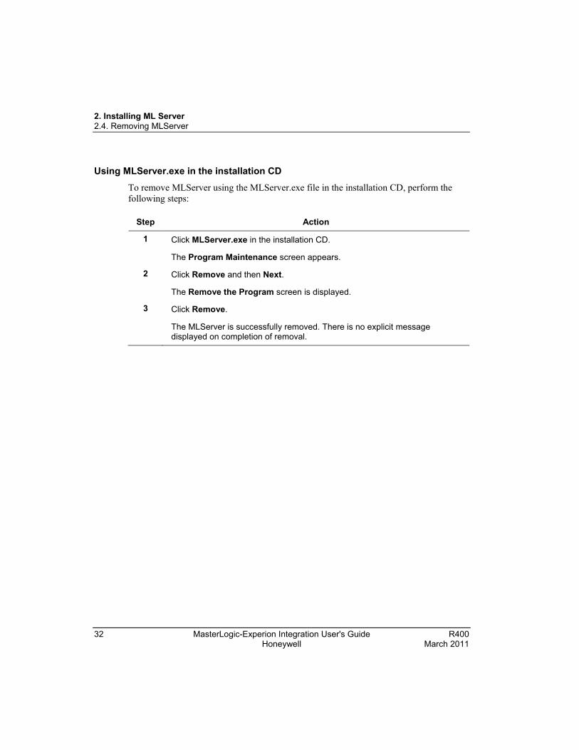
Using MLServer.exe in the installation CD
To remove MLServer using the MLServer.exe file in the installation CD, perform the following steps:
Step Action
1 Click MLServer.exe in the installation CD.
The Program Maintenance screen appears.
2 Click Remove and then Next.
The Remove the Program screen is displayed.
3 Click Remove.
The MLServer is successfully removed. There is no explicit message displayed on completion of removal.

2. Installing ML Server 2.5. Repairing MLServer
R400 MasterLogic-Experion Integration User's Guide 33 March 2011 Honeywell
2.5 Repairing MLServer Using MLServer.exe in the installation CD
The MLServer application can be repaired to fix the installation errors. The missing or corrupt files, shortcuts, and registry entries can be fixed using this option.
To fix the installation errors, perform the following steps:
Step Action
1 Click MLServer.exe file in the installation CD.
The Program Maintenance screen appears.
2 Select Repair and click Next.
3 Click Repair.
The installation errors are successfully repaired. There is no explicit message displayed on completion of repair.

2. Installing ML Server 2.5. Repairing MLServer
34 MasterLogic-Experion Integration User's Guide R400 Honeywell March 2011

R400 MasterLogic-Experion Integration - User's Guide 35 March 2011 Honeywell
3. MLServer License
3.1 Overview Background
After installing the MLServer, you must register and obtain the license prior to using it.
Before you begin Before obtaining the license, ensure that you have the following items:
• Voucher ID – This is provided by Honeywell when you purchase the MLServer.
• Host ID Files – These files are automatically created when you open the MLServer License Registration Application or enable the ML Channel for the first time. Names of the Host ID files are <Computer Name>.Zip and <Computer Name>.HID, example: If the computer name is EPKSSRVRPC1 then the Host ID files created are EPKSSRVRPC1.zip and EPKSSRVRPC1.HID. These files are available in the installation path (typically C:\Program files\Honeywell\MasterLogicServer).
Obtaining the license
Request by email – Send an e-mail to [email protected] attaching the Host ID files that is <Computer Name>.Zip and <Computer Name>.HID and mentioning the voucher ID to obtain the license.
ATTENTION
• Separate e-mail needs to be sent for getting license for each Experion server attaching the Host ID files of the corresponding computer.
• For a redundant Experion server two licenses must be obtained, one for each server machine.
Using the demo versions of MLServer
The license certificate for the demo version of MLServer is automatically created and activated when the MLServer is installed. The demo version of MLServer allows configuring 100 Points and there is no restriction on the number of PLCs. There is no validity period for the demo license.

3. MLServer License 3.1. Overview
36 MasterLogic-Experion Integration User's Guide R400 Honeywell March 2011
ATTENTION
After obtaining the original license, the demo license of MLServer is replaced with the original license.
MLServer license features
The following two features are licensed for MLServer:
• Number of PLCs
• Number of PLC points that can be used across all the PLCs
For example, if the obtained license supports 10 PLCs and 1000 PLC points,
• The MLServer communicates with a maximum of 10 PLCs.
• A maximum of 1000 PLC points can be used for data communication across all the PLCs.
Experion point and PLC point Experion Analog/Status points are configured using the Quick Builder in the MasterLogic Controllers for data communication with the PLC. The PLC points defined within these Experion points provide a way of addressing the location in PLC where the values are stored.
3. MLServer License 3.2. Obtaining a new license
R400 MasterLogic-Experion Integration - User's Guide 37 March 2011 Honeywell
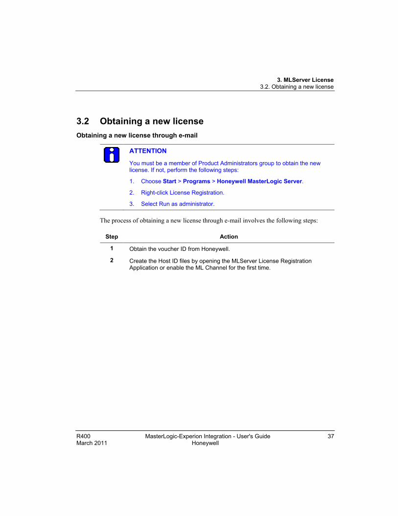
3.2 Obtaining a new license Obtaining a new license through e-mail
ATTENTION
You must be a member of Product Administrators group to obtain the new license. If not, perform the following steps:
1. Choose Start > Programs > Honeywell MasterLogic Server.
2. Right-click License Registration.
3. Select Run as administrator.
The process of obtaining a new license through e-mail involves the following steps:
Step Action
1 Obtain the voucher ID from Honeywell.
2 Create the Host ID files by opening the MLServer License Registration Application or enable the ML Channel for the first time.

3. MLServer License 3.2. Obtaining a new license
38 MasterLogic-Experion Integration User's Guide R400 Honeywell March 2011
Step Action
3 Send an e-mail to [email protected] with the following details:
• In the Subject line, type the voucher ID as – VOUCHID :< voucher ID>. For example, type – VOUCHID: MLPLC_1PLC_50POINTS.
• Attach the Host ID files that is <Computer Name>.zip and <Computer Name>.HID files.
ATTENTION
• The Subject line is case-sensitive.
• Other than the Subject line, do not type any information in the e-mail.
• After receiving the e-mail, Honeywell sends the new license certificate in a zip file. This file must be unzipped using the password, password.
4 Save the license certificate in the MLServer system. This license certificate can be re-installed if the Experion server machine is reformatted.

3. MLServer License 3.2. Obtaining a new license
R400 MasterLogic-Experion Integration - User's Guide 39 March 2011 Honeywell
Installing license certificate To install the new license certificate received from Honeywell, perform the following steps:
Step Action
1 Click Start > Programs > Honeywell MasterLogic Server > License Registration.
The MLServer License Registration dialog box appears.
2 Click Browse to select the license certificate received from Honeywell.

3. MLServer License 3.2. Obtaining a new license
40 MasterLogic-Experion Integration User's Guide R400 Honeywell March 2011
Step Action
• The selected license certificate appears in Certificate file path as shown in the following figure:
3 Click OK.
The MLServer License dialog box appears displaying the licensed number of PLCs and PLC points.
ATTENTION
The license need not be terminated before uninstalling MLServer software. The license is retained and active when the MLServer software is re-installed in the same machine.

3. MLServer License 3.3. Updating license certificate
R400 MasterLogic-Experion Integration - User's Guide 41 March 2011 Honeywell
3.3 Updating license certificate Updating license certificate
The updated license certificate can be received from Honeywell with additional features (like more number of points). After installing the license certificate on an Experion server, the features including the number of points are updated.
To update the license certificate, perform the following steps:
Step Action
1 Obtain the new voucher ID (supersede of the original voucher) from Honeywell.
2 Send an e-mail to [email protected] with the following detail:
• In the Subject line, type the voucher ID as – VOUCHID :< voucher ID>. For example, type – VOUCHID: MLPLC_1PLC_50POINTS _Supersede.
• Attach the Host ID files that is <Computer Name>.zip and <Computer Name>.HID files.
ATTENTION
• The Subject line is case-sensitive.
• Other than the Subject line, do not type any information in the e-mail.
• After receiving the e-mail, Honeywell sends the new superseded license certificate in a zip file. This file must be unzipped using the password, password.
3 Save the license certificate in the MLServer system. This license certificate can be re-installed if the Experion server machine is reformatted.
4 Choose Start > Programs > Honeywell MasterLogic Server > License Registration.

3. MLServer License 3.3. Updating license certificate
42 MasterLogic-Experion Integration User's Guide R400 Honeywell March 2011
Step Action
• The MLServer License dialog box appears.
5 Click Supersede License.
The Enter Password dialog box appears.
6 Type the password as mlplcr400 and click OK.
ATTENTION
If the MLServer version is R4xx, use mlplcr400 as password.
7 Click Yes to continue.

3. MLServer License 3.3. Updating license certificate
R400 MasterLogic-Experion Integration - User's Guide 43 March 2011 Honeywell
Step Action
• The Re-license MLServer dialog box appears.
8 Click Browse to select the new license certificate.
9 Select the file and click Open.
• The selected certificate appears in New certificate file path as shown in the following figure:

3. MLServer License 3.3. Updating license certificate
44 MasterLogic-Experion Integration User's Guide R400 Honeywell March 2011
Step Action
10 Click OK.
• The following message box appears.
11 Click OK.
The MLServer License Registration dialog box appears displaying the superseded license features.
12 Restart MLServer for the new license to take effect.

3. MLServer License 3.4. Transferring license certificate
R400 MasterLogic-Experion Integration - User's Guide 45 March 2011 Honeywell
3.4 Transferring license certificate The process of transferring the license certificate from one Experion server to another involves the following tasks:
• Terminate the license certificate on the first Experion server.
• Install the license certificate on the new Experion server.
CAUTION
If the license is terminated, it cannot be re-installed in the same machine. To re-install the license the machine must be formatted.

3. MLServer License 3.4. Transferring license certificate
46 MasterLogic-Experion Integration User's Guide R400 Honeywell March 2011
Terminating license certificate
To terminate the license certificate, perform the following steps on the first Experion server:
Step Action
1 Click Start > Programs > Honeywell MasterLogic Server > License Registration.
• The MLServer License dialog box appears.
2 Click Terminate License.
The Enter Password dialog box appears.
3 Type the password as mlplcr400 and click OK.
ATTENTION
If the MLServer version is R4xx, use mlplcr400 as password.

3. MLServer License 3.4. Transferring license certificate
R400 MasterLogic-Experion Integration - User's Guide 47 March 2011 Honeywell
Step Action
• The following message box appears.
4 Click Yes to continue.
• The license is terminated and the following message appears.
ATTENTION
The *.term file generated after terminating the license can be used for transferring the license to a different machine.
Transferring license certificate
To transfer the license certificate to a different Experion server, perform the following steps:
Step Action
1 Create the Host ID files by opening the MLServer License Registration Application or enable the ML Channel for the first time.
2 Send an e-mail to [email protected] with the following details:
• In the Subject line, type the voucher ID as – VOUCHID :< voucher ID>. For example, type – VOUCHID: MLPLC_1PLC_50POINTS.
• Select the <Computer Name>.HID and the termination certificate (*.term) files and create a zip file with the password, password. Attach this zip file to the e-mail.
Note: Ensure not to select the option to save the folder information while
3. MLServer License 3.4. Transferring license certificate
48 MasterLogic-Experion Integration User's Guide R400 Honeywell March 2011
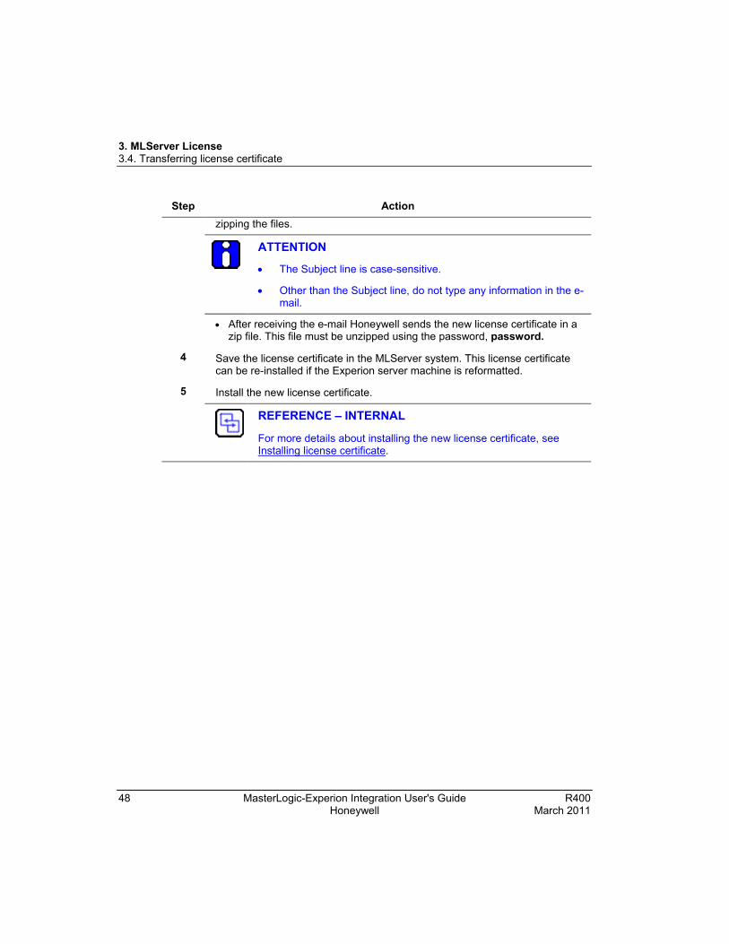
Step Action zipping the files.
ATTENTION
• The Subject line is case-sensitive.
• Other than the Subject line, do not type any information in the e-mail.
• After receiving the e-mail Honeywell sends the new license certificate in a zip file. This file must be unzipped using the password, password.
4 Save the license certificate in the MLServer system. This license certificate can be re-installed if the Experion server machine is reformatted.
5 Install the new license certificate.
REFERENCE – INTERNAL
For more details about installing the new license certificate, see Installing license certificate.

R400 MasterLogic-Experion Integration - User's Guide 49 March 2011 Honeywell
4. Configuration
4.1 Overview Configuring MasterLogic server
To communicate with the PLCs, the MLServer must be configured with PLC information. This configuration involves the following tasks:
• Configuring MLServer using Configuration Tool
• Configuring MLServer using Quick Builder
• Downloading Quick Builder Points to Experion
The following diagram depicts the configuration of MLServer:
Figure 4.1-1: MasterLogic Server configuration

4. Configuration 4.2. Configuring MLServer using Configuration Tool
50 MasterLogic-Experion Integration User's Guide R400 Honeywell March 2011
4.2 Configuring MLServer using Configuration Tool MLServer Configuration Tool
The PLC information must be configured for the MLServer using the MLServer Configuration Tool. The PLC information like PLC Name, Id, Type, IP Address, and Logs are configured for each PLC in the plant. The tool consists of the following tabs:
• PLC
• LOGS
• ADVANCED
ATTENTION
The PLC information configured using the configuration tool must be saved.
The MLServer must be restarted for the changes to take effect. However, the exception is that when the MLServer or Protocol Log file settings are changed, there is no need to restart the MLServer.
To configure the PLC information, perform the following steps:
Step Action
1 Choose Start > Programs > Honeywell MasterLogic Server > Configuration Tool.
The following window appears.
4. Configuration 4.2. Configuring MLServer using Configuration Tool
R400 MasterLogic-Experion Integration - User's Guide 51 March 2011 Honeywell
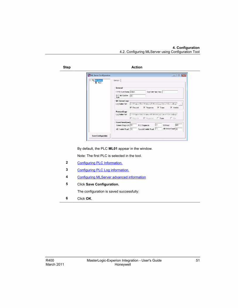
Step Action
By default, the PLC ML01 appear in the window.
Note: The first PLC is selected in the tool.
2 Configuring PLC Information.
3 Configuring PLC Log information.
4 Configuring MLServer advanced information
5 Click Save Configuration.
The configuration is saved successfully:
6 Click OK.

4. Configuration 4.2. Configuring MLServer using Configuration Tool
52 MasterLogic-Experion Integration User's Guide R400 Honeywell March 2011
Step Action
7 Repeat steps 1 through 7 for each PLC in the plant.
Note: The PLCs must be added using the procedure Adding a new PLC.
Tip
The ToolTip appears when the cursor is placed over the options available in the MLServer Configuration tool. The ToolTip provides additional information about the setting options.
Configuring PLC Information
The PLC tab in the configuration tool is used for the following purposes:
• Configuring the general PLC information used by MLServer to communicate with the PLC.
• Enabling/Disabling the IO Read and other features within the MLServer.
To configure the PLC information, perform the following steps:
Step Action
1 Select the PLC ID from the left pane.
The PLC information appears in the PLC tab as shown in the following figure.

4. Configuration 4.2. Configuring MLServer using Configuration Tool
R400 MasterLogic-Experion Integration - User's Guide 53 March 2011 Honeywell
Step Action
3 Enter PLC Name.
Note: The PLC Name is a unique name for each PLC. It is alphanumeric and there is no limit on the number of characters. Example – MLPLC1. Separate logs are created for each PLC based on the PLC ID.
4 Select the PLC type from the PLC Type list box
Note: The supported PLCs are ML200-IEC and ML200R.
5 Enter the EPKS Asset Name for this PLC. All the Alarms/Events raised by the MLServer are in this asset.
REFERENCE – EXTERNAL
For more details on configuring and creating asset, refer Experion Knowledge Builder > Experion R400 > Configuration > Enterprise Model Builder User’s Guide > Accessing Enterprise Model Builder > Creating and Configuring Assets.
6 Enter IPAddress1, IPAddress2, IPAddress3 and IPAddress4.
Note:
IPAddress1- Represents the primary PLC’s IP address in Primary Network.
IPAddress2- Represents the secondary or redundant PLC’s IP address in Primary Network.
IPAddress3- Represents the primary PLC’s IP address in Secondary Network, in case of dual network.
IPAddress4- Represents the secondary or redundant PLC’s IP address in Secondary Network, in case of dual network.
The MLServer searches for a valid PLC connection in the following sequence: IP Address1, 2, 3 and 4.
7 To view PLC status information in the Experion graphics display select Status Read and EPKS Write check boxes in Monitor.
8 To view IO module information in the Experion graphics display select IO Read and EPKS Write check boxes in Monitor.
9 Auto Point Build check box is used for building the ML points. It must be enabled to use the PLC.
If any PLC is configured and not used, then disable the check box.

4. Configuration 4.2. Configuring MLServer using Configuration Tool
54 MasterLogic-Experion Integration User's Guide R400 Honeywell March 2011
Step Action
10 To view PLC status Alarms / Messages in the Experion Alarm summary display select Status Read and Alarm Raising check boxes in Monitor.
11 To view the updated RTC time in Experion graphics display select Enable Read/Write in RTC and EPKS Write under Monitor.
Enable Read/Write If Yes, it allows MLServer to read/write RTC time from/to PLC.
Synch Interval Indicates the time frequency for reading the RTC time from the PLC and updating in Experion.
Note: If this value is 0 then the RTC time is not read or written from/to the PLC.
Deadband The value set for Deadband under RTC indicates the difference in time between the PLC and System Time beyond which the RTC time is written to the PLC.
The PLC time is updated with the Experion system time, if the time difference is equal to or greater than RTC Deadband.
Note: If this value is 0 then the RTC time is not written to the PLC.
12 To view PLC related alarms like MLServer Licensing Alarms, PLC connection and disconnection in the Alarm summary display, select Alarm Raising check box under Monitor.

4. Configuration 4.2. Configuring MLServer using Configuration Tool
R400 MasterLogic-Experion Integration - User's Guide 55 March 2011 Honeywell
Configuring PLC Log information The LOGS tab in the configuration tool is used for the following purposes:
• Configuring settings for transfer of the PLC Logs into the MLServer
• Enabling/Disabling the PLC level MLServer and Protocol logs
To configure the PLC log information, perform the following steps:
Step Action
1 Select the PLC ID from the left pane and click LOGS tab.
2 Select the Initial History check box if the already existing events in the PLC Log need to be transferred to Experion server or Log files during startup of the MLServer.
Note: Honeywell recommends that this option need not be selected.
3 Select the Log To File check box if the events in the PLC Log need to be transferred to corresponding MLServer log files.
Note: Honeywell recommends that this option need not be selected.

4. Configuration 4.2. Configuring MLServer using Configuration Tool
56 MasterLogic-Experion Integration User's Guide R400 Honeywell March 2011
Step Action
4 Select the Events check box if the events in PLC Log need to be transferred to Experion server as Events/Alarms.
Note: Honeywell recommends that this option can be selected for the desired PLC log.
5 The Event Category selection indicates whether the event needs to be transferred to Experion as Alarms or Events. The possible values are System Alarm and System Event.
Note: Honeywell highly recommends that the default System event setting must not be changed.
6 Click under MLServer Logs to browse and select the folder path to save the MLServer log files.
7 Click under Protocol Logs to browse and select the folder path to save the Protocol log files.
8 Select Request, Response, Trace and Monitor under MLServer Logs to enable the generation of corresponding logs.
9 Select Request, Response, Trace and Hex under MLServer Logs to enable the generation of corresponding logs.
ATTENTION
Honeywell recommends not enabling Hex log as the Hex logs need more disk space and reduce the overall system performance.

4. Configuration 4.2. Configuring MLServer using Configuration Tool
R400 MasterLogic-Experion Integration - User's Guide 57 March 2011 Honeywell
Configuring MLServer advanced information
The ADVANCED tab in the configuration tool is used for configuring MLServer advanced settings.
To configure the MLServer advanced information, perform the following steps:
Step Action
1 Select the PLC ID from the left pane and click ADVANCED tab.
The MLServer advanced information appears as shown in the following figure:
ATTENTION
Honeywell recommends that these settings and the default values (except for configured bases) need not be changed. If you need to change this configuration, contact the Honeywell technical support team.

4. Configuration 4.2. Configuring MLServer using Configuration Tool
58 MasterLogic-Experion Integration User's Guide R400 Honeywell March 2011
Configure Bases is an option provided to configure the existing Bases to improve the performance of MLServer. This is an optional setting, For ML200R, bases 1 to 31 are available and for ML200IEC bases 1 to 7 are available.
Figure 4.2-1: Advanced tab for ML200IEC
Figure 4.2-2: Advanced tab for ML200R

4. Configuration 4.2. Configuring MLServer using Configuration Tool
R400 MasterLogic-Experion Integration - User's Guide 59 March 2011 Honeywell
For example, to configure bases 2 and 30, perform the following steps.
Step Action
1 Select Base2 from the left list.
2 Click >> button.
3 B2 will be visible in the list on right side.
4 Click Save Configuration.
Note: If the configured bases are given, only the configured bases will be visible in Station. If not configured, few non-existing bases will also be visible in the Station.
Adding a new PLC The PLCs in the plant must be added and configured in the MLServer Configuration tool for the MLServer to communicate with the PLCs.
To add a new PLC, perform the following steps:
Step Action
1 Click Start > Programs > Honeywell MasterLogic Server > Configuration Tool.
2 Right click MLServer and select Add PLC.

4. Configuration 4.2. Configuring MLServer using Configuration Tool
60 MasterLogic-Experion Integration User's Guide R400 Honeywell March 2011
Step Action
A new PLC is added as shown in the following figure.

4. Configuration 4.2. Configuring MLServer using Configuration Tool
R400 MasterLogic-Experion Integration - User's Guide 61 March 2011 Honeywell
Step Action

4. Configuration 4.2. Configuring MLServer using Configuration Tool
62 MasterLogic-Experion Integration User's Guide R400 Honeywell March 2011
Deleting a PLC To delete a PLC, perform the following steps:
Step Action
1 Click Start > Programs > Honeywell MasterLogic Server > Configuration Tool.
2 Right-click the PLC ID from the left pane and select Delete PLC.
The following confirmation message appears.
If you select Yes, the PLC configuration information is deleted.

4. Configuration 4.2. Configuring MLServer using Configuration Tool
R400 MasterLogic-Experion Integration - User's Guide 63 March 2011 Honeywell
Configuring MLServer general information To configure the MLServer general information, perform the following steps:
Step Action
1 Click Start > Programs > Honeywell MasterLogic Server > Configuration Tool.
2 Select MLServer from the left pane.
• The following window appears:
3 Enter the EPKS Asset Name for the general MLServer Alarms. All Alarms raised by the MLServer is in this asset.
4 Enter the Log Retention Days for the MLServer and Protocol Logs. The MLServer automatically deletes the log files that are older than these days.
5 Enter the PLC Info Update Rate which indicates how fast the changes in the dynamic MLConfig XML parameters (Log files enabling / disabling, and so on) are detected.

4. Configuration 4.2. Configuring MLServer using Configuration Tool
64 MasterLogic-Experion Integration User's Guide R400 Honeywell March 2011
Step Action
6 Click under MLServer Logs to browse and select the folder path to save the MLServer log files.
7 Select Request, Response, Trace and Monitor under MLServer Logs to generate the corresponding general logs.
8 Click under Protocol Logs to browse and select the folder path to save the Protocol Stack log files.
9 Select Request, Response, Trace and Hex under Protocol Logs to generate the corresponding general logs.
10 Enter the scan period for General Diagnostic, PLC Diagnostic, IO Read, AD Module Read, Special Module Read and All Module Read under Scan Period.
General Diagnostics – Frequency at which the general diagnostics parameters in the Driver Info Experion display are collected.
PLC Diagnostics – Frequency at which the PLC specific diagnostics parameters in the Driver Info Experion display are collected.
IO Read – Frequency at which the IO Module information is read from all the PLCs.
AD Module Read – Frequency at which the AD Module information is read from the PLCs.
Special Module Read – Frequency at which the Special Module parameters are read from the U memory area of the PLCs. The Bad PV is set for the corresponding Experion parameters based on this parameter.
All Module Read – Frequency at which the module level errors, Max/Min/Current Scan periods are read from the F Area for the ML200 PLCs.
11 Click Save Configuration.
ATTENTION
The configuration must be performed with MLConfig utility only in primary server.
For all the configuration changes to be reflected in backup server, the replication of abstract folder and the Database synchronization must be performed between the primary and backup servers.

4. Configuration 4.3. Configuring MLServer using Quick Builder
R400 MasterLogic-Experion Integration - User's Guide 65 March 2011 Honeywell
4.3 Configuring MLServer using Quick Builder Overview of Quick Builder components The MLServer must be configured using the Quick Builder. The configuration involves the following tasks:
• Configuring the Quick Builder component manager
• Configuring a MasterLogic Channel
• Configuring a MasterLogic Controller
• Configuring an Experion Point (Analog and Status)
REFERENCE - EXTERNAL
For more details on Experion Quick Builder tool, see Experion PKS Knowledge Builder > Experion PKS R400 > Configuration > Quick Builder Guide.
TIP
For example on configuring ML Channel, Controller and Points, refer to the sample QDB file (ML_Sample.qdb) in the installation folder.
Configuring the Quick Builder component manager
To enable configuring the MasterLogic Channel, MasterLogic Controller and Analog and Status Points in Quick Builder, the Quick Builder component manager must be configured.
ATTENTION
You must have Experion OPC client license (Model number: EP-OPCCLI) to configure the MasterLogic Channel, Controller and Point.

4. Configuration 4.3. Configuring MLServer using Quick Builder
66 MasterLogic-Experion Integration User's Guide R400 Honeywell March 2011
To configure the Quick Builder component manager, perform the following steps:
Step Action
1 Create a new project in Quick Builder.
• The Enable Components dialog box is displayed.
2 Select Experion server from Server drop-down list.
3 Click Enable Components tab.
4 Select MasterLogic from Other components.
5 Select Analog Point and Status Point from Point components.
4. Configuration 4.3. Configuring MLServer using Quick Builder
R400 MasterLogic-Experion Integration - User's Guide 67 March 2011 Honeywell
Step Action
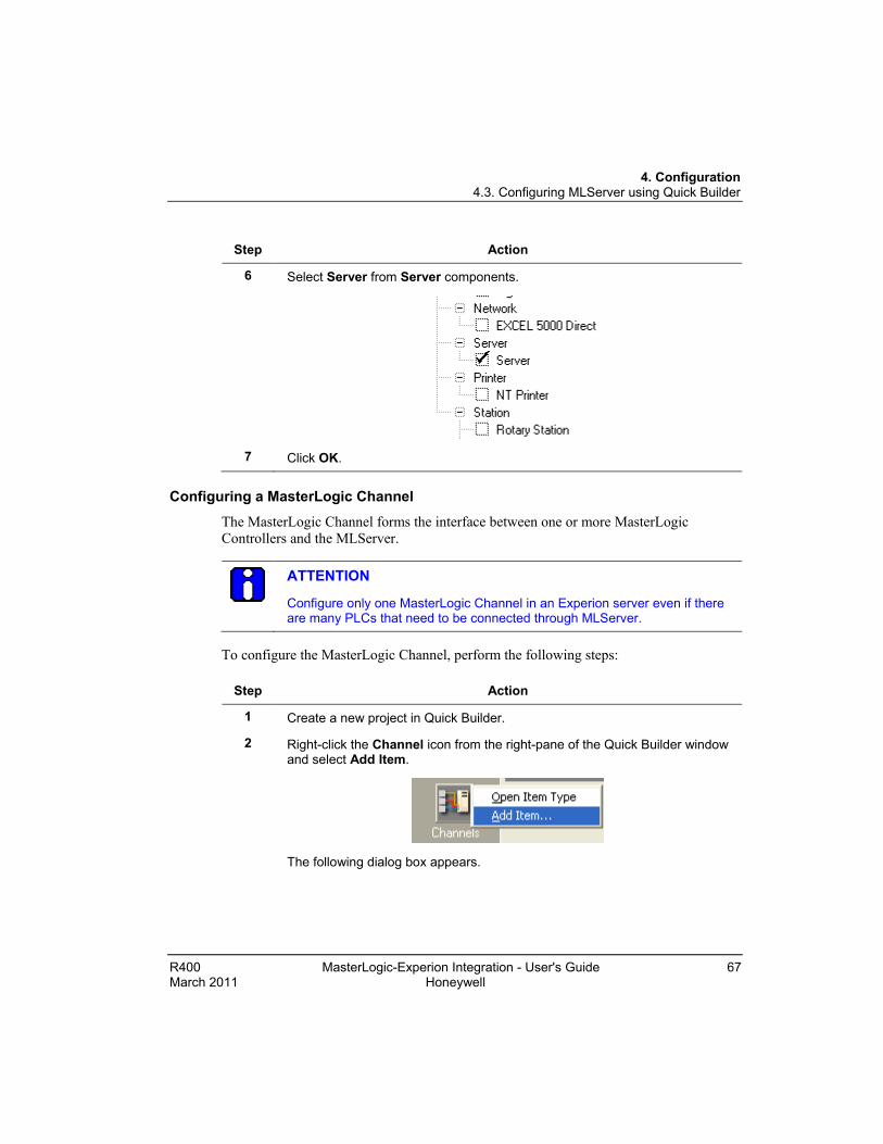
6 Select Server from Server components.
7 Click OK. Configuring a MasterLogic Channel
The MasterLogic Channel forms the interface between one or more MasterLogic Controllers and the MLServer.
ATTENTION
Configure only one MasterLogic Channel in an Experion server even if there are many PLCs that need to be connected through MLServer.
To configure the MasterLogic Channel, perform the following steps:
Step Action
1 Create a new project in Quick Builder.
2 Right-click the Channel icon from the right-pane of the Quick Builder window and select Add Item.
The following dialog box appears.

4. Configuration 4.3. Configuring MLServer using Quick Builder
68 MasterLogic-Experion Integration User's Guide R400 Honeywell March 2011
Step Action
3 Select Channel and MasterLogic Channel type in the Add Item(s) dialog box.
4 Select Channels icon from the left-pane of the Quick Builder window. From the right pane, select the channel that you want to configure.
5 Configure the Main tab of the Channel as follows:

4. Configuration 4.3. Configuring MLServer using Quick Builder
R400 MasterLogic-Experion Integration - User's Guide 69 March 2011 Honeywell
Step Action
6 Ensure that the Host Name contains localhost.
7 Select the Background Scan period.
Note: This parameter is used in conjunction with the Controller’s Background Scan parameter. Honeywell recommends you to retain the default value (60).
ATTENTION
Ensure that the Item Number for the channel configured is unique.
If the number of OPC channels configured in the Experion server is more than 5 or the number of OPC controllers configured is more than 20, then increase the channel "Connect Timeout" parameter to 15 seconds and "Read Timeout" parameter to 3 seconds. If the load is more than this limit, increase the connect timeout to 20 seconds.

4. Configuration 4.3. Configuring MLServer using Quick Builder
70 MasterLogic-Experion Integration User's Guide R400 Honeywell March 2011
Step Action
WARNING
• The Background Scan Period,
− Must be greater than PV/OP/SP Scan Period. (The PV/OP/SP Scan Period is set during Point configuration).
− Must not be equal to 0.
• If the Background Scan Period is lesser than PV/OP/SP Scan Period, the MLServer does not function properly.
REFERENCE – EXTERNAL
For more details on adding and configuring a Channel, see Experion Knowledge Builder > Experion PKS R400 > Configuration > Quick Builder Guide > Configuring Controllers and Channels.
Configuring a MasterLogic Controller
The MasterLogic Controller is Quick Builder's mechanism for configuring one or more groups with the same deadband. It is a logic grouping and does not represent a physical device (that is the PLC controller).
To configure the MasterLogic Controller, perform the following steps:
Step Action
1 Create a new project in Quick Builder.
2 Add a MasterLogic Channel to the project.
REFERENCE – INTERNAL
For more details on adding a MasterLogic Channel, see Configuring a MasterLogic Channel.
3 Right-click the Controller icon from the right-pane of the Quick Builder window and select Add Item.
The Add Item(s) dialog box appears:
4 Select Controller and MasterLogic Controller in the Add Item(s) dialog box.
5 Select the Controllers icon from the left-pane of the Quick Builder window. From the right pane, select the controller that you want to configure.
4. Configuration 4.3. Configuring MLServer using Quick Builder
R400 MasterLogic-Experion Integration - User's Guide 71 March 2011 Honeywell
Step Action
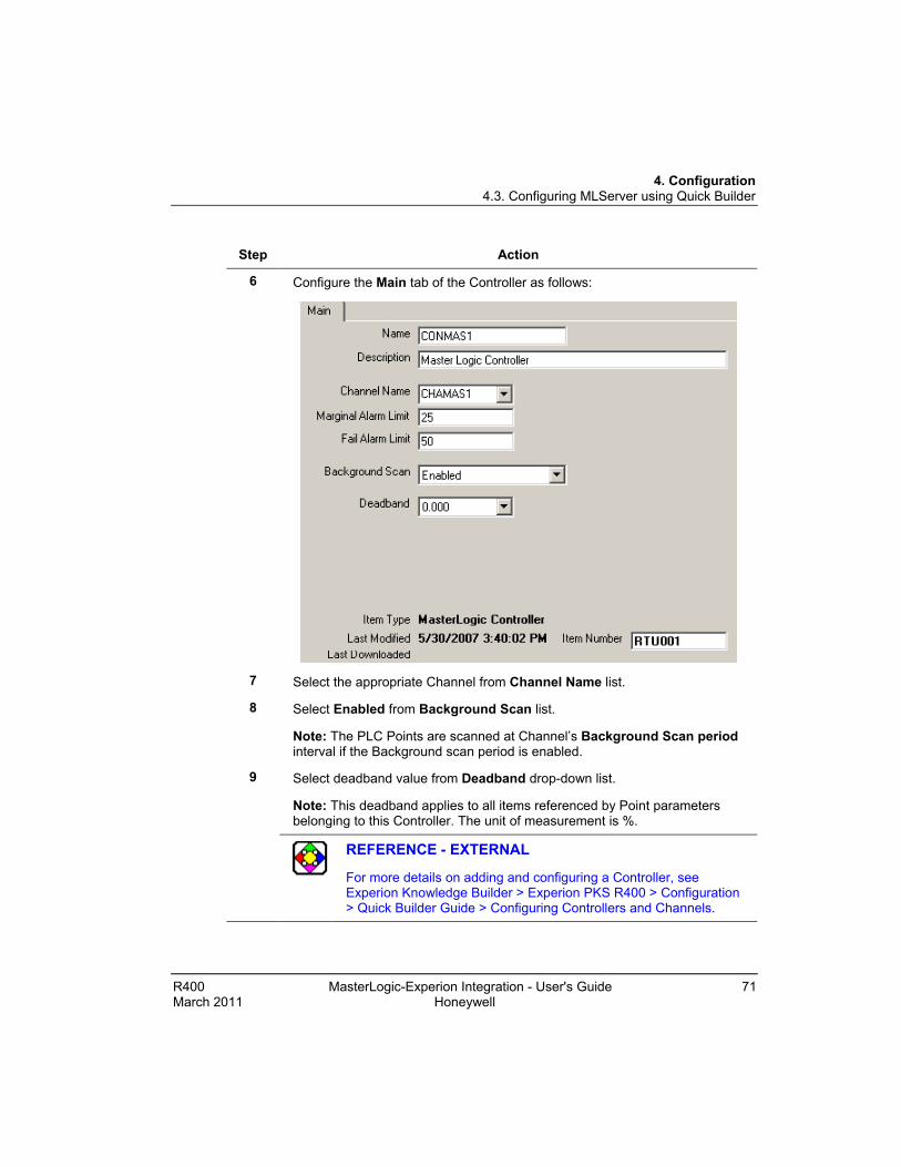
6 Configure the Main tab of the Controller as follows:
7 Select the appropriate Channel from Channel Name list.
8 Select Enabled from Background Scan list.
Note: The PLC Points are scanned at Channel’s Background Scan period interval if the Background scan period is enabled.
9 Select deadband value from Deadband drop-down list.
Note: This deadband applies to all items referenced by Point parameters belonging to this Controller. The unit of measurement is %.
REFERENCE - EXTERNAL
For more details on adding and configuring a Controller, see Experion Knowledge Builder > Experion PKS R400 > Configuration > Quick Builder Guide > Configuring Controllers and Channels.

4. Configuration 4.3. Configuring MLServer using Quick Builder
72 MasterLogic-Experion Integration User's Guide R400 Honeywell March 2011
Configuring an Experion Point (Analog and Status) Analog and Status Points are used for exchanging the MasterLogic data with Experion. The Quick Builder Point parameter represents a mapping to an item on the MLServer.
ATTENTION
The PV, SP and OP values are configured as parameters for a point. They do not refer to the general Process Control Industry meaning.
Configuring an Experion Analog Point To configure the Experion Analog Point, perform the following steps:
Step Action
1 Create a new project in Quick Builder.
2 Add a MasterLogic Channel and one (or more) MasterLogic Controller (s) corresponding to each PLC configured in the Plant.
REFERENCE – INTERNAL
For more details on adding MasterLogic Channel and Controller, see Configuring a MasterLogic Channel and Configuring a MasterLogic Controller.
3 Right-click the Point icon from the right-pane of the Quick Builder window and select Add Item.
The Add Item(s) dialog box appears:
4 Select Point and Analog Point type in the Add Item(s) dialog box.
5 Select the Points icon from the left-pane of the Quick Builder window. From the right pane, select the point that you want to configure.
6 Configure the Main tab as follows:

4. Configuration 4.3. Configuring MLServer using Quick Builder
R400 MasterLogic-Experion Integration - User's Guide 73 March 2011 Honeywell
Step Action
7 Enter the Parent Asset for the point. All Alarms/Events raised by Experion (value change Events, Range checking Alarms, and so on.) is in this Asset.
TIP
Honeywell recommends that the Parent Asset configured for the points here must be the same as the EPKS Asset Name configured in the MLServer Configuration Tool for the PLC referred in this point.
8 Select ellipse button next to PV Source Address.
The Address Builder dialog box is displayed.
9 Select Controller from Address Type drop-down list and appropriate Controller name from Controller drop-down list. Enter PLC Point name in Location.
Note: The PLC Point name includes the PLC ID, memory area, command, and data type. The name of the user-defined data format is also provided in the PLC Point name.

4. Configuration 4.3. Configuring MLServer using Quick Builder
74 MasterLogic-Experion Integration User's Guide R400 Honeywell March 2011
Step Action
REFERENCE – INTERNAL
• For more details on PLC Point name, refer to PLC Point configuration details.
• For more details on user-defined data format, see Defining data formats.
WARNING
If the user defined data format is not defined in Experion, then the entire item is not recognized by the MLServer.
10 Configure the Control tab as follows:

4. Configuration 4.3. Configuring MLServer using Quick Builder
R400 MasterLogic-Experion Integration - User's Guide 75 March 2011 Honeywell
Step Action
11 Enter setpoint’s Source Address and Dest Address through Address Builder dialog box. (Optional)
Note:
• Setpoint Source Address: This denotes the address from where SP reads the associated parameter value that can be viewed in the Experion Station.
• Setpoint Dest Address: The value written to SP is transferred to this location in the PLC.
TIP
Honeywell recommends you to configure the same PLC memory address for both the source and destination addresses of the SP parameter.
12 Select the Scan Period for SP.
Note: This represents the interval at which the SP parameter’s value is updated from the PLC Address specified in SP Source Address.
WARNING
The Scan Period,
− Must be less than the Background Scan Period configured for the MasterLogic Channel.
− Must not be equal to 0.
13 Enter Output’s Source Address and Dest Address through Address Builder dialog box. (Optional)
Note:
• Output Source Address: This denotes the address from where OP reads the associated parameter value that can be viewed in the Experion Station.
• Output Dest Address: The value written to OP is transferred to this location in the PLC.
TIP
Honeywell recommends you to configure the same PLC memory address for both the source and destination addresses of the OP parameter.

4. Configuration 4.3. Configuring MLServer using Quick Builder
76 MasterLogic-Experion Integration User's Guide R400 Honeywell March 2011
Step Action
14 Select the Scan Period for OP.
Note: This represents the interval at which the OP parameter’s value is updated from the PLC Address specified in OP Source Address.
WARNING
The Scan Period,
− Must be less than the Background Scan Period configured for the MasterLogic Channel.
− Must not be equal to 0.
TIP
The values for SetPoint and Output need not be defined for every Experion point.
REFERENCE – EXTERNAL
For more details on adding and configuring Points, see Experion Knowledge Builder > Experion PKS R400 > Configuration > Quick Builder Guide > Point Properties.
Configuring an Experion Status Point
REFERENCE - INTERNAL
Configuring the Main tab of Status Point is similar to configuring the Main tab of an Analog Point. Instead of selecting an Analog Point, select a Status Point. For details about configuring an Analog Point, see Configuring an Experion Analog Point.
To configure an Experion Status Point, perform the following:
Step Action
1 Create a new project in Quick Builder.
2 Add a MasterLogic Channel and one (or more) MasterLogic Controller corresponding to each PLC configured in the Plant.
4. Configuration 4.3. Configuring MLServer using Quick Builder
R400 MasterLogic-Experion Integration - User's Guide 77 March 2011 Honeywell
Step Action
REFERENCE – INTERNAL
For more details on configuring a MasterLogic Channel and Controller, see Configuring a MasterLogic Channel and Configuring a MasterLogic Controller.
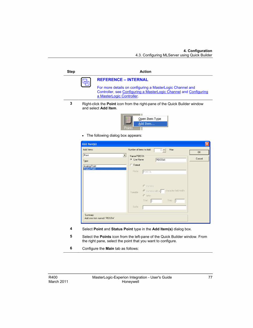
3 Right-click the Point icon from the right-pane of the Quick Builder window and select Add Item.
• The following dialog box appears:
4 Select Point and Status Point type in the Add Item(s) dialog box.
5 Select the Points icon from the left-pane of the Quick Builder window. From the right pane, select the point that you want to configure.
6 Configure the Main tab as follows:

4. Configuration 4.3. Configuring MLServer using Quick Builder
78 MasterLogic-Experion Integration User's Guide R400 Honeywell March 2011
Step Action
7 Enter the Parent Asset for the point. All Alarms/Events raised by Experion is in this Asset.
TIP
Honeywell recommends that the Parent Asset configured here must be the same as the EPKS Asset Name configured in the MLServer Configuration Tool for the PLC referred in this point.
8 Select ellipse button next to PV Source Address.
• The Address Builder dialog box appears.
9 Select Controller from Address Type drop-down list and appropriate Controller name from Controller drop-down list. Enter PLC Point name in Location.
Note: The PLC Point name includes the PLC ID, memory area, command, and data type. The name of the user-defined data format is also provided in the PLC Point name.

4. Configuration 4.3. Configuring MLServer using Quick Builder
R400 MasterLogic-Experion Integration - User's Guide 79 March 2011 Honeywell
Step Action
REFERENCE - INTERNAL
• For more details on PLC Point name, see PLC Point configuration details.
• For more details on user-defined data format, see Defining data formats.
10 Configure the Control tab as follows:
11 Enter Output’s Source Address and Dest Address through Address Builder dialog box. (Optional)
Note:
• Output Source Address: This denotes the address from where OP reads the associated parameter value that can be viewed in the Experion Station.
• Output Dest Address: The value written to OP is transferred to this location in the PLC.
12 Select the Scan Period for OP.
Note: This represents the interval at which the OP parameter’s value is updated from the PLC Address specified in OP Source Address.

4. Configuration 4.3. Configuring MLServer using Quick Builder
80 MasterLogic-Experion Integration User's Guide R400 Honeywell March 2011
Step Action
WARNING
The Scan Period,
− Must be less than the Background Scan Period configured for the MasterLogic Channel.
− Must not be equal to 0.
TIP
The value for Output need not be defined for every Experion point.
REFERENCE – EXTERNAL
For more details on adding and configuring Points, see Experion Knowledge Builder > Experion PKS R400 > Configuration > Quick Builder Guide > Point Properties.
PLC Point configuration details
WARNING
Honeywell does not recommend modifying the QB database when MLServer is executing. After modifying QDB, restart MLServer by disabling and enabling the MLchannel.
The PLC Point name configured in Quick Builder provides a way of addressing the location in PLC where the values are stored. The PLC Point name specifies the PLC ID, memory address, the command to be executed, and the data type. For example, ML01.%MW95$CON. The PLC Point name entered in the Source Address of Quick Builder for the Analog/Status Points is used for reading PLC data. The PLC Point name entered in the Dest Address is used for writing data into the PLC.
After downloading standard Points to Experion, enable the Channel, Controller and Points from the Experion Station. This triggers off connections to the MLServer based on the configured Channel, Controllers and Points. The MLServer then starts reading from or writing into PLCs using the commands embedded in the PLC Point name.
This section describes the various PLC Point name formats supported in ML200 IEC , ML200R and the commands used for reading or writing PLC information.

4. Configuration 4.3. Configuring MLServer using Quick Builder
R400 MasterLogic-Experion Integration - User's Guide 81 March 2011 Honeywell
The following are the list of PLC Point name formats supported in ML200 R, ML200:
Table 4.3-1: PLC Point name formats supported in ML200R, ML200-IEC
PLC Point Name Format ML200R ML200-IEC
Direct Variable
The following table lists the different memory areas supported in ML200R and its associated data type, range and read/write property:
Table 4.3-2: Memory areas supported in ML200R
MemoryArea
BIT
BYT
E
WO
RD
DW
OR
D
LWO
RD
INT
DIN
T
LI N
T
Range
Rea
dabl
e/W
ritab
le
Low High
I 00.00.00 127.15.63 R
Q 00.00.00 127.15.63 R/W
M 00000 131071F R/W
L 00000 11263F R/W
F 00000 2047F R
R 00000 32767 R/W
U 00.00.000
31.15.511 R/W
W 00000 65535 R/W
Note: The R and W memory areas refer to the same storage locations for the first 32767 words. For example, %RW10 and %WW10 is referring to the same PLC memory address and therefore always have the same value.

4. Configuration 4.3. Configuring MLServer using Quick Builder
82 MasterLogic-Experion Integration User's Guide R400 Honeywell March 2011
The following table lists the different memory areas supported in ML200-IEC and its associated data type, range and read/write property:
Table 4.3-3: Memory areas supported in ML200-IEC
MemoryArea
BIT
BYT
E
WO
RD
DW
OR
D
LWO
RD
INT
DIN
T
LI N
T
Range
Rea
dabl
e/W
ritab
le
Low High
I 00.00.00 127.15.63 R
Q 00.00.00 127.15.63 R/W
M 00000 131071F R/W
L 00000 11263F R/W
F 00000 2047F R
R 00000 32767 R/W
U 00.00.0 3F.31.F R/W
W 00000 65535 R/W
Note: The R and W memory areas refer to the same storage locations for the first 32767 words. For example, %RW10 and %WW10 is referring to the same PLC memory address and therefore always have the same value.

4. Configuration 4.3. Configuring MLServer using Quick Builder
R400 MasterLogic-Experion Integration - User's Guide 83 March 2011 Honeywell
The following table lists the various commands supported in ML200/ML200R:
Table 4.3-4: Commands supported in ML200R/ML200-IEC
Commands Read Write Remarks
CON (ML200/ML200R)
Continuous Read command
If the PLC Point name ML01.%MW002$CON and ML01.%MW\K004$CON#REAL are passed for read, a single Continuous Read command is used for reading the 2nd and 4th Word of M memory area from PLC 01.
Continuous Write command
If value is written to a Point’s parameter that is configured as ML01.%MW002$CON and ML01.%MW004$CON#REAL a single Continuous Write command is used for writing the 2nd and 4th Word of M memory area in PLC 01.
Advantages:
1) Useful when contiguous memory addresses need to be read from the PLC. Up to 1400 bytes can be read / written in a single packet. However, multiple CON packets can be created serving more number of points.
2) This is the recommended method for ML200 when some continuous memory locations need to be read from PLC.
Disadvantages:
This command is not useful when a number of variables need to be read, where
• the addresses are not contiguous or
• belong to different memory areas

4. Configuration 4.3. Configuring MLServer using Quick Builder
84 MasterLogic-Experion Integration User's Guide R400 Honeywell March 2011
Commands Read Write Remarks
DEV (ML200 IEC/ML200R)
Device Area Read
If the PLC Point name ML01.%MW95$DEV is passed for read, the Device Area Read command is used for reading the 95th Word of M memory area from PLC 01.
Device area read is also used to configure DISOE module points. For example, ML01.U1.0.0$DEV#BIT@SOE. Here, device area read is used for reading 1st bit of U1.0.0 word.
Device Area Write
If value is written to a Point‘s parameter that is configured as ML01.%MW95$DEV, the Device Area Write command is used for writing the 95th Word of M memory area in PLC 01.
Advantages:
This command is useful for reading/writing a few variables from/to different memory areas of the PLC. It reads/writes up to 80 variables in a single packet. However, multiple DEV packets can be created serving more number of points.
Disadvantages:
It is not useful for a larger number of variables. (For example: 500 variables.)
Note:
• A single Continuous Read/Write command is used for reading or writing data together for multiple addresses within the same memory area.
• In ML200/ML200R, the maximum number of bytes read/written is 1400.
• The examples given in the previous table refer to ML200.

4. Configuration 4.3. Configuring MLServer using Quick Builder
R400 MasterLogic-Experion Integration - User's Guide 85 March 2011 Honeywell
ATTENTION
• The default command in ML200/ML200R is Device Area Read/Write.
TIPS
Honeywell recommends to use the commands in the following order:
a) CON: First try to use the CON (Continuous Read/Write) command. This is particularly useful when there are a lot of contiguous memory addresses that need to be read from / written to one or two PLC memory.
b) DEV (Only for ML200/ML200R): This command must be used when data from different memory areas needs to be read and also for less number of points.
c) There is no limit on the number of points that can be configured.

4. Configuration 4.3. Configuring MLServer using Quick Builder
86 MasterLogic-Experion Integration - User's Guide R400 Honeywell March 2011
Direct Variable
The following figure depicts the Direct Variable format:
Figure 4.3-1: Direct Variable
• PLCID: This refers to the PLC. It is a two digit number ranging from 01 through 99 and always prefixed by ML. This must be configured in MLServer Configuration Tool.
• MemoryAddress: This refers to the address within the PLC memory area where information is stored.
Format: %<MemoryArea><DataType><Offset>
− In ML200-IEC, for I and Q memory areas <Offset> are <Base>.<Slot>.<Position>. For other areas, it represents the address within the memory area.
REFERENCE – INTERNAL
For more details on memory areas supported in ML200R, see Table 4.3-2.
For more details on memory areas supported in ML200-IEC, see Table 4.3-3.
• Command Type: This refers to the different commands used for reading/writing data from/to PLC by MLServer. For more details on command types, see Table 4.3-4.
• Data Type: This refers to the PLC data type.

4. Configuration 4.3. Configuring MLServer using Quick Builder
R400 MasterLogic-Experion Integration User's Guide 87 March 2011 Honeywell
ATTENTION
Only the following combinations of data types can be used in a Direct Variable.
Data type in Memory Address
Data type at the end of the PLC point name (after #)
X BIT
B BYTE
W WORD and INT
D DWORD, DINT and REAL
L LWORD, LINT and LREAL
The request is sent to PLC with the data types configured in the memory address part (that is X, B, W, D and L) of the PLC point name. After receiving the responses, the MLServer converts it to the data type configured after #.
If no data type is configured in the PLC point name (that is no # part), by default the corresponding basic data type is used by the MLServer. For example, if the PLC point is configured as ML01.%MW90$CON, then it would be assumed as ML01.%MW90$CON#WORD.
The following table contains a list of examples for Direct Variable:
Table 4.3-5: Examples of Direct Variable
Direct Variable
Note: In the following examples, ML01 is a ML200-IEC PLC. The bit / word positions are 0-based.
Examples • ML01.%MB105$CON – This denotes the 1st Byte of the 53rd Word in the Internal memory area of PLC ML01. Continuous Read / Write is used for communication with PLC.
• ML01.%IW2.3.1$CON#INT – This denotes the 1st word in 3rd slot of Base2 in the Input memory area of PLC ML01. Continuous command is used for getting values from the PLC. The data is converted by MLServer and available as a signed integer value on the Experion side.

4. Configuration 4.3. Configuring MLServer using Quick Builder
88 MasterLogic-Experion Integration User's Guide R400 Honeywell March 2011
Direct Variable
Note: In the following examples, ML01 is a ML200-IEC PLC. The bit / word positions are 0-based.
• ML01.%RD80$CON#REAL – This denotes the 80th double word (that is 160th and 161st words) in R memory area of PLC ML01. The Continous command is used for communication with the PLC. The data is converted by MLServer and available as a decimal (or REAL) value on the Experion side.
Defining data formats
Data formats are defined for converting PLC field values into engineering values. Experion provides default data formats for converting these field values. You also can define customized data formats.
REFERENCE - EXTERNAL
For more details on user-defined data formats, see Experion Knowledge Builder > Experion PKS R400 > Configuration > Server and Client Configuration Guide > Understanding and configuring points > Advanced point configuration > Creating user-defined data formats.
To create a customized data format, perform the following:
TIP
The following is a sample procedure explaining how to create a user-defined data format.

4. Configuration 4.3. Configuring MLServer using Quick Builder
R400 MasterLogic-Experion Integration User's Guide 89 March 2011 Honeywell
Step Action
1 Select System Configuration menu from the Experion Station.
2 Select User-Defined Data Formats in Application Development.
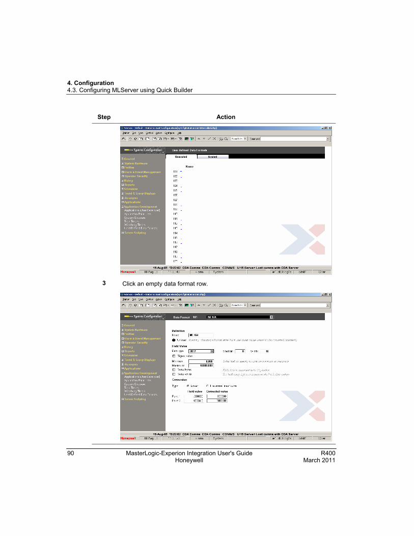
4. Configuration 4.3. Configuring MLServer using Quick Builder
90 MasterLogic-Experion Integration User's Guide R400 Honeywell March 2011
Step Action
3 Click an empty data format row.

4. Configuration 4.3. Configuring MLServer using Quick Builder
R400 MasterLogic-Experion Integration User's Guide 91 March 2011 Honeywell
Step Action
4 Enter data format name in Name.
5 Select data type from Data Type drop-down list. For Example INT2.
6 Enter the minimum and maximum field values in Minimum and Maximum. For Example 0 and 16000 respectively.
7 Enter Field value and corresponding Converted value for Point 1 and Point 2 to define the conversion. For Example 0 and 1000 respectively.
Example: If the field value is 8000, the corresponding converted value must be 500.
ATTENTION
While configuring the Points in Quick Builder,
If 100% Range value is… Converted value ranges from…
1000 0 to 1000
100 0 to 100
The following table describes some sample field values and their corresponding engineering values in Experion:
Input
Range Data Format Field
value PLC
value Engineering
value (Converted
value) PLC Engineering
0 to 5 volts
Minimum: 0
Maximum: 16000
Point 1: 0
Point 2: 1000
2.5 volts
8000 500
1 to 5 volts
Minimum: 0
Maximum: 16000
Point 1: 0
Point 2: 1000
2 volts
4000 250

4. Configuration 4.4. Downloading Quick Builder Points to Experion
92 MasterLogic-Experion Integration User's Guide R400 Honeywell March 2011
4.4 Downloading Quick Builder Points to Experion Overview
After adding and configuring items, you must download all or part of your project to the server database. The Channel, Controller or Point that have been imported or manually created in Quick Builder must be downloaded to Experion server database before you can use them.
The items are downloaded in the following sequence:
• MasterLogic Channel.
• MasterLogic Controller(s).
• Analog/Status Point(s).
REFERENCE – EXTERNAL
For more details on downloading items to Experion, see Experion Knowledge Builder > Experion PKS R400 > Configuration > Quick Builder Guide > Managing items > Downloading items.
After downloading, the MasterLogic Channel and MasterLogic Controller are enabled in the Experion Station using View > System Status > Channels.

4. Configuration 4.5. Verifying the configuration
R400 MasterLogic-Experion Integration User's Guide 93 March 2011 Honeywell
4.5 Verifying the configuration Overview
After downloading Points to the Experion, enable the Channel and Controller from the Experion Station.
After enabling the Channel and Controller, the following events occur:
• The MasterLogic server starts communicating with the PLCs using the configuration information from the Experion server database. A connection is established with the MLServer based on the Channel configuration.
• MLServer establishes communication with the PLCs using the IP Address & other PLC specific details configured using the configuration tool.
• The MLServer reads data from the PLC and transfers the values to the corresponding parameters in Experion Points. The data values written into these parameters are written into the appropriate memory locations in the PLC.
• Based on the status of the PLCs, the alarms/events are raised by the MLServer, in the Experion.
• The data, alarms raised by the PLCs and change of event in the PLCs can be monitored from the Experion Station.
You must ensure that PLCs are configured with correct IP address.
Verifying data exchange between PLC and Experion The Point Detail display in the Experion Station helps in monitoring the online status of each parameter for a particular Point and the data exchange between the PLC and the Experion server.
• The parameter values set in the Point Detail display reflects in the Address monitoring window of the SoftMaster tool.
• The parameter values set in the Address monitoring window reflects in the Experion station.

4. Configuration 4.5. Verifying the configuration
94 MasterLogic-Experion Integration User's Guide R400 Honeywell March 2011
The following procedure is an example to verify data exchange between the PLC and the Experion:
Step Action
1 Configure the PLC information using the MLServer Configuration Tool.
2 Ensure that the ML16K user defined data format is configured in Experion.
3 Configure the MasterLogic Channel, MasterLogic Controller, Status and Analog Point in the Quick Builder and download to the Experion Server.
Note: Consider a standard Analog Experion Point configured in Quick Builder as follows:
• PV source address as ML01.%MW10$DEV ML16K
• SP source and destination address as ML01.%MW80$DEV ML16K
The user-defined data format ML16K is used here to convert between the field value (0 to 16000) and the engineering value (0 to 1000).
4 Download the MasterLogic Channel, MasterLogic Controller and Point to the Experion Server.
5 Enable the Channel from the Channel Summary page in the Station.
• The MasterLogic Server starts communicating with the PLC using the configuration information.
• The MasterLogic Server reads data from the PLC and transfers the values to the corresponding parameters in Experion Points. The data values written into these parameters are written into the appropriate memory locations in the PLC.

4. Configuration 4.5. Verifying the configuration
R400 MasterLogic-Experion Integration User's Guide 95 March 2011 Honeywell
Step Action
• Assume that the data value stored in the 10th word of M memory area is 8000. The following image shows the value displayed in the Address Monitoring window of the SoftMaster tool:

4. Configuration 4.5. Verifying the configuration
96 MasterLogic-Experion Integration User's Guide R400 Honeywell March 2011
Step Action
The raw value (8000) is converted to the engineering value (500) because of the ML16K data format and updated in the PV parameter. This value is displayed in the Station as shown in the following image:
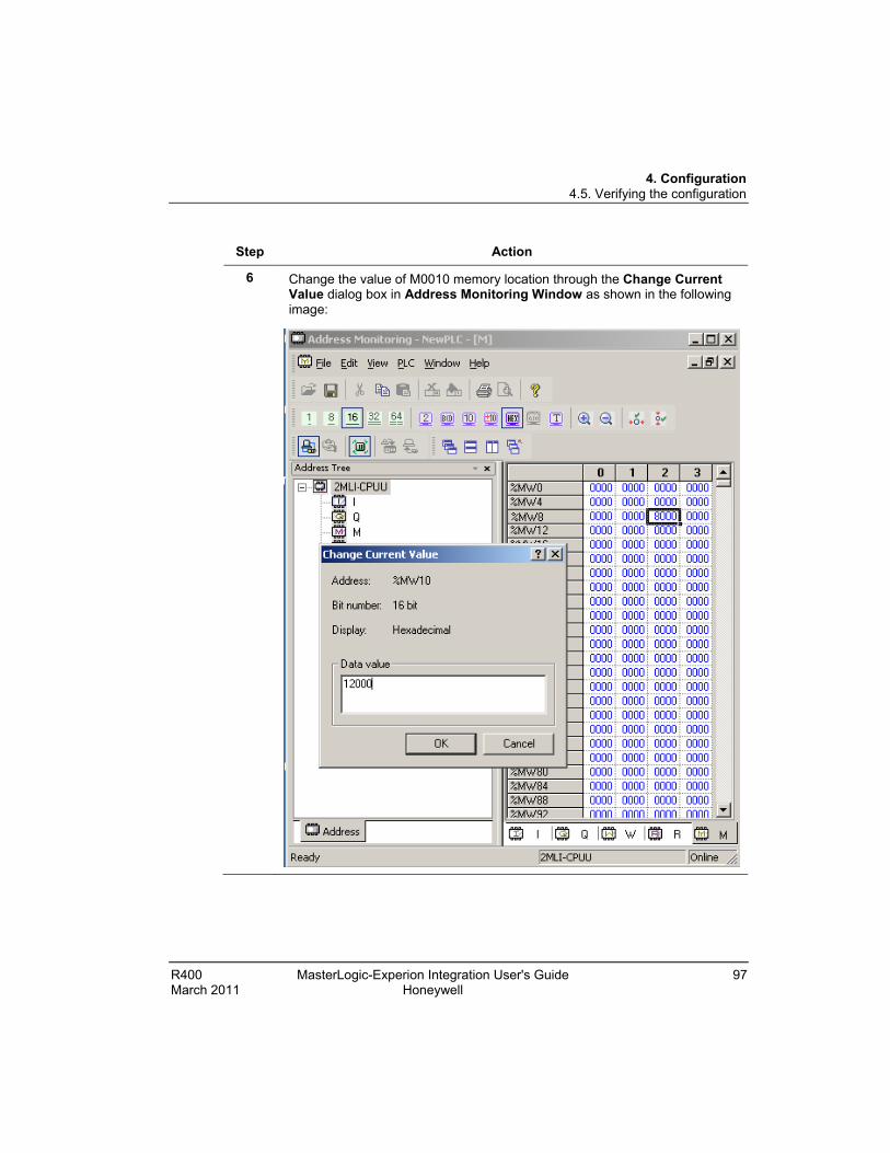
4. Configuration 4.5. Verifying the configuration
R400 MasterLogic-Experion Integration User's Guide 97 March 2011 Honeywell
Step Action
6 Change the value of M0010 memory location through the Change Current Value dialog box in Address Monitoring Window as shown in the following image:

4. Configuration 4.5. Verifying the configuration
98 MasterLogic-Experion Integration User's Guide R400 Honeywell March 2011
Step Action
The raw value (12000) is converted to the engineering value (750) because of the ML16K data format and updated in the PV parameter. This value is displayed in the Station as shown in the following image:

4. Configuration 4.5. Verifying the configuration
R400 MasterLogic-Experion Integration User's Guide 99 March 2011 Honeywell
Step Action
7 Set a value 250 to SP parameter in the Station as shown in the following image:

4. Configuration 4.5. Verifying the configuration
100 MasterLogic-Experion Integration User's Guide R400 Honeywell March 2011
Step Action
The engineering value (250) is converted to the raw value (4000) and updated in the %MW80 memory location. This can be observed in the Address Monitoring window of the SoftMaster tool as shown in the following image:
R400 MasterLogic-Experion Integration - User's Guide 101 March 2011 Honeywell
5. Monitoring PLC status from Experion displays
5.1 Overview Experion displays
The Experion standard Station displays and the Custom displays are used for monitoring the PLC status.
The following are the Experion standard Station displays:
• Channel Summary page
• Point Detail display
The following is the Experion Custom display:
• PLC System Status display
ATTENTION
To view the PLC information in the graphics pages, ensure that the points corresponding to the PLCs are configured using the Point Build utility.

5. Monitoring PLC status from Experion displays 5.2. Building a Point in Experion corresponding to the PLC
102 MasterLogic-Experion Integration User's Guide R400 Honeywell March 2011
5.2 Building a Point in Experion corresponding to the PLC Using Configuration tool
The information required by the Experion Graphics is stored in the user-defined parameters of Experion points configured for each PLC. These PLC level Points are built by enabling the Auto Point Build option in ML Server Configuration Tool. If these points are not built, then the data communication between the MLServer and Experion does not appear in the Experion custom displays.
To build Points for the configured PLCs, perform the following steps:
Step Action
1 Configure the PLC information using the MLServer Configuration Tool, for each PLC with which the MLServer must communicate. Ensure that EPKS Asset Name is configured in the tool.
REFERENCE – INTERNAL
For more information about configuring the PLC information, see Configuring PLC Information.

5. Monitoring PLC status from Experion displays 5.2. Building a Point in Experion corresponding to the PLC
R400 MasterLogic-Experion Integration User's Guide 103 March 2011 Honeywell
Step Action
2 Select the Auto Point Build option.
3 Click Save Configuration.
4 The output files with extension .out and .pnt are created.
For example:
• The MLPLC_StatusPoints.pnt file is created. This file contains the information about the points to be built in Experion corresponding to the selected PLCs.
• The MLPLC_StatusPoints.out file shows the status of Point building.

5. Monitoring PLC status from Experion displays 5.2. Building a Point in Experion corresponding to the PLC
104 MasterLogic-Experion Integration User's Guide R400 Honeywell March 2011
Step Action
5
ATTENTION
If there is an error during point building the following message appears:
Restart MLServer for any configuration changes to take effect.
ATTENTION
Restart the MLServer for the configuration changes to take effect.

5. Monitoring PLC status from Experion displays 5.3. Using Experion custom displays
R400 MasterLogic-Experion Integration User's Guide 105 March 2011 Honeywell
5.3 Using Experion custom displays PLC System Status Display
The PLC information is displayed in the Experion Station using custom displays.
The following are the three tabs available in the custom displays used for viewing the PLC information:
Tab name File name Description
Config Info MLPLC_Config.htm This page displays the basic PLC information and diagrammatic representation of the modules with base/slot information.
Status Info MLPLC_Status.htm This page displays the PLC status diagnostics information.
Driver Info MLPLC_Driver.htm This page displays the MLServer interface driver diagnostics information.
Config Info
The Config Info page is used for monitoring the base slot information of each PLC and the status of communication between the PLC and the Experion server.
The following PLC information appears in the Config Info page:
• PLC Name
• PLC ID
• PLC Type
• Base number
• Last RTC time
• Diagrammatic representation of the modules with base/slot information

5. Monitoring PLC status from Experion displays 5.3. Using Experion custom displays
106 MasterLogic-Experion Integration User's Guide R400 Honeywell March 2011
To view the general PLC and base/slot information in the Experion display, perform the following steps:
Step Action
1 Ensure the Auto Point Build check box in Config tool is enabled.
2 Click Start > Programs > Honeywell MasterLogic Server > Configuration Tool and select the PLC.
3 Select EPKS Write and IO Read check boxes under Monitor using the MLServer Configuration Tool.
4 Invoke the Experion Station.
5 Enter MLPLC_config.htm in the Command zone. Press Enter.

5. Monitoring PLC status from Experion displays 5.3. Using Experion custom displays
R400 MasterLogic-Experion Integration User's Guide 107 March 2011 Honeywell
Step Action
• The following page appears for ML 200R:
6 Select the name of a PLC from the PLC dropdown list.
• The PLC ID, PLC Type, Base, IP Addresses and Last RTC Read Time are displayed.
Note: All the fields in the page (except the PLC Name and Base Number) are not editable. The IP Address indicated in green is the active IP Address.
7 Select base number from the Base dropdown list.
Note: Base 0 is selected by default.
The following information is displayed diagrammatically:
• CPU status
• Different slots of the selected base.

5. Monitoring PLC status from Experion displays 5.3. Using Experion custom displays
108 MasterLogic-Experion Integration User's Guide R400 Honeywell March 2011
Step Action
The following information appears in 3 columns in the lower part of the window:
• The Name column indicates the slot position and module name.
• The Assigns Information column indicates the module information.
• The Description column indicates the module description.
Viewing RTC time in Config Info page
The PLC time must be synchronized with the Experion system time. The MLServer reads the PLC time and compares with the Experion system time, based on the settings in MLServer Configuration Tool. If there is a time difference, the PLC time is updated with the Experion system time. The RTC time read from the PLC is displayed in the Config Info graphics page.
The following figure depicts how the PLC time is synchronized with the Experion system time:
To view the RTC time in the Config Info page, perform the following steps:
Step Action
1 Click Start > Programs > Honeywell MasterLogic Server > Configuration Tool and select the PLC.

5. Monitoring PLC status from Experion displays 5.3. Using Experion custom displays
R400 MasterLogic-Experion Integration User's Guide 109 March 2011 Honeywell
Step Action
2 Select EPKS Write under Monitor and Enable Read/Write under RTC using the MLServer Configuration tool.
3 Enter SynchInterval under RTC.
Note: This indicates the time frequency for reading the RTC time from the PLC. If this value is 0 then the RTC time is not read or written from/to the PLC.
4 Enter Deadband under RTC.
Note: The PLC time is updated with the Experion system time, if the time difference is equal to or greater Deadband (in seconds). If this value is 0 then the RTC time is not written to the PLC.
• The RTC time is displayed in the Config Info page as shown in the following figure:
Status Info
The Status Info page is used for monitoring the online status of each PLC, the MLServer and the data exchange between the PLC and the Experion server.
• The parameter value for the PLC status set in the xml files is used for updating the PLC status information in the Experion graphics pages.

5. Monitoring PLC status from Experion displays 5.3. Using Experion custom displays
110 MasterLogic-Experion Integration User's Guide R400 Honeywell March 2011
To verify the PLC status information updates in the Experion graphics pages, perform the following steps:
Step Action
1 Ensure the Auto Point Build check box in Config tool is enabled.
2 Click Start > Programs > Honeywell MasterLogic Server > Configuration Tool and select the PLC.
3 Select EPKS Write and Status Read check boxes under Monitor using the MLServer Configuration tool.
• The status of the CPU operation mode is updated in the Experion graphics display.
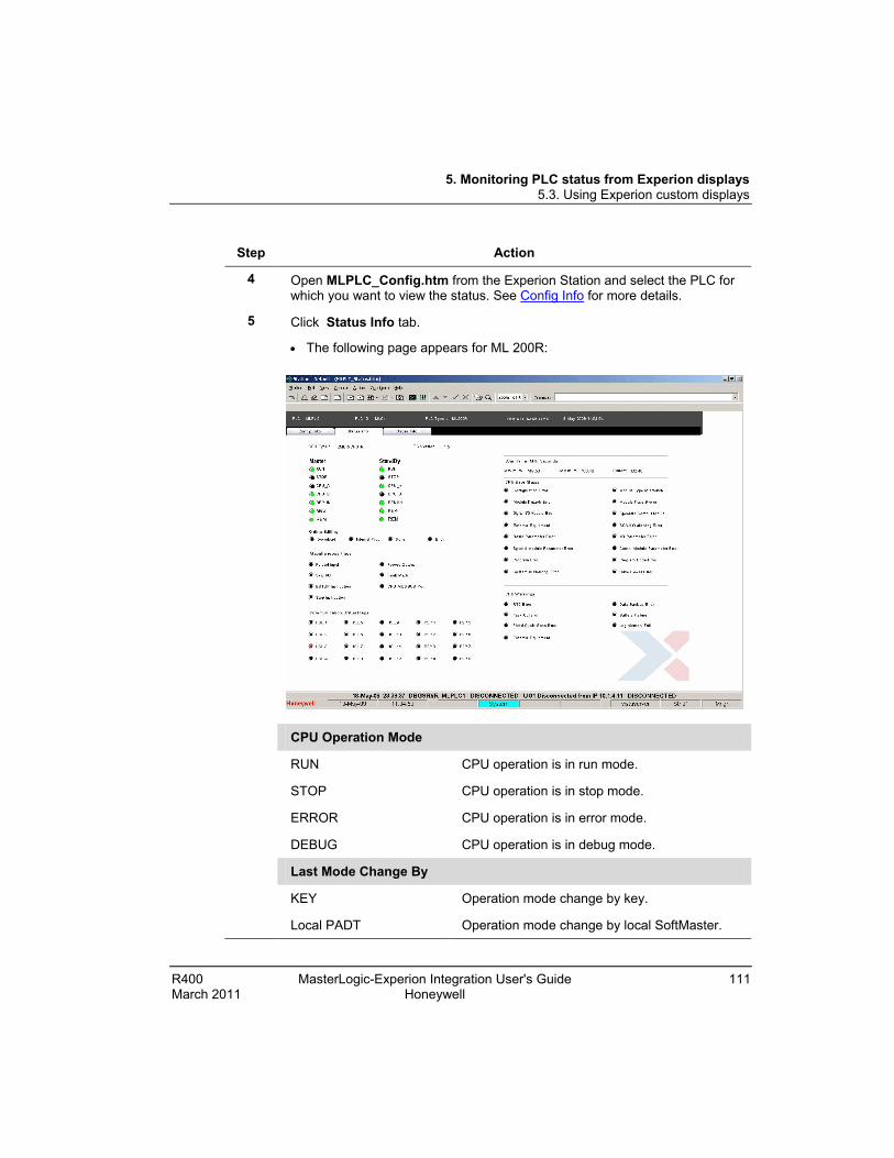
5. Monitoring PLC status from Experion displays 5.3. Using Experion custom displays
R400 MasterLogic-Experion Integration User's Guide 111 March 2011 Honeywell
Step Action
4 Open MLPLC_Config.htm from the Experion Station and select the PLC for which you want to view the status. See Config Info for more details.
5 Click Status Info tab.
• The following page appears for ML 200R:
CPU Operation Mode
RUN CPU operation is in run mode.
STOP CPU operation is in stop mode.
ERROR CPU operation is in error mode.
DEBUG CPU operation is in debug mode.
Last Mode Change By
KEY Operation mode change by key.
Local PADT Operation mode change by local SoftMaster.

5. Monitoring PLC status from Experion displays 5.3. Using Experion custom displays
112 MasterLogic-Experion Integration User's Guide R400 Honeywell March 2011
Step Action
Remote PADT Operation mode change by remote SoftMaster.
Remote Comn. Operation mode change by remote communication module.
Local / Remote
Local Operation mode change only by mode key.
Remote Remote mode operation.
Online Editing
Download Revised program stand-by when revising on the run.
Internal Proc Revising on the run during internal processing.
Done Revising on the run is completed as normal.
Error Revising on the run is completed as normal.
Miscellaneous Flags
Forced Input Force on/off by input points.
Forced Output Force on/off by output points.
Skip I/O Designated Input/output module for stopping trouble check and data refresh.
Fault Mask Designated Input/output module for proceeding operation even in time of trouble.
Monitor Mode External monitor running for program and variables.
CPU MODBUS Port CPU Mode bus slave service is active.
Stop Instruction Stop after scan completion by STOP function during RUN mode operation.
ESTOP Instruction Immediate stop by ESTOP function during RUN mode operation.
Scan Time (Milli Seconds)
Maximum Maximum PLC CPU scan period.
Minimum Minimum PLC CPU scan period.

5. Monitoring PLC status from Experion displays 5.3. Using Experion custom displays
R400 MasterLogic-Experion Integration User's Guide 113 March 2011 Honeywell
Step Action
Current Current PLC CPU scan period.
CPU Error Status
Configuration Error Normal operation is impossible because of the CPU module self-diagnosis error.
Module Detach Error When actual module and each slot I/O configuration parameter are not matched.
Digital I/O Module Error When each slot module’s input/output module cannot normally read and write this error is displayed.
External Equipment External equipments serious trouble written in ANC_ERR[n] is shown by user program.
Module Type Mismatch When actual module and each slot I/O configuration parameter are not matched.
Module Fuse Blown When each slot module with fuse is short, this error is displayed.
Special / Comn. Module When interface does not work because of special or communication module’s malfunction its error is displayed.
SCAN Watchdog Error When scan watchdog time is exceeded because of its parameter.
Basic Parameter Error Basic parameter error is checked and displayed.
I/O Parameter Error When each slot module’ s input/output module cannot normally read and write this error is displayed.
Comn. Module Parameter Error
Communication module parameter error is checked and displayed.
Program Code Error User program error is checked and displayed.
Base Power Error Base power error.
CPU Warnings
RTC Error RTC data error.

5. Monitoring PLC status from Experion displays 5.3. Using Experion custom displays
114 MasterLogic-Experion Integration User's Guide R400 Honeywell March 2011
Step Action
Task Collision An identical task is double-requested during user program running; the collision with the previous task is displayed.
Fixed Cycle Scan Error If scan time is longer than the designated ‘fixed cycle’, it becomes ‘ON’.
External Equipment When external equipments’ warning written in ANC_WB[n] by user program, its trouble is displayed.
Data Backup Error Data memory is destroyed because of back-up error and thus, restart program (hot or warm) revision is impossible. Regarding cold restart running, this flag is possible to use for initializing program and is automatically reset once initializing program is completed.
Battery Failure When battery voltage for user program and data memory back-up is below the standard.
Log Memory Full When PLC’s log memory becomes full.
Communication Status Flags
HSL1 They are representative flags when high speed link is impossible after checking each high speed link error on high speed link Enabling situation. If high speed link is disabled, it is reset.
P2P1 They are representative flags when P2P running is impossible after checking each P2P parameter error on P2P Enabling situation. If P2P is disabled, it is reset.
• The CPU Type and OS Version (CPU firmware version) are displayed.
The PLC Status information is displayed in 5 different tabs.
SYS State tab Displays the PLC system operation status.
Slot Info Displays the information for different slots.
PADT_CNF Displays the PADT configuration information.
CNF_ER Displays error messages and status of stopping the operation.

5. Monitoring PLC status from Experion displays 5.3. Using Experion custom displays
R400 MasterLogic-Experion Integration User's Guide 115 March 2011 Honeywell
Step Action
CNF_WAR Displays the warning flags with respect to quick operations.
DOMAIN_ST Displays the information on System software configuration.
ATTENTION
The option of selecting another PLC is not available in Status Info page. To view another PLC’s status, select a PLC name from Config Info page and click Status Info tab.
• The CPU operation in run mode is displayed in the Experion graphics display as shown in the following figure:
6 Click Stop button in the SoftMaster tool or using the keys on the PLC, change the CPU operation mode to stop.

5. Monitoring PLC status from Experion displays 5.3. Using Experion custom displays
116 MasterLogic-Experion Integration User's Guide R400 Honeywell March 2011
Step Action

5. Monitoring PLC status from Experion displays 5.3. Using Experion custom displays
R400 MasterLogic-Experion Integration User's Guide 117 March 2011 Honeywell
Step Action
• The following message appears:
7 Click Yes.
• The CPU operation mode status is updated in the graphics display within few seconds as shown in the following figure:
8 Click in the SoftMaster tool or using the keys on the PLC, change the CPU operation mode to run.
• The following message appears:

5. Monitoring PLC status from Experion displays 5.3. Using Experion custom displays
118 MasterLogic-Experion Integration User's Guide R400 Honeywell March 2011
Step Action
9 Click Yes.
• The CPU operation mode status is updated in the graphics display within few seconds as shown in the following figure:
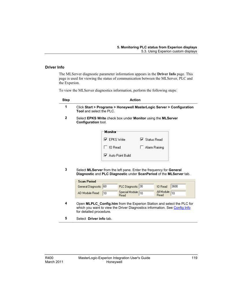
5. Monitoring PLC status from Experion displays 5.3. Using Experion custom displays
R400 MasterLogic-Experion Integration User's Guide 119 March 2011 Honeywell
Driver Info The MLServer diagnostic parameter information appears in the Driver Info page. This page is used for viewing the status of communication between the MLServer, PLC and the Experion.
To view the MLServer diagnostics information, perform the following steps:
Step Action
1 Click Start > Programs > Honeywell MasterLogic Server > Configuration Tool and select the PLC.
2 Select EPKS Write check box under Monitor using the MLServer Configuration tool.
3 Select MLServer from the left pane. Enter the frequency for General Diagnostic and PLC Diagnostic under ScanPeriod of the MLServer tab.
4 Open MLPLC_Config.htm from the Experion Station and select the PLC for which you want to view the Driver Diagnostics information. See Config Info for detailed procedure.
5 Select Driver info tab.
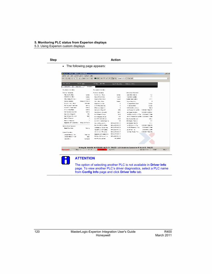
5. Monitoring PLC status from Experion displays 5.3. Using Experion custom displays
120 MasterLogic-Experion Integration User's Guide R400 Honeywell March 2011
Step Action
• The following page appears:
ATTENTION
The option of selecting another PLC is not available in Driver Info page. To view another PLC’s driver diagnostics, select a PLC name from Config Info page and click Driver Info tab.

5. Monitoring PLC status from Experion displays 5.3. Using Experion custom displays
R400 MasterLogic-Experion Integration User's Guide 121 March 2011 Honeywell
The following table lists the MLServer diagnostics parameters displayed in the graphics page:
Parameter Name Description
PLC General Parameters – MLServer Parameters
ML Config XML Status Indicates the status of MLConfig XML read.
ML Monitor XML Status Indicates the status of MLMonitor XML read.
ML AppSettings XML Status Indicates the status of MLAppSettings XML read.
MLServer Start Time Indicates the latest start time of the MLServer.
PSCommunication Status Indicates the status of the communication between the MLServer and Protocol Stack.
Main Response Thread Status Indicates the status of MLServer main response thread.
HCI CallBack Thread Status Indicates the HCI call back thread Status
EPKS Commn Thread Status Indicates the Experion communication thread Status
Main Response Queue Size Indicates MLServer main queue size.
Current Static Request ID Indicates the static Request ID assigned to the command sent to PLC.
Current Dynamic Request ID Indicates the dynamic Request ID assigned to the command sent to PLC.
Number of Requests Indicates number of requests sent to Protocol stack in one second.
Number of Responses Indicates the number of responses received from Protocol stack in one second.
Diagnostics UDP Updated Time Indicates the time when the Diagnostics related Experion UDP parameters were last written by MLServer.
PLC General Parameters – Protocol Stack Parameters
Engine Thread Status Indicates the status of ML protocol engine thread.
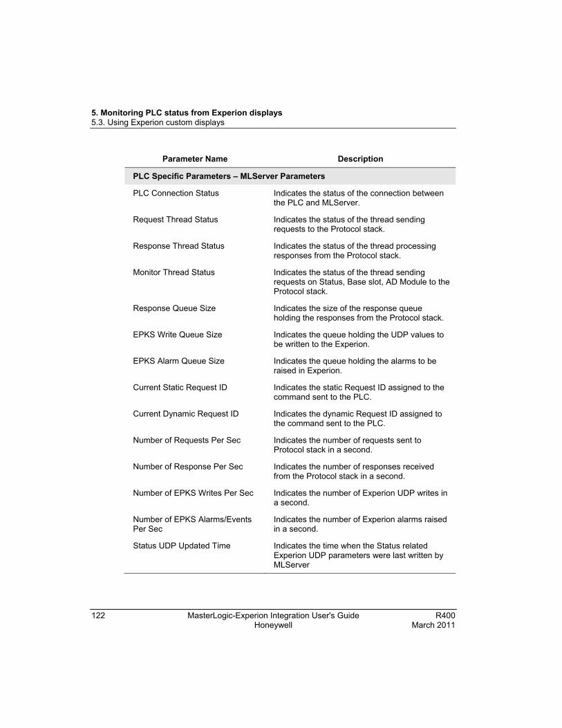
5. Monitoring PLC status from Experion displays 5.3. Using Experion custom displays
122 MasterLogic-Experion Integration User's Guide R400 Honeywell March 2011
Parameter Name Description
PLC Specific Parameters – MLServer Parameters
PLC Connection Status Indicates the status of the connection between the PLC and MLServer.
Request Thread Status Indicates the status of the thread sending requests to the Protocol stack.
Response Thread Status Indicates the status of the thread processing responses from the Protocol stack.
Monitor Thread Status Indicates the status of the thread sending requests on Status, Base slot, AD Module to the Protocol stack.
Response Queue Size Indicates the size of the response queue holding the responses from the Protocol stack.
EPKS Write Queue Size Indicates the queue holding the UDP values to be written to the Experion.
EPKS Alarm Queue Size Indicates the queue holding the alarms to be raised in Experion.
Current Static Request ID Indicates the static Request ID assigned to the command sent to the PLC.
Current Dynamic Request ID Indicates the dynamic Request ID assigned to the command sent to the PLC.
Number of Requests Per Sec Indicates the number of requests sent to Protocol stack in a second.
Number of Response Per Sec Indicates the number of responses received from the Protocol stack in a second.
Number of EPKS Writes Per Sec Indicates the number of Experion UDP writes in a second.
Number of EPKS Alarms/Events Per Sec
Indicates the number of Experion alarms raised in a second.
Status UDP Updated Time Indicates the time when the Status related Experion UDP parameters were last written by MLServer

5. Monitoring PLC status from Experion displays 5.3. Using Experion custom displays
R400 MasterLogic-Experion Integration User's Guide 123 March 2011 Honeywell
Parameter Name Description
Base Slot UDP Updated Time Indicates the time when the Base slot related Experion UDP parameters were last written by MLServer
AD Module UDP Updated Time Indicates the time when the AD Module related Experion UDP parameters were last written by MLServer
Special Module UDP Updated Time
Indicates the time when the Special Module related Experion UDP parameters were last written by MLServer
Miscellaneous UDP Updated Time Indicates the time when the Miscellaneous Experion UDP parameters were last written by MLServer
Diagnostics UDP Updated Time Indicates the time when the Diagnostics related Experion UDP parameters were last written by MLServer
RTC Read UDP Updated Time Indicates the time when the RTC read related Experion UDP parameters were last written by MLServer
RTC Write Updated Time Indicates the time when the RTC write related Experion UDP parameters were last written by MLServer
PLC Specific Parameters – Protocol Stack Parameters
Large Buffers Available Indicates the number of large buffers maintained by Protocol stack.
Small Buffers Available Indicates the number of small buffers maintained by Protocol stack.
Medium Buffers Available Indicates the number of medium buffers maintained by Protocol stack.
Request Queue Size Indicates the size of the request queue maintained by Protocol stack.
PS Request Thread Status Indicates the status of thread that processes requests in Protocol stack.
PS Response Thread Status Indicates the status of thread that processes responses in Protocol stack.

5. Monitoring PLC status from Experion displays 5.3. Using Experion custom displays
124 MasterLogic-Experion Integration User's Guide R400 Honeywell March 2011
Parameter Name Description
PS TB COS Thread Status Indicates the status of thread that processes TB COS responses in Protocol stack.
Last Response Received Time Indicates the time of receiving last response from the PLC socket.
Last Request Sent Time Indicates the time of sending last request to the PLC socket.
Last TB Response Received Time Indicates the time of receiving last TB response from the PLC socket.
Last COS Response Received Time
Indicates the time of receiving last COS response from the PLC socket.
Max Response Time (ms) Indicates the maximum time taken to receive response from PLC.
Min Response Time (ms) Indicates the minimum time taken to receive response from PLC.
Avg. Response Time (ms) Indicates the average time taken to receive response from PLC.
Last PLC Connected Time Indicates the last time when protocol stack was connected to PLC socket.
Last PLC Disconnected Time Indicates the last time when protocol stack was disconnected from PLC socket.
Last HB Sent Time Indicates the last time when Heart Beat message was sent to PLC.
Last Status Received Time Indicates the last time when status response was received from PLC.

5. Monitoring PLC status from Experion displays 5.4. Using Experion standard Station displays
R400 MasterLogic-Experion Integration User's Guide 125 March 2011 Honeywell
5.4 Using Experion standard Station displays Channel Summary page
To enable the ML Channel through Channel Summary page, perform the following steps:
Step Action
1 Invoke the Experion Station.
2 Select View > System Status > Channels.
• The Channel Summary page appears.
3 Select the check box corresponding to the Channel to enable it.
ATTENTION
The Channel status OK corresponds to the communication status between MLServer and Experion server (OPC Communication). It does not correspond to the communication with PLC. If communication is lost with PLC, the alarm for corresponding IP will be raised and all the point status will set in inverted state.
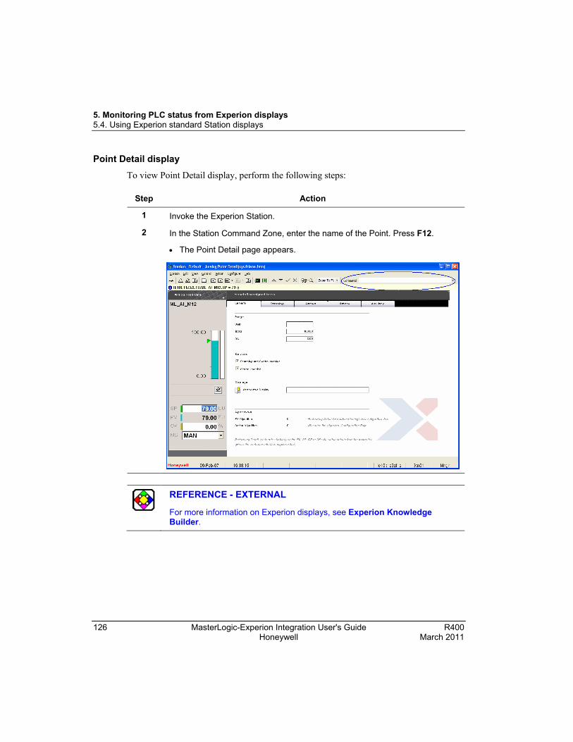
5. Monitoring PLC status from Experion displays 5.4. Using Experion standard Station displays
126 MasterLogic-Experion Integration User's Guide R400 Honeywell March 2011
Point Detail display To view Point Detail display, perform the following steps:
Step Action
1 Invoke the Experion Station.
2 In the Station Command Zone, enter the name of the Point. Press F12.
• The Point Detail page appears.
REFERENCE - EXTERNAL
For more information on Experion displays, see Experion Knowledge Builder.

5. Monitoring PLC status from Experion displays 5.5. Monitoring PLC displays from an Experion client system
R400 MasterLogic-Experion Integration User's Guide 127 March 2011 Honeywell
5.5 Monitoring PLC displays from an Experion client system Overview
The PLC status can be viewed from an Experion client system using the PLC displays. To view the PLC status from an Experion client system, perform the following steps:
Step Action
1 The graphics pages and the xml files must be available in the client system for viewing the PLC information in the client system. If the files are not available, ensure to copy the graphics pages and xml files from the installation path (typically C:\Program Data\Honeywell\Experion PKS\Client\Abstract) to the client system in the same path.
2 The connection properties of the Experion Station must have the folder path C:\Program Data\Honeywell\Experion PKS\Client\Abstract in the list. This allows the viewing of PLC information in the client system.

5. Monitoring PLC status from Experion displays 5.5. Monitoring PLC displays from an Experion client system
128 MasterLogic-Experion Integration User's Guide R400 Honeywell March 2011
Step Action
ATTENTION
To view the PLC status from an Experion client system, the points need not be built using the Point Build utility.
3 To invoke the PLC display pages, follow the procedures explained in Using Experion custom displays.

5. Monitoring PLC status from Experion displays 5.6. Bad quality items
R400 MasterLogic-Experion Integration User's Guide 129 March 2011 Honeywell
5.6 Bad quality items Overview
Experion Point parameters are configured in Quick Builder with PLC Points for data exchange between PLC and Experion. The quality of the Experion Point parameter indicates the status of the data in PLC or the data communication with Experion.
MasterLogic-Experion integration enables the monitoring of analog input signal failures such as transmitter failure or disconnection of input signal. All channels of all analog input modules are constantly monitored for input signal failure. If the input signal fails, all Experion points configured for this input channel is set to BADPV status for safer control of the plant.
The BADPV setting is applicable for the following modules:
Module Type Model# Description
Analog Input module
2MLF-AV8A • Voltage Input: 8 channel
• DC 1 ~ 5V / 0 ~ 5V / 0 ~ 10V / −10 ~ +10V
2MLF-AC8A
• Current Input: 8 Channel
• DC 4 ~ 20mA / 0 ~ 20mA
2MLF-AD8A- • Voltage/Current Input 8 Channel
• DC 1 ~ 5V / 0 ~ 5V / 0 ~ 10V / -10 ~ + 10V 4~20mA/0~20mA
2MLF-AD16A
Voltage/Current Input: 16 channel
DC 1 ~ 5V / 0 ~ 5V / 0 ~ 10V/ -10 ~ + 10V4 ~ 20mA / 0 ~ 20mA
The following explains the two ways of setting quality for the Point parameter:
• Setting quality for Channel disconnection in the field.
• Setting quality for the item based on the PLC Read command responses.

5. Monitoring PLC status from Experion displays 5.6. Bad quality items
130 MasterLogic-Experion Integration User's Guide R400 Honeywell March 2011
Viewing bad quality item in Point Detail display To view the bad quality for Analog Input modules data in the Point Detail display, perform the following steps:
Step Action
1 Click Start > Programs > Honeywell MasterLogic Server > Configuration Tool and select the PLC.
2 Select EPKS Write and IO Read check boxes under Monitor in the configuration tool to view the IO module information in the Experion graphics display. To view PLC status information in Experion graphics display, select Status Read and Alarm Raising check boxes.
3 Consider an IO Module in Base 0 Slot 2 that is also an AD Module and Special Module.
4 Configure the Input Range as 1~5V in the SoftMaster tool. Ensure to write the IO Module configuration to the PLC.

5. Monitoring PLC status from Experion displays 5.6. Bad quality items
R400 MasterLogic-Experion Integration User's Guide 131 March 2011 Honeywell
Step Action
5 Configure a PLC Point as ML01.U01.02.06 in Quick Builder and download to the Experion server.
Note: The PLC point must be configured with U01.02.06, where 01is Base No1, 02 is Slot no 2, and 06 for Channel no 4. This can be identified from the Global variable in SoftMaster.
6 Enable the Channel containing the configured PLC Point.
7 Connect the input signal to Channel 4 (first Channel is 0) of the IO Module.

5. Monitoring PLC status from Experion displays 5.6. Bad quality items
132 MasterLogic-Experion Integration User's Guide R400 Honeywell March 2011
Step Action
• View the status of the data communication in the Station display.

5. Monitoring PLC status from Experion displays 5.6. Bad quality items
R400 MasterLogic-Experion Integration User's Guide 133 March 2011 Honeywell
Step Action
8 Disconnect the input signal from Channel 4.
• View the status of the data communication in the Station display.
Note: The previous example is for Channel 4. If you want to test with a different channel in the IO module, ensure that the data item configured in Experion is also changed appropriately.

5. Monitoring PLC status from Experion displays 5.6. Bad quality items
134 MasterLogic-Experion Integration User's Guide R400 Honeywell March 2011
Step Action
• Alarm is raised corresponding to the disconnected channel with Base number and Slot number as shown in the following figure.

R400 MasterLogic-Experion Integration - User's Guide 135 March 2011 Honeywell
6. Alarms and Events integration
6.1 Alarm integration Types of Alarms
The following are the two types of Alarms raised by the MLServer:
• PLC Status diagnostics Alarms – These alarms are raised based on the current PLC Status.
• Error indicating Alarms / Messages – Important errors that require immediate attention are also raised as System Alarms. The other errors are raised as Messages.
The Asset configured in the PLC tab of the configuration tool, for that particular PLC, is used while generating the Alarms/Events.
PLC Status Diagnostics alarms
After downloading Points to the Experion server, the MLServer starts receiving the status data from the PLC at every configured interval (default is 10 seconds).
Alarms are raised based on the present PLC status. Another PLC level alarm is raised corresponding to the PLC Point if any of the alarming conditions is active at that point of time for the PLC. These alarms can be viewed in the Alarm Summary display of the Experion Station.
ATTENTION
If one or more alarms are raised at the status bit level of a Point, the OP parameter value of the Point is set ON and the corresponding alarm is raised at the PLC level.
Error indicating Alarms / Messages
The important system level error messages such as PLC connection errors are raised as System Alarms in Experion. The less important errors are logged as Messages. This includes errors such as errors in point configuration, and so on.

6. Alarms and Events integration 6.1. Alarm integration
136 MasterLogic-Experion Integration User's Guide R400 Honeywell March 2011
Viewing PLC alarms in Experion Station The Alarms are raised based on the present status of the PLC. A PLC level alarm is raised corresponding to the PLC Point if any of the alarming condition is active at that
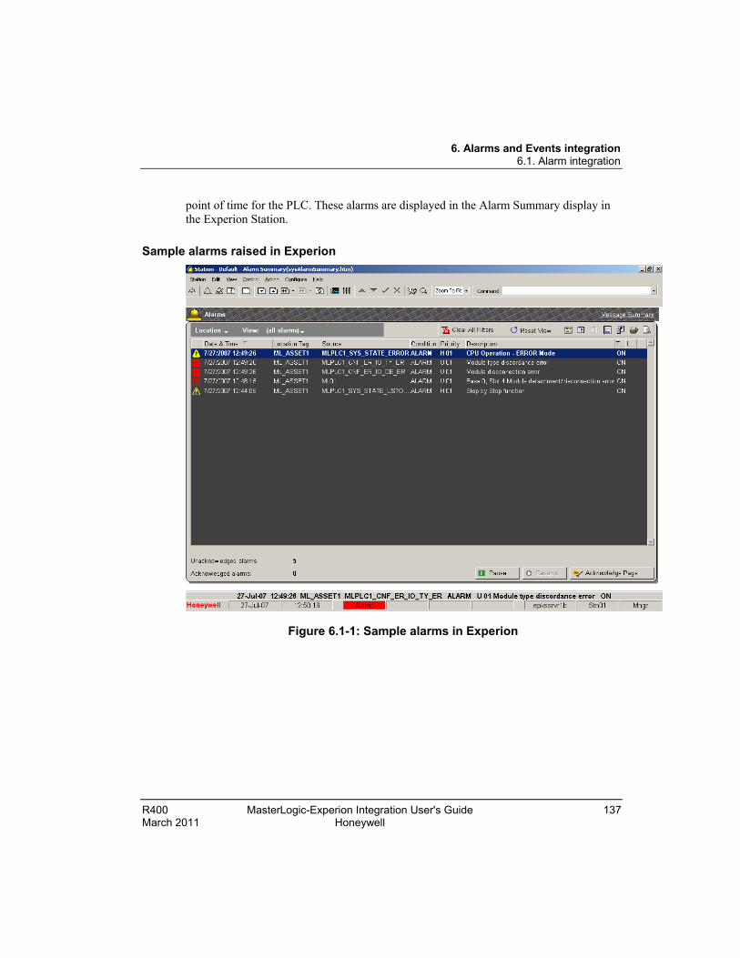
6. Alarms and Events integration 6.1. Alarm integration
R400 MasterLogic-Experion Integration User's Guide 137 March 2011 Honeywell
point of time for the PLC. These alarms are displayed in the Alarm Summary display in the Experion Station.
Sample alarms raised in Experion
Figure 6.1-1: Sample alarms in Experion
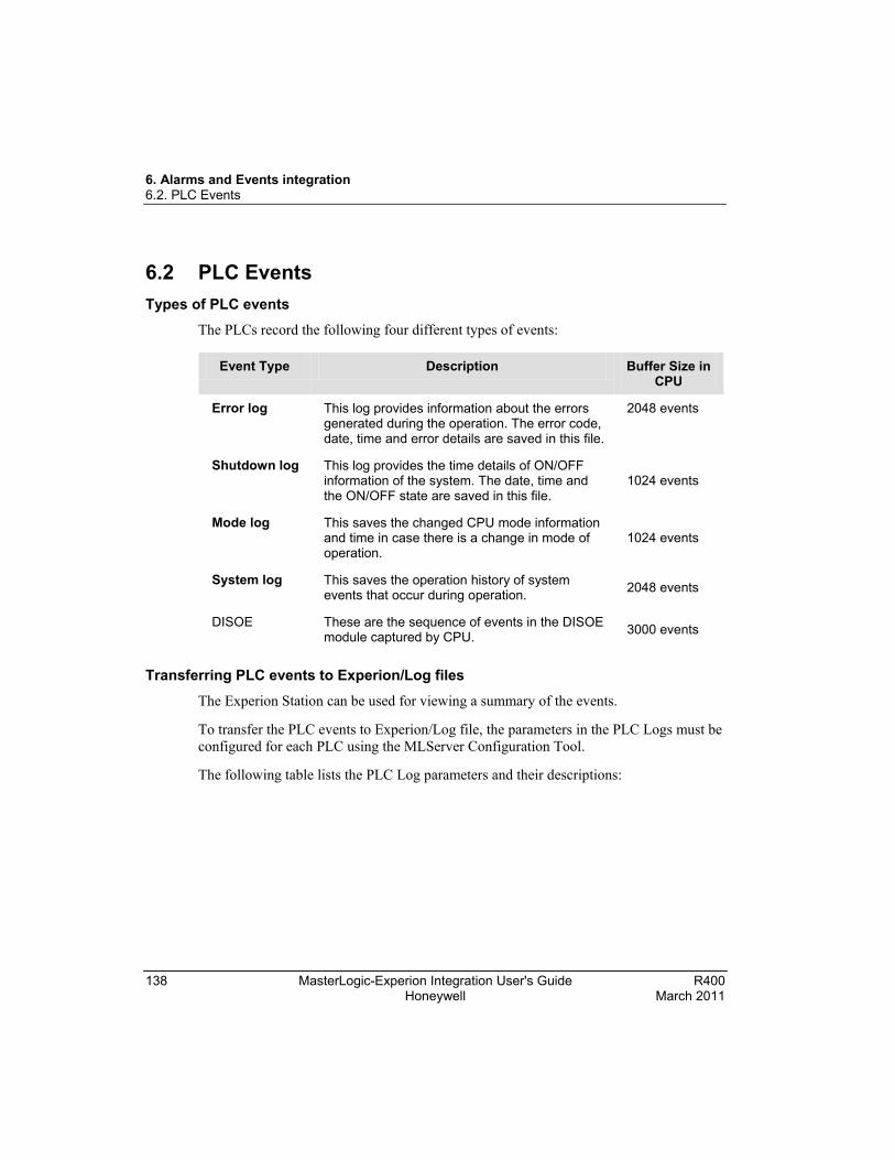
6. Alarms and Events integration 6.2. PLC Events
138 MasterLogic-Experion Integration User's Guide R400 Honeywell March 2011
6.2 PLC Events Types of PLC events
The PLCs record the following four different types of events:
Event Type Description Buffer Size in CPU
Error log This log provides information about the errors generated during the operation. The error code, date, time and error details are saved in this file.
2048 events
Shutdown log This log provides the time details of ON/OFF information of the system. The date, time and the ON/OFF state are saved in this file.
1024 events
Mode log This saves the changed CPU mode information and time in case there is a change in mode of operation.
1024 events
System log This saves the operation history of system events that occur during operation. 2048 events
DISOE These are the sequence of events in the DISOE module captured by CPU. 3000 events
Transferring PLC events to Experion/Log files
The Experion Station can be used for viewing a summary of the events.
To transfer the PLC events to Experion/Log file, the parameters in the PLC Logs must be configured for each PLC using the MLServer Configuration Tool.
The following table lists the PLC Log parameters and their descriptions:

6. Alarms and Events integration 6.2. PLC Events
R400 MasterLogic-Experion Integration User's Guide 139 March 2011 Honeywell
Parameter Possible Values Description
Initial History Enabled/Disabled • If it is Enabled, the already existing PLC events are transferred to Experion server or Log files during startup of the MLServer based on the LogToFile and Events settings.
• If it is Disabled, backlog events are not transferred during the MLServer startup. However the events that occur when the MLServer is running are transferred to Experion server or Log files.
Log To File
Enabled/Disabled If it is Enabled, the PLC events are transferred to log files. These log files are stored in the same folder path used for storing the MLServer log files.
Events Enabled/Disabled If it is Enabled, the PLC events are transferred to Experion server as System Events / Alarms.
ScanPeriod It represents the interval in which the PLC log is scanned for changes and events are logged into the log file and /or Experion server. If this is 0 then the corresponding PLC log is not scanned for changes at all.
After the MLServer starts communicating with the PLCs, depending on the values of these parameters, the events are transferred to the Experion server or the Log files.
The backlog events are saved in the memory area of the respective PLCs. These events can be viewed in the SoftMaster, as shown in the following figure:

6. Alarms and Events integration 6.2. PLC Events
140 MasterLogic-Experion Integration User's Guide R400 Honeywell March 2011
After restarting the MLServer, these events are transferred to the Experion server or log files based on the PLC log parameters settings. To get the backlog of the PLC logs into Experion, the Initial history option could be enabled.
To view a summary of events select View > Events > Event Summary from the Experion Station Display. The following figure depicts the list of events viewed from the Experion Station:
The following figure depicts how the PLC events are transferred to Experion server and are saved in the log files:

6. Alarms and Events integration 6.2. PLC Events
R400 MasterLogic-Experion Integration User's Guide 141 March 2011 Honeywell
Transferring SOE events from PLC to Experion Station
WARNING
Honeywell does not recommend modifying the Quick Builder database when MLServer is executing. After modifying QDB, please restart MLServer by disabling and enabling the MLchannel.
The Experion Station can be used for viewing a summary of the sequence of events generated in the PLC. To transfer the PLC events to Experion/Log file, perform the following steps.
Step Action
1 Connect to PLC with DISOE module using SoftMaster.
2 In the I/O Parameter Setting dialog box, select the SOE module base and slot.
3 Configure the SOE module by selecting the type of events to be captured by the PLC, chattering time and others.
In the I/O Parameter Setting dialog box, double-click the SOE module or click Details.
The SOE Module dialog box appears.
4 Under SOE History, click Reset with recent history option button.

6. Alarms and Events integration 6.2. PLC Events
142 MasterLogic-Experion Integration User's Guide R400 Honeywell March 2011
Step Action
5 In the Basic Parameter Setting dialog box, click Save the latest SOE events option button.

6. Alarms and Events integration 6.2. PLC Events
R400 MasterLogic-Experion Integration User's Guide 143 March 2011 Honeywell
Step Action
6 Ensure Write to PLC after changing these parameters.
7 In Quick Builder, configure a status point in the device area format.
8 Configure a PLC Point as ML01.U1.2.6$DEV#BIT@SOE in Quick Builder and download to the Experion server.
Note: The PLC point must be configured with U1.2.6, where 1 is Base No1, 2 is Slot no 2, and 4 for Channel no 4. Also, @SOE must be added to string at the end to indicate that the point is an SOE module point. You should not configure PLC point as ML01.U01.02.06$DEV#BIT@SOE in Quick Builder.
ATTENTION
All the SOE points must be configured with DEV command and #BIT type. Ensure that base number, slot number, and channel number does not preced with ‘0’.
9 Enable the Channel containing the configured PLC Point.
10 The SOE events are transferred to the Experion server SOE summary page.

6. Alarms and Events integration 6.2. PLC Events
144 MasterLogic-Experion Integration User's Guide R400 Honeywell March 2011
Step Action
11 To view a summary of events, select View > Events > SOE Summary from the Experion Station Display.
The following figure depicts the list of events viewed from the Experion Station.
12 On double-clicking the SOE event, the point’s detailed display page opens.
ATTENTION
DISOE physical I/O points must be configured as SOE SCADA point in Quick Builder to view the corresponding SOE events in Experion Station.

R400 MasterLogic-Experion Integration - User's Guide 145 March 2011 Honeywell
7. Troubleshooting
7.1 MasterLogic Server logs Overview
The MLServer has two modules, the ML Protocol and the MLServer. The modules generate a series of logs, which are useful for various troubleshooting, analysis and recording purposes.
The following is the list of logs generated by the ML Protocol and the MLServer:
• Activity
• Request
• Response
• Trace
• Error
• Hex
• MLMonitor
MLServer logs The Parameters under MLServerLogs to enable/disable the generation of logs are selected using the MLServer configuration tool. The path to store the log files are also configured The LogFolderPath parameter value indicates the path, where the MLServer logs are saved.
The following table explains the logs generated by the MLServer:
Log Optional / Mandatory
Description
Activity Mandatory This log provides general information like MLServer initialization, thread start/stop and successful add item messages.
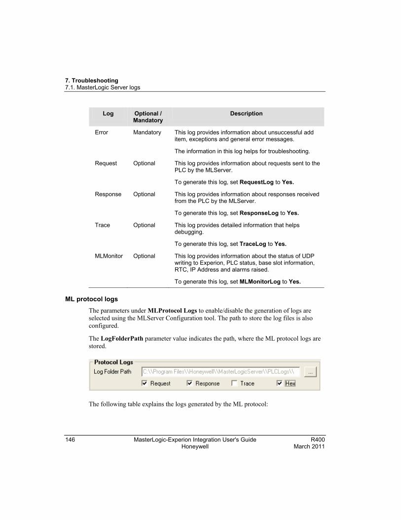
7. Troubleshooting 7.1. MasterLogic Server logs
146 MasterLogic-Experion Integration User's Guide R400 Honeywell March 2011
Log Optional / Mandatory
Description
Error Mandatory This log provides information about unsuccessful add item, exceptions and general error messages.
The information in this log helps for troubleshooting.
Request Optional This log provides information about requests sent to the PLC by the MLServer.
To generate this log, set RequestLog to Yes.
Response Optional This log provides information about responses received from the PLC by the MLServer.
To generate this log, set ResponseLog to Yes.
Trace Optional This log provides detailed information that helps debugging.
To generate this log, set TraceLog to Yes.
MLMonitor Optional This log provides information about the status of UDP writing to Experion, PLC status, base slot information, RTC, IP Address and alarms raised.
To generate this log, set MLMonitorLog to Yes. ML protocol logs
The parameters under MLProtocol Logs to enable/disable the generation of logs are selected using the MLServer Configuration tool. The path to store the log files is also configured.
The LogFolderPath parameter value indicates the path, where the ML protocol logs are stored.
The following table explains the logs generated by the ML protocol:

7. Troubleshooting 7.1. MasterLogic Server logs
R400 MasterLogic-Experion Integration User's Guide 147 March 2011 Honeywell
Log Optional / Mandatory
Description
Activity Mandatory This log provides information on initial xml settings, socket connection/disconnection status.
Error Mandatory This log provides information on errors occurred during communication between the PLC and the MLServer and all exceptions.
Request Optional This log provides information on requests sent to the PLC by the MLServer.
To generate this log, set RequestLog to Yes.
Response Optional This log provides information on responses received from the PLC.
To generate this log, set ResponseLog to Yes.
Trace Optional This log provides detailed information that helps debugging.
To generate this log, set TraceLog to Yes.
Hex Optional This log displays Hex dump packets sent to/received from the MLServer.
ATTENTION
The Activity and Error logs are mandatory and generated by default. These logs are not controlled by any parameter setting.
The optional log settings can be enabled or disabled at Runtime by changing the appropriate XML parameters. Any change for these configurations are updated every 30 seconds.

Honeywell Process Solutions 1860 W. Rose Garden Lane Phoenix, AZ 85027 USA