MASS TRANSFER IN MULTIPHASE SYSTEMS: … transfer in multiphase systems: volatile organic compounds...
80
MASS TRANSFER IN MULTIPHASE SYSTEMS: VOLATILE ORGANIC COMPOUNDS REMOVAL IN THREE-PHASE SYSTEMS SAMUEL CLAY ASHWORTH GREENLEAF UNIVERSITY 2010
Transcript of MASS TRANSFER IN MULTIPHASE SYSTEMS: … transfer in multiphase systems: volatile organic compounds...

MASS TRANSFER IN MULTIPHASE SYSTEMS: VOLATILE ORGANIC COMPOUNDS REMOVAL IN THREE-PHASE SYSTEMS
SAMUEL CLAY ASHWORTH
GREENLEAF UNIVERSITY 2010

MASS TRANSFER IN MULTIPHASE SYSTEMS: VOLATILE ORGANIC COMPOUND REMOVAL IN THREE-PHASE SYSTEMS
BY
Samuel Clay Ashworth
A dissertation submitted to the faculty of Greenleaf University in partial fulfillment of the requirements for the degree of
DOCTOR OF PHILOSOPHY in the specialty of
APPLED MATHEMATICS AND ENGINEERING SCIENCE
March 2010
Committee Members: Dr. Shamir Andrew Ally (Chair)
Dr. Norman Pearson
APPROVED
__________________________ March 28, 2010 Dr. Norman Pearson
__________________________ March 28, 2010 Dr. Shamir Andrew Ally

ii
Samuel Clay Ashworth
ALL RIGHTS RESERVED
MARCH 2010

iii
ABSTRACT Solid-liquid (slurry) wastes containing radioactive non-volatiles and volatile hazardous constituents, such as, perchloroethylene (PCE), trichloroethane (TCA), and trichloroethylene (TCE), are present in several underground tanks at a government facility that needs to remain confidential. The hazardous constituents need to be removed to meet the land disposal restrictions (LDR) for disposal at the Comprehensive Environmental Response, Compensation, and Liability Act (CERCLA) low-level waste (LLW) disposal facility. The constituents can be removed by vitrification, thermal desorption, ultrasonic treatment in conjunction with air and/or ozone, a Fenton based chemical oxidation system, and air stripping with sorbent capture. For treatment of the volatile organic compounds (VOCs) alone, the latter method was the preferred alternative. It is not effective for non-volatiles, such as polychlorinated biphenyls (PCB) and bis(2-ethylhexyl) phthalate (BEHP) that are also present in the tanks. These semi-volatiles do not require any treatment as they were determined to be non-hazardous at the prevailing concentrations. The main unknown and uncertainty in air-stripping was the difficulty in disengaging the VOC from the solid phase, since the VOC may have a large distribution towards the solid. This may impede mass transfer into the gas phase, especially as this sludge has known oil and/or heavy organic constituents. A theoretical model was developed to determine the design and operational parameters for one of the tank systems. The model developed is robust and predicts the equilibrium gas as a function of the Henry’s law constant and the solid-liquid partition coefficient at very low air-stripping rates. It predicts that, at high flow air-stripping rates, the Henry’s constant is the only significant parameter. The former prediction is commensurate with known relationships from the literature. Process systems were designed and built to remove the VOCs from two different tank systems via mass transfer using air stripping. The model, along with the experimental data from laboratory testing was used to design system 1, consisting of a single tank (formerly underground, excavated and placed above ground for the project). System 2, consisting of four tanks transferred to batch, agitated tanks with air bubbler rings was designed on the basis of the theoretical model developed for the system. Data from the systems will be used to validate the theory and verify that LDR standards are being met. The results of this comparison will bring valuable insight for these types of wastes where a simple in situ VOC stripping treatment is desirable.

iv
CURRICULUM VITAE Samuel C. Ashworth
Summary Background Chemical/nuclear process design engineering, research, and operations support. Unit process design, conceptual and title design, alternative and cost analysis, integration of corrosion and safety. Processes include nuclear fuel, actinide processes, waste processes including processing/separations in hazardous, radioactive/nuclear and biochemical systems; environmental cleanup processes, thermal, and high-energy chemical reactors. Reaction engineering and extensive mass transfer experience including using aqueous phase organic destruction via high energy chemistry, chemical and mechanical engineering thermodynamics, and solution thermodynamics. Air pollution control systems; scrubbers, activated carbon, filtration, spray towers, venturi scrubbers, and others. Support in design analysis and evaluation of various physical/chemical processes using mathematical/computer modeling. Specialty modeling of processes, numerical analysis, evaluations, and acceptance criteria performed on regular basis.
Education 2010 PhD, Applied Mathematics & Engineering Science, Greenleaf University. 1988 MS, Chemical Engineering, University of Washington. 1977 BS, Chemical Engineering, University of Utah.
Experience November 2008 to present: Sr. Process Engineer, Navarro Research & Engineering, Oak Ridge, TN
Providing process engineering in the design of a new uranium processing facility in the areas of fuel processing, gas scrubbers, and product evaporation. The support involved construction of complex P&IDs, analysis of PFDs, and general process logic and interfaces. It also involves equipment sizing and specifications of process and mechanical systems, research into different equipment types, and analysis/modeling of complex processes.
June 2008 to October 2008: Sr. Chemical Engineer, EG&G Technical Services, Idaho Falls, ID
Hydrogen generation from chemical and radiological sources emanating from remote handled, transuranic (RH-TRU) waste. Contract was for Fluor Government Group, Richland, WA. The chemical rate was very difficult to determine as it is a function of the amount of oxygen in the substrate or liquid, temperature, and time. The reaction model found was used to solve required simultaneous differential equations using numerical analysis for demonstrating that the waste meets fire protection codes and Waste Isolation Pilot Plant (WIPP) requirements for TRU waste disposal.
December 1999 to June 2008: Advisory Engineer, Idaho National Laboratory (INL), Idaho Falls, Idaho
Evaluation of hydrogen explosions in venting drums.

v
Metallic sodium process design in a conceptual design using water or water vapor processes. Mass transfer estimates for sludgy solids, specialty modeling. Shielding and radiological analysis in waste reactor blankets including MathCAD and
Microshield calculations. Process engineering in the treatment of sodium from reactor blankets. INL double-shell tank grout-filling thermal analysis. Periodic-function heat transfer analysis for pile drivers in construction. Heat transfer analysis of radioactive mixed waste stored in drums and concrete boxes. Analysis of
periodic heat transfer. Air-stripping system design and specification for potable water system. Preliminary design and
work with vendors and other disciplines in final design. This started as an over-the-phone trade study all the way through disinfection, testing, and startup.
Modeling and behavior of hydrogen in spent nuclear fuel cans with questionable seals. Includes numerical modeling using MathCAD program.
Process engineer for sludge removal and treatment from nuclear storage tank. Provided unique design for detecting and diverting radioactive nuclear fuel particles based on magnetic properties and gamma fields.
Leadership position work in feasibility study under CERCLA for treating groundwater to remove strontium and technetium, chiefly ion exchange and filtration and input on other options.
Air-stripping of volatile organic compounds (VOCs) from slurries. Novel models developed for two different system/unit process approaches. Mist eliminator custom design. Also, evaluation of alternative heat blanket system for drying water and driving off VOCs using the capillary model.
INL V-Tank lead chemical engineer for developing sonication/sonolysis for treating two-phase liquid wastes in the treatment of hazardous organic compounds including polychlorinated biphenyl. Air stripping of solvents from slurries. System offgas design.
Ion exchange process and flowsheet development for the cesium removal option of the sodium bearing waste treatment project. Significant cost savings resulted from evaluation of alternatives.
Process development for leaching and extracting actinides from INL contaminated soils. Work included PFD, mass balance, and system sizing. Processes included reaction vessels, heat transfer systems, and filtration.
Ion exchange analysis to determine the profiles and loading of hazardous and radioactive components on mixed bed media.
Design of activated carbon system at the INL Test Area North, mixed waste system. Provided a design to remove hazardous organic compounds from contaminated water.
Operations support of the INL spent nuclear fuel water treatment system. Work included operations and engineering support of ion exchange, filtration, ultraviolet biocide units, pumps, equipment, and instrumentation. Cost analysis of alternative equipment for water treatment that resulted in a projected cost savings of $300k to $1,200k per year. Performed numerical modeling of transients in water treatment equipment. Corrosion analysis including microbiologically induced. Engineering evaluation of microorganisms and biofilms in piping and equipment.
Chemical engineering consultant for removal and treatment of mixed wastes from underground tanks (organics, RCRA metals, radionuclides). Work included characterization of components and phases and process engineering application.
Engineering analysis and consulting for INL’s Idaho Nuclear and Technology Center’s (INTEC) boiler water treatment. Included engineering analysis of feed and condensate water alkalinity, solids, conductivity, pH, and carbonates.
Modeling of underground pyrolization processes during in situ vitrification. Developed a transient and steady state model for treating underground mixed waste at INL. Programmed the

vi
model results using Polymath, Excel and HSC Chemistry for Windows. Provided results and compared to flammability and toxicological constraints.
Organic treatment analysis and design for the INL’s CERCLA Disposal Facility. Evaluated and screened organic destruction/ removal technologies. Applied decision analysis to the remaining alternatives and recommended the system. Technologies evaluated included thermal desorption, melt technologies, liquid-phase oxidations, separation technologies and others. Also contributed to chemical fixation and stabilization of the RCRA metals for the waste soils.
Technical Coordinator and laboratory direction, INL’s calcination (fluidized bed waste solidification) process mercury removal. Provided technical leadership and direction to a project design for removing mercury and evaluating emissions for alternative technologies. Provided laboratory direction and oversight for experiments needed for the design. Wrote the technical basis and provided calculations including gas-phase absorption, combustion, air pollution control systems, and electrochemical removal of aqueous-phase mercury. Integrated laboratory data and vendor data into the design.
1998 to 1999 Principal Engineer: COGEMA Engineering Corporation, Richland, WA
Evaluation of gas treatment technologies for melter operations. Included filtration, adsorption, venturi scrubbers, spray towers, electrostatic precipitators (wet and dry), gas emission rate and thermodynamic estimation, technology transfer, metal and radionuclide volatility, particle science, packed scrubbers, demisters, and ionizing wet scrubbers. This project also included evaluation of corrosion and materials selection.
Mercury analysis and removal technology assessments at INL’s NWCF and High Level Waste program. Provided engineering analysis for mercury mechanisms and removal including properties and speciation. Evaluated potential gas and aqueous phase removal technologies. Recommended potential technologies for testing and design.
PCB technology study including EPA and new oxidation methods to remove PCB from contaminated uranium sludges. Examined several methods of removing PCBs including solvent extraction, aqueous electron, high-energy processes, and thermal methods.
1990 to 1998 Principal Engineer (PE III): Los Alamos Technical Associates (LATA), Richland, WA
Fluid flow, solution thermodynamics, chemical reaction engineering, and mass transfer. Use of the above in developing mathematical and predictive models for hydrogen generation and accumulation, water treatment, high-energy reactions (UV), and air emissions. Acted in key role of a team evaluating a proprietary mixed oxidant system (MIOX) for alternative uses including remediation of contaminated groundwater, hydrogen sulfide oxidation, sanitation in food and beverage processes, UV organic oxidation, and other uses. Reaction engineering design and analysis in advanced organic oxidations.
Food Processing engineering at several apple processors in Eastern Washington. The objective was to eliminate several bacteria colonies including penicillium using an on-site chlorine generation unit. Installed the systems, set control functions, and conducted testing. Used similar technologies at a chicken processing plant in Arkansas. Used a new pH control method (CO2 injection and high mass transfer diffuser) to maximize the chlorine effectiveness.

vii
Environmental chemistry and water treatment. Performed preliminary design of alternatives to deep well injection at a site in Artesia New Mexico. Included nanofiltration/reverse osmosis, ion exchange, lime precipitation and solar ponds.
Key member of a team evaluating and implementing Russian technology for treating radioactive submarine waters at a base in Severodvinsk, Russia. Chemical engineering advisor to vice president on the technologies for this joint Russian-LATA proposal.
Cooling tower retrofit. Evaluated operation of a cooling tower and closed-loop water system. Made recommendations and retrofit the system such that water treatment could be done and anti-freeze added (the last minute upgrade prevented freeze damage to this several million dollar facility).
Professional Engineer in charge of the Hanford CERCLA disposal facility. This system percolates tritiated water through the vadose zone such that the tritium decays to inconsequential amounts prior to entering the Columbia River. Reviewed the design, verified the groundwater model, and validated the computer code.
Experience in uranium corrosion and spent nuclear fuel stabilization. Worked on the preliminary design of Hanford’s spent nuclear fuel stabilization project including prediction of radioactive and flammable gases, vacuum drying and water treatment design for the fuel storage basin. Key member of the high level team.
Chemical fixation and stabilization (CFS). Worked on design of the high level waste CFS system including EPA liner testing, drainage calculations, liner calculations, and coatings/barrier analysis.
Led a team of experts to determine the problems occurring with a feed tank, mixing pump. Found the solution, wrote an operating manual and provided officials with a lessons learned document.
Numerous Hanford Tank Farm projects including systems engineering, tank vapor space composition estimation, and vapor sampling and analysis technology assessments. Worked with Dr. Carl Yaws, Lamar University an international expert in solution properties of organic compounds in salt waters.
Worked on the preliminary design of Hanford’s spent nuclear fuel stabilization project including prediction of radioactive and flammable gases, vacuum drying and water treatment design for the fuel storage basin.
Incineration study for a Hanford site. Evaluated incineration systems for dealing with radioactive mixed waste and recommended the preferred system. Worked on team with international and national experts.
1987 to 1990 Principal Engineer: Kaiser Engineers, Richland, WA
Remedial Investigations/Treatability Studies (RI/FS) under CERCLA. Project Manager for two RI/FSs at Hanford.
Project Manager/lead process engineer, Hanford B-Plant evaporator distillate study. Provided an engineering study for dealing with the evaporator distillate. Contacted other DOE and EPA sites to assess the potential for technology transfer. Examined all of the alternatives and determined ion exchange as the best.
Consultant for the Hanford 300 Area Chemical Sewer design. Effort included consultation on the design of a treatment facility to remove radionuclides, metals, and organic compounds. Design used IX, filtration, pH adjustment, and a UV/H2O2 reactor for organic compound destruction and removal.

viii
Lead process engineer and assistant project manager for Hanford 200 Area East Effluent Treatment Facility. Design efforts included process flow diagrams (PFDs), piping and instrument diagram (P&ID) development, equipment design, corrosion evaluation and integration, regulatory integration, safety, DOE Orders and other related tasks. Design used reverse osmosis (RO), ion exchange (IX), evaporation, filtration, pH adjustment, and a UV/H2O2 reactor for organic compound destruction and removal.
Chemical fixation and stabilization (CFS). Worked on design of the high level waste CFS system including EPA liner testing, drainage calculations, liner calculations, safety, regulatory analysis, and coatings/barrier analysis. Also provided test plans and safety analysis.
Lead process engineer for the Hanford 300 Area sewage treatment plant design. Design of a sewage treatment plant including aeration basin, oxidation ditch, facultative ponds, and digester. This included PFDs, unit process design, and P&IDs. Supervised the process-engineering group during this project.
Lead process engineer for the Hanford N Reactor neutralization system design. This design provided pH adjustment of the N Reactor ion exchange regeneration system that was caustic or acidic depending on the cycle. Designed the system, evaluated the bids, provided construction and installation support, and successfully tested the system.
1982 to1987 Senior Engineer: Westinghouse Hanford, Richland, WA
Operations process engineering in the processing of plutonium from spent nuclear fuels. Processes included solvent extraction, distillation, and evaporation processes. Selected materials, evaluated corrosion, and participated in corrosion testing. Re-design of a plutonium evaporator including P&ID’s, PFD’s, mechanical design, heat transfer and tube bundle, and materials selection. Used results for M.S. project at the University of Washington.
1977 to1982 Chemical Process Engineer: Exxon Nuclear, Idaho Falls, ID
Operations process engineering in the processing of enriched uranium from spent nuclear fuels. Processes included solvent extraction, fluidized beds, steam strippers, and evaporation processes. Selected materials, evaluated corrosion, and participated in corrosion testing. Research in applications of fluidized beds including flow distribution, mixing, heating, and fines generation. Research conducted in various processes including jet pumping using air and steam, adsorption, and chemistry.
Professional Societies and Certifications Professional Engineering Certification, current Idaho, New Mexico, Tennessee, and Washington registration Senior member, American Institute of Chemical Engineers’ (AIChE). Former director of the AIChE’s Nuclear Division Member, American Nuclear Society Member, Swiss Mathematical Society 3161 eligibility

ix
References Available upon request
Papers and Publications Mass Transfer in Multiphase Systems: VOC Removal in 3-Phase Systems, Greenleaf University, Jefferson City, MO, March 2010.
Dissertation Proposal Defense, University of Idaho, Idaho Falls, ID March 2008.
RWDP Shielding and Cask Design Basis, EDF-8188, July 2007.
RWDP Sodium Treatment Process Basis and Safety, EDF-8158, July 2007.
Grout Temperature Increase for the INTEC Tank Farm Closure, EDF-8059, July 2007.
Analysis of Heat Transfer and Thermodynamics During Pile Driving At RWMC, EDF-7962, April 2007.
Heat Transfer Calculations, RH-TRU Drums, EDF-7649, January 2007.
RWMC Potable Water Air-Stripping System Engineering Report, EDF-6546, November 2006.
SFE-106 Solidification Process Fuel Particle Diverter System, EDF-6446, December 2005.
V-Tank Air Stripping Calculations and Process Sizing, EDF-6376, REV. 0, November 30, 2005.
Tank V-14 Air Stripping Calculations and Process Sizing, EDF-5558, REV. 2, May 4, 2005, Project 24830.
Design for VOC Control for the TSF-09/18 V-Tank Remedial Action, EDF-4956, REV. 1, November 17, 2004, Project No. 22901.
Ozone Treatment (Oxidation using ozone and ultrasound) for Tanks V-1, 2, 3, and 9, EDF-4393, REV. 1, May 5, 2004, Project No. 22901.
Water Treatment in Spent Nuclear Fuel Storage, Paper IW-183, Wiley Encyclopedia of Water Treatment, Water Encyclopedia, 5 Volume Set, Jay H. Lehr (Editor-in-Chief), Jack Keeley (Editor), ISBN: 0-471-44164-3, http://www.wiley.com/WileyCDA/WileyTitle/productCd-0471441643.html.
Polycyclic Aromatic Hydrocarbons, Paper IW-126, Wiley Encyclopedia of Water Treatment.
Hydrocarbon Treatment Techniques, Paper IW-71, Wiley Encyclopedia of Water Treatment.
Metal Speciation and Mobility as Influenced by Landfill Disposal Practices, Paper WW-126, Wiley Encyclopedia of Water Treatment.
Treatability Test Plan for Soil Stabilization, DOE/ID-10903, Rev. 0, February 2003.
Problems in PCB Removal, Lawrence Livermore National Laboratory, Livermore, CA, May 15, 2002.

x
Determination of Viable Processes for Removing Mercury from the Fluidized Bed Calciner (NWCF) Offgas System at the Idaho National Engineering and Environmental Laboratory (INL), Air Quality II, Washington DC, September 18-21, 2000.
Mercury Removal at Idaho National Engineering Environmental Laboratory’s New Waste Calciner Facility, LLC Waste Management 2000, Tucson, AZ, February 27, March 2, 2000, http://www.osti.gov/bridge/
Off-Gas Monitoring and Control, Melter Conference, Augusta GA, May 4-7, 1999
Photochemical Waste Treatment for Hazardous Chemicals, Invitational Lecture, Graduate Environmental Engineering, Washington State University, March 24, 1998.
Membrane Distillation, Purifying Water, Presentation at Washington State University Tri-Cities, November 1997.
The Corrosion of Uranium-Implications in Stabilization, Presentation and Paper at the AIChE Summer Meeting, Nuclear Engineering Division, Boston, MA, August, 1995.
Gas Generation Modeling Predictions for Spent Nuclear Fuel, Presentation to TAP Technical Team, Westinghouse Hanford, July 1995.
Using Oxidizing Solutions to Passivate Irradiated Fuel at Hanford’s K-East Basin, Presented to DOE, WHC, and PNL, Tri-City Professional Center, August 11, 1994.
Problem/Root Cause Analysis and Lessons Learned for RMW Tank Mixer Pump Problems, Presentation to DOE and WHC at Hanford's 300 East, April 8, 1993.
The Corrosion Testing of Hastalloy G-30 Alloy as an Upgrade Material for Pu Finishing Plant Evaporators and Application of Explosion Bonded Joints to Eliminate Tube to Tube Seal Welds, Bill Carlos and Sam Ashworth, Rockwell/Kaiser Hanford, Plutonium/Uranium Recovery Operations Conference, Kennewick, Washington, October 1987.
Analysis of RCRA Confinement Features Relating to Concrete Structures for Disposing RMW, Presentation at Tri-City Professional Center, April 1989.
Design of a Thermosyphon Evaporator, MS Project Presentation, Tri-City University Center, Richland, Washington, 1988.
1977 Operation of the ICPP Pure Gas Recovery Facility, June 1982.
An Experimental Investigation of Fluidized Bed Denitration at the ICPP, October 1981.

xi
DEDICATION My work within is dedicated to my daughter Adrian L.B. Ashworth; always supportive and
pursuing educational achievement with such enthusiasm.

xii
ACKNOWLEDGMENT The work within was by necessity a joint effort. My thanks and appreciation goes out to all of the Idaho National Laboratory cleanup and remediation team. This includes engineers of various disciplines, including electrical, systems, instrument, chemical, and mechanical as well as project management. The radioactive hot cell work was crucial in obtaining data for modeling and is much appreciated. My former committee at the University of Idaho is very much appreciated for suggesting changes in the final proposal/dissertation during proposal approval in 2008. My appreciation also goes out to my Greenleaf committee for the issuance of this final dissertation. In addition, I certify that all of the work herein was my own except design input from others as required by the project. Further, the contents have been extensively reviewed by my dissertation committee at the University of Idaho and all comments were incorporated as well as the officers at Greenleaf University.

xiii
Table of Contents
ABSTRACT ................................................................................... III
CURRICULUM VITAE .................................................................. IV
DEDICATION ............................................................................... XI
ACKNOWLEDGMENT ................................................................ XII
ACRONYMS ............................................................................... XV
NOMENCLATURE ..................................................................... XVI
OFFICIAL TRANSCRIPT ........................................................... XIX
1.0 INTRODUCTION ........................................................................ 1
1.1 Overview ..................................................................................................................................... 1
1.2 Statement of the Problem .......................................................................................................... 2
1.1.1 System 1 ...................................................................................................................................... 3
1.1.2 System 2 ...................................................................................................................................... 4
1.3 Purpose and Research Questions ............................................................................................. 5
1.4 Statement of Potential Significance .......................................................................................... 6
1.5 Theoretical Foundation and Conceptual Framework ............................................................ 6
1.6 Summary of Methodology ......................................................................................................... 6
1.7 Limitations ................................................................................................................................. 7
2.0 LITERATURE REVIEW ............................................................... 7
3.0 METHODOLOGY ....................................................................... 9
3.1 Laboratory Work in System 1 .................................................................................................. 9
3.2 Derivation of Three-Phase Mass Transfer ............................................................................ 20
4.0 RESULTS .............................................................................. 30
4.1 Results from Laboratory Data ............................................................................................... 30
4.2 Design Based On Theory Alone .............................................................................................. 34

xiv
5.0 INTERPRETATIONS, CONCLUSIONS, AND RECOMMENDATIONS . 37
REFERENCES ................................................................................ 39
APPENDIX A, UNITS AND TRANSPORT ANALOGIES .......................... 41
APPENDIX B, DIMENSIONLESS GROUPS ......................................... 45
APPENDIX C, ALL FORMS OF TRANSPORT EQUATIONS ARE ONE ..... 50
APPENDIX D, MATERIALS PROPERTIES........................................... 58
List of Figures
FIGURE 1. SCHEMATIC OF SYSTEM 1. ............................................................................................................................. 4 FIGURE 2. TANK ISOMETRIC, SYSTEM 2. ......................................................................................................................... 5 FIGURE 3. LABORATORY APPARATUS. .......................................................................................................................... 10 FIGURE 4. INTERFEROMETER SCHEMATIC. .................................................................................................................... 12 FIGURE 5. P&ID FOR MAIN SYSTEM. ............................................................................................................................ 13 FIGURE 6. SIMPLIFIED VOC MASS FLOW INSTRUMENT. ................................................................................................ 14 FIGURE 7. HUMIDITY CORRECTION FACTOR. ................................................................................................................ 16 FIGURE 8. MECHANICAL ARRANGEMENT OF SMALL, SYSTEM 2 TANK. ....................................................................... 19 FIGURE 9. PICTORIAL ILLUSTRATION OF SOLID TRANSFER TO GAS BUBBLES. ............................................................. 20 FIGURE 10. SOLID TO GAS TRANSFER DIAGRAM. ......................................................................................................... 21 FIGURE 11. THEORETICAL PREDICTION OF TIME TO AIR-STRIP TANKS. ......................................................................... 27 FIGURE 12. LABORATORY DATA WITH TWO MODELS. ................................................................................................... 31 FIGURE 13. SCALE-UP VERSUS ACTUAL DATA. ............................................................................................................ 33 FIGURE 14. PREDICTION OF PULSED OPERATION FOR V9. ............................................................................................ 36 FIGURE 15. DATA FROM PULSED OPERATION FOR TK-V9............................................................................................. 37 FIGURE 16. CONTROL VOLUME. ................................................................................................................................... 53 FIGURE 17. INFINITESIMALLY SMALL UNIT CUBE. ......................................................................................................... 54 FIGURE 18. ALL EQUATIONS ARE EQUIVALENT. ........................................................................................................... 56
List of Tables
TABLE 1. CALCULATION OF PID EXTERIOR FACTOR. ................................................................................................... 17 TABLE 2. OFTEN-USED DIMENSIONLESS NUMBERS IN MECHANICAL AND CHEMICAL ENGINEERING. ............................. 46 TABLE 3. PROPERTIES OF MAIN COMPOUNDS EVALUATED. ........................................................................................... 59

xv
ACRONYMS BEHP bis(2-ethylhexyl) phthalate
CF Mixture correction factor
DNAPL Dense, Non-Aqueous Phase Liquid
eV Electron-Volt
fG Exterior factor
FTIR Fourier Transform Infrared Analyzer
GAC Granular Activated Carbon
LDR Land Disposal Restriction
LLW Low level waste
ODE Ordinary Differential Equation
PCB Polychlorobiphenyl
PCE Perchloroethylene
PDE Partial Differential Equation
PID Photoionization Detector
ppmv Parts per million, volume basis
RCRA Resource Conservation Recovery Act
SCFM Standard cubic feet per minute
SVOC Semi-Volatile Organic Carbon
TCA 1,1,1-Trichloroethane
TCE Trichloroethylene
UV Ultraviolet light
VOC Volatile Organic compound

xvi
NOMENCLATURE a
a,b, etc. Parameter in Sherwood number, other constants
a Bubble specific surface area, L2/L3
as Solid specific surface area, L2/M
A Area, L2, Component A
c Concentration, m/L3 or M/L3
CA Concentration of chemical A, m/L3 or M/L3
CAi1 Interface concentration of A on the solid side, m/L3 or M/L3
CAi2 Interface concentration of A on the liquid side, m/L3 or M/L3
CAs* Nonexistent concentration of A on within the solid phase, m/L3 or M/L3
CAv* Nonexistent concentration of A on within the gas phase, m/L3 or M/L3
dp Particle mean diameter, L
D Diameter or characteristic length, L
dB, DB Bubble diameter, L
DAw, DL Diffusivity of component A in water, L2/t
DAB Diffusivity of component A in component B, L2/t
foc Fraction organic carbon in sludge
Fr Froude number
g Gravity, L/t2
HA Henry’s Law constantb for component A, L3-F/L2/m
a Any consistent set of units except for dimensional equations is acceptable. The superscripts on concentrations indicate phase or other information and are not powers. Units follow the standard FLMTt system with the exception of m for moles.

xvii
kD Solid-liquid distribution coefficient, L3/M
kG Individual gas phase coefficient, m/(F/L2)/L2/t
kL Individual liquid phase coefficient, L/t
ks Individual solid phase coefficient, m/L2/t
KoaL Overall coefficient based on liquid, L/t
KoaS Overall mass transfer coefficient, M/L2t, solid
KoaG Overall mass transfer coefficient, gas, m/(F/L2)/L2/t
Koc Organic carbon-water partition coefficient, L3/M
Kow Octanol-water partition coefficient, L3/M
K0 Constant used in mass transfer, t-1/2
m Moles of material, m (moles of air or VOCs)
M Mass of material, M water-free basis
MW Molecular weight
NA Mass transfer flux of component A, m/L2/t
p Partial pressure, F/L2
P Pressure, F/L2
Pg Gassed power, FL/t
R Universal gas law, L3atm/m/T
Re Reynolds number
S Normal flux area, L2
Sc Schmidt number
b All of the Henry’s Law constants, partition coefficients, and other similar constants pertain to component A though not shown

xviii
Sh Sherwood number
v Velocity, L/t
V Volume, L3
w Mass transfer rate, M/t
XA Solids concentration of component A, M/M or m/M
xi Mole fraction
Greek
α, β, etc. Constants used in Buckingham pi
α Thermal diffusivity, L2/t
δi Unit vectors
ζ Dimensionless distance
Γ Dimensionless concentration
λ Stripping factor liquid-gas system, MF/L2/m
Λ Stripping factor solid-liquid-gas system, MF/L2/m
µ Kinematic viscosity, M/L/t
ν Dynamic viscosity, L2/t
ρ Density, M/L3
φ Gas holdup
ω Mass transfer rate, m/t
xix
OFFICIAL TRANSCRIPT
This is the Official Transcript of
SAMUEL CLAY ASHWORTH 120A Arcadia Lane, Oak Ridge, Tennessee, 37830
Awarded the degree of DOCTOR OF PHILOSPOHY With a designated specialty in
APPLIED MATHEMATICS AND ENGINEERING SCIENCE
Effective March 28th, 2010 With his dissertation in
MASS TRANSFER IN MULTIPHASE SYSTEMS: VOC REMOVAL IN 3-PHASE SYSTEMS
Dated printed: August 16, 2010 Name: Samuel Clay Ashworth
Transferred to Greenleaf University: 2009
Credits Needed for PH.D. – 90
PRIOR DEGREES
B.Sc. University of Utah: 1977 M.Sc. University of Washington: 1988 Transferred from University of Idaho Doctoral Chemical Engineering Program Including:
prior credits from M.Sc. in Chemical Engineering, Washington State University transfer credits in Environmental Engineering and Advanced Physical Chemistry, and University of Idaho Course work in Numerical Methods in Advanced Mathematics, Program Admission Oral Examination, Dissertation/Proposal Defense, Nuclear Engineering, Continuum Mechanics, Chemical Engineering, and Computational Fluid Dynamics.
All transcripts, diplomas, and papers examined and certified upon admission.
Credits transferred, SATISFACTORY GRADE………………..………….99
Work in Greenleaf University: 2010 – COMPLETION AND APPROVAL OF PREVIOUSLY DEFENDED DISSERTATION……………………………………….…………..………..6

xx
TOTAL CREDITS IN GREENLEAF UNIVERSITY………………………6 TOTAL CREDITS FROM OTHER UNIVERSITIES……………………..99
TOTAL CREDITS ACHIEVED…………………………………………..105

1.0 Introduction
1.1 Overview
This dissertation has the hypothesis that air-stripping of volatile organic compounds
(VOCs) from waters containing significant solids can be accomplished by either 1) laboratory
studies or 2) by knowing the thermodynamic parameters of the systems involved. In radioactive
work, best engineering judgment must be used in lieu of some of the required information.
Therefore, the operations effectiveness may be subject to more risk and uncertainty.
This dissertation has had various changes over time. Some of these include: Originally, a
system with a commercial scrubber was included with system 2. It consisted of a venturi that
discharged into a dual-barrel air scrubber system. This was chiefly for particulate radionuclides.
Operations could not get the system to operate under the prevailing vacuum so the author
designed a custom unit that fit in a basket in the discharge pipe that consisted of stainless steel
commercial packing wire. The unit was very effective.
The system was designed for capturing VOCs upon granular activated carbon (GAC). A
fire occurred when operations attempted to air-strip the small tank of system 2 discussed below.
Excessive heat of adsorption from the high concentration VOCs was able to cause hot spots that
melted a plastic tank rather than a fire per se. At that point, management decided to forego GAC
and air-strip slow enough so that the permit would still be met yet the VOCs would be removed.
No attempt was made to air-strip polychlorobiphenyls (PCBs) or other semi-volatile organic
compounds (SVOCs). However, the theoretical relations were used to determine if they were
emitted and the answer was that they were not significantly different from equilibrium values,
which was the expected result.

MASS TRANSFER IN MULTIPHASE SYSTEMS: VOLATILE ORGANIC COMPOUND REMOVAL IN THREE-PHASE SYSTEMS
2
There was some similar work done after the original government publications performed
by the author. However, the unique transfer relations were not published either a priori or ex post
facto.
1.2 Statement of the Problem
Various tanks at a government facility contained liquids and solids with dissolved and
un-dissolved VOCs and radioactive material. The majority of the waste often did not meet
acceptance criteria for low-level radioactive waste disposal based on concentrations related to
Land Disposal Restrictions (LDR) under the Resource Conservation Recovery Act (RCRA) for
the VOCs, i.e., waste code F001 (RCRA 1976). VOCs need to be removed or destroyed and the
waste solidified before disposing.
There have been various methods evaluated to remove/destroy the VOCs including
vitrification, thermal desorption, ultrasonic treatment in conjunction with air and/or ozone, a
Fenton based chemical oxidation system, and air stripping with sorbent capture. One of the
methods determined to be the simplest for VOC removal from some wastes at this confidential
site is air stripping. While this is a well-known technology for VOCs dissolved in pristine water
containing a single VOC, little is known about it concerning the presence of a solid phase where
a large distribution of VOCs occurs. However, even in waters of various compositions without
another phase, testing to determine parameters for mass transfer correlations is usually
recommended (Perry 1997), (Harnby 1992).
This work focused on two designs provided for the facility:

MASS TRANSFER IN MULTIPHASE SYSTEMS: VOLATILE ORGANIC COMPOUND REMOVAL IN THREE-PHASE SYSTEMS
3
The 1st system consists of the treatment within the original waste tank (underground
storage tank also batch), adapted with high-rate air injection nozzles/mixers placed within
the tank. Design is based partially on limited data that simulated an in-place treatment of
the waste.
The 2nd system consists of an agitated batch tank (s) each with an air bubbler ring base on
standard chemical engineering empiricisms for such systems (Treybal 1987). The design
is based on theoretical models that describe both the removal of waste from underground
tanks and the treatment of waste in specially designed tanks for air-stripping and mixing.
The difference between systems 1 and 2 is that system 1 had no agitator and operated with a
relatively high air flow rate. System 2 was mechanically agitated and operated with low air flow
rates. System 2 has more and higher levels of organic compounds.
1.1.1 System 1
System 1 consists of two underground tanks, as shown in Figure 1, were excavated and
moved for temporary storage in June 2004. These two tanks were each 16.8 m long and 3.8 m in
diameter. Each tank had a capacity of 50,000 gal. Each tank contained approximately two feet of
sludge and diatomaceous earth (approximately 5000 gal or 45,000 lb each) covered with water.
Waste from these tanks (discussed below) was routinely moved to the tanks in question (e.g., by
pipeline or tanker truck until the early 1970s). Most of the waste from these tanks was processed
through an evaporator before transport to the tanks in question. Diatomaceous earth was then
added to absorb any of the remaining free liquids and/or sludge. As the System 1 tanks received
waste from the tanks, primarily after evaporation, the tank contents were also contaminated with

MASS TRANSFER IN MULTIPHASE SYSTEMS: VOLATILE ORGANIC COMPOUND REMOVAL IN THREE-PHASE SYSTEMS
4
radionuclides, heavy metals, and organic compoundsc. As a result, the system 1 tank contents
were also F001 listed RCRA mixed low-level waste, and also managed as polychlorobiphenyl
(PCB) remediation waste with a PCB concentration less than 50 mg/kg. The concentration of
perchloroethylene (PCE) in the waste of tank was 100 – 150 mg/kg.
Figure 1. Schematic of System 1.
1.1.2 System 2
System 2 consists of four stainless steel tanks, shown in Figure 1. The treatment system for
the four system 2 tanks is shown in Figure 5. These were installed as part of the system designed
to collect and treat radioactive liquid effluents from various operations. These four tanks are
identical in shape and size, 3 m diameter by 5.9 m in length. The smaller tank (shown off to the
right) is smaller and not shaped the same as the other tanks, approximately 1 m diameter and
over 2 m high with a conical bottom and internal baffle.
c Although the system 1 tanks initially accepted evaporator bottoms, later usage of the tanks allowed for the storage of evaporator feed. Thus, the presence of VOCs in the tanks at the time of closure became a reality.
PM-2A Tank V-14
Plan View Show ing Baff les and Resulting Compartments
Baffle

MASS T
Figure 2. T
The Syst
Tank tha
of the sol
remainin
evaporato
primary v
(TCA), a
compoun
1.3 P
T
removal
several p
with radi
approach
TRANSFER
Tank Isometric,
em 2 storage
t received va
lids (via the
ng influent lin
or system at
volatile com
and trichloro
nds accounte
Purpose and
The chief nee
times thereb
problems inv
ioactive mate
hes.
R IN MULTREMO
system 2.
e tanks recei
arious waste
baffle). Tan
nes include a
yet another
mponents bein
ethylene (TC
ed in a uniqu
d Research
ed in the afor
by allowing e
volved with t
erials where
IPHASE SYOVAL IN TH
ived radioact
es from the fa
nk(s) content
a caustic line
facility with
ng addressed
CE). Howev
ue method.
h Questions
rementioned
equipment si
theoretical an
testing is di
YSTEMS: VHREE-PHA
5
tive wastew
facilities. The
ts were treate
e used to neu
h a return flo
d include per
ver, there wer
s
d facilities is
izing and se
nd/or empiri
ifficult. Ther
VOLATILEASE SYSTE
ater via an in
e small tank
ed in an evap
utralize the w
ow line from
rchloroethyl
re also mino
a method to
lection for th
ical approach
refore, this p
E ORGANICEMS
nfluent line
k was used to
porator whe
waste prior t
m the pump ro
lene (PCE), t
or amounts o
o predict trea
he facilities.
hes especial
paper consid
C COMPOU
from the sm
o separate mu
n full. The
to transfer to
oom. The
trichloroetha
of other orga
atment and
There are
ly when dea
ders both
UND
mall
uch
o
ane
anic
aling

MASS TRANSFER IN MULTIPHASE SYSTEMS: VOLATILE ORGANIC COMPOUND REMOVAL IN THREE-PHASE SYSTEMS
6
1.4 Statement of Potential Significance
The results are highly significant for past and future projects since it provides a
theoretical basis and tools for empirical predictions at cleanup sites having sludge’s with VOCs
needing remediation. There is really no predictability in any of the literature that was extensively
investigated during the projects this dissertation is based on. Management and stakeholders
would like to minimize risk and uncertainty in remediation work. The results herein can provide
preliminary scoping and detailed design quantification to limit risk and liabilities.
1.5 Theoretical Foundation and Conceptual Framework
The models rely on previous work, especially with liquid-gas batch systems where
agitators are used in conjunction with specially designed gas dissipation devices referred to as
sparge rings. The theoretical design was based on this along industry empirical knowledge along
with the theoretical equations developed as part of the projects.
1.6 Summary of Methodology
The methodology is based on the premises of chemical engineering mass transfer and
fluid mechanics. The concepts of inter-phase transfer are extended to include the properties of
the solid and mass transfer therein. The theoretical extension of this is exciting and additional
work in this area would be very welcome. The system 1 air contacting was complicated by the
tank geometry, stakeholders wanted to perform operations within the tanks. This required special
addition of air injection nozzles, cameras, and mechanical manipulation equipment to enable gas-
solid-liquid suspension and contacting.

MASS TRANSFER IN MULTIPHASE SYSTEMS: VOLATILE ORGANIC COMPOUND REMOVAL IN THREE-PHASE SYSTEMS
7
1.7 Limitations
Limitations are inherent when dealing with solids. Since the compositions of solids are
highly variable, major uncertainties in their physical-chemical properties can and do exist. If
possible, a statistical sampling and analysis would be preferred with possible use of stochastic
differential equations. It needs to be emphasized that the solids must be suspended into the liquid
phase for the predictions to be accurate. During the project, every effort was designed into the
system to enable solids suspension.
2.0 Literature Review
Much of the literature is inapplicable on multi-phase mass transfer of VOCs, e.g., air-
stripping from sub-surface soils. There is some information available for the liquid-solid
partition coefficient (Hemond 1994) and the solid-gas-liquid system (Valsaraj 1995). In fact,
there has been fairly extensive research for equilibrium in environmental systems (Poe 1988).
However, little is available with respect to transport or a practical means to model mass transfer
for design purposes in batch tanks. The literature has many examples of dense, non-aqueous
liquids (DNAPLs) dissolving into a liquid stream as in a groundwater scenario (Chrysikopoulos
2000). It was found that the solid mass transfer (water flowing past soils in situ) coefficient (ks)
levels out at about 0.06 cm/h (C. H. Chrysikopoulos 2003). However, it is not an equivalent
analogue. The coefficient kS was correlated the with the Sherwood number for air flowing
through porous particles that may be a better analogue (Braida 2000). There are also some
limited data and correlation (Van’t Riet 1979) that appears to be the original data quoted by
Perry’s and also (Yagi 1975), (Valentin 1967), (Höcker 1981), and (Zlokarnik 1978). These are

MASS TRANSFER IN MULTIPHASE SYSTEMS: VOLATILE ORGANIC COMPOUND REMOVAL IN THREE-PHASE SYSTEMS
8
primarily power/volume correlations used for liquids. These are limited and have some
correlations for solid-liquid mass transfer coefficients for mixed systems and were used in the
analysis for the System 2 design as well (Oldshue 1983), (Harnby 1992).
Other potentially applicable literature that had various applications includes (Zhao 2003),
(Muroyama 2001), (Levenspiel 1972), (Fishwick 2003). While some of the work was similar,
there were not any direct analogs. The derivation for 3-phase mass transfer is unique and has
been published in a government-owned document (Ashworth 2004). Relationships between
equilibrium constants (Henry’s constants and solid-liquid partitioning) and transient mass
transfer are needed to understand and predict system behavior. These were not found in the
literature search and needed to be derived.
The primary process in this work dealt with transfer of VOCs from a slurry phase into
air-stripping air. The literature search focused on finding correlations for a mass transfer
coefficient as a function of the design parameters, e.g., the degree of agitation, gas rate, particle
size and others. It was also desired to find a theory for using the Henry’s Law constant and the
solid-liquid partition coefficient to predict the batch rates for different VOCs. The available
literature covered several types of topics including: 1) derivations from molecular diffusion as in
Ficks’ Laws (Thibodeaux 1979) 2) air stripping studies involving non-batch, continuous systems,
3) air stripping studies involving single-phase systems, and 4) other topics that while useful, did
not provide an answer especially to the non-homogeneous, multiple-phase nature of the unique
wastes prevalent at the facility.

MASS TRANSFER IN MULTIPHASE SYSTEMS: VOLATILE ORGANIC COMPOUND REMOVAL IN THREE-PHASE SYSTEMS
9
3.0 Methodology
A design for removing PCE was determined by scale-up from limited laboratory data.
The testing apparatus is shown in Figure 3. The laboratory testing was for proof-of-principle and
not solely intended for any scale-up or modeling work. Hence, it was difficult to scale-up
because of the geometry differences.
A similar, related system was developed based on theory alone. This system was used on
several differing tanks and systems. Some of these were done together and other operations
occurred while operating. Therefore, little data was able to be obtained although the results were
very favorable and the tanks met remediation goals. Although little useful data could be obtained
for the above operation, a data set was obtained for a related material for the small system 2
cone-bottom tank which was highly concentrated in VOCs. These are both working templates
and are contained in MathCAD documents.
3.1 Laboratory Work in System 1
Laboratory-scale experiments were conducted: 1) bubbling air through the as-received
solid that was dry and 2) bubbling air through the wet solids that had water added. The stripping
air flow rate varied from two L/min to six L/min for this laboratory study (Idaho National
Laboratory 2005). The original, as received sludge waste (dry) or the combined the sample
mixture with some water was added (wet) into the stripping vessel. Only the wet testing was
used for scale-up as the assumption is a continuum from solid to liquid to air. A sample was
obtained after a time interval of Air stripping. For the wet air stripping, the sample mixtures were
allowed to settle one hour after each run. Samples were then collected from the liquid layer
below the upper surface and the sludge layer near the bottom via a long handled sample scoop.

MASS T
T
each batc
was used
combined
of water
drying ou
the site a
22 ± 3°C
Figure 3. L
TRANSFER
The sample m
ch to obtain
d to remove t
d with the te
in the test m
ut the sludge
analytical lab
C.
Laboratory appa
R IN MULTREMO
material was
data for PCE
the waste res
est materials
mixture to eva
e did not occ
boratory for a
aratus.
IPHASE SYOVAL IN TH
air stripped
E removal ve
sidual depos
. The strippi
aporate. Ade
cur and a con
analysis. Th
YSTEMS: VHREE-PHA
10
in several b
ersus time. A
sited on the s
ng air was n
equate water
nstant volum
he air strippin
VOLATILEASE SYSTE
atches and s
Approximate
sampling sco
not humidifie
r was added
me was obtain
ng system te
E ORGANICEMS
samples were
ely 10 ml to
oop; the was
ed allowing
to the test m
ned. Sample
emperature w
C COMPOU
e collected a
18 ml of wa
sh water was
minor amou
material to en
es were sent
was maintain
UND
after
ater
s then
unts
nsure
to
ned at

MASS TRANSFER IN MULTIPHASE SYSTEMS: VOLATILE ORGANIC COMPOUND REMOVAL IN THREE-PHASE SYSTEMS
11
The analytical instruments used were Fourier Transfer Infrared (FTIR) for the tested
system and FTIR and photo-ionization detector (PID) for the theoretical system. The FTIR
produces a large amount of data. However, for the tested system, there were few VOCs
(consisting of PCE mainly). Therefore, the FTIR worked very well providing the data discussed
in the results section. Briefly, a discussion on the FTIR and the PID follow:
Some of us chemical engineers that went on in organic chemistry laboratory used infrared
analysis to determine unknowns, usually from published spectra of pure substances. Infrared is
absorbed by a bonds rotational energy, e.g., a spectrum from C=O is different than one from C-
H. This provides the qualitative aspect.
All of the source energy is sent through an interferometer and onto the sample. The light
passes through a beam splitter, which sends the light in two directions at right angles. One beam
goes to a stationary mirror then back to the beam splitter. The other goes to a moving
mirror. The motion of the mirror makes the total path length variable versus that taken by the
stationary-mirror beam. When the two meet up again at the beam splitter, they recombine, but
the difference in path lengths creates constructive and destructive interference, i.e. an
interferogramd:
The recombined beam passes through the sample. A schematic is shown in Figure 4. The
sample absorbs all the different wavelengths characteristic of its spectrum, and this subtracts
specific wavelengths from the interferogram. The detector now reports variation in energy
d This is similar to music which Fourier also used or any periodic function. In modern music digitization, the analogous interferogram is a compressed wave form that appears to mean nothing. However, it still plays! The tracks for the CD-ROM are transformed to show the actual music.

MASS TRANSFER IN MULTIPHASE SYSTEMS: VOLATILE ORGANIC COMPOUND REMOVAL IN THREE-PHASE SYSTEMS
12
versus time for all wavelengths simultaneously. A laser beam is superimposed to provide a
reference for the instrument operation. To make quantitative measurement, there was a sample
gas in the FTIR used consisting of those VOCs anticipated. The Fourier transform is performed
by the computer to determine the desired spectrum.
The PID is based on the ionization energy signatures of the individual VOCs. Ultraviolet
(UV) light is transmitted through the samples which breakdown VOCs at different energies. The
PIDs are normally small and can be hand-held units. They have small vacuum pumps for pulling
gases from the sample port. The PIDs require a sample calibration gas, normally isobutylene that
determines part of the internal cell constant.
Figure 4. Interferometer schematic.
Initially, determination of gas concentration versus time was planned for the system
based on theory also. However, there was a fire in an activated carbon bed while adding air to the
Sample
Stationary Mirror
Moving Mirror
Bea
m S
plitt
er
Source S litt
Detector S litt
MASS TRANSFER IN MULTIPHASE SYSTEMS: VOLATILE ORGANIC COMPOUND REMOVAL IN THREE-PHASE SYSTEMS
13
cone-bottomed tank (discussed later) and it was decided to exhaust the stripped VOCs to the
atmosphere untreated. This method required VOC emissions to stay within their air permit
amounts in lb/hr. Therefore, the FTIR and PID were needed as well as existing flow
instrumentation. The FTIR system was only required for system 1 as it had an intact, radial
designed activated carbon unit.
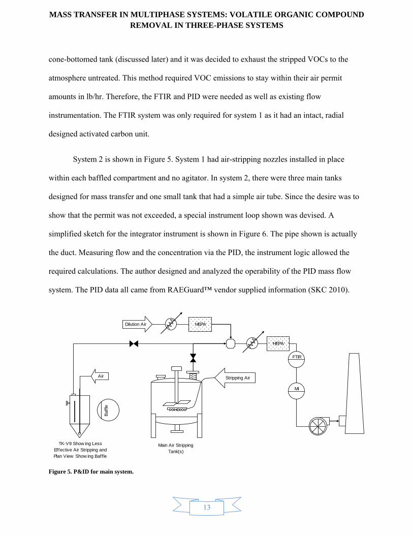
System 2 is shown in Figure 5. System 1 had air-stripping nozzles installed in place
within each baffled compartment and no agitator. In system 2, there were three main tanks
designed for mass transfer and one small tank that had a simple air tube. Since the desire was to
show that the permit was not exceeded, a special instrument loop shown was devised. A
simplified sketch for the integrator instrument is shown in Figure 6. The pipe shown is actually
the duct. Measuring flow and the concentration via the PID, the instrument logic allowed the
required calculations. The author designed and analyzed the operability of the PID mass flow
system. The PID data all came from RAEGuard™ vendor supplied information (SKC 2010).
Figure 5. P&ID for main system.
Stripping Air
HEPA
HEPADilution Air
Main Air Stripping Tank(s)
FTIR
MI
Air
Baf
fle
TK-V9 Show ing Less Effective Air Stripping and Plan View Show ing Baffle

MASS T
Figure 6. Si
A RAEG
to match
feet per m
molecula
VOC=4
Therefor
The rate
TRANSFER
implified VOC
Guard™ PID
the expectat
minute (scfm
ar weight of
3
2lb/hr
00ft /min
e, the scale w
in lb/hr is fo
R IN MULTREMO
mass flow instr
was used to
tion value fo
m) to determi
166 g/mol fo
3r 359ft /lbm
166lb/lbmol
was set at 0-
ound by a mu
IPHASE SYOVAL IN TH
rument.
o analyze and
or meeting th
ine the scale
or PCE, the
mol
60min/hr
-1000 ppmv.
ultiplying op
YSTEMS: VHREE-PHA
14
d indicate to
he 2 lb/hr cri
e for the PID
concentratio
610 =180 pp
perator funct
VOLATILEASE SYSTE
otal VOCs. T
iterion. Assu
D, the total V
on in parts pe
vpm
tion, i.e.:
E ORGANICEMS
The scale for
uming 400 st
VOC assumin
er million (p
C COMPOU
r the PID nee
tandard cubi
ng a conserv
ppmv) is:
UND
eded
ic
ative
(1)

MASS TRANSFER IN MULTIPHASE SYSTEMS: VOLATILE ORGANIC COMPOUND REMOVAL IN THREE-PHASE SYSTEMS
15
v 6 3
-5v
1 60min lbmol 134lblbVOC/hr = ppm scfm 1.27 =
10 hr 359ft lbmol
ppm scfm 2.84x10
(2)
The multiplication operator for the instrument is then 2.84 × 10⁻⁵ ppmv-scfm. The mixture
correction factor (CF) is determined based on the individual correction factors from the vendor at
the PID lamp power used (in this case 10.6 eV) and the mole fractions of the gas-free VOCs (i.e.,
mole fractions based only on VOCs).
1
1n
mixii
i
CFx
CF
(3)
The mixture correction factor (CFmix) is 0.55. It was recommended to leave the humidity
correction factor at 1.0 unless the humidity is consistently higher during operations than about
20% as shown in the humidity correction plot, Figure 7.

MASS TRANSFER IN MULTIPHASE SYSTEMS: VOLATILE ORGANIC COMPOUND REMOVAL IN THREE-PHASE SYSTEMS
16
Figure 7. Humidity correction factor.
The factor of 1.27 shown in Eq. 2 is the fG. The exterior factor (fG) is referred to as an
exterior factor whereas the PID correction factors are entered directly into the PID. The fG is
based on the fact that the PID cannot “see” all of the organics present. More powerful UV model
PIDs can be used but they require daily calibration and frequent bulb changes. That is why this
unit was used with correction factors.
The method to get the factor is based on obtaining the ionization data on all VOCs
expected and comparing lamps to what is effective by each energy lamp. The 10.6 eV UV lamp
does not have enough energy to ionize all VOCs, e.g. TCA as shown in Table 1. Therefore, using
a standard basis of 1 mol/hr total VOC, the mass ratio of the VOCs ionized by the 11.7 lamp to
those ionized by the 10.6 eV-lamp provides the fG as shown. Of course, this is an estimate since
Humidity Correction Factors for MiniRAE 2000
Multiply correction factor by reading to obtain actual concentration
0.0
0.2
0.4
0.6
0.8
1.0
1.2
1.4
1.6
1.8
0 20 40 60 80 100
Percent RH
Co
rrec
tio
n F
acto
r
10C/50F
15C/59F
20C/68F
23C/73F
26.7C/80F
32.2C/90F

MASS TRANSFER IN MULTIPHASE SYSTEMS: VOLATILE ORGANIC COMPOUND REMOVAL IN THREE-PHASE SYSTEMS
17
the ratios of gases change over time. However, the TCA has the largest effect and is close
enough in volatility for the instrument to be viable.
Table 1. Calculation of PID Exterior Factor.

MASS TRANSFER IN MULTIPHASE SYSTEMS: VOLATILE ORGANIC COMPOUND REMOVAL IN THREE-PHASE SYSTEMS
18
Similar analysis was performed for all of the System 2 Tanks. The system 2 Tanks were 20 ft
high tanks had a ring-bubbler agitator system installed in recommended positions (Treybal
1987). Most of the mass transfer occurs in the zone between the impeller and the bubbler system.
This system worked extremely well. However, the data obtained is of little use because of
various activities the author had no control over. However, a method of PID operation was
determined and used based on these methods.
PID by 11.7 eV PID by 10.6 eV
VOC Formula mole/hr ppm mol/hr ppm
Carbon Tetrachloride CCl4 1.25E-03 17 0 0
Chloroform CHCl3 4.21E-02 559 0 0
Dichloromethane CH2Cl2 3.99E-04 5 0 0
Chloromethane CH3Cl 1.91E-02 254 1.91E-02 254
Perchloroethene C2Cl4 9.08E-02 1208 9.08E-02 1208
Trichloroethene C2HCl3 6.68E-01 8884 6.68E-01 8884
cis-1,2-Dichloroethene C2H2Cl2 7.60E-04 10 7.60E-04 10
1,1-Dichloroethene C2H2Cl2 1.48E-02 197 1.48E-02 197
Vinyl Chloride C2H3Cl 1.16E-02 154 1.16E-02 154
1,1,1-Trichloroethane C2H3Cl3 1.30E-01 1725 0 0
1,1-Dichloroethane C2H4Cl2 8.78E-04 12 0 0
1,2-Dichloroethane C2H4Cl2 2.00E-02 265 0 0
Chloroethane C2H5Cl 4.83E-04 6 0 0
Total 1.00E+00 13296 8.05E-01 10707
MWave 131 MWave 134
g/hr by 11.7 eV 7.64E-03 g/hr by 10.6 eV 6.02E-03
Exterior Factor 1.27

MASS T
T
volatile m
liquid sol
mechanic
Figure 8. M
TRANSFER
The system 2
mercury wer
lubility base
cally in Figu
Mechanical Arra
R IN MULTREMO
small tank w
re present. In
ed on equilib
ure 8.
angement of Sm
IPHASE SYOVAL IN TH
was a specia
n fact, the ca
brium calcula
mall, System 2 T
YSTEMS: VHREE-PHA
19
al case where
alculated liqu
ations under
Tank.
VOLATILEASE SYSTE
e very high V
uid VOC con
r most startin
E ORGANICEMS
VOC concen
ncentrations
ng situations
C COMPOU
ntrations and
exceeded th
s. It is shown
UND
d
he
n

MASS TRANSFER IN MULTIPHASE SYSTEMS: VOLATILE ORGANIC COMPOUND REMOVAL IN THREE-PHASE SYSTEMS
20
3.2 Derivation of Three-Phase Mass Transfer
There is a need to derive the appropriate relations from air-stripping a VOC adsorbed
onto a solid into the air via a water medium. This process is quite involved as a result of the solid
phase. The process is shown in Figure 9 and simplified in Figure 10.
Figure 9. Pictorial Illustration of Solid Transfer to Gas Bubbles.
CAB CA
iv
Air bubble
pA, CAv*
pAi
XA, CAs*
XAi, CA
is
Solid particle

MASS T
Figure 10. S
In referen
assumed
iDAX = k
iA A
p = H C
TRANSFER
Solid to Gas Tr
nce to Figure
(Bird 1960)
i1D AC
i2A
C
R IN MULTREMO
ransfer Diagram
e 10, the foll
):
IPHASE SYOVAL IN TH
m.
lowing relat
YSTEMS: VHREE-PHA
21
ions hold. A
VOLATILEASE SYSTE
At the interfa
E ORGANICEMS
aces equilibri
C COMPOU
ium is usual
UND
ly
(4)
(5)

MASS TRANSFER IN MULTIPHASE SYSTEMS: VOLATILE ORGANIC COMPOUND REMOVAL IN THREE-PHASE SYSTEMS
22
The molar rates of mass transfer are the same through each phase. There is significant adsorption
of various material including VOCs and water in and on solids of various particle sizes. This
analysis assumes the solid on the dry basis (units and analogies are presented in Appendix A).
Mass transfere from the solid is:
* 1i iA s A A s D A A
sN k X X k k C C (6)
In the equation above, the mass transfer coefficient, ks, is related to Knudson diffusion:
Ks L
Dk
R (7)
It is assumed for this paper that this coefficient is very large compared to the solid-liquid and liquid mass transfer coefficients and is therefore neglected.
The next mass transfer rate is sometimes referred to the solid-liquid mass transfer
coefficient (Oldshue 1983).
1i BA sL D A AN k k C C (8)
As shown in Figure 10, it is the transfer across the liquid film outside of the solid. It
cannot exceed the solubility in the liquid media. Most workers ignore the transfer relation in
Figure 10. This will be examined later. Like a liquid mass transfer coefficient, the so-called solid-
to-liquid coefficient depends on the process. It is defined by the Sherwood number
(dimensionless groups are discussed in Appendix B) for solids treatment defined as:
2sL s p
iw
k a dSh
D (9)
e Overall mass transfer coefficients can be based on any phase, liquid is used in this analysis

MASS TRANSFER IN MULTIPHASE SYSTEMS: VOLATILE ORGANIC COMPOUND REMOVAL IN THREE-PHASE SYSTEMS
23
And the correlation for this system:
1/2 1/3Sh=2+0.72Re Sc (10)
If the particle size is small enough, this converges to 2 and is easier to work with for this
derivation however, that is not a requirement. Moving to the right of the diagram, the liquid
phase local mass transfer of which impeller power correlations are available and were used
(Perry 1997), (Treybal 1987) to determine the volumetric liquid-phase local coefficient kLa
(Appendix A provides the relationships between the volumetric type-coefficients and regular
coefficients):
0.4
1/20.026 gL s
Pk a v
V
(11)
Where: vs is the superficial stripping gas velocity. Then, the flux from the liquid phase to the gas
bubble is:
2B iA L A AN k C C (12)
Finally, the transfer across the gas phase resistance is provided by:
*2iA G A A
vAN k H C C (13)
The overall transfer coefficient is the same for each phase and is determined by:
1 2 *1* 2i i B B i iAA A A A A A Aa
L
s vAo
NC C C C C C C C
K (14)
Therefore:
MASS TRANSFER IN MULTIPHASE SYSTEMS: VOLATILE ORGANIC COMPOUND REMOVAL IN THREE-PHASE SYSTEMS
24
1 1 1 1 1oaL s D sL D L G AK k k k k k k H (15)
The mass flux of component A is therefore:
* *oaA L A
vA
sN K C C (16)
The above result uses two nonexistent or virtual concentrations. CAs* is the nonexistent liquid
concentration of the solid and CAv* is the nonexistent concentration of the liquid in the gas phase.
The nonexistent variables are common usages in mass transfer and illustrate one of the major
differences with heat transfer. Since the desired results are in terms of bulk solid concentrations
and bulk partial pressures, the above equation becomes:
oa A AA L
D A
X pN K
k H
(17)
If the value of ks is large, true for most VOCs, the first is neglected. However, the kD
could be large, e.g., activated carbon which would have the opposite effect. This is the main risk
and uncertainty that testing would help elucidate. For this project, the kDs’ appeared low enough
that it was more like a porous mineral and could be neglected in the overall mass transfer
coefficient. For low solubility VOCs, the last term is also neglected, i.e., the liquid coefficient is
controlling (Sherwood 1939). The differential equationf based on the nonexistent liquid phase is:
*
* *oas
As vA
L A
dCK a C C
dt (18)
f Note the use of a, the specific area discussed later

MASS TRANSFER IN MULTIPHASE SYSTEMS: VOLATILE ORGANIC COMPOUND REMOVAL IN THREE-PHASE SYSTEMS
25
Multiplying through by kD provides the differential (see Appendix C for relationships of
different forms of the transport PDEs) based on the solid concentration:
oaA D As A
A
dX k pK a X
dt H
(19)
To make Eq. 7 useable, need to solve for the molar rate, hence:
oa D As s A
A
k pt K aM X
H
(20)
Solving using the following two, Eq. 21 and Eq. 23:
( )
A A
A s
p t t
P t
(21)
Assuming:
A s (22)
A A Ap X (23)
Where:
1Λ
1
oas s D
A oass s s D
oas s D AA
K aM k
K aM kPK aM k HP H
(24)
The above values are all known. Therefore, the final result is based on known quantities:
Λ1oaA A
s AA
dXK aX
dt H
(25)
Note that a similar result can be found in a liquid-vapor system containing no solids (high air-
stripping compared to mass transfer rate). This is shown in Eq. 27:

MASS TRANSFER IN MULTIPHASE SYSTEMS: VOLATILE ORGANIC COMPOUND REMOVAL IN THREE-PHASE SYSTEMS
26
1λ
1L L
As sL L
A L L A
k aVk aV
P H Pk aV H
(26)
The solution to Eq. 25 is via separable ordinary differential equation (ODE):
( )1 /oaAs s A A
A
dXK a H dt
X= - Lò ò (27)
The explicit result is:
( )1 /
0
oas s A AK a H t
A AX X e
- - L= (28)
The results are plotted in Figure 11g. Since the goal was to ensure each component was reduced
below 30 mg/kg, the theory predicts this to be easily accomplished as shown (see Appendix D
for the values of the constants used). Also, even though they had restricted operations without
the activated carbon, the system performed admirably and commensurate with the predictions in
Figure 11.
g Some of the constants are from memory since the laboratory retained the initial publications. However, this is a fair representation of the results as initially planned to operate.

MASS TRANSFER IN MULTIPHASE SYSTEMS: VOLATILE ORGANIC COMPOUND REMOVAL IN THREE-PHASE SYSTEMS
27
0
5000
10000
15000
20000
25000
30000
35000
40000
45000
0 10 20 30 40 50
Solid
Concentration, mg/kg
Time, Hours
TCA
TCE
PCE
Figure 11. Theoretical prediction of time to air-strip tanks.
It’s relatively easy to show the relationship among the overall coefficients using the developed
information since the fluxes through all interfaces are the same, e.g.:
oa oa oaD A A A A AS A L G A
A D A D
k p X p X HK X K K p
H k H k
(29)
Hence:
oaoa LS
D
KK
k (30)
Similarly;
oaoa LG
A
KK
H (31)

MASS TRANSFER IN MULTIPHASE SYSTEMS: VOLATILE ORGANIC COMPOUND REMOVAL IN THREE-PHASE SYSTEMS
28
oa oaAS G
D
HK K
k (32)
If KS is plotted versus KG, the slope is HA/kD. This slope is the ratio of the liquid-gas
equilibrium coefficient (Henry’s Law constant) to the solid-liquid partition coefficient. While the
mass transfer processes are important, this ratio is a good predictor of the volatility from a
volatile liquid within a solid suspended in a liquid. PCBs are troublesome in rivers and streams
for this reason, e.g., PCBs have a high kD and low HA and can usually be ignored in air stripping
but would need treatment via a different process in sludge’s, rivers, stream, and similar
processes, e.g., high energy chemistry.
Rebound occurs in solid-liquid and three-phase systemsh. Rebound is a repartitioning of
VOCs after an initial apparent removal. Rebound can be predicted in certain systems such as
being dealt with here. The time to equilibrium is not known, but for contained, relatively small
solids this is expected to be eight hours or possibly less. In any case, the procedure used was as
follows:
The transients based on mass transfer were incrementally plotted using XL™ spreadsheet by the
following procedure:
1 Calculate the X and Y vs. t (e.g., from the above relations).
2 Calculate the mass transfer rate.
3 Calculate the remaining mass.
h The rebound effects were only used in the second system designed.

MASS TRANSFER IN MULTIPHASE SYSTEMS: VOLATILE ORGANIC COMPOUND REMOVAL IN THREE-PHASE SYSTEMS
29
4 Based on remaining mass, calculate equilibrium. If a liquid phase VOC concentration
exceeds solubility, use the solubility concentration.
5 The stripping must be stopped after awhile due to low driving forces and the VOC
concentrations are allowed to equilibrate.
6 Stripping rates, i.e., air flow rates, are increased.
7 The next days starting concentration is the last days equilibrium value.
8 The method to determine equilibrium using the three phases is:
A A s A L A GM X M C V Y V= + + (33)
9 By use of the following equilibrium relations:
AA DA A A A A A
pX k C p H C Y
RT= = = (34)
10 Combining Eq. 22 and 23:
AA
L G As
DA DA
MX
V V HM
k k RT
=
+ +
(35)
11 The other phases can be calculated using the relations in Eq. 23., i.e.,
AA
G ADA s L
MC
V Hk M V
RT
(36)

MASS TRANSFER IN MULTIPHASE SYSTEMS: VOLATILE ORGANIC COMPOUND REMOVAL IN THREE-PHASE SYSTEMS
30
A AA
G ADA s L
H Mp
V Hk M V
RT
(37)
4.0 Results
4.1 Results from Laboratory Data
The data from the system that had testing suggest that the mass transfer coefficient is a
function of time raised to some power (e.g., k α tn). The value of n was taken to be –½ , based on
the limited theoretical justification (penetration theory) presented by previous mass transfer
analysisi, (Bird 1960), (Treybal 1987), (Thibodeaux 1979). The results of the data from the wet
test, along with model results are shown in Figure 4. The model uses the conservative method of
first and last points as shown to try and capture rebound effectsj and k α t-1/2.
i This does not imply a match with theory only analogy as the theoretical analysis was for local time only. j Rebound occurs chiefly in solid phase mass transfer. During mass transfer, the measured concentrations in the liquid and/or gas phases are less than the equilibrium values. When mass transfer ceases, the measured concentrations increase to the equilibrium value. The effect can mislead operating personnel that may believe the process is complete when in fact, it is not. It is best to turn the process on and off and measure and plot both gas-phase equilibrium and dynamic concentrations to predict process completion.
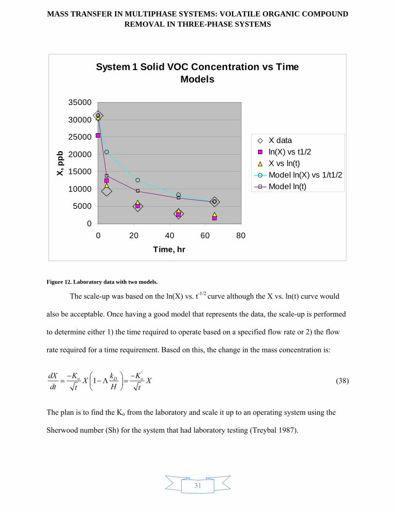
MASS TRANSFER IN MULTIPHASE SYSTEMS: VOLATILE ORGANIC COMPOUND REMOVAL IN THREE-PHASE SYSTEMS
31
Figure 12. Laboratory data with two models.
The scale-up was based on the ln(X) vs. t-1/2 curve although the X vs. ln(t) curve would
also be acceptable. Once having a good model that represents the data, the scale-up is performed
to determine either 1) the time required to operate based on a specified flow rate or 2) the flow
rate required for a time requirement. Based on this, the change in the mass concentration is:
'
1o oDK KkdXX X
dt Ht t
(38)
The plan is to find the Ko from the laboratory and scale it up to an operating system using the
Sherwood number (Sh) for the system that had laboratory testing (Treybal 1987).
System 1 Solid VOC Concentration vs Time Models
0
5000
10000
15000
20000
25000
30000
35000
0 20 40 60 80
Time, hr
X, p
pb
X data
ln(X) vs t1/2
X vs ln(t)
Model ln(X) vs 1/t1/2
Model ln(t)

MASS TRANSFER IN MULTIPHASE SYSTEMS: VOLATILE ORGANIC COMPOUND REMOVAL IN THREE-PHASE SYSTEMS
32
Ref
c dL B BL G L h
L L
K d d gSh a b Sc
cD D
(39)
The parameters above are used from those recommended for the type of system. Some of them
will change regimes depending on the Reynolds number (Rek). Also, the “a” shown in Eq. 40 is
neglected since Eq. 40 is used as a ratio. This has little effect since the right side in this system is
much greater than a. There was extensive numerical work in doing this and therefore not
included here but is available in the literature on the www. However, the fact remains that the
laboratory data was scaled up and compared with actual data and indicate a fairly good fit. The
differences would be the fact that rebound was not accounted for and the large difference in
geometry between laboratory and scale-up systems. It was believed at the time rebound would
not have a large impact based on the small amounts of PCE present. However, some minor
rebound is believed to have occurred.
k There are several forms of the Reynolds number that were used.

MASS TRANSFER IN MULTIPHASE SYSTEMS: VOLATILE ORGANIC COMPOUND REMOVAL IN THREE-PHASE SYSTEMS
33
Figure 13. Scale-up versus Actual Data.
Based on this actual data, there was not severe rebounding. However, observation of all of the
data show rebound signatures and the over-design was justified. This was a difficult tank to
scale-up. Even with the scale-up, the data results are comparable to the laboratory scale-up
predictions. The procedure, once provided the operating air flow rate, is to:
1 Determine the average velocity (which involved determining the average width based on the
mass in the tank and geometry):
Comparison of Scaleup with Operations Results
0.1
1
10
100
1000
0.0 10.0 20.0 30.0 40.0 50.0
Time, hr
Y, p
pm
v
y, ppmv
Data

MASS TRANSFER IN MULTIPHASE SYSTEMS: VOLATILE ORGANIC COMPOUND REMOVAL IN THREE-PHASE SYSTEMS
34
2 Determine the slip velocityl based on approximate curve fit from (Treybal 1987).
3 Determine the gas holdup.
4 Determine the orifice Reynolds number.
5 Determine the bubble diameter based on Reo.
6 Determine gas Re based on slip velocity, bubble diameter, and liquid properties.
7 Ignoring the “a” in Eq. 28, the Sherwood number ratios were used to get the scaled up mass
transfer coefficient:
1
2 22 1
1 1
Re
Re
c j
G BL L
G B
dK K
d
(40)
8 Determine the bubble specific surface area:
6B
B
ad
(41)
9 Eq. 29 and 30 are combined to provide K’o in Eq. 27.
4.2 Design Based On Theory Alone
The theory developed in Section 3 was used for the operations used in several
configurations including demonstrating the Volatility in the cone bottomed tank (TK-V9) shown
in Figure 8. Similar analysis was performed for all of the V-Tanks. The V-Tanks were 20 ft high
tanks had a ring-bubbler agitator system installed in recommended positions (Treybal 1987).
l This is difficult to envision when it’s not counter-current flow.

MASS TRANSFER IN MULTIPHASE SYSTEMS: VOLATILE ORGANIC COMPOUND REMOVAL IN THREE-PHASE SYSTEMS
35
Most of the mass transfer occurs in the zone between the impeller and the bubbler system. This
system worked extremely well for the main tanks and met all of the environmental requirements
after air-stripping for approximately a week. Based on theory, it would require 42 hours
neglecting slight rebound effects for dilute, small particle systems.
However, similar efforts used on TK-V9 were not successful since the sludge’s were
more concentrated in VOCs than previously believed. In addition the sludge’s formed
agglomeration and packed solids especially behind the baffle. The effect of this was to change
mechanisms to packed solid diffusion. The data collected for TK-V9 were from later efforts after
some of the material was removed via other methods.
The theoretical models for system 2 discussed previously were used to construct Figure
14 for one potentially effective scenario to obtain an approximate timeframe. The stripping air
was gradually bumped up. It operated only during daytime operation which was also requested.
As shown in Figure 14, the calculated equilibrium value used as the initial concentration
gradually decreased whereas the gas concentrations calculated via mass transfer decreased
relatively rapidly. One of the main needs for concentrated sludge’s with low water content
require pulsed operations, i.e., on-off operation. The parameters needed to predict this can be
measured in non-radioactive cases. The Henry’s law constants are likely close to literature and
recommended values for pure water. The solid-liquid partition coefficient could vary
significantly than the assumed soil values. However, sensitivity studies indicated this to not be a
major effect.
The mass transfer coefficients (kS and kL) are less for this case than for the sparge ring
and mixer design of the main tanks. This means it takes longer than the main tanks. It is believed
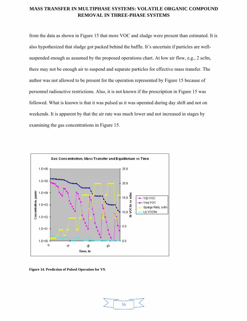
MASS T
from the
also hypo
suspende
there may
author w
personne
followed
weekend
examinin
Figure 14. P
TRANSFER
data as show
othesized tha
ed enough as
y not be eno
as not allow
el radioactive
d. What is kn
ds. It is appar
ng the gas co
Prediction of Pu
R IN MULTREMO
wn in Figure
at sludge got
s assumed by
ough air to su
wed to be pre
e restrictions
nown is that i
rent by that t
oncentrations
ulsed Operation
IPHASE SYOVAL IN TH
e 15 that mor
t packed beh
y the propos
uspend and s
sent for the o
s. Also, it is
it was pulsed
the air rate w
s in Figure 1
n for V9.
YSTEMS: VHREE-PHA
36
re VOC and
hind the baff
ed operation
separate part
operation rep
not known i
d as it was o
was much low
15.
VOLATILEASE SYSTE
sludge were
fle. It’s unce
ns chart. At l
ticles for eff
presented by
if the prescri
operated duri
wer and not
E ORGANICEMS
e present tha
rtain if parti
low air flow
fective mass
y Figure 15 b
iption in Fig
ing day shift
increased in
C COMPOU
an estimated.
icles are wel
, e.g., 2 scfm
transfer. Th
because of
gure 15 was
t and not on
n stages by
UND
. It is
l-
m,
he
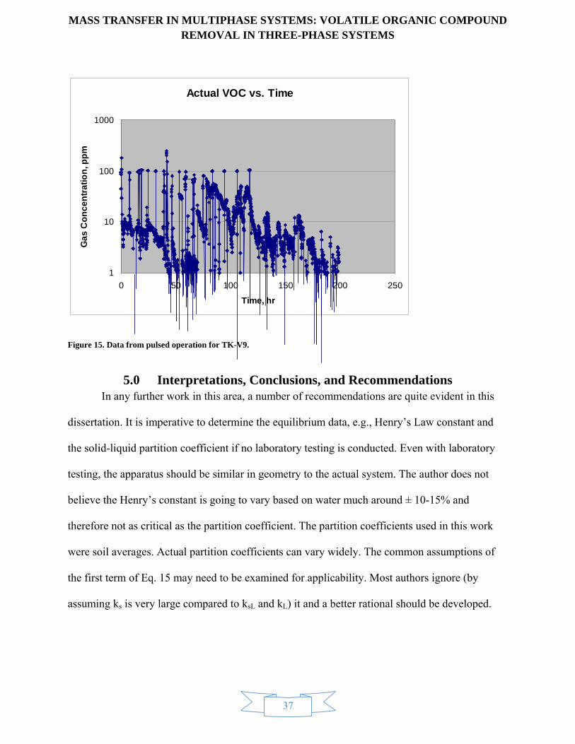
MASS TRANSFER IN MULTIPHASE SYSTEMS: VOLATILE ORGANIC COMPOUND REMOVAL IN THREE-PHASE SYSTEMS
37
Figure 15. Data from pulsed operation for TK-V9.
5.0 Interpretations, Conclusions, and Recommendations In any further work in this area, a number of recommendations are quite evident in this
dissertation. It is imperative to determine the equilibrium data, e.g., Henry’s Law constant and
the solid-liquid partition coefficient if no laboratory testing is conducted. Even with laboratory
testing, the apparatus should be similar in geometry to the actual system. The author does not
believe the Henry’s constant is going to vary based on water much around ± 10-15% and
therefore not as critical as the partition coefficient. The partition coefficients used in this work
were soil averages. Actual partition coefficients can vary widely. The common assumptions of
the first term of Eq. 15 may need to be examined for applicability. Most authors ignore (by
assuming ks is very large compared to ksL and kL) it and a better rational should be developed.
Actual VOC vs. Time
1
10
100
1000
0 50 100 150 200 250
Time, hr
Ga
s C
on
ce
ntr
ati
on
, pp
m

MASS TRANSFER IN MULTIPHASE SYSTEMS: VOLATILE ORGANIC COMPOUND REMOVAL IN THREE-PHASE SYSTEMS
38
With the Henry’s Law constants and partition coefficients available, some interesting
predictions can be made, e.g., if the ratio HA/kD is large, meaning a volatile compound with small
affinity towards the solid, good separation is predicted and the converse is also true. The semi-
volatiles like PCBs are poor candidates for the stripping process based on their large partition
coefficients and small Henry’s Law constants. Examining Eq. 43 it is seen that the so-called
stripping factor is similar to resistances, a mass transfer and an equilibrium resistance. It is
interesting to note that the partition coefficient is a factor of the mass transfer resistance.
1Λ
1As
oas s D APK aM k H
(42)
Of course, with no stripping air, the chief assumption is no longer valid and there is no net mass
transfer since:
iA AX X (43)
In addition the ratio of the two stripping factors is instructive. The relation in Eq. 44 converges
to 1.0 as the particle size approaches zero and/or for very small kD’s.
0lim 1
pD
(44)
Therefore the methods within this paper are useful in assessing stripping viability in
solid-liquid-gas systems. The ratio shown in Eq. 44 could be used to estimate the time required
for a solids containing system compared to a known liquid system for example.

MASS TRANSFER IN MULTIPHASE SYSTEMS: VOLATILE ORGANIC COMPOUND REMOVAL IN THREE-PHASE SYSTEMS
39
References Anderson, J.D. Computational Fluid Dynamics. McGraw-Hill, 1995.
Ashworth, S.C. Lopez, D.A. Design for VOC Control for the TSF-09/18 V-Tank Remedial Action, EDF-4956 Rev. 1. EDF, Idaho Falls,ID: Idaho National Laboratory, 2004.
Bird, R.B., Stewart, W.E., Lightfoot, E.N. Transport Phenomena. John Wiley & Sons, 1960.
Braida, W., Ong, S.K. "Influence of Porous Media and Airflow Rate on the Fate of NAPLs Under Air Sparging." Transport in Porous Media 38, 2000: 29-42.
Chrysikopoulos, C.V., Hsuan, P., Fyrillas, M.M., Lee, K.Y. "Mass Transfer Coefficient and Concentration Boundary Layer Thickness for a Dissolving NAPL Pool in Porous Media." Journal of Hazardous Materials B97, 2003: 245-255.
Chrysikopoulos, C.V., Kim, T.J. "Local Mass Transfer Correlations for Nonaqueous." Transport in Porous Media 38, 2000: 167-187.
EPA, U.S. "APPENDIX K, Soil Organic Carbon (Koc) / Water (Kow) Partition." http://www.epa.gov/superfund/health/conmedia/soil/pdfs/appd_k.pdf.
Fishwick, R. P., Winterbottom, J. M., Stitt, E. H. "Effect of Gassing Rate on Solid–Liquid Mass Transfer Coefficients and Particle Slip Velocities in Stirred Tank Reactors." Chemical Engineering Science 58, 2003: 1087-1093.
Harnby, N., Edwards, M.F., Nienow, A.W. Mixing in the Process Industries, 2nd ed. Butterworth-Heinemann, 1992.
Hemond, H.F., Fechner, E. J. Chemical Fate and Transport in the Environment. Academic Press, 1994.
Höcker, H., G. Langer, U. Werner. "Mass Transfer in Aerated Newtonion and Non-Newtonion Liquids in Stirred Reactors." Ger. Chem. Eng. 4, 1981: 51-62.
Idaho National Laboratory. Air Stripping Radioactive Solids. Internal, confidential, Idaho Falls: INL, 2005.
Levenspiel, O. Chemical Reaction Engineering, 2nd ed. Wiley, 1972.
Montgomery, J.H., Welkom, L.M. Groundwater Chemicals Desk Reference. Chelsea Michigan: Lewis Publishers, Inc., 1991.
Muroyama, K., Nakade, T., Goto, Y., Kato, T. "Wall-to-Liquid Mass Transfer in a Gas–Slurry Transport Bed." Chemical Engineering Science 56, 2001: 6099–6106.
Oldshue, J.Y. Fluid Mixing Technology, Chemical Engineering. McGraw-Hil, 1983.
Perry, R.H., Green, D.W. Perry’s Chemical Engineers’ Handbook, 7th ed. McGraw-Hill, 1997.

MASS TRANSFER IN MULTIPHASE SYSTEMS: VOLATILE ORGANIC COMPOUND REMOVAL IN THREE-PHASE SYSTEMS
40
Poe, S.H., Valsaraj, K.T., Thibodeaux L.J. and Springer, C. "Equilibrium Vapor Phase Adsorption of Volatile Organic Chemicals on Dry Soils." Journal of Hazardous Materials, 19, 1988: 17-32.
RCRA. 42 USC 6901 et seq. (United States Congress, 1976).
Sander, Rolf. "Compilation of Henry’s Law Constants for Inorganic and." http://www.mpch-mainz.mpg.de/~sander/res/henry.html. April 8, 1999.
Sherwood, T.K. "AIChE Meeting." 1939.
SKC. MiniRAE 2000. January 25, 2010. http://www.skcinc.com/prod/730-0201-000.asp (accessed 2007).
Thibodeaux, L.J. Chemodynamics, Environmental Movement of Chemicals in Air, Water, and Soil. John Wiley and Sons, 1979.
Treybal, R.E. Mass-Transfer Operations. McGraw-Hill Classic Reissue, 3rd ed., 1987.
U.S. "42 USC 6901 et seq." Resource Conservation Recovery Act. United States Library of Congress, 1976.
Valentin, F.H.H. "Mass Transfer in Agitated Tanks." Progress Review, Vol. 12, No. 8, 1967.
Valsaraj, K.T. Elements of environmental engineering: thermodynamics and kinetics. CRC Press, Inc., 1995.
Van’t Riet, K. "Review of Measuring Methods and Results in Non-Viscous Gas-Liquid Mass Transfer in Stirred Vessels." Ind. Eng. Chem. Des. Dev., Vol. 18, No. 3, 1979.
Yagi, H., Yoshida, F. "Gas Adsorption by Newtonion and Non-Newtonion Fluids in Sparged Agitated Vessels." Ind. Eng. Chem. Des. Dev., Vol. 14, No. 4, 1975.
Zhao, B., Wang, J., Yang, W., Jin, Y. "Gas–Liquid Mass Transfer in Slurry Bubble Systems, I. Mathematical Modeling Based on a Single Bubble Mechanism." Chemical Engineering Journal 96, 2003: 23-27.
Zlokarnik, M. "Sorption Characteristics for Gas-Liquid Contacting in Mixing Vessels." Advances in Biochemical Engineering, Vol. 8, Springer-Verlag, 1978.

MASS TRANSFER IN MULTIPHASE SYSTEMS: VOLATILE ORGANIC COMPOUND REMOVAL IN THREE-PHASE SYSTEMS
41
Appendix A, Units and Transport Analogies

MASS TRANSFER IN MULTIPHASE SYSTEMS: VOLATILE ORGANIC COMPOUND REMOVAL IN THREE-PHASE SYSTEMS
42
Mass transfer is unique in terms of units. It is similar to heat transfer except that when there is inter-phase mass transfer, different bulk quantities are used. The transport of mass, heat, and momentum are analogous. After applying the usual assumptions (Bird 1960) for illustration of this and applying to a single dimension for the partial differential equations (PDE) of motion, energy, and mass:
2
2x x
y
v vv
y y
(45)
2
2y
T Tv
y y
(46)
2
2A A
y AB
C Cv D
y y
(47)
It is immediately obvious that analogies are relevant. In fact, many correlations use analogies to determine properties from one system and apply to the other in similar systems say knowledge of heat transfer applied to mass transfer. The constants that are needed are also analogous in that they reflect the diffusion magnitude of momentum, heat, and mass:
ν = µ/ρ Known as the kinematic viscosity (dynamic viscosity/density) and is the resistance of a fluid sliding between two surfaces. It can be envisioned as momentum diffusivity. The usual units are the same for all of these diffusivity constants, cm2/s.
α = k/ρcp Known as the thermal diffusivity. It is the ratio of thermal conductivity of a material to density and heat capacity.
DAB This is the mass diffusivity between two components A and B as in two different gases or, as in this papers case, a volatile solute into a liquid.
The units of mass transfer can vary widely from the units of heat transfer even though the analogies still hold true. While temperature is the chief dependent variable in heat transfer, mass transfer units can be liquid concentrations, gas concentration, partial gas pressures, mole fractions, solid concentrations, and other less well known. This is evident in the mathematical manipulations used within, e.g., the solid mass transfer flux is:
iA s A AN k X X (48)
For the flux to have the correct units of moles or mass per time per unit area,

MASS TRANSFER IN MULTIPHASE SYSTEMS: VOLATILE ORGANIC COMPOUND REMOVAL IN THREE-PHASE SYSTEMS
43
2s
Mk
L t (49)
Similarly for the liquid and gas:
i iA L A A G A AN k C C k p p (50)
L
Lk
t (51)
2G
mk
atmL t (52)
Further complicating mass transfer calculations is the convention to use coefficients in terms of inverse time, 1/t for use in mass transfer rates as opposed to fluxes. Much of the liquid-phase mass transfer literature has many correlations for this conversion. The idea is to apply an area of mass transfer such that:
iA L A Ak A C C (53)
In moles or mass per time. However, in use of the partial differential equations rates are similar and commensurate with chemical kinetics, i.e., rate in moles or mass per unit volume per time. Therefore, the standard usage is to find the area per unit volume or mass, a = A/V (L2/L3). The single-phase coefficients then become:
2
2* 1/s
M Lk a t
L t M (54)
2
3* 1/L
L Lk a t
t L (55)
2
2 3* * 1/G
m Lk a RT t
atmL t L (56)
The same were applied to the overall coefficients. However some manipulation has to occur in order to ensure equivalent areas or area averages are being accounted for in different phases, e.g.,
1 11 1 1 1oa
L ave
D s s D sL s L G A
K ak k a k k a k a k aH
(57)

MASS TRANSFER IN MULTIPHASE SYSTEMS: VOLATILE ORGANIC COMPOUND REMOVAL IN THREE-PHASE SYSTEMS
44
Where the as is the solids area, L2/Ms and the “a” is the air bubble area, L2/L3.

MASS TRANSFER IN MULTIPHASE SYSTEMS: VOLATILE ORGANIC COMPOUND REMOVAL IN THREE-PHASE SYSTEMS
45
Appendix B, Dimensionless Groups
Dimensionless groups were used extensively herein. The dimensionless groups are used in science and engineering for correlations, comparisons, and determining transport coefficients based on system physics. It is useful to think of dimensionless groups as ratios of forces or similar effects (Placeholder1). A few examples illustrate this:
Reynolds number (Re):
2
2
/
/
v D inertial forcesRe
v D viscous forces
(58)
2 /
v D inertial forcesFr
g gravity forces
(59)
The author’s experience is based on deriving the dimensionless groups by non-dimensionalizing the equations of motion, energy, and mass. For heat transfer within a single phase:
2i
Tq k h T T
z
(60)
To non-dimensionalize, substitute:
2
2
ΘT T
T T
(61)
z
L (62)
Θ/ Θik L h
(63)
Isolating the dimensionless ordinary differential equation reveals the Nusselt number a ratio of heat transferred by convection to that transferred by conduction:
ih LNu
k (64)
Similarly for mass transferm:
m Assumes non-diffusing component B. Both these situations are highly simplified with many assumptions but demonstrate the ideas.

MASS TRANSFER IN MULTIPHASE SYSTEMS: VOLATILE ORGANIC COMPOUND REMOVAL IN THREE-PHASE SYSTEMS
46
2A
A AB i A
CN D k C C
z
(65)
To non-dimensionalize, substitute:
2
2
Γ AC C
C C
(66)
z
L (67)
Γ/ ΓAB iD L k
(68)
Isolating the dimensionless ordinary differential equation reveals the Nusselt number of mass transfer or otherwise known as the Sherwood number, a ratio of convective type mass transfer to diffusion:
i
AB
k LSh
D (69)
Table 2. Often-used dimensionless numbers in mechanical and chemical engineering.
Fo Fourier modulus
Dimensionless time characterizing heat flux into a body
�t/��cpd2
Fr Frouden number Ratio of inertia and gravity forces v2/gd
jH Colburn j factor Dimensionless heat transfer coefficient NuRe-1Pr-0.33
jM Colburn j factor Dimensionless mass transfer coefficient ShRe-1Sc-0.33
Nu Nusselto,p number
Ratio of total and molecular heat transfer hd/
Pe Pécletq number Ratio of advection (convection) to molecular or thermal diffusion
ReLSc (ReLPr)
n William Froude was an English engineer, hydrodynamicist and naval architect. He was the first to formulate reliable laws for the resistance that water offers to ships (such as the hull speed equation) and for predicting their stability. o Ernst Kraft Wilhelm Nußelt was a German physicist. Nußelt studied mechanical engineering at the Munich Technical University (Technische Universität München), where he got his doctorate in 1907. He taught in Dresden from 1913 to 1917. p This has the same form as the Biot number. However, the Biot number is a ratio of external resistance to internal resistance of a solid body q It is named after the French physicist Jean Claude Eugène Péclet.

MASS TRANSFER IN MULTIPHASE SYSTEMS: VOLATILE ORGANIC COMPOUND REMOVAL IN THREE-PHASE SYSTEMS
47
Pr Prandtlr number Ratio of molecular and momentum heat transfer
µcp/
Re Reynoldss number
Ratio of inertia and viscous forces ρdv/µ
Sc Schmidtt
number Ratio of molecular and momentum mass transfer
µ/ρDAB
Sh Sherwoodu number
Ratio of total and molecular mass transfer
kd/DABv
Some of the more difficult elucidation of dimensionless numbers stems from non-dimensionalizing of the governing partial differential equations. The following is one of the more illustrative in fluid mechanics using the references nomenclature (Bird 1960):
* * *02
, ,p pv tv
v p tv v D
(70)
* * *, ,x y z
x y zD D D
(71)
D (usually diameter), v (usually average velocity), and p0 is a convenient reference pressure (e.g., standard pressure = 1 atmosphere).
*1 2 3* * *
Dx y z
(72)
*2 2 2*2 * 2 *3
Dx y z
(73)
r Ludwig Prandtl was a German scientist. He was a pioneer in the development of rigorous systematic mathematical analyses which he used to underlay the science of aerodynamics, which have come to form the basis of the applied science of aeronautical engineering. s Osborne Reynolds was a prominent innovator in the understanding of fluid dynamics. Separately, his studies of heat transfer between solids and fluids brought improvements in boiler and condenser design. t Ernst Schmidt was a German scientist and pioneer in the field of Engineering Thermodynamics, especially in Heat and Mass Transfer. u Thomas Kilgore Sherwood was a noted American chemical engineer and a founding member of the National Academy of Engineering. v Diffusivity based on binary A and B components

MASS TRANSFER IN MULTIPHASE SYSTEMS: VOLATILE ORGANIC COMPOUND REMOVAL IN THREE-PHASE SYSTEMS
48
This is because unit vector dot products: 1 0i i i jand . Using the equations of continuity and
equation of motion:
0v (74)
2Dvp v g
Dt (75)
With some rearranging, the following is arrived at:
** * *2 *
* 2
Dv gDp v
Dt Dv v g
g (76)
The terms in brackets are reciprocals of the Reynolds (Re) number and Froude (Fr) number respectively. If in two different systems the scale factors are such that the Re and the Fr are the same, then both systems are described by identical dimensionless differential equations (Placeholder1). In addition, if the initial and boundary conditions are the same, they are mathematically identical. Such systems are geometrically and dynamically similar and scale-up is easily done in that case.
Another method used to elucidate dimensionless numbers. This is the Buckingham Pi method of dimensional similarity. In the case of local liquid mass transfer as a function of its variables rose to different powers:
1L ABk K v D d (77)
Now by inserting the appropriate dimensions within this assumed equation:
2
1 3
L L M M LK L
t t L Lt t
(78)
There are three equations in L, M, and t respectively:
1 3 2 (79)
0 (80)
1 (81)
Eliminating some of the constant exponents and inserting back into the original equation for local mass transfer:

MASS TRANSFER IN MULTIPHASE SYSTEMS: VOLATILE ORGANIC COMPOUND REMOVAL IN THREE-PHASE SYSTEMS
49
1L
AB
k dK Re Sc
D (82)
Therefore, similar to other dimensionless numbers, the Sherwood number can be found by plotting the Re
Sc to appropriate powers allowing the determination of the local mass transfer coefficients.

MASS TRANSFER IN MULTIPHASE SYSTEMS: VOLATILE ORGANIC COMPOUND REMOVAL IN THREE-PHASE SYSTEMS
50
Appendix C, All Forms of Transport Equations are One

MASS TRANSFER IN MULTIPHASE SYSTEMS: VOLATILE ORGANIC COMPOUND REMOVAL IN THREE-PHASE SYSTEMS
51
This appendix shows how the transport equations (conservation of mass used for illustration) are the same regardless of the observer. The basic development (Bird 1960) is that there are three types of concentration derivatives:
As a fixed observer of flow quantifying the concentration of some quantity of mass in a stream.
For this, it is simply C/t, the partial of C with respect to t holding x, y, and z constant.
As a random moving observer in the stream, the derivatives must include the motion:
dC C C dx C dy C dz
dt t x dt y dt z dt
¶ ¶ ¶ ¶= + + +
¶ ¶ ¶ ¶ (83)
As an observer flowing with the stream, the substantial derivative is as follows:
x y z
DC C C C Cv v v
Dt t x y z
¶ ¶ ¶ ¶= + + +
¶ ¶ ¶ ¶ (84)
The substantial derivative for a moving body with the flow is explained in reference to the relations for a fixed position in the following. Extensive development and analysis is used from the masterful work by Anderson in computational fluid dynamics (CFD). Similar analysis below and many other mathematical tools are available in (Anderson 1995).
Conservation of mass
For a fluid particle moving between 2 points, a Taylor series provides
2 1 2 1( ) ............x xx t
(85)
Dividing by (t2-t1)
lim 2 12 1
2 1
......D
t t vt t x t Dt
(86)
The substantial derivative is shown below in operator form:
Dv
Dt t
(87)
( , , , )f f x y z t (88)
Any function f can be shown using calculus of several variables, e.g.,
df f f dx f dy f dz
dt t x dt y dt z dt
(89)

MASS TRANSFER IN MULTIPHASE SYSTEMS: VOLATILE ORGANIC COMPOUND REMOVAL IN THREE-PHASE SYSTEMS
52
Divergence
V v t n dS v t dS
(90)
dV v tdS
(91)
DVvdV
Dt
(92)
Shrinking the control volume down to δV:
V
D Vvd V
Dt
(93)
Assume δV is small enough that so that the divergence doesn’t change (i.e., it becomes a constant if δV is small enough and therefore comes outside the integral):
D Vv V
Dt
(94)
The divergence is the volume rate of change per unit volume of a moving fluid element, i.e.:
1 D Vv
V Dt
(95)
Case I, Control Volume Fixed
The net amount leaving the volume element = the rate of mass decrease
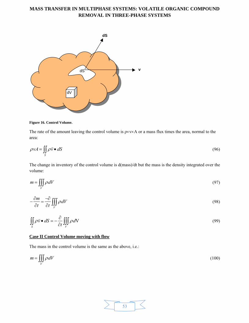
MASS TRANSFER IN MULTIPHASE SYSTEMS: VOLATILE ORGANIC COMPOUND REMOVAL IN THREE-PHASE SYSTEMS
53
Figure 16. Control Volume.
The rate of the amount leaving the control volume is ρvA or a mass flux times the area, normal to the area:
S
vA v dS
(96)
The change in inventory of the control volume is d(mass)/dt but the mass is the density integrated over the volume:
V
m dV (97)
V
mdV
t t
(98)
VS V
v dS dt
(99)
Case II Control Volume moving with flow
The mass in the control volume is the same as the above, i.e.:
V
m dV (100)
dS
dS v
dV

MASS TRANSFER IN MULTIPHASE SYSTEMS: VOLATILE ORGANIC COMPOUND REMOVAL IN THREE-PHASE SYSTEMS
54
Since the mass stays the same while the volume changes or could change, all of the derivatives of the mass are zerow:
0V
Dm DdV
Dt Dt (101)
Case III Fixed Infinitesimally Small Element
Figure 17. Infinitesimally small unit cube.
From the left face and using u as the x velocity, the mass balance is:
( )u
u dx dydz u dydz net decreasex
(102)
This is true because:
fdf dx
x
(103)
These are similar for y and z directions
The time rate of mass increase is (dV =dxdydz)
w It is customary to state that this only applies for stable, non-radioactive elements.
x
y
z
dydzu
i
j
k
dxdyw
dxdzv
dydzdxx
uu
dxdydzz
ww
dxdzdyy
vv

MASS TRANSFER IN MULTIPHASE SYSTEMS: VOLATILE ORGANIC COMPOUND REMOVAL IN THREE-PHASE SYSTEMS
55
/m t dxdydzt
(104)
u v wdxdydz dxdydz
x y z t
(105)
or
0vt
(106)
Case IV, Infinitesimally small element moving with the flow
m V (107)
Since the derivative of the mass is zero everywhere (no change in mass):
D m D V
Dt Dt
(108)
By the multiplication rule of calculus:
0D V D
VDt Dt
(109)
The divergence of the velocity vector is the volume rate of change per unit volume:
1 D Vv
V Dt
(110)
0D
vDt
(111)
Show that case III is the same as case I (Path C in Figure 18)
VS V
v dS dt
(112)
Using the divergence theorem on the left side

MASS T
S
v d
V t
Since the
t
This matc
Figure 18. A
Using Pat
v
Since:
D
Dt t
Now usin
TRANSFER
V
dS
v dV
volume integ
0v dV
ches case III
All Equations a
th B in Figure
v v
vt
ng Path D in F
R IN MULTREMO
v dV
0V
gral is zero, th
0
are Equivalent.
e 18:
v
Figure 18:
IPHASE SYOVAL IN TH
dVt
he inside is ze
YSTEMS: VHREE-PHA
56
ero
VOLATILEASE SYSTE
E ORGANICEMS
C COMPOUUND
(113)
(114)
(115)
(116)
(117)

MASS TRANSFER IN MULTIPHASE SYSTEMS: VOLATILE ORGANIC COMPOUND REMOVAL IN THREE-PHASE SYSTEMS
57
1 ( )0
V V
D D dV DdV dV
Dt dV Dt Dt
(118)
Since this is zero, the integrand is zero because 1 ( )D dV
dV Dt is the divergence, this is the same in the
lower differential box.

MASS TRANSFER IN MULTIPHASE SYSTEMS: VOLATILE ORGANIC COMPOUND REMOVAL IN THREE-PHASE SYSTEMS
58
Appendix D, Materials Properties

MASS TRANSFER IN MULTIPHASE SYSTEMS: VOLATILE ORGANIC COMPOUND REMOVAL IN THREE-PHASE SYSTEMS
59
To enable the analyses that were performed, certain properties were needed. The Henry’s Law constants were determined from a source of tabulated data (Sander 1999). The H for bis(2-ethylhexyl) phthalate was estimated from a different phthalate in the tables. The organic-carbon partition coefficient (Koc) can be calculated from the octanol-water partition coefficient (Kow) discussed in several references, e.g., (Hemond 1994). However, measured values of the Koc’s except PCB were found in an EPA document (EPA n.d.). The Koc for arochlor 1254 was found elsewhere (Montgomery 1991). The Koc’s are placed next to the Henry’s Law constants in Table 3. The actual partition coefficient depends on the amount of organic carbon associated with the solids. In the case analyzed, it was on the order of 105 ppm or foc = 0.1. Then, kD is calculated by:
D oc ock f K
The kD values are placed in the table. By dividing H by kD, the last column shows a qualitative assessment of the likelihood of being removed by air stripping. As expected, the volatile solvents are predicted to be easily removed whereas the higher molecular weight, less-volatile compounds have little removal.
Table 3. Properties of main compounds evaluated.
Chemical Formula H, L-atm/mol Koc, L/kg kD, L/kg H/kD, kg-atm/kgmol
1,1,1-TCA CH3CCl3 16.95 135.00 13.5 1255.49
TCE C2HCl3 10 94.3 9.43 1060.45
PCE C2Cl4 16.95 265 26.5 639.59
PCB Arochlor 1254 0.33 407400 40740 0.01
Bis(2-ethylhexyl) phthalate C6H4(CO2C8H17)2 0.001 87420 8742 1.14E-04


![CL-201 Chapter 6 Multiphase systems [Compatibility Mode].pdf](https://static.fdocuments.net/doc/165x107/55cf984c550346d03396d782/cl-201-chapter-6-multiphase-systems-compatibility-modepdf.jpg)