
Mass-Storage - Information Services & Technologyrlopes/Mod4.1.pdf · 2015-09-24 · Storage Early...
77
1 ECE – 684 Storage Mass-Storage What is a mass storage device? What types of mass storage devices are being used? What are emerging mass storage devices?
Transcript of Mass-Storage - Information Services & Technologyrlopes/Mod4.1.pdf · 2015-09-24 · Storage Early...

1
ECE – 684 Storage
Mass-Storage
What is a mass storage device? What types of mass storage devices are being used? What are emerging mass storage devices?

2
ECE – 684 Storage
Early mass storage devices
Stone tablets / hieroglyphics Gutenberg Bible Index cards Photographs Wire recording Selectron tube * Punch cards
Punch tape Magnetic drum memory Hard disk Laser disc Floppy disc Magnetic tape
* The Selectron tube had a capacity of 256 to 4096 bits (32 to 512 bytes). The 4096-bit Selectron was 10 inches long and 3 inches wide. Originally developed in 1946, the memory storage device proved expensive and suffered from production problems, so it never became a success.
3
ECE – 684 Storage Types of mass storage based on technology
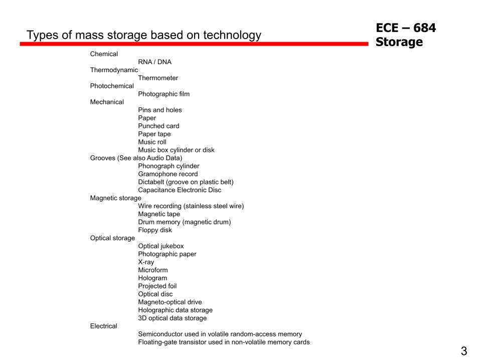
Chemical RNA / DNA
Thermodynamic Thermometer
Photochemical Photographic film
Mechanical Pins and holes Paper Punched card Paper tape Music roll Music box cylinder or disk
Grooves (See also Audio Data) Phonograph cylinder Gramophone record Dictabelt (groove on plastic belt) Capacitance Electronic Disc
Magnetic storage Wire recording (stainless steel wire) Magnetic tape Drum memory (magnetic drum) Floppy disk
Optical storage Optical jukebox Photographic paper X-ray Microform Hologram Projected foil Optical disc Magneto-optical drive Holographic data storage 3D optical data storage
Electrical Semiconductor used in volatile random-access memory Floating-gate transistor used in non-volatile memory cards
4
ECE – 684 Storage Magnetic storage
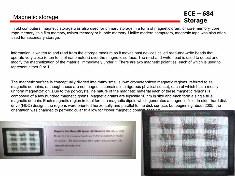
In old computers, magnetic storage was also used for primary storage in a form of magnetic drum, or core memory, core rope memory, thin film memory, twistor memory or bubble memory. Unlike modern computers, magnetic tape was also often used for secondary storage.
Information is written to and read from the storage medium as it moves past devices called read-and-write heads that operate very close (often tens of nanometers) over the magnetic surface. The read-and-write head is used to detect and modify the magnetization of the material immediately under it. There are two magnetic polarities, each of which is used to represent either 0 or 1.
The magnetic surface is conceptually divided into many small sub-micrometer-sized magnetic regions, referred to as magnetic domains, (although these are not magnetic domains in a rigorous physical sense), each of which has a mostly uniform magnetization. Due to the polycrystalline nature of the magnetic material each of these magnetic regions is composed of a few hundred magnetic grains. Magnetic grains are typically 10 nm in size and each form a single true magnetic domain. Each magnetic region in total forms a magnetic dipole which generates a magnetic field. In older hard disk drive (HDD) designs the regions were oriented horizontally and parallel to the disk surface, but beginning about 2005, the orientation was changed to perpendicular to allow for closer magnetic domain spacing.

5
ECE – 684 Storage
A write head magnetizes a region by generating a strong local magnetic field, and a read head detects the magnetization of the regions. Early HDDs used an electromagnet both to magnetize the region and to then read its magnetic field by using electromagnetic induction. Later versions of inductive heads included metal in Gap (MIG) heads and thin film heads. As data density increased, read heads using magnetoresistance (MR) came into use; the electrical resistance of the head changed according to the strength of the magnetism from the platter. Later development made use of spintronics; in read heads, the magnetoresistive effect was much greater than in earlier types, and was dubbed "giant" magnetoresistance (GMR). In today's heads, the read and write elements are separate, but in close proximity, on the head portion of an actuator arm. The read element is typically magneto-resistive while the write element is typically thin-film inductive.
Magnetic storage
The heads are kept from contacting the platter surface by the air that is extremely close to the platter; that air moves at or near the platter speed. The record and playback head are mounted on a block called a slider, and the surface next to the platter is shaped to keep it just barely out of contact. This forms a type of air bearing.

6
ECE – 684 Storage
Floppy Drive
7
ECE – 684 Storage
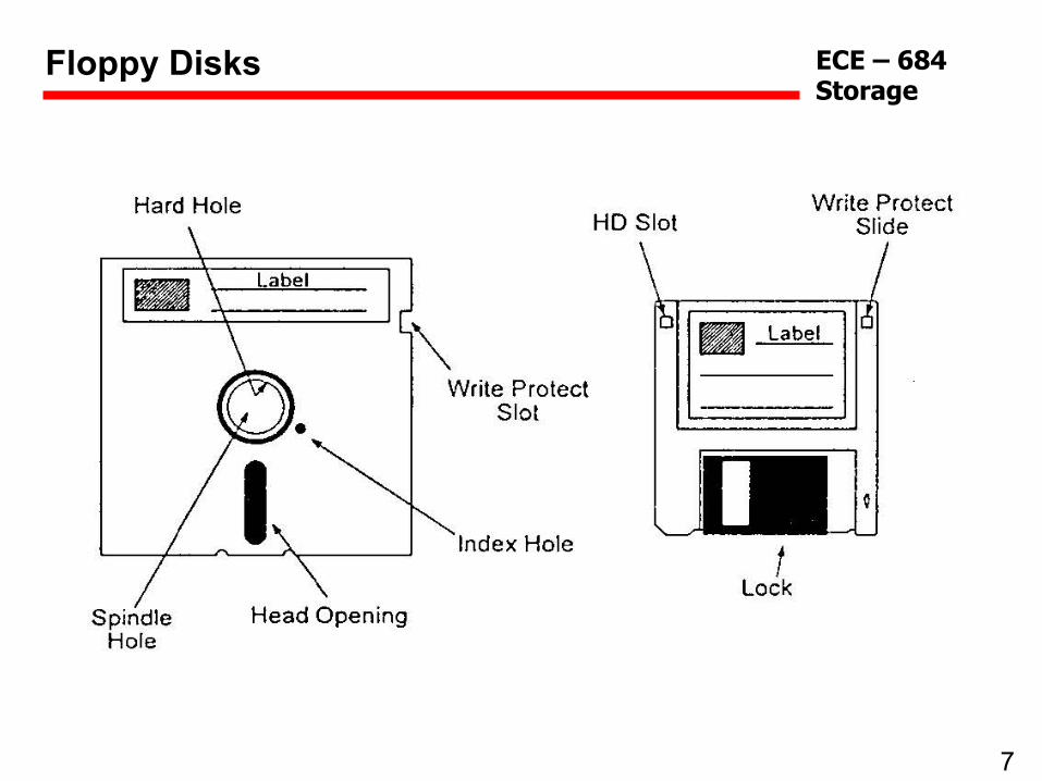
Floppy Disks

8
ECE – 684 Storage
Read/Write Head and Floppy Disk
The read/write head has a coil that generates the magnetic field. The field comes out of the slit and magnetizes the coating of the disk.

9
ECE – 684 Storage
Tracks, Cylinders and Sectors
Every floppy disk is organized into tracks, which in turn are divided into sectors. Within one sector, the bit is the smallest data unit.
Track = Cylinder

10
ECE – 684 Storage
Floppy Disk Parameters
Disk Tracks Sectors/ Track
Cluster Size [Sectors]
Track Width [mm]
Sectors Total
5 ¼” – 360 Kbyte 40 9 2 0.330 720 5 ¼” – 1.2 Mbyte 80 15 1 0.160 2400 3 ½” – 720 Kbyte 80 9 2 0.115 1440 3 ½” – 1.44 Mbyte 80 18 1 0.115 2880
Physical Disk Parameters
Disk Type Capacity TPI BPI [Oersted] Coercivity 5 ¼” Double Density 360 Kbyte 48 5,876 300 5 ¼” Quad Density 720 Kbyte 96 5,876 300 5 ¼” High Density 1.2 Mbyte 96 8,646 600 3 ½” Double Density 720 Kbyte 135 8,717 300 3 ½” High Density 1.44 Mbyte 135 17,434 600

11
ECE – 684 Storage
Hard disk drive
https://www.youtube.com/watch?v=kdmLvl1n82U

12
ECE – 684 Storage
Partitions
A hard disk is divided into partitions, which generally start and end at cylinder boundaries.

13
ECE – 684 Storage
Arrangement of Boot Sector, FATS, Root Directory, Subdirectories and Files
On a floppy disk, from the outside to the inside, are located the boot sector, the two FAT copies and the root directory. These are followed by the data area, which fills the floppy disk up to the innermost cylinder.

14
ECE – 684 Storage
Reading a Byte From Disk

15
ECE – 684 Storage
Disk drive improvements
Hard disk drives for PCs have been improving at an accelerating rate.
observed since the first disk drive. Although the CGRis expected to eventually decline, based on increasedprocessing difficulties in magnetic head and disk me-dia production, laboratory demonstrations of ad-vanced head designs indicate that a head with a ca-pacity of greater than 100 gigabits/in2 is feasiblewithin the near future, representing an increase oftwo or three times, compared with the areal densityof today’s production disk drives.3,4
Although there is no direct analogue to areal den-sity at the storage system level, the trend in floorspace utilization in terabytes/ft2 closely approximatesthat of areal density at the drive level. Figure 2 il-lustrates this trend for storage systems and nearlyparallels the increases indicated by Figure 1 in diskdrive areal density. The enhanced storage capacityper square foot of floor space is the direct result ofdisk drive increases in areal density and, as this trendcontinues into the future, it is expected that nearly104 gigabytes/ft2 will be attained before the year2010.
An alternate method of considering this trend isshown in Figure 3, where the floor space required
to store one terabyte of information over the past45 years is shown to have decreased by more thana factor of 107, similar to increases in server disk driveareal density.
As a further example of the relationship between sys-tems containing multiple disk drives and the evolu-tionary trends in the drives themselves, the volumet-ric density of disk drives is shown in Figure 4. Thisparameter combines disk areal density with the pack-ing efficiency of disks within the drive’s frame as wellas the packaging of the spindle motor, actuator mo-tor, and electronics. Normally, drives with a smallerform factor (FF) exhibit the highest volumetric den-sity, due to more efficient packing. A marked changein the slope of the volumetric density curve indicatesthis effect in larger-form-factor (14-inch and 10.8-inch) drives to 3.5-inch and smaller drives. Areal den-sity also influences this slope change.
At the system level, packing large numbers of drivesin close proximity combined with high volumetricdensity of the drives themselves results in the trendshown in Figure 5. The use of smaller-form-factor
Figure 1 Hard disk drive areal density trend
AFC=ANTIFERROMAGNETICALLY COUPLEDGMR=GIANT MAGNETORESISTIVE
RANGE OFPOSSIBLEVALUES
AR
EAL
DEN
SIT
Y M
EGAB
ITS/
SQ
UA
RE
INC
H
105
104
103
102
10
1
10–1
10–2
10–3
106
19701960 1980 1990 2000 2010PRODUCTION YEAR
IBM RAMAC™ (FIRST HARD DISK DRIVE)
~35 MILLION XINCREASE
1st THIN FILM HEAD
25% CGR
60% CGR
100% CGR
1st MR HEAD
1st GMR HEAD
1st AFC MEDIA
IBM DISK DRIVE PRODUCTSINDUSTRY LAB DEMOS
Figure 2 Storage floor space utilization trend — IBM storage systems
RAW
CAP
ACIT
Y P
ER F
LOO
R S
PAC
E A
REA
, GB
YTES
/SQ
UA
RE
FOO
T
103
102
101
100
10–1
10–2
10–3
10–4
104
19701960 1980 1990 2000 2010PRODUCTION YEAR
IBM RAMAC (FIRST HARD DISK DRIVE)
ESS MOD F
3380
RAMAC 2
IBM ESS MOD 800
25% CGR
60% CGR
RANGE OFPOSSIBLE VALUES
ESS=IBM TOTALSTORAGE™ ENTERPRISE STORAGE SERVER™
IBM SYSTEMS JOURNAL, VOL 42, NO 2, 2003 GROCHOWSKI AND HALEM 339

16
ECE – 684 Storage

17
ECE – 684 Storage
Disk advancements
Magneto Resistive Heads (MR) increase data density over older style (inductive)
With the exception of the spindle motor, every subsection of a drive has seen improvements.
http://en.wikipedia.org/wiki/History_of_IBM_magnetic_disk_drives
Two Part Strategy: 1) Write more data per in2 2) spin the platters faster
Today’s Platter Coercivity ≈3000 Oe

18
ECE – 684 Storage
Figure 3
To ensure that each peak is separate and detectable, peak-detection drives insert extra spaces between peaks, using up disk space that could otherwise store data.

19
ECE – 684 Storage
Figure 4
Because MR read heads madate a separate inductive write head, the read head (b) can be narrower than the write head (a), increasing immunity to errors arising from misalignment.

20
ECE – 684 Storage
Figure 5
Because MR read heads madate a separate inductive write head, the read head (b) can be narrower than the write head (a), increasing immunity to errors arising from misalignment.

21
ECE – 684 Storage
Figure 6
*PRML detection is a digital technique.
*Partial Response Maximum Likelihood
PRML is a method for converting the weak analog signal from the head of a magnetic disk drive into a digital signal. PRML attempts to correctly interpret even small changes in the analog signal, whereas peak detection relies on fixed thresholds. Because PRML can correctly decode a weaker signal it allows higher density recording.
3
Iterative Detection Read Channel Technology in Hard Disk Drives
Achieving Enhanced Performance Through IDRCIDRC technology includes the same PDNP-PRML foundation used by previous read channel electronics. The new enhance-ment is an iterative detector that uses a Low Density Parity Check (LDPC) code to correct additional bit errors using succes-sive iterations of the detector. IDRC calculates reliability values (known as soft information) for each data bit read, then tracks and modifies these values based on a message-passing information algorithm determined by the LDPC code.
Soft InformationIf ideal binary bits are represented in black and white, then soft information can be thought of as a gray scale that describes detected bits. Soft information is calculated to determine the reliability of each bit, and is usually represented as a Log Likelihood Ratio (LLR). This is the natural logarithm of the ratio, based on the probability that the bit is a 1 divided by the probability that the bit is a 0. The LLR format provides accurate manipulation of soft information using only simple addition, subtraction and compare operations. The LLR format also has desirable dynamic range properties that enable LLR values to be represented in a small num-ber system. The final decision of whether a bit is considered a 1 or a 0 is based on whether the sign of the LLR value is positive or negative. An LLR value of zero indicates the complete inability of the system to determine a bit’s binary value.
LLR values can be graphically represent-ed by bars. Bars above the zero reference line are considered BIT=1. Bars below the zero reference line are considered BIT=0. This is illustrated in the graph to the left.
Iterative detection schemes are reliant on accurate soft information. A Soft
Output Viterbi Algorithm (SOVA) is typically employed to generate LLR values for each data bit. Since the Viterbi algorithm is based on sequences and not individual bits, the SOVA block must look both forward and backward from a current bit in order to calculate an accurate LLR bit value.
CodingAs illustrated below, three levels of coding are used in the IDRC data path. This particular ordering of codes is a recent development in the drive industry and is referred to as reverse concatenation. Older hard disk drives used a forward concatenation scheme where the Modulation and Reed-Solomon code blocks are swapped. Reverse concatenation results in a more efficient coding structure and is also an enabling component for the move to iterative detection. Each of these coding levels has an important role in the function of the read channel.
Reliable BIT=1
LLR Format
Unreliable BIT=1
Reliable BIT=0
Unreliable BIT=0
Mod
ulatio
nCo
de
Reed
-Solo
mon
FEC
Code
Inne
r Cod
e(L
DPC)
10110
Sequence of signal processing For disk drives using IDRC** ß
** Iterative Detection Read Channel *** Pattern dependent noise predictive PRML

22
ECE – 684 Storage
Disk drives store bits as a series of alternating polarities between magnetic transitions on a platter. These transitions represent encoded data sequences. As a platter spins (at a constant rate), a read head detects changes in magnetic flux at specified clock times. The read head is a thin-film magnetoresistive (MR) device that changes resistance in the presence of an external magnetic field. A constant current through or a constant voltage across the head causes a voltage or current change that’s proportional to the applied magnetic field. A head preamp amplifies the voltage by a factor to 100 to 300, which brings the signal from microvolts to millivolts. The amplified signal goes to a read-channel IC for signal processing, bit extraction, clock extraction, and error correction. A disk drive has one channel per side of a platter, so a three-platter drive has six read (and six write) channels. The read-channel IC equalizes and filters the incoming signal from the preamp, then digitizes the signal, typically with 6-bit resolution. The ADC in the read-channel IC typically takes four samples per clock period, and the digitized waveform typically represents 6 to 9 bits, depending on the IC’s design. Because each set of samples represents a signal formed by a sequence of bits on a track, the digitized signal is called a partial response. A Viterbi detector runs a maximum-likelihood algorithm that compares a digitized signal to possible bit sequences and tries to figure out the most likely sequence of bits that could have produced that waveform. Hence, the read channel is called a partial response maximum likelihood (PRML) channel. The Viterbi detector’s serial output gets converted into a parallel data stream and goes to the disk drive’s controller IC. The data, now in parallel form, represents the encoded and scrambled data originally written on the disk. Typically, every 16 bits of user data requires 17 bits on the platter. The extra bit helps the read-channel IC extract a clock signal from the data. This technique is similar to clocking schemes used in data-communications protocols. The extra bit (a logic 1) can split long sequences of zeroes, which hinder the clock extraction process. A phase-locked loop (PLL) synchronizes the extracted clock signal to the rotation of the platter. After the read-channel IC decodes the 17 bits into 16 bits of user data, it descrambles the bits and sends them to the hard-drive’s controller. The controller formats the data for the drive’s I/O bus (SCSI, ATA, Ultra-ATA, Fibre Channel, or IEEE 1394), which transfers data to and from the host computer.—Martin Rowe
How Disk Drives Read Bits

23
ECE – 684 Storage
Block Coding Techniques
Reed Solomon block codes are used in: - Storage devices (including tape, Compact Disk, DVD, barcodes, etc) - Wireless or mobile communications (including cellular telephones, microwave links, etc) - Satellite communications - Digital television / DVB - High-speed modems such as ADSL, xDSL, etc.

24
ECE – 684 Storage
TC94A14F/FA/FB is a single-chip processor which incorporates the following functions: sync separation protection, interpolation, EFM decoder, error correction, micro controller interface, digital equalizer for use in servo LSI, and servo control circuit. TC94A14F/FA/FB also incorporates a 1-bit DA converter. Combining TC94A14F/FA/FB with digital servo head amp TA2157F/FN enables very simple and completely adjustment-free CD player systems. Features Capable of decoding the text data. Sync pattern detection, sync signal protection, and synchronization can be made correctly. Built-in EFM demodulation circuit and sub code demodulation. Capable of correcting dual C1 correction and quadruple C2 correction using the CIRC correction theoretical format. The TC94A14F/FA/FB respond to variable playback system. Jitter absorbing capacity of ±6 frame. Built-in 16 KB RAM. Built-in digital out circuit. Built-in L/R independent digital attenuator. Audio output responds to bilingual function. Output format for audio out can be selected 32fs, 48fs or 64fs modes. Read-timing-free sub code Q data and capable of synchronous output with audio data. Built-in data slicer and analog PLL (adjustment-free VCO). Capable of automatic adjustment function of focus and tracking servos for loop gain, offset and balance. Built-in RF gain automatic adjustment circuit. Built-in digital equalizer for phase compensation. Built-in RAM for digital equalizer for coefficient, and capable of variable pickup. Built-in focus and tracking servo control circuit. Search control corresponds to every mode and can realize high speed and stable search. Lens-kick and feed-kick are using speed-controlled form. Built-in AFC and APC circuits for CLV servo of disc motor. Built-in anti-defect and anti-shock circuit. Built-in 8 times over sampling digital filter and 1-bit DA converter. Built-in analog filter for 1-bit DA converter. Built-in zero data detection output circuit. The TC94A14F/FA capable of 4 times speed operation. Built-in micro controller interface circuit. CMOS silicon structure and high speed, low power consumption. 64-pin flat package
Toshiba Digital Servo Single-Chip Processor for Use in CD Player

25
ECE – 684 Storage
Coding Techniques [Burst Errors]

26
ECE – 684 Storage
• A disk can be viewed as an array of blocks. In fact, a file system will want to view it at
that logical level.
• However, there's a mapping scheme from logical block address B, to physical address (represented by a track / sector pair.)
• The smallest storage allocation is a block - nothing smaller can be placed on the disk. This results in unused space (internal fragmentation) on the disk, since quite often the data being placed on the disk doesn't need a whole block.
Disk characteristics

27
ECE – 684 Storage
Disk Management
Disk formatting Creates a logical disk from the raw disk. Includes setting aside chunks of the disk for booting, bad blocks, etc. Also provides information needed by the driver to understand its positioning.
Boot block That location on the disk that is accessed when trying to boot
the operating system. It's a well-known location that contains the code that understands how to get at the operating system - generally this code has a rudimentary knowledge of the file system.
Bad blocks The driver knows how to compensate for a bad block on the
disk. It does this by putting a pointer, at the location of the bad block, indicating where a good copy of the data can be found.
Swap Space Management The Operating System requires a contiguous space where it
knows that disk blocks have been reserved for paging. This space is needed because a program can't be given unshared memory unless there's a backing store location for that memory.

28
ECE – 684 Storage
Disk Attachment
Network-attached storage • Network-attached storage (NAS) is storage made available over a network
rather than over a local connection (such as a bus) • NFS and CIFS are common protocols • Implemented via remote procedure calls (RPCs) between host and storage • New iSCSI protocol uses IP network to carry the SCSI protocol

29
ECE – 684 Storage
Storage-Area Network (SAN) • Common in large storage environments (and becoming more common) • Multiple hosts attached to multiple storage arrays - flexible
Disk Attachment

30
ECE – 684 Storage
Reliability
MIRRORING One way to increase reliability is to "mirror" data on a disk. Every piece of data is maintained on two disks - disk drivers must be capable of getting data from either disk. Performance issues: a read is faster since data can be obtained from either disk - writes are slower since the data must be put on both disks.
RAID Redundant Array of Inexpensive Disks: Rather than maintain two copies
of the data, maintain one copy plus parity. For example, four disks contain data, and a fifth disk holds the parity of the XOR of the four data disks. Reads slower than mirroring, writes much slower. But RAID is considerably CHEAPER than mirroring.
DISK STRIPING Disks tend to be accessed unevenly - programs ask for a number of
blocks from the same file, for instance. Accesses can be distributed more evenly by spreading a file out over several disks. This works well with RAID. Thus block 0 is on disk 0, block 1 is on disk 1, block 4 is on disk 0.
Consider how to recover from a failure on these architectures.
31
ECE – 684 Storage
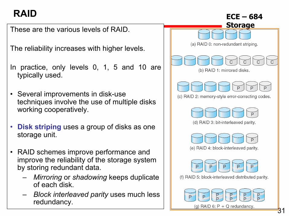
RAID These are the various levels of RAID. The reliability increases with higher levels. In practice, only levels 0, 1, 5 and 10 are
typically used. • Several improvements in disk-use
techniques involve the use of multiple disks working cooperatively.
• Disk striping uses a group of disks as one storage unit.
• RAID schemes improve performance and improve the reliability of the storage system by storing redundant data.
– Mirroring or shadowing keeps duplicate of each disk.
– Block interleaved parity uses much less redundancy.

32
ECE – 684 Storage
RAID
RAID 10 becoming more and more popular.

33
ECE – 684 Storage
Solid State Storage (SSD’s)

34
ECE – 684 Storage
• Solid-state drives are called that specifically because they don’t rely on moving parts or spinning disks.
• Data is saved to a pool of NAND flash. • NAND itself is made up of what are called floating gate transistors.
SSD - FLASH
• Electrons are stored in the floating gate, which then reads as charged “0” or not-charged “1.
• NAND flash is organized in a grid. The entire grid layout is referred to as a block, while the individual rows that make up the grid are called a page.
• Common page sizes are 2K, 4K, 8K, or 16K, with 128 to 256 pages per block. Block size therefore typically varies between 256KB and 4MB.

35
ECE – 684 Storage
SSD - Latency
Access latency for typical storage mediums:

36
ECE – 684 Storage
SSD – SLC, MLC, TLC
NAND is nowhere near as fast as main memory, but it’s multiple orders of magnitude faster than a hard drive. While write latencies are significantly slower for NAND flash than read latencies, they still outstrip traditional spinning media. • Adding more bits per cell of NAND has a significant impact on the memory’s
performance. It’s worse for writes as opposed to reads typical triple-level-cell (TLC) latency is 4x worse compared to single-level cell (SLC) NAND for reads, but 6x worse for writes.
• Erase latencies are also significantly impacted. • The impact isn’t proportional, either — TLC NAND is nearly twice as slow as MLC
NAND, despite holding just 50% more data (three bits per cell, instead of two).

37
ECE – 684 Storage
• The reason TLC NAND is slower than MLC or SLC has to do with how data moves in and out of the NAND cell.
• With SLC NAND, the controller only needs to know if the bit is a 0 or a 1. With MLC NAND, the cell may have four values — 00, 01, 10, or 11. With TLC NAND, the cell can have eight values. Reading the proper value out of the cell requires that the memory controller use a very precise voltage to ascertain whether any particular cell is charged or not.
SSD – SLC, MLC, TLC

38
ECE – 684 Storage
SSD – Block updates
One of the functional limitations of SSDs is that while they can read and write data very quickly to an empty drive, overwriting data is much slower. This is because while SSDs read data at the page and can write at the page level, assuming that surrounding cells are empty, they can only erase data at the block level. This is because the act of erasing NAND flash requires a high amount of voltage. While you can theoretically erase NAND at the page level, the amount of voltage required stresses the individual cells around the cells that are being re-written. Erasing data at the block level helps mitigate this problem. • The only way for an SSD to update an existing page is to copy the contents of the entire
block into memory, erase the block, and then write the contents of the old block + the updated page.
• If the drive is full and there are no empty pages available, the SSD must first scan for blocks that are marked for deletion but that haven’t been deleted yet, erase them, and then write the data to the now-erased page.
• This is why SSDs can become slower as they age — a mostly-empty drive is full of blocks that can be written immediately, a mostly-full drive is more likely to be forced through the entire program/erase sequence.

39
ECE – 684 Storage
SSD – Garbage Collection In the example, the drive has taken advantage of the fact that it can write very quickly to empty pages by writing new values for the first four blocks (A’-D’). It’s also written two new blocks, E and H. Blocks A-D are now marked as stale, meaning they contain information that the drive has marked as out-of-date. During an idle period, the SSD will move the fresh pages over to a new block, erase the old block, and mark it as free space. This means that the next time the SSD needs to perform a write, it can write directly to the now-empty Block X, rather than performing the program/erase cycle.

40
ECE – 684 Storage
SSD - TRIM
The next concept is TRIM. When you delete a file from Windows on a typical hard drive, the file isn’t deleted immediately. Instead, the operating system tells the hard drive that it can overwrite the physical area of the disk where that data was stored the next time it needs to perform a write. This is why it’s possible to undelete files (and why deleting files in Windows doesn’t typically clear much physical disk space until you empty the recycling bin). With a traditional HDD, the OS doesn’t need to pay attention to where data is being written or what the relative state of the blocks or pages is. With an SSD, this matters. The TRIM command allows the operating system to tell the SSD that it can skip rewriting certain data the next time it performs a block erase. This lowers the total amount of data that the drive writes and increases SSD longevity. Both reads and writes damage NAND flash, but writes do far more damage than reads. Fortunately, block-level longevity has not proven to be an issue in modern NAND flash.
41
ECE – 684 Storage
SSD – Wear Leveling Because SSDs write data to pages but erase data in blocks, the amount of data being written to the drive is always larger than the actual update. If you make a change to a 4KB file, for example, the entire block that 4K file sits within must be updated and rewritten. Depending on the number of pages per block and the size of the pages, you might end up writing 4MB worth of data to update a 4KB file. Garbage collection reduces the impact of write amplification, as does the TRIM command. Keeping a significant chunk of the drive free and/or manufacturer overprovisioning can also reduce the impact of write amplification. Wear leveling refers to the practice of ensuring that certain NAND blocks aren’t written and erased more often than others. While wear leveling increases a drive’s life expectancy and endurance by writing to the NAND equally, it can actually increase write amplification. In other to distribute writes evenly across the disk, it’s sometimes necessary to program and erase blocks even though their contents haven’t actually changed. A good wear leveling algorithm seeks to balance these impacts.
Dynamic wear leveling pools erased blocks and selects the block with the lowest erase count for the next write. Static wear leveling selects the target block with the lowest overall erase count, erases the block if necessary, writes new data to the block, and ensures that blocks of static data are moved when their block erase count is below a certain threshold. This additional step of moving data can slow write performance due to overhead on the flash controller, but static wear leveling is considerably more effective than dynamic wear leveling for extending the lifespan of solid state devices.

42
ECE – 684 Storage
SSD - Controller SSD’s often have a DDR3 memory pool to help with managing the NAND itself. Many drives also incorporate single-level cell caches that act as buffers, increasing drive performance by dedicating fast NAND to read/write cycles. Because the NAND flash in an SSD is typically connected to the controller through a series of parallel memory channels, you can think of the drive controller as performing some of the same load balancing work as a high-end storage array — SSDs don’t deploy RAID internally, but wear leveling, garbage collection, and SLC cache management all have parallels in the big iron world. Some drives also use data compression algorithms to reduce total number of writes and improve the drive’s lifespan. The SSD controller handles error correction, and the algorithms that control for single-bit errors have become increasingly complex as time has passed.

43
ECE – 684 Storage
SSD - Future
• NAND flash offers an enormous improvement over hard drives, but it isn’t without its own drawbacks and challenges.
• Drive capacities and price-per-gigabyte are expected to continue to rise and fall respectively, but there’s little chance that SSDs will catch hard drives in price-per-gigabyte.
• Shrinking process nodes are a significant challenge for NAND flash — while most hardware improves as the node shrinks, NAND becomes more fragile. Data retention times and write performance are intrinsically lower for 20nm NAND than 40nm NAND, even if data density and total capacity are vastly improved.
Thus far, SSD manufacturers have delivered better performance by offering faster data standards, more bandwidth, and more channels per controller — plus the use of SLC caches we mentioned earlier. Nonetheless, in the long run, it’s assumed that NAND will be replaced by something else. Both magnetic RAM and phase change memory have presented themselves as candidates, though both technologies are still in early stages and must overcome significant challenges to actually compete as a replacement to NAND. Whether consumers would notice the difference is an open question. If you’ve upgraded from NAND to an SSD and then upgraded to a faster SSD, you’re likely aware that the gap between HDDs and SSDs is much larger than the SSD – SSD gap, even when upgrading from a relatively modest drive. Improving access times from milliseconds to microseconds matters a great deal, but improving them from microseconds to nanoseconds might fall below what humans can realistically perceive in most cases.

44
ECE – 684 Storage
Holographic storage

45
ECE – 684 Storage
Outline
• Volume Holography • Holographic Data Storage Systems
(HDSS) • Technical Challenges • Motivation • Recent Results • Conclusion
https://www.youtube.com/watch?v=d3mVHyCSuZI

46
ECE – 684 Storage
Volume Holography
• In volume holography, we apply an object beam and a reference beam simultaneously on a photosensitive material that records the interference pattern.
• Applying one of these beams to the resultant recording recreates the other.

47
ECE – 684 Storage
Bragg Selectivity
• The hologram is sensitive to the exact recreation of the reference beam. A change in angle, position, or wavelength of the beam will lead to a failure to reconstruct the image.
• The sensitivity increases with thickness of the holographic material.

48
ECE – 684 Storage
Multiplexing
• This can be used to our advantage. We record one object image with our hologram.
• We then change the beam angle, wavelength, or position, until the image disappears, and record another image in the holographic material.
• By this method, multiple object images may be stored in a single piece of holographic material.

49
ECE – 684 Storage
Storing Data
• We can convert binary data to an array of black-and-white pixels with a spatial light modulator (SLM).
• We can store multiple “pages” of data in our holographic crystal.
• We can then read back out our pages via the reference beam.

50
ECE – 684 Storage
Technical Challenges
• Optics • Lasers • SLMs • Readout • Materials

51
ECE – 684 Storage
Optics
• Angle multiplexing requires precision moving optics to change the angle. Wavelength multiplexing requires a tunable wavelength source.
• Solution: shift and coherence multiplexing do not require moving optics.

52
ECE – 684 Storage
Lasers
• Lasers were bulky and expensive. • Solution: modern semiconductor lasers
are small and cheap.

53
ECE – 684 Storage
SLMs
• Creating an SLM that can have a large number of small, independently and rapidly tunable pixels.
• Solutions: modern LCD display technology allows for high-resolution rapidly changeable SLMs. Some researchers are also investigating arrays of MEMS micromirrors.
54
ECE – 684 Storage
Readout
• Need a device that can rapidly readout a page of pixels.
• Solution: a modern CCD array can read the pixels of a page all at once.

55
ECE – 684 Storage
Materials
• Need a holographic recording material with an appropriate (linear) response to light, stability of the recorded pattern, storage capacity, low change of size, and low noise.
• Low-shrinkage photopolymers, particularly the Polaroid/Aprilis material and the Bell Labs/InPhase “Tempest” material. Write once, read many (WORM) materials.
• LiNbO3 doped with Fe. Can be erased and rewritten via exposure to blue light.

56
ECE – 684 Storage
Searching Holographic Storage
• If we recreate the object beam, our hologram reproduces the reference beam.
• If our input beam is similar to several recorded pages, reproduces reference beams with intensity related to degree of match.
• Allows us to look for a match in thousands of images/pages in a single pulse.
• Fingerprints, cytology, other databases

57
ECE – 684 Storage
Modern Developments/Products
• 1995: Hamamatsu/Holoplex Fingerprint Reader. • 2004: InPhase demonstrates prototype for
Tapestry™ system. Plan to start shipping drives by 2006.
• 2005: Optware at work to produce industry standards in 2006 based on Holographic Versatile Disc (HVD) cartridges with 200 GB capacity, credit card-sized Holographic Versatile Card (HVC), and 100 GB HVD disc.
• 2007: Inphase Tapestry products announced; 1.6TB capacity, 128MB/s transfer rates

58
ECE – 684 Storage
InPhase Tapestry specs

59
ECE – 684 Storage
InPhase went out of business in February 2010 and had its assets seized by the state of Colorado for back taxes. The company had reportedly gone through $100 million but the lead investor was unable to raise more capital.
Latest holographic storage developments
In April 2009, GE Global Research demonstrated their own holographic storage material that could allow for discs that utilize similar read mechanisms as those found on Blu-ray Disc players. Their latest breakthrough, shown at an IEEE symposium in Hawaii, is a new micro-holographic material which is 100x more sensitive than its predecessor and ups recording speed to that of Blu-ray discs. GE has been working on holographic technology for over 8 years. Ultimately, the team is working toward micro-holographic discs that can store more than one terabyte, or 1,000 gigabytes of data.
Holo-disc start-up hVault, which slurped the blueprints for InPhase Technologies' holographic storage technology, has vowed to breathe life into the technology, with product promised for next year. Of course, we've already passed the spring of 2012, when hVault originally said it would be shipping the kit. We hear noises from the the International Hologram Manufacturers Association (IHMA) that hVault has a 300GB, 50-year life product entering beta test by the end of 2012, with deliverable product by the summer of 2013. That's later than expected but what's new; the speed of light is 299,792,458 metres/sec, but the speed of holographic storage development is glacial.
60
ECE – 684 Storage
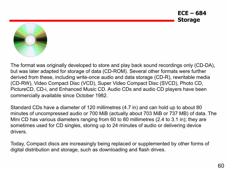
The format was originally developed to store and play back sound recordings only (CD-DA), but was later adapted for storage of data (CD-ROM). Several other formats were further derived from these, including write-once audio and data storage (CD-R), rewritable media (CD-RW), Video Compact Disc (VCD), Super Video Compact Disc (SVCD), Photo CD, PictureCD, CD-i, and Enhanced Music CD. Audio CDs and audio CD players have been commercially available since October 1982. Standard CDs have a diameter of 120 millimetres (4.7 in) and can hold up to about 80 minutes of uncompressed audio or 700 MiB (actually about 703 MiB or 737 MB) of data. The Mini CD has various diameters ranging from 60 to 80 millimetres (2.4 to 3.1 in); they are sometimes used for CD singles, storing up to 24 minutes of audio or delivering device drivers. Today, Compact discs are increasingly being replaced or supplemented by other forms of digital distribution and storage, such as downloading and flash drives.

61
ECE – 684 Storage
CD Drive: Basic design
A schematic of an optical three-beam pick-up of a CD drive is shown in the next figure along with the laser beam route through the system.
The laser beam from the laser diode passes through the diffraction grating to produce two secondary beams needed to maintain correct tracking of the disk. Then, the beam passes polarizing prism (beam splitter) and only the vertical polarized light passes. The light beam is then converted into a parallel beam (by the collimator) and passes through the 1/4-wave plate where the beam polarization plane is rotated by 45 degrees. The beam is then focused onto the disk surface by a lens and a servo-controlled mechanism called 2-axis device. Polarization plane of the reflected beam is rotated by another 45 degrees turning its initial vertical polarization into a horizontal. After a few more reflections, all beams reach six photo detectors: 4 main spot detectors and 2 side spot detectors enabling read-out of the pit information from the disk.

62
ECE – 684 Storage
The figures below illustrate the structure and operating principles of the compact disk. The CD is 12 cm in diameter, 1.2 mm thick, has a center hole 15 mm in diameter, and spins at a constant linear velocity (CLV) or constant angular velocity (CAV). Unlike the hard disk or floppy disk, there is only one track on the optical disk and all data are stored in a spiral of about 2 billion small shallow pits on the surface. There are about 20,000 windings on a CD - all part of the same track. This translates into about 16,000 tracks per inch (TPI) of track density and an areal density of 1 Mb/mm2. The total length of the track on a CD is almost 3 miles (~4.5 km).
Low-magnification (x 32) image of a CD showing an edge of the the data zone. A transparent polycarbonate (PC) polymeric substrate (layer) has the pits molded onto its surface. These pits are the coded data and carry the information. The areas in between the pits, which are 0.9 mm (microns) to 3.3 mm long, are called "lands". The substrate layer is covered with a thin reflective layer of metal (aluminum) and with a protective layer of lacquer. On top of the CD sits the label layer. Summarizing, the compact disk consists of: The label, The protective layer, The reflective layer, The substrate layer.

63
ECE – 684 Storage
A laser beam of approximately 780 nm wave length is focused on the data side of the disk into a spot of about 1 micron in diameter. The laser moves in the radial direction over the fast spinning disk and scans the data track for the intensity of the reflected light.
The data pits are about 0.12 microns (120 nanometers) deep and about 0.6 microns wide. The distance between the neighboring windings of the track is about 1.6 microns. The laser beam scattering occurs when it scans the pits, which translates into a slight drop in intensity of the reflected beam.

64
ECE – 684 Storage
Data encoding
In the compact disk, every transition from pit to land and back is interpreted as 1. No transition means 0, and the length of each land segment represents the number of 0s in the data stream. This principle is illustrated in the figure below, which shows a stream of pits and lands and above it is the corresponding digital data stream.
All codes needed to convert bits into their physical representation and back are called channel codes. The channel code for CD-DA and CD-ROM is called EFM: "eight-to-fourteen modulation". It interprets user's data along with the error correction data, address data, synchronization data, and other content into a stream of "channel bits". The "channel bits" are converted into a binary code and, eventually, turned into pits by the mastering machine. During the play back, the EFM decoder of the CD-ROM works in the opposite direction converting light modulations on the bits into a binary data stream, which is then cleared of any miscellaneous data by the drive's electronics. Unfortunately, the resolution of the CD drive's optics is not sufficient to read directly a sequence of 1s or 0s following each other too closely, i.e. 111111. Another limitation is the maximum length of a given pit or land, in order to leave room for the clock (syncronization) data. Therefore, it was agreed to keep at least two 0s between two 1s and, that the maximum length and pits was limited to 10 bits in a row. These limitations led to the eight-to-fourteen conversion system which represents 8 user-bit bytes with the (minimally required) 14 channel-bit modulation code. Another problem can appear if two 14-bit symbols follow each other, i.e. 1 at the end of one symbol could be too close to 1 at the beginning of another symbol. To solve this issue, 3 special "merge" channel bits are placed between the 14 channel-bit symbols. Thus, for each 8-bit user data 17 channel-bits are used.

65
ECE – 684 Storage
A basic unit of information stored on a CD is called a frame. The frame equals to 24 17-bit symbols combined with the synchronization pattern, a control and display symbol, and 8 error correction symbols. Frames are grouped together to form blocks (also called sectors). Each block has 2352 bytes of user data in the CD-DA standard or 2048 bytes in the CD-ROM standards (due to tighter error correction technique and more error correction bytes). The next figure shows structure of one CD-ROM block.
66
ECE – 684 Storage
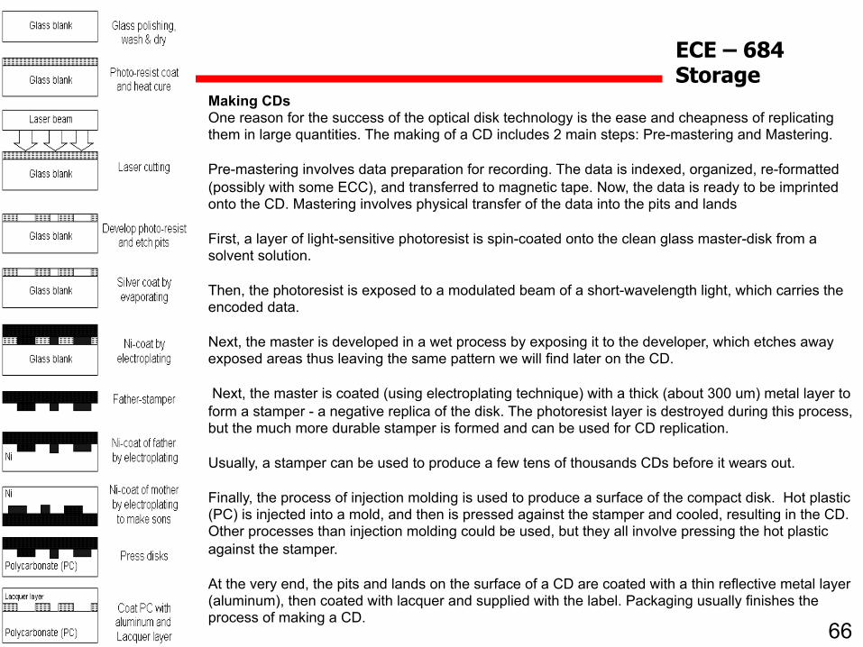
Making CDs One reason for the success of the optical disk technology is the ease and cheapness of replicating them in large quantities. The making of a CD includes 2 main steps: Pre-mastering and Mastering. Pre-mastering involves data preparation for recording. The data is indexed, organized, re-formatted (possibly with some ECC), and transferred to magnetic tape. Now, the data is ready to be imprinted onto the CD. Mastering involves physical transfer of the data into the pits and lands First, a layer of light-sensitive photoresist is spin-coated onto the clean glass master-disk from a solvent solution. Then, the photoresist is exposed to a modulated beam of a short-wavelength light, which carries the encoded data. Next, the master is developed in a wet process by exposing it to the developer, which etches away exposed areas thus leaving the same pattern we will find later on the CD. Next, the master is coated (using electroplating technique) with a thick (about 300 um) metal layer to form a stamper - a negative replica of the disk. The photoresist layer is destroyed during this process, but the much more durable stamper is formed and can be used for CD replication. Usually, a stamper can be used to produce a few tens of thousands CDs before it wears out. Finally, the process of injection molding is used to produce a surface of the compact disk. Hot plastic (PC) is injected into a mold, and then is pressed against the stamper and cooled, resulting in the CD. Other processes than injection molding could be used, but they all involve pressing the hot plastic against the stamper. At the very end, the pits and lands on the surface of a CD are coated with a thin reflective metal layer (aluminum), then coated with lacquer and supplied with the label. Packaging usually finishes the process of making a CD.

67
ECE – 684 Storage
Spin rates and data transfer rate
The X ratings of CD-ROM drives are based on comparison with the first generation drives with the data transfer rates of 150 KB/s or 1X. Today's drives operate at more then 32X boosting data transfer rates beyond 4.8 MB/s, and the improvement has mostly come from the increase in spin rates. The other components have mostly remained unchanged. It seems at this point, that further increase in spindle speed may be impractical due to loss in drive performance. Previously, CD-ROM drives (slower than 12X) were designed on the basis of the constant linear velocity (CLV) principle, where the angular speed of the drive (rpm) was continuously adjusted following the read head to keep the laser spot moving over the disk surface at constant velocity. This provided uniform spacing of the pits along the track and a constant data transfer rate independent of head positioning over the disk. At some point, this principle was sacrificed to keep up with the need for faster and faster motors, which is much easier to achieve with the constant-angular speed motors. Therefore, the newest CD drives operate on constant angular velocity (CAV) principle, like hard drives, for example. Now, the transfer rate is a function of the data radius. This also means that the average data transfer rate of the drive is much lower than the drive's maximum rate specified by its X-rating. This could be partially dealt with by using larger memory buffers, but large memory will also increase the cost of the drive. As an alternative, a hybrid CD drives could be introduced with a constant angular velocity closer to the center of the disk and constant linear velocity closer to the outer diameter of the disk. This should be possible thanks to the digital signal processor chips controlling the drive, which could be reprogrammed relatively easily. The first 1X CD-ROM drive had the data transfer rate equal to 0.15 MB/s. Therefore, 2X drives had 0.3 MB/s rate, 4X drives - 0.6 MB/s, and so up to 12X. For faster drives, which operate on CAV principle, one needs to specify two data transfer rates: minimum and maximum. The next table summarizes this:
68
ECE – 684 Storage
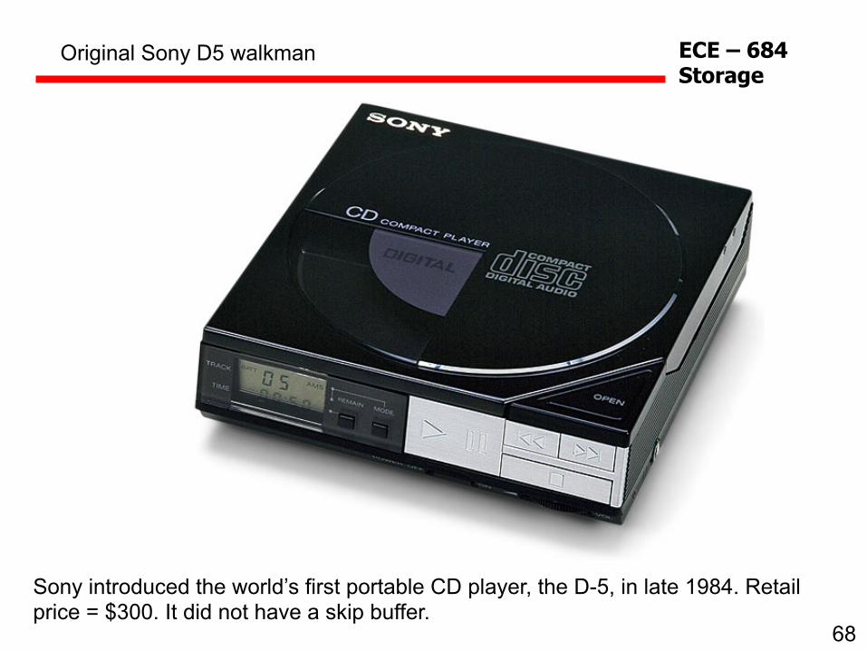
Original Sony D5 walkman
Sony introduced the world’s first portable CD player, the D-5, in late 1984. Retail price = $300. It did not have a skip buffer.
69
ECE – 684 Storage
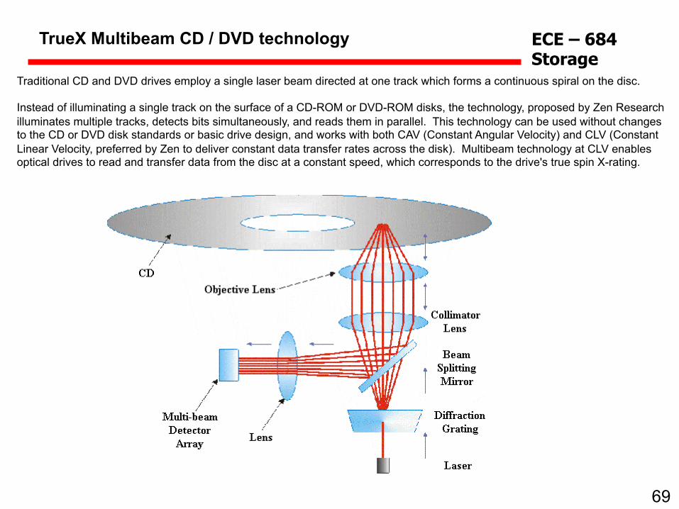
TrueX Multibeam CD / DVD technology
Traditional CD and DVD drives employ a single laser beam directed at one track which forms a continuous spiral on the disc. Instead of illuminating a single track on the surface of a CD-ROM or DVD-ROM disks, the technology, proposed by Zen Research illuminates multiple tracks, detects bits simultaneously, and reads them in parallel. This technology can be used without changes to the CD or DVD disk standards or basic drive design, and works with both CAV (Constant Angular Velocity) and CLV (Constant Linear Velocity, preferred by Zen to deliver constant data transfer rates across the disk). Multibeam technology at CLV enables optical drives to read and transfer data from the disc at a constant speed, which corresponds to the drive's true spin X-rating.
70
ECE – 684 Storage
Blu-ray Disc
March 7, 2005
James Huguenin-Love

71
ECE – 684 Storage
Foundation
• Blu-ray disc (BD) is appropriately named after the blue laser used to write the data
• The first blue laser was developed in 1996 by Shuji Nakamura (Nichia Corporation)
• In 2002, an alliance was formed, called the Blu-ray Disc Association, including the likes of Sony, Samsung, Sharp, Hewlett-Packard, and Royal Phillips
• The “e” is intentionally left out of the name due to trademark restrictions

72
ECE – 684 Storage
Disc Characteristics
• Single layer: 25 GB Dual layer: 50 GB
• Diameter: 120 mm • Thickness: 1.2 mm • Center hole diameter:
15 mm • Uses GaN laser of
wavelength 400 nm • The smaller laser,
compared to the DVD and CD, keeps the process more efficient (~5 mW)
Courtesy Blu-ray Disc Founders “Blu-ray Disc Format White Paper”

73
ECE – 684 Storage
Disc Characteristics
Courtesy Blu-ray Disc Founders “Blu-ray Disc Format White Paper”
• The power conservation allows the development of multi-layer platforms and high-speed recording
• BD-ROM: read-only format
• BD-R and BD-RE: recordable formats (RE: rewritable; R: recordable once)
74
ECE – 684 Storage
Disc Characteristics
Courtesy Blu-ray Disc Founders “Blu-ray Disc Format White Paper”
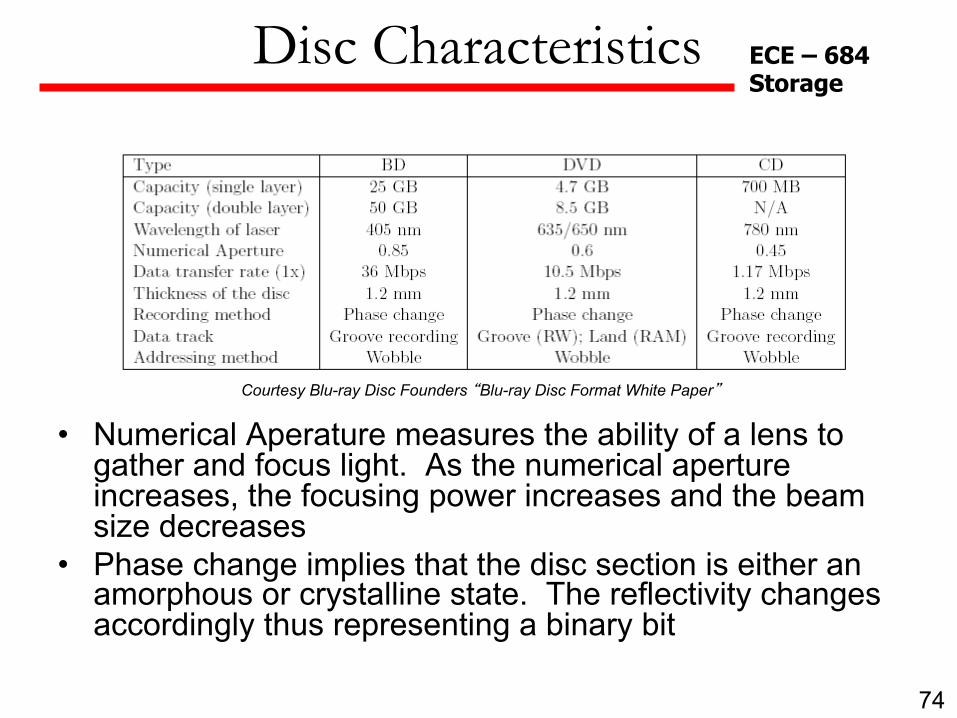
• Numerical Aperature measures the ability of a lens to gather and focus light. As the numerical aperture increases, the focusing power increases and the beam size decreases
• Phase change implies that the disc section is either an amorphous or crystalline state. The reflectivity changes accordingly thus representing a binary bit

75
ECE – 684 Storage
Copy Protection System
• HDTV contains a copyright bit that is detected by the BD recorder. If the broadcast has no copyright bit, then the BD recorder is allowed to store the information
• Uses the Data Encryption Standard (DES) that has a key length of 56 bits
• A Key Block and Disc ID are written into the ROM area to prevent illegal copying
76
ECE – 684 Storage
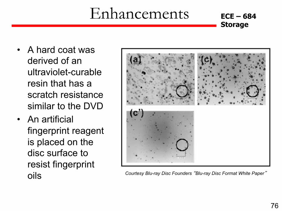
Enhancements
Courtesy Blu-ray Disc Founders “Blu-ray Disc Format White Paper”
• A hard coat was derived of an ultraviolet-curable resin that has a scratch resistance similar to the DVD
• An artificial fingerprint reagent is placed on the disc surface to resist fingerprint oils

77
ECE – 684 Storage
scanning probe memory - Scanning probe-based memories have demonstrated their ability to store data at ultra-high densities, well in excess of 1 Tbit/sq.in. In addition they offer the capability for relatively fast writing and reading, in excess of 1 Mbit/second/tip, combined with very low energy consumption (a few pico Joules of writing energy per bit). nanocrystal memory - charge stored in nanocrystals of silicon ('5nm in size). The devices utilize direct tunneling and storage of electrons in the nanocrystals. The limited size and capacitance of the nanocrystals limit the numbers of stored electrons. The threshold shifts of 0.2–0.4 V with read and write times less than 100’s of a nanosecond at operating voltages below 2.5 V have been obtained experimentally. The retention times are measured in days and weeks, and the structures have been operated in an excess of 109 cycles without degradation in performance. carbon nanotube memory (CNT) - Great potential for storage memory (116 Gb/cm2 ). Small size offers faster switching speeds (100GHz ) and low power. Easy to fabricate: standard semiconductor process. Bistability gives well defined on & off states. Nonvolatile nature: no need to refresh. Faster than SRAM, denser than DRAM, cheaper than flash memory. Have an almost unlimited life, resistant to radiation and magnetism—better than hard drive. DNA memory – While the storage technique does not offer the convenience of random access or being rewriteable, it does have a couple of major advantages. One is its extremely high density – as a result of the information being stored at the molecular level – and the other is its durability. Current research has developed a density of 2 petabytes (1015 bytes) per gram of DNA which, would allow at least 100 million hours of high-definition video to be stored in a teacup. organic memory - High-performance non-volatile memory that can operate under various mechanical deformations such as bending and folding. It consists of a ferroelectric organic field-effect transistor memory operating in p- and n-type dual mode, with excellent mechanical flexibility. The devices contain a ferroelectric poly(vinylidene fluoride-co-trifluoroethylene) thin insulator layer and use a quinoidal oligothiophene derivative (QQT(CN)4) as organic semiconductor. The dual-mode field-effect devices are highly reliable with data retention and endurance of >6,000 s and 100 cycles, respectively, even after 1,000 bending cycles at both extreme bending radii as low as 500 µm and with sharp folding involving inelastic deformation of the device.
Emerging Mass Storage devices


