Masonry support system at Big Wood School · Masonry support system at Big Wood School ... BS...
4
Page 1 Structural Stainless Steel Case Study 06 Structural Stainless Steel Case Study 06 Masonry support system at Big Wood School Big Wood Secondary School in Nottingham is situated on the edge of Bestwood Country Park, with approximately 750 pupils aged between 11 and 16 currently on the roll. As part of the UK Government’s Building Schools for the Future initiative, the school is being completely rebuilt and the first phase of the £18 million development, the construction of three two-storey rectangular teaching blocks (about 40 m x 20 m in plan), was opened in the autumn of 2009. The buildings are brick-clad, structural steelwork frames, with composite floors. The brickwork is supported by a stainless steel masonry support system over the windows (some are in excess of 9 m wide). The support system provides a horizontal ledge for the masonry and is fixed to rectangular hollow edge beams. Material Selection The masonry support system is made from grade 1.4301 (S30400) austenitic stainless steel, which is the grade used for most support systems. It complies with material reference 3 in EN 845-1 [1], the European specification for ancillary components for masonry. The material was specified with a 1D standard mill finish (hot rolled, heat treated and pickled) in accordance with EN 10088-2 [2]. (This is equivalent to a No. 1 finish to ASTM A480.) A stainless steel support system was preferred to a carbon steel system because the latter is likely to corrode in the damp environment encountered in a cavity wall, which might lead to cracking of masonry along mortar joints as well as bulging brickwork. Once a building has been erected, the masonry support system is inaccessible; no cleaning, inspection or maintenance is possible to ensure its structural integrity. Stainless steel has a proven track record of adequate durability in cavity wall environments for the design life of the structure. Another reason that stainless steel was chosen is that if the surface is damaged on site, the transparent ‘passive layer’, which seals the stainless steel from the environment, will instantaneously reform and the lifespan of the component will be unaffected. Stainless steel has a significantly lower thermal conductivity than carbon steel (see Table 1). As masonry support systems are attached to the main structure and pass through the insulated cavity to the outer leaf, the lower thermal conductivity minimises the effect of cold bridging, leading to a more thermally efficient building. Figure 1: General view of Big Wood School Table 1: Typical values for thermal conductivity of building materials Metal Thermal conductivity [W/(mK)] Aluminium 160 Carbon steel 50 Austenitic stainless steel 17 Brick 0.7 Plastic 0.2
Transcript of Masonry support system at Big Wood School · Masonry support system at Big Wood School ... BS...
Page 1 Structural Stainless Steel Case Study 06
Structural Stainless Steel
Case Study 06
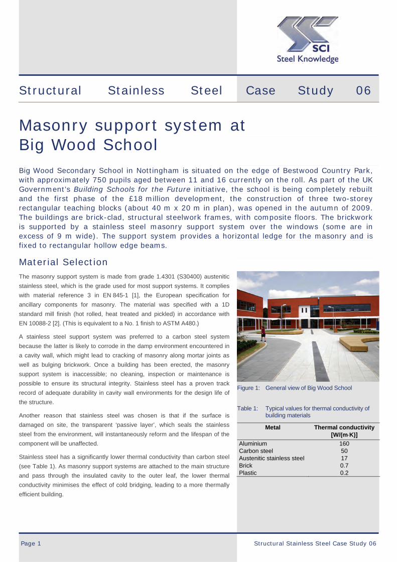
Masonry support system at Big Wood School Big Wood Secondary School in Nottingham is situated on the edge of Bestwood Country Park, with approximately 750 pupils aged between 11 and 16 currently on the roll. As part of the UK Government’s Building Schools for the Future initiative, the school is being completely rebuilt and the first phase of the £18 million development, the construction of three two-storey rectangular teaching blocks (about 40 m x 20 m in plan), was opened in the autumn of 2009. The buildings are brick-clad, structural steelwork frames, with composite floors. The brickwork is supported by a stainless steel masonry support system over the windows (some are in excess of 9 m wide). The support system provides a horizontal ledge for the masonry and is fixed to rectangular hollow edge beams.
Material Selection The masonry support system is made from grade 1.4301 (S30400) austenitic
stainless steel, which is the grade used for most support systems. It complies
with material reference 3 in EN 845-1 [1], the European specification for
ancillary components for masonry. The material was specified with a 1D
standard mill finish (hot rolled, heat treated and pickled) in accordance with
EN 10088-2 [2]. (This is equivalent to a No. 1 finish to ASTM A480.)
A stainless steel support system was preferred to a carbon steel system
because the latter is likely to corrode in the damp environment encountered in
a cavity wall, which might lead to cracking of masonry along mortar joints as
well as bulging brickwork. Once a building has been erected, the masonry
support system is inaccessible; no cleaning, inspection or maintenance is
possible to ensure its structural integrity. Stainless steel has a proven track
record of adequate durability in cavity wall environments for the design life of
the structure.
Another reason that stainless steel was chosen is that if the surface is
damaged on site, the transparent ‘passive layer’, which seals the stainless
steel from the environment, will instantaneously reform and the lifespan of the
component will be unaffected.
Stainless steel has a significantly lower thermal conductivity than carbon steel
(see Table 1). As masonry support systems are attached to the main structure
and pass through the insulated cavity to the outer leaf, the lower thermal
conductivity minimises the effect of cold bridging, leading to a more thermally
efficient building.
Figure 1: General view of Big Wood School
Table 1: Typical values for thermal conductivity of building materials
Metal Thermal conductivity [W/(mK)]
Aluminium 160 Carbon steel 50 Austenitic stainless steel 17 Brick 0.7 Plastic 0.2

Masonry support system at Big Wood School
Structural Stainless Steel Case Study 06 Page 2
Design The masonry support system consists of a continuous angle, with brackets
welded to the vertical leg of the angle at regular intervals. The brackets are
fixed to the structural steel frame. This system is more economical for wider
cavities than a conventional continuous angle system (where the angle has to
span the full width of the cavity) and hence the thickness of the angle can be
reduced, leading to a lighter solution. The precise dimensions of the bracket
and angle are determined by the cavity and loading for each specific project.
In Big Wood School, the bracket angle support system was designed to
support 4.5 kN/m2 load with a 170 mm cavity and the bracket projects below
the supporting structural member. Figures 2 and 3 show two of the
arrangements adopted on the first floor of the Maths and Design block. The
majority of the angles and brackets were manufactured from 4 mm thick plate.
Several special corner pieces were fabricated from 6 mm thick plate.
The design of the system involves modelling the angle as a cantilever while
taking into account the behaviour of the angle between the brackets. It is
carried out in accordance with steel design standards, backed up by extensive
physical testing and industry experience. The vertical deflection at the toe of
the angle relative to the structural steelwork is limited to 1.5 mm.
The supporting steelwork was designed to BS 5950-1 [3] using RAM structural
system software. To avoid excessive movement of the support system, the
structural edge member was designed to minimise deflections and
accommodate torsional forces created by the eccentric load from the
brickwork in accordance with Reference [4].
The brickwork cladding is tied to the inner leaf wall at a maximum horizontal
spacing of 450 mm and within 300 mm above the support angle. The tie
details were checked to BS 5628: Part 1 [5] using wind loadings to BS 6399-2
[6].
Pre-cast panels comprising blockwork with slip bricks were tied back to the
secondary steelwork and cold rolled steel framing to achieve the desired
vertically stack-bonded brickwork effect.
Figure 2: Bracket directly connected to rectangular
hollow edge beam
Figure 3: Bracket connected to angle beneath
rectangular hollow edge beam

Masonry support system at Big Wood School
Page 3 Structural Stainless Steel Case Study 06
Figure 4: Construction of support system shown in Figure 2
Figure 5: Construction of vertically stack bonded brickwork held up by masonry support system
Where the stainless steel support system is bolted to the structural carbon
steel frame, there is a slight risk of bimetallic corrosion if the environment
were to become damp. This would not affect the stainless steel but might
lead to increased corrosion of the carbon steel. To prevent this, the two
metals are isolated from each other by inserting short strips of hi-load DPC
(damp proof course), cut down from rolls, between the back face of the
bracket and the supporting carbon steel rectangular hollow section.
In order to support Nottingham City’s aim to become a zero carbon local
authority within 10 years, Big Wood School incorporates a number of
innovative schemes to reduce carbon emissions and water use. The school
has a renewably fuelled combined heat and power (CHP) plant which
substantially offsets the demand for grid energy, leading to 60 % reduction in
carbon emissions against current UK Building Regulations. (It is the first
education building in the UK to have a pure plant oil CHP plant.) It can sell
electricity to the grid and create revenue through green certificates; energy
consumption and production is displayed in the entrance of the school. The
demand for water from the mains supply is reduced by features such as low-
volume, dual-flush cisterns, automated spray taps and low-flow shower taps
and a rainwater harvesting system collects rainwater from building roofs to be
used to flush toilets.
Fabrication and Installation The masonry support system was fabricated from plate and cold formed into
shape.
The loading on the support system is vertical and static and the angle is
permanently subjected to its full design loading. Tight tolerances have to be
observed because slight deviations in bracket dimensions and installed
position of the brickwork cause relatively large effects on the position of the
loading, on the associated deflections and stresses.
The as-built position of the structural frame was checked for its line and level
before the support system design was finalised and manufacture
commenced. Facility was provided for small adjustments in the vertical and
horizontal directions during installation (Figure 6).
To permit horizontal adjustment along the length of the angle, the system was
designed with 10 mm nominal gaps between individual angles and pre-drilled
horizontal slots in the steelwork to facilitate adjustment of the angle position.
Masonry support system at Big Wood School
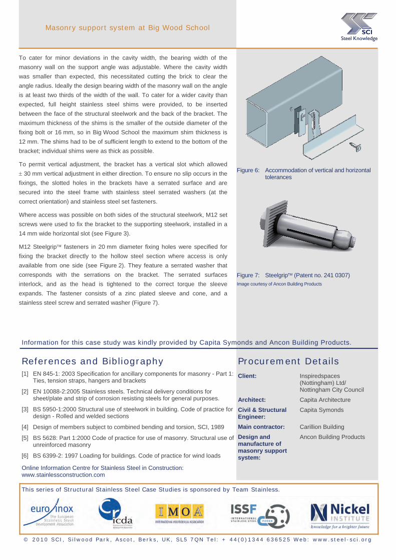
To cater for minor deviations in the cavity width, the bearing width of the
masonry wall on the support angle was adjustable. Where the cavity width
was smaller than expected, this necessitated cutting the brick to clear the
angle radius. Ideally the design bearing width of the masonry wall on the angle
is at least two thirds of the width of the wall. To cater for a wider cavity than
expected, full height stainless steel shims were provided, to be inserted
between the face of the structural steelwork and the back of the bracket. The
maximum thickness of the shims is the smaller of the outside diameter of the
fixing bolt or 16 mm, so in Big Wood School the maximum shim thickness is
12 mm. The shims had to be of sufficient length to extend to the bottom of the
bracket; individual shims were as thick as possible.
To permit vertical adjustment, the bracket has a vertical slot which allowed
30 mm vertical adjustment in either direction. To ensure no slip occurs in the
fixings, the slotted holes in the brackets have a serrated surface and are
secured into the steel frame with stainless steel serrated washers (at the
correct orientation) and stainless steel set fasteners.
Where access was possible on both sides of the structural steelwork, M12 set
screws were used to fix the bracket to the supporting steelwork, installed in a
14 mm wide horizontal slot (see Figure 3).
M12 Steelgrip fasteners in 20 mm diameter fixing holes were specified for
fixing the bracket directly to the hollow steel section where access is only
available from one side (see Figure 2). They feature a serrated washer that
corresponds with the serrations on the bracket. The serrated surfaces
interlock, and as the head is tightened to the correct torque the sleeve
expands. The fastener consists of a zinc plated sleeve and cone, and a
stainless steel screw and serrated washer (Figure 7).
Figure 6: Accommodation of vertical and horizontal
tolerances
Figure 7: Steelgrip (Patent no. 241 0307) Image courtesy of Ancon Building Products
Information for this case study was kindly provided by Capita Symonds and Ancon Building Products.
References and Bibliography [1] EN 845-1: 2003 Specification for ancillary components for masonry - Part 1:
Ties, tension straps, hangers and brackets
[2] EN 10088-2:2005 Stainless steels. Technical delivery conditions for sheet/plate and strip of corrosion resisting steels for general purposes.
[3] BS 5950-1:2000 Structural use of steelwork in building. Code of practice for design - Rolled and welded sections
[4] Design of members subject to combined bending and torsion, SCI, 1989
[5] BS 5628: Part 1:2000 Code of practice for use of masonry. Structural use of unreinforced masonry
[6] BS 6399-2: 1997 Loading for buildings. Code of practice for wind loads
Online Information Centre for Stainless Steel in Construction: www.stainlessconstruction.com
Procurement Details Client: Inspiredspaces
(Nottingham) Ltd/ Nottingham City Council
Architect: Capita Architecture
Civil & Structural Engineer:
Capita Symonds
Main contractor: Carillion Building
Design and manufacture of masonry support
ystem: s
Ancon Building Products
This series of Structural Stainless Steel Case Studies is sponsored by Team Stainless.
© 2010 SCI, S i lwood Park, Ascot , Berks, UK, SL5 7QN Tel: + 44(0)1344 636525 Web: www.stee l-sc i .org