Masonry design for disproportionate collapse requirements ...€¦ · Masonry design for...
13
1 Masonry design for disproportionate collapse requirements under Requirement A3 of The Building Regulations (England & Wales) Introduction This Technical Note was first published in 2005 to provide assistance for the structural design of traditional masonry buildings to resist accidental damage in accordance with requirements given in The Building Regulations for England & Wales and supporting technical guidance provided in Approved Document A (Structure). As the Approved Document was amended in 2010 and again in 2013 this updated Technical Guide includes these latest Building Regulation changes. The Building Regulations Amendments Different requirements for accidental damage were introduced in 2004, when The Building Regulations Requirement A3 (Disproportionate Collapse) was changed. Approved Document A (Structure) to The Building Regulations was revised and subsequently amended in 2004 to reflect this new requirement and to provide guidance on how Requirement A3 could be satisfied. Approved Document A (Structure) was amended again as a 2013 edition and is applicable to England with Wales currently retaining use of the previous 2004 and 2010 amended versions. Principal changes to the 2013 amendment of Approved Document A (Structure) for England are the referencing of CEN based British Standards (Eurocodes) with the corresponding UK National Annexes and supporting British Standards Published Documents (PDs). This has caused related changes to Section 5 of the Approved Document which include the use of Consequence Classes instead of Building Classes and an increase the area of the building at risk to 100m 2 from 70m 2 (Diagram 24 of Approved Document A). BS EN 1996-1-1: 2005+A1: 2012 together with its UK National Annex and British Standards Publication PD 6697: 2010 give guidance for masonry structures in meeting The Building Regulations Requirement A3. Much of the specific guidance given in PD 6697: 2010 for masonry disproportionate collapse design was previously in BS 5628-1: 2005 and its amendments. PD 6697: 2010 is intended to be used in conjunction with BS EN 1996-1-1: 2005+A1: 2012 with its UK National Annex, for engineered masonry design. For actions and combinations of actions (loadings) on structures subjected to disproportionate collapse design requirements, BS EN 1990: 2002+A1: 2005 and BS EN 1991-1-7: 2006 together with the respective UK National Annexes are relevant. The Department for Communities and Local Government (DCLG) issued a Circular Letter on 30 July 2013 to be co-existent with the publication of the Approved Document A 2013 amendments. The Circular Letter explains changes to the new Approved Document A (and C) and also refers to the circumstances where continued and alternative use of BS 5628 and other withdrawn British Standards may be applicable and acceptable to building control authorities. It is considered that the guidance in this revised Technical Note will also be useable in Wales where the 2004 and 2010 editions of Approved Document A (Structure) are currently applicable, because it is not incompatible.
Transcript of Masonry design for disproportionate collapse requirements ...€¦ · Masonry design for...
1
Masonry design for disproportionate collapse requirements under Requirement A3 of The Building Regulations (England & Wales)
Introduction
This Technical Note was first published in 2005 to provide assistance for the structural design of traditional masonry buildings to resist accidental damage in accordance with requirements given in The Building Regulations for England & Wales and supporting technical guidance provided in Approved Document A (Structure). As the Approved Document was amended in 2010 and again in 2013 this updated Technical Guide includes these latest Building Regulation changes.
The Building Regulations Amendments
Different requirements for accidental damage were introduced in 2004, when The Building Regulations Requirement A3 (Disproportionate Collapse) was changed. Approved Document A (Structure) to The Building Regulations was revised and subsequently amended in 2004 to reflect this new requirement and to provide guidance on how Requirement A3 could be satisfied. Approved Document A (Structure) was amended again as a 2013 edition and is applicable to England with Wales currently retaining use of the previous 2004 and 2010 amended versions.
Principal changes to the 2013 amendment of Approved Document A (Structure) for England are the referencing of CEN based British Standards (Eurocodes) with the corresponding UK National Annexes and supporting British Standards Published Documents (PDs). This has caused related changes to Section 5 of the Approved Document which include the use of Consequence Classes instead of Building Classes and an increase the area of the building at risk to 100m2 from 70m2 (Diagram 24 of Approved Document A).
BS EN 1996-1-1: 2005+A1: 2012 together with its UK National Annex and British Standards Publication PD 6697: 2010 give guidance for masonry structures in meeting The Building Regulations Requirement A3. Much of the specific guidance given in PD 6697: 2010 for masonry disproportionate collapse design was previously in BS 5628-1: 2005 and its amendments. PD 6697: 2010 is intended to be used in conjunction with BS EN 1996-1-1: 2005+A1: 2012 with its UK National Annex, for engineered masonry design.
For actions and combinations of actions (loadings) on structures subjected to disproportionate collapse design requirements, BS EN 1990: 2002+A1: 2005 and BS EN 1991-1-7: 2006 together with the respective UK National Annexes are relevant.
The Department for Communities and Local Government (DCLG) issued a Circular Letter on 30 July 2013 to be co-existent with the publication of the Approved Document A 2013 amendments. The Circular Letter explains changes to the new Approved Document A (and C) and also refers to the circumstances where continued and alternative use of BS 5628 and other withdrawn British Standards may be applicable and acceptable to building control authorities.
It is considered that the guidance in this revised Technical Note will also be useable in Wales where the 2004 and 2010 editions of Approved Document A (Structure) are currently applicable, because it is not incompatible.

2
Consequence Classes
Since 2004 the A3 Requirement and its Limits on Application have not provided exemptions for any building structure and all buildings need to comply with the Requirement. This has not changed with the 2010 and 2013 amendments to Approved Document A (Structure). However, the effect of the Approved Document A guidance is to continue to allow houses of up to four storeys to be designed and built as previously, although the Approved Document A simplified sizing rules only cover houses and related buildings design of up to three storeys. The design of hotels, flats, apartments and other residential buildings not exceeding four storeys and the design of five storey single occupancy houses are required to meet slightly enhanced stability needs that are no different from those that existed before publication of the Approved Document A 2010 and 2013 amendments.
One change to A3 guidance is that Building Consequence Classes now replace the previous Building Classes. This is necessary because BS EN 1991-1-7 together with its UK National Annex now refers to Consequence Classes. Table 11of Approved Document A has been re-designated to reflect this change, although in practical terms the technical guidance contained in this table is the same as previously with some editorial and minor text corrections and additions included.
Building Consequence Classes now comprise four classes as 1, 2a (Lower Risk Group), 2b (Upper Risk Group) and 3. This classification is similar in practice to the previous Building Classes.
No specific definition of ‘storey’ is given in Approved Document A, but it has previously been defined elsewhere as: ‘that part of a building that is situated between either:
(a) the top surface of two vertically adjacent floors, or
(b) the top surface of the uppermost floor and the surface covering of the building’.
Basement storeys may be disregarded in the determination of the number of storeys qualifying for the relevant Building Consequence Classes, if they are designed to be sufficiently robust according to Table 11and Note 2 of Approved Document A. The Building Control Alliance (BCA) has published a useful guide that provides interpretation on the determination of the number of storeys as ‘BCA Technical Guidance Note 21 – The Building Regulations 2010 – England & Wales Requirement A3 – Disproportionate Collapse’. The BCA guide advises that ground floor storeys should no longer be excluded from the building storey number count unless satisfactory robustness justification is provided for doing so. It also advises that where more than one basement storey exists in a building that it should be necessary to carry out a risk assessment for the multiple basement arrangement with appropriate robustness measures being incorporated into the building. For a single basement storey building, basement storey count exemption may be considered if Consequence Class 2b robustness measures are applied to the basement storey. This guide was previously published by The National House-Building Council (NHBC) and has been revised for BCA publication along with companion BCA Technical Guidance Note 22.
Table 11 of Approved Document A relating to Requirement A3 defines Building Consequence Classes according to the type and occupancy of the building.
A simple representation of the application of the concept of Building Consequence Classes as applied to single occupancy houses, of various numbers of storeys, is shown in Figure 1 below.
Figure 1: Illustration of the Consequence Class of single occupancy houses from 3 to 6 storeys
2a2a
2b 2b
2b
3 storey over basement
4 storey over basement
5 storey over basement
6 storey over basement
3
Design to satisfy Requirement A3
General
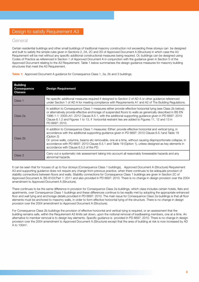
Certain residential buildings and other small buildings of traditional masonry construction not exceeding three storeys can be designed and built to satisfy the simple rules given in Sections 2, 2A, 2C and 2D of Approved Document A (Structure) in which case the A3 Requirement will be met without any specific additional constructional measures being required. Or, buildings can be designed using Codes of Practice as referenced in Section 1 of Approved Document A in conjunction with the guidance given in Section 5 of the Approved Document relating to the A3 Requirement. Table 1 below summarises the design guidance measures for masonry building structures that meet the A3 Requirement.
Table 1: Approved Document A guidance for Consequence Class 1, 2a, 2b and 3 buildings.
Building ConsequenceClasses
Design Requirement
Class 1No specific additional measures required if designed to Section 2 of AD A or other guidance referenced under Section 1 of AD A for meeting compliance with Requirements A1 and A2 of The Building Regulations.
Class 2a
In addition to Consequence Class 1 measures either provide effective horizontal tying (see Class 2b below); or alternatively provide effective anchorage of suspended floors to walls as generically described in BS EN 1996-1-1: 2005+A1: 2012 Clause 8.5.1, with the additional supporting guidance given in PD 6697: 2010 Clause 6.1.2 and Figures 1 to 13, if horizontal restraint ties are added to Figures 11, 12 and 13 in PD 6697: 2010.
Class 2b
In addition to Consequence Class 1 measures: Either: provide effective horizontal and vertical tying, in accordance with the additional supporting guidance given in PD 6697: 2010 Clause 6.5.1and Table 19 (Option 2)Or: prove walls, columns, beams etc removable, one at a time, without causing disproportionate collapse, in accordance with PD 6697: 2010 Clause 6.5.1 and Table 19 (Option 1), unless designed as key elements in accordance with Clause 6.5.2 of the PD.
Class 3Carry out a systematic risk assessment taking into account all reasonably foreseeable hazards and any abnormal hazards.
It can be seen that for houses of up to four storeys (Consequence Class 1 buildings), Approved Document A (Structure) Requirement A3 and supporting guidance does not require any change from previous practice, when there continues to be adequate provision of stability connections between floors and walls. Stability connections for Consequence Class 1 buildings are given in Section 2C of Approved Document A, BS 8103:Part 1: 2011 and also provided in PD 6697: 2010. There is no change in design provision over the 2004 amendment to Approved Document A (Structure).
There continues to be the same difference in provision for Consequence Class 2a buildings, which class includes certain hotels, flats and apartments, over Consequence Class 1 buildings and these differences continue to be readily met by adopting the appropriate enhanced floor and wall tying and anchorage details provided in PD 6697: 2010. The main issue for Consequence Class 2a buildings is that all floor elements must be anchored to masonry walls, in order to form effective horizontal tying of the structure. There is no change in design provision over the 2004 amendment to Approved Document A (Structure).
For Consequence Class 2b buildings the provision of effective horizontal and vertical tying is required, or an assessment that the building remains safe, within the Requirement A3 limits set down, upon the notional removal of loadbearing members, one at a time. An alternative to member removal is to design key elements. Specific guidance is provided in PD 6697: 2010. There is no change in design provision over the 2004 amendment to Approved Document A (Structure) except that the area of building at risk is now increased by AD A to 100m2.
4
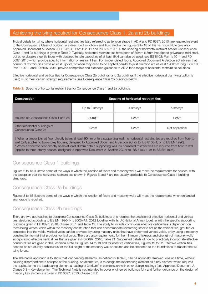
Achieving the tying required for Consequence Class 1, 2a and 2b buildings
Typical details for tying, where horizontal restraint ties (also referred to as tension straps in AD A and PD 6697: 2010) are required relevant to the Consequence Class of building, are described as follows and illustrated in the Figures 2 to 13 of this Technical Note (see also Approved Document A Section 2C, BS 8103: Part 1: 2011 and PD 6697: 2010); the spacing of horizontal restraint ties for Consequence Class 1 and 2a buildings is given in Table 2. Typically, horizontal restraint ties have been of 30mm x 5mm hot dipped galvanised mild steel, but other durable steel tie types with declared tensile capacities of at least 8kN can also be used (see BS 8103: Part 1: 2011 and PD 6697: 2010 which provide specific information on restraint ties). For timber joisted floors, Approved Document A Section 2C advises that horizontal restraint ties cross at least 3 joists, or when they need to be applied parallel to joist direction are at least 1200mm long. BS 8103: Part 1: 2011 and PD 6697: 2010 provide compatible and extended guidance to AD A for a range of horizontal restraint tie solutions.
Effective horizontal and vertical ties for Consequence Class 2b buildings (and 2a buildings if the effective horizontal plan tying option is used) must meet certain strength requirements (see Consequence Class 2b buildings below).
Table 2: Spacing of horizontal restraint ties for Consequence Class 1 and 2a buildings.
Construction Spacing of horizontal restraint ties
Up to 3 storeys 4 storeys 5 storeys
Houses of Consequence Class 1 and 2a 2.0m†* 1.25m 1.25m
Other residential buildings of Consequence Class 2a
1.25m 1.25m Not applicable
† When a timber joisted floor directly bears at least 90mm onto a supporting wall, no horizontal restraint ties are required from floor to wall (only applies to two-storey houses, designed to Approved Document A Section 2C, or to BS 8103-1, or to BS EN 1996).* When a concrete floor directly bears at least 90mm onto a supporting wall, no horizontal restraint ties are required from floor to wall (applies to three-storey houses, designed to Approved Document A Section 2C, or to BS 8103-1, or to BS EN 1996).
Consequence Class 1 buildings
Figures 2 to 13 illustrate some of the ways in which the junction of floors and masonry walls will meet the requirements for houses, with the exception that the horizontal restraint ties shown in Figures 5 and 7 are not usually applicable to Consequence Class 1 building structures.
Consequence Class 2a buildings
Figures 3 to 15 illustrate some of the ways in which the junction of floors and masonry walls will meet the requirements when enhanced anchorage is required.
Consequence Class 2b buildings
There are two approaches to designing Consequence Class 2b buildings; one requires the provision of effective horizontal and vertical ties, designed according to BS EN 1996-1-1: 2005+A1: 2012 together with its UK National Annex together with the specific supporting guidance given in PD 6697: 2010, Clause 6.5.1 and Table 19. The ability to include continuous effective vertical ties is dependent on there being vertical voids within the masonry construction that can accommodate reinforcing steel to act as the vertical ties, grouted or concreted into the voids. Vertical voids can be provided by using masonry units that have preformed vertical voids, or by using a masonry construction format that provides vertical voids. There are also requirements for the minimum thickness and strength of masonry walls incorporating effective vertical ties that are given in PD 6697: 2010, Table 21. Suggested details of how to practically incorporate effective horizontal ties are given in this Technical Note as Figures 14 to 18 and for effective vertical ties, Figures 19 to 22. Effective vertical ties need to be structurally continuous for the full height of the masonry wall or column and be anchored to the foundations to transfer the full tying forces.
The alternative approach is to show that loadbearing elements, as defined in Table 3, can be notionally removed, one at a time, without causing disproportionate collapse of the building. An alternative, is to design the loadbearing element as a key element which requires the application to the loadbearing element a loading of 34kN/m2 in combination with other design loadings (see Approved Document A, Clause 5.3 – Key elements). This Technical Note is not intended to cover engineered buildings fully and further guidance on the design of masonry key elements is given in PD 6697: 2010, Clause 6.5.2.

5
Consideration of the removal of loadbearing elements
When considering the removal of any one of the loadbearing elements, defined in Table 3 below, in a Consequence Class 2b masonry building, the structure above and below must remain stable within the defined limits of collapse, but it does not need to remain serviceable in this theoretical condition. In designing for the notional removal of a loadbearing masonry element, the partial safety factors for material strength that are to be used are reduced, according to BS EN 1996-1-1: 2005+A1: 2012 together with its UK National Annex (see Table NA.1 of UK National Annex). Partial safety factors for actions (loadings) and combinations of actions, including for disproportionate collapse design, are now given in BS EN 1990: 2002+A1: 2005 together with its UK National Annex. Approved Document A (Structure) allows defined collapse of building structures when loadbearing supports, such as a masonry wall or column, has been notionally removed, up to 15% of the floor area of the storey or 100m2 whichever is the lesser (see Approved Document A, Clause 5.1 and Diagram 24 and also BS EN 1991-1-7: 2006 together with its UK National Annex).
Table 3: Loadbearing Elements.
Type of loadbearing element Extent
Beam or slab supporting oneor more columns or a loadbearing wall
Clear span between supports or between a support and the extremity of a member
Column Clear height between horizontal lateral supports
Wall incorporating one or more lateral supports (Note 2)Length between vertical lateral supports orlength between a vertical lateral support and the end of the wall
Wall without lateral supportsLength not exceeding 2.25h anywhere along the wall (for internal walls). Full length (for external walls)
NOTE 1: Under Accidental loading conditions, temporary supports to slabs can be provided by substantial or other adequate partitions capable of carrying the required load.
NOTE 2: Lateral supports to walls can be provided by intersecting or return walls, piers, stiffened sections of wall, substantial non-loadbearing partitions in accordance with PD 6697: 2010 Clause 6.5.6a), b) and c), or by purpose-designed structural elements.
By considering the way in which a structure above a wall that is being notionally removed is able to span over the missing wall, it can usually be demonstrated that collapse can be avoided, or kept to the allowable extent. Examples of how the building structure above and below can be retained after the removal of a loadbearing element are described and illustrated below.
(a) Use the ability of a floor to span, albeit with a large deflection, in the direction at right angles to that for which it was designed, or to span in one direction, rather than in two. See Figure 23.
(b) By virtue of the tying reinforcement in a reinforced concrete floor, allow a floor slab to span two bays of masonry walls, accepting the large deflection that will result. See Figure 24.
(c) Use the ability of a masonry wall to cantilever as a deep beam over the notional opening resulting from consideration of the removal of a wall. See Figure 25.
(d) In a similar way to (c), use the wall above as a deep beam to span over an opening between a corner and the rest of a wall. See Figure 26.
Consequence Class 3 buildings
The risk assessment of Consequence Class 3 buildings is beyond the scope of this Technical Note. Guidance is provided in The Institution of Structural Engineer’s publication ‘Manual for the systematic risk assessment of high-risk structures against disproportionate collapse’.
6
Material alterations to a building
The recommendations in this Technical Note are primarily intended to apply to new buildings design. When material alterations are to be made to an existing building, it may be necessary to comply with Approved Document A (Structure) Requirement A3 in carrying out the structural alterations, but although some of the guidance in this Technical Note may be relevant, the way of doing this is beyond the scope of this Note.
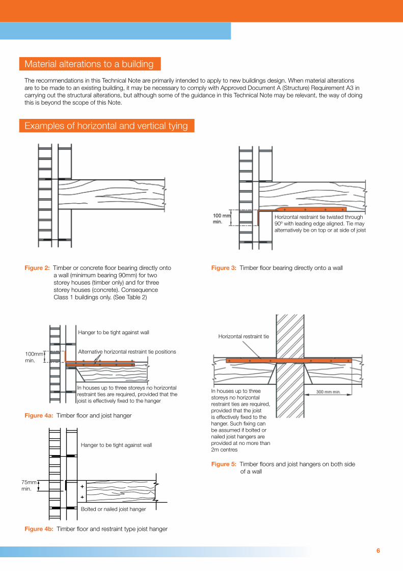
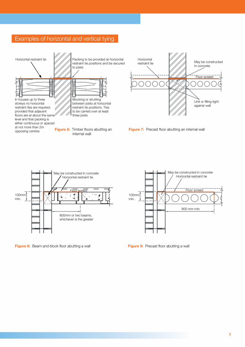
Examples of horizontal and vertical tying
Figure 2: Timber or concrete floor bearing directly onto a wall (minimum bearing 90mm) for two storey houses (timber only) and for three storey houses (concrete). Consequence Class 1 buildings only. (See Table 2)
Figure 3: Timber floor bearing directly onto a wall
Horizontal restraint tie twisted through 90º with leading edge aligned. Tie may alternatively be on top or at side of joist
In houses up to three storeys no horizontal restraint ties are required, provided that the joist is effectively fixed to the hanger
Hanger to be tight against wall
Figure 5: Timber floors and joist hangers on both side of a wall
Horizontal restraint tie
In houses up to three storeys no horizontal restraint ties are required, provided that the joist is effectively fixed to the hanger. Such fixing can be assumed if bolted or nailed joist hangers are provided at no more than 2m centres
Figure 4a: Timber floor and joist hanger
Figure 4b: Timber floor and restraint type joist hanger
Hanger to be tight against wall
Bolted or nailed joist hanger
100mm min.
75mm min.
Alternative horizontal restraint tie positions
7
Examples of horizontal and vertical tying
Figure 6: Timber floors abutting an internal wall
Blocking or strutting between joists at horizontal restraint tie positions. Ties to be carried over at least three joists
Packing to be provided at horizontal restraint tie positions and be secured to joists
In houses up to three storeys no horizontal restraint ties are required, provided that adjacent floors are at about the same level and that packing is either continuous or spaced at not more than 2m opposing centres Figure 7: Precast floor abutting an internal wall
Horizontal restraint tie May be constructed
in concrete
Unit or filling tight against wall
Floor screed
Figure 8: Beam and block floor abutting a wall
May be constructed in concreteHorizontal restraint tie
800mm or two beams,whichever is the greater
100mm min.
Figure 9: Precast floor abutting a wall
100mm min.
May be constructed in concreteHorizontal restraint tie
Floor screed
800 mm min.
Floor screed
Horizontal restraint tie
8
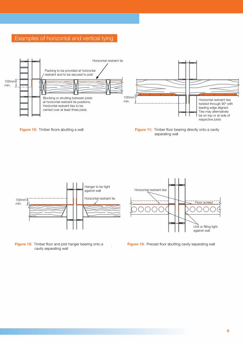
Examples of horizontal and vertical tying
Figure 10: Timber floors abutting a wall
100mm min.
Packing to be provided at horizontal restraint and to be secured to joist
Blocking or strutting between joists at horizontal restraint tie positions. Horizontal restraint ties to be carried over at least three joists
Figure 11: Timber floor bearing directly onto a cavity separating wall
100mm min. Horizontal restraint ties
twisted through 90º with leading edge aligned. Ties may alternatively be on top or at side of respective joists
Figure 12: Timber floor and joist hanger bearing onto a cavity separating wall
Hanger to be tight against wall
Horizontal restraint tie
Figure 13: Precast floor abutting cavity separating wall
Horizontal restraint ties
Floor screed
Unit or filling tight against wall
100mm min.
Horizontal restraint tie

9
Examples of horizontal and vertical tying
Figure 14: Floor ties within a structural screed Figure 15: Floor ties in hollow cores
Figure 16: Perimeter ties within hollow cores Figure 17: Horizontal ties within longitudinal joints
Concrete topping Insitu concrete
Tie bar Internal tie
Tie barInsitu concrete
Longitudinal bar
Tie bar
Concrete infill
10
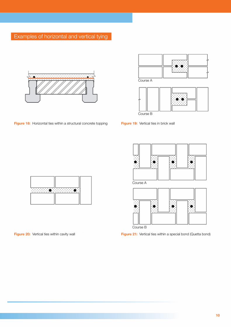
Examples of horizontal and vertical tying
Figure 18: Horizontal ties within a structural concrete topping Figure 19: Vertical ties in brick wall
Figure 20: Vertical ties within cavity wall Figure 21: Vertical ties within a special bond (Quetta bond)
Course A
Course B
Course B
Course A

11
Examples of horizontal and vertical tying
Figure 22: Vertical ties within hollow concrete blocks
Figure 23: Floor alternative spanning paths
Course B
Course A
Instead of
Alternative span
Wall considered tobe removed
originalspan
originalspan
Wall considered tobe removed

12
Examples of horizontal and vertical tying
Figure 24: Catenary concept for the removal of a wall Figure 25: Cantilever approach to removal of a length of wall
Figure 26: Wall spanning over a section considered removed
Wall spans over opening
Opening
13
Documents referred to:
Approved Document A (Structure) 2004 incorporating 2004, 2010 and 2013 amendments.Department for Communities and Local Government
DCLG Circular Letter: Changes to The Building Regulations – Amendments to Approved Document A (Structure) and C (Site preparation and resistance to contaminants and moisture) of 30 July 2013.Department for Communities and Local Government
BS EN 1990: 2002+A1: 2005: Eurocode – Basis of structural design, together with its UK National Annex. British Standards Institution
BS EN 1991-1-7: 2006: Eurocode 1 – Actions on structures – Accidental actions, together with its UK National Annex.British Standards Institution
BS EN 1996-1-1: 2005+A1: 2012: Eurocode 6 – Design of masonry structures, together with its UK National Annex.British Standards Institution
PD 6697: 2010: Recommendations for the design of masonry structures to BS EN 1996-1-1 and BS EN 1996-2.British Standards Institution
BS 5628: Part 1: 2005: Code of practice for the use of masonry –Unreinforced masonry.British Standards Institution
BS 8103: Part 1: 2011: Structural design of low rise buildings – Stability, site investigations, foundations, precast concrete floors and ground floor slabs for housing.British Standards Institution
BCA Technical Guidance Note 21 – The Building Regulations 2010 – England & Wales Requirement A3 – Disproportionate Collapse. Issue 0 Dec 2014.Building Control Alliance
BCA Technical Guidance Note 22 – Assessment of proposed robustness measures following the “Alternative Approach” given in Approved Document A Section 5 paragraph 5.4. Issue 0 Dec 2014.Building Control Alliance
Manual for the systematic risk assessment of high-risk structures against disproportionate collapse. October 2013.The Institution of Structural Engineers
Bibliography:recent:
BS 8103: Part 2: 2013:Structural design of low rise buildings – Masonry walls for housing.British Standards Institution
Manual for the design of plain masonry in building structures to Eurocode 6. February 2008.The Institution of Structural Engineers
Eurocode for masonry EN 1996-1-1 and EN 1996-2 – Guidance and Worked Examples.The International Masonry Society
Practical guide to structural robustness and disproportionate collapse in buildings. October 2010.The Institution of Structural Engineers
Review of international research on structural robustness and disproportionate collapse. October 2011.Department for Communities and Local Government and Centre for the Protection of National Infrastructure
Guidance on robustness and provision against accidental actions.Building Research Establishment Report 200682.Building Research Establishment
Calibration of proposed revised guidance on meeting compliance with the requirements of Building Regulation A3.Department for Communities and Local Government (as ODPM)
New approach to disproportionate collapse. Stuart Alexander.The Structural Engineer Journal. 7 December 2004
Revised Part A of The Building Regulations. Geoff Harding.The Structural Engineer Journal. 18 January 2005
April 2015
Bibliography:historical: