Masoneilan 39004 Series
28
Technical Specifications 05/2013 GE Oil & Gas Masoneilan * 39004 Series High Performance Butterfly Valves
Transcript of Masoneilan 39004 Series
Technical Specifications05/2013
GE Oil & Gas
Masoneilan* 39004 SeriesHigh Performance Butterfly Valves

2 | GE Oil & Gas
Table of ContentsOverview ....................................................................................................................3
Features .....................................................................................................................3
Features: Seat Design ..........................................................................................4
Features: Actuator .................................................................................................5
Model Numbering System..................................................................................6
General Data ............................................................................................................7
Pressure / Temperature Ratings......................................................................8
Body Assembly Data ............................................................................................9
Actuator Data ..........................................................................................................9
Rated Flow Coefficients (CV) ........................................................................... 10
Pressure Recovery Coefficients (FL) ............................................................ 11
Materials of Construction ................................................................................ 12
Weights and Dimensions ................................................................................. 14
Options and Accessories ................................................................................. 24
Sales Offices ........................................................................................Back Cover
39004 High Performance Butterfly Valves | 3
OverviewGE’s Masoneilan 39004 Series High Performance Butterfly Valve (HPBV) is designed for exceptional performance, application flexibility and long service life. This automatic throttling control valve offers benefits such as enhanced sealing, double offset operation, excellent flow characteristics, accurate positioning, and dynamic operation. The 39004 Series features seal designs for soft seal and fire-safe configurations. Combined with the Masoneilan 96/97 Series actuator, the 39004 Series High Performance Butterfly Valve package delivers years of dependable performance in demanding applications.
FeaturesThe 39004 Series High Performance Butterfly Valve incorporates two main features that differentiate it from conventional swing-through butterfly valves – a seal ring and double offset (eccentric) operating principles for the seal and the shaft.
The use of a seal ring eliminates the inherent problem of high sealing forces due to interference fit and the resultant high wear rates caused by liner scraping and scuffing. Additionally, the dynamic, pressure-assisted seal design results in ASME Class VI shutoff rates available throughout the full range of ASME Class 150, 300 and 600 ratings.
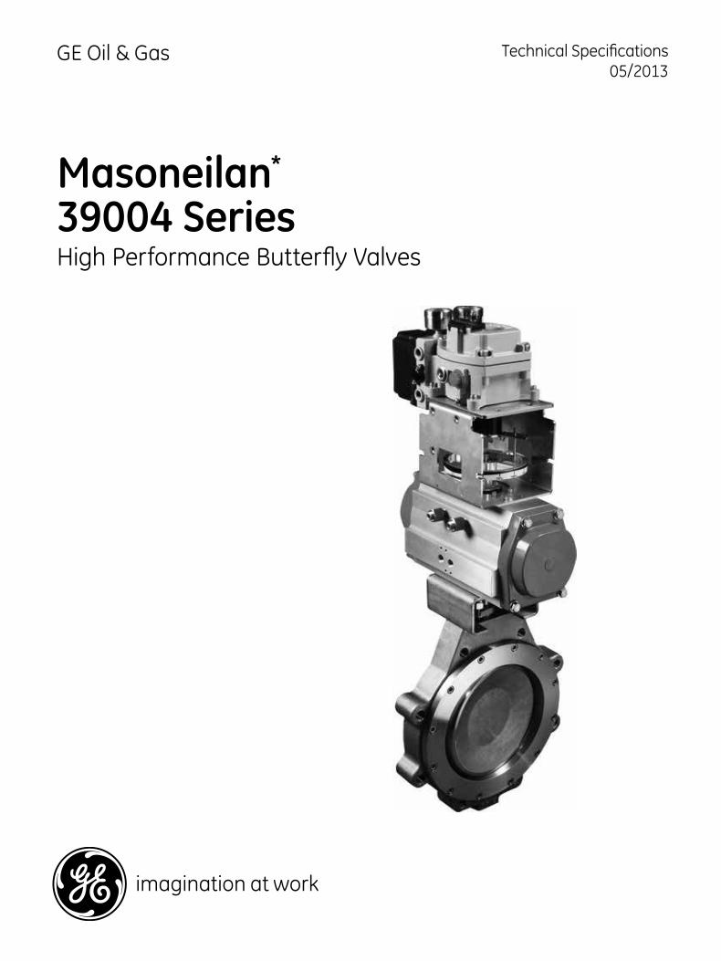
The double offset (eccentric) operating principles shown in Figure 1, apply to both the seal offset, in which the seal ring centerline is offset from the shaft centerline, and shaft offset in which the shaft centerline is offset from the valve centerline. The design allows the disc to lift from the seal quickly due to the camming rotation with respect to the valve/seal centerlines.
These two features contribute to an exceptional high performance butterfly valve that offers many benefits:
Long Seal LifeThe double offset operation lifts the disc from the seal quickly to minimize sliding contact and friction. The result is reduced seal wear as well as lower breakaway and seating torque requirements. This design has been extensively tested maintaining zero leakage shutoff performance throughout the entire life-cycle endurance test.
Fast and Dynamic OperationDouble offset operation eliminates disc-to-seal friction throughout the operating range resulting in fast response to input signals. Also, the disc tends to move in the direction of flow which enables the valve and actuator to maximize allowable operating pressures.
Ease of Installation and MaintenanceThe reduced size and weight of the 39004 Series valve compared to typical rotary and globe products enables fast and easy installation into the pipeline. The seat design also supports easy maintenance by allowing the removal and replacement of the seat retainer without modifying the disc or stem.
Excellent Flow CharacteristicsThe offset disc design provides an approximate equal percentage flow characteristic through its full travel of 90° rotation yielding a Cv ratio of 100:1.
Precise PositioningExtra heavy shafts with keyed ends for actuator mounting offer accurate positioning without lost motion or backlash.
Cost SavingsThe design of the 39004 Series reduces operating torques. As a result , smaller actuation packages are required to operate the valve. Maintenance costs are also reduced through the modular seal design.
Long Service LifeThe PTFE-lined low-friction bearings provide excellent service life while resisting corrosion and distortion from high temperatures and mechanical loading.
Application FlexibilityThe Masoneilan 39004 Series is suited for a wide range of control applications including corrosive chemicals, water, gases, acids, hydrocarbons and other process fluids.
4 | GE Oil & Gas
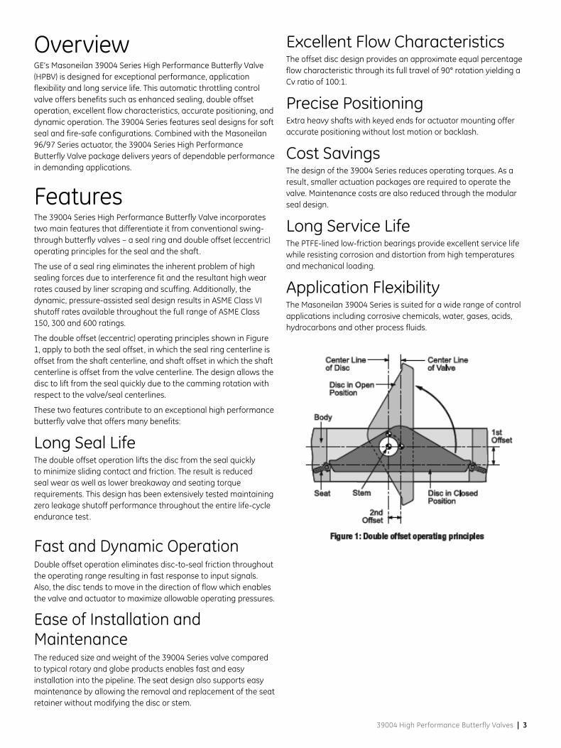
Features - Seat DesignEnergized Soft Seat DesignThe Masoneilan 39004 High Performance Butterfly Valve Includes unique valve seal designs for soft seal and fire-safe configurations.
The 39004 Series soft seal design provides a bi-directional bubble tight shutoff (zero leakage) through the use of a patented seal. This unique, two-part seat assembly includes a resilient energized system that is completely encapsulated by the seat. Advantages include:
• Under higher pressure conditions, the seal is engineered to confine and direct the movement of the soft seal against the disc edge up to the full range of ASME Class 150, 300 and 600 Cold Working Pressures.
• The soft seal is designed for high services with minimal wear and low torque.
• Seal replacement is a simple procedure requiring no special tools.
• Seal energizing system is completely isolated from all contact with line media by the seat. Line media is sealed to zero-leakage in both directions.
• Seat self-adjusts for wear and temperature changes.
• Disc and line pressure energize the seal as pressure is increased. Higher pressures lead to tighter shutoff yielding superior sealing capabilities over longer service life.
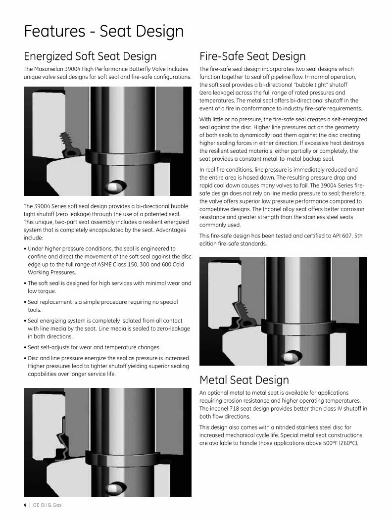
Fire-Safe Seat DesignThe fire-safe seal design incorporates two seal designs which function together to seal off pipeline flow. In normal operation, the soft seal provides a bi-directional “bubble tight” shutoff (zero leakage) across the full range of rated pressures and temperatures. The metal seal offers bi-directional shutoff in the event of a fire in conformance to industry fire-safe requirements.
With little or no pressure, the fire-safe seal creates a self-energized seal against the disc. Higher line pressures act on the geometry of both seals to dynamically load them against the disc creating higher sealing forces in either direction. If excessive heat destroys the resilient seated materials, either partially or completely, the seat provides a constant metal-to-metal backup seal.
In real fire conditions, line pressure is immediately reduced and the entire area is hosed down. The resulting pressure drop and rapid cool down causes many valves to fail. The 39004 Series fire-safe design does not rely on line media pressure to seal; therefore, the valve offers superior low pressure performance compared to competitive designs. The Inconel alloy seat offers better corrosion resistance and greater strength than the stainless steel seats commonly used.
This fire-safe design has been tested and certified to API 607, 5th edition fire-safe standards.
Metal Seat DesignAn optional metal to metal seat is available for applications requiring erosion resistance and higher operating temperatures. The inconel 718 seat design provides better than class IV shutoff in both flow directions.
This design also comes with a nitrided stainless steel disc for increased mechanical cycle life. Special metal seat constructions are available to handle those applications above 500ºF (260ºC).
39004 High Performance Butterfly Valves | 5
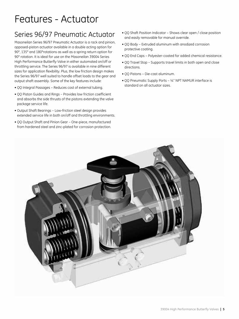
Features - ActuatorSeries 96/97 Pneumatic ActuatorMasoneilan Series 96/97 Pneumatic Actuator is a rack and pinion, opposed-piston actuator available in a double acting option for 90°, 135° and 180°rotations as well as a spring return option for 90° rotation. It is ideal for use on the Masoneilan 39004 Series High Performance Butterfly Valve in either automated on/off or throttling service. The Series 96/97 is available in nine different sizes for application flexibility. Plus, the low friction design makes the Series 96/97 well suited to handle offset loads to the gear and output shaft assembly. Some of the key features include:
• QQ Integral Passages – Reduces cost of external tubing.
• QQ Piston Guides and Rings – Provides low friction coefficient and absorbs the side thrusts of the pistons extending the valve package service life.
• Output Shaft Bearings – Low-friction steel design provides extended service life in both on/off and throttling environments.
• QQ Output Shaft and Pinion Gear – One-piece, manufactured from hardened steel and zinc-plated for corrosion protection.
• QQ Shaft Position Indicator – Shows clear open / close position and easily removable for manual override.
• QQ Body – Extruded aluminum with anodized corrosion protective coating.
• QQ End Caps – Polyester-coated for added chemical resistance.
• QQ Travel Stop – Supports travel limits in both open and close directions.
• QQ Pistons – Die-cast aluminum.
• QQ Pneumatic Supply Ports – ¼” NPT NAMUR interface is standard on all actuator sizes.
6 | GE Oil & Gas
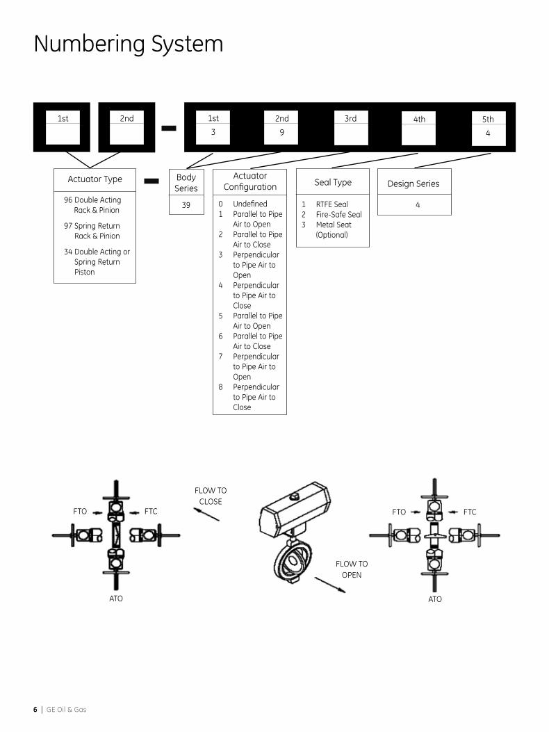
Numbering System
3rd2nd
9
1st
3
1st 2nd
1 RTFE Seal2 Fire-Safe Seal 3 Metal Seat
(Optional)
Seal Type Design Series
4
Actuator Type
96 Double Acting Rack & Pinion
97 Spring Return Rack & Pinion
34 Double Acting or Spring Return Piston
5th
4
4th
39
Body Series
0 Undefined1 Parallel to Pipe
Air to Open2 Parallel to Pipe
Air to Close3 Perpendicular
to Pipe Air to Open
4 Perpendicular to Pipe Air to Close
5 Parallel to Pipe Air to Open
6 Parallel to Pipe Air to Close
7 Perpendicular to Pipe Air to Open
8 Perpendicular to Pipe Air to Close
Actuator Configuration
FTC
FLOW TOOPEN
FTO
FLOW TOCLOSE
ATO
FTCFTO
ATO
39004 High Performance Butterfly Valves | 7
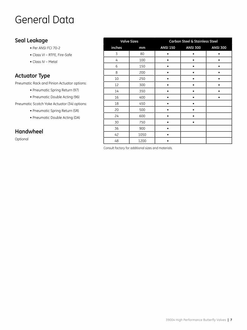
General Data
Seal Leakage • Per ANSI FCI 70-2
• Class VI – RTFE, Fire-Safe
• Class IV – Metal
Actuator TypePneumatic Rack and Pinion Actuator options:
• Pneumatic Spring Return (97)
• Pneumatic Double Acting (96)
Pneumatic Scotch Yoke Actuator (34) options:
• Pneumatic Spring Return (SR)
• Pneumatic Double Acting (DA)
HandwheelOptional
Valve Sizes Carbon Steel & Stainless Steel
inches mm ANSI 150 ANSI 300 ANSI 300
3 80 • • •
4 100 • • •
6 150 • • •
8 200 • • •
10 250 • • •
12 300 • • •
14 350 • • •
16 400 • • •
18 450 • •
20 500 • •
24 600 • •
30 750 • •
36 900 •
42 1050 •
48 1200 •
Consult factory for additional sizes and materials.
8 | GE Oil & Gas
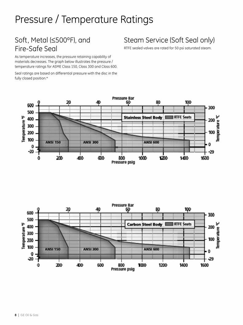
Pressure / Temperature Ratings
Soft, Metal (≤500ºF), and Fire-Safe SealAs temperature increases, the pressure retaining capability of materials decreases. The graph below illustrates the pressure / temperature ratings for ASME Class 150, Class 300 and Class 600.
Seal ratings are based on differential pressure with the disc in the fully closed position.*
Steam Service (Soft Seal only)RTFE sealed valves are rated for 50 psi saturated steam.
39004 High Performance Butterfly Valves | 9
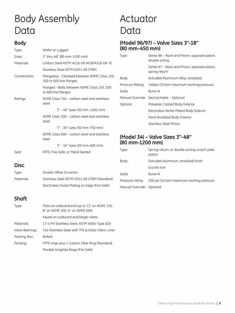
Body AssemblyData
ActuatorData
BodyType: Wafer or Lugged
Sizes: 3” thru 48” (80 mm-1200 mm)
Materials: Carbon Steel ASTM A216 GR WCB/A516 GR 70
Stainless Steel ASTM A351 GR CF8M
Connections: Flangeless - Clamped between ASME Class 150, 300 or 600 line flanges
Flanged - Bolts between ASME Class 150, 300 or 600 line flanges
Ratings: ASME Class 150 - carbon steel and stainless steel
3” - 48” sizes (50 mm-1200 mm)
ASME Class 300 - carbon steel and stainless steel
3” - 30” sizes (50 mm-750 mm)
ASME Class 600 - carbon steel and stainless steel
3” - 16” sizes (50 mm-400 mm)
Seal: RTFE, Fire-Safe, or Metal Seated
DiscType: Double Offset Eccentric
Materials: Stainless Steel ASTM A351 GR CF8M (Standard)
Electroless Nickel Plating on Edge (Fire-Safe)
ShaftType: Flats on outboard end (up to 12” on ASME 150,
8” on ASME 300, 6” on ASME 600)
Keyed on outboard end (larger sizes)
Materials: 17-4 PH Stainless Steel, ASTM A564-Type 630
Valve Bearings: 316 Stainless Steel with TFE & Glass Fabric Liner
Packing Box: Bolted
Packing: PTFE rings plus 1 Carbon Fiber Ring (Standard)
Flexible Graphite Rings (Fire Safe)
(Model 96/97) – Valve Sizes 3”-18” (80 mm-450 mm)Type: Series 96 – Rack and Pinion, opposed-piston,
double acting
Series 97 – Rack and Pinion, opposed-piston, spring return
Body: Extruded Aluminum Alloy, anodized
Pressure Rating: 140psi (10 bar) maximum working pressure
Seals: Buna-N
Manual Override: Declutchable – Optional
Options: Polyester Coated Body Exterior
Electroless Nickel Plated Body Exterior
Hard Anodized Body Exterior
Stainless Steel Pinion
(Model 34) – Valve Sizes 3”-48” (80 mm-1200 mm)Type: Spring-return, or double-acting scotch yoke
piston
Body: Extruded aluminum, anodized finish
Ductile Iron
Seals: Buna-N
Pressure rating: 200 psi (14 bar) maximum working pressure
Manual Override: Optional
10 | GE Oil & Gas
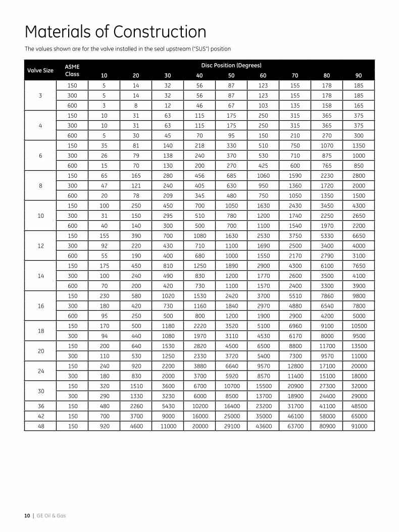
Materials of Construction
Valve Size ASME Class
Disc Position (Degrees)
10 20 30 40 50 60 70 80 90
3
150 5 14 32 56 87 123 155 178 185
300 5 14 32 56 87 123 155 178 185
600 3 8 12 46 67 103 135 158 165
4
150 10 31 63 115 175 250 315 365 375
300 10 31 63 115 175 250 315 365 375
600 5 30 45 70 95 150 210 270 300
6
150 35 81 140 218 330 510 750 1070 1350
300 26 79 138 240 370 530 710 875 1000
600 15 70 130 200 270 425 600 765 850
8
150 65 165 280 456 685 1060 1590 2230 2800
300 47 121 240 405 630 950 1360 1720 2000
600 20 78 209 345 480 750 1050 1350 1500
10
150 100 250 450 700 1050 1630 2430 3450 4300
300 31 150 295 510 780 1200 1740 2250 2650
600 40 140 300 500 700 1100 1540 1970 2200
12
150 155 390 700 1080 1630 2530 3750 5330 6650
300 92 220 430 710 1100 1690 2500 3400 4000
600 55 190 400 680 1000 1550 2170 2790 3100
14
150 175 450 810 1250 1890 2900 4300 6100 7650
300 100 240 490 830 1200 1770 2600 3500 4100
600 70 200 420 730 1100 1570 2400 3300 3900
16
150 230 580 1020 1530 2420 3700 5510 7860 9800
300 180 420 730 1160 1840 2970 4880 6540 7800
600 95 250 500 800 1200 1900 2900 4200 5000
18150 170 500 1180 2220 3520 5100 6960 9100 10500
300 94 440 1080 1970 3110 4530 6170 8000 9500
20150 200 640 1530 2820 4500 6500 8800 11700 13500
300 110 530 1250 2330 3720 5400 7300 9570 11000
24150 240 920 2200 3880 6640 9570 12800 17100 20000
300 180 830 2000 3700 5920 8570 11400 15100 18000
30150 320 1510 3600 6700 10700 15500 20900 27300 32000
300 290 1330 3230 6000 8500 13700 18900 24400 29000
36 150 480 2260 5430 10200 16400 23200 31700 41100 48500
42 150 700 3700 9000 16000 25000 35000 46100 58000 65000
48 150 920 4600 11000 20000 29100 43600 63700 80900 91000
The values shown are for the valve installed in the seal upstream (“SUS”) position
39004 High Performance Butterfly Valves | 11
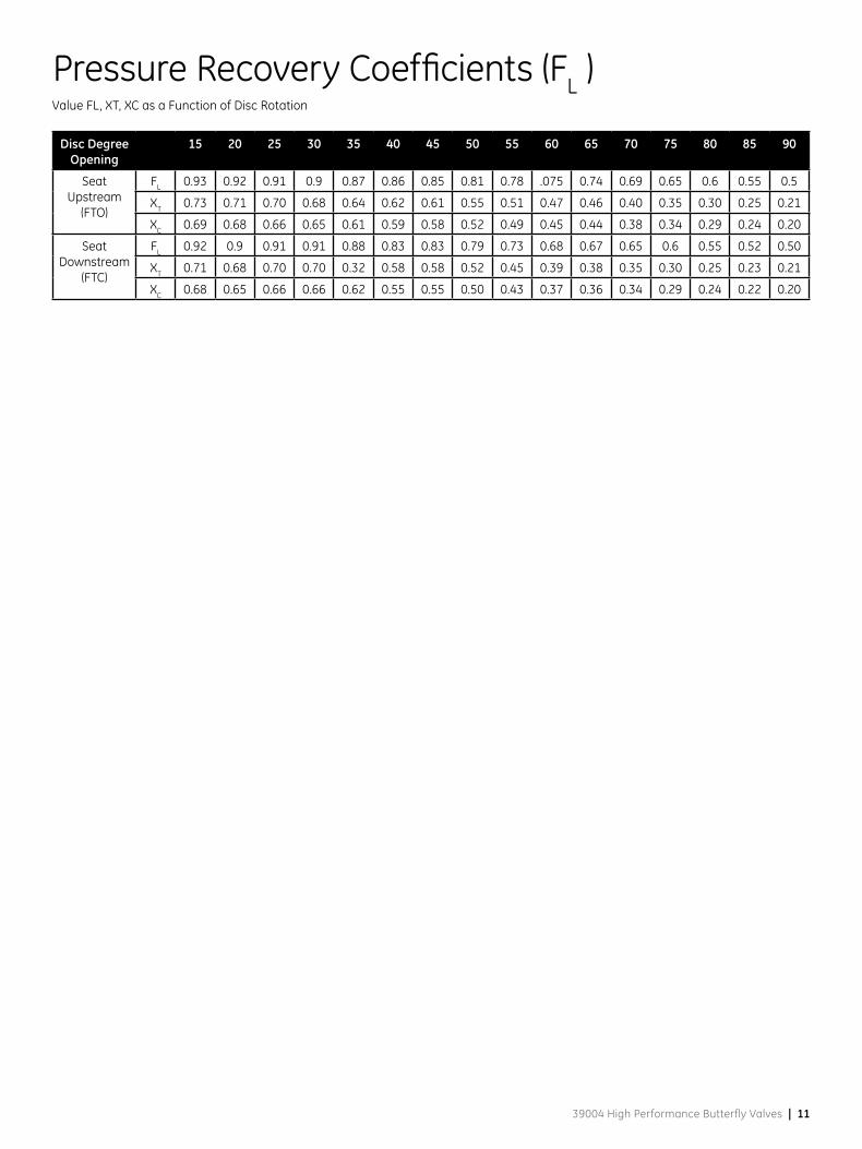
Pressure Recovery Coefficients (FL )
Disc Degree Opening
15 20 25 30 35 40 45 50 55 60 65 70 75 80 85 90
Seat Upstream
(FTO)
FL 0.93 0.92 0.91 0.9 0.87 0.86 0.85 0.81 0.78 .075 0.74 0.69 0.65 0.6 0.55 0.5
XT 0.73 0.71 0.70 0.68 0.64 0.62 0.61 0.55 0.51 0.47 0.46 0.40 0.35 0.30 0.25 0.21
XC 0.69 0.68 0.66 0.65 0.61 0.59 0.58 0.52 0.49 0.45 0.44 0.38 0.34 0.29 0.24 0.20
Seat Downstream
(FTC)
FL 0.92 0.9 0.91 0.91 0.88 0.83 0.83 0.79 0.73 0.68 0.67 0.65 0.6 0.55 0.52 0.50
XT 0.71 0.68 0.70 0.70 0.32 0.58 0.58 0.52 0.45 0.39 0.38 0.35 0.30 0.25 0.23 0.21
XC 0.68 0.65 0.66 0.66 0.62 0.55 0.55 0.50 0.43 0.37 0.36 0.34 0.29 0.24 0.22 0.20
Value FL, XT, XC as a Function of Disc Rotation
12 | GE Oil & Gas
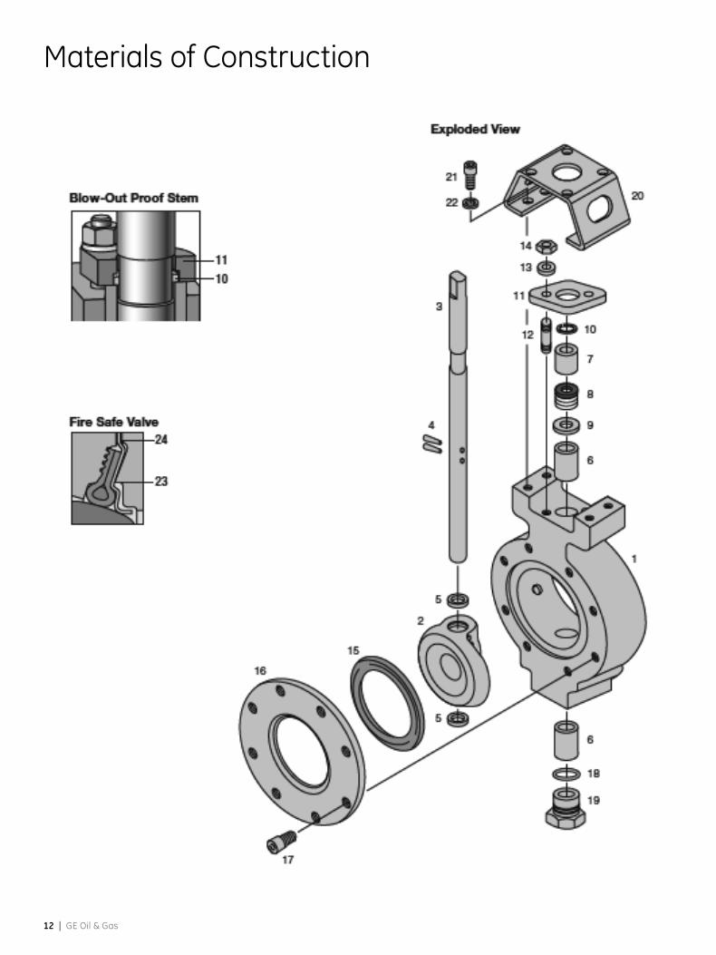
Materials of Construction
39004 High Performance Butterfly Valves | 13
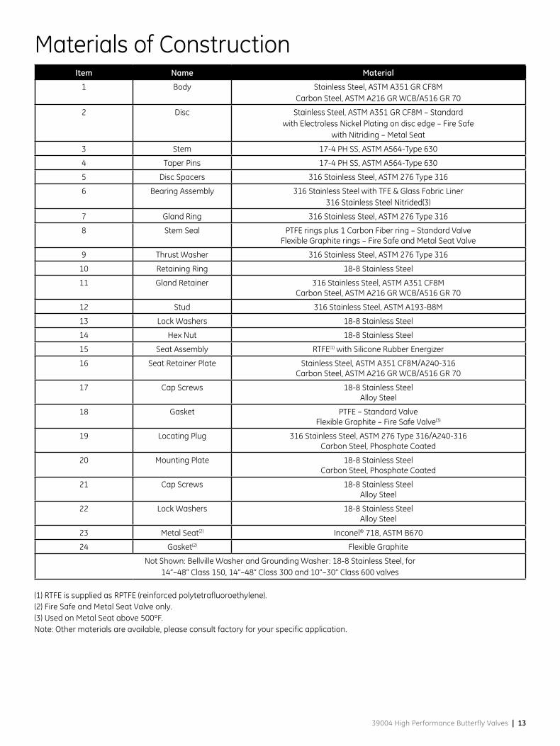
Materials of ConstructionItem Name Material
1 Body Stainless Steel, ASTM A351 GR CF8MCarbon Steel, ASTM A216 GR WCB/A516 GR 70
2 Disc Stainless Steel, ASTM A351 GR CF8M – Standardwith Electroless Nickel Plating on disc edge – Fire Safe
with Nitriding – Metal Seat
3 Stem 17-4 PH SS, ASTM A564-Type 630
4 Taper Pins 17-4 PH SS, ASTM A564-Type 630
5 Disc Spacers 316 Stainless Steel, ASTM 276 Type 316
6 Bearing Assembly 316 Stainless Steel with TFE & Glass Fabric Liner316 Stainless Steel Nitrided(3)
7 Gland Ring 316 Stainless Steel, ASTM 276 Type 316
8 Stem Seal PTFE rings plus 1 Carbon Fiber ring – Standard ValveFlexible Graphite rings – Fire Safe and Metal Seat Valve
9 Thrust Washer 316 Stainless Steel, ASTM 276 Type 316
10 Retaining Ring 18-8 Stainless Steel
11 Gland Retainer 316 Stainless Steel, ASTM A351 CF8MCarbon Steel, ASTM A216 GR WCB/A516 GR 70
12 Stud 316 Stainless Steel, ASTM A193-B8M
13 Lock Washers 18-8 Stainless Steel
14 Hex Nut 18-8 Stainless Steel
15 Seat Assembly RTFE(1) with Silicone Rubber Energizer
16 Seat Retainer Plate Stainless Steel, ASTM A351 CF8M/A240-316Carbon Steel, ASTM A216 GR WCB/A516 GR 70
17 Cap Screws 18-8 Stainless SteelAlloy Steel
18 Gasket PTFE – Standard ValveFlexible Graphite – Fire Safe Valve(3)
19 Locating Plug 316 Stainless Steel, ASTM 276 Type 316/A240-316Carbon Steel, Phosphate Coated
20 Mounting Plate 18-8 Stainless SteelCarbon Steel, Phosphate Coated
21 Cap Screws 18-8 Stainless SteelAlloy Steel
22 Lock Washers 18-8 Stainless SteelAlloy Steel
23 Metal Seat(2) Inconel® 718, ASTM B670
24 Gasket(2) Flexible Graphite
Not Shown: Bellville Washer and Grounding Washer: 18-8 Stainless Steel, for14”–48” Class 150, 14”–48” Class 300 and 10”–30” Class 600 valves
(1) RTFE is supplied as RPTFE (reinforced polytetrafluoroethylene).(2) Fire Safe and Metal Seat Valve only.(3) Used on Metal Seat above 500ºF.Note: Other materials are available, please consult factory for your specific application.

14 | GE Oil & Gas
Series 39004 Dimensions
39004 High Performance Butterfly Valves | 15
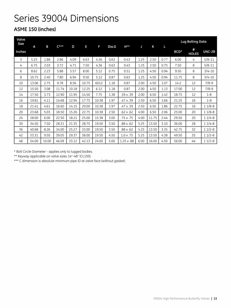
Series 39004 Dimensions
Valve Size
A B C*** D E F Dia.G H** J K LLug Bolting Data
Inches BCD* # HOLES UNC-2B
3 5.25 1.88 2.86 4.09 6.63 4.36 0.63 0.43 1.25 2.50 0.77 6.00 4 5/8-11
4 6.75 2.03 3.72 4.71 7.50 4.36 0.63 0.43 1.25 2.50 0.75 7.50 8 5/8-11
6 8.62 2.23 5.88 5.57 8.00 5.12 0.75 0.51 1.25 4.50 0.94 9.50 8 3/4-10
8 10.75 2.40 7.80 6.94 9.50 5.12 0.87 0.63 1.25 4.50 0.94 11.75 8 3/4-10
10 13.06 2.75 9.78 8.56 10.75 6012 1.18 0.87 2.00 4.50 1.07 14.2 12 7/8-9
12 15.50 3.08 11.74 10.18 12.25 6.12 1.18 0.87 2.00 4.50 1.13 17.00 12 7/8-9
14 17.50 3.73 12.90 11.95 14.50 7.75 1.38 .39 x .39 2.00 6.50 1.42 18.75 12 1-8
16 19.81 4.11 14.68 12.94 17.75 10.38 1.97 .47 x .39 2.50 6.50 1.66 21.25 16 1-8
18 21.41 4.61 16.60 14.15 20.00 10.38 1.97 .47 x .39 2.50 6.50 1.86 22.75 16 1 1/8-8
20 23.68 5.03 18.50 15.26 22.75 10.38 2.50 .62 x .62 4.00 6.50 2.06 25.00 20 1 1/8-8
24 28.00 6.00 22.50 18.21 25.00 15.38 3.00 .75 x .75 4.00 11.75 2.44 29.50 20 1 1/4-8
30 34.50 7.50 28.31 21.35 28.75 19.50 3.50 .88 x .62 5.25 13.50 3.10 36.00 28 1 1/4-8
36 40.68 8.26 34.00 25.27 33.00 19.50 3.50 .88 x .62 5.25 13.50 3.35 42.75 32 1 1/2-8
42 53.31 9.50 39.05 29.37 38.00 19.50 4.50 1.0 x .75 5.25 13.50 4.38 49.50 35 1 1/2-8
48 54.00 10.00 46.09 33.12 42.13 24.00 5.00 1.25 x .88 6.00 16.00 4.50 56.00 44 1 1/2-8
* Bolt Circle Diameter - applies only to lugged bodies.** Keyway applicable on valve sizes 14”-48” (CL150).*** C dimension is absolute minimum pipe ID at valve face (without gasket).
ASME 150 (inches)
16 | GE Oil & Gas
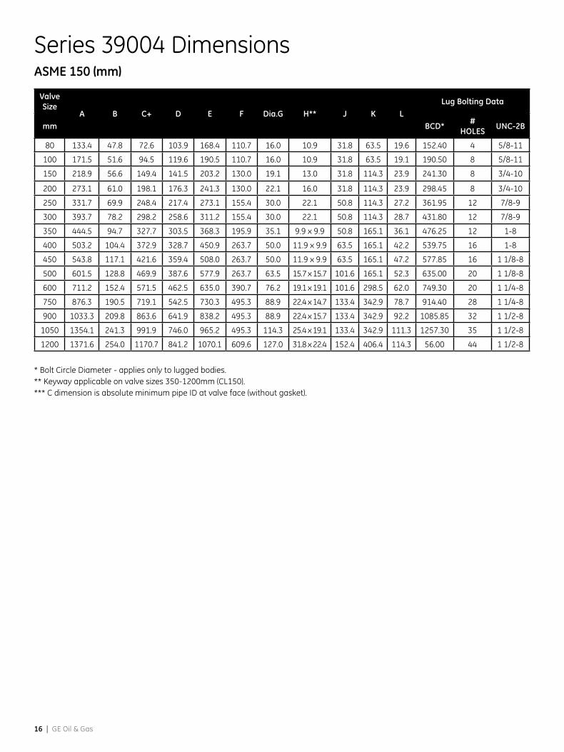
Series 39004 Dimensions
Valve Size
A B C+ D E F Dia.G H** J K LLug Bolting Data
mm BCD* # HOLES UNC-2B
80 133.4 47.8 72.6 103.9 168.4 110.7 16.0 10.9 31.8 63.5 19.6 152.40 4 5/8-11
100 171.5 51.6 94.5 119.6 190.5 110.7 16.0 10.9 31.8 63.5 19.1 190.50 8 5/8-11
150 218.9 56.6 149.4 141.5 203.2 130.0 19.1 13.0 31.8 114.3 23.9 241.30 8 3/4-10
200 273.1 61.0 198.1 176.3 241.3 130.0 22.1 16.0 31.8 114.3 23.9 298.45 8 3/4-10
250 331.7 69.9 248.4 217.4 273.1 155.4 30.0 22.1 50.8 114.3 27.2 361.95 12 7/8-9
300 393.7 78.2 298.2 258.6 311.2 155.4 30.0 22.1 50.8 114.3 28.7 431.80 12 7/8-9
350 444.5 94.7 327.7 303.5 368.3 195.9 35.1 9.9 x 9.9 50.8 165.1 36.1 476.25 12 1-8
400 503.2 104.4 372.9 328.7 450.9 263.7 50.0 11.9 x 9.9 63.5 165.1 42.2 539.75 16 1-8
450 543.8 117.1 421.6 359.4 508.0 263.7 50.0 11.9 x 9.9 63.5 165.1 47.2 577.85 16 1 1/8-8
500 601.5 128.8 469.9 387.6 577.9 263.7 63.5 15.7 x 15.7 101.6 165.1 52.3 635.00 20 1 1/8-8
600 711.2 152.4 571.5 462.5 635.0 390.7 76.2 19.1 x 19.1 101.6 298.5 62.0 749.30 20 1 1/4-8
750 876.3 190.5 719.1 542.5 730.3 495.3 88.9 22.4 x 14.7 133.4 342.9 78.7 914.40 28 1 1/4-8
900 1033.3 209.8 863.6 641.9 838.2 495.3 88.9 22.4 x 15.7 133.4 342.9 92.2 1085.85 32 1 1/2-8
1050 1354.1 241.3 991.9 746.0 965.2 495.3 114.3 25.4 x 19.1 133.4 342.9 111.3 1257.30 35 1 1/2-8
1200 1371.6 254.0 1170.7 841.2 1070.1 609.6 127.0 31.8 x 22.4 152.4 406.4 114.3 56.00 44 1 1/2-8
* Bolt Circle Diameter - applies only to lugged bodies.** Keyway applicable on valve sizes 350-1200mm (CL150).*** C dimension is absolute minimum pipe ID at valve face (without gasket).
ASME 150 (mm)
39004 High Performance Butterfly Valves | 17
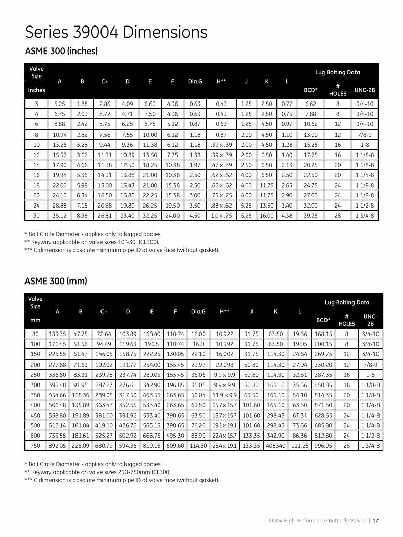
Series 39004 DimensionsASME 300 (inches)
Valve Size
A B C+ D E F Dia.G H** J K LLug Bolting Data
Inches BCD* # HOLES UNC-2B
3 5.25 1.88 2.86 4.09 6.63 4.36 0.63 0.43 1.25 2.50 0.77 6.62 8 3/4-10
4 6.75 2.03 3.72 4.71 7.50 4.36 0.63 0.43 1.25 2.50 0.75 7.88 8 3/4-10
6 8.88 2.42 5.75 6.25 8.75 5.12 0.87 0.63 1.25 4.50 0.97 10.62 12 3/4-10
8 10.94 2.82 7.56 7.55 10.00 6.12 1.18 0.87 2.00 4.50 1.10 13.00 12 7/8-9
10 13.26 3.28 9.44 9.36 11.38 6.12 1.18 .39 x .39 2.00 4.50 1.28 15.25 16 1-8
12 15.57 3.62 11.31 10.89 13.50 7.75 1.38 .39 x .39 2.00 6.50 1.40 17.75 16 1 1/8-8
14 17.90 4.66 11.38 12.50 18.25 10.38 1.97 .47 x .39 2.50 6.50 2.13 20.25 20 1 1/8-8
16 19.94 5.35 14.31 13.88 21.00 10.38 2.50 .62 x .62 4.00 6.50 2.50 22.50 20 1 1/4-8
18 22.00 5.98 15.00 15.43 21.00 15.38 2.50 .62 x .62 4.00 11.75 2.65 24.75 24 1 1/8-8
20 24.10 6.34 16.50 16.80 22.25 15.38 3.00 .75 x .75 4.00 11.75 2.90 27.00 24 1 1/8-8
24 28.88 7.15 20.68 19.80 26.25 19.50 3.50 .88 x .62 5.25 13.50 3.40 32.00 24 1 1/2-8
30 35.12 8.98 26.81 23.40 32.25 24.00 4.50 1.0 x .75 5.25 16.00 4.38 39.25 28 1 3/4-8
* Bolt Circle Diameter - applies only to lugged bodies.** Keyway applicable on valve sizes 10”-30” (CL300).*** C dimension is absolute minimum pipe ID at valve face (without gasket).
Valve Size
A B C+ D E F Dia.G H** J K LLug Bolting Data
mm BCD* # HOLES
UNC-2B
80 133.35 47.75 72.64 103.89 168.40 110.74 16.00 10.922 31.75 63.50 19.56 168.15 8 3/4-10
100 171.45 51.56 94.49 119.63 190.5 110.74 16.0 10.992 31.75 63.50 19.05 200.15 8 3/4-10
150 225.55 61.47 146.05 158.75 222.25 130.05 22.10 16.002 31.75 114.30 24.64 269.75 12 3/4-10
200 277.88 71.63 192.02 191.77 254.00 155.45 29.97 22.098 50.80 114.30 27.94 330.20 12 7/8-9
250 336.80 83.31 239.78 237.74 289.05 155.45 35.05 9.9 x 9.9 50.80 114.30 32.51 387.35 16 1-8
300 395.48 91.95 287.27 276.61 342.90 196.85 35.05 9.9 x 9.9 50.80 165.10 35.56 450.85 16 1 1/8-8
350 454.66 118.36 289.05 317.50 463.55 263.65 50.04 11.9 x 9.9 63.50 165.10 54.10 514.35 20 1 1/8-8
400 506.48 135.89 363.47 352.55 533.40 263.65 63.50 15.7 x 15.7 101.60 165.10 63.50 571.50 20 1 1/4-8
450 558.80 151.89 381.00 391.92 533.40 390.65 63.50 15.7 x 15.7 101.60 298.45 67.31 628.65 24 1 1/4-8
500 612.14 161.04 419.10 426.72 565.15 390.65 76.20 19.1 x 19.1 101.60 298.45 73.66 685.80 24 1 1/4-8
600 733.55 181.61 525.27 502.92 666.75 495.30 88.90 22.4 x 15.7 133.35 342.90 86.36 812.80 24 1 1/2-8
750 892.05 228.09 680.79 594.36 819.15 609.60 114.30 25.4 x 19.1 133.35 406340 111.25 996.95 28 1 3/4-8
* Bolt Circle Diameter - applies only to lugged bodies.** Keyway applicable on valve sizes 250-750mm (CL300).*** C dimension is absolute minimum pipe ID at valve face (without gasket).
ASME 300 (mm)

18 | GE Oil & Gas
Series 39004 DimensionsASME 600 (inches)
Valve Size
A B C+ D E F Dia.G H** J K LLug Bolting Data
Inches BCD* # HOLES UNC-2B
3 5.78 2.22 2.75 5.72 7.00 5.12 0.75 0.51 1.25 4.50 0.90 6.00 4 5/8-11
4 7.00 2.77 3.56 7.04 8.50 5.12 0.87 0.63 1.25 4.50 1.15 7.50 8 5/8-11
6 9.75 3.34 5.38 8.57 9.75 6.12 1.18 0.87 2.00 4.50 1.50 9.50 8 3/4-10
8 11.80 4.23 6.88 10.80 12.25 7.75 1.38 .39 x .39 2.00 6.50 1.90 11.75 8 3/4-10
10 14.09 4.82 8.50 14.62 17.00 10.38 1.97 .47 x .39 2.50 6.50 2.15 14.25 12 7/8-9
12 16.47 5.51 10.12 5.72 18.25 10.38 1.97 .47 x .39 2.50 6.50 2.53 17.00 12 7/8-9
14 18.03 6.09 10.88 17.48 19.75 15.38 2.50 .62 x .62 4.00 11.75 2.90 18.75 12 1-8
16 20.38 7.00 12.62 19.41 21.75 15.38 3.00 .75 x .75 4.00 11.75 3.44 21.25 16 1-8
18 23.15 7.75 14.60 21.05 23.75 19.50 3.50 .88 x .62 5.25 13.50 3.60 22.75 16 1 /18-8
20 25.15 8.50 16.37 23.21 25.75 19.50 4.00 1.0 x .75 5.25 13.50 3.88 25.00 20 1 1/8-8
24 29.38 9.13 19.87 27.71 31.00 24.00 5.00 1.25 x .88 6.00 16.00 3.94 29.50 20 1 1/4-8
* Bolt Circle Diameter - applies only to lugged bodies.** Keyway applicable on valve sizes 8”-24” (CL600).*** C dimension is absolute minimum pipe ID at valve face (without gasket).
Valve Size
A B C+ D E F Dia.G H** J K LLug Bolting Data
mm BCD* # HOLES
UNC-2B
80 146.81 56.39 69.85 145.03 177.80 130.05 19.05 12.954 31.75 114.30 22.86 168.15 8 3/4-10
100 177.80 70.36 90.42 178.82 215.60 130.05 22.10 16.002 31.75 114.30 29.21 215.90 8 7/8-9
150 247.65 84.84 136.65 217.68 247.65 155.45 29.97 22.098 50.80 114.30 38.10 292.10 12 1-8
200 299.72 107.44 174.75 274.32 311.15 196.85 35.05 9.9 x 9.9 50.80 165.10 48.26 349.25 12 1 1/8-8
250 357.89 122.43 215.90 371.35 431.80 263.65 50.04 11.9 x 9.9 63.50 165.10 54.61 431.80 16 1 1/4-8
300 418.34 139.95 257.05 145.29 463.55 263.65 50.04 11.9 x 9.9 65.50 165.10 64.26 488.95 20 1 1/4-8
350 457.96 154.69 276.35 443.99 501.65 390.65 63.50 15.7 x 15.7 101.60 298.45 73.66 527.05 20 1 3/8-8
400 517.65 177.80 320.55 493.01 552.45 390.65 76.20 19.1 x 19.1 101.60 298.45 87.38 603.25 20 1 1/2-8
450 588.01 196.85 390.84 534.67 603.25 495.30 88.90 22.4 x 15.7 133.35 342.90 91.44 654.05 20 1 5/8-8
500 638.81 215.90 415.80 589.53 654.05 495.30 101.60 25.4 x 19.1 133.35 342.90 98.55 723.90 24 1 5/8-8
600 746.25 231.90 504.70 703.83 787.40 609.60 127.00 31.8 x 22.4 152.40 406.40 100.08 838.20 24 1 7/8-8
* Bolt Circle Diameter - applies only to lugged bodies.** Keyway applicable on valve sizes 200-600mm (CL600).*** C dimension is absolute minimum pipe ID at valve face (without gasket).
ASME 600 (mm)
39004 High Performance Butterfly Valves | 19
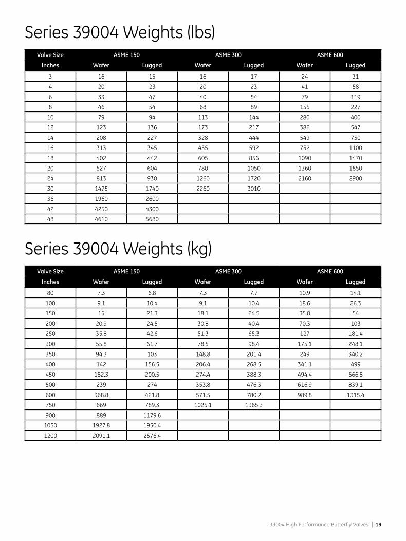
Series 39004 Weights (lbs)Valve Size ASME 150 ASME 300 ASME 600
Inches Wafer Lugged Wafer Lugged Wafer Lugged
3 16 15 16 17 24 31
4 20 23 20 23 41 58
6 33 47 40 54 79 119
8 46 54 68 89 155 227
10 79 94 113 144 280 400
12 123 136 173 217 386 547
14 208 227 328 444 549 750
16 313 345 455 592 752 1100
18 402 442 605 856 1090 1470
20 527 604 780 1050 1360 1850
24 813 930 1260 1720 2160 2900
30 1475 1740 2260 3010
36 1960 2600
42 4250 4300
48 4610 5680
Series 39004 Weights (kg)Valve Size ASME 150 ASME 300 ASME 600
Inches Wafer Lugged Wafer Lugged Wafer Lugged
80 7.3 6.8 7.3 7.7 10.9 14.1
100 9.1 10.4 9.1 10.4 18.6 26.3
150 15 21.3 18.1 24.5 35.8 54
200 20.9 24.5 30.8 40.4 70.3 103
250 35.8 42.6 51.3 65.3 127 181.4
300 55.8 61.7 78.5 98.4 175.1 248.1
350 94.3 103 148.8 201.4 249 340.2
400 142 156.5 206.4 268.5 341.1 499
450 182.3 200.5 274.4 388.3 494.4 666.8
500 239 274 353.8 476.3 616.9 839.1
600 368.8 421.8 571.5 780.2 989.8 1315.4
750 669 789.3 1025.1 1365.3
900 889 1179.6
1050 1927.8 1950.4
1200 2091.1 2576.4
20 | GE Oil & Gas
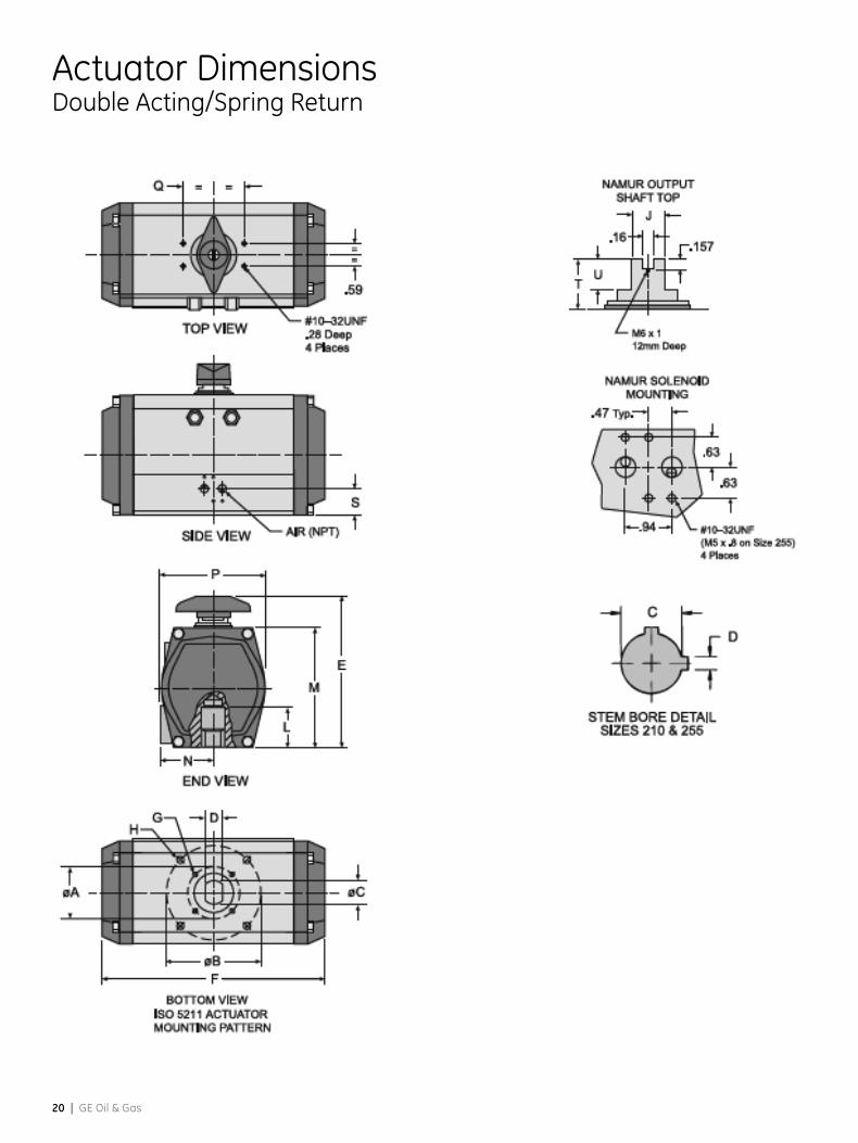
Actuator DimensionsDouble Acting/Spring Return

39004 High Performance Butterfly Valves | 21
Actuator DimensionsSeries 96/97 Dimensions (inches)
Size 63 83 93 119 128 160(1) 210 255(2)
AIR NPT 1/4 1/4 1/4 1/4 1/4 1/4 1/4 1/4
A ISO “F” 1.97 F 05
1.97F 05
1.97F 05
2.76F 07
2.76F 07
N/A 4.92F 12
6.50F 16
B ISO “F” 2.76F 07
2.76F 07
2.76F 07
4.92F 12
4.92F 12
4.92F 12
6.50F 16
7.87 x 4.72Rect.
C 0.55 0.75 0.75 1.18 1.18 1.18 1.97 2.50
D 0.40 0.51 0.51 0.87 0.87 0.87 0.47 0.62
E 4.53 5.43 5.78 7.28 8.09 9.36 11.45 13.35
F 5.58 7.40 9.10 12.40 12.81 15.54 17.80 26.70
G (UNC) 1/4-20 x .32 1/4-20 x .32 1/4-20 x .32 5/16-18 x .46 5/16-18 x .46 N/A 1/2-13 x .78 M16x2 x 28mm
H (UNC) 5/16-18 x .32 5/16-18 x .40 5/16-18 x .40 1/2-13 x .69 1/2-13 x .69 1/2-13 x .75 5/8-11 x 1.11 M16x2 x 28mm
J 0.38 0.50 0.50 1.12 1.12 1.12 1.12 1.12
L 1.38 1.46 1.46 2.20 2.20 2.20 2.76 4.25
M 3.46 4.27 4.61 5.52 6.32 7.80 10.40 11.89
N 1.72 2.02 2.47 2.78 2.88 3.07 4.25 4.75
P 3.11 3.83 1.97 2.37 2.70 6.82 8.83 10.75
Q 1.58 1.58 1.58 1.58 1.58 2.56 2.56 2.56
S 0.89 0.89 1.32 1.64 1.64 1.39 1.44 1.50
T 0.79 0.79 0.79 0.79 0.79 1.18 1.18 1.18
U 0.47 0.47 0.47 0.47 0.47 0.75 0.75 0.75
Note: Double Acting and Spring Return actuators have the same overall dimensions.ISO “F” means mounting flange-drilling pattern.1) Dimensions for Size 160A in table. Size 160B (keyed stem version) has C dimension of 1.38 and D dimension of .39.2) Dimensions for Size 255A in table. Size 255B has C dimension of 3.00 and D dimension of .75.
22 | GE Oil & Gas
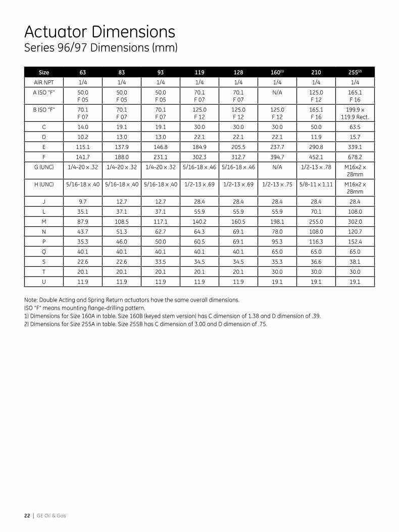
Actuator DimensionsSeries 96/97 Dimensions (mm)
Size 63 83 93 119 128 160(1) 210 255(2)
AIR NPT 1/4 1/4 1/4 1/4 1/4 1/4 1/4 1/4
A ISO “F” 50.0F 05
50.0F 05
50.0F 05
70.1F 07
70.1F 07
N/A 125.0F 12
165.1F 16
B ISO “F” 70.1F 07
70.1F 07
70.1F 07
125.0F 12
125.0F 12
125.0F 12
165.1F 16
199.9 x 119.9 Rect.
C 14.0 19.1 19.1 30.0 30.0 30.0 50.0 63.5
D 10.2 13.0 13.0 22.1 22.1 22.1 11.9 15.7
E 115.1 137.9 146.8 184.9 205.5 237.7 290.8 339.1
F 141.7 188.0 231.1 302.3 312.7 394.7 452.1 678.2
G (UNC) 1/4-20 x .32 1/4-20 x .32 1/4-20 x .32 5/16-18 x .46 5/16-18 x .46 N/A 1/2-13 x .78 M16x2 x 28mm
H (UNC) 5/16-18 x .40 5/16-18 x .40 5/16-18 x .40 1/2-13 x .69 1/2-13 x .69 1/2-13 x .75 5/8-11 x 1.11 M16x2 x 28mm
J 9.7 12.7 12.7 28.4 28.4 28.4 28.4 28.4
L 35.1 37.1 37.1 55.9 55.9 55.9 70.1 108.0
M 87.9 108.5 117.1 140.2 160.5 198.1 255.0 302.0
N 43.7 51.3 62.7 64.3 69.1 78.0 108.0 120.7
P 35.3 46.0 50.0 60.5 69.1 95.3 116.3 152.4
Q 40.1 40.1 40.1 40.1 40.1 65.0 65.0 65.0
S 22.6 22.6 33.5 34.5 34.5 35.3 36.6 38.1
T 20.1 20.1 20.1 20.1 20.1 30.0 30.0 30.0
U 11.9 11.9 11.9 11.9 11.9 19.1 19.1 19.1
Note: Double Acting and Spring Return actuators have the same overall dimensions.ISO “F” means mounting flange-drilling pattern.1) Dimensions for Size 160A in table. Size 160B (keyed stem version) has C dimension of 1.38 and D dimension of .39.2) Dimensions for Size 255A in table. Size 255B has C dimension of 3.00 and D dimension of .75.
39004 High Performance Butterfly Valves | 23
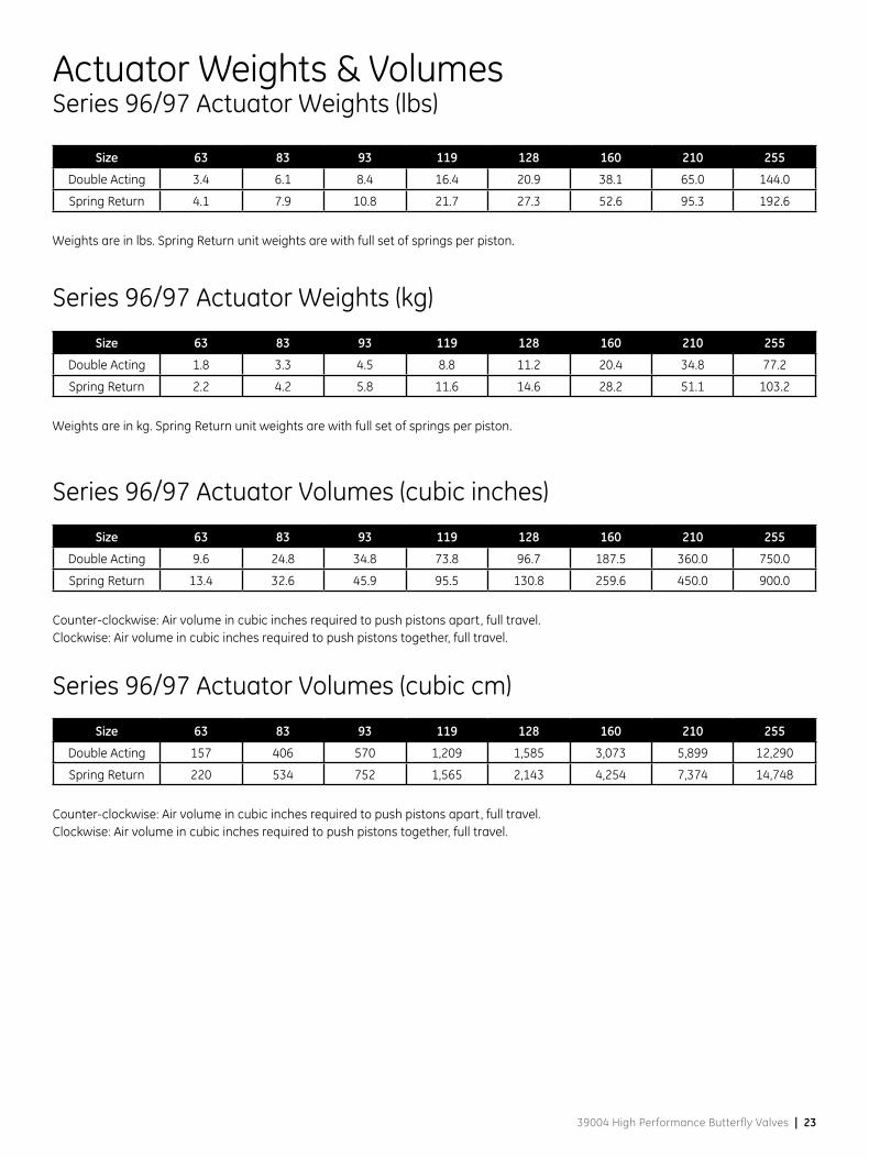
Actuator Weights & VolumesSeries 96/97 Actuator Weights (lbs)
Size 63 83 93 119 128 160 210 255
Double Acting 3.4 6.1 8.4 16.4 20.9 38.1 65.0 144.0
Spring Return 4.1 7.9 10.8 21.7 27.3 52.6 95.3 192.6
Weights are in lbs. Spring Return unit weights are with full set of springs per piston.
Series 96/97 Actuator Weights (kg)
Size 63 83 93 119 128 160 210 255
Double Acting 1.8 3.3 4.5 8.8 11.2 20.4 34.8 77.2
Spring Return 2.2 4.2 5.8 11.6 14.6 28.2 51.1 103.2
Weights are in kg. Spring Return unit weights are with full set of springs per piston.
Series 96/97 Actuator Volumes (cubic inches)
Size 63 83 93 119 128 160 210 255
Double Acting 9.6 24.8 34.8 73.8 96.7 187.5 360.0 750.0
Spring Return 13.4 32.6 45.9 95.5 130.8 259.6 450.0 900.0
Counter-clockwise: Air volume in cubic inches required to push pistons apart, full travel.Clockwise: Air volume in cubic inches required to push pistons together, full travel.
Series 96/97 Actuator Volumes (cubic cm)
Size 63 83 93 119 128 160 210 255
Double Acting 157 406 570 1,209 1,585 3,073 5,899 12,290
Spring Return 220 534 752 1,565 2,143 4,254 7,374 14,748
Counter-clockwise: Air volume in cubic inches required to push pistons apart, full travel.Clockwise: Air volume in cubic inches required to push pistons together, full travel.

24 | GE Oil & Gas

39004 High Performance Butterfly Valves | 25
Options and AccessoriesThe accessories below are available for mounting with the Series 39004 and Series 96/97 HPBV package. All positioners are available with standard NAMUR mounting.
Product Available Option
Digital Positioners
SVI AP
SVI II ESD
FVP® 110
Pneumatic Positioners4700P
4700E
Other Options
78 Series Airset
77 Series Lockup Valve
4411 I/P
496 Switches
Solenold Valves
Status Monitors
Consult Masoneilan for additional Options and Accessories.

26 | GE Oil & Gas
Notes

39004 High Performance Butterfly Valves | 27
Notes
DISTRIBUTOR
* Trademark of the General Electric Company.Other company names and product names used in this document arethe registered trademarks or trademarks of their respective owners.
© 2014 General Electric Company. All rights reserved.
Visit our web-site: www.fr-eps.com
E.P. & S. - FRANCE24 bis rue de Picpus75012 PARISTel: +33 (0) 762 682 291Tel: +33 (0) 650 590 [email protected]
E.P. & S. - CAMEROONImmeuble Carré d’OrRue Soppo Priso Côté Chococho, BonaprisoDOUALATel: +237 6 52 12 70 95Tel: +33 (0) 782 006 [email protected]