Masoneilan* 21000 Series - fr-eps.com 60534-4 and ANSI/FCI 70.2 Class Standard Bonnet Extension...
34
Technical Specifications 02/2016 Masoneilan* 21000 Series Complete Line of Rugged, Top Guided, Globe Valves with Lo-dB* and Anti-Cavitation Capabilities GE Oil & Gas
Transcript of Masoneilan* 21000 Series - fr-eps.com 60534-4 and ANSI/FCI 70.2 Class Standard Bonnet Extension...
Technical Specifications02/2016
Masoneilan* 21000 Series Complete Line of Rugged, Top Guided, Globe Valves with Lo-dB* and Anti-Cavitation Capabilities
GE Oil & Gas
2 | GE Oil & Gas © 2016 General Electric Company. All rights reserved.
Table of ContentsNumbering System ..........................................................................................................................................................................3
Ratings/Connections(1) ....................................................................................................................................................................5
Cv and FL versus Travel ...........................................................................................................................................................6-16
Materials of Construction ...................................................................................................................................................17-22
Bellows Seal Design Features 21000 BS Series ...............................................................................................................23
Materials of Construction ...................................................................................................................................................24-26
Dimensions (inches) ...............................................................................................................................................................27-28
Dimensions (mm) ....................................................................................................................................................................29-30
Weights ..............................................................................................................................................................................................31
Dimensions and Weights (in./lbs) ...........................................................................................................................................32
Dimensions and Weights (mm/kg) ........................................................................................................................................33
21000 Series Control Valves Technical Specifications | 3© 2016 General Electric Company. All rights reserved.
Flow Characteristics
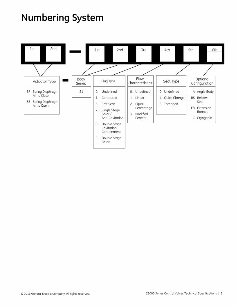
Optional Configuration
Numbering System
1st 2nd 5th4th3rd2nd1st 6th
Actuator Type
0. Undefined
1. Contoured
6. Soft Seat
7. Single Stage Lo-dB/ Anti-Cavitation
8. Double Stage Cavitation Containment
9. Double Stage Lo-dB
Plug TypeBody Series
21 A Angle Body
BS Bellows Seal
EB Extension Bonnet
C Cryogenic
0. Undefined
4. Quick Change
5. Threaded
Seat Type
0. Undefined
1. Linear
2. Equal Percentage
3. Modified Percent
87 Spring Diaphragm Air to Close
88 Spring Diaphragm Air to Open
4 | GE Oil & Gas © 2016 General Electric Company. All rights reserved.
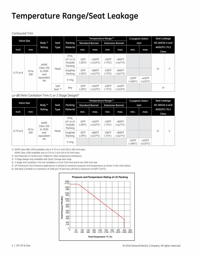
Temperature Range/Seat Leakage
Lo-dB*/Anti-Cavitation Trim (1 or 2 Stage Design)(3)
Contoured Trim
1) ASME Class 900-1500 available only in 0.75 to 4 inch (20 to 100 mm) sizes. ASME Class 2500 available only in 0.75 to 2 inch (20 to 50 mm) sizes.2) See Materials of Construction Tables for other temperature limitations.3) 2-Stage design only available with Quick Change seat rings.4) 2-Stage Anti-Cavitation Trim not available in 6 inch (150 mm) and 8 inch (200 mm) size.5) LE* Packing for low emissions applications is limited to maximum pressure and temperature as shown in the chart below.6) Soft seat is limited to a maximum of 1000 psi (70 bar) shut-off and a maximum of 450°F (232°C).
Pressure and Temperature Rating of LE Packing
Flu
id P
ress
ure
PS
I (B
ar)
Fluid Temperature °F (°C)
0 50 100 150 200 250 300 350 400 450 500 (10) (38) (66) (93) (121) (149) (177) (204) (232) (260)
1600(112)
1400(98)
1200(84)
1000(70)
800(56)
600(42)
400(28)
200(14)
0
Valve SizeBody (1)
Rating
Seat
Type
Packing
Material
Temperature Range (2) Cryogenic Exten-
sion
Seat Leakage
IEC 60534-4 and
ANSI/FCI 70.2
Class
Standard Bonnet Extension Bonnet
Inch mm min. max. min. max. min. max.
0.75 to 820 to 200
ASME Class 150 to 2500
and equivalent
PN
Metal
PTFE, LE* or LE FireSafe Packing
-20°F (-29°C)
+450°F (+232°C)
-100°F (-73°C)
+800°F (+427°C)
IV VGraphite Packing
-20°F (-29°C)
+800°F (+427°C)
-100°F (-73°C)
+800°F (+427°C)
V-ring-320°F
(-196°C)+450°F
(+232°C)
Soft Seat (6) Any
-20°F (-29°C)
+450°F (+232°C)
-100°F (-73°C)
+450°F (+232°C)
VI
Valve SizeBody (1)
Rating
Seat
Type
Packing
Material
Temperature Range (2) Cryogenic Exten-
sion
Seat Leakage
IEC 60534-4 and
ANSI/FCI 70.2
Class
Standard Bonnet Extension Bonnet
Inch mm min. max. min. max. min. max.
0.75 to 820 to 200
ASME Class 150 to 2500
and equivalent
PN
Metal
PTFE, LE* or LE FireSafe Packing
-20°F (-29°C)
+450°F (+232°C)
-100°F (-73°C)
+800°F (+427°C)
IV VGraphite Packing
-20°F (-29°C)
+800°F (+427°C)
-100°F (-73°C)
+800°F (+427°C)
V-ring-320°F
(-196°C)+450°F
(+232°C)
21000 Series Control Valves Technical Specifications | 5© 2016 General Electric Company. All rights reserved.
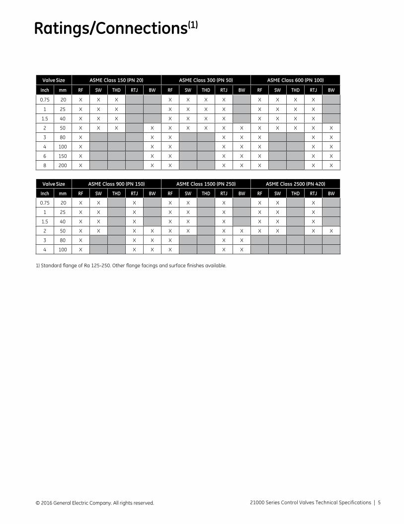
Valve Size ASME Class 900 (PN 150) ASME Class 1500 (PN 250) ASME Class 2500 (PN 420)
Inch mm RF SW THD RTJ BW RF SW THD RTJ BW RF SW THD RTJ BW
0.75 20 X X X X X X X X X
1 25 X X X X X X X X X
1.5 40 X X X X X X X X X
2 50 X X X X X X X X X X X X
3 80 X X X X X X
4 100 X X X X X X
Valve Size ASME Class 150 (PN 20) ASME Class 300 (PN 50) ASME Class 600 (PN 100)
Inch mm RF SW THD RTJ BW RF SW THD RTJ BW RF SW THD RTJ BW
0.75 20 X X X X X X X X X X X
1 25 X X X X X X X X X X X
1.5 40 X X X X X X X X X X X
2 50 X X X X X X X X X X X X X X
3 80 X X X X X X X X
4 100 X X X X X X X X
6 150 X X X X X X X X
8 200 X X X X X X X X
Ratings/Connections(1)
1) Standard flange of Ra 125-250. Other flange facings and surface finishes available.
6 | GE Oil & Gas
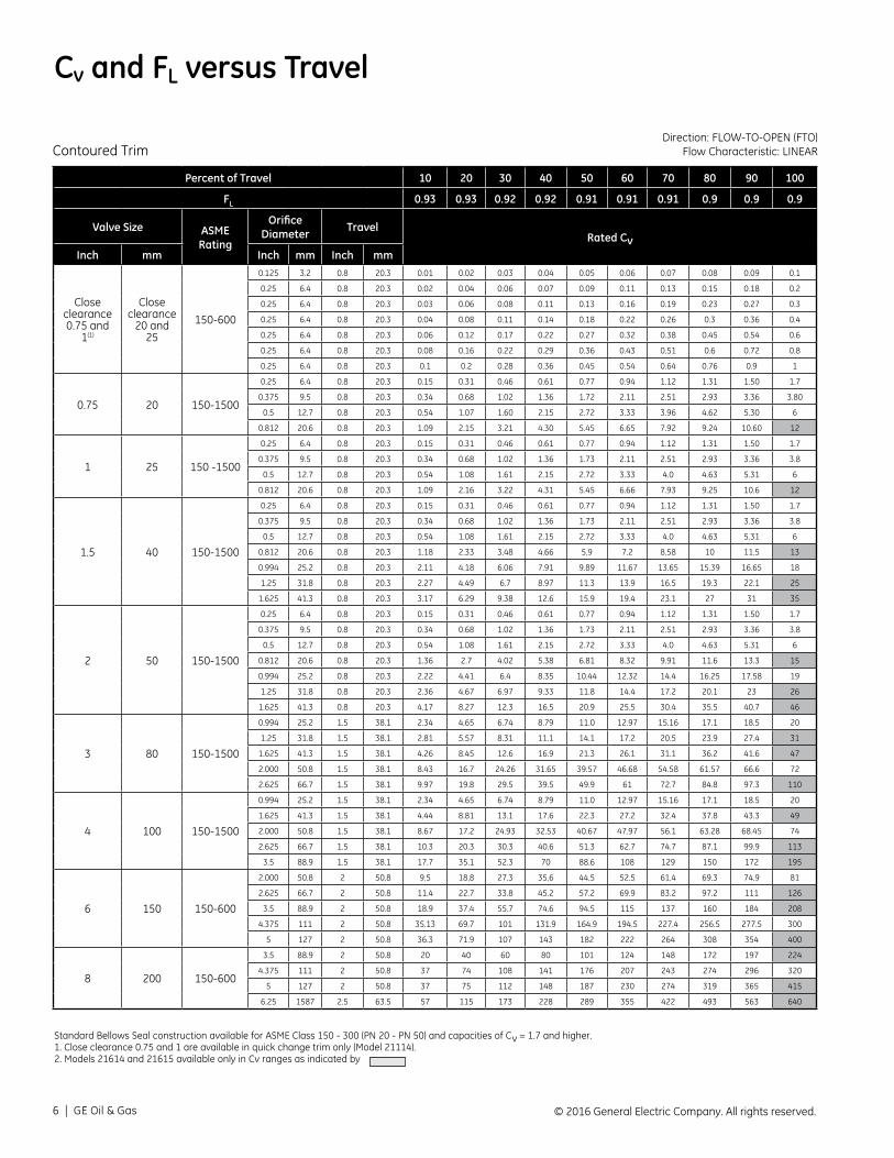
Cv and FL versus Travel
Direction: FLOW-TO-OPEN (FTO) Flow Characteristic: LINEARContoured Trim
Standard Bellows Seal construction available for ASME Class 150 - 300 (PN 20 - PN 50) and capacities of Cv = 1.7 and higher.1. Close clearance 0.75 and 1 are available in quick change trim only (Model 21114).2. Models 21614 and 21615 available only in Cv ranges as indicated by
Percent of Travel 10 20 30 40 50 60 70 80 90 100
FL 0.93 0.93 0.92 0.92 0.91 0.91 0.91 0.9 0.9 0.9
Valve Size ASME Rating
Orifice Diameter Travel
Rated CvInch mm Inch mm Inch mm
Close clearance 0.75 and
1(1)
Close clearance
20 and 25
150-600
0.125 3.2 0.8 20.3 0.01 0.02 0.03 0.04 0.05 0.06 0.07 0.08 0.09 0.1
0.25 6.4 0.8 20.3 0.02 0.04 0.06 0.07 0.09 0.11 0.13 0.15 0.18 0.2
0.25 6.4 0.8 20.3 0.03 0.06 0.08 0.11 0.13 0.16 0.19 0.23 0.27 0.3
0.25 6.4 0.8 20.3 0.04 0.08 0.11 0.14 0.18 0.22 0.26 0.3 0.36 0.4
0.25 6.4 0.8 20.3 0.06 0.12 0.17 0.22 0.27 0.32 0.38 0.45 0.54 0.6
0.25 6.4 0.8 20.3 0.08 0.16 0.22 0.29 0.36 0.43 0.51 0.6 0.72 0.8
0.25 6.4 0.8 20.3 0.1 0.2 0.28 0.36 0.45 0.54 0.64 0.76 0.9 1
0.75 20 150-1500
0.25 6.4 0.8 20.3 0.15 0.31 0.46 0.61 0.77 0.94 1.12 1.31 1.50 1.7
0.375 9.5 0.8 20.3 0.34 0.68 1.02 1.36 1.72 2.11 2.51 2.93 3.36 3.80
0.5 12.7 0.8 20.3 0.54 1.07 1.60 2.15 2.72 3.33 3.96 4.62 5.30 6
0.812 20.6 0.8 20.3 1.09 2.15 3.21 4.30 5.45 6.65 7.92 9.24 10.60 12
1 25 150 -1500
0.25 6.4 0.8 20.3 0.15 0.31 0.46 0.61 0.77 0.94 1.12 1.31 1.50 1.7
0.375 9.5 0.8 20.3 0.34 0.68 1.02 1.36 1.73 2.11 2.51 2.93 3.36 3.8
0.5 12.7 0.8 20.3 0.54 1.08 1.61 2.15 2.72 3.33 4.0 4.63 5.31 6
0.812 20.6 0.8 20.3 1.09 2.16 3.22 4.31 5.45 6.66 7.93 9.25 10.6 12
1.5 40 150-1500
0.25 6.4 0.8 20.3 0.15 0.31 0.46 0.61 0.77 0.94 1.12 1.31 1.50 1.7
0.375 9.5 0.8 20.3 0.34 0.68 1.02 1.36 1.73 2.11 2.51 2.93 3.36 3.8
0.5 12.7 0.8 20.3 0.54 1.08 1.61 2.15 2.72 3.33 4.0 4.63 5.31 6
0.812 20.6 0.8 20.3 1.18 2.33 3.48 4.66 5.9 7.2 8.58 10 11.5 13
0.994 25.2 0.8 20.3 2.11 4.18 6.06 7.91 9.89 11.67 13.65 15.39 16.65 18
1.25 31.8 0.8 20.3 2.27 4.49 6.7 8.97 11.3 13.9 16.5 19.3 22.1 25
1.625 41.3 0.8 20.3 3.17 6.29 9.38 12.6 15.9 19.4 23.1 27 31 35
2 50 150-1500
0.25 6.4 0.8 20.3 0.15 0.31 0.46 0.61 0.77 0.94 1.12 1.31 1.50 1.7
0.375 9.5 0.8 20.3 0.34 0.68 1.02 1.36 1.73 2.11 2.51 2.93 3.36 3.8
0.5 12.7 0.8 20.3 0.54 1.08 1.61 2.15 2.72 3.33 4.0 4.63 5.31 6
0.812 20.6 0.8 20.3 1.36 2.7 4.02 5.38 6.81 8.32 9.91 11.6 13.3 15
0.994 25.2 0.8 20.3 2.22 4.41 6.4 8.35 10.44 12.32 14.4 16.25 17.58 19
1.25 31.8 0.8 20.3 2.36 4.67 6.97 9.33 11.8 14.4 17.2 20.1 23 26
1.625 41.3 0.8 20.3 4.17 8.27 12.3 16.5 20.9 25.5 30.4 35.5 40.7 46
3 80 150-1500
0.994 25.2 1.5 38.1 2.34 4.65 6.74 8.79 11.0 12.97 15.16 17.1 18.5 20
1.25 31.8 1.5 38.1 2.81 5.57 8.31 11.1 14.1 17.2 20.5 23.9 27.4 31
1.625 41.3 1.5 38.1 4.26 8.45 12.6 16.9 21.3 26.1 31.1 36.2 41.6 47
2.000 50.8 1.5 38.1 8.43 16.7 24.26 31.65 39.57 46.68 54.58 61.57 66.6 72
2.625 66.7 1.5 38.1 9.97 19.8 29.5 39.5 49.9 61 72.7 84.8 97.3 110
4 100 150-1500
0.994 25.2 1.5 38.1 2.34 4.65 6.74 8.79 11.0 12.97 15.16 17.1 18.5 20
1.625 41.3 1.5 38.1 4.44 8.81 13.1 17.6 22.3 27.2 32.4 37.8 43.3 49
2.000 50.8 1.5 38.1 8.67 17.2 24.93 32.53 40.67 47.97 56.1 63.28 68.45 74
2.625 66.7 1.5 38.1 10.3 20.3 30.3 40.6 51.3 62.7 74.7 87.1 99.9 113
3.5 88.9 1.5 38.1 17.7 35.1 52.3 70 88.6 108 129 150 172 195
6 150 150-600
2.000 50.8 2 50.8 9.5 18.8 27.3 35.6 44.5 52.5 61.4 69.3 74.9 81
2.625 66.7 2 50.8 11.4 22.7 33.8 45.2 57.2 69.9 83.2 97.2 111 126
3.5 88.9 2 50.8 18.9 37.4 55.7 74.6 94.5 115 137 160 184 208
4.375 111 2 50.8 35.13 69.7 101 131.9 164.9 194.5 227.4 256.5 277.5 300
5 127 2 50.8 36.3 71.9 107 143 182 222 264 308 354 400
8 200 150-600
3.5 88.9 2 50.8 20 40 60 80 101 124 148 172 197 224
4.375 111 2 50.8 37 74 108 141 176 207 243 274 296 320
5 127 2 50.8 37 75 112 148 187 230 274 319 365 415
6.25 1587 2.5 63.5 57 115 173 228 289 355 422 493 563 640
© 2016 General Electric Company. All rights reserved.
21000 Series Control Valves Technical Specifications | 7© 2016 General Electric Company. All rights reserved.
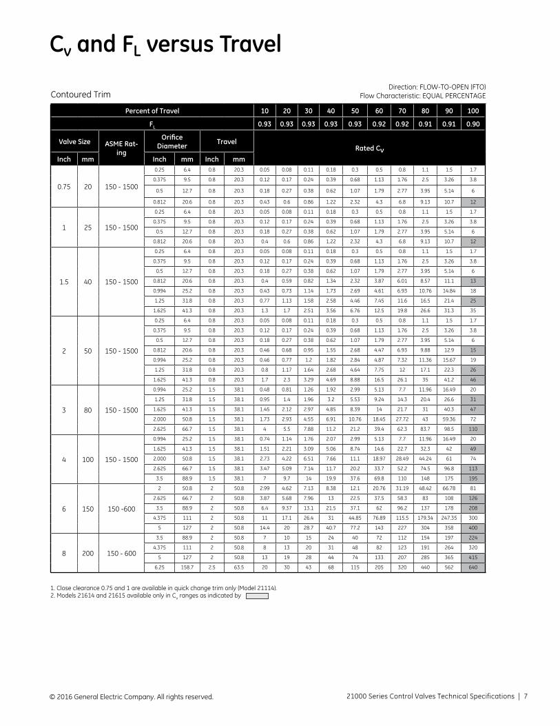
Cv and FL versus Travel
Contoured TrimDirection: FLOW-TO-OPEN (FTO)
Flow Characteristic: EQUAL PERCENTAGE
Percent of Travel 10 20 30 40 50 60 70 80 90 100
FL 0.93 0.93 0.93 0.93 0.93 0.92 0.92 0.91 0.91 0.90
Valve Size ASME Rat-ing
Orifice Diameter Travel
Rated CvInch mm Inch mm Inch mm
0.75 20 150 - 1500
0.25 6.4 0.8 20.3 0.05 0.08 0.11 0.18 0.3 0.5 0.8 1.1 1.5 1.7
0.375 9.5 0.8 20.3 0.12 0.17 0.24 0.39 0.68 1.13 1.76 2.5 3.26 3.8
0.5 12.7 0.8 20.3 0.18 0.27 0.38 0.62 1.07 1.79 2.77 3.95 5.14 6
0.812 20.6 0.8 20.3 0.43 0.6 0.86 1.22 2.32 4.3 6.8 9.13 10.7 12
1 25 150 - 1500
0.25 6.4 0.8 20.3 0.05 0.08 0.11 0.18 0.3 0.5 0.8 1.1 1.5 1.7
0.375 9.5 0.8 20.3 0.12 0.17 0.24 0.39 0.68 1.13 1.76 2.5 3.26 3.8
0.5 12.7 0.8 20.3 0.18 0.27 0.38 0.62 1.07 1.79 2.77 3.95 5.14 6
0.812 20.6 0.8 20.3 0.4 0.6 0.86 1.22 2.32 4.3 6.8 9.13 10.7 12
1.5 40 150 - 1500
0.25 6.4 0.8 20.3 0.05 0.08 0.11 0.18 0.3 0.5 0.8 1.1 1.5 1.7
0.375 9.5 0.8 20.3 0.12 0.17 0.24 0.39 0.68 1.13 1.76 2.5 3.26 3.8
0.5 12.7 0.8 20.3 0.18 0.27 0.38 0.62 1.07 1.79 2.77 3.95 5.14 6
0.812 20.6 0.8 20.3 0.4 0.59 0.82 1.34 2.32 3.87 6.01 8.57 11.1 13
0.994 25.2 0.8 20.3 0.43 0.73 1.14 1.73 2.69 4.61 6.93 10.76 14.84 18
1.25 31.8 0.8 20.3 0.77 1.13 1.58 2.58 4.46 7.45 11.6 16.5 21.4 25
1.625 41.3 0.8 20.3 1.3 1.7 2.51 3.56 6.76 12.5 19.8 26.6 31.3 35
2 50 150 - 1500
0.25 6.4 0.8 20.3 0.05 0.08 0.11 0.18 0.3 0.5 0.8 1.1 1.5 1.7
0.375 9.5 0.8 20.3 0.12 0.17 0.24 0.39 0.68 1.13 1.76 2.5 3.26 3.8
0.5 12.7 0.8 20.3 0.18 0.27 0.38 0.62 1.07 1.79 2.77 3.95 5.14 6
0.812 20.6 0.8 20.3 0.46 0.68 0.95 1.55 2.68 4.47 6.93 9.88 12.9 15
0.994 25.2 0.8 20.3 0.46 0.77 1.2 1.82 2.84 4.87 7.32 11.36 15.67 19
1.25 31.8 0.8 20.3 0.8 1.17 1.64 2.68 4.64 7.75 12 17.1 22.3 26
1.625 41.3 0.8 20.3 1.7 2.3 3.29 4.69 8.88 16.5 26.1 35 41.2 46
3 80 150 - 1500
0.994 25.2 1.5 38.1 0.48 0.81 1.26 1.92 2.99 5.13 7.7 11.96 16.49 20
1.25 31.8 1.5 38.1 0.95 1.4 1.96 3.2 5.53 9.24 14.3 20.4 26.6 31
1.625 41.3 1.5 38.1 1.45 2.12 2.97 4.85 8.39 14 21.7 31 40.3 47
2.000 50.8 1.5 38.1 1.73 2.93 4.55 6.91 10.76 18.45 27.72 43 59.36 72
2.625 66.7 1.5 38.1 4 5.5 7.88 11.2 21.2 39.4 62.3 83.7 98.5 110
4 100 150 - 1500
0.994 25.2 1.5 38.1 0.74 1.14 1.76 2.07 2.99 5.13 7.7 11.96 16.49 20
1.625 41.3 1.5 38.1 1.51 2.21 3.09 5.06 8.74 14.6 22.7 32.3 42 49
2.000 50.8 1.5 38.1 2.73 4.22 6.51 7.66 11.1 18.97 28.49 44.24 61 74
2.625 66.7 1.5 38.1 3.47 5.09 7.14 11.7 20.2 33.7 52.2 74.5 96.8 113
3.5 88.9 1.5 38.1 7 9.7 14 19.9 37.6 69.8 110 148 175 195
6 150 150 -600
2 50.8 2 50.8 2.99 4.62 7.13 8.38 12.1 20.76 31.19 48.42 66.78 81
2.625 66.7 2 50.8 3.87 5.68 7.96 13 22.5 37.5 58.3 83 108 126
3.5 88.9 2 50.8 6.4 9.37 13.1 21.5 37.1 62 96.2 137 178 208
4.375 111 2 50.8 11 17.1 26.4 31 44.85 76.89 115.5 179.34 247.35 300
5 127 2 50.8 14.4 20 28.7 40.7 77.2 143 227 304 358 400
8 200 150 - 600
3.5 88.9 2 50.8 7 10 15 24 40 72 112 154 197 224
4.375 111 2 50.8 8 13 20 31 48 82 123 191 264 320
5 127 2 50.8 13 19 28 44 74 133 207 285 365 415
6.25 158.7 2.5 63.5 20 30 43 68 115 205 320 440 562 640
1. Close clearance 0.75 and 1 are available in quick change trim only (Model 21114).2. Models 21614 and 21615 available only in Cv ranges as indicated by
8 | GE Oil & Gas © 2016 General Electric Company. All rights reserved.
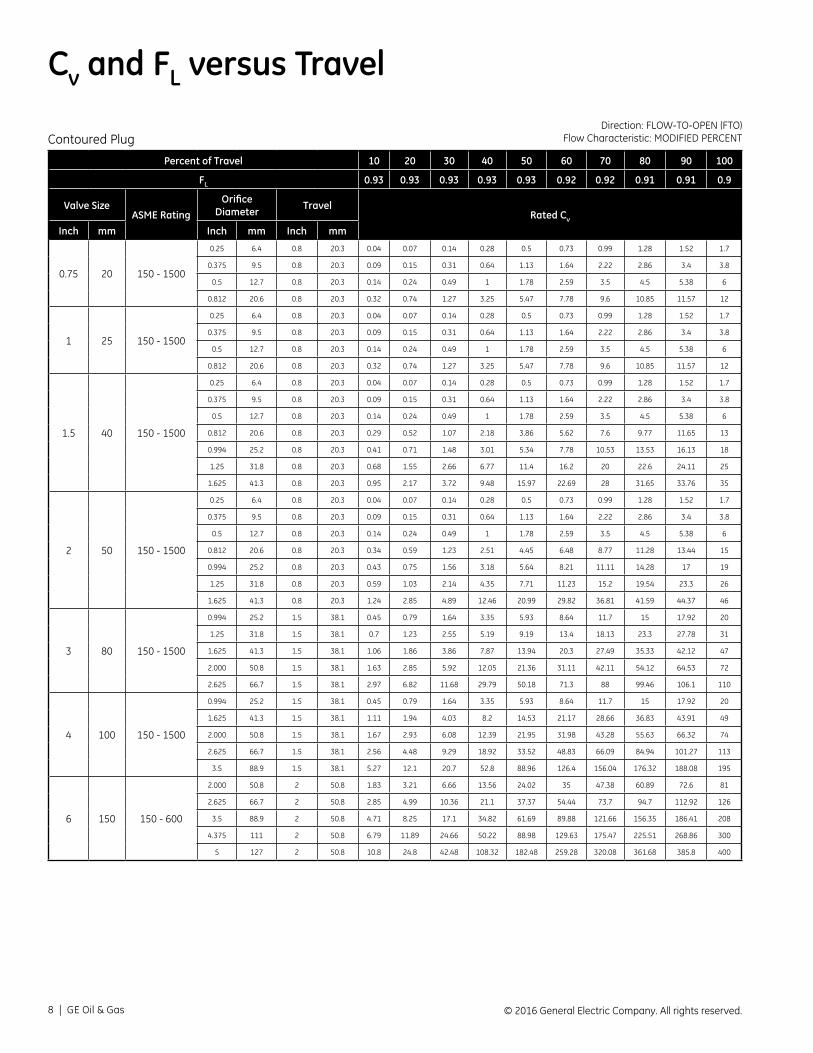
Percent of Travel 10 20 30 40 50 60 70 80 90 100
FL 0.93 0.93 0.93 0.93 0.93 0.92 0.92 0.91 0.91 0.9
Valve SizeASME Rating
Orifice Diameter Travel
Rated Cv
Inch mm Inch mm Inch mm
0.75 20 150 - 1500
0.25 6.4 0.8 20.3 0.04 0.07 0.14 0.28 0.5 0.73 0.99 1.28 1.52 1.7
0.375 9.5 0.8 20.3 0.09 0.15 0.31 0.64 1.13 1.64 2.22 2.86 3.4 3.8
0.5 12.7 0.8 20.3 0.14 0.24 0.49 1 1.78 2.59 3.5 4.5 5.38 6
0.812 20.6 0.8 20.3 0.32 0.74 1.27 3.25 5.47 7.78 9.6 10.85 11.57 12
1 25 150 - 1500
0.25 6.4 0.8 20.3 0.04 0.07 0.14 0.28 0.5 0.73 0.99 1.28 1.52 1.7
0.375 9.5 0.8 20.3 0.09 0.15 0.31 0.64 1.13 1.64 2.22 2.86 3.4 3.8
0.5 12.7 0.8 20.3 0.14 0.24 0.49 1 1.78 2.59 3.5 4.5 5.38 6
0.812 20.6 0.8 20.3 0.32 0.74 1.27 3.25 5.47 7.78 9.6 10.85 11.57 12
1.5 40 150 - 1500
0.25 6.4 0.8 20.3 0.04 0.07 0.14 0.28 0.5 0.73 0.99 1.28 1.52 1.7
0.375 9.5 0.8 20.3 0.09 0.15 0.31 0.64 1.13 1.64 2.22 2.86 3.4 3.8
0.5 12.7 0.8 20.3 0.14 0.24 0.49 1 1.78 2.59 3.5 4.5 5.38 6
0.812 20.6 0.8 20.3 0.29 0.52 1.07 2.18 3.86 5.62 7.6 9.77 11.65 13
0.994 25.2 0.8 20.3 0.41 0.71 1.48 3.01 5.34 7.78 10.53 13.53 16.13 18
1.25 31.8 0.8 20.3 0.68 1.55 2.66 6.77 11.4 16.2 20 22.6 24.11 25
1.625 41.3 0.8 20.3 0.95 2.17 3.72 9.48 15.97 22.69 28 31.65 33.76 35
2 50 150 - 1500
0.25 6.4 0.8 20.3 0.04 0.07 0.14 0.28 0.5 0.73 0.99 1.28 1.52 1.7
0.375 9.5 0.8 20.3 0.09 0.15 0.31 0.64 1.13 1.64 2.22 2.86 3.4 3.8
0.5 12.7 0.8 20.3 0.14 0.24 0.49 1 1.78 2.59 3.5 4.5 5.38 6
0.812 20.6 0.8 20.3 0.34 0.59 1.23 2.51 4.45 6.48 8.77 11.28 13.44 15
0.994 25.2 0.8 20.3 0.43 0.75 1.56 3.18 5.64 8.21 11.11 14.28 17 19
1.25 31.8 0.8 20.3 0.59 1.03 2.14 4.35 7.71 11.23 15.2 19.54 23.3 26
1.625 41.3 0.8 20.3 1.24 2.85 4.89 12.46 20.99 29.82 36.81 41.59 44.37 46
3 80 150 - 1500
0.994 25.2 1.5 38.1 0.45 0.79 1.64 3.35 5.93 8.64 11.7 15 17.92 20
1.25 31.8 1.5 38.1 0.7 1.23 2.55 5.19 9.19 13.4 18.13 23.3 27.78 31
1.625 41.3 1.5 38.1 1.06 1.86 3.86 7.87 13.94 20.3 27.49 35.33 42.12 47
2.000 50.8 1.5 38.1 1.63 2.85 5.92 12.05 21.36 31.11 42.11 54.12 64.53 72
2.625 66.7 1.5 38.1 2.97 6.82 11.68 29.79 50.18 71.3 88 99.46 106.1 110
4 100 150 - 1500
0.994 25.2 1.5 38.1 0.45 0.79 1.64 3.35 5.93 8.64 11.7 15 17.92 20
1.625 41.3 1.5 38.1 1.11 1.94 4.03 8.2 14.53 21.17 28.66 36.83 43.91 49
2.000 50.8 1.5 38.1 1.67 2.93 6.08 12.39 21.95 31.98 43.28 55.63 66.32 74
2.625 66.7 1.5 38.1 2.56 4.48 9.29 18.92 33.52 48.83 66.09 84.94 101.27 113
3.5 88.9 1.5 38.1 5.27 12.1 20.7 52.8 88.96 126.4 156.04 176.32 188.08 195
6 150 150 - 600
2.000 50.8 2 50.8 1.83 3.21 6.66 13.56 24.02 35 47.38 60.89 72.6 81
2.625 66.7 2 50.8 2.85 4.99 10.36 21.1 37.37 54.44 73.7 94.7 112.92 126
3.5 88.9 2 50.8 4.71 8.25 17.1 34.82 61.69 89.88 121.66 156.35 186.41 208
4.375 111 2 50.8 6.79 11.89 24.66 50.22 88.98 129.63 175.47 225.51 268.86 300
5 127 2 50.8 10.8 24.8 42.48 108.32 182.48 259.28 320.08 361.68 385.8 400
Cv and FL versus Travel
Direction: FLOW-TO-OPEN (FTO) Flow Characteristic: MODIFIED PERCENTContoured Plug
21000 Series Control Valves Technical Specifications | 9© 2016 General Electric Company. All rights reserved.
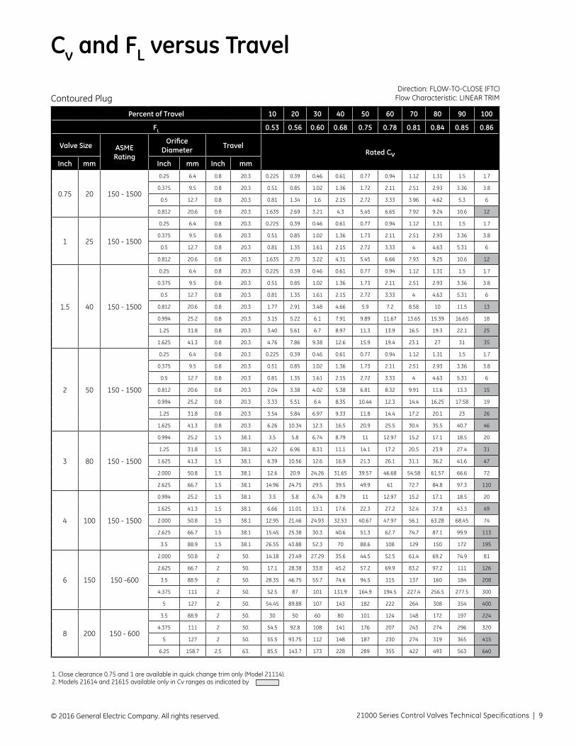
Cv and FL versus Travel
Direction: FLOW-TO-CLOSE (FTC) Flow Characteristic: LINEAR TRIMContoured Plug
Percent of Travel 10 20 30 40 50 60 70 80 90 100
FL 0.53 0.56 0.60 0.68 0.75 0.78 0.81 0.84 0.85 0.86
Valve Size ASME Rating
Orifice Diameter Travel
Rated CvInch mm Inch mm Inch mm
0.75 20 150 - 1500
0.25 6.4 0.8 20.3 0.225 0.39 0.46 0.61 0.77 0.94 1.12 1.31 1.5 1.7
0.375 9.5 0.8 20.3 0.51 0.85 1.02 1.36 1.72 2.11 2.51 2.93 3.36 3.8
0.5 12.7 0.8 20.3 0.81 1.34 1.6 2.15 2.72 3.33 3.96 4.62 5.3 6
0.812 20.6 0.8 20.3 1.635 2.69 3.21 4.3 5.45 6.65 7.92 9.24 10.6 12
1 25 150 - 1500
0.25 6.4 0.8 20.3 0.225 0.39 0.46 0.61 0.77 0.94 1.12 1.31 1.5 1.7
0.375 9.5 0.8 20.3 0.51 0.85 1.02 1.36 1.73 2.11 2.51 2.93 3.36 3.8
0.5 12.7 0.8 20.3 0.81 1.35 1.61 2.15 2.72 3.33 4 4.63 5.31 6
0.812 20.6 0.8 20.3 1.635 2.70 3.22 4.31 5.45 6.66 7.93 9.25 10.6 12
1.5 40 150 - 1500
0.25 6.4 0.8 20.3 0.225 0.39 0.46 0.61 0.77 0.94 1.12 1.31 1.5 1.7
0.375 9.5 0.8 20.3 0.51 0.85 1.02 1.36 1.73 2.11 2.51 2.93 3.36 3.8
0.5 12.7 0.8 20.3 0.81 1.35 1.61 2.15 2.72 3.33 4 4.63 5.31 6
0.812 20.6 0.8 20.3 1.77 2.91 3.48 4.66 5.9 7.2 8.58 10 11.5 13
0.994 25.2 0.8 20.3 3.15 5.22 6.1 7.91 9.89 11.67 13.65 15.39 16.65 18
1.25 31.8 0.8 20.3 3.40 5.61 6.7 8.97 11.3 13.9 16.5 19.3 22.1 25
1.625 41.3 0.8 20.3 4.76 7.86 9.38 12.6 15.9 19.4 23.1 27 31 35
2 50 150 - 1500
0.25 6.4 0.8 20.3 0.225 0.39 0.46 0.61 0.77 0.94 1.12 1.31 1.5 1.7
0.375 9.5 0.8 20.3 0.51 0.85 1.02 1.36 1.73 2.11 2.51 2.93 3.36 3.8
0.5 12.7 0.8 20.3 0.81 1.35 1.61 2.15 2.72 3.33 4 4.63 5.31 6
0.812 20.6 0.8 20.3 2.04 3.38 4.02 5.38 6.81 8.32 9.91 11.6 13.3 15
0.994 25.2 0.8 20.3 3.33 5.51 6.4 8.35 10.44 12.3 14.4 16.25 17.58 19
1.25 31.8 0.8 20.3 3.54 5.84 6.97 9.33 11.8 14.4 17.2 20.1 23 26
1.625 41.3 0.8 20.3 6.26 10.34 12.3 16.5 20.9 25.5 30.4 35.5 40.7 46
3 80 150 - 1500
0.994 25.2 1.5 38.1 3.5 5.8 6.74 8.79 11 12.97 15.2 17.1 18.5 20
1.25 31.8 1.5 38.1 4.22 6.96 8.31 11.1 14.1 17.2 20.5 23.9 27.4 31
1.625 41.3 1.5 38.1 6.39 10.56 12.6 16.9 21.3 26.1 31.1 36.2 41.6 47
2.000 50.8 1.5 38.1 12.6 20.9 24.26 31.65 39.57 46.68 54.58 61.57 66.6 72
2.625 66.7 1.5 38.1 14.96 24.75 29.5 39.5 49.9 61 72.7 84.8 97.3 110
4 100 150 - 1500
0.994 25.2 1.5 38.1 3.5 5.8 6.74 8.79 11 12.97 15.2 17.1 18.5 20
1.625 41.3 1.5 38.1 6.66 11.01 13.1 17.6 22.3 27.2 32.4 37.8 43.3 49
2.000 50.8 1.5 38.1 12.95 21.46 24.93 32.53 40.67 47.97 56.1 63.28 68.45 74
2.625 66.7 1.5 38.1 15.45 25.38 30.3 40.6 51.3 62.7 74.7 87.1 99.9 113
3.5 88.9 1.5 38.1 26.55 43.88 52.3 70 88.6 108 129 150 172 195
6 150 150 -600
2.000 50.8 2 50. 14.18 23.49 27.29 35.6 44.5 52.5 61.4 69.2 74.9 81
2.625 66.7 2 50. 17.1 28.38 33.8 45.2 57.2 69.9 83.2 97.2 111 126
3.5 88.9 2 50. 28.35 46.75 55.7 74.6 94.5 115 137 160 184 208
4.375 111 2 50. 52.5 87 101 131.9 164.9 194.5 227.4 256.5 277.5 300
5 127 2 50. 54.45 89.88 107 143 182 222 264 308 354 400
8 200 150 - 600
3.5 88.9 2 50. 30 50 60 80 101 124 148 172 197 224
4.375 111 2 50. 54.5 92.8 108 141 176 207 243 274 296 320
5 127 2 50. 55.5 93.75 112 148 187 230 274 319 365 415
6.25 158.7 2.5 63. 85.5 143.7 173 228 289 355 422 493 563 640
1. Close clearance 0.75 and 1 are available in quick change trim only (Model 21114).2. Models 21614 and 21615 available only in Cv ranges as indicated by
10 | GE Oil & Gas © 2016 General Electric Company. All rights reserved.
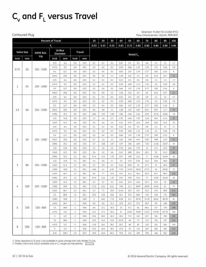
Cv and FL versus Travel
Direction: FLOW-TO-CLOSE (FTC) Flow Characteristic: EQUAL PERCENTContoured Plug
Percent of Travel 10 20 30 40 50 60 70 80 90 100
FL 0.53 0.53 0.55 0.63 0.72 0.80 0.80 0.80 0.80 0.80
Valve Size ASME Rat-ing
Orifice Diameter Travel
Rated Cv
Inch mm Inch mm Inch mm
0.75 20 150 - 1500
0.25 6.4 0.8 20.3 0.1 0.1 0.2 0.22 0.3 0.5 0.8 1.1 1.5 1.7
0.375 9.5 0.8 20.3 0.2 0.2 0.3 0.39 0.68 1.13 1.76 2.5 3.26 3.8
0.5 12.7 0.8 20.3 0.3 0.4 0.5 0.64 1.07 1.79 2.77 3.95 5.14 6
0.812 20.6 0.8 20.3 0.6 0.8 1.2 1.48 2.32 4.3 6.8 9.13 10.7 12
1 25 150 - 1500
0.25 6.4 0.8 20.3 0.1 0.1 0.2 0.22 0.3 0.5 0.8 1.1 1.5 1.7
0.375 9.5 0.8 20.3 0.2 0.2 0.3 0.39 0.68 1.13 1.76 2.5 3.26 3.8
0.5 12.7 0.8 20.3 0.3 0.4 0.5 0.64 1.07 1.79 2.77 3.95 5.14 6
0.812 20.6 0.8 20.3 0.6 0.8 1.2 1.48 2.32 4.3 6.8 9.13 10.7 12
1.5 40 150 - 1500
0.25 6.4 0.8 20.3 0.1 0.1 0.2 0.22 0.3 0.5 0.8 1.1 1.5 1.7
0.375 9.5 0.8 20.3 0.2 0.2 0.3 0.39 0.68 1.13 1.76 2.5 3.26 3.8
0.5 12.7 0.8 20.3 0.3 0.4 0.5 0.64 1.07 1.79 2.77 3.95 5.14 6
0.812 20.6 0.8 20.3 0.6 0.8 1.1 1.48 2.32 3.87 6.01 8.57 11.1 13
0.994 25.2 0.8 20.3 0.66 1.03 1.58 1.86 2.69 4.61 6.93 10.76 14.84 18
1.25 31.8 0.8 20.3 1.2 1.6 2.2 2.76 4.46 7.45 11.6 16.5 21.4 25
1.625 41.3 0.8 20.3 2.0 2.4 3.5 4.31 6.76 12.5 19.8 26.6 31.3 35
2 50 150 - 1500
0.25 6.4 0.8 20.3 0.1 0.1 0.2 0.22 0.3 0.5 0.8 1.1 1.5 1.7
0.375 9.5 0.8 20.3 0.2 0.2 0.3 0.39 0.68 1.13 1.76 2.5 3.26 3.8
0.5 12.7 0.8 20.3 0.3 0.4 0.5 0.64 1.07 1.79 2.77 3.95 5.14 6
0.812 20.6 0.8 20.3 0.7 1.0 1.3 1.64 2.68 4.47 6.93 9.88 12.9 15
0.994 25.2 0.8 20.3 0.7 1.08 1.67 1.97 2.84 4.87 7.32 11.36 15.67 19
1.25 31.8 0.8 20.3 1.2 1.6 2.3 2.76 4.64 7.75 12 17.1 22.3 26
1.625 41.3 0.8 20.3 2.6 3.2 4.6 5.67 8.88 16.5 26.1 35 41.2 46
3 80 150 - 1500
0.994 25.2 1.5 38.1 0.74 1.14 1.76 2.07 2.99 5.13 7.7 11.96 16.49 20
1.25 31.8 1.5 38.1 1.4 2.0 2.7 3.4 5.53 9.24 14.3 20.4 26.6 31
1.625 41.3 1.5 38.1 2.2 3.0 4.2 5.24 8.39 14 21.7 31 40.3 47
2.000 50.8 1.5 38.1 2.66 4.1 6.34 7.45 10.76 18.45 27.72 43 59.36 72
2.625 66.7 1.5 38.1 6.0 7.7 11.0 13.5 21.2 39.4 62.3 83.7 98.5 110
4 100 150 - 1500
0.994 25.2 1.5 38.1 0.74 1.14 1.76 2.07 2.99 5.13 7.7 11.96 16.49 20
1.625 41.3 1.5 38.1 2.3 3.1 4.3 5.41 8.74 14.6 22.7 32.3 42 49
2.000 50.8 1.5 38.1 2.73 4.22 6.51 7.66 11.1 18.97 28.49 44.24 61 74
2.625 66.7 1.5 38.1 5.2 7.1 10.0 12.55 20.2 33.7 52.2 74.5 96.8 113
3.5 88.9 1.5 38.1 10.5 13.6 19.6 24.1 37.6 69.8 110 148 175 195
6 150 150 - 600
2.000 50.8 2 50.8 3 4.62 7.13 8.38 12.1 20.76 31.19 48.42 66.78 81
2.625 66.7 2 50.8 5.8 8.0 11.1 13.9 22.5 37.5 58.3 83 108 126
3.5 88.9 2 50.8 9.6 13.1 18.3 23 37.1 62 96.2 137 178 208
4.375 111 2 50.8 11.1 17.1 26.4 31 44.85 76.89 115.5 179.34 247.35 300
5 127 2 50.8 21.6 28.0 40.2 49.4 77.2 143 227 304 358 400
8 200 150 - 600
3.5 88.9 2 50.8 10.5 14.0 21.0 25.75 40 72 112 154 197 224
4.375 111 2 50.8 11.8 18.2 28.2 33.1 48 82 123 191 264 320
5 127 2 50.8 19.5 26.6 39.2 47.9 74 133 207 285 365 415
6.25 158.7 2.5 63.5 30.0 42.0 60.2 73.9 115 205 320 440 562 640
1. Close clearance 0.75 and 1 are available in quick change trim only (Model 21114).2. Models 21614 and 21615 available only in Cv ranges as indicated by
21000 Series Control Valves Technical Specifications | 11© 2016 General Electric Company. All rights reserved.
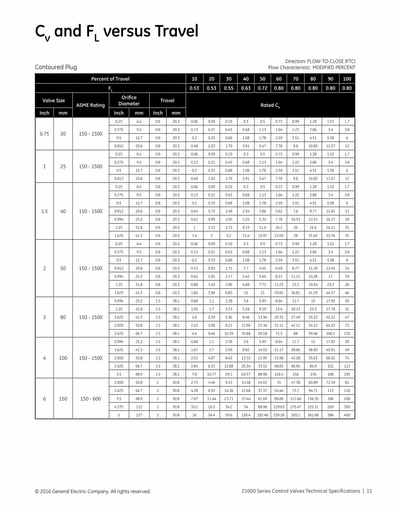
Cv and FL versus Travel
Direction: FLOW-TO-CLOSE (FTC) Flow Characteristic: MODIFIED PERCENTContoured Plug
Percent of Travel 10 20 30 40 50 60 70 80 90 100
FL 0.53 0.53 0.55 0.63 0.72 0.80 0.80 0.80 0.80 0.80
Valve SizeASME Rating
Orifice Diameter Travel
Rated Cv
Inch mm Inch mm Inch mm
0.75 20 150 - 1500
0.25 6.4 0.8 20.3 0.06 0.09 0.19 0.3 0.5 0.73 0.99 1.28 1.52 1.7
0.375 9.5 0.8 20.3 0.13 0.21 0.43 0.68 1.13 1.64 2.22 2.86 3.4 3.8
0.5 12.7 0.8 20.3 0.2 0.33 0.68 1.08 1.78 2.59 3.51 4.51 5.38 6
0.812 20.6 0.8 20.3 0.48 1.03 1.79 3.91 5.47 7.78 9.6 10.85 11.57 12
1 25 150 - 1500
0.25 6.4 0.8 20.3 0.06 0.09 0.19 0.3 0.5 0.73 0.99 1.28 1.52 1.7
0.375 9.5 0.8 20.3 0.13 0.21 0.43 0.68 1.13 1.64 2.22 2.86 3.4 3.8
0.5 12.7 0.8 20.3 0.2 0.33 0.68 1.08 1.78 2.59 3.51 4.51 5.38 6
0.812 20.6 0.8 20.3 0.48 1.03 1.79 3.91 5.47 7.78 9.6 10.85 11.57 12
1.5 40 150 - 1500
0.25 6.4 0.8 20.3 0.06 0.09 0.19 0.3 0.5 0.73 0.99 1.28 1.52 1.7
0.375 9.5 0.8 20.3 0.13 0.21 0.43 0.68 1.13 1.64 2.22 2.86 3.4 3.8
0.5 12.7 0.8 20.3 0.2 0.33 0.68 1.08 1.78 2.59 3.51 4.51 5.38 6
0.812 20.6 0.8 20.3 0.44 0.72 1.48 2.34 3.86 5.62 7.6 9.77 11.65 13
0.994 25.2 0.8 20.3 0.61 0.99 2.05 3.24 5.34 7.78 10.53 13.53 16.13 18
1.25 31.8 0.8 20.3 1 2.15 3.73 8.15 11.4 16.2 20 22.6 24.11 25
1.625 41.3 0.8 20.3 1.4 3 5.2 11.4 15.97 22.69 28 31.65 33.76 35
2 50 150 - 1500
0.25 6.4 0.8 20.3 0.06 0.09 0.19 0.3 0.5 0.73 0.99 1.28 1.52 1.7
0.375 9.5 0.8 20.3 0.13 0.21 0.43 0.68 1.13 1.64 2.22 2.86 3.4 3.8
0.5 12.7 0.8 20.3 0.2 0.33 0.68 1.08 1.78 2.59 3.51 4.51 5.38 6
0.812 20.6 0.8 20.3 0.51 0.83 1.71 2.7 4.45 6.48 8.77 11.28 13.44 15
0.994 25.2 0.8 20.3 0.65 1.05 2.17 3.42 5.64 8.21 11.11 14.28 17 19
1.25 31.8 0.8 20.3 0.88 1.43 2.96 4.68 7.71 11.23 15.2 19.54 23.3 26
1.625 41.3 0.8 20.3 1.84 3.96 6.85 15 21 29.82 36.81 41.59 44.37 46
3 80 150 - 1500
0.994 25.2 1.5 38.1 0.68 1.1 2.28 3.6 5.93 8.64 11.7 15 17.92 20
1.25 31.8 1.5 38.1 1.05 1.7 3.53 5.58 9.19 13.4 18.13 23.3 27.78 31
1.625 41.3 1.5 38.1 1.6 2.59 5.36 8.46 13.94 20.31 27.49 35.33 42.12 47
2.000 50.8 1.5 38.1 2.45 3.96 8.21 12.96 21.36 31.11 42.11 54.12 64.53 72
2.625 66.7 1.5 38.1 4.4 9.46 16.39 35.86 50.18 71.3 88 99.46 106.1 110
4 100 150 - 1500
0.994 25.2 1.5 38.1 0.68 1.1 2.28 3.6 5.93 8.64 11.7 15 17.92 20
1.625 41.3 1.5 38.1 1.67 2.7 5.59 8.82 14.53 21.17 28.66 36.83 43.91 49
2.000 50.8 1.5 38.1 2.52 4.07 8.43 13.32 21.95 31.98 43.28 55.63 66.32 74
2.625 66.7 1.5 38.1 3.84 6.22 12.88 20.34 33.52 48.83 66.94 84.9 101 113
3.5 88.9 1.5 38.1 7.8 16.77 29.1 63.57 88.96 126.4 156 176 188 195
6 150 150 - 600
2.000 50.8 2 50.8 2.75 4.46 9.23 14.58 24.02 35 47.38 60.89 72.59 81
2.625 66.7 2 50.8 4.28 6.93 14.36 22.68 37.37 54.44 73.7 94.71 113 126
3.5 88.9 2 50.8 7.07 11.44 23.71 37.44 61.69 89.88 121.66 156.35 186 208
4.375 111 2 50.8 10.2 16.5 34.2 54 88.98 129.63 175.47 225.51 269 300
5 127 2 50.8 16 34.4 59.6 130.4 182.48 259.28 320.1 361.68 386 400

12 | GE Oil & Gas © 2016 General Electric Company. All rights reserved.
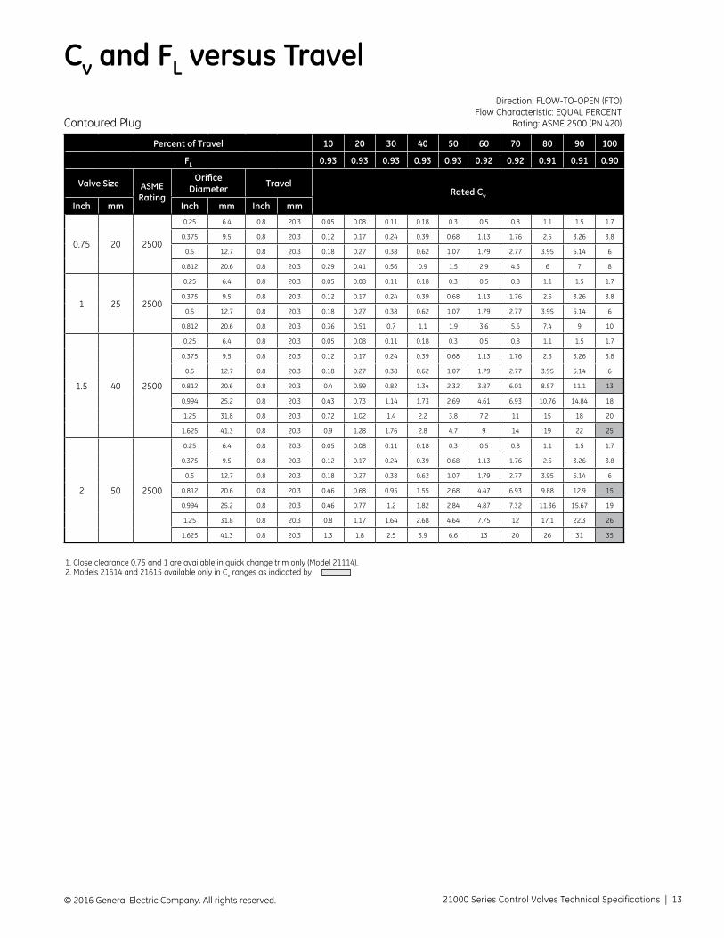
Cv and FL versus Travel
Contoured Plug
Direction: FLOW-TO-OPEN (FTO) Flow Characteristic: LINEARRating: ASME 2500 (PN 420)
Percent of Travel 10 20 30 40 50 60 70 80 90 100
FL 0.93 0.93 0.92 0.92 0.91 0.91 0.91 0.9 0.9 0.90
Valve Size ASME Rating
Orifice Diameter Travel
Rated Cv
Inch mm Inch mm Inch mm
0.75 20 2500
0.25 6.4 0.8 20.3 0.15 0.31 0.46 0.61 0.77 0.94 1.12 1.31 1.5 1.7
0.375 9.5 0.8 20.3 0.34 0.68 1.02 1.36 1.7 2.11 2.5 2.9 3.4 3.8
0.5 12.7 0.8 20.3 0.54 1.07 1.60 2.2 2.7 3.33 4 4.6 5.30 6
0.812 20.6 0.8 20.3 0.70 1.40 2.20 2.80 3.60 4.40 5.30 6.20 7.00 8
1 25 2500
0.25 6.4 0.8 20.3 0.15 0.31 0.46 0.61 0.77 0.94 1.12 1.31 1.50 1.7
0.375 9.5 0.8 20.3 0.34 0.68 1.02 1.36 1.73 2.11 2.5 2.9 3.4 3.8
0.5 12.7 0.8 20.3 0.54 1.08 1.61 2.2 2.7 3.33 4.0 4.6 5.3 6
0.812 20.6 0.8 20.3 0.9 1.8 2.7 3.6 4.5 5.6 6.6 7.7 9 10
1.5 40 2500
0.25 6.4 0.8 20.3 0.15 0.31 0.46 0.61 0.77 0.94 1.12 1.31 1.50 1.7
0.375 9.5 0.8 20.3 0.34 0.68 1.02 1.36 1.7 2.11 2.5 2.93 3.4 3.8
0.5 12.7 0.8 20.3 0.54 1.08 1.61 2.15 2.7 3.33 4.0 4.6 5.3 6
0.812 20.6 0.8 20.3 1.18 2.3 3.5 4.7 5.9 7.2 8.6 10 11.5 13
0.994 25.2 0.8 20.3 2.1 4.2 6.1 7.9 9.9 11.7 13.7 15.4 16.7 18
1.25 31.8 0.8 20.3 2.3 4.5 6.7 9.0 11.3 13.9 16.5 19.3 22.1 25
1.625 41.3 0.8 20.3 3.2 6.3 9.4 12.6 15.9 19.4 23.1 27 31 35
2 50 2500
0.25 6.4 0.8 20.3 0.15 0.31 0.46 0.61 0.77 0.94 1.12 1.31 1.50 1.7
0.375 9.5 0.8 20.3 0.34 0.68 1.02 1.36 1.7 2.11 2.5 2.9 3.4 3.8
0.5 12.7 0.8 20.3 0.54 1.08 1.61 2.2 2.7 3.33 4.0 4.6 5.3 6
0.812 20.6 0.8 20.3 1.4 2.7 4.0 5.4 6.8 8.3 9.9 11.6 13.3 15
0.994 25.2 0.8 20.3 2.2 4.4 6.4 8.4 10.4 12.3 14.4 16.3 17.6 19
1.25 31.8 0.8 20.3 2.4 4.7 7.0 9.3 11.8 14.4 17.2 20.1 23 26
1.625 41.3 0.8 20.3 3.2 6.3 9 12 16 19 23 27 31 35
1. Close clearance 0.75 and 1 are available in quick change trim only (Model 21114).2. Models 21614 and 21615 available only in Cv ranges as indicated by
21000 Series Control Valves Technical Specifications | 13© 2016 General Electric Company. All rights reserved.
Direction: FLOW-TO-OPEN (FTO) Flow Characteristic: EQUAL PERCENT
Rating: ASME 2500 (PN 420)
Percent of Travel 10 20 30 40 50 60 70 80 90 100
FL 0.93 0.93 0.93 0.93 0.93 0.92 0.92 0.91 0.91 0.90
Valve Size ASME Rating
Orifice Diameter Travel
Rated Cv
Inch mm Inch mm Inch mm
0.75 20 2500
0.25 6.4 0.8 20.3 0.05 0.08 0.11 0.18 0.3 0.5 0.8 1.1 1.5 1.7
0.375 9.5 0.8 20.3 0.12 0.17 0.24 0.39 0.68 1.13 1.76 2.5 3.26 3.8
0.5 12.7 0.8 20.3 0.18 0.27 0.38 0.62 1.07 1.79 2.77 3.95 5.14 6
0.812 20.6 0.8 20.3 0.29 0.41 0.56 0.9 1.5 2.9 4.5 6 7 8
1 25 2500
0.25 6.4 0.8 20.3 0.05 0.08 0.11 0.18 0.3 0.5 0.8 1.1 1.5 1.7
0.375 9.5 0.8 20.3 0.12 0.17 0.24 0.39 0.68 1.13 1.76 2.5 3.26 3.8
0.5 12.7 0.8 20.3 0.18 0.27 0.38 0.62 1.07 1.79 2.77 3.95 5.14 6
0.812 20.6 0.8 20.3 0.36 0.51 0.7 1.1 1.9 3.6 5.6 7.4 9 10
1.5 40 2500
0.25 6.4 0.8 20.3 0.05 0.08 0.11 0.18 0.3 0.5 0.8 1.1 1.5 1.7
0.375 9.5 0.8 20.3 0.12 0.17 0.24 0.39 0.68 1.13 1.76 2.5 3.26 3.8
0.5 12.7 0.8 20.3 0.18 0.27 0.38 0.62 1.07 1.79 2.77 3.95 5.14 6
0.812 20.6 0.8 20.3 0.4 0.59 0.82 1.34 2.32 3.87 6.01 8.57 11.1 13
0.994 25.2 0.8 20.3 0.43 0.73 1.14 1.73 2.69 4.61 6.93 10.76 14.84 18
1.25 31.8 0.8 20.3 0.72 1.02 1.4 2.2 3.8 7.2 11 15 18 20
1.625 41.3 0.8 20.3 0.9 1.28 1.76 2.8 4.7 9 14 19 22 25
2 50 2500
0.25 6.4 0.8 20.3 0.05 0.08 0.11 0.18 0.3 0.5 0.8 1.1 1.5 1.7
0.375 9.5 0.8 20.3 0.12 0.17 0.24 0.39 0.68 1.13 1.76 2.5 3.26 3.8
0.5 12.7 0.8 20.3 0.18 0.27 0.38 0.62 1.07 1.79 2.77 3.95 5.14 6
0.812 20.6 0.8 20.3 0.46 0.68 0.95 1.55 2.68 4.47 6.93 9.88 12.9 15
0.994 25.2 0.8 20.3 0.46 0.77 1.2 1.82 2.84 4.87 7.32 11.36 15.67 19
1.25 31.8 0.8 20.3 0.8 1.17 1.64 2.68 4.64 7.75 12 17.1 22.3 26
1.625 41.3 0.8 20.3 1.3 1.8 2.5 3.9 6.6 13 20 26 31 35
Contoured Plug
Cv and FL versus Travel
1. Close clearance 0.75 and 1 are available in quick change trim only (Model 21114).2. Models 21614 and 21615 available only in Cv ranges as indicated by
14 | GE Oil & Gas © 2016 General Electric Company. All rights reserved.
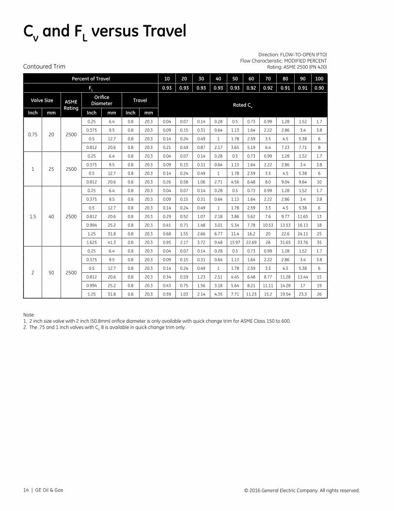
Cv and FL versus Travel
Contoured Trim
Direction: FLOW-TO-OPEN (FTO) Flow Characteristic: MODIFIED PERCENT
Rating: ASME 2500 (PN 420)
Percent of Travel 10 20 30 40 50 60 70 80 90 100
FL 0.93 0.93 0.93 0.93 0.93 0.92 0.92 0.91 0.91 0.90
Valve Size ASME Rating
Orifice Diameter Travel
Rated Cv
Inch mm Inch mm Inch mm
0.75 20 2500
0.25 6.4 0.8 20.3 0.04 0.07 0.14 0.28 0.5 0.73 0.99 1.28 1.52 1.7
0.375 9.5 0.8 20.3 0.09 0.15 0.31 0.64 1.13 1.64 2.22 2.86 3.4 3.8
0.5 12.7 0.8 20.3 0.14 0.24 0.49 1 1.78 2.59 3.5 4.5 5.38 6
0.812 20.6 0.8 20.3 0.21 0.49 0.87 2.17 3.65 5.19 6.4 7.23 7.71 8
1 25 2500
0.25 6.4 0.8 20.3 0.04 0.07 0.14 0.28 0.5 0.73 0.99 1.28 1.52 1.7
0.375 9.5 0.8 20.3 0.09 0.15 0.31 0.64 1.13 1.64 2.22 2.86 3.4 3.8
0.5 12.7 0.8 20.3 0.14 0.24 0.49 1 1.78 2.59 3.5 4.5 5.38 6
0.812 20.6 0.8 20.3 0.26 0.58 1.06 2.71 4.56 6.48 8.0 9.04 9.64 10
1.5 40 2500
0.25 6.4 0.8 20.3 0.04 0.07 0.14 0.28 0.5 0.73 0.99 1.28 1.52 1.7
0.375 9.5 0.8 20.3 0.09 0.15 0.31 0.64 1.13 1.64 2.22 2.86 3.4 3.8
0.5 12.7 0.8 20.3 0.14 0.24 0.49 1 1.78 2.59 3.5 4.5 5.38 6
0.812 20.6 0.8 20.3 0.29 0.52 1.07 2.18 3.86 5.62 7.6 9.77 11.65 13
0.994 25.2 0.8 20.3 0.41 0.71 1.48 3.01 5.34 7.78 10.53 13.53 16.13 18
1.25 31.8 0.8 20.3 0.68 1.55 2.66 6.77 11.4 16.2 20 22.6 24.11 25
1.625 41.3 0.8 20.3 0.95 2.17 3.72 9.48 15.97 22.69 28 31.65 33.76 35
2 50 2500
0.25 6.4 0.8 20.3 0.04 0.07 0.14 0.28 0.5 0.73 0.99 1.28 1.52 1.7
0.375 9.5 0.8 20.3 0.09 0.15 0.31 0.64 1.13 1.64 2.22 2.86 3.4 3.8
0.5 12.7 0.8 20.3 0.14 0.24 0.49 1 1.78 2.59 3.5 4.5 5.38 6
0.812 20.6 0.8 20.3 0.34 0.59 1.23 2.51 4.45 6.48 8.77 11.28 13.44 15
0.994 25.2 0.8 20.3 0.43 0.75 1.56 3.18 5.64 8.21 11.11 14.28 17 19
1.25 31.8 0.8 20.3 0.59 1.03 2.14 4.35 7.71 11.23 15.2 19.54 23.3 26
Note:1. 2 inch size valve with 2 inch (50.8mm) orifice diameter is only available with quick change trim for ASME Class 150 to 600.2. The .75 and 1 inch valves with Cv 8 is available in quick change trim only.
21000 Series Control Valves Technical Specifications | 15© 2016 General Electric Company. All rights reserved.
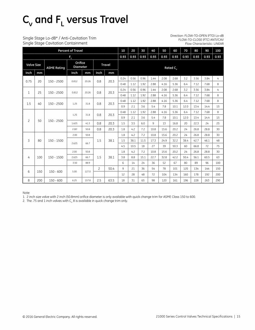
Direction: FLOW-TO-OPEN (FTO) Lo-dBFLOW-TO-CLOSE (FTC) ANTI/CAV
Flow Characteristic: LINEAR
Single Stage Lo-dB* / Anti-Cavitation Trim Single Stage Cavitation Containment
Cv and FL versus Travel
Percent of Travel 10 20 30 40 50 60 70 80 90 100
FL 0.93 0.93 0.93 0.93 0.93 0.93 0.93 0.93 0.93 0.93
Valve SizeASME Rating
Orifice Diameter Travel
Rated Cv
Inch mm Inch mm Inch mm
0.75 20 150 - 2500 0.812 20.26 0.8 20.30.24 0.56 0.96 1.44 2.08 2.68 3.2 3.56 3.84 4
0.48 1.12 1.92 2.88 4.16 5.36 6.4 7.12 7.68 8
1 25 150 - 2500 0.812 20.26 0.8 20.30.24 0.56 0.96 1.44 2.08 2.68 3.2 3.56 3.84 4
0.48 1.12 1.92 2.88 4.16 5.36 6.4 7.12 7.68 8
1.5 40 150 - 2500 1.25 31.8 0.8 20.30.48 1.12 1.92 2.88 4.16 5.36 6.4 7.12 7.68 8
0.9 2.1 3.6 5.4 7.8 10.1 12.0 13.4 14.4 15
2 50 150 - 2500
1.25 31.8 0.8 20.30.48 1.12 1.92 2.88 4.16 5.36 6.4 7.12 7.68 8
0.9 2.1 3.6 5.4 7.8 10.1 12.0 13.4 14.4 15
1.625 41.3 0.8 20.3 1.5 3.5 6.0 9 13 16.8 20 22.3 24 25
2.001 50.8 0.8 20.3 1.8 4.2 7.2 10.8 15.6 20.2 24 26.8 28.8 30
3 80 150 - 1500
2.00 50.8
1.5 38.1
1.8 4.2 7.2 10.8 15.6 20.2 24 26.8 28.8 30
2.625 66.71.5 38.1 11.5 17.3 24.9 32.2 38.4 42.7 46.1 48
4.5 10.5 18 27 39 50.3 60 66.8 72 75
4 100 150 - 1500
2.00 50.8
1.5 38.1
1.8 4.2 7.2 10.8 15.6 20.2 24 26.8 28.8 30
2.625 66.7 3.8 8.8 15.1 22.7 32.8 42.2 50.4 56.1 60.5 63
3.50 88.9 6 14 24 36 52 67 80 89 96 100
6 150 150 - 600 5.00 127.02 50.4 9 21 36 54 78 101 120 134 144 150
12 28 48 72 104 134 160 178 192 200
8 200 150 - 600 6.25 157.8 2.5 63.5 18 31 65 98 120 161 196 228 263 290
Note:1. 2 inch size valve with 2 inch (50.8mm) orifice diameter is only available with quick change trim for ASME Class 150 to 600.2. The .75 and 1 inch valves with Cv 8 is available in quick change trim only.
16 | GE Oil & Gas © 2016 General Electric Company. All rights reserved.
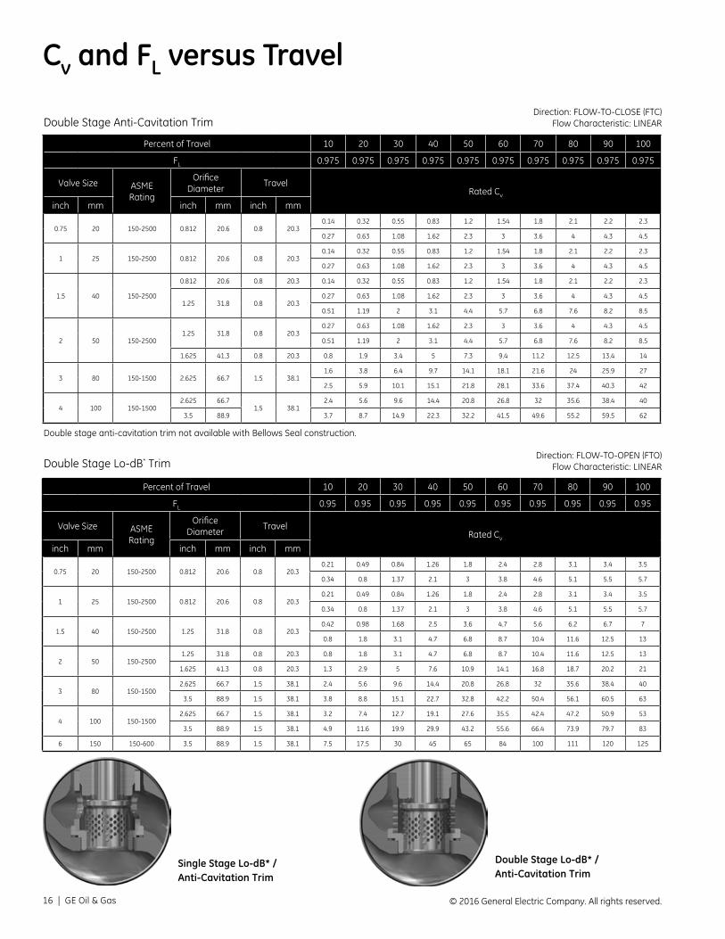
Cv and FL versus Travel
Double Stage Lo-dB* / Anti-Cavitation Trim
Single Stage Lo-dB* / Anti-Cavitation Trim
Double Stage Anti-Cavitation Trim
Double stage anti-cavitation trim not available with Bellows Seal construction.
Double Stage Lo-dB* Trim
Direction: FLOW-TO-CLOSE (FTC) Flow Characteristic: LINEAR
Direction: FLOW-TO-OPEN (FTO) Flow Characteristic: LINEAR
Percent of Travel 10 20 30 40 50 60 70 80 90 100
FL 0.975 0.975 0.975 0.975 0.975 0.975 0.975 0.975 0.975 0.975
Valve Size ASME Rating
Orifice Diameter
TravelRated Cv
inch mm inch mm inch mm
0.75 20 150-2500 0.812 20.6 0.8 20.30.14 0.32 0.55 0.83 1.2 1.54 1.8 2.1 2.2 2.3
0.27 0.63 1.08 1.62 2.3 3 3.6 4 4.3 4.5
1 25 150-2500 0.812 20.6 0.8 20.30.14 0.32 0.55 0.83 1.2 1.54 1.8 2.1 2.2 2.3
0.27 0.63 1.08 1.62 2.3 3 3.6 4 4.3 4.5
1.5 40 150-2500
0.812 20.6 0.8 20.3 0.14 0.32 0.55 0.83 1.2 1.54 1.8 2.1 2.2 2.3
1.25 31.8 0.8 20.30.27 0.63 1.08 1.62 2.3 3 3.6 4 4.3 4.5
0.51 1.19 2 3.1 4.4 5.7 6.8 7.6 8.2 8.5
2 50 150-25001.25 31.8 0.8 20.3
0.27 0.63 1.08 1.62 2.3 3 3.6 4 4.3 4.5
0.51 1.19 2 3.1 4.4 5.7 6.8 7.6 8.2 8.5
1.625 41.3 0.8 20.3 0.8 1.9 3.4 5 7.3 9.4 11.2 12.5 13.4 14
3 80 150-1500 2.625 66.7 1.5 38.11.6 3.8 6.4 9.7 14.1 18.1 21.6 24 25.9 27
2.5 5.9 10.1 15.1 21.8 28.1 33.6 37.4 40.3 42
4 100 150-15002.625 66.7
1.5 38.12.4 5.6 9.6 14.4 20.8 26.8 32 35.6 38.4 40
3.5 88.9 3.7 8.7 14.9 22.3 32.2 41.5 49.6 55.2 59.5 62
Percent of Travel 10 20 30 40 50 60 70 80 90 100
FL 0.95 0.95 0.95 0.95 0.95 0.95 0.95 0.95 0.95 0.95
Valve Size ASME Rating
Orifice Diameter
TravelRated Cv
inch mm inch mm inch mm
0.75 20 150-2500 0.812 20.6 0.8 20.30.21 0.49 0.84 1.26 1.8 2.4 2.8 3.1 3.4 3.5
0.34 0.8 1.37 2.1 3 3.8 4.6 5.1 5.5 5.7
1 25 150-2500 0.812 20.6 0.8 20.30.21 0.49 0.84 1.26 1.8 2.4 2.8 3.1 3.4 3.5
0.34 0.8 1.37 2.1 3 3.8 4.6 5.1 5.5 5.7
1.5 40 150-2500 1.25 31.8 0.8 20.30.42 0.98 1.68 2.5 3.6 4.7 5.6 6.2 6.7 7
0.8 1.8 3.1 4.7 6.8 8.7 10.4 11.6 12.5 13
2 50 150-25001.25 31.8 0.8 20.3 0.8 1.8 3.1 4.7 6.8 8.7 10.4 11.6 12.5 13
1.625 41.3 0.8 20.3 1.3 2.9 5 7.6 10.9 14.1 16.8 18.7 20.2 21
3 80 150-15002.625 66.7 1.5 38.1 2.4 5.6 9.6 14.4 20.8 26.8 32 35.6 38.4 40
3.5 88.9 1.5 38.1 3.8 8.8 15.1 22.7 32.8 42.2 50.4 56.1 60.5 63
4 100 150-15002.625 66.7 1.5 38.1 3.2 7.4 12.7 19.1 27.6 35.5 42.4 47.2 50.9 53
3.5 88.9 1.5 38.1 4.9 11.6 19.9 29.9 43.2 55.6 66.4 73.9 79.7 83
6 150 150-600 3.5 88.9 1.5 38.1 7.5 17.5 30 45 65 84 100 111 120 125
21000 Series Control Valves Technical Specifications | 17© 2016 General Electric Company. All rights reserved.
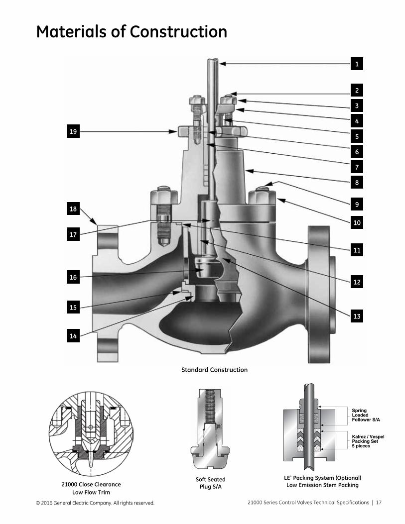
Materials of Construction
LE* Packing System (Optional)Low Emission Stem Packing
Kalrez / VespelPacking Set5 pieces
SpringLoadedFollower S/A
Soft SeatedPlug S/A21000 Close Clearance
Low Flow Trim
Standard Construction
19
18
17
16
15
14
1
2
3
4
5
6
7
8
9
10
11
12
13
18 | GE Oil & Gas © 2016 General Electric Company. All rights reserved.
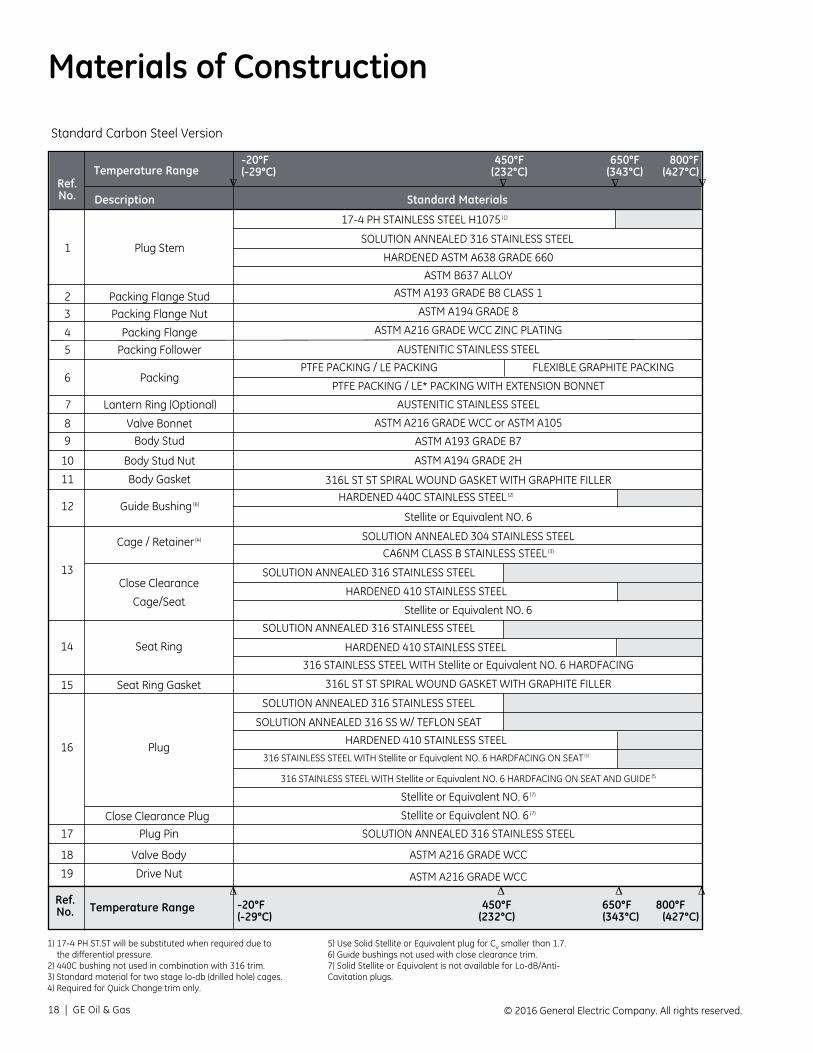
Materials of Construction
Standard Carbon Steel Version
1) 17-4 PH ST.ST will be substituted when required due to the differential pressure.2) 440C bushing not used in combination with 316 trim.3) Standard material for two stage lo-db (drilled hole) cages.4) Required for Quick Change trim only.
5) Use Solid Stellite or Equivalent plug for Cv smaller than 1.7.6) Guide bushings not used with close clearance trim.7) Solid Stellite or Equivalent is not available for Lo-dB/Anti-Cavitation plugs.
Ref.No. Description Standard Materials
1 Plug Stem
2 Packing Flange Stud
3 Packing Flange Nut
4 Packing Flange
5 Packing Follower
6 Packing
7 Lantern Ring (Optional)
8 Valve Bonnet
9 Body Stud
10 Body Stud Nut
11 Body Gasket
12 Guide Bushing (6)
Cage / Retainer (4)
13 Close Clearance
Cage/Seat
14 Seat Ring
15 Seat Ring Gasket
16 Plug
17 Plug Pin
18 Valve Body
19 Drive Nut
Temperature Range -20°F 450°F 650°F 800°F
(-29°C) (232°C) (343°C) (427°C) D DDD
15 Close Clearance Plug
Ref.No. Temperature Range -20°F 450°F 650°F 800°F
(-29°C) (232°C) (343°C) (427°C)
D DD D
17-4 PH STAINLESS STEEL H1075 (1)
SOLUTION ANNEALED 316 STAINLESS STEEL
HARDENED ASTM A638 GRADE 660
ASTM B637 ALLOY
ASTM A193 GRADE B8 CLASS 1
ASTM A194 GRADE 8
ASTM A216 GRADE WCC ZINC PLATING
AUSTENITIC STAINLESS STEEL
PTFE PACKING / LE* PACKING WITH EXTENSION BONNET
AUSTENITIC STAINLESS STEEL
ASTM A216 GRADE WCC or ASTM A105
ASTM A193 GRADE B7
ASTM A194 GRADE 2H
316L ST ST SPIRAL WOUND GASKET WITH GRAPHITE FILLER
Stellite or Equivalent NO. 6
SOLUTION ANNEALED 304 STAINLESS STEEL
Stellite or Equivalent NO. 6
316 STAINLESS STEEL WITH Stellite or Equivalent NO. 6 HARDFACING
316 STAINLESS STEEL WITH Stellite or Equivalent NO. 6 HARDFACING ON SEAT AND GUIDE (5
Stellite or Equivalent NO. 6 (7)
Stellite or Equivalent NO. 6 (7)
SOLUTION ANNEALED 316 STAINLESS STEEL
ASTM A216 GRADE WCC
ASTM A216 GRADE WCC
316L ST ST SPIRAL WOUND GASKET WITH GRAPHITE FILLER
CA6NM CLASS B STAINLESS STEEL (3)
HARDENED 440C STAINLESS STEEL (2)
SOLUTION ANNEALED 316 STAINLESS STEEL
SOLUTION ANNEALED 316 STAINLESS STEEL
HARDENED 410 STAINLESS STEEL
SOLUTION ANNEALED 316 STAINLESS STEEL
SOLUTION ANNEALED 316 SS W/ TEFLON SEAT
HARDENED 410 STAINLESS STEEL
316 STAINLESS STEEL WITH Stellite or Equivalent NO. 6 HARDFACING ON SEAT (5)
HARDENED 410 STAINLESS STEEL
PTFE PACKING / LE PACKING FLEXIBLE GRAPHITE PACKING
21000 Series Control Valves Technical Specifications | 19© 2016 General Electric Company. All rights reserved.
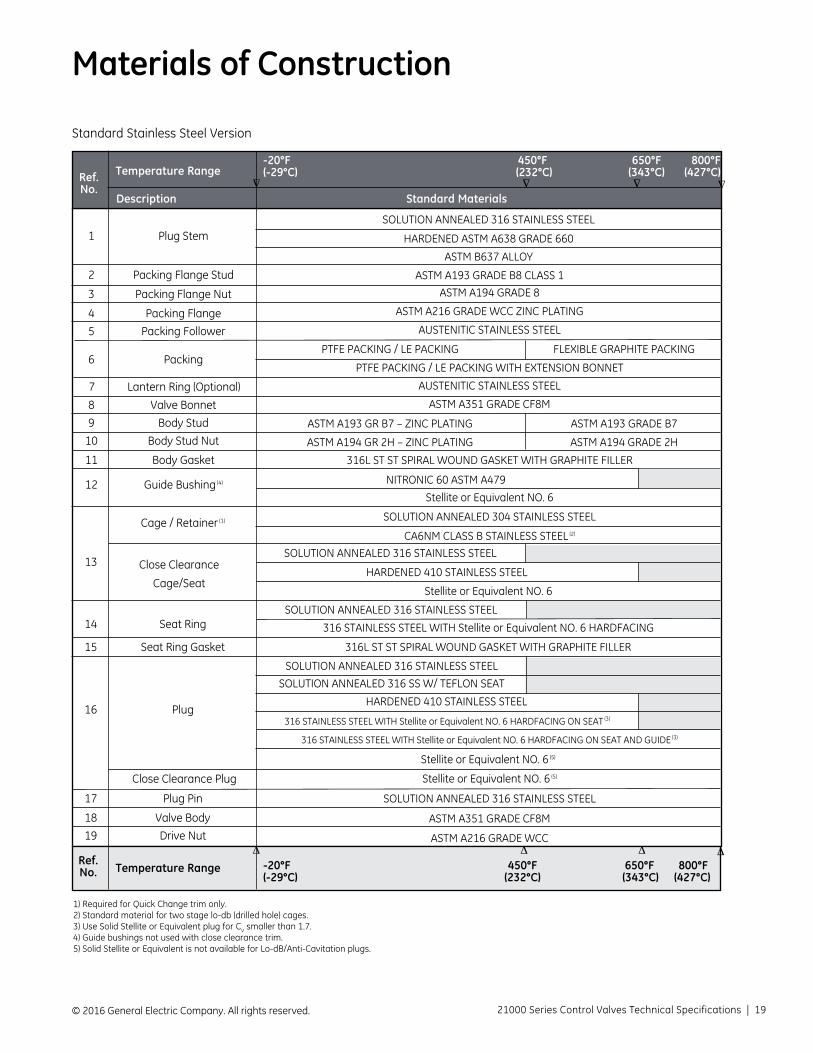
Materials of Construction
SOLUTION ANNEALED 316 SS W/ TEFLON SEAT
Standard Stainless Steel Version
Ref.No.
Description Standard Materials
Temperature Range -20°F 450°F 650°F 800°F
(-29°C) (232°C) (343°C) (427°C) D DD
1) Required for Quick Change trim only.2) Standard material for two stage lo-db (drilled hole) cages.3) Use Solid Stellite or Equivalent plug for Cv smaller than 1.7.4) Guide bushings not used with close clearance trim.5) Solid Stellite or Equivalent is not available for Lo-dB/Anti-Cavitation plugs.
1 Plug Stem
2 Packing Flange Stud
3 Packing Flange Nut
4 Packing Flange
5 Packing Follower
6 Packing
7 Lantern Ring (Optional)
8 Valve Bonnet
9 Body Stud
10 Body Stud Nut
11 Body Gasket
12 Guide Bushing (4)
Cage / Retainer (1)
Close Clearance
Cage/Seat
14 Seat Ring
15 Seat Ring Gasket
16 Plug
17 Plug Pin
18 Valve Body
19 Drive Nut
13
15 Close Clearance Plug
Ref.No. Temperature Range -20°F 450°F 650°F 800°F
(-29°C) (232°C) (343°C) (427°C)
DDD DD
ASTM B637 ALLOY
HARDENED ASTM A638 GRADE 660
SOLUTION ANNEALED 316 STAINLESS STEEL
ASTM A193 GRADE B8 CLASS 1
ASTM A194 GRADE 8
ASTM A216 GRADE WCC ZINC PLATING
AUSTENITIC STAINLESS STEEL
PTFE PACKING / LE PACKING WITH EXTENSION BONNET
PTFE PACKING / LE PACKING
ASTM A193 GR B7 – ZINC PLATING
ASTM A194 GR 2H – ZINC PLATING
FLEXIBLE GRAPHITE PACKING
ASTM A193 GRADE B7
ASTM A194 GRADE 2H
AUSTENITIC STAINLESS STEEL
Stellite or Equivalent NO. 6
ASTM A351 GRADE CF8M
316L ST ST SPIRAL WOUND GASKET WITH GRAPHITE FILLER
NITRONIC 60 ASTM A479
SOLUTION ANNEALED 304 STAINLESS STEEL
CA6NM CLASS B STAINLESS STEEL (2)
SOLUTION ANNEALED 316 STAINLESS STEEL
SOLUTION ANNEALED 316 STAINLESS STEEL
Stellite or Equivalent NO. 6 (5)
SOLUTION ANNEALED 316 STAINLESS STEEL
ASTM A351 GRADE CF8M
ASTM A216 GRADE WCC
HARDENED 410 STAINLESS STEEL
SOLUTION ANNEALED 316 STAINLESS STEEL
HARDENED 410 STAINLESS STEEL
316 STAINLESS STEEL WITH Stellite or Equivalent NO. 6 HARDFACING
316L ST ST SPIRAL WOUND GASKET WITH GRAPHITE FILLER
316 STAINLESS STEEL WITH Stellite or Equivalent NO. 6 HARDFACING ON SEAT AND GUIDE (3)
Stellite or Equivalent NO. 6 (5)
316 STAINLESS STEEL WITH Stellite or Equivalent NO. 6 HARDFACING ON SEAT (3)
Stellite or Equivalent NO. 6
20 | GE Oil & Gas © 2016 General Electric Company. All rights reserved.
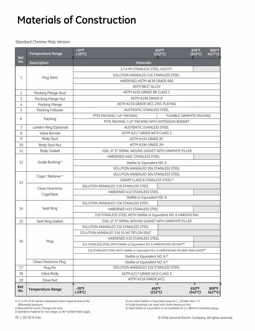
Materials of Construction
SOLUTION ANNEALED 316 STAINLESS STEEL
Standard Chrome Moly Version
Ref.No. Description Materials
1 Plug Stem
2 Packing Flange Stud
3 Packing Flange Nut
4 Packing Flange
5 Packing Follower
6 Packing
7 Lantern Ring (Optional)
8 Valve Bonnet
9 Body Stud
10 Body Stud Nut
11 Body Gasket
12 Guide Bushing (5)
Cage / Retainer (2)
13
Close Clearance
Cage/Seat
14 Seat Ring
15 Seat Ring Gasket
17 Plug Pin
18 Valve Body
19 Drive Nut
Temperature Range -20°F 450°F 650°F 800°F
(-29°C) (232°C) (343°C) (427°C) D DDD
Ref.No. Temperature Range -20°F 450°F 650°F 800°F
(-29°C) (232°C) (343°C) (427°C)
D DDD
15 Close Clearance Plug
17-4 PH STAINLESS STEEL H1075(1)
HARDENED ASTM A638 GRADE 660
ASTM B637 ALLOY
ASTM A193 GRADE B8 CLASS 1
ASTM A194 GRADE 8
ASTM A216 GRADE WCC ZINC PLATING
AUSTENITIC STAINLESS STEEL
PTFE PACKING / LE* PACKING WITH EXTENSION BONNET
PTFE PACKING / LE* PACKING FLEXIBLE GRAPHITE PACKING
ASTM A194 GRADE 2H
SOLUTION ANNEALED 304 STAINLESS STEEL
316 STAINLESS STEEL WITH Stellite or Equivalent NO. 6 HARDFACING
316 STAINLESS STEEL WITH Stellite or Equivalent NO. 6 HARDFACING ON SEAT AND GUIDE(4)
Stellite or Equivalent NO. 6 (6)
ASTM A217 GRADE WC9 CLASS 3
AUSTENITIC STAINLESS STEEL
316L ST ST SPIRAL WOUND GASKET WITH GRAPHITE FILLER
CA6NM CLASS B STAINLESS STEEL(3)
316L ST ST SPIRAL WOUND GASKET WITH GRAPHITE FILLER
Stellite or Equivalent NO. 6 (6)
SOLUTION ANNEALED 316 STAINLESS STEEL
ASTM A216 GRADE WCC
Stellite or Equivalent NO. 6
ASTM A217 GRADE WC9 CLASS 3
HARDENED 440C STAINLESS STEEL
SOLUTION ANNEALED 316 STAINLESS STEEL
SOLUTION ANNEALED 316 STAINLESS STEEL
HARDENED 410 STAINLESS STEEL
SOLUTION ANNEALED 316 STAINLESS STEEL
SOLUTION ANNEALED 316 SS W/ TEFLON SEAT
HARDENED 410 STAINLESS STEEL
316 STAINLESS STEEL WITH Stellite or Equivalent NO. 6 HARDFACING ON SEAT(4)
HARDENED 410 STAINLESS STEEL
ASTM A193 GRADE B7
SOLUTION ANNEALED 304 STAINLESS STEEL
Stellite or Equivalent NO. 6
1) 17-4 PH ST.ST will be substituted when required due to the differential pressure.2) Required for Quick Change trim only.3) Standard material for two stage Lo-db* (drilled hole) cages.
4) Use Solid Stellite or Equivalent plug for Cv smaller than 1.7.5) Guide bushings not used with close clearance trim.6) Solid Stellite or Equivalent is not available for Lo-dB/Anti-Cavitation plugs.
16 Plug
21000 Series Control Valves Technical Specifications | 21© 2016 General Electric Company. All rights reserved.
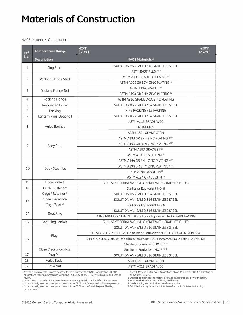
Materials of Construction
SOLUTION ANNEALED 316 STAINLESS STEEL
ASTM B637 ALLOY (2)
ASTM A193 GRADE B8 CLASS 1 (3)
ASTM A193 GR B7M ZINC PLATING (4)
ASTM A194 GRADE 8 (3)
ASTM A194 GR 2HM ZINC PLATING (4)
ASTM A216 GRADE WCC ZINC PLATING
SOLUTION ANNEALED 304 STAINLESS STEEL
PTFE PACKING / LE PACKING
SOLUTION ANNEALED 304 STAINLESS STEEL
ASTM A216 GRADE WCC
ASTM A105
ASTM A351 GRADE CF8M
ASTM A193 GR B7 – ZINC PLATING (3) (7)
ASTM A193 GR B7M ZINC PLATING (4) (7)
ASTM A193 GRADE B7 (3)
ASTM A193 GRADE B7M (4)
ASTM A194 GR 2H – ZINC PLATING (3) (7)
ASTM A194 GR 2HM ZINC PLATING (4) (7)
ASTM A194 GRADE 2H (3)
ASTM A194 GRADE 2HM (4)
316L ST ST SPIRAL WOUND GASKET WITH GRAPHITE FILLER
Stellite or Equivalent NO. 6
SOLUTION ANNEALED 304 STAINLESS STEEL
SOLUTION ANNEALED 316 STAINLESS STEEL
Stellite or Equivalent NO. 6
SOLUTION ANNEALED 316 STAINLESS STEEL
316 STAINLESS STEEL WITH Stellite or Equivalent NO. 6 HARDFACING
316L ST ST SPIRAL WOUND GASKET WITH GRAPHITE FILLER
SOLUTION ANNEALED 316 STAINLESS STEEL
316 STAINLESS STEEL WITH Stellite or Equivalent NO. 6 HARDFACING ON SEAT
316 STAINLESS STEEL WITH Stellite or Equivalent NO. 6 HARDFACING ON SEAT AND GUIDE
Stellite or Equivalent NO. 6 (6) (9)
Stellite or Equivalent NO. 6 (6) (9)
SOLUTION ANNEALED 316 STAINLESS STEEL
ASTM A351 GRADE CF8M
ASTM A216 GRADE WCC
NACE Materials Construction
Ref.No.
Description NACE Materials(1)
Temperature Range -20°F 450°F
(-29°C) (232°C) DD
1) Materials and processes in accordance with the requirements of NACE specification MR0103. Applications requiring compliance to MR0175, 2003 Rev. or ISO 15156 would require engineering review.
2) Inconel 718 will be substituted in applications when required due to the differential pressure.3) Materials designated for these parts conform to NACE Class III (unexposed) bolting requirements. 4) Materials designated for these parts conform to NACE Class I or Class II (exposed) bolting
requirements.
5) Consult Masoneilan for NACE Applications above ANSI Class 600 (PN 100) rating or above 450°F (232°C).
6) Optional component and materials for Close Clearance low flow trim option.7) To be used with stainless steel body and bonnet.8) Guide bushing not used with close clearance trim.9) Solid Stellite or Equivalent is not available for Lo-dB*/Anti-Cavitation plugs.
1 Plug Stem
2 Packing Flange Stud
3 Packing Flange Nut
4 Packing Flange
5 Packing Follower
6 Packing
7 Lantern Ring (Optional)
8 Valve Bonnet
9 Body Stud
10 Body Stud Nut
11 Body Gasket
12 Guide Bushing (8)
Cage / Retainer (4)
Close Clearance
Cage/Seat (6)
14 Seat Ring
15 Seat Ring Gasket
16
Plug
17 Plug Pin
Close Clearance Plug
18 Valve Body
19 Drive Nut
13

22 | GE Oil & Gas © 2016 General Electric Company. All rights reserved.
Materials of Construction
SOLUTION ANNEALED 316 STAINLESS STEEL
HARDENED ASTM A638 GRADE 660
ASTM A193 GRADE B8 CLASS 1
ASTM A194 GRADE 8
ASTM A351 GRADE CF8M
AUSTENITIC STAINLESS STEEL
Teflon™ V-Ring
AUSTENITIC STAINLESS STEEL
ASTM A351 GRADE CF8M [163C](163)
ASTM A312 GRADE TYPE 316
ASTM A479 TYPE 316
ASTM A352 GRADE LCC
ASTM A193 GRADE B8 CLASS 2 (< 3/4" Ø)
< 3/4" Ø OR .75" - 2" Class 150, 300 & 600
3" - 4" Class 150 & 300 ; 3" Class 600
ASTM A453 GRADE 660 CLASS A (3/4"< Ø <1")
3/4" < Ø < 1" OR 1.5"- 2" Class 900 / 1500 ; 1.5" Class 2500
AMS 4676 (> 1" Ø)
> 1" Ø OR .75" - 1" Class 900 / 1500 & 2500
4" - 6" Class 600 ; 2" Class 2500
ASTM A194 GRADE 8
316L ST ST SPIRAL WOUND GASKET WITH GRAPHITE FILLER
Stellite or Equivalent NO. 6 (STANDARD)
NITRONIC 60 ASTM A479 (OPTIONAL)
SOLUTION ANNEALED 304 STAINLESS STEEL (STANDARD)
SOLUTION ANNEALED 316 STAINLESS STEEL (OPTIONAL)
SOLUTION ANNEALED 316 STAINLESS STEEL
316 STAINLESS STEEL WITH Stellite or Equivalent NO. 6 HARDFACING
316L ST ST SPIRAL WOUND GASKET WITH GRAPHITE FILLER
SOLUTION ANNEALED 316 STAINLESS STEEL
316 STAINLESS STEEL WITH Stellite or Equivalent NO. 6 HARDFACING ON SEAT
SOLUTION ANNEALED 316 STAINLESS STEEL
ASTM A351 GRADE CF8M
ASTM A352 GRADE LCC
ASTM A216 GRADE WCC
Cryogenic Construction
1) Materials recommended for Cryogenic Liquid Natural Gas (LNG) applications -320°F (-196°C). Consult factory for suitability in other cryogenic applications.2) Consult factory for NACE applications.3) Trim offerings limited to Quick Change designs only.4) Consult factory for proper actuator sizing to provide correct valve shut-off.5) JIS and EN material equivalents are available.6) Body stud materials also satisfy the requirements of the pressure equipment directive 97/23/EC.
Ref.No. Description (3) (4) Standard Materials (1) (2) (5)
Ref.No.
1 Plug Stem
2 Packing Flange Stud
3 Packing Flange Nut
4 Packing Flange
5 Packing Follower
6 Packing
7 Lantern Ring (Optional)
8 Valve Bonnet
9 Body Stud (6)
10 Body Stud Nut
11 Body Gasket
12 Guide Bushing
Cage 13
14 Seat Ring
15 Seat Ring Gasket
16 Plug
17 Plug Pin
18 Valve Body
19 Drive Nut
Temperature Range -320°F -50°F -20°F
(-196°C) (-46°C) (-29°C) D DTemperature Range -320°F -50°F -20°F (-196°C) (-46°C) (-29°C)
D DD
D
21000 Series Control Valves Technical Specifications | 23© 2016 General Electric Company. All rights reserved.
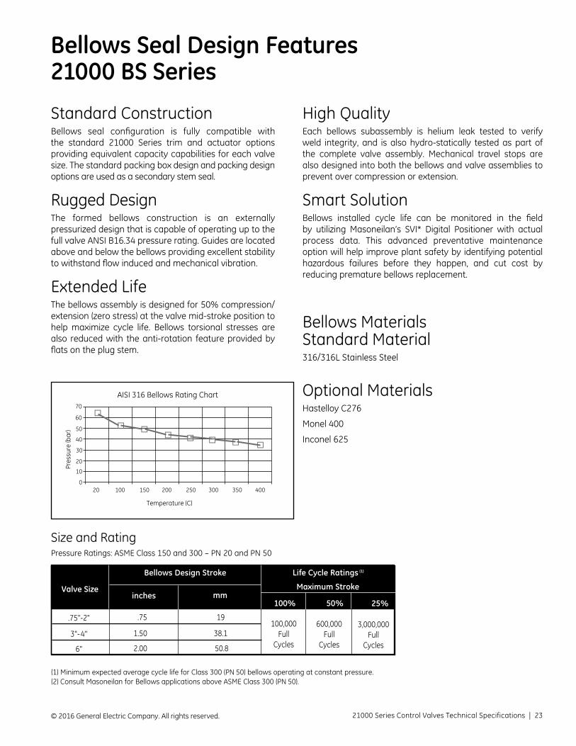
Standard Construction Bellows seal configuration is fully compatible with the standard 21000 Series trim and actuator options providing equivalent capacity capabilities for each valve size. The standard packing box design and packing design options are used as a secondary stem seal.
Rugged Design The formed bellows construction is an externally pressurized design that is capable of operating up to the full valve ANSI B16.34 pressure rating. Guides are located above and below the bellows providing excellent stability to withstand flow induced and mechanical vibration.
Extended LifeThe bellows assembly is designed for 50% compression/extension (zero stress) at the valve mid-stroke position to help maximize cycle life. Bellows torsional stresses are also reduced with the anti-rotation feature provided by flats on the plug stem.
High QualityEach bellows subassembly is helium leak tested to verify weld integrity, and is also hydro-statically tested as part of the complete valve assembly. Mechanical travel stops are also designed into both the bellows and valve assemblies to prevent over compression or extension.
Smart SolutionBellows installed cycle life can be monitored in the field by utilizing Masoneilan’s SVI* Digital Positioner with actual process data. This advanced preventative maintenance option will help improve plant safety by identifying potential hazardous failures before they happen, and cut cost by reducing premature bellows replacement.
Bellows Materials Standard Material316/316L Stainless Steel
Optional MaterialsHastelloy C276
Monel 400
Inconel 625
100% 50%
Valve Size
Bellows Design Stroke
25%
Life Cycle Ratings (1)
Maximum Stroke
.75"-2"
3"-4"
6"
.75 19
1.50 38.1
2.00 50.8
inches
100,000Full
Cycles
600,000Full
Cycles
3,000,000Full
Cycles
Size and RatingsPressure Ratings: ASME Class 150 and 300 – PN 20 and PN 50
(1) Minimum expected average cycle life for Class 300 (PN 50) bellows operating at constant pressure. (2) Consult Masoneilan for Bellows applications above ASME Class 300 (PN 50).
mm
Bellows Seal Design Features 21000 BS Series
Temperature (C)
¨
¨ ¨¨ ¨ ¨ ¨ ¨
AISI 316 Bellows Rating Chart
Pres
sure
(bar
)
20 100 150 200 250 300 350 400
70
60
50
40
30
20
10
0
Size and Rating
24 | GE Oil & Gas © 2016 General Electric Company. All rights reserved.
Materials of Construction
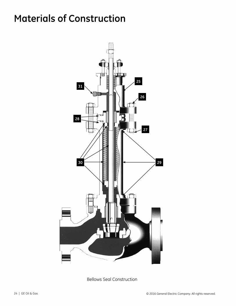
Bellows Seal Construction
25
26
27
2930
28
31
21000 Series Control Valves Technical Specifications | 25© 2016 General Electric Company. All rights reserved.
Materials of Construction
ASTM A216 GRADE WCC or ASTM A105
ASTM A106 GRADE B HRC 22 MAXIMUM
ASTM A216 GRADE WCC
SOLUTION ANNEALED 316 STAINLESS STEEL
ASTM A479
316 ST. ST. ASTM A240/A312
GENERAL SERVICE ANNEALED 316L ST ST
ASTM B574
Stellite or Equivalent NO. 6
Hastelloy C276 ASTM B575/B622
ASTM B574
ASTM B164 CLASS A
Stellite or Equivalent NO. 6
ASTM B164 CLASS A
ASTM B164 CLASS A
INCONEL X-750
Stellite or Equivalent NO. 6
ASTM B446
ASTM B446
ASTM A234 GRADE WPB
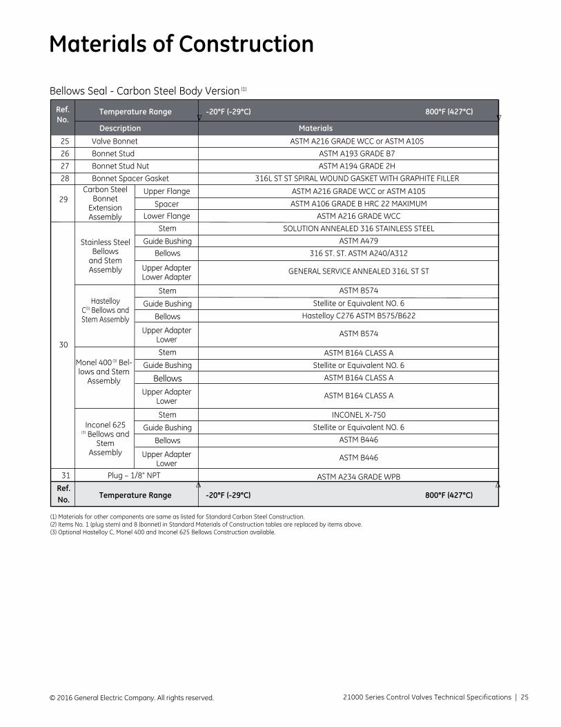
25 Valve Bonnet ASTM A216 GRADE WCC or ASTM A105
26 Bonnet Stud ASTM A193 GRADE B7
27 Bonnet Stud Nut ASTM A194 GRADE 2H
28 Bonnet Spacer Gasket 316L ST ST SPIRAL WOUND GASKET WITH GRAPHITE FILLER
Ref. No.
Bellows Seal - Carbon Steel Body Version (1)
Ref. No.
(1) Materials for other components are same as listed for Standard Carbon Steel Construction.(2) Items No. 1 (plug stem) and 8 (bonnet) in Standard Materials of Construction tables are replaced by items above.(3) Optional Hastelloy C, Monel 400 and Inconel 625 Bellows Construction available.
Carbon Steel Bonnet
Extension Assembly
29Upper Flange
Spacer
Lower Flange
Stainless Steel Bellows
and Stem Assembly
Stem
Guide Bushing
Bellows
Upper AdapterLower Adapter
Hastelloy C(3) Bellows and Stem Assembly
Stem
Guide Bushing
Bellows
Upper AdapterLower
Monel 400 (3) Bel-lows and Stem
Assembly
Stem
Guide Bushing
BellowsUpper Adapter
Lower
Inconel 625
(3) Bellows and Stem
Assembly
Stem
Guide Bushing
Bellows
Upper AdapterLower
30
31 Plug – 1/8" NPT
Temperature Range -20°F (-29°C) 800°F (427°C) Description Materials
D D
Temperature Range -20°F (-29°C) 800°F (427°C)
D D
26 | GE Oil & Gas © 2016 General Electric Company. All rights reserved.
Materials of Construction
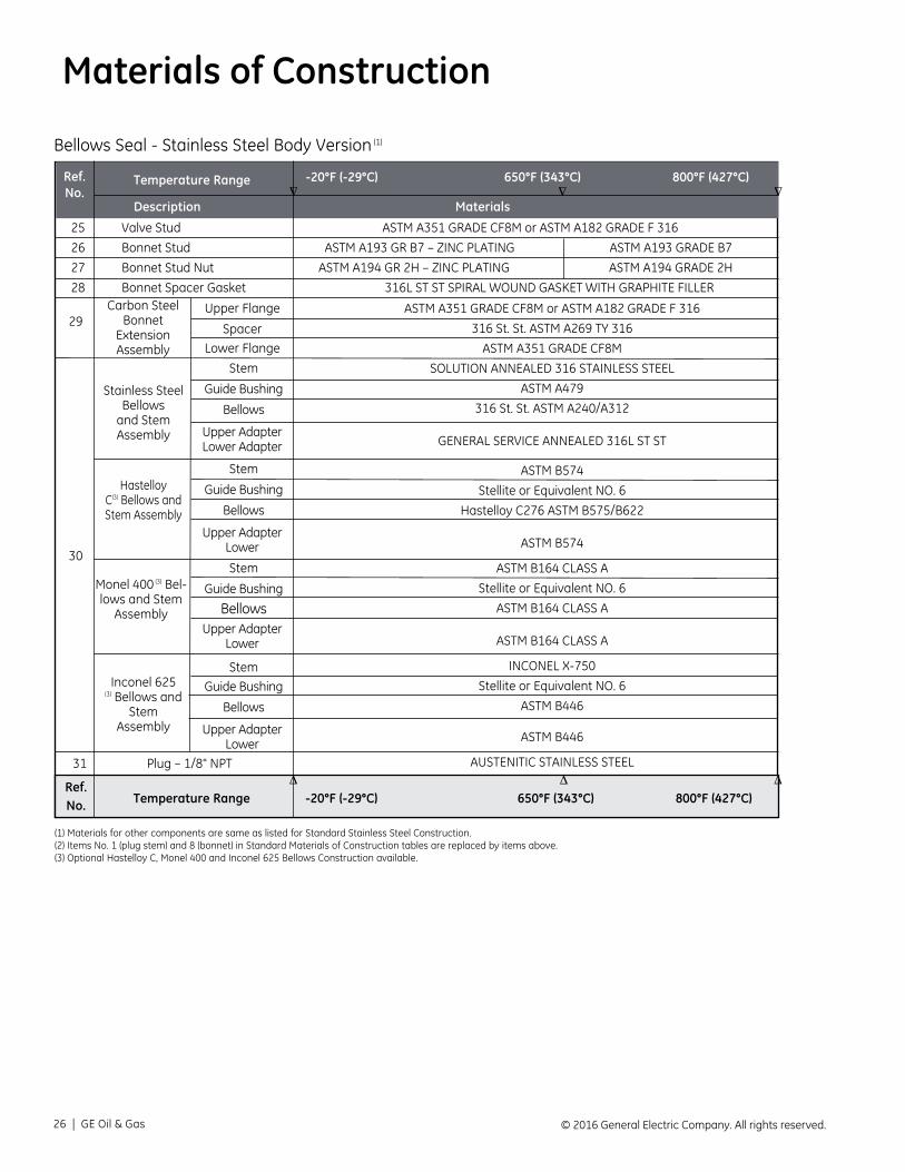
ASTM A351 GRADE CF8M or ASTM A182 GRADE F 316
316 St. St. ASTM A269 TY 316
ASTM A351 GRADE CF8M
SOLUTION ANNEALED 316 STAINLESS STEEL
ASTM A479
316 St. St. ASTM A240/A312
GENERAL SERVICE ANNEALED 316L ST ST
ASTM B574
Stellite or Equivalent NO. 6
Hastelloy C276 ASTM B575/B622
ASTM B574
ASTM B164 CLASS A
Stellite or Equivalent NO. 6
ASTM B164 CLASS A
ASTM B164 CLASS A
INCONEL X-750
Stellite or Equivalent NO. 6
ASTM B446
ASTM B446
AUSTENITIC STAINLESS STEEL
25 Valve Stud ASTM A351 GRADE CF8M or ASTM A182 GRADE F 316
26 Bonnet Stud ASTM A193 GR B7 – ZINC PLATING ASTM A193 GRADE B7
27 Bonnet Stud Nut ASTM A194 GR 2H – ZINC PLATING ASTM A194 GRADE 2H
28 Bonnet Spacer Gasket 316L ST ST SPIRAL WOUND GASKET WITH GRAPHITE FILLER
Ref. No.
Bellows Seal - Stainless Steel Body Version (1)
Ref. No.
(1) Materials for other components are same as listed for Standard Stainless Steel Construction.(2) Items No. 1 (plug stem) and 8 (bonnet) in Standard Materials of Construction tables are replaced by items above.(3) Optional Hastelloy C, Monel 400 and Inconel 625 Bellows Construction available.
Carbon Steel Bonnet
Extension Assembly
29Upper Flange
Spacer
Lower Flange
Stainless Steel Bellows
and Stem Assembly
Stem
Guide Bushing
Bellows
Upper AdapterLower Adapter
Hastelloy C(3) Bellows and Stem Assembly
Stem
Guide Bushing
Bellows
Upper AdapterLower
Monel 400 (3) Bel-lows and Stem
Assembly
Stem
Guide Bushing
BellowsUpper Adapter
Lower
Inconel 625
(3) Bellows and Stem
Assembly
Stem
Guide Bushing
Bellows
Upper AdapterLower
30
31 Plug – 1/8" NPT
Temperature Range -20°F (-29°C) 650°F (343°C) 800°F (427°C) Description Materials
D D
Temperature Range -20°F (-29°C) 650°F (343°C) 800°F (427°C) D D
D
D
21000 Series Control Valves Technical Specifications | 27© 2016 General Electric Company. All rights reserved.
B
A
B
A
C
C
D
D
C
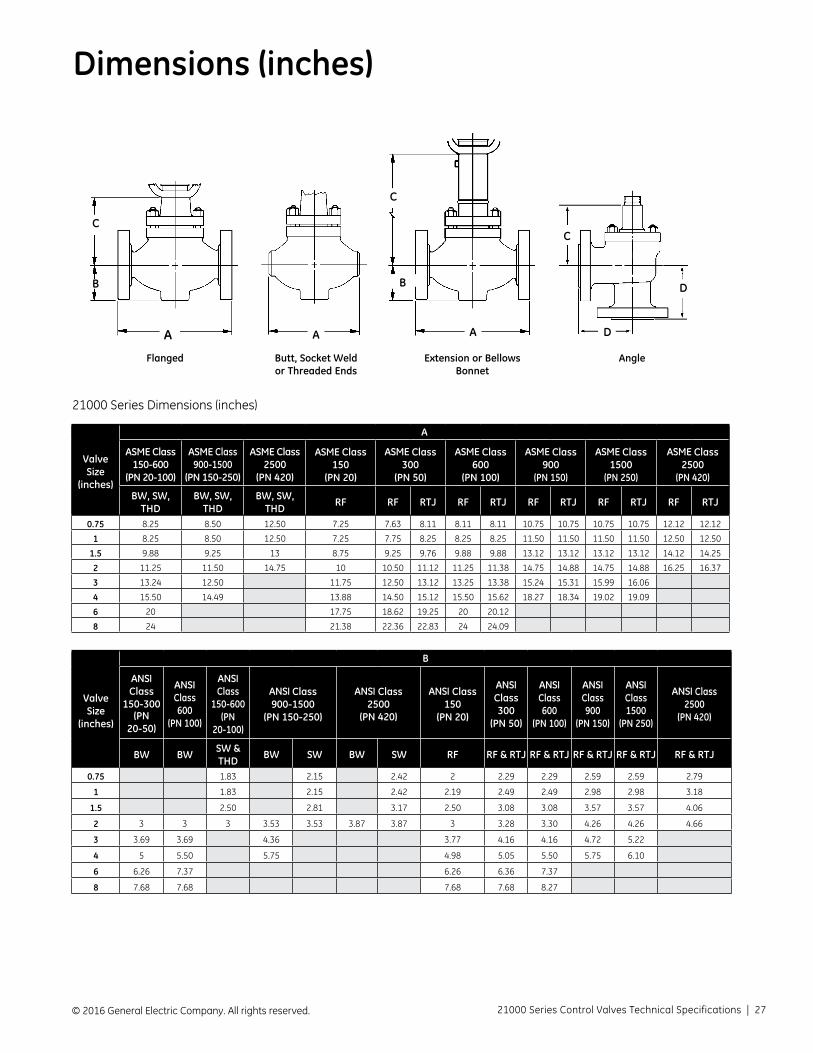
Flanged Butt, Socket Weldor Threaded Ends
Extension or Bellows Bonnet
Angle
21000 Series Dimensions (inches)
Valve Size
(inches)
A
ASME Class150-600
(PN 20-100)
ASME Class900-1500
(PN 150-250)
ASME Class2500
(PN 420)
ASME Class 150
(PN 20)
ASME Class300
(PN 50)
ASME Class600
(PN 100)
ASME Class900
(PN 150)
ASME Class1500
(PN 250)
ASME Class2500
(PN 420)
BW, SW, THD
BW, SW, THD
BW, SW, THD RF RF RTJ RF RTJ RF RTJ RF RTJ RF RTJ
0.75 8.25 8.50 12.50 7.25 7.63 8.11 8.11 8.11 10.75 10.75 10.75 10.75 12.12 12.12
1 8.25 8.50 12.50 7.25 7.75 8.25 8.25 8.25 11.50 11.50 11.50 11.50 12.50 12.50
1.5 9.88 9.25 13 8.75 9.25 9.76 9.88 9.88 13.12 13.12 13.12 13.12 14.12 14.25
2 11.25 11.50 14.75 10 10.50 11.12 11.25 11.38 14.75 14.88 14.75 14.88 16.25 16.37
3 13.24 12.50 11.75 12.50 13.12 13.25 13.38 15.24 15.31 15.99 16.06
4 15.50 14.49 13.88 14.50 15.12 15.50 15.62 18.27 18.34 19.02 19.09
6 20 17.75 18.62 19.25 20 20.12
8 24 21.38 22.36 22.83 24 24.09
Valve Size
(inches)
B
ANSI Class
150-300(PN
20-50)
ANSI Class600
(PN 100)
ANSI Class
150-600(PN
20-100)
ANSI Class900-1500
(PN 150-250)
ANSI Class2500
(PN 420)
ANSI Class150
(PN 20)
ANSI Class 300
(PN 50)
ANSI Class 600
(PN 100)
ANSI Class900
(PN 150)
ANSI Class 1500
(PN 250)
ANSI Class 2500
(PN 420)
BW BW SW & THD BW SW BW SW RF RF & RTJ RF & RTJ RF & RTJ RF & RTJ RF & RTJ
0.75 1.83 2.15 2.42 2 2.29 2.29 2.59 2.59 2.79
1 1.83 2.15 2.42 2.19 2.49 2.49 2.98 2.98 3.18
1.5 2.50 2.81 3.17 2.50 3.08 3.08 3.57 3.57 4.06
2 3 3 3 3.53 3.53 3.87 3.87 3 3.28 3.30 4.26 4.26 4.66
3 3.69 3.69 4.36 3.77 4.16 4.16 4.72 5.22
4 5 5.50 5.75 4.98 5.05 5.50 5.75 6.10
6 6.26 7.37 6.26 6.36 7.37
8 7.68 7.68 7.68 7.68 8.27
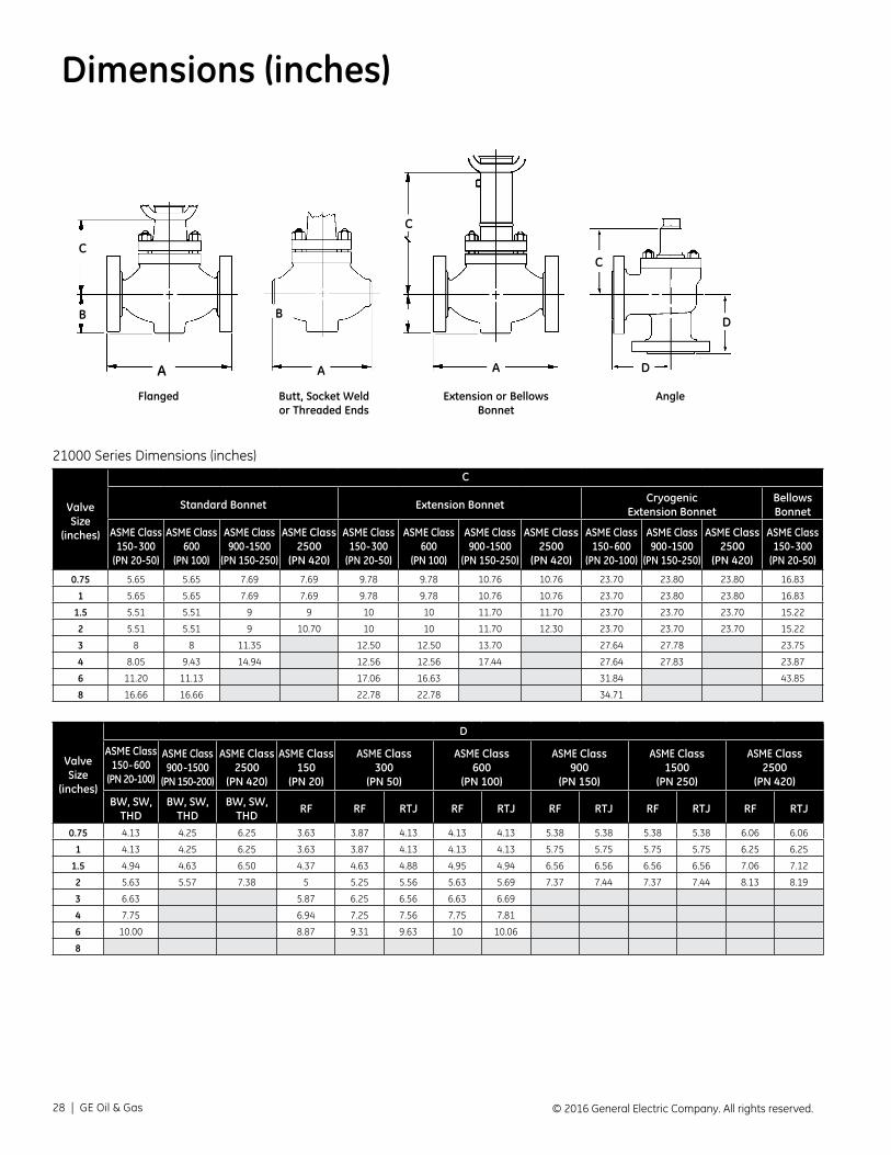
Dimensions (inches)
A
28 | GE Oil & Gas © 2016 General Electric Company. All rights reserved.
Valve Size
(inches)
D
ASME Class150-600
(PN 20-100)
ASME Class900-1500
(PN 150-200)
ASME Class2500
(PN 420)
ASME Class150
(PN 20)
ASME Class300
(PN 50)
ASME Class600
(PN 100)
ASME Class900
(PN 150)
ASME Class1500
(PN 250)
ASME Class2500
(PN 420)
BW, SW, THD
BW, SW, THD
BW, SW, THD RF RF RTJ RF RTJ RF RTJ RF RTJ RF RTJ
0.75 4.13 4.25 6.25 3.63 3.87 4.13 4.13 4.13 5.38 5.38 5.38 5.38 6.06 6.06
1 4.13 4.25 6.25 3.63 3.87 4.13 4.13 4.13 5.75 5.75 5.75 5.75 6.25 6.25
1.5 4.94 4.63 6.50 4.37 4.63 4.88 4.95 4.94 6.56 6.56 6.56 6.56 7.06 7.12
2 5.63 5.57 7.38 5 5.25 5.56 5.63 5.69 7.37 7.44 7.37 7.44 8.13 8.19
3 6.63 5.87 6.25 6.56 6.63 6.69
4 7.75 6.94 7.25 7.56 7.75 7.81
6 10.00 8.87 9.31 9.63 10 10.06
8
Valve Size
(inches)
C
Standard Bonnet Extension Bonnet Cryogenic Extension Bonnet
Bellows Bonnet
ASME Class150-300
(PN 20-50)
ASME Class600
(PN 100)
ASME Class900-1500
(PN 150-250)
ASME Class2500
(PN 420)
ASME Class150-300
(PN 20-50)
ASME Class600
(PN 100)
ASME Class900-1500
(PN 150-250)
ASME Class2500
(PN 420)
ASME Class150-600
(PN 20-100)
ASME Class900-1500
(PN 150-250)
ASME Class2500
(PN 420)
ASME Class150-300
(PN 20-50)
0.75 5.65 5.65 7.69 7.69 9.78 9.78 10.76 10.76 23.70 23.80 23.80 16.83
1 5.65 5.65 7.69 7.69 9.78 9.78 10.76 10.76 23.70 23.80 23.80 16.83
1.5 5.51 5.51 9 9 10 10 11.70 11.70 23.70 23.70 23.70 15.22
2 5.51 5.51 9 10.70 10 10 11.70 12.30 23.70 23.70 23.70 15.22
3 8 8 11.35 12.50 12.50 13.70 27.64 27.78 23.75
4 8.05 9.43 14.94 12.56 12.56 17.44 27.64 27.83 23.87
6 11.20 11.13 17.06 16.63 31.84 43.85
8 16.66 16.66 22.78 22.78 34.71
21000 Series Dimensions (inches)
Dimensions (inches)
B
A
B
A
C
C
D
D
C
Flanged Butt, Socket Weldor Threaded Ends
Extension or Bellows Bonnet
Angle
A
21000 Series Control Valves Technical Specifications | 29© 2016 General Electric Company. All rights reserved.
B
A
B
A
C
C
D
D
C
Flanged Butt, Socket Weldor Threaded Ends
Extension or Bellows Bonnet
Angle
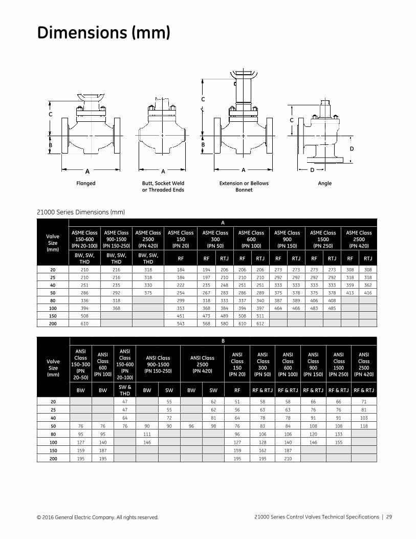
Dimensions (mm)
A
Valve Size
(mm)
A
ASME Class150-600
(PN 20-100)
ASME Class900-1500
(PN 150-250)
ASME Class2500
(PN 420)
ASME Class150
(PN 20)
ASME Class300
(PN 50)
ASME Class600
(PN 100)
ASME Class900
(PN 150)
ASME Class1500
(PN 250)
ASME Class2500
(PN 420)
BW, SW, THD
BW, SW, THD
BW, SW, THD RF RF RTJ RF RTJ RF RTJ RF RTJ RF RTJ
20 210 216 318 184 194 206 206 206 273 273 273 273 308 308
25 210 216 318 184 197 210 210 210 292 292 292 292 318 318
40 251 235 330 222 235 248 251 251 333 333 333 333 359 362
50 286 292 375 254 267 283 286 289 375 378 375 378 413 416
80 336 318 299 318 333 337 340 387 389 406 408
100 394 368 353 368 384 394 397 464 466 483 485
150 508 451 473 489 508 511
200 610 543 568 580 610 612
21000 Series Dimensions (mm)
Valve Size
(mm)
B
ANSI Class
150-300(PN
20-50)
ANSI Class600
(PN 100)
ANSI Class
150-600(PN
20-100)
ANSI Class900-1500
(PN 150-250)
ANSI Class2500
(PN 420)
ANSI Class150
(PN 20)
ANSI Class
300(PN 50)
ANSIClass 600
(PN 100)
ANSI Class900
(PN 150)
ANSI Class 1500
(PN 250)
ANSIClass 2500
(PN 420)
BW BW SW & THD BW SW BW SW RF RF & RTJ RF & RTJ RF & RTJ RF & RTJ RF & RTJ
20 47 55 62 51 58 58 66 66 71
25 47 55 62 56 63 63 76 76 81
40 64 72 81 64 78 78 91 91 103
50 76 76 76 90 90 96 98 76 83 84 108 108 118
80 95 95 111 96 106 106 120 133
100 127 140 146 127 128 140 146 155
150 159 187 159 162 187
200 195 195 195 195 210
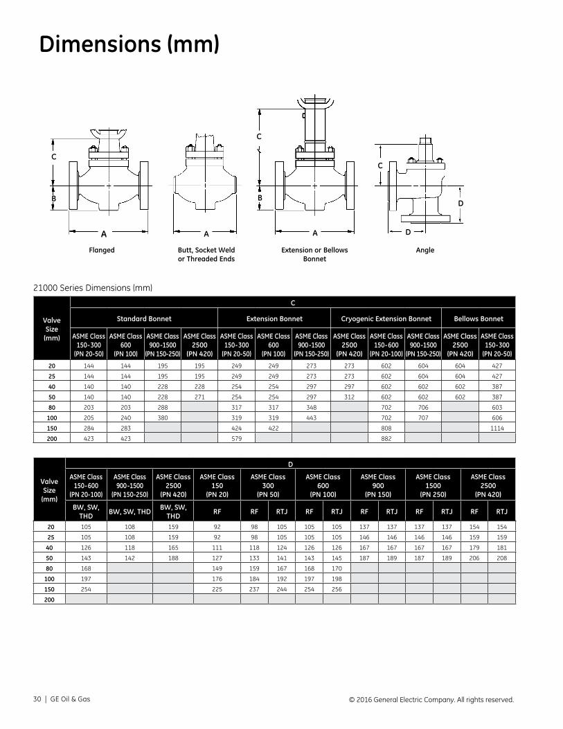
30 | GE Oil & Gas © 2016 General Electric Company. All rights reserved.
Valve Size
(mm)
C
Standard Bonnet Extension Bonnet Cryogenic Extension Bonnet Bellows Bonnet
ASME Class150-300
(PN 20-50)
ASME Class600
(PN 100)
ASME Class900-1500
(PN 150-250)
ASME Class2500
(PN 420)
ASME Class150-300
(PN 20-50)
ASME Class600
(PN 100)
ASME Class900-1500
(PN 150-250)
ASME Class2500
(PN 420)
ASME Class150-600
(PN 20-100)
ASME Class900-1500
(PN 150-250)
ASME Class2500
(PN 420)
ASME Class150-300
(PN 20-50)
20 144 144 195 195 249 249 273 273 602 604 604 427
25 144 144 195 195 249 249 273 273 602 604 604 427
40 140 140 228 228 254 254 297 297 602 602 602 387
50 140 140 228 271 254 254 297 312 602 602 602 387
80 203 203 288 317 317 348 702 706 603
100 205 240 380 319 319 443 702 707 606
150 284 283 424 422 808 1114
200 423 423 579 882
21000 Series Dimensions (mm)
Valve Size
(mm)
D
ASME Class150-600
(PN 20-100)
ASME Class900-1500
(PN 150-250)
ASME Class2500
(PN 420)
ASME Class150
(PN 20)
ASME Class300
(PN 50)
ASME Class600
(PN 100)
ASME Class900
(PN 150)
ASME Class1500
(PN 250)
ASME Class2500
(PN 420)
BW, SW, THD BW, SW, THD BW, SW,
THD RF RF RTJ RF RTJ RF RTJ RF RTJ RF RTJ
20 105 108 159 92 98 105 105 105 137 137 137 137 154 154
25 105 108 159 92 98 105 105 105 146 146 146 146 159 159
40 126 118 165 111 118 124 126 126 167 167 167 167 179 181
50 143 142 188 127 133 141 143 145 187 189 187 189 206 208
80 168 149 159 167 168 170
100 197 176 184 192 197 198
150 254 225 237 244 254 256
200
Dimensions (mm)
B
A
B
A
C
C
D
D
C
Flanged Butt, Socket Weldor Threaded Ends
Extension or Bellows Bonnet
Angle
A
Valve Size (inches)
ASME Class 150 – 300 (PN 20 – 50)
ASME Class600 (PN 100)
ASME Class900 – 1500 (PN 150 – 250)
ASME Class2500 (PN 420)
FLG BW, SW & THD FLG BW, SW & THD FLG BW, SW & THD FLG BW, SW & THD
0.75 36 27 38 27 57 44 70 44
1 36 27 38 27 75 44 90 44
1.5 49 36 53 36 100 57 118 57
2 57 44 64 44 144 82 255 154
3 127 73 128 99 199 146
4 196 121 216 135 409 318
6 355 238 450 272
8 682 610 771 610
Valve Size (mm)
ASME Class 150 – 300 (PN 20 – 50)
ASME Class600 (PN 100)
ASME Class900 – 1500 (PN 150 – 250)
ASME Class2500 (PN 420)
FLG BW, SW & THD FLG BW, SW & THD FLG BW, SW & THD FLG BW, SW & THD
20 16 12 17 12 26 20 32 20
25 16 12 17 12 34 20 41 20
40 22 16 24 16 45 26 53 26
50 26 20 29 20 65 37 116 70
80 58 33 58 45 90 66
100 89 55 98 61 186 144
150 161 108 204 123
200 309 277 350 277
21000 Series Control Valves Technical Specifications | 31© 2016 General Electric Company. All rights reserved.
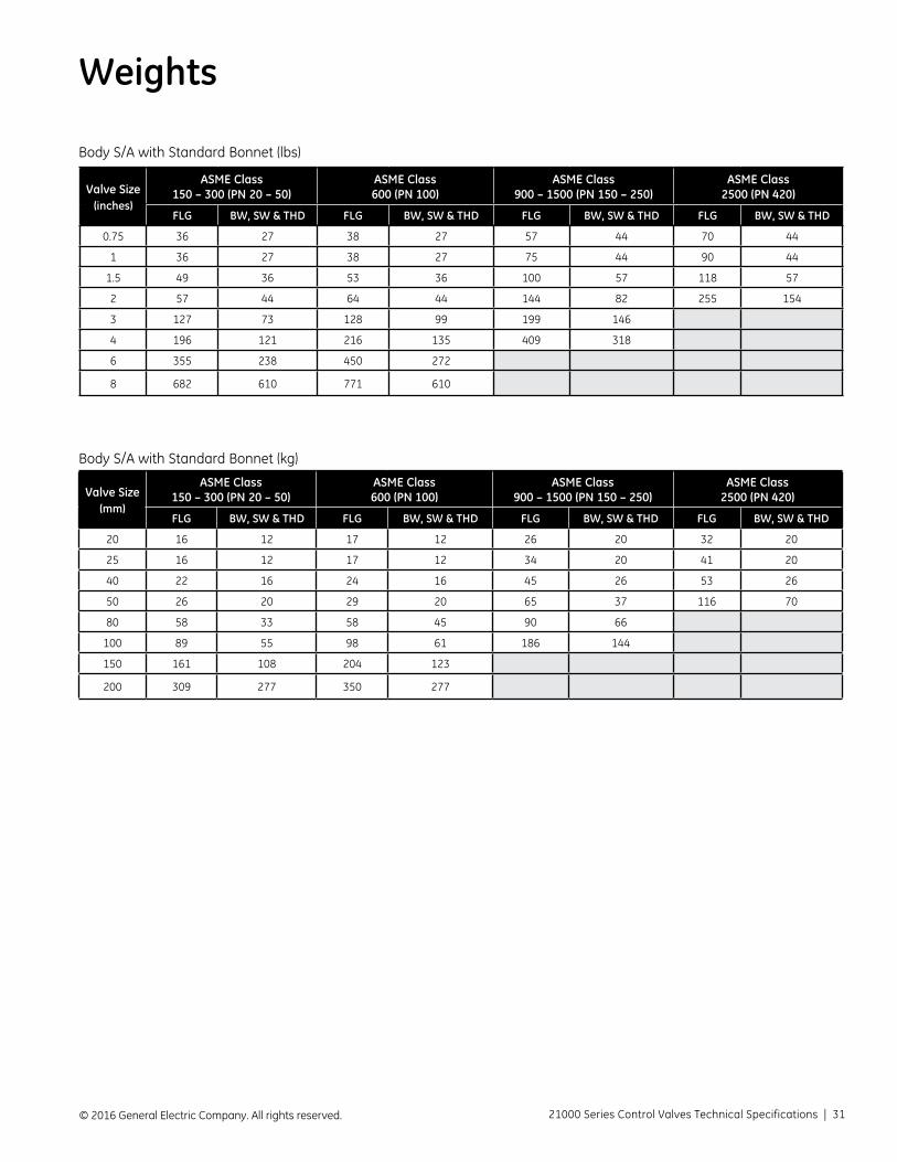
Weights
Body S/A with Standard Bonnet (lbs)
Body S/A with Standard Bonnet (kg)
Valve Size (inches)
ASME Class 150 – 300 (PN 20 – 50)
ASME Class600 (PN 100)
ASME Class900 – 1500 (PN 150 – 250)
ASME Class2500 (PN 420)
FLG BW, SW & THD FLG BW, SW & THD FLG BW, SW & THD FLG BW, SW & THD
0.75 36 27 38 27 57 44 70 44
1 36 27 38 27 75 44 90 44
1.5 49 36 53 36 100 57 118 57
2 57 44 64 44 144 82 255 154
3 127 73 128 99 199 146
4 196 121 216 135 409 318
6 355 238 450 272
8 682 610 771 610
Valve Size (mm)
ASME Class 150 – 300 (PN 20 – 50)
ASME Class600 (PN 100)
ASME Class900 – 1500 (PN 150 – 250)
ASME Class2500 (PN 420)
FLG BW, SW & THD FLG BW, SW & THD FLG BW, SW & THD FLG BW, SW & THD
20 16 12 17 12 26 20 32 20
25 16 12 17 12 34 20 41 20
40 22 16 24 16 45 26 53 26
50 26 20 29 20 65 37 116 70
80 58 33 58 45 90 66
100 89 55 98 61 186 144
150 161 108 204 123
200 309 277 350 277
32 | GE Oil & Gas © 2016 General Electric Company. All rights reserved.
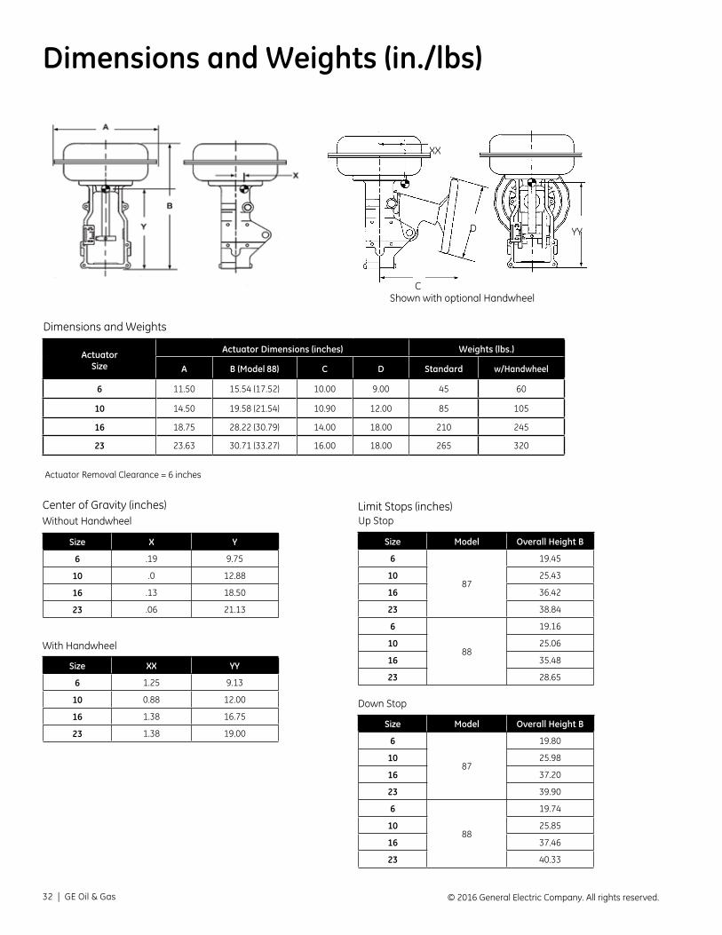
Dimensions and Weights (in./lbs)
Center of Gravity (inches) Limit Stops (inches)
YYD
C
XX
Actuator Removal Clearance = 6 inches
Up StopWithout Handwheel
With Handwheel
Down Stop
Dimensions and Weights
Shown with optional Handwheel
ActuatorSize
Actuator Dimensions (inches) Weights (lbs.)
A B (Model 88) C D Standard w/Handwheel
6 11.50 15.54 (17.52) 10.00 9.00 45 60
10 14.50 19.58 (21.54) 10.90 12.00 85 105
16 18.75 28.22 (30.79) 14.00 18.00 210 245
23 23.63 30.71 (33.27) 16.00 18.00 265 320
Size X Y
6 .19 9.75
10 .0 12.88
16 .13 18.50
23 .06 21.13
Size Model Overall Height B
6
87
19.45
10 25.43
16 36.42
23 38.84
6
88
19.16
10 25.06
16 35.48
23 28.65
Size Model Overall Height B
6
87
19.80
10 25.98
16 37.20
23 39.90
6
88
19.74
10 25.85
16 37.46
23 40.33
Size XX YY
6 1.25 9.13
10 0.88 12.00
16 1.38 16.75
23 1.38 19.00
21000 Series Control Valves Technical Specifications | 33© 2016 General Electric Company. All rights reserved.
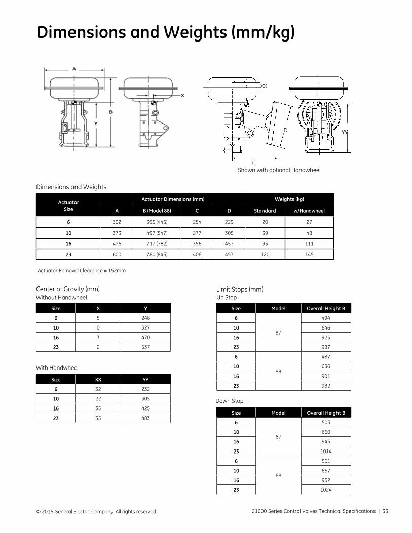
Dimensions and Weights (mm/kg)
Center of Gravity (mm) Limit Stops (mm)
YYD
C
XX
Actuator Removal Clearance = 152mm
Up StopWithout Handwheel
With Handwheel
Down Stop
Dimensions and Weights
Shown with optional Handwheel
ActuatorSize
Actuator Dimensions (mm) Weights (kg)
A B (Model 88) C D Standard w/Handwheel
6 302 395 (445) 254 229 20 27
10 373 497 (547) 277 305 39 48
16 476 717 (782) 356 457 95 111
23 600 780 (845) 406 457 120 145
Size X Y
6 5 248
10 0 327
16 3 470
23 2 537
Size XX YY
6 32 232
10 22 305
16 35 425
23 35 483
Size Model Overall Height B
6
87
494
10 646
16 925
23 987
6
88
487
10 636
16 901
23 982
Size Model Overall Height B
6
87
503
10 660
16 945
23 1014
6
88
501
10 657
16 952
23 1024
DISTRIBUTOR
* Trademark of the General Electric Company.Other company names and product names used in this document arethe registered trademarks or trademarks of their respective owners.
© 2014 General Electric Company. All rights reserved.
Visit your web-site:www.fr-eps.com
E.P. & S. - FRANCE24 bis rue de Picpus75012 PARISTel: +33 (0) 762 682 291Tel: +33 (0) 650 590 [email protected]
E.P. & S. - CAMEROONImmeuble Carré d’OrRue Soppo Priso Côté Chococho, BonaprisoDOUALATel: +237 6 52 12 70 95Tel: +33 (0) 782 006 [email protected]