Maschinenbau Lohse GmbH · Subject to change. 1 Ver. 1529 Maschinenbau Lohse GmbH Waste Technology...
82
Mechanical Engineering Maschinenbau Lohse GmbH ®
Transcript of Maschinenbau Lohse GmbH · Subject to change. 1 Ver. 1529 Maschinenbau Lohse GmbH Waste Technology...
Mechanical Engineering
Maschinenbau Lohse GmbH
®

Subject to change. 1
®
Ver. 1529
Maschinenbau Lohse GmbH
Waste Technology • Bio-mechanical Wet Treatment Plant 5 • Waste pulper 9 • Multisorter 13 • Rejectors 17 • Spiral Conveyors 21 • Sand Separators 23 • Dirt Traps 27 • Vortex Breakers 33 • Dewatering Presses 39 • Mounting and Service 41
Paper Technology • Raking Systems for Waste Paper Pulpers 43 • Rope Cutters 47 • Reject Drums 51 • Vibration Screens 53 • Safety Access Doors 59 • Roller Boards 63 • Construction and production to customer‘s drawings 65 • Repairs 67
Tanks • Pressure Tanks 69
Fans • Axial Fans 73
Manufacturing systems for subcontract work • Cutting 78 • Surface processing methode 78 • Mechanical processing
...and much more! 79

2
®

Subject to change.Ver. 1036 3
®
• QM-Managementsystem to DIN EN ISO 9001 • manufacturer to AD 2000 • certifi ed to DIN EN ISO 3834-2 (quality requirements for welding methods) • manufacturer qualifi cation to DIN 18800 T7 for welding of steel constructions
Class E • qualifi ed welder to EN 287 material groups W01;W03, W11 • qualifi ed welder to DIN EN ISO 15614 material group W01 • approved specialist factory to § 19 I WHG • X-ray test (RT) to EN 473 • Mobile spectral analysis with accuracy to laboratory standard (including C, P
and S) • noise level measurement • authorisation to transfer stamp for certifi cates • surface crack inspection (PT) to EN 473 • sealing test (Nekal) • sealing test to DIN 25412 Part 2 • testing and acceptance acc. pressure vessel directive 97/23 EG • layer thickness measurement • wall thickness measurement • temperature measurement (-50° C to +1150° C)
General approvals / Certifi cates
Maschinenbau Lohse GmbH

M
M
4
®

Siebgutsieving material
SuspensionM
M
M
SiSiSi bSi bbbbSSSiSSiSSSSiSiebbbSSSSSSSieSSSiebSiebbSiebbebSSSSiSiebbSiebSiebebSSSSiSiieSieeeeeSiebebeeeebbebbebieeieebSSieebbbSSSSiSieeeebbebbSS eebbbbbbSSSi bbbSSSSSSSSSSiiiebSSSSSSSS ebbSSSiebSiebSSSSSSiieebbbSSSSSiSSiSSiiieeeeeeeeebbbbbSSSSSSSSiieeeeebeeebbbbb tttttggutttgutgutgguguttgguuguutttttutgggguuugutttgutggugugugutgggugugutgututtggugugg tttgguttttgguutgututtgggutttgggggguuuutttgggggguuuuuututgutgutgggggugugugggsisiesieiiiisiesiesieiisisssieesssieeevvvvvvvvss eeevvvvvvssssieeievvvvsievsiievevsssievsievvvs iiinginnggggggggiiinnnngggggginnngngggggginngnnggingggngiingggngnngginnggg ttttttttmamatmattatematemamattmatematematemmmaatmattmatematemmmmatmamaatemma ii lirialrialrrialr lrrialri lialalria
MMMMMMMMMMMMMMMMMMMMMMMMMMMMMMMMMMMMMMMMMMMMMMMMMMMMMMMMMMM
®
Mechanical Engineering
Maschinenbau Lohse GmbHUnteres Paradies 63 · 89522 HeidenheimPostfach 1565 · 89505 Heidenheimphone +49(0)7321 / 755-79 · fax +49(0)7321 / [email protected] ·www.lohse-gmbh.de
Bio-mechanical Wet Treatment Plant
for biowaste, food-waste and household waste
Subject to change.6
®
Ver. 1508
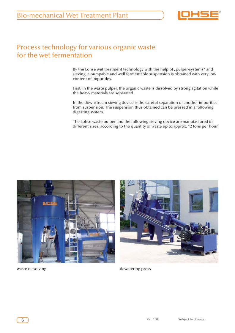
By the Lohse wet treatment technology with the help of „pulper-systems“ and sieving, a pumpable and well fermentable suspension is obtained with very low content of impurities.
First, in the waste pulper, the organic waste is dissolved by strong agitation while the heavy materials are separated.
In the downstream sieving device is the careful separation of another impurities from suspension. The suspension thus obtained can be pressed in a following digesting system.
The Lohse waste pulper and the following sieving device are manufactured in different sizes, according to the quantity of waste up to approx. 12 tons per hour.
Process technology for various organic waste for the wet fermentation
waste dissolving dewatering press
Bio-mechanical Wet Treatment Plant

Subject to change. 7
®
Ver. 1245
• Optimal separation of impurities by a wet liquid treatment-> low load in the suspension with impurities-> low formation of fl oating roofs
• Separation of impurities at the beginning of the process -> protection the following pumps and aggregates -> low pollution of digestable suspension
• It can be processed organic waste with drymatter content (DM) of about approx. 15% DM (e.g. food waste) to about approx. 50% DM (e.g. gassilage, manure, pre-sorted houshold waste)
• By the dissolving process in the waste-pulper the organic waste components are disolved very well and the surface increases, the gas yield is higher.
• Grain size of waste < 150mm in the waste-pulper is enough, so no expensive shredding is necessary.
• stabel construction and special materials for toughest operating • low interference, low maintenance • low running costs by few wearing parts • closed system, therefore minimizing smell emissions • fully automatic operation possible • advanced and tested technology with more than 25 years experience
buffer tank hydrocyclon
Bio-mechanical Wet Treatment Plant
Subject to change.8
®
Ver. 1345
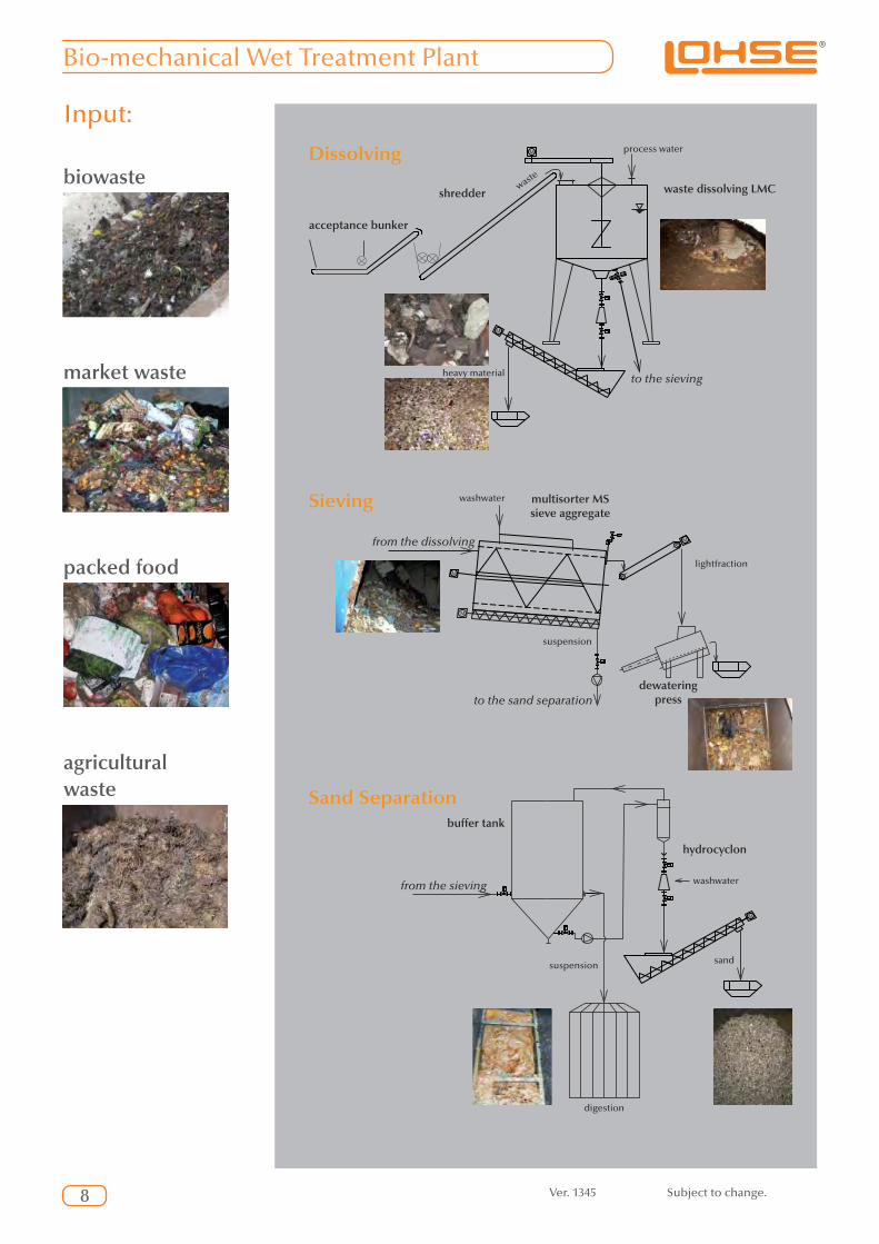
Dissolving M
M
waste dissolving LMCshredder
acceptance bunker
process water
heavy material
waste
to the sieving
suspension
M
sand
buffer tank
hydrocyclon
from the sieving
digestion
Sand Separation
Sieving
M
dewateringpress
M
M
multisorter MSsieve aggregate
to the sand separation
lightfraction
suspension
from the dissolving
washwater
washwater
Input:
biowaste
market waste
packed food
agricultural waste
Bio-mechanical Wet Treatment Plant

H2
H1
®
Mechanical Engineering
Maschinenbau Lohse GmbHUnteres Paradies 63 · 89522 HeidenheimPostfach 1565 · 89505 Heidenheimphone +49(0)7321 / 755-79 · fax +49(0)7321 / [email protected] ·www.lohse-gmbh.de
11111111111111HHHHHHHHHHHHHHHHHHHHHHHHHHHHHHHHHHHH
Waste Pulper LMCfor production of pumpable suspensions

Subject to change.10
®
Ver. 1444
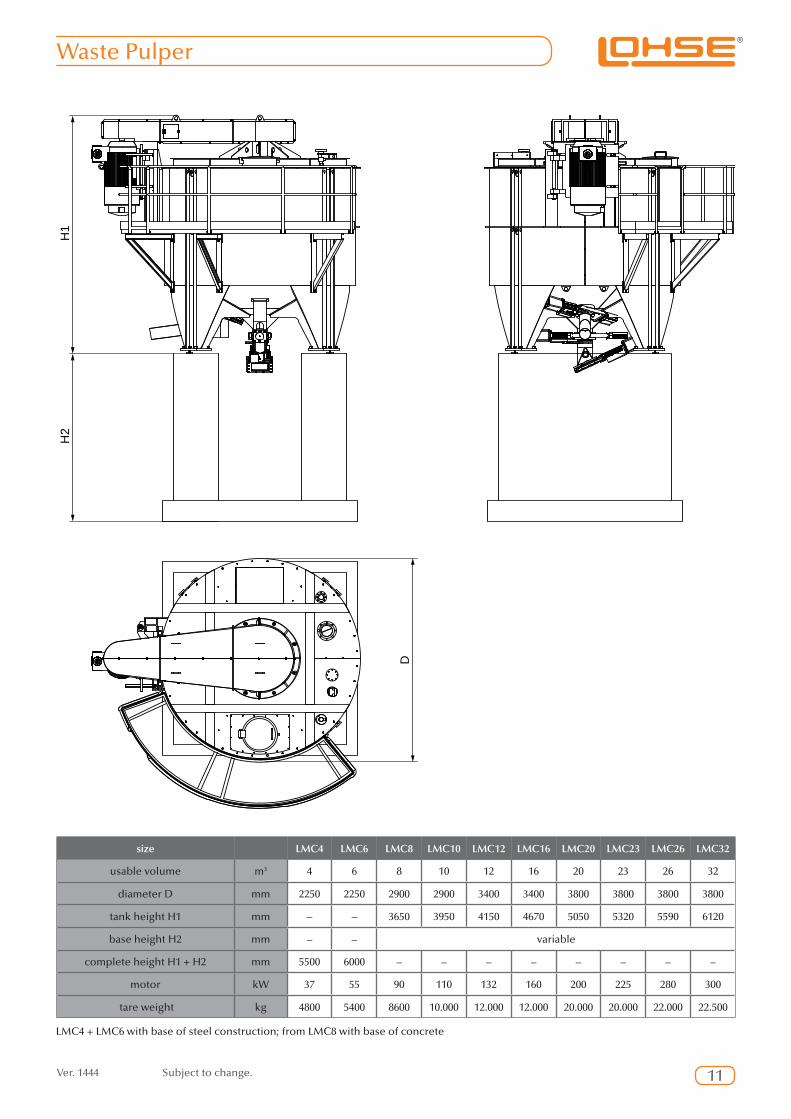
Waste Pulper
Waste pulper serve to separate a pumpable medium from organic waste and water. The waste is pulped and dissolved in the waste pulper. By means of a hwavy materials dirt trap the rejected materials are separated from the accepted medium.
Application
Design • stable bearing assembly on the top • closed tank • centrically positioned dirt trap • pulping tackle with removable wear parts • components to optimize the dispersing process • spiral conveyor to remove the heavy rejected materials
proc
ess
wat
er
disperger disc
drive
M
waste
sand andheavy rejects
sand and heavy materialtrap
M
accepts
Subject to change. 11
®
Ver. 1444
Waste PulperH
2H
1
D
size LMC4 LMC6 LMC8 LMC10 LMC12 LMC16 LMC20 LMC23 LMC26 LMC32
usable volume m3 4 6 8 10 12 16 20 23 26 32
diameter D mm 2250 2250 2900 2900 3400 3400 3800 3800 3800 3800
tank height H1 mm – – 3650 3950 4150 4670 5050 5320 5590 6120
base height H2 mm – – variable
complete height H1 + H2 mm 5500 6000 – – – – – – – –
motor kW 37 55 90 110 132 160 200 225 280 300
tare weight kg 4800 5400 8600 10.000 12.000 12.000 20.000 20.000 22.000 22.500
LMC4 + LMC6 with base of steel construction; from LMC8 with base of concrete

Subject to change.12
®
Ver. 1444
Waste Pulper
LMC4 + LMC6 with base of steel construction from LMC8 with base of concrete

H
®
Mechanical Engineering
Maschinenbau Lohse GmbHUnteres Paradies 63 · 89522 HeidenheimPostfach 1565 · 89505 Heidenheimphone +49(0)7321 / 755-79 · fax +49(0)7321 / [email protected] ·www.lohse-gmbh.de
H
Multisorters MSfor separation of impurities from suspensions

Subject to change.14
®
Ver. 1450
Multisorters
Multisorters are used to separate lightweight foreign materials from a suspensi-on consisting of recycled paper or organic waste in water.In the multisorter the suspension is fi ltered by means of a vertical screen; the foreign materials are discharged separately. In addition, the foreign materials can be rinsed very effectively.
Application
Design • closed tank • fi xed screen plate • slowly rotating cleaning arms for cleaning the screen plate • spiral conveyor for preventing sedimentation • 2-part housing for better maintenance and assembly capability • replacement of the screen without removing the rotor
M
M
Multisorter MSSieve Aggregate
cleaned suspension
light-fraction
input
wash wateroutlet valve

Subject to change. 15
®
Ver. 1710
Multisorters
L
H
B
size MS3 MS6 MS10 MS14
usable volume m3 3 6,5 9,6 13,8
diameter of sieve mm 1350 1800 2200 2500
length L mm 3650 4400 4800 5260
width B mm 1660 2170 2420 2720
overall height H mm 3250 4700 5150 5320
drive motor kW 7,5 18,5 30 37
tare weight kg 3800 4800 5600 7000

Subject to change.16
®
Ver. 1450
Multisorter

®
Mechanical Engineering
Maschinenbau Lohse GmbHUnteres Paradies 63 · 89522 HeidenheimPostfach 1565 · 89505 Heidenheimphone +49(0)7321 / 755-79 · fax +49(0)7321 / [email protected] ·www.lohse-gmbh.de
Mechanical Engineering
Rejectorto purify and disintegrate the raw suspension

Subject to change.18
®
The rejector is used as a sieving machine and serves to purify and disintegrate the raw suspension from waste pulping units or storage containers.
Rejector
Application
Advantages
Main components using the example of type F04
Rejector casing
Sieve case with bearing and breaker rotor
Helical gear box
Coupling
Slinding carriage to cange sieve and breaker rotor for maintenance
Support frame
Input slide valve (LOHSE CNAP)
Discharge slide valve for light fraction (LOHSE CDSP)
Discharge slide valve for sus-pension (LOHSE CNAP)
Construction and function
The raw suspension is intermittently fed to the centre of the rejector. The rejec-tor is a closed cylindrical container with a central disintegrator wheel to which a sieving unit is fl ange-mounted.The disintegrator wheel installed in the container causes a pronounced rotati-onal movement, which causes a disintegration of the raw suspension. The raw suspension which has been thus disintegrated fl ows through the sieve unit and is extracted by means of an upstream pump. Particles which are larger than the perforations of the sieve remain in the container and are held back. After a time, which can be adjusted, the foreign particles in the container be-come more concentrated. By the addition of fl ushing water, the fraction of for-eign particles remaining in the container (material to be sieved) is washed out.After this, by opening a slide valve which is attached to the base of the container by means of a fl ange, the remaining contents in the container (the foreign par-ticles) are removed from the rejector. Once the material to be sieved has been removed from the rejector, a new cycle begins. Foreign bodies (cutlery, steel parts, stones, textiles, plastic fi lm etc) remain in the container and are not forced through the sieve.
• less cost for wearing parts. • lower energy consumption • simple adaptation to various types of waste • prevention of clogging of the following units due to clogging of rotating parts
(macerator, agitators, etc.) • possibility by washing the contaminants more organic material in the fermen-
tation suspension • low content of organic matter in the contaminant fraction • low level of contaminants in the fermentation suspension due to gentle
screening • minimize the formation of fl oating debris by separating the light contami-
nants in the rejector
Ver. 1827
R
Sa
H
C
Ssm
S
IC
Df
Dp

Subject to change. 19
®Rejector
Ver. 1827
Function using the example of type F04
• Mailing of the raw suspension coming from the pulper or acceptance tank • Separation the light fraction from raw suspension (plastic, wood, textiles) and
other rest impurities (bones, metal, stones) • Particlesize in accordiance with hygienisation rules, stock preparation
Input
Light fractionSuspension
Breaker rotor
Screen plate
wash water
Process water

Subject to change.20
®
Ver. 1611
Rejector
Type F04 F10 P20
Throughput paper pulp TS 4-6% m³/h 18 48 100
Throughput leftover TS 8-12% m³/h 3 10 –
Useable volume tank dm³ 180 1000 2000
Tank diameter mm 650 1200 1500
Impeller diameter mm 410 950 960
Intake nozzle mm DN 125 DN 250 DN 350
Accepted stock nozzle mm DN 100 DN 20 DN 350
Reject discharge light fraction mm – DN 300 DN 250
Reject discharge light and heavy fraction mm DN 250 DN 300 DN 400
Flush water nozzle mm DN 50 DN 50 –
Speed impeller 1/min 555 322 at 50 Hz 380
AC motor kW 22/30 45 90
Material tank 1.4571 1.4571 1.4571
Material support, frame(not in touch with medium)
S235JR painted
St 37-2painted St 37-2
Operating weight (fi lled) kg approx. 1700 approx. 4000 approx. 9500
Tare weight kg approx. 1400 approx. 3100 approx. 7500
Technical data

F
14
1 4
®
Mechanical Engineering
Maschinenbau Lohse GmbHUnteres Paradies 63 · 89522 HeidenheimPostfach 1565 · 89505 Heidenheimphone +49(0)7321 / 755-79 · fax +49(0)7321 / [email protected] ·www.lohse-gmbh.de
Spiral Conveyors
F
14
4

Subject to change.Ver. 103622
®Spiral Conveyors
Spiral conveyors are suitable for transporting various materials. The shaftless design allows dry and wet, coarse and fi ne-particle, homogenous and inhomo-geneous materials to be conveyed.
Application
Construction • U-shaped stainless steel tub including stiffeners for high rigidity • screwed cover over U-shaped tub • shaftless S355 stainless steel conveyor spirals • wear resistant, stainless steel strip or plastic panel coating of U-shaped tub • conveyor spirals supported on one side • commercial fl anged geared motor with hollow shaft • optional sealing of drive shaft by stuffi ng box packing • optional drainage area • optional receiver tank for separation of sediments.
Individual application of spiral conveyors for transport is feasible in some indus-tries. A spiral conveyor must therefore designed for ist application.
type inside width vat [mm] Ø spiral[mm]
U 200 200 160
U 320 320 280
U 500 500 460
U 600 600 530
Other sizes on re-quest.
Standard sizes
U 320
U 500
U 600
644
ca.344
1452
.5
ca.45~
ca.33
6
4
Entlueftungsanschluss R1" IG ventilation connection R1" IG
14
34
14
35
33
18
21
36
16
6
®
Mechanical Engineering
Maschinenbau Lohse GmbHUnteres Paradies 63 · 89522 HeidenheimPostfach 1565 · 89505 Heidenheimphone +49(0)7321 / 755-79 · fax +49(0)7321 / [email protected] ·www.lohse-gmbh.de
Hydrocyclone,Dirt Trap andSand Classifi er
Sand Separators

Subject to change.24
®Sand Separators
Sand separators are used for heavy contaminant separation from suspensions. Wire and pieces of metal sheet, in particular small, grainsize particles, such as glass and grit, will be separated.
Application
Construction
Ver. 1541
• Hydrocyclone: • Headpiece including inlet and outlet pipes provided with wear-resistant
inserts • Separating cone with wear-resistant insert • Intermediate pipe
• Dirt trap: • Two pneumatically operated special gate valves • Flush valve
• Sand classifi er: • Box • Spiral conveyor
Operation The suspension entering the head-piece in tangential direction is subjected to high centrifugal acceleration based on the hydrocyclone principle. Under the effect of this, contaminants are fl ung to the wall of the separating cone, from where they sink into the dirt trap through an intermediate pipe, followed by the clean suspension being discharged from the headpiece of the grit separator in axial direction. Two looking glasses have been provided in the dirt trap for che-cking the sinking process. Heavy contaminants, such as adhering fi brous partic-les, are removed by the addition of backfl ow water to the dirt trap. Adjustable operating cycles of gate valves and dirt trap guarantee high adaptability to any level of contamination in the suspension.

Subject to change. 25
®
Ver. 1414
Sand Separators
Sand separator
Console
Frame
Dirt trap
Sand classifi er:
Box to sand classifi er
Spiral conveyer Support
Sand separator:
Discharge pipe
Cyclone head piece
Adapter long
Adapter short
Discharge plate pipe
Sight glass tubes
Dirt trap:
Upper dirt trap valve
Dirt trap body with fl ush valve
Lower dirt trap valve
Sand discharge

Subject to change.26
®
Ver. 1731
Sand Separators
type 160K 160T 200K 200T 250K 250T
throughput [l/min] 600 500 950 800 2000 1800
pressure loss [bar] 0,5 – 1,0 0,5 – 1,0 2,0 2,0 2,0 0,8 – 1,2
consistency [% of weight] 2 – 8 2 – 20 2 – 5 2 – 20 2 – 8 2 – 20
outlet Ø [mm] 50 50 50 50 100 100
inlet Ø [mm] 80 80 80 80 125 125
trap Ø [mm] 100 – 250 100 – 250 100 – 250 125 – 250 125 – 250 125 – 250
particle size [mm] < 20 < 20 < 30 < 30 < 30 < 30
length L [mm] 5000 5000 5000 5000 5000 5000
width B [mm] 2400 2400 2400 2400 2400 2400
height H [mm] 4150 4150 4570 4300 4300 4500
height of throw-off A [mm] 2070 2070 2070 2070 2070 2070

DN100
FüllwasserR1"
l
®
Mechanical Engineering
Maschinenbau Lohse GmbHUnteres Paradies 63 · 89522 HeidenheimPostfach 1565 · 89505 Heidenheimphone +49(0)7321 / 755-79 · fax +49(0)7321 / [email protected] ·www.lohse-gmbh.de
of stainless steelDirt Traps RSL
DDDDDDDDNDDDDDDNDNDDDDDNDNDDNDDNDDDNDDDDDDNDNDNDDDDDDNDNNDDDDDDDDDDDDDDDD
FFülFüFFüFülFülFülülülülFüFülülFülFFüFüFüFülFülülF lüFüFFülüFFFülüüüllFFüFFFüFüüülFüFFFFFFüüüFüFüFülFüFFüüFülFFFülüllFüüülFFülülFFüllFülFF lwalwalwalwalwawalwawwallwalwalwwalwawalwlwwlwwlwlwlwlwwlwlwwlwlwwlwalwwwlwlwwlwalwlwwalwwwwwawwww ssessessessesesessessessesseeseeess eeeeess eeesseeeees errrrrrrrrrrrrrrrrrrrrrrrrrrR1"R1"R1"R1"R1"R1"R1"R1"R1"RR1"RR

Subject to change.28
®RSL
The LOHSE dirt traps RSL have been specially designed for the removal of for-eign particles from the cleaning process.
They are used to remove reject particles from fi brous media of various viscosity. They can be used in all types of cleaning machines, tanks and pipelines.
The maximum permissible operating temperature for LOHSE RSL dirt traps is 80 °C / 176° F (dirt traps for higher temperatures are available on request).
The maximum permissible operating pressure for LOHSE RSL dirt traps is 6 bar (dirt traps for higher pressures are available on request).
Applications
pulp and paper production
waste technology
high proportion ofreject parts
Media
• he inclined positioning of the dis-charge valve prevents the build up of tur-bulence in the centre of the valve slide plate; as a result there is markedly less wear on the valve slide plate
• the right angular cross section of the discharge valve prevents small parts getting stuck between the valve body and the slide plate
• two back water connections prevent congestion in dead corners • regulated heavy rejects removal: by means of 2 sight glasses an optimal ad-
justment of the back water level becomes possible • pressure relief when at its highest level by means of an air extraction connec-
tion • dirt trap volume can be selected (see list)
Benefi ts
Ver. 1403
Dirt Traps

Subject to change. 29
®Dirt TrapsRSL
Construction
pos. description remark
1 inlet valve CDSVP/G round cross-section
2 sluice chamber round to rectangular
3 discharge valve AEQP/G rectangular cross-section
4 sight glasses
5 air relief C periodical operating interval
6 cleaning/ fi lling connections A / B periodical operating interval
7 fl ush water connection D connection recommende by manufacturer
8 fl ush water connection E connection recommende by manufacturer
9 attaching device
10 outlet piece
Ver. 1546
1
3
2
4
5
6
7
8
9 10

Subject to change.30
®
Process description
Start of dirt trap controlPower to solenoid valves „on“Water pressure „ok“Water „supply ok“Pump of cleaning machine „off“Compressed air for shut-off valve „supply ok“- Pressure „ok“- Flow control valve „adjusted“
START – Flushing phase of dirt trapThe moment the pump in front of the cleaning machine is started, the timer relay of the cycle control system is started. After the cycle time has lapsed:
- Timer relay cycle time „0“- Upper shut-off valve „closed“- Lower shut-off valve „open“- Filling water solenoid valve „open“- FILLING timer relay „on“ (10 to 20 sec.)- Signal lower valve „closed“ via exhaust air restrictor- VENTING timer relay „on“ (10 to 20 sec.)- Signal lower valve „closed“- FILLING timer relay after time has lapsed „off“- Filling water solenoid valve „closed“- VENTING timer relay after time has lapsed „off“- Air relief solenoid valve „closed“- Upper shut-off valve „open“If required: - Readjustment of dilution water by means of manually operated taps- Next cycle time started through timer relay „on“ (5 to 120 minutes)
* All values are approximate and must be adapted to the specifi c system!
Interlocking:if there is no compressed air if there is no dilution waterif there is no control voltageif there is no mediumif the medium pressure drops in front of the cleaning machine
RSL
Ver. 1403
Dirt Traps

Subject to change. 31
®
TypeInlet valve
Reject-valvetype CDSVP/G
Outlet valveReject-valve
type AEQP/G
Volume [l]
Overall height [mm]
Air relief C[inch]
cleaning/ fi lling connections A / B
[inch]
fl ush water connect. D
[inch]
fl ush water connect. E
[inch]
RSL 50/150 DN 50 DN 150 ~ 5 682 1/2 1/2 1 3/4
RSL 65/150 DN 65 DN 150 ~ 5 682 1/2 1/2 1 3/4
RSL 80/150 DN 80 DN 150 ~ 5 695 1/2 1/2 1 3/4
RSL 100/150 DN 100 DN 150 ~ 8 635 1 3/4 1 3/4
RSL 100/200 DN 100 DN 200 ~ 11 650 1 3/4 1 3/4
RSL 100/250 DN 100 DN 250 ~ 15 634 1 3/4 1 3/4
RSL 125/250 DN 125 DN 250 ~ 15 635 1 3/4 1 3/4
RSL 150/200 DN 150 DN 200 ~ 13 660 1 3/4 1 3/4
RSL 150/250 DN 150 DN 250 ~ 17 662 1 3/4 1 3/4
RSL 200/250 DN 200 DN 250 ~ 22 745 1 3/4 1 3/4
RSL 250/300 DN 250 DN 300 ~ 40 823 1 3/4 1 3/4
Technical data
Outlet valve of cast iron (G) or stainless steel (E).
Dirt TrapsRSL
Ver. 1546
C
E
D
A/B

Subject to change.32
®RSL
Ver. 1403
Dirt Traps

®
Mechanical Engineering
Maschinenbau Lohse GmbHUnteres Paradies 63 · 89522 HeidenheimPostfach 1565 · 89505 Heidenheimphone +49(0)7321 / 755-79 · fax +49(0)7321 / [email protected] ·www.lohse-gmbh.de
RBrr and RBrqVortex Breakers

Subject to change.34
®
Ver. 1405
Applications In case of extreme wear on reject valves / dirt traps, e.g. high density cleaners.
The rectangular cross section slows down the rotation of the medium and the rotation does not penetrate to the valve.
RB Vortex Breakers
Vortex breakers for heavy component dirt traps
Function
Rotation intensity
without vortex breaker with vortex breaker
Ready-to-install intermediate component on cleaning machines
Subject to change. 35
®
Ver. 1405
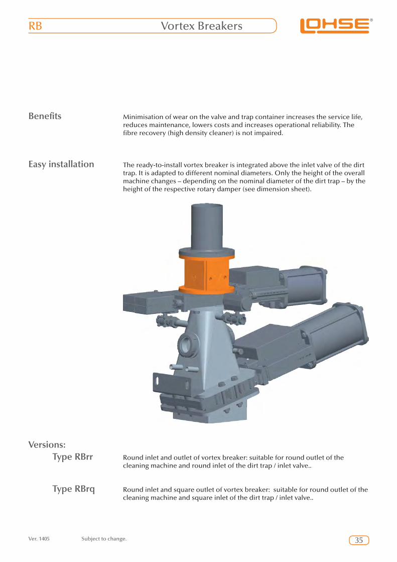
Benefi ts
Easy installation
Versions: Type RBrr Round inlet and outlet of vortex breaker: suitable for round outlet of the
cleaning machine and round inlet of the dirt trap / inlet valve..
Round inlet and square outlet of vortex breaker: suitable for round outlet of the cleaning machine and square inlet of the dirt trap / inlet valve..
Minimisation of wear on the valve and trap container increases the service life, reduces maintenance, lowers costs and increases operational reliability. The fi bre recovery (high density cleaner) is not impaired.
The ready-to-install vortex breaker is integrated above the inlet valve of the dirt trap. It is adapted to different nominal diameters. Only the height of the overall machine changes – depending on the nominal diameter of the dirt trap – by the height of the respective rotary damper (see dimension sheet).
Type RBrq
RB Vortex Breakers

Subject to change.36
®Vortex BreakersRBrr
Dimensions in mm, fl ange dimensions to DIN EN 1092-1, PN 10.Further sizes on request.
Ver. 1705
DN A B G S H ØD
50 25 43 1/4“ 13 110 165
80 50 53 1/2‘‘ 13 120 200
100 60 63 1/2‘‘ 17 150 220
125 80 63 1/2‘‘ 17 175 250
150 100 73 1/2‘‘ 17 190 285
200 150 74 1/2‘‘ 18 220 340
250 200 74 1/2“ 18 260 395
350 250 74 1/2‘‘ 23 350 505
threaded hole
through holeflush connection
SS
H
A
B
DN
ØD
DN
G
Material: 1.4571
Subject to change. 37
®
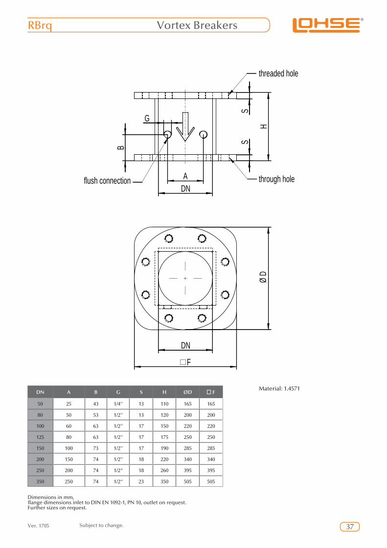
Dimensions in mm, fl ange dimensions inlet to DIN EN 1092-1, PN 10, outlet on request.Further sizes on request.
Vortex BreakersRBrq
threaded hole
through holeflush connection
DN
Ø D
ADN
SS
H
GB
F
Material: 1.4571DN A B G S H ØD F
50 25 43 1/4'' 13 110 165 165
80 50 53 1/2'' 13 120 200 200
100 60 63 1/2'' 17 150 220 220
125 80 63 1/2'' 17 175 250 250
150 100 73 1/2'' 17 190 285 285
200 150 74 1/2'' 18 220 340 340
250 200 74 1/2“ 18 260 395 395
350 250 74 1/2‘‘ 23 350 505 505
Ver. 1705

38
®

656
602
513
2250
Ø 23
70°
DN
150
®
Mechanical Engineering
Maschinenbau Lohse GmbHUnteres Paradies 63 · 89522 HeidenheimPostfach 1565 · 89505 Heidenheimphone +49(0)7321 / 755-79 · fax +49(0)7321 / [email protected] ·www.lohse-gmbh.de
Dewatering Presses22
5022
5022
5022
50 70°
DN
1

Subject to change.40
®
Ver. 1603
409
1516
120
980
1120
120
20
3569
3186
2210
220
ca. 4163
n23
1256
1327
2601
2002
16082556
543973
1103
B
L
1145
1307
DN100
middle of feed channel
protection guardsplash guard cover
feed channel slot B x L
Dewatering Presses
Dewatering press for dewatering reject from the waste paper pulpers. Plastic or metal wires are cut at the same time when dewatering process takes place. The pressed waste will be set out by a valve.
Its simple structure allows uninterrupted operation. Low follow-on costs due to few and simple replaceable wear parts.
Application and function
technical data LP03 LP07
cutting power [kN] 700 700
spec. pressure [bar] 58 29
dimension of punch area [mm] 400 x 300 800 x 300
opening of inlet [mm] 400 x 600 800 x 600
required power hydraulic unit [kW] 9,2 9,2
motor [kW] 11 11
oil pressure [bar] 220 220
weight [kg] 4000 4200
throughput [m³/h] 3 – 4 7
dry content [%] 40 – 60 40 – 50
®
Mechanical Engineering
Maschinenbau Lohse GmbHUnteres Paradies 63 · 89522 HeidenheimPostfach 1565 · 89505 Heidenheimphone +49(0)7321 / 755-79 · fax +49(0)7321 / [email protected] ·www.lohse-gmbh.de
for the Waste Technology
Mounting and Service

Subject to change.42
®
Ver. 1342
Mounting and Service Waste Technology
Maschinenbau Lohse GmbH develops, builds and delivers bio-mechanical wet processing systems for biowaste, food scraps and residual waste - and has done so for more than 25 years.
As the result of many years of cooperation with our customers we specialise in treatment technology for various types of organic waste (e.g. biowaste, market waste, packaged foods, agricultural waste, etc.) for wet fermentation. We offer customised complete solutions with advanced, time-tested technology and can provided numerous references.
With this expertise we can offer the optimal and therefore most economical solution for diverse problems involving wear.
Our own design department and modern mechanical treatment department with an extensive machine park guarantee fast, fl exible and reliable implementa-tion.
More and more industrial enterprises are benefi ting from being able to concen-trate purely on production. We help them to achieve this. The maintenance of technological production systems requires extensive knowledge of individual systems as well as familiarity with the production processes. Our maintenance service includes troubleshooting and repairs, adjustments, changing of process materials and replacement of wear parts.
• waste pulpers • multiple sorters • sieve drums • conveyor systems • sand separators • outward transfer devices • reject presses • subsurface waste bins
We perform repairs and maintenance for the following waste technology:
In addition, we perform wage labour:construction · cutting to size · rolling · edging · welding · metalworking, sand-blasting · pickling · turning · milling · drilling · punching, etc.various assembly work
Technological production maintenance:

®
Mechanical Engineering
Maschinenbau Lohse GmbHUnteres Paradies 63 · 89522 HeidenheimPostfach 1565 · 89505 Heidenheimphone +49(0)7321 / 755-79 · fax +49(0)7321 / [email protected] ·www.lohse-gmbh.de
for Waste Paper Pulpers
Raking Systems

Subject to change.44
®
Ver. 1042
Raking Systems for Waste Paper Pulpers
The suspension that rotates in the pulping process in the waste paper pulper spins the contrary material that came in with the waste paper, such as, e.g. wires, fi lms, plastic and insoluble paper, into a rope. If only smaller disconnected ropes are formed, so that raking using a rope winch is very complicated, we recommend using Lohse raking systems, which can be adapted to the respective operations (periodic or continuous).
The system consists of a tried and tested basic unit, which can be combined with three different collecting devices.
suitable for extracting contrary material that does not twist into a rope during the pulping process
suitable for extracting contrary material that twists into short rope lengths du-ring the pulping process
suitable for extracting short rope lengths and short, non-roping contrary materi-al
Type R (rake)
Type K (combination)
Type H (hook)
The stand-alone appliance is fastened to the fl oor next to the waste paper pulper. A discharge station (chute or funnel) into a transport container must be installed in the swivelling radius of the collecting arm, which runs contrary to the direction of the waste paper pulper. When at a standstill the swung out collecting arm stops above the discharge station.A cleaning cycle is initiated when the waste paper pulper is pumped off and the residual suspension in the tank has been diluted back down to a material densi-ty of 1.5% to 3% with the required process water for the next pulping process.A hydraulic rotary actuator swings the collecting device from its starting position into the collecting position above the waste paper pulper. Two hydraulic lifting cylinders lowers the collecting arm into the waste paper pulper in its collecting position, where it remains for a period determined in experiments. On expiry of this dwell time the collecting arm is lifted out of the waste paper pulper and stops above the waste paper pulper for a defi ned draining period. The loaded collecting device then swings out over the edge of the waste paper pulper to the discharge station. Here a hydraulic rotary actuator turns the collecting arm so that the rejects fall out of the teeth. The collecting process can be repeated several times, depending on the contra-ry material.The control sequence can be carried out at an integrated electric switchgear cabinet in manual or in automatic mode.
Installation and function

Subject to change.Ver. 1036 45
®Raking Systems for Waste Paper Pulpers
size 1 2 3
dip in depth / waste paper pulper h [mm] <= 2700 <= 3300 > 3300
swinging distance r [mm] 2700 ... 3000
swinging angle [angle] 120
operation (depending of reject volume and pulpersize) periodic
interval time (depending of reject volume and pulpersize) adjustable by timer
diving time pulper [min.] 0,5 ... 1
total operation time [min.] 4
reject weight aprox. (balanced on waste paper mix B12 / B19)
type R (rake) ~ [kg] 20 ... 30 30 ... 40 40 ... 50
type H (hook) ~ [kg] 20 30 40
type K (combination) ~ [kg] 25 35 45
hook drive [kW] 1,5 2,2 3
swinging drive [kW] 2,2 3 4
hydraulic drive [kW] 7,5 11 15
height drive (rakearm in top position befor swinging) [mm] max. height 1800 above pulper top
basic dimensions a x b [mm] 1100 x 1500
place of installation beside pulper
Technical data
Type R Type H Type K

46
®

®
Mechanical Engineering
Maschinenbau Lohse GmbHUnteres Paradies 63 · 89522 HeidenheimPostfach 1565 · 89505 Heidenheimphone +49(0)7321 / 755-79 · fax +49(0)7321 / [email protected] ·www.lohse-gmbh.de
Rope Cutters

Subject to change.48
®
Ver. 1603
The suspension that rotates on the pulping process in the waste paper pulper spins the contrary material that came in with the waste paper, such as, e.g. wires, fi lms, plastic and insoluble paper, into a rope. This rope is drawn out of the waste paper pulper with a rope winch. The rope winch is driven with a suitably variable interval switching. Depending on the amount of contrary material in the waste paper to be processed, and on the size of the pulper, endless ro-pes with a diameter of between 150 mm and 500 mm are formed. For disposal purposes these ropes must be cut into transportable pieces. This is done with a Lohse rope cutter, which is installed behind the rope winch in such way that the rope emerging from the winch is led without force via a funnel into the cutting opening. Lengths very between 300 mm and 3000 mm, depending on customers‘ wishes.
The rope cutter consists of two cutter bars with four integrated reversing scissor blades, which are moved in the opposite direction to the middle of the scissors by means of a hydraulic cylinder. The rope is cut through without interrupting production and without an increased risk of accident.
The hydraulic cylinders are operated and the cutting procedure is controlled with an external hydraulic unit coordinated to the rope cutter. Manual or au-tomatic mode can be selected with a preselection switch. In manual mode the cutting procedure can be initiated at any time by pressing a switch at the switch-gear cabinet. Automatic mode is possible if the controller is integrated corres-pondingly with the waste paper pulper operations. If the waste paper pulper is switched off during a cutting procedure, this is carried out and the cutter bar then returns to the starting position.
Lohse rope cutters DW 700 - for a rope diameter up to 650 mm
Rope Cutters DW 700

Subject to change. 49
®
Ver. 1511
size DW 700
cut opening [mm] 700 x 700
hopper opening [mm] Ø 680
cutting force [kN] ca. 500
cutting time [sec.] ca. 130
cutting intervals (depending on ragger speed) adjusable by timer
hydraulic driver motor [kW] 5,5
hydraulic pressure max. [bar] 220
width [mm] 2000
height [mm] 890
length [mm] 2460
weight [kg] ca. 4800
Technical data
Rope Cutters DW 700

50
®

®
Mechanical Engineering
Maschinenbau Lohse GmbHUnteres Paradies 63 · 89522 HeidenheimPostfach 1565 · 89505 Heidenheimphone +49(0)7321 / 755-79 · fax +49(0)7321 / [email protected] ·www.lohse-gmbh.de
Reject Drums
Subject to change.Ver. 103652
®Reject Drums
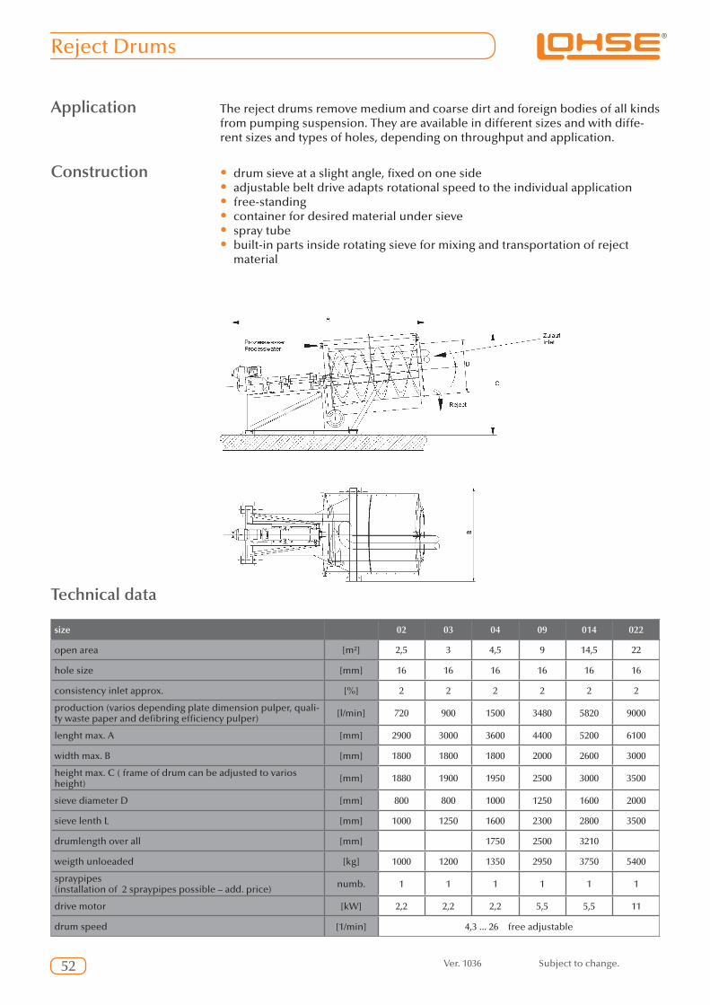
Construction • drum sieve at a slight angle, fi xed on one side • adjustable belt drive adapts rotational speed to the individual application • free-standing • container for desired material under sieve • spray tube • built-in parts inside rotating sieve for mixing and transportation of reject
material
Application The reject drums remove medium and coarse dirt and foreign bodies of all kinds from pumping suspension. They are available in different sizes and with diffe-rent sizes and types of holes, depending on throughput and application.
size 02 03 04 09 014 022
open area [m²] 2,5 3 4,5 9 14,5 22
hole size [mm] 16 16 16 16 16 16
consistency inlet approx. [%] 2 2 2 2 2 2
production (varios depending plate dimension pulper, quali-ty waste paper and defi bring effi ciency pulper) [l/min] 720 900 1500 3480 5820 9000
lenght max. A [mm] 2900 3000 3600 4400 5200 6100
width max. B [mm] 1800 1800 1800 2000 2600 3000
height max. C ( frame of drum can be adjusted to varios height) [mm] 1880 1900 1950 2500 3000 3500
sieve diameter D [mm] 800 800 1000 1250 1600 2000
sieve lenth L [mm] 1000 1250 1600 2300 2800 3500
drumlength over all [mm] 1750 2500 3210
weigth unloeaded [kg] 1000 1200 1350 2950 3750 5400
spraypipes(installation of 2 spraypipes possible – add. price) numb. 1 1 1 1 1 1
drive motor [kW] 2,2 2,2 2,2 5,5 5,5 11
drum speed [1/min] 4,3 ... 26 free adjustable
Technical data

b2
b1 AB
®
Mechanical Engineering
Maschinenbau Lohse GmbHUnteres Paradies 63 · 89522 HeidenheimPostfach 1565 · 89505 Heidenheimphone +49(0)7321 / 755-79 · fax +49(0)7321 / [email protected] ·www.lohse-gmbh.de
Type 500 K, Type 1000 K, Type 1000 SCH
Vibration Screensb2
111b1b1b1b1b1b111b1b1b1b11b1b1111111b1111111b1111b1b111b1111bbbbbbbbbbbbbbbbbb

Subject to change.Ver. 103654
®Type KVibration Screens
Due to the optional use of perforated and slotted sheets vibration screens are suitable for any grading tasks encountered in the paper industry, both in the low and high-density range.
Application
Construction • stainless steel or steel grading tub with protective rubber coating • screen basket supported by sprung stainless steel cross bars within the tub,
screen basket provided with a baffl e frame • waterproof enclosed unbalance support including permanently set unbalance
mass • easily replaceable perforated or slotted sheet screens • type B3 drive motor including an articulated shaft, adjustable baffl e fl ap for
back-up of accepts • spray pipe for fi brous return water • plastic folding canopy
The vibration screens is suitable for universal use. Due to its design and allowing the use of perforated or slotted sheets for grading, the grader is easily adjusted to any type of fi brous material.Due to fast removal of coarse screenings based on a relatively high vibration fre-quency of the screening basket and the chosen vibration amplitude being high-er than the maximum fi bre length encountered, smooth operation without any spinning or blocking will be feasible. Improved removal of coarse screenings by use of a baffl e fl ap below the screening sheet.Depending on the graded size, the pulp will pass through one or two inlets to-wards the screening basket. Screened coarse screenings are carried out through the screening basket projecting from of the grader. In order to support the gra-ding effect, accepts are dammed by an adjustable overfl ow fl ap within the tub. Overfl owing accepts will leave the grader by an aperture in the tub bottom. A spray pipe is used for back-washing of any good fi bres adhering to coarse screenings. The vibration screens is covered by a plastic canopy. This canopy and the screening basket may be easily folded up and/or removed for cleaning.
Operation

Subject to change. 55
®
Ver. 1611
Type KVibration Screens
l
e
h2
h1
b2
b1 AB
coarsescreenings
accepts
screening size 500 1000
low-density pulp screening pulp density throughput
[%][t/24h]
23 – 11
210 – 33
high-density pulp screening pulp density throughput
[%][t/24h]
2 – 4,55 – 23
2 – 4,515 – 65
AB (working width) [mm] ~ 500 ~ 1000
b1 [mm] 1040 1800
b2 [mm] ~ 1510 ~ 2450
e [mm] ~ 290 ~ 405
h1 [mm] ~ 710 ~ 910
h2 [mm] ~ 1480 ~ 2530
l [mm] ~ 1760 ~ 2510
engine power [kW] 1.1 1.1
empty weight [kg] 420 1300
Technical data

Subject to change.56
®
Ver. 1034
Type 1000 SCHVibration Screens
This robust vibration screen with a large screening area is used in wood grinding plants as a means to catch tailings and thus to separate the splinters and tailings from ground wood.
Application
Construction • stainless steel grading tub • screen basket supported by sprung stainless steel cross bars within the tub • waterproof enclosed unbalance support including permanently set unbalance
mass • easily replaceable perforated sheet screens • type B3 drive motor including an articulated shaft, adjustable baffl e fl ap for
back-up of accepts • spray pipe for fi brous return water
The vibration screen is suitable for universal use. Due to its design and allowing the use of perforated sheets for grading, the grader is easily adjusted to any type of fi brous material.Due to fast removal of coarse screenings based on a relatively high vibration fre-quency of the screening basket and the chosen vibration amplitude being high-er than the maximum fi bre length encountered, smooth operation without any spinning or blocking will be feasible. Improved removal of coarse screenings by use of a baffl e fl ap below the screening sheet.Depending on the graded size, the pulp will pass through one or two inlets to-wards the screening basket. Screened coarse screenings are carried out through the screening basket projecting from of the grader. In order to support the gra-ding effect, accepts are dammed by an adjustable overfl ow fl ap within the tub. Overfl owing accepts will leave the grader by an aperture in the tub bottom. A spray pipe is used for back-washing of any good fi bres adhering to coarse screenings. The screening basket may be easily folded up and/or removed for cleaning.
Operation

Subject to change. 57
®
Ver. 1611
Type 1000 SCHVibration Screens
coarsscreenings
accepts
throughput (depending on type and densitiy of pulp and on perforation of sheet screen) [t/24h] 60 ... 80
stock consistency [%] 2
perforation of sheet screen Ø [mm] 4 ... 6
usage of splash water [l/min] ~ 150
pressure of splash water min. [bar] 2
speed [1/min] 1500
engine power [kW] 3
empty weight [kg] 1300
Technical data

58
®

®
Mechanical Engineering
Maschinenbau Lohse GmbHUnteres Paradies 63 · 89522 HeidenheimPostfach 1565 · 89505 Heidenheimphone +49(0)7321 / 755-79 · fax +49(0)7321 / [email protected] ·www.lohse-gmbh.de
Safety Access Doors

Subject to change.Ver. 103660
®Safety Access Doors
The UVV (regulations for the prevention of industrial accidents) stipulates that vats and containers must have an opening at their deepest point with an inside diameter of at least 0.6 m that can be sealed tightly to safeguard against unautho-rised or accidental opening and which enables a rapid aeration or ventilation as well as safe access for actions such as the performance of maintenance, service or repair work.
The Lohse Safety Access Door (manhole cover) seals reliably and has been ins-pected by the mutual indemnity association (Berufsgenossenschaft).
Safety
Use
Materials
Our opening system provides safety and security:The opening of the seal occurs independent of unlatching. This prevents acci-dental opening of a possibly full container.
Our safety access door is extremely versatile and can be used • in pressure and vacuum environments • with round and rectangular containers made of steel, stainless steel and con-
crete
All parts coming in contact with the stored medium are made of DIN 1.4571 stainless steel. All parts not coming in contact with the medium, such as strengthening ribs and binders, are made of DIN 1.4301 stainless steel. The hand wheel is made of aluminium. Bushings and hinge bolts are made of cast copper. The concrete cast parts are made of DIN 1.4301 stainless steel.

Subject to change. 61
®
Ver. 1530
Safety Access Doors
nominal size A B C D E F R operating pressure
Ø 600 B4 1070 600 430 142 225 16 – max. 20m water column
Ø 600 S4 – 600 430 142 225 16 see information max. 20m water column
Model B4 Model S4
F
D
C
Ø A
Ø B
Ø E
C
Ø E
D
R
F
Ø B

62
®

®
Mechanical Engineering
Maschinenbau Lohse GmbHUnteres Paradies 63 · 89522 HeidenheimPostfach 1565 · 89505 Heidenheimphone +49(0)7321 / 755-79 · fax +49(0)7321 / [email protected] ·www.lohse-gmbh.de
Roller Boards
Subject to change.64
®
Ver. 1808
Roller Boards
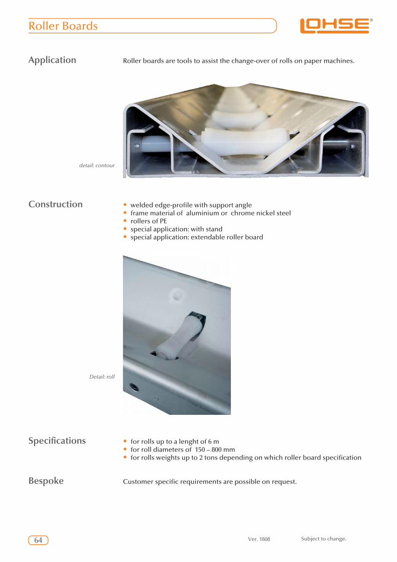
Roller boards are tools to assist the change-over of rolls on paper machines.Application
Construction
Specifi cations
Bespoke
• welded edge-profi le with support angle • frame material of aluminium or chrome nickel steel • rollers of PE • special application: with stand • special application: extendable roller board
• for rolls up to a lenght of 6 m • for roll diameters of 150 – 800 mm • for rolls weights up to 2 tons depending on which roller board specifi cation
Customer specifi c requirements are possible on request.
Detail: roll
detail: contour

®
Mechanical Engineering
Maschinenbau Lohse GmbHUnteres Paradies 63 · 89522 HeidenheimPostfach 1565 · 89505 Heidenheimphone +49(0)7321 / 755-79 · fax +49(0)7321 / [email protected] ·www.lohse-gmbh.de
on behalf of the customer
Construction and production

Subject to change.Ver. 103666
®Construction and production
For both new designs and the manufacture of steel and stainless steel products, pressure vessels, fans, machinery and equipment to existing plans, you have chosen the right partner in Maschinenbau Lohse GmbH.
We are working individually to your ideas or plans, design with the problem in mind, manufacture to your specifi cations, from prototypes to serial production.
Innovation, a high degree of technical know-how and many years of experience of committed employees will allow us to realise and supply your products within the shortest possible time.
Your ideas are in the right hands!
®
Mechanical Engineering
Maschinenbau Lohse GmbHUnteres Paradies 63 · 89522 HeidenheimPostfach 1565 · 89505 Heidenheimphone +49(0)7321 / 755-79 · fax +49(0)7321 / [email protected] ·www.lohse-gmbh.de
for the paper industryRepairs

Subject to change.Ver. 103668
®Repairs
• any type of pulper • vibration screens • perforated sheets with and without carrier frames • breaker rotors • helical breakers • any sorting machines and sizes including basalt linings • screening and soaking drums • centricleaners • heavy-item collecting bin on pulper • components for pressurised belt fi lter • steel and stainless steel structures • fans • pressure worms • various grades of hard coatings
The following repair and maintenance work will be performed for the paper industry:
In addition, we perform the following subcontract work:Design, cutting, rolling, edging, welding, locksmith work, grit-blasting, pickling, turning, milling, drilling, punching, etc. Range of assembly work.
For decades, Maschinenbau Lohse GmbH has been supplying fi xtures, appara-tus, vessels and ventilators for the paper and waste disposal industries.
As a supplier to the paper industry we have gained enormous experience in the problems of wear during many years of close cooperation with our customers. The knowledge thus gained has enabled us to supply the optimum and conse-quently most cost-effective solutions to the various problems of wear.
Our own design department and modern mechanical processing department with extensive machinery resources are the guarantees for a fast, fl exible and reliable processing of the jobs.
®
Mechanical Engineering
Maschinenbau Lohse GmbHUnteres Paradies 63 · 89522 HeidenheimPostfach 1565 · 89505 Heidenheimphone +49(0)7321 / 755-79 · fax +49(0)7321 / [email protected] ·www.lohse-gmbh.de
Pressure Tanksfor the industrial sector

Subject to change.70
®
Ver. 1528
In the fi eld of „custom-made products“, we regard ourselves as problem solvers. We produce custom-made pressure tanks and compressed-air tanks for your individual requirements.
Pressure Tanks
Pressure tanks made of steel plates or stainless steel in job production
Precision work We manufacture pressure tanks and compressed-air tanks according to custo-mer specifi cations:
• pressure tanks for air, nitrogen, water and argon up to PN 60 / 50°C • category III and IV tanks • heatable pressure tanks with double jacket • pressure tanks with driven quick-acting closures • pressure-loaded equipment, e.g. pipe sections • custom-made special tanks • accessories, e.g. fi ttings
All tanks are manufactured according to approved processes and formalities.
Subject to change. 71
®Pressure Tanks
Ver. 1528
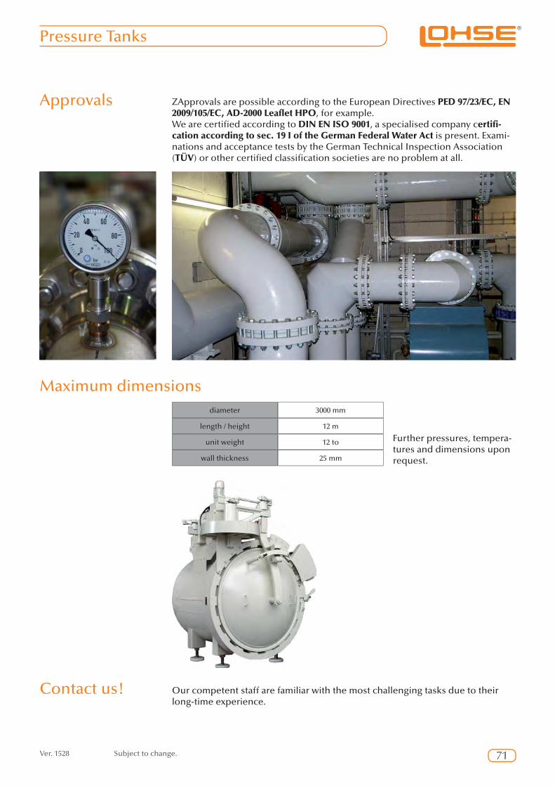
Approvals ZApprovals are possible according to the European Directives PED 97/23/EC, EN 2009/105/EC, AD-2000 Leafl et HPO, for example.We are certifi ed according to DIN EN ISO 9001, a specialised company certifi -cation according to sec. 19 I of the German Federal Water Act is present. Exami-nations and acceptance tests by the German Technical Inspection Association (TÜV) or other certifi ed classifi cation societies are no problem at all.
Maximum dimensionsdiameter 3000 mm
length / height 12 m
unit weight 12 to
wall thickness 25 mm
Further pressures, tempera-tures and dimensions upon request.
Contact us! Our competent staff are familiar with the most challenging tasks due to their long-time experience.

Subject to change.72
®Pressure Tanks

n 11.5
n 1043; z=24
7.1
7.2
7.3
7.4
®
Mechanical Engineering
Maschinenbau Lohse GmbHUnteres Paradies 63 · 89522 HeidenheimPostfach 1565 · 89505 Heidenheimphone +49(0)7321 / 755-79 · fax +49(0)7321 / [email protected] ·www.lohse-gmbh.de
Axial Fans
nnnnnnnnnnnnnnnnnnnnnnnnnnn 111.51111.1.1111 511111111
n 1043; z=24
7.27.2.27.27
7.33
77777.4.4477 44444444447 444444447 447 4

Subject to change.Ver. 103674
®Program M80Axial Fans
The fans will have impeller blades which can be adjusted, stepless during stand still.The axial fan program M 80 consists as a standard of 2 x 15 different sizes and arrangements, direct driven or belt driven.
Direktantrieb Keilriemenantrieb
400.250.6.A/M80 400.250.6.C/M80
500.315.6.A/M80 500.315.6.C/M80
630.315.6.A/M80 630.315.6.C/M80
630.400.6.A/M80 630.400.6.C/M80
800.500.8.A/M80 800.500.8.C/M80
800.315.6.A/M80 800.315.6.C/M80
800.250.6.A/M80 800.250.6.C/M80
1000.630.8.A/M80 1000.630.8.C/M80
1000.500.8.A/M80 1000.500.8.C/M80
1000.315.6.A/M80 1000.315.6.C/M80
1250.630.8.A/M80 1250.630.8.C/M80
1250.500.8.A/M80 1250.500.8.C/M80
1600.630.8.A/M80 1600.630.8.C/M80
1600.500.8.A/M80 1600.500.8.C/M80
2000.630.8.A/M80 2000.630.8.C/M80
Through direct drive the fan speed can be varied in the following steps:750 – 1000 – 1500 – 3000 rpm at 50 Hz / 900 – 1200 – 1800 – 3600 rpm at 60 Hz
Through belt drive a wider range of speed can be obtained. These variations give a wide working area for the axial fan M 80. lt is possible to obtain capacities from 360000 m3/h using fan 2000.630.8A/M 80 down to 1800 m3/h with the fan 400.250.6A/M 80. lt is further possible to obtain pressure up to 3600 Pa with the fan 800.500.8C/M 80.
A-drive (direct drive)
C-drive (belt drive)

Subject to change.Ver. 1036 75
®Program M80Axial Fans
Through work done in Voiths research laboratory, it has been possible to optimi-ze the profi le of the wings, which gives a very high effi ciency. In the medium pressure area effi ciencies up to 90%, and in high pressure areas 85% can be obtained. Taking into consideration todays high energy prices, these are very important factors when the pay back is considered.The technical design when manufacturing the fan housing and impellers gives the best results with regard to leakage losses between impeller and inlet cone. In that way it is possible to keep a high effi ciency.The complete unit with central tube, cables – and belt covers have an aerodyna-mic optimum design.With belt driven fans, it is possible as accessories instead of the cover which is located on the outlet of the central tube, to mount a rear piece which will be formed as an inside diffusor. In that way it is possible to regain part of the static pressure. A special inlet cone can be mounted on fans with open inlet, and the inlet loss will then be reduced. A special designed cover over the fan wheel hub ensures a best possible inlet air fl ow.
High effi ciency axial fan
A high effi ciency alone is not suffi cient to obtain a max. reduction in the total noise level. By reducing the amount of impeller wings, f. inst. from 12 to 8 or from 8 to 6, it is without doubt possible to fi nd a reduction in the sound pressu-re.The frequency based evaluation of the total sound pressure level at a given dis-tance in dB(A) based on the customers required working point, can be calcula-ted with a computer based on empiric measurements.
The axial fan with the low noise

Subject to change.Ver. 103676
®Program M80Axial Fans
Through several decades of experience in production of fans and other pro-cess equipment for the industry, we are aware of our responsibility with regard to safe operation for the equipment. The best material selection together with good craftsmanship is of great importance, whether the fan shall be installed in conjunction with a paper machine, for ventilation of large production areas or utilized in the offshore industry under servere conditions.Dependent on the design, the motor can be fl anged directly to the central tube and the fan impeller mounted directly on to the motor shaft. Using belt drive where the bearings and the shaft are mounted into the central tube, the central tube will be fi xed in the center of the fan housing through heavy gauge guide vanes.For obtaining a max. stability, heavy gauge materials are utilized. Fan requiring motor powers of 75 kW or above, has as a standard 5 mm sheet metal thickness. Flanges on fan sizes up to 1200 are at least 8 mm. For fan sizes 1250 up to 2000, a fl ange thickness of 12 mm will be used. The fl anges are fully welded to the fan housing.The fan impeller wings and hub are made in cast silumin G-A1 Si 10 Mg. Profi le thickness in the impeller wing is for example for a fan having a hub diameter of 630 mm up to 37 mm. This indicates the great stability of the fan impeller. An impeller for fan 1250.500.8 has a weight 59 kgs.
The axial fan having max. stability
The axial fan type M 80 will as a standard be delivered in St. 37.2, precoated and painted with a top coat. If required the fan can be supplied epoxy painted or hot dipped galvanized.In cases where there are special requirements with regard to corrosion resis-tants, the fan can be made in special corrosion resistant materials as aluminium or various grades of stainless steel. Does the fan operate in areas where conden-sation occurs, the impeller hub will be drained.Running at high temperatures and direct drive, the motor can be supplied with insulation class F. Using belt drive and at high temperature the bearings can be greased with high temperature grease.The fan can be delivered with brackets for vertical- or horizontal erection.
The axial fan having a max. fl exibility
The following accessories in various materials can be supplied: • inlet cone with protection grill • inlet- and outlet compensators • diffusor • mounting frames • epoxy painting • galvanizing
Accessories

®
Mechanical Engineering
Maschinenbau Lohse GmbHUnteres Paradies 63 · 89522 HeidenheimPostfach 1565 · 89505 Heidenheimphone +49(0)7321 / 755-79 · fax +49(0)7321 / [email protected] ·www.lohse-gmbh.de
Subcontract Work
Subject to change.78
®
Ver. 1325
Subcontract Work
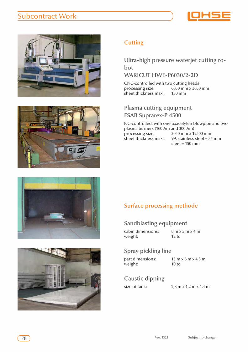
Surface processing methode
Sandblasting equipmentcabin dimensions: 8 m x 5 m x 4 mweight: 12 to
Spray pickling linepart dimensions: 15 m x 6 m x 4,5 mweight: 10 to
Caustic dippingsize of tank: 2,8 m x 1,2 m x 1,4 m
Cutting
Ultra-high pressure waterjet cutting ro-botWARICUT HWE-P6030/2-2DCNC-controlled with two cutting headsprocessing size: 6050 mm x 3050 mmsheet thickness max.: 150 mm
Plasma cutting equipmentESAB Suprarex-P 4500NC-controlled, with one oxacetylen blowpipe and two plasma burners (160 Am and 300 Am)processing size: 3050 mm x 12500 mmsheet thickness max.: VA stainless steel = 35 mm steel = 150 mm
Subject to change.Ver. 1036 79
®Subcontract Work
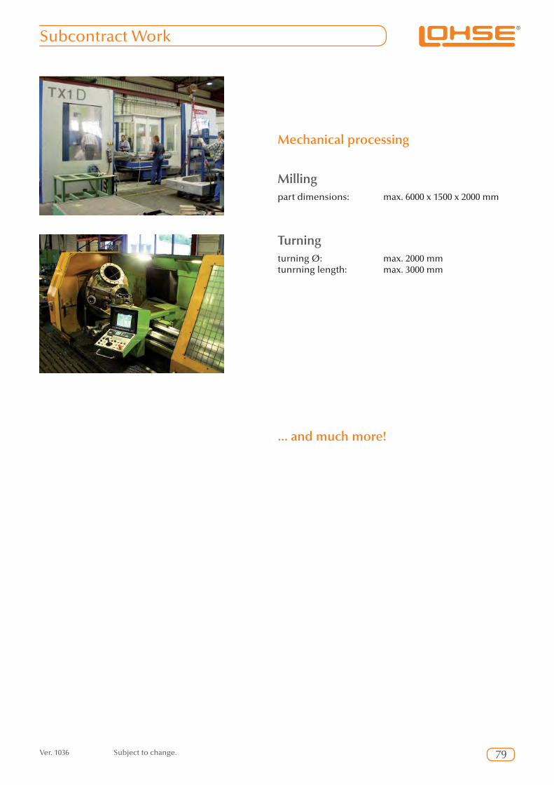
Mechanical processing
Millingpart dimensions: max. 6000 x 1500 x 2000 mm
Turningturning Ø: max. 2000 mmtunrning length: max. 3000 mm
... and much more!

80
®

Phone: +49(0)7321 / 755-79
Fax: +49(0)7321 / 755-93
E-Mail: [email protected]
Internet: www.lohse-gmbh.de
Maschinenbau Lohse GmbH
Unteres Paradies 63 · 89522 Heidenheim
Postfach 1565 · 89505 Heidenheim
Germany
®