PF Coils Quench Protection Design of EAST Superconducting Tokamak Oct. 5, 2005
Upload
myrtle-copelandCategory
view
214download
0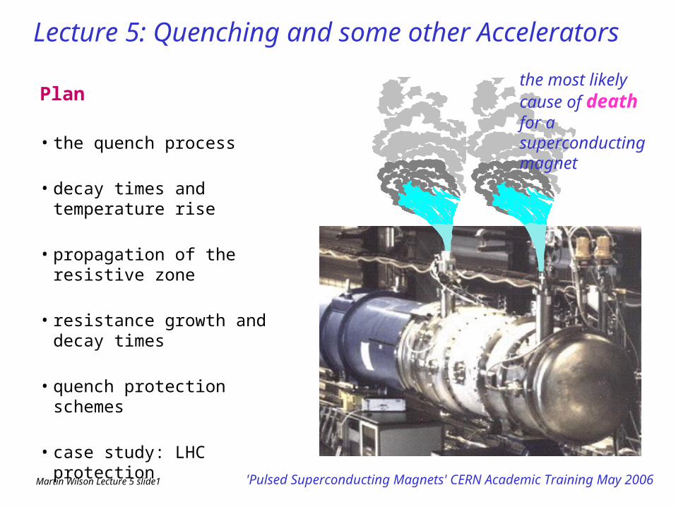
Martin Wilson Lecture 5 slide1 'Pulsed Superconducting Magnets' CERN Academic Training May 2006
Plan
• the quench process
• decay times and temperature rise
• propagation of the resistive zone
• resistance growth and decay times
• quench protection schemes
• case study: LHC protection
• pictures of superconducting accelerators
the most likely cause of death for a superconducting magnet
Lecture 5: Quenching and some other Accelerators
Martin Wilson Lecture 5 slide2 'Pulsed Superconducting Magnets' CERN Academic Training May 2006
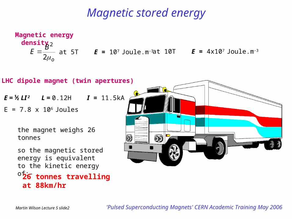
Magnetic stored energy
Magnetic energy density
o
BE
2
2
at 5T E = 107 Joule.m-3 at 10T E = 4x10⁷ Joule.m-3
LHC dipole magnet (twin apertures)
E = ½ LI 2 L = 0.12H I = 11.5kA
E = 7.8 x 10⁶ Joules
the magnet weighs 26 tonnes
so the magnetic stored energy is equivalent to the kinetic energy of:-
26 tonnes travelling at 88km/hr
Martin Wilson Lecture 5 slide3 'Pulsed Superconducting Magnets' CERN Academic Training May 2006
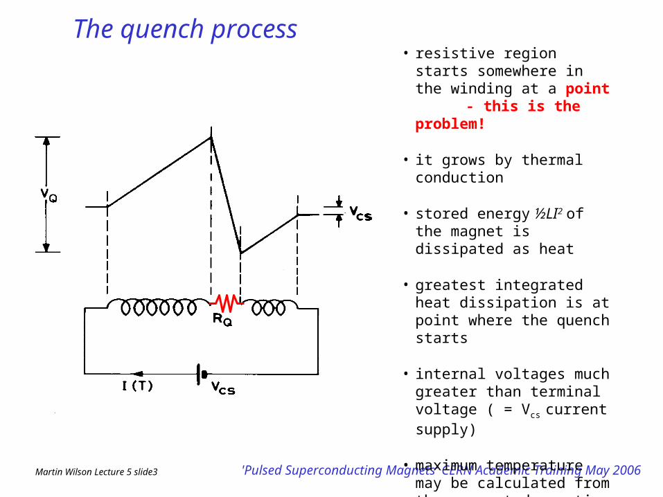
The quench process • resistive region starts somewhere
in the winding at a point - this is the problem!
• it grows by thermal conduction
• stored energy ½LI2 of the magnet is dissipated as heat
• greatest integrated heat dissipation is at point where the quench starts
• internal voltages much greater than terminal voltage ( = Vcs
current supply)
• maximum temperature may be calculated from the current decay time via the Ufunction (adiabatic approximation)
Martin Wilson Lecture 5 slide4 'Pulsed Superconducting Magnets' CERN Academic Training May 2006
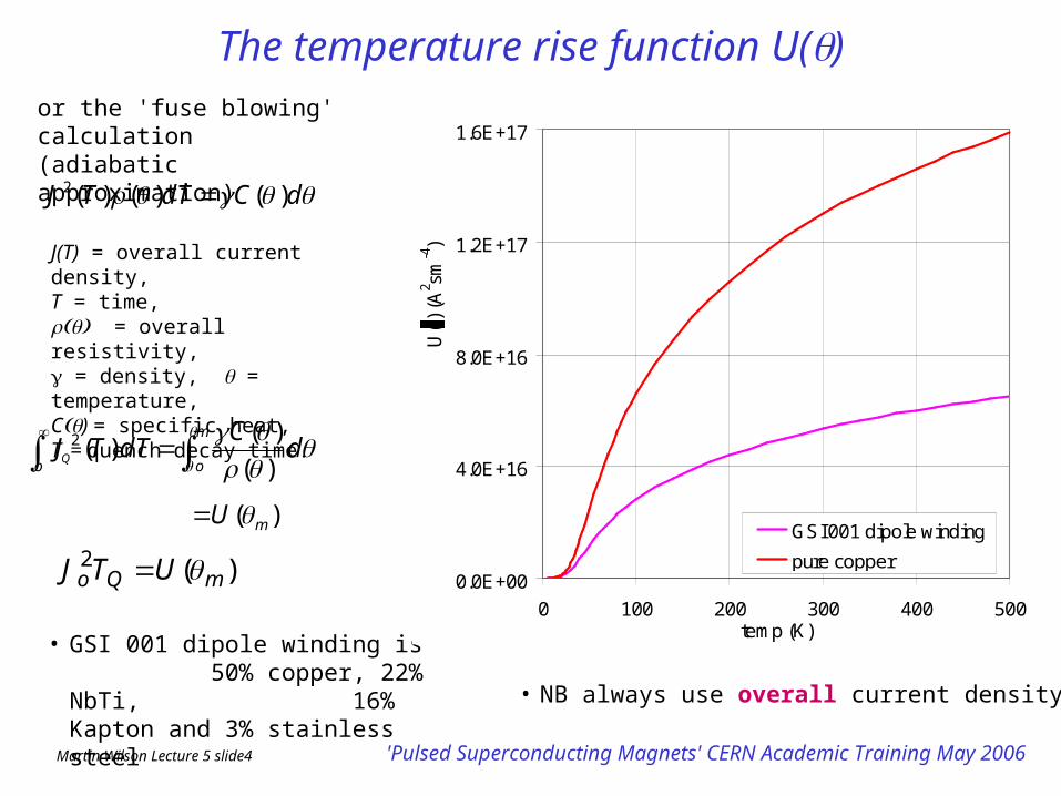
The temperature rise function U()
• GSI 001 dipole winding is 50% copper, 22% NbTi, 16% Kapton and 3% stainless steel
or the 'fuse blowing' calculation (adiabatic approximation)
dCdTTJ )()()(2
m
ood
CdTTJ
)(
)()(2
)(2mQo UTJ
)( mU
• NB always use overall current density
J(T) = overall current density, T = time, = overall resistivity, = density, = temperature, C) = specific heat, TQ= quench decay time.
0.0E+00
4.0E+16
8.0E+16
1.2E+17
1.6E+17
0 100 200 300 400 500temp (K)
U(
) (A
2 sm-4)
GSI 001 dipole winding
pure copper
Martin Wilson Lecture 5 slide5 'Pulsed Superconducting Magnets' CERN Academic Training May 2006
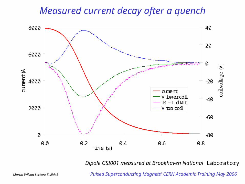
Measured current decay after a quench
Dipole GSI001 measured at Brookhaven National Laboratory
0
2000
4000
6000
8000
0.0 0.2 0.4 0.6 0.8time (s)
curr
en
t (A
)
-80
-60
-40
-20
0
20
40
coil
volta
ge (
V)
currentV lower coilIR = L dI/dtV top coil
Martin Wilson Lecture 5 slide6 'Pulsed Superconducting Magnets' CERN Academic Training May 2006
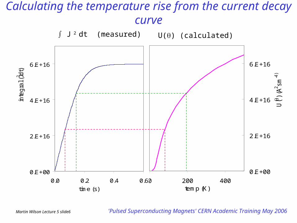
0.E+00
2.E+16
4.E+16
6.E+16
0 200 400temp (K)
U(
) (A
2 sm-4
)
Calculating the temperature rise from the current decay curve
0.E+00
2.E+16
4.E+16
6.E+16
0.0 0.2 0.4 0.6
time (s)
inte
gra
l (J2 d
t)
J 2 dt (measured) U() (calculated)
Martin Wilson Lecture 5 slide7 'Pulsed Superconducting Magnets' CERN Academic Training May 2006
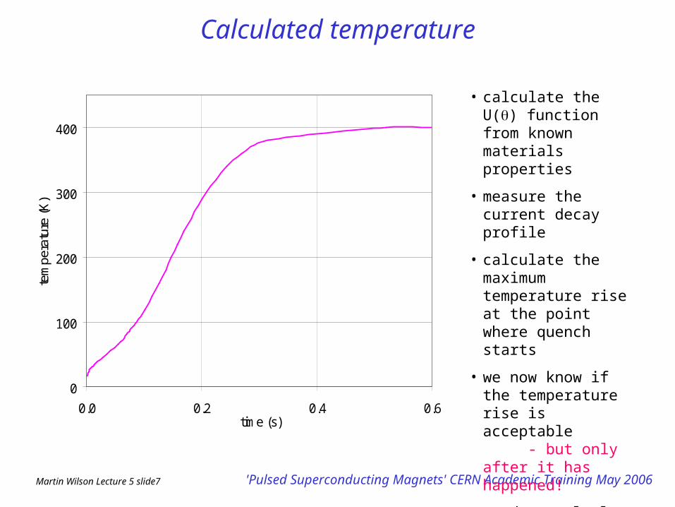
Calculated temperature
0
100
200
300
400
0.0 0.2 0.4 0.6time (s)
tem
pera
ture
(K)
• calculate the U() function from known materials properties
• measure the current decay profile
• calculate the maximum temperature rise at the point where quench starts
• we now know if the temperature rise is acceptable - but only after it has happened!
• need to calculate current decay curve before quenching
Martin Wilson Lecture 5 slide8 'Pulsed Superconducting Magnets' CERN Academic Training May 2006
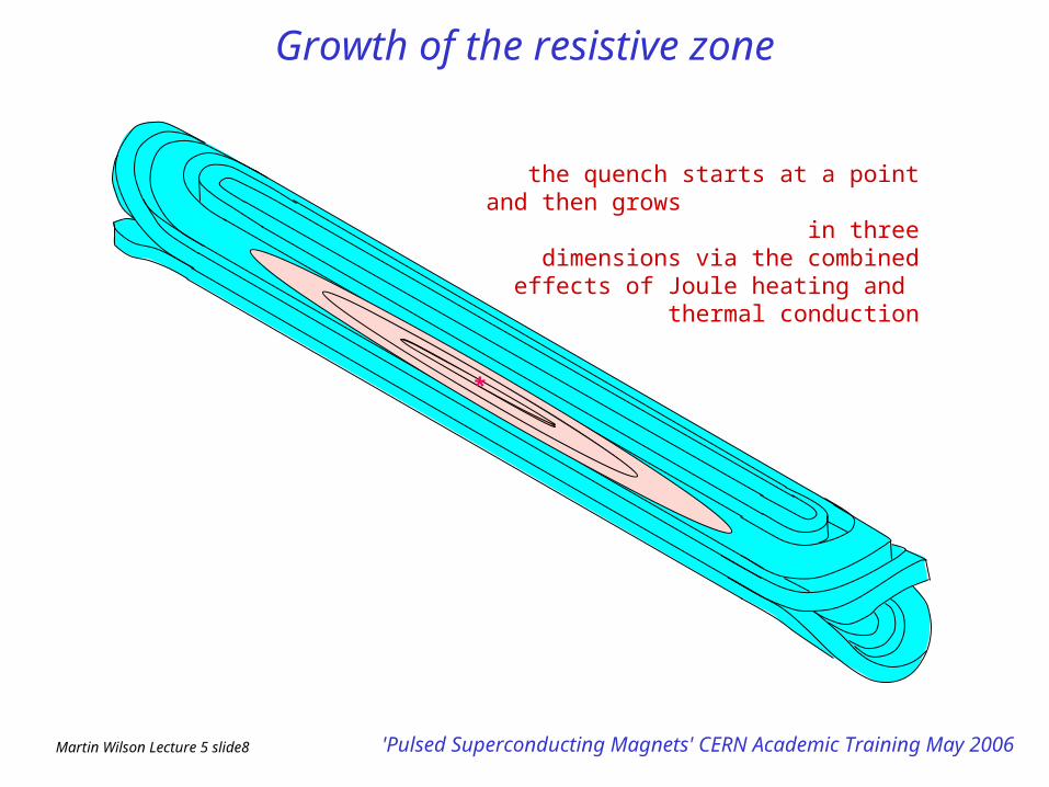
Growth of the resistive zone
*
the quench starts at a point and then grows in three dimensions via the
combined effects of Joule heating and
thermal conduction
Martin Wilson Lecture 5 slide9 'Pulsed Superconducting Magnets' CERN Academic Training May 2006
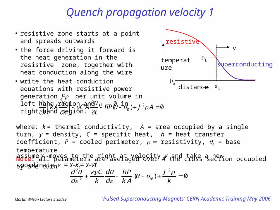
Quench propagation velocity 1
• resistive zone starts at a point and spreads outwards
• the force driving it forward is the heat generation in the resistive zone, together with heat conduction along the wire
• write the heat conduction equations with resistive power generation J2 per unit volume in left hand region and = 0 in right hand region.
where: k = thermal conductivity, A = area occupied by a single turn, = density, C = specific heat, h = heat transfer coefficient, P = cooled perimeter, resistivity, o = base temperature
Note: all parameters are averaged over A the cross section occupied by one turn
0)( 20
AJhPt
ACx
Akx
assume xt moves to the right at velocity v and take a new coordinate= x-xt= x-vt
0)(2
02
2
k
J
Ak
Ph
d
d
k
Cv
d
d
xt
t
v
o
resistive
superconducting temperature
distance
Martin Wilson Lecture 5 slide10 'Pulsed Superconducting Magnets' CERN Academic Training May 2006
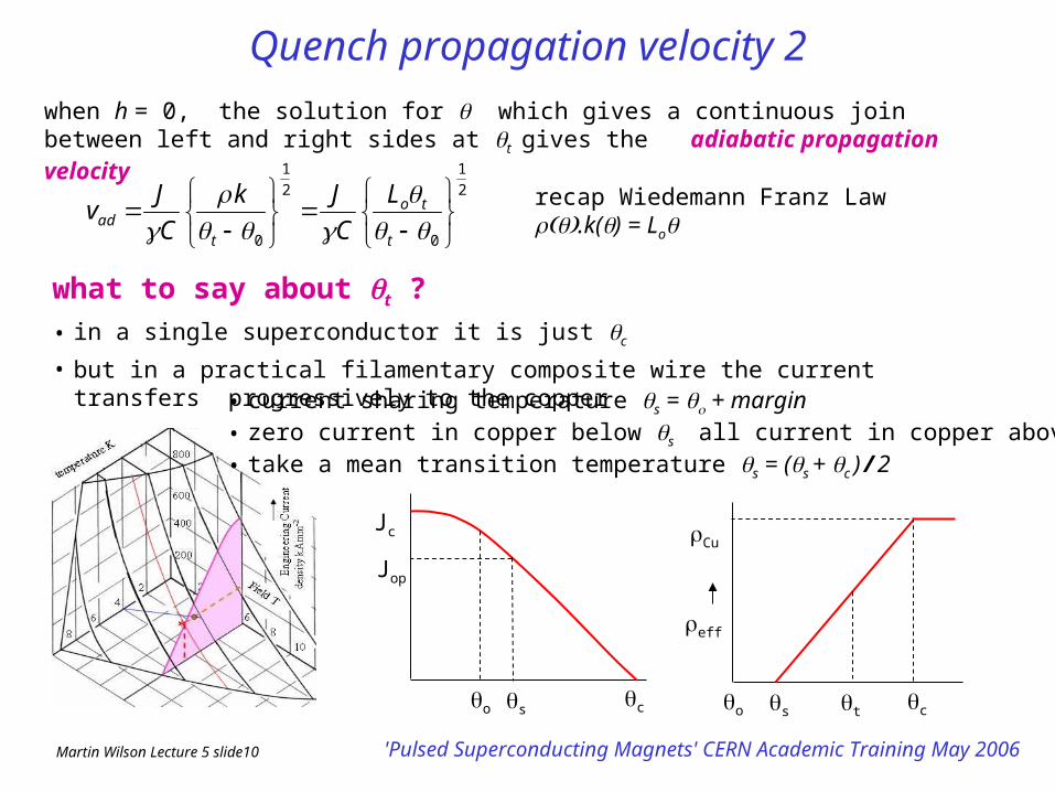
Quench propagation velocity 2when h = 0, the solution for which gives a continuous join between left and right sides at t
gives the adiabatic propagation velocity
2
1
0
2
1
0
t
to
tad
L
C
Jk
C
Jv recap Wiedemann Franz Law .k() = Lo
what to say about t ?
• in a single superconductor it is just c
• but in a practical filamentary composite wire the current transfers progressively to the copper
Jc
o sc
Jop
• current sharing temperature s = + margin• zero current in copper below s all current in copper above s
• take a mean transition temperature s = (s + c ) / 2
o s t c
eff
Cu
Martin Wilson Lecture 5 slide11 'Pulsed Superconducting Magnets' CERN Academic Training May 2006
Quench propagation velocity 32
1
long
trans
long
trans
k
k
v
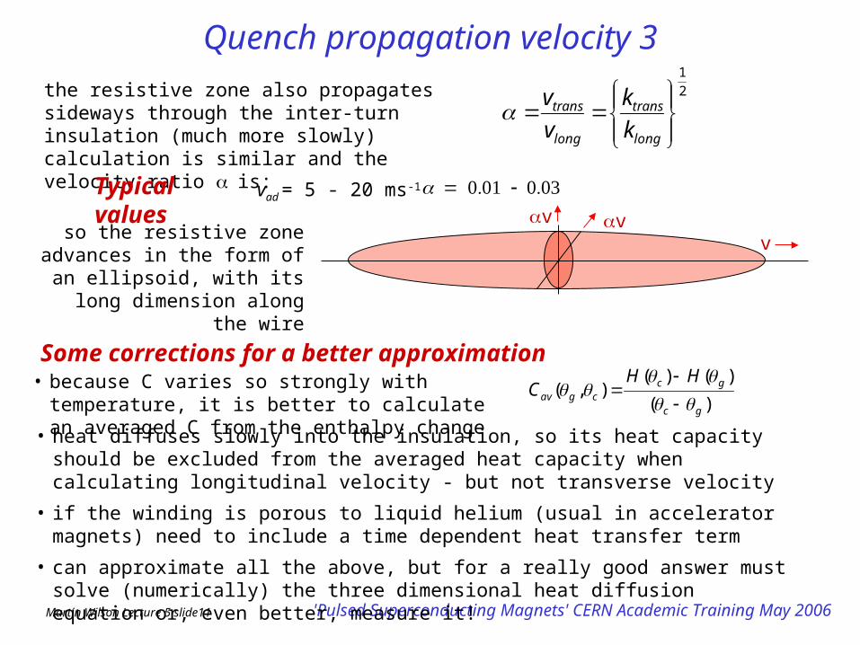
vthe resistive zone also propagates sideways through the inter-turn insulation (much more slowly) calculation is similar and the velocity ratio is:
Typical values
vad = 5 - 20 ms-1
vvv
so the resistive zone advances in the form of an ellipsoid, with its
long dimension along the wire
• heat diffuses slowly into the insulation, so its heat capacity should be excluded from the averaged heat capacity when calculating longitudinal velocity - but not transverse velocity
• if the winding is porous to liquid helium (usual in accelerator magnets) need to include a time dependent heat transfer term
• can approximate all the above, but for a really good answer must solve (numerically) the three dimensional heat diffusion equation or, even better, measure it!
Some corrections for a better approximation
)(
)()(),(
gc
gccgav
HHC
• because C varies so strongly with temperature, it is better to calculate an averaged C from the enthalpy change
Martin Wilson Lecture 5 slide12 'Pulsed Superconducting Magnets' CERN Academic Training May 2006
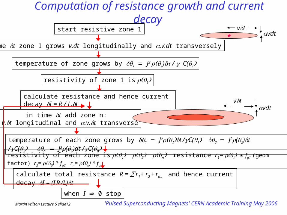
Computation of resistance growth and current decay
start resistive zone 1
in time t zone 1 grows v.dt longitudinally and .v.dt transversely
temperature of zone grows by 1 J2 1) / C(1
resistivity of each zone is 2nresistance r1= fg1 (geom factor) r2= 2) * fg2 rn= n)
* fgn
calculate resistance and hence current decay I = R / L.t
in time t add zone n: v.t longitudinal and .v.t transverse
temperature of each zone grows by 1 Jt /C(1 J2(2)t /C(n J2(1)dt /C(n
resistivity of zone 1 is 1
calculate total resistance R = r1+ r2 + rn.. and hence current decay I = (I R /L)t
when I 0 stop
vtvdt
vtvdt
*
Martin Wilson Lecture 5 slide13 'Pulsed Superconducting Magnets' CERN Academic Training May 2006
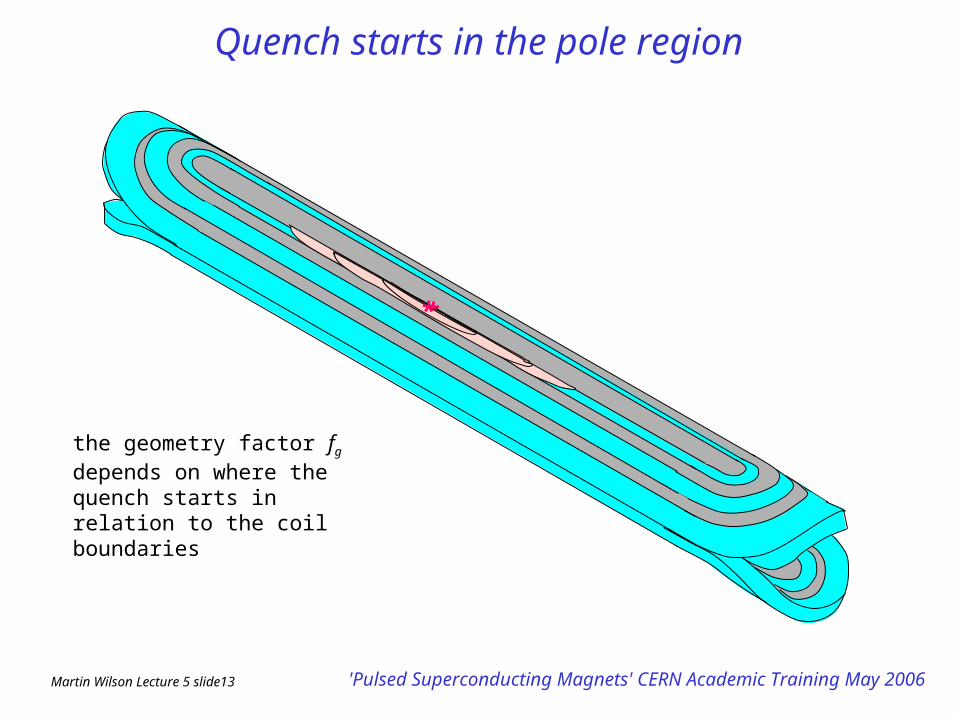
Quench starts in the pole region
***
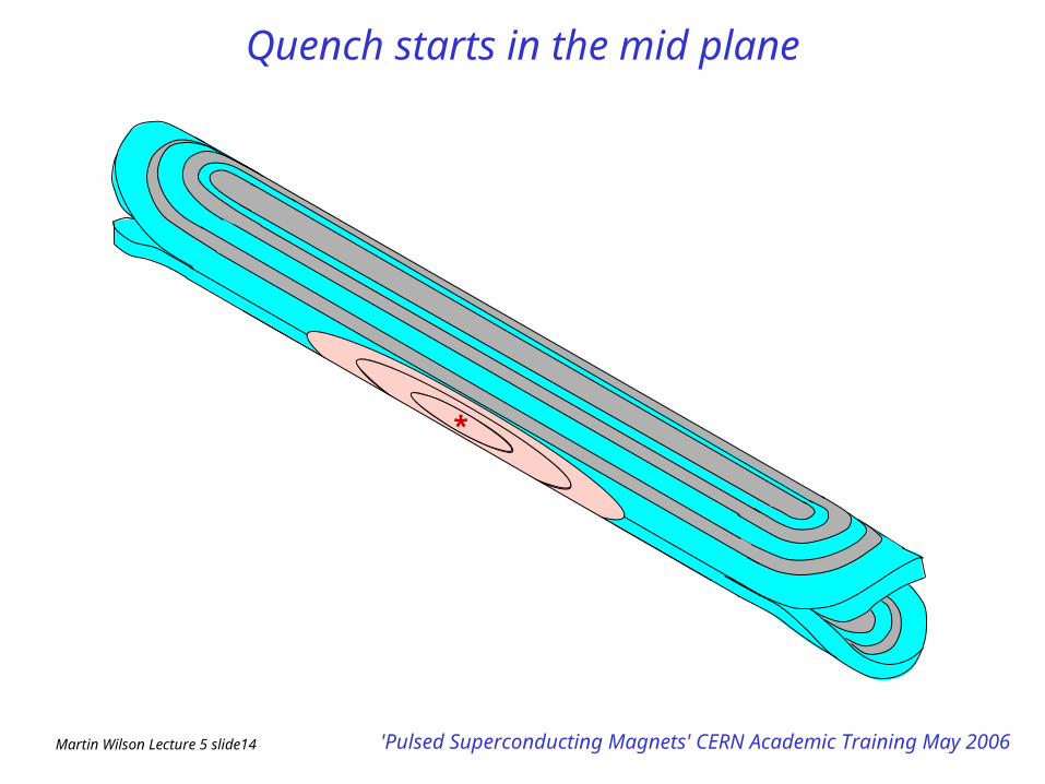
the geometry factor fg depends on where the quench starts in relation to the coil boundaries
Martin Wilson Lecture 5 slide14 'Pulsed Superconducting Magnets' CERN Academic Training May 2006
Quench starts in the mid plane
***
Martin Wilson Lecture 5 slide15 'Pulsed Superconducting Magnets' CERN Academic Training May 2006
0
2000
4000
6000
8000
0.0 0.1 0.2 0.3 0.4 0.5 0.6time (s)
curr
en
t (A
)
measured
pole block
2nd blockmid block
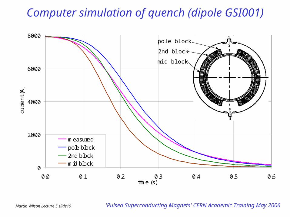
Computer simulation of quench (dipole GSI001)
pole block
2nd block
mid block
Martin Wilson Lecture 5 slide16 'Pulsed Superconducting Magnets' CERN Academic Training May 2006
0
100
200
300
400
500
600
0.0 0.2 0.4 0.6time (s)
tem
pe
ratu
re (
K)
from measured
pole block2nd block
mid block
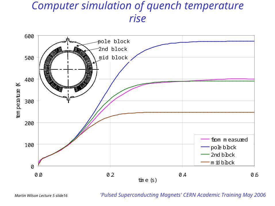
Computer simulation of quench temperature rise
pole block
2nd block
mid block
Martin Wilson Lecture 5 slide17 'Pulsed Superconducting Magnets' CERN Academic Training May 2006
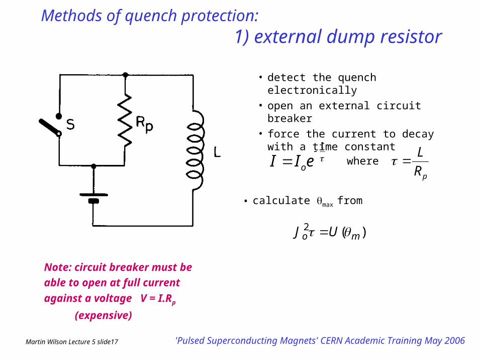
Methods of quench protection:1) external dump
resistor• detect the quench electronically
• open an external circuit breaker
• force the current to decay with a time constant
Note: circuit breaker must be able to
open at full current against a voltage
V = I.Rp (expensive)
• calculate max from
)(2mo UJ
pR
L
t
oeII
where
Martin Wilson Lecture 5 slide18 'Pulsed Superconducting Magnets' CERN Academic Training May 2006
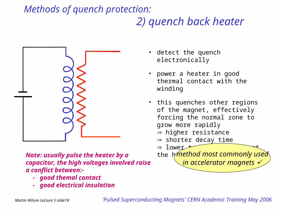
Methods of quench protection:2) quench back heater
• detect the quench electronically
• power a heater in good thermal contact with the winding
• this quenches other regions of the magnet, effectively forcing the normal zone to grow more rapidly
higher resistance shorter decay time lower temperature rise at the hot spot
Note: usually pulse the heater by a capacitor, the high voltages involved raise a conflict between:-
- good themal contact - good electrical insulation
method most commonly used in accelerator magnets
Martin Wilson Lecture 5 slide19 'Pulsed Superconducting Magnets' CERN Academic Training May 2006
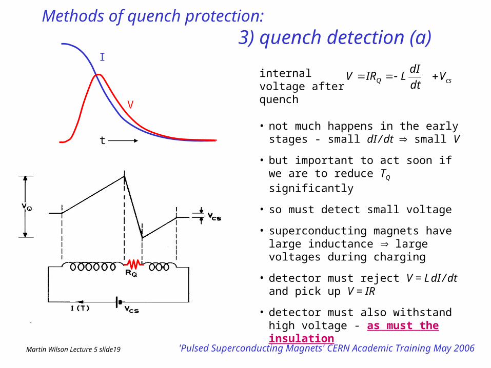
Methods of quench protection:3) quench detection (a)
• not much happens in the early stages - small dI / dt small V
• but important to act soon if we are to reduce TQ significantly
• so must detect small voltage
• superconducting magnets have large inductance large voltages during charging
• detector must reject V = L dI / dt and pick up V = IR
• detector must also withstand high voltage - as must the insulation
internal voltage after quench
I
V
csQ Vdt
dILIRV
t
Martin Wilson Lecture 5 slide20 'Pulsed Superconducting Magnets' CERN Academic Training May 2006
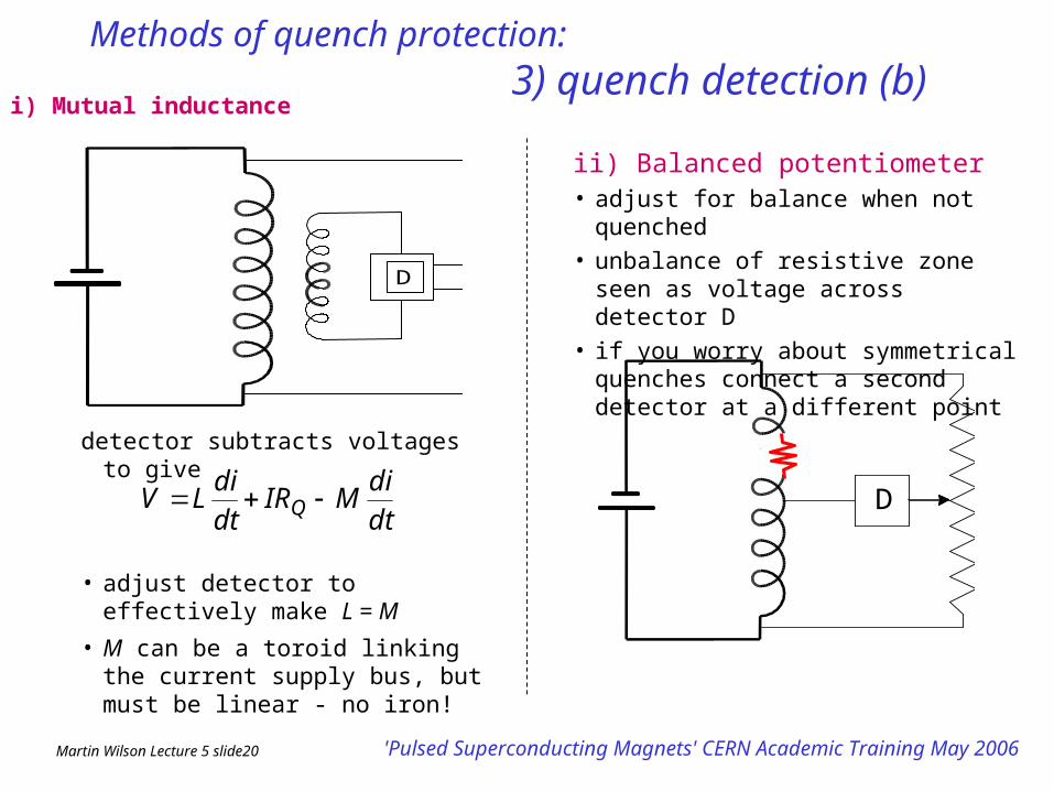
Methods of quench protection:3) quench detection (b)
ii) Balanced potentiometer• adjust for balance when not quenched
• unbalance of resistive zone seen as voltage across detector D
• if you worry about symmetrical quenches connect a second detector at a different point
D
D
detector subtracts voltages to give
• adjust detector to effectively make L = M
• M can be a toroid linking the current supply bus, but must be linear - no iron!
dt
diMIR
dt
diLV Q
i) Mutual inductance
Martin Wilson Lecture 5 slide21 'Pulsed Superconducting Magnets' CERN Academic Training May 2006
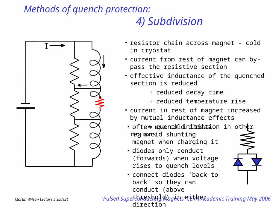
Methods of quench protection:4) Subdivision
• resistor chain across magnet - cold in cryostat
• current from rest of magnet can by-pass the resistive section
• effective inductance of the quenched section is reduced
reduced decay time
reduced temperature rise
• current in rest of magnet increased by mutual inductance effects
quench initiation in other regions
I
• often use cold diodes to avoid shunting magnet when charging it
• diodes only conduct (forwards) when voltage rises to quench levels
• connect diodes 'back to back' so they can conduct (above threshold) in either direction
Martin Wilson Lecture 5 slide22 'Pulsed Superconducting Magnets' CERN Academic Training May 2006
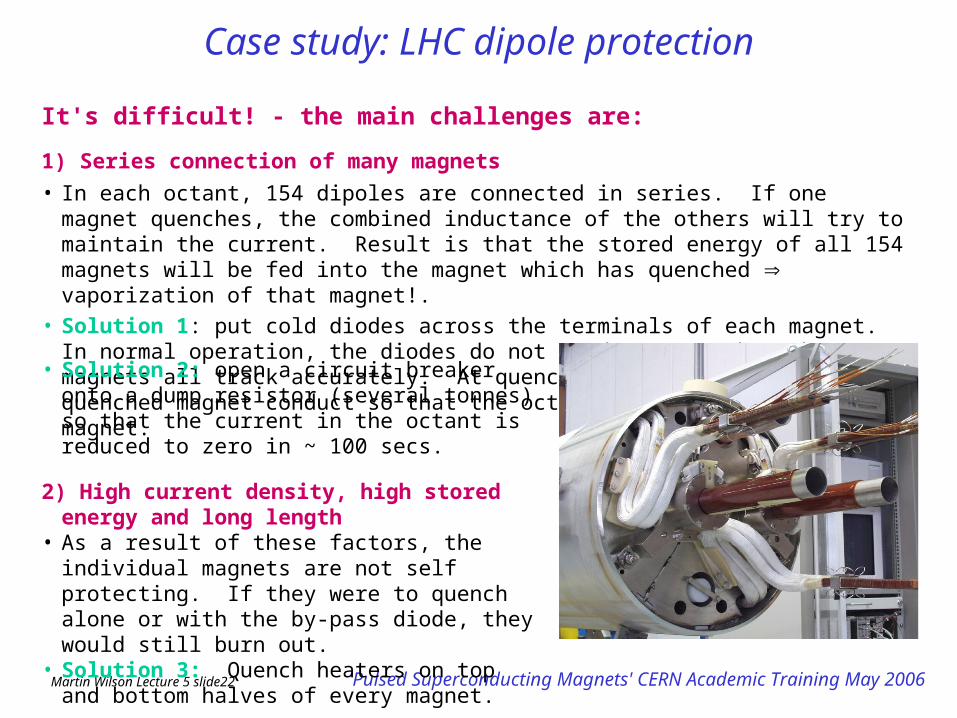
Case study: LHC dipole protection
It's difficult! - the main challenges are:
1) Series connection of many magnets
• In each octant, 154 dipoles are connected in series. If one magnet quenches, the combined inductance of the others will try to maintain the current. Result is that the stored energy of all 154 magnets will be fed into the magnet which has quenched vaporization of that magnet!.
• Solution 1: put cold diodes across the terminals of each magnet. In normal operation, the diodes do not conduct - so that the magnets all track accurately. At quench, the diodes of the quenched magnet conduct so that the octant current by-passes that magnet.
• Solution 2: open a circuit breaker onto a dump resistor (several tonnes) so that the current in the octant is reduced to zero in ~ 100 secs.
2) High current density, high stored energy and long length
• As a result of these factors, the individual magnets are not self protecting. If they were to quench alone or with the by-pass diode, they would still burn out.
• Solution 3: Quench heaters on top and bottom halves of every magnet.
Martin Wilson Lecture 5 slide23 'Pulsed Superconducting Magnets' CERN Academic Training May 2006
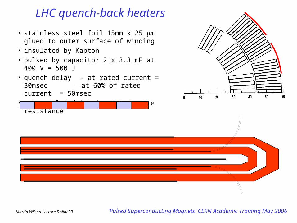
LHC quench-back heaters
• stainless steel foil 15mm x 25 m glued to outer surface of winding
• insulated by Kapton
• pulsed by capacitor 2 x 3.3 mF at 400 V = 500 J
• quench delay - at rated current = 30msec - at 60% of rated current =
50msec
• copper plated 'stripes' to reduce resistance
Martin Wilson Lecture 5 slide24 'Pulsed Superconducting Magnets' CERN Academic Training May 2006
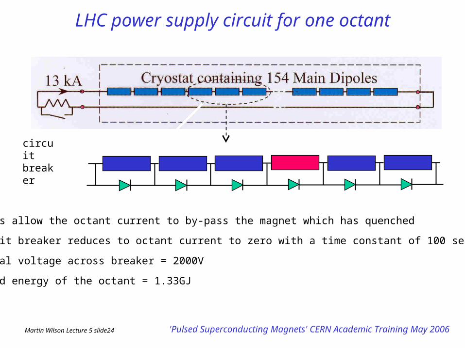
LHC power supply circuit for one octant
circuit breaker
• diodes allow the octant current to by-pass the magnet which has quenched
• circuit breaker reduces to octant current to zero with a time constant of 100 sec
• initial voltage across breaker = 2000V
• stored energy of the octant = 1.33GJ
Martin Wilson Lecture 5 slide25 'Pulsed Superconducting Magnets' CERN Academic Training May 2006
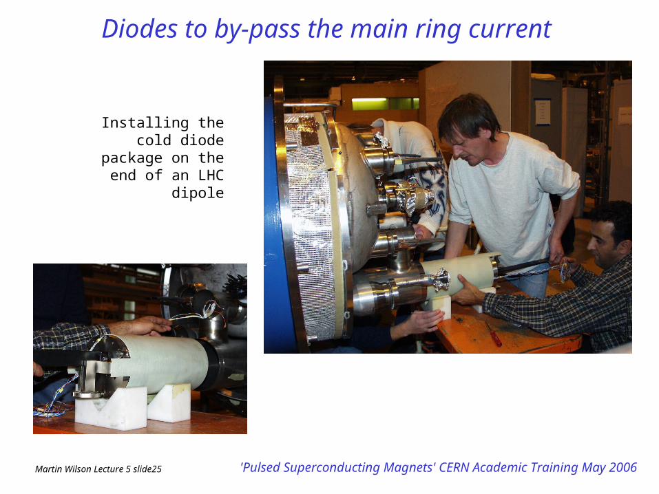
Diodes to by-pass the main ring current
Installing the cold diode package on the end of an
LHC dipole
Martin Wilson Lecture 5 slide26 'Pulsed Superconducting Magnets' CERN Academic Training May 2006
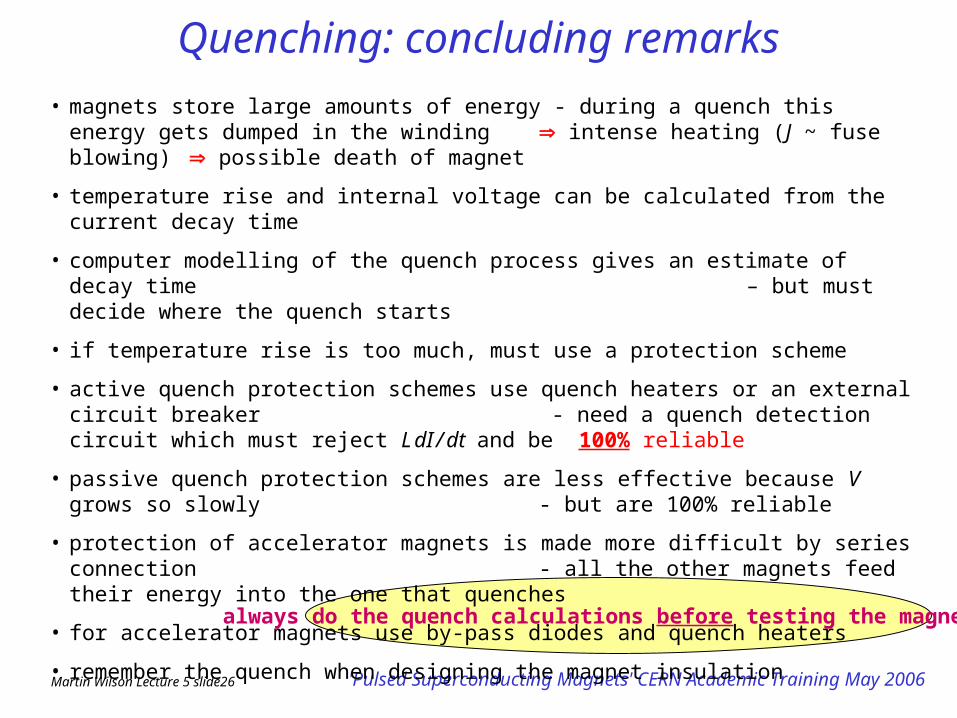
Quenching: concluding remarks• magnets store large amounts of energy - during a quench this energy gets dumped in the winding
intense heating (J ~ fuse blowing) possible death of magnet
• temperature rise and internal voltage can be calculated from the current decay time
• computer modelling of the quench process gives an estimate of decay time – but must decide where the quench starts
• if temperature rise is too much, must use a protection scheme
• active quench protection schemes use quench heaters or an external circuit breaker - need a quench detection circuit which must reject L dI / dt and be 100% reliable
• passive quench protection schemes are less effective because V grows so slowly - but are 100% reliable
• protection of accelerator magnets is made more difficult by series connection - all the other magnets feed their energy into the one that quenches
• for accelerator magnets use by-pass diodes and quench heaters
• remember the quench when designing the magnet insulation
always do the quench calculations before testing the magnet
Martin Wilson Lecture 5 slide27 'Pulsed Superconducting Magnets' CERN Academic Training May 2006
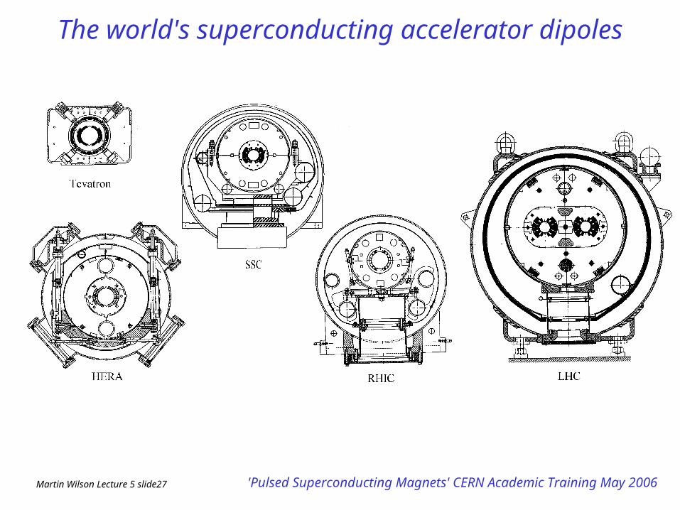
The world's superconducting accelerator dipoles
Martin Wilson Lecture 5 slide28 'Pulsed Superconducting Magnets' CERN Academic Training May 2006
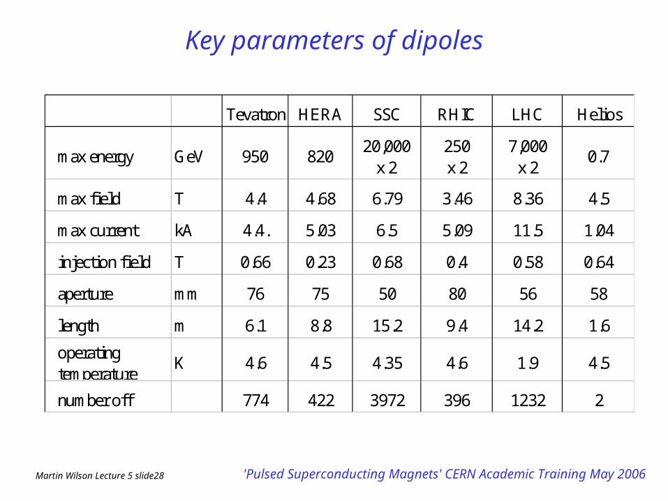
Key parameters of dipoles
Tevatron HERA SSC RHIC LHC Helios
max energy GeV 950 82020,000
x 2250 x 2
7,000 x 2
0.7
max field T 4.4 4.68 6.79 3.46 8.36 4.5
max current kA 4.4. 5.03 6.5 5.09 11.5 1.04
injection field T 0.66 0.23 0.68 0.4 0.58 0.64
aperture mm 76 75 50 80 56 58
length m 6.1 8.8 15.2 9.4 14.2 1.6
operating temperature
K 4.6 4.5 4.35 4.6 1.9 4.5
number off 774 422 3972 396 1232 2

Martin Wilson Lecture 5 slide29 'Pulsed Superconducting Magnets' CERN Academic Training May 2006
Superconducting cables of the world's accelerators
filament dia m
cable w idth mm
twist pitch mm
wire surface
Tevatron 6 7.8 66 zebra
accelerator cable
HERA 14-16 10
RHIC 6 9.7
6 12.3
95 SnAg
73 copper
79 copper
LHC 7 15 115 SnAg pre-ox
SSC
40 copperHelios 8.5 3.2
Martin Wilson Lecture 5 slide30 'Pulsed Superconducting Magnets' CERN Academic Training May 2006
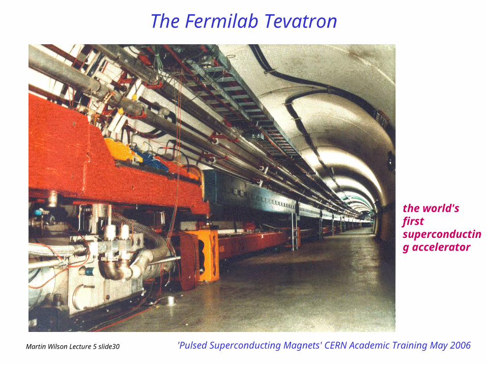
The Fermilab Tevatron
the world's first superconducting accelerator
Martin Wilson Lecture 5 slide31 'Pulsed Superconducting Magnets' CERN Academic Training May 2006
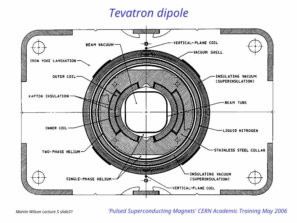
Tevatron dipole
Martin Wilson Lecture 5 slide32 'Pulsed Superconducting Magnets' CERN Academic Training May 2006
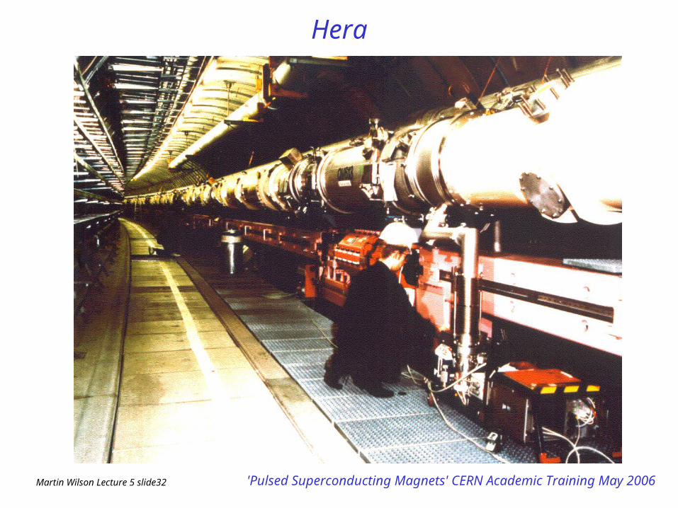
Hera
Martin Wilson Lecture 5 slide33 'Pulsed Superconducting Magnets' CERN Academic Training May 2006
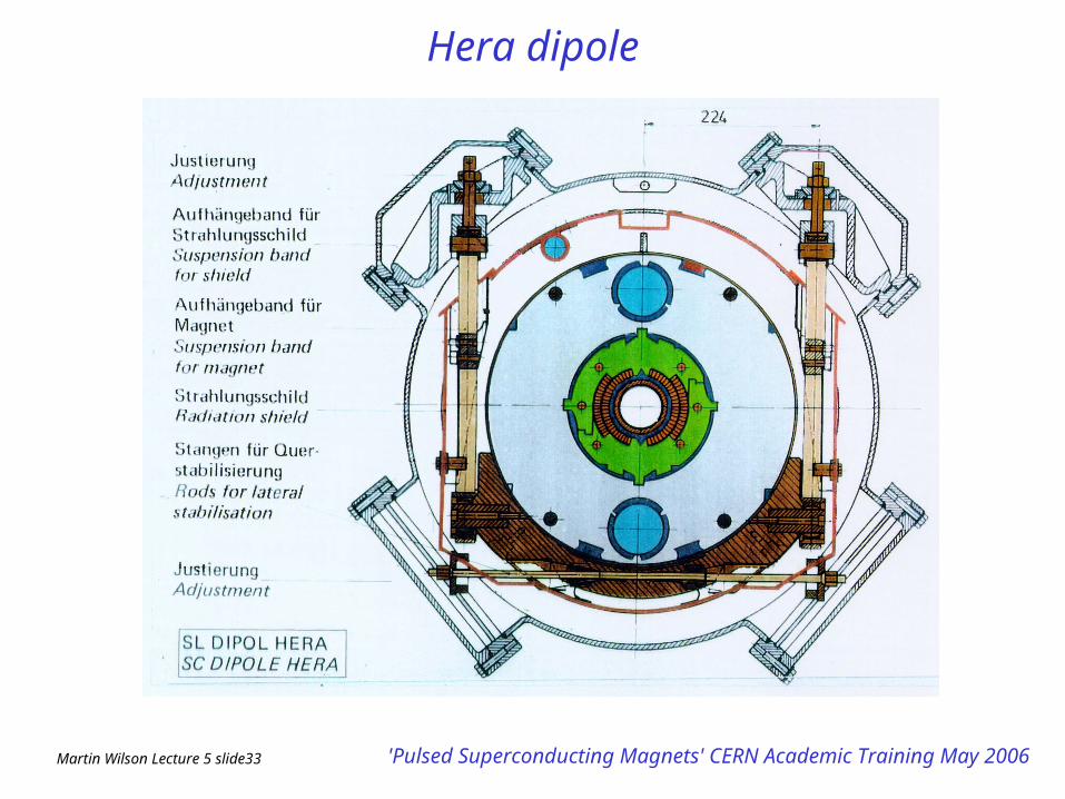
Hera dipole
Martin Wilson Lecture 5 slide34 'Pulsed Superconducting Magnets' CERN Academic Training May 2006
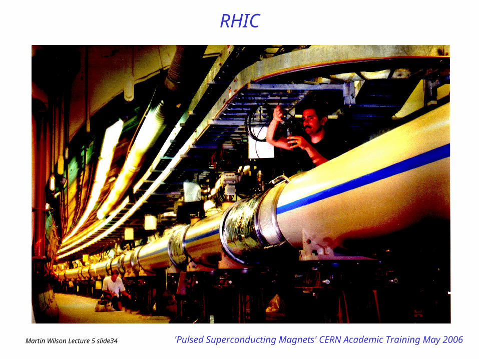
RHIC
Martin Wilson Lecture 5 slide35 'Pulsed Superconducting Magnets' CERN Academic Training May 2006
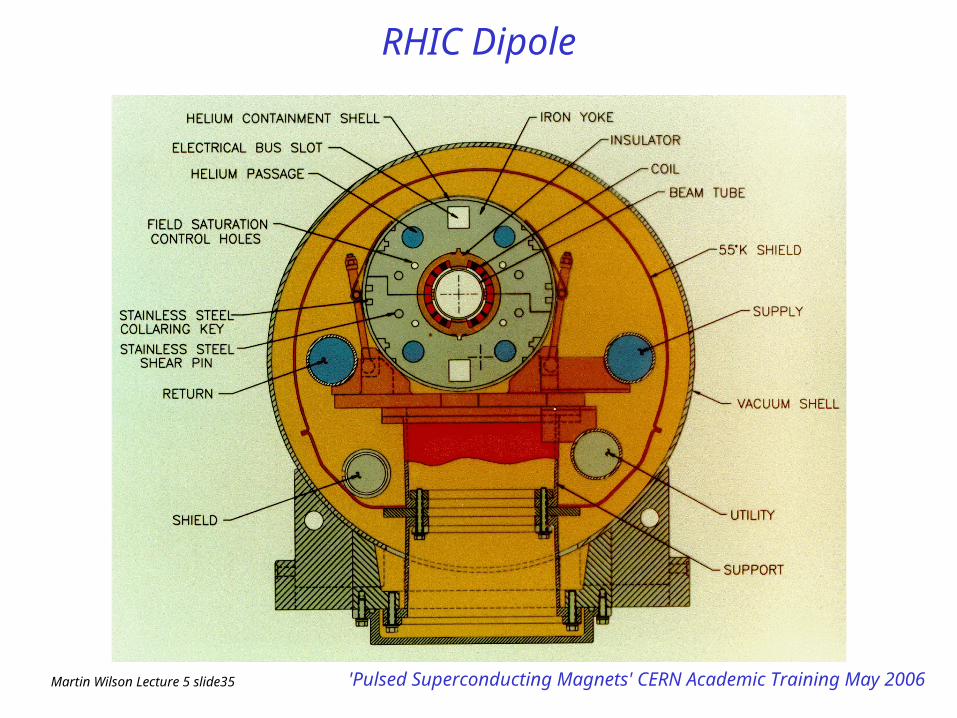
RHIC Dipole
Martin Wilson Lecture 5 slide36 'Pulsed Superconducting Magnets' CERN Academic Training May 2006
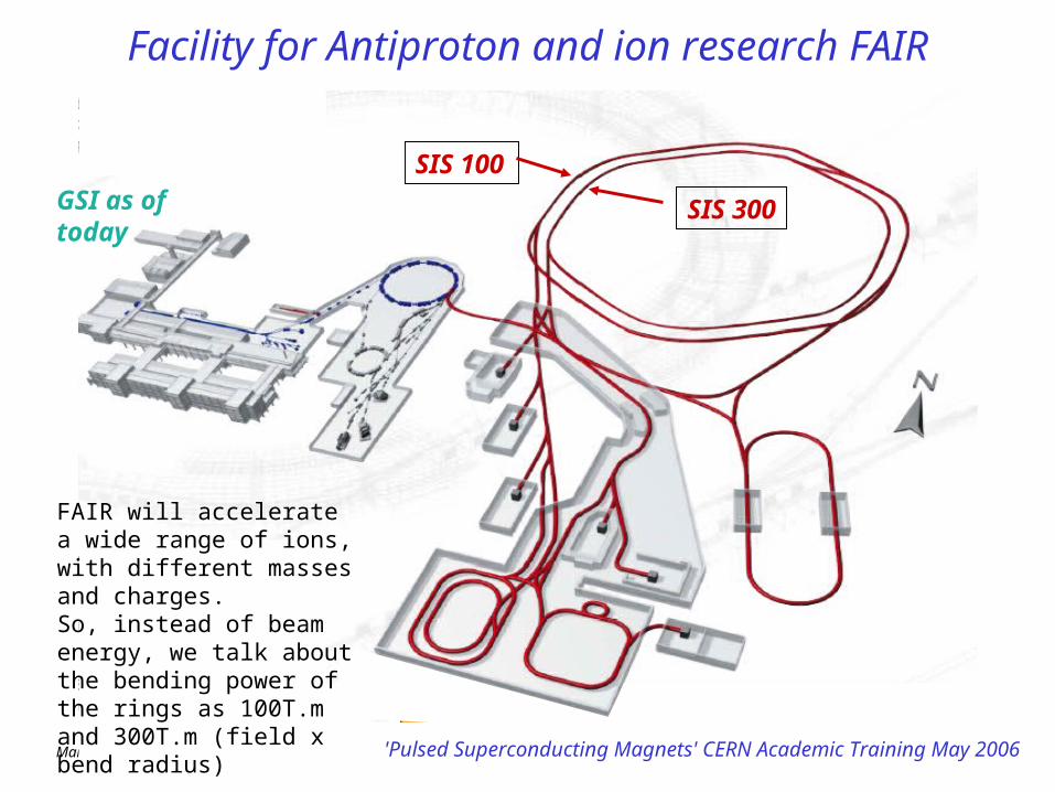
Facility for Antiproton and ion research FAIR
SIS 300
SIS 100GSI as of today
FAIR will accelerate a wide range of ions, with different masses and charges.So, instead of beam energy, we talk about the bending power of the rings as 100T.m and 300T.m (field x bend radius)
Martin Wilson Lecture 5 slide37 'Pulsed Superconducting Magnets' CERN Academic Training May 2006
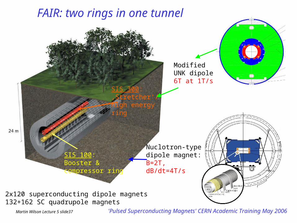
FAIR: two rings in one tunnel
SIS 100: Booster &compressor ring
SIS 300: ‚Stretcher‘/high energy ring
Nuclotron-typedipole magnet: B=2T, dB/dt=4T/s
2x120 superconducting dipole magnets132+162 SC quadrupole magnets
Modified UNK dipole 6T at 1T/s
Martin Wilson Lecture 5 slide38 'Pulsed Superconducting Magnets' CERN Academic Training May 2006
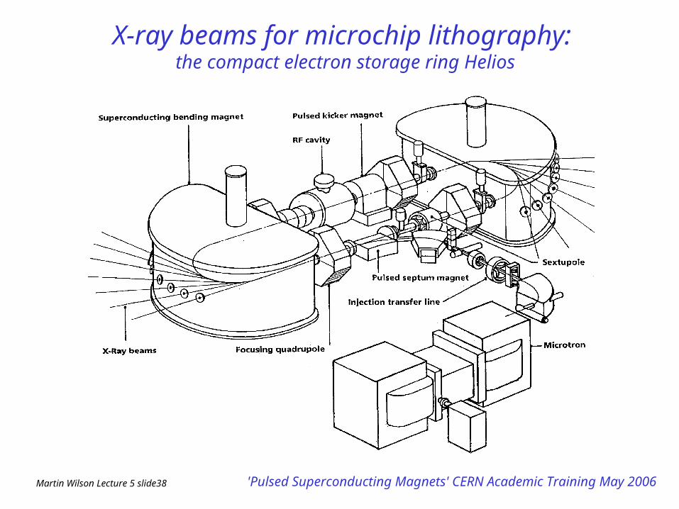
X-ray beams for microchip lithography: the compact electron storage ring Helios
Martin Wilson Lecture 5 slide39 'Pulsed Superconducting Magnets' CERN Academic Training May 2006
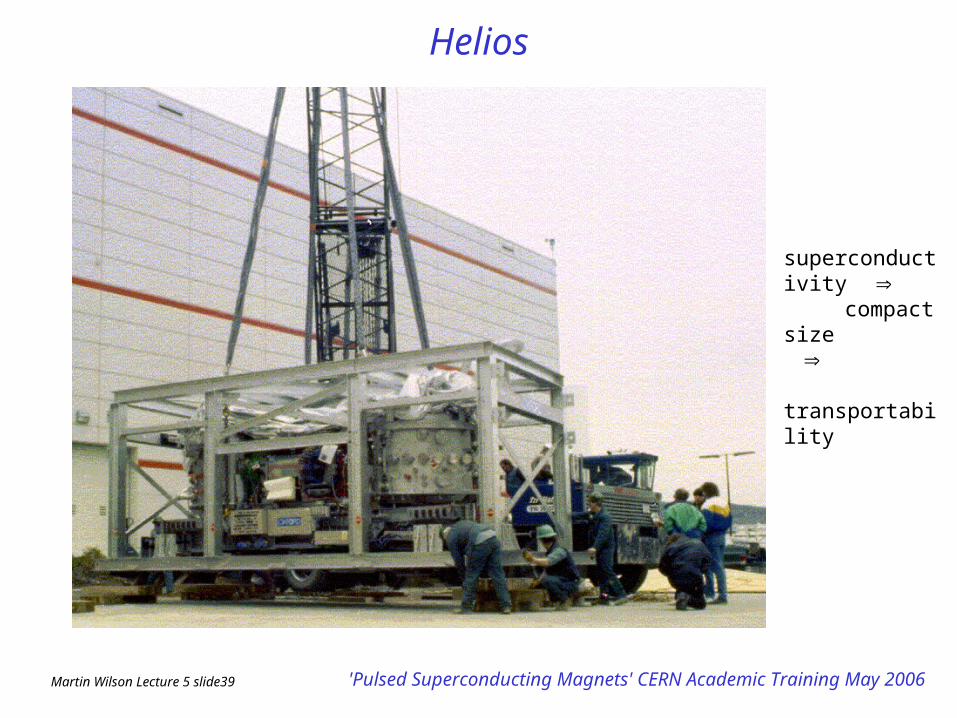
Helios
superconductivity compact size transportability
Martin Wilson Lecture 5 slide40 'Pulsed Superconducting Magnets' CERN Academic Training May 2006
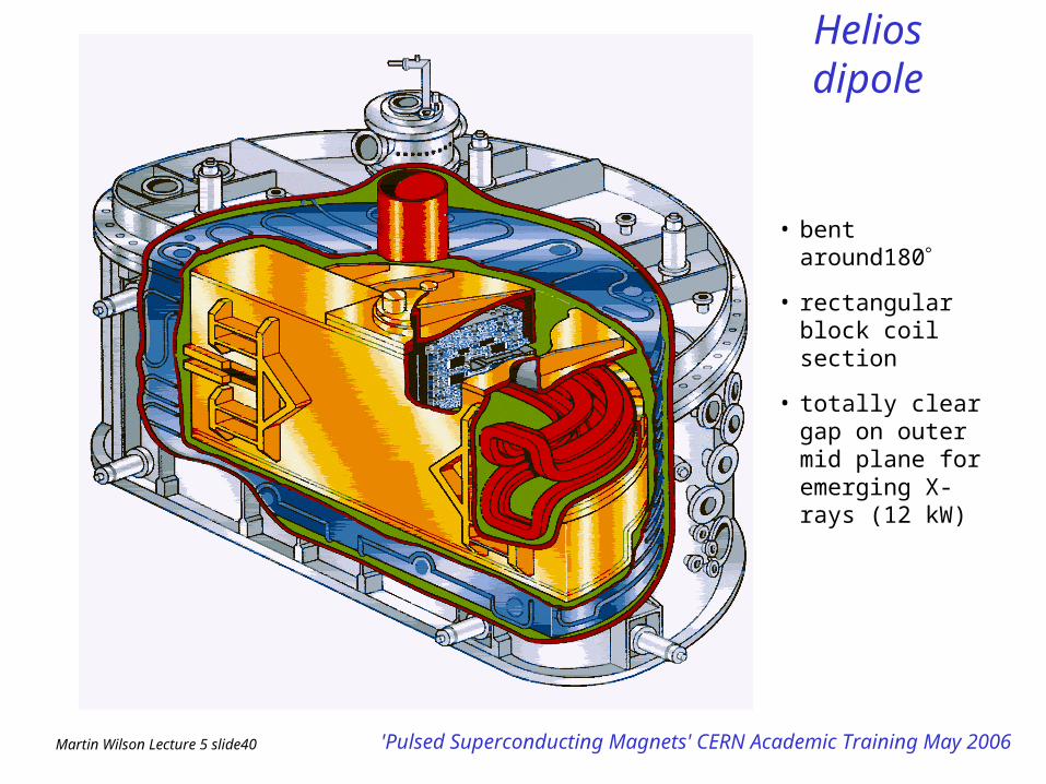
Helios dipole
• bent around180
• rectangular block coil section
• totally clear gap on outer mid plane for emerging X-rays (12 kW)
Martin Wilson Lecture 5 slide41 'Pulsed Superconducting Magnets' CERN Academic Training May 2006
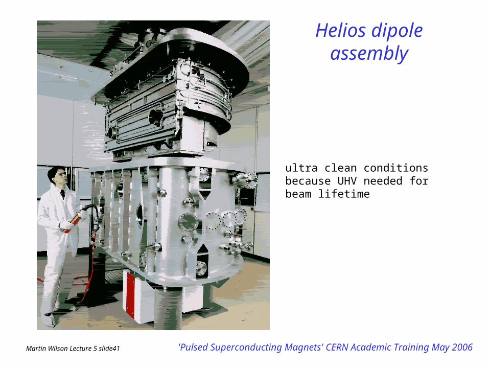
Helios dipole assembly
ultra clean conditions because UHV needed for beam lifetime


![MuCool Superconducting Solenoid Quench …...Index Terms— Superconducting solenoid, Magnetic field, Quench, 3D simulations, Test Stand. I. INTRODUCTION HE MUCOOL experiment [1] magnet](https://static.fdocuments.net/doc/165x107/5e92b2bd1d72c02008514bd1/mucool-superconducting-solenoid-quench-index-termsa-superconducting-solenoid.jpg)