MARS SCIENCE LABORATORY ROBOTIC ARM -...
8
MARS SCIENCE LABORATORY ROBOTIC ARM Principal Author Rius Billing (1) , Co-Author Richard Fleischner (2) , (1) MDA Information Systems, Inc. Space Division, Robotics and Mechanisms, 1250 Lincoln Ave, Pasadena, CA 91103, USA, Email: [email protected] (2) MDA Information Systems, Inc. Space Division, Robotics and Mechanisms, 1250 Lincoln Ave, Pasadena, CA 91103, USA, Email: [email protected] ABSTRACT The Mars Science Laboratory Robotic Arm (MSL RA) is a critical, single–fault-tolerant mechanism in the MSL science mission that must deliver 5 of the rover’s 12 science instruments to the Martian surface. This paper will describe the design, build, and test methodology which evolved as the science payload matured over the course of the 4-year project. Lessons learned based on the EM and Flight unit testing will also be discussed. 1. INTRODUCTION The Mars Science Laboratory mission is NASA’s most ambitious science mission to another planet. MSL incorporates many lessons learned from the Pathfinder mission and Sojourner rover, the twin Mars Exploration Rovers, and the Phoenix Lander. The Robotic Arm will be a key part of the Sample Acquisition, Processing, and Handling (SA/SPaH) system. The RA will be responsible for accurately placing the 5 turret-mounted instruments on their respective targets and acquiring samples. These instruments are a drill capable of capturing rock samples, MAHLI camera, Dust Removal Tool (DRT), Alpha Particle X-Ray Spectrometer (APXS), and CHIMRA. After a sample has been acquired by the drill or the scoop on the CHIMRA, the sample will be transferred to the CHIMRA processing unit and use gravity, assisted by induced vibration, and coordinated movement of the RA to process samples to deliver to the rover-mounted science instruments for soil tests. The MSL rover will carry the most advanced payload of scientific gear ever used on the Martian surface, a payload more than 10 times as massive as those of earlier Mars rovers. Its primary scientific goal will be to investigate whether past conditions had been favorable for microbial life and to accomplish acquisition and handling while preserving clues in the rocks about possible past life. Over the last 10 years, MDA-US (formerly Alliance Spacesystems, Inc) has designed and built every robotic arm successfully deployed and operated on the surface of Mars. The IDD robotic arms from the Mars Exploration Rover have been working on the twin rovers Spirit and Opportunity since 2004 and each played a large role in the discovery of the existence of water on the Martian surface. The Phoenix robotic arm was successfully deployed to the Martian surface in 2008 and was instrumental in the discovery of frozen surface and subsurface water. The MSL robotic arm program leverages the experience garnered from the MER and Phoenix programs to produce an instrument capable of surviving a lifetime 7 times longer than any previous in-situ planetary mission. The main attributes of the MSL Robotic Arm are: • 5 degrees of freedom • 2.2 meters outstretched length from base to center of instrument turret • 67 kg mass without turret instruments • 5 turret instruments with mass of 34 kg • Electrical cabling system with 920 signals traversing the length of the arm • Two dual-use caging mechanisms capable of surviving landing loads of over 20g, passively re-stowing the RA after deployment, and surviving rover driving loads of 8g • Capable of surviving temperature range of - 128ºC to +50ºC and operating within a temperature range of -110ºC and +50ºC _________________________________________________ ‘14th European Space Mechanisms & Tribology Symposium – ESMATS 2011’ Constance, Germany, 28–30 September 2011 363
Transcript of MARS SCIENCE LABORATORY ROBOTIC ARM -...

MARS SCIENCE LABORATORY ROBOTIC ARM
Principal Author Rius Billing(1)
, Co-Author Richard Fleischner(2)
,
(1)MDA Information Systems, Inc. Space Division, Robotics and Mechanisms,
1250 Lincoln Ave, Pasadena, CA 91103, USA, Email: [email protected] (2)MDA Information Systems, Inc. Space Division, Robotics and Mechanisms,
1250 Lincoln Ave, Pasadena, CA 91103, USA, Email: [email protected]
ABSTRACT
The Mars Science Laboratory Robotic Arm (MSL RA)
is a critical, single–fault-tolerant mechanism in the
MSL science mission that must deliver 5 of the rover’s
12 science instruments to the Martian surface.
This paper will describe the design, build, and test
methodology which evolved as the science payload
matured over the course of the 4-year project. Lessons
learned based on the EM and Flight unit testing will
also be discussed.
1. INTRODUCTION
The Mars Science Laboratory mission is NASA’s most
ambitious science mission to another planet. MSL
incorporates many lessons learned from the Pathfinder
mission and Sojourner rover, the twin Mars
Exploration Rovers, and the Phoenix Lander.
The Robotic Arm will be a key part of the Sample
Acquisition, Processing, and Handling (SA/SPaH)
system. The RA will be responsible for accurately
placing the 5 turret-mounted instruments on their
respective targets and acquiring samples. These
instruments are a drill capable of capturing rock
samples, MAHLI camera, Dust Removal Tool (DRT),
Alpha Particle X-Ray Spectrometer (APXS), and
CHIMRA. After a sample has been acquired by the
drill or the scoop on the CHIMRA, the sample will be
transferred to the CHIMRA processing unit and use
gravity, assisted by induced vibration, and coordinated
movement of the RA to process samples to deliver to
the rover-mounted science instruments for soil tests.
The MSL rover will carry the most advanced payload
of scientific gear ever used on the Martian surface, a
payload more than 10 times as massive as those of
earlier Mars rovers. Its primary scientific goal will be
to investigate whether past conditions had been
favorable for microbial life and to accomplish
acquisition and handling while preserving clues in the
rocks about possible past life.
Over the last 10 years, MDA-US (formerly Alliance
Spacesystems, Inc) has designed and built every
robotic arm successfully deployed and operated on the
surface of Mars. The IDD robotic arms from the Mars
Exploration Rover have been working on the twin
rovers Spirit and Opportunity since 2004 and each
played a large role in the discovery of the existence of
water on the Martian surface. The Phoenix robotic arm
was successfully deployed to the Martian surface in
2008 and was instrumental in the discovery of frozen
surface and subsurface water.
The MSL robotic arm program leverages the
experience garnered from the MER and Phoenix
programs to produce an instrument capable of
surviving a lifetime 7 times longer than any previous
in-situ planetary mission.
The main attributes of the MSL Robotic Arm are:
• 5 degrees of freedom
• 2.2 meters outstretched length from base to
center of instrument turret
• 67 kg mass without turret instruments
• 5 turret instruments with mass of 34 kg
• Electrical cabling system with 920 signals
traversing the length of the arm
• Two dual-use caging mechanisms capable of
surviving landing loads of over 20g, passively
re-stowing the RA after deployment, and
surviving rover driving loads of 8g
• Capable of surviving temperature range of -
128ºC to +50ºC and operating within a
temperature range of -110ºC and +50ºC
_________________________________________________ ‘14th European Space Mechanisms & Tribology Symposium – ESMATS 2011’ Constance, Germany, 28–30 September 2011
363

Because of the complex nature of the mission and the
extended development schedule, there were several
major changes to the MSL architecture passed down
from NASA/JPL that affected the design at a late stage:
• A change throughout all rotary actuators from
dry to wet lubrication because of severe life-
limiting issues found in early actuator testing
• A payload mass increase on the RA
instrument turret from 15 kg to 34 kg, that
required a redesign of restraint and caging
mechanisms for launch and traverse
• An increase in electrical system complexity
that required the cabling system to carry more
than 300 new signals to the reconfigured
instrument cluster
The mission’s duration is 687 Earth days, over 7 times
longer than any planetary rover mission in the past.
Life tests were therefore required and completed to
assure satisfactory performance over this life time.
Testing included life cycle tests for the caging
mechanisms making up the launch lock and restow
system. Bearing life tests were also conducted to prove
the validity of the dry lubrication used on the moving
parts of the cable management system. A full suite of
environmental tests were conducted as well, including
vibration testing and thermal vacuum testing.
2. CONFIGURATION CYCLE
The typical configuration cycle for a planetary robotic
arm is initially comprised of a plethora of tasks that
help refine the configuration and specifications up to
the Preliminary Design Review (PDR). There were 10
mechanical configurations under consideration, some
serial and some in parallel that were reviewed and
analyzed for the following criteria:
• Range of Motion (ROM)
• Workspace access (slimness and dexterity)
• Cable layout down the length of the robotic arm • Loads generated at launch and during rover
traverse
Each distinct configuration generally has advantages
and disadvantages made apparent through detailed
examination, but over the course of development an
optimized configuration arises which fairly equally
distributes performance associated with each of the
four criteria. During this development process, each
configuration is adjusted until ranges of motion and
workspace access are maximized and that the cabling
path is electrically and topologically suitable.
Throughout this optimization process system loads
cases are run on a fairly detailed model of the
configuration which incorporates structural, actuator,
and launch mechanism compliances.
The system loads cases are compiled and arranged in
load groups corresponding to the various subsystems
comprising the robotic arm. As far as design inputs are
concerned, these load groups are considered the current
best understanding of what the launch, landing, and
operation loads will be throughout the arm’s
subcomponents. For the MSL RA, 12 loading
scenarios were used as inputs to the system loads
model. The initial launch loads were derived from the
general specifications of launch vehicle Mass
Acceleration Curves (MAC); random vibration
analysis; conservative landing loads; the operational
loading from Earth operations in 1g; rover-induced
loads from driving; and loads required to preload the
various turret-mounted instruments against the Martian
surface. Loads due to inadvertent actuation of the
robotic arm while still locked in its caging mechanisms
were also considered. Due to early uncertainty in the
design of the rover and joint actuators, many different
combinations of variables were used to span the
anticipated ranges of stiffness. Many load cases were
run incorporating all possible permutations of
stiff/compliant rover structure, stiff/compliant
actuators, etc. The highest case-independent loading
local to each arm subsystem was then segregated and
compiled into an overall worst-cast case scenario for
the arm. This loads scenario was then used as the
364

design driver for the arm structure and caging
mechanisms. As the design matured these 12 different
cases were re-run and the results were used to further
refine the design.
Figure 2, Primary workspace
In addition to structural considerations, the robotic arm
must meet its positioning requirements for targets
inside an assigned volume called the “robotic arm
primary workspace”.
The workspace, as shown in Fig. 2, was defined in the
requirements as “an upright cylinder 80 cm diameter,
100 cm high, positioned 105 cm in front of the front
body of the rover, and extending to 20 cm below the
surface when the rover is on a smooth flat terrain.” An
analysis was performed to ensure that a high
percentage of the workspace could be reached and
preload could be applied to the instruments at almost
any angle the robotic arm is capable of positioning
them. This analysis typically has over a million points
of contact resulting from calculations which take into
account all possible joint angles.
Typically, after the PDR the configuration
development cycle stops and the detail design phase
begins, but because the MSL mission was still
maturing MDA-US was presented with a few new
opportunities. The baselined soil processing
mechanism previously mounted elsewhere on the rover
was now relocated on the arm’s instrument turret. This
change had multiple effects on the RA, most notably
that the turret-mounted instruments mass increased
126% from 15 kg to 34 kg, a 25% overall increase for
the RA system. Additionally, this relocation of
electromechanical components increased the cabling
wire count from 620 to 920. This change required
another round of system loads and workspace analysis
to be carried out because of the mass addition at the
end of the RA. This in turn drove design iterations on
the caging mechanisms and other structural parts.
There was fortunately an earlier accommodation for a
spare flex cable still available in the system.
The development cycle continued past the Critical
Design Review (CDR) as well. This was due to the
fact that the JPL-supplied actuators were not surviving
life tests. The original plan for the entire MSL project
was to develop mechanisms that did not require
external heating due to the limited battery power on the
rover. The actuators were therefore developed with dry
lubrication in mind. Following the life-test failures, the
actuators underwent a design change to incorporate wet
lubrication as well as a material change from Titanium
to Vascomax C250 steel. This change increased
actuator mass from 5.7 kg to 7.8 kg each for the 3 large
actuators, (elevation, azimuth, and elbow) and an
increase from 3.0 kg to 4.2 kg for the 2 smaller
actuators, (wrist and turret). This accounted for an
additional 14% mass increase to the RA system.
Another full iteration of the system loads cases was
run and all piece part analysis was rechecked and
verified with the new system loads.
3. SUBSYSTEM DESIGN
There are 4 basic subsystems to a robotic arm as
designed by MDA-US. These are caging mechanisms,
cabling system, structure, and actuators.
3.1. Caging Mechanisms
Figure 3, Caging mechanisms
Developing the caging mechanisms for a 5 Degree of
Freedom (5 DOF) robotic arm mounted to a moving
platform is an interesting design problem. The
mechanisms have to survive launch and landing loads
throughout the thermal environment and then release
the RA to deploy for use. The mechanisms must also
be able to passively stow and protect the RA during
roving maneuvers. The caging system must also not
over constrain and bind the arm during thermal
transitions which vary, in the case of the MSL arm,
from -128ºC to +50ºC (survival temperature range).
This is very important because the rover front panel
onto which the RA is mounted is Aluminum 7075 and
the RA is primarily Titanium 6AL-4V, two materials
which have vastly different CTEs. Fig. 3 shows the
365

multi-DOF system designed to lock the MSL robotic
arm for launch. The instrument turret is the single
most massive subsystem of the arm and therefore must
be fully constrained in 6 DOF at launch. The elbow of
the RA is constrained only in the directions that are
needed to protect the actuators and structure, with
allowance for the arm to expand and contract relative
to the rover front panel. A dynamic analysis is used to
iterate which degrees of freedom must be locked out to
protect the actuators and structure.
3.2. Cabling System
The cabling system developed for MDA-US robotic
arms is unique in that it spans from the rover bulkhead
to the instrument turret in one piece. The 10m long
flex cables used are very mass and volume efficient
and are an appropriate design solution when 920
signals must pass down a 5-DOF robotic arm. 22
connectors and 555 signals traverse the RA to the five
discrete instruments on the turret. See Fig. 4 for the
comparison of the round wire entering the RA to the
flex cable on the RA. The shortest flex cable
terminates at the azimuth and elevation actuators and is
2.8 m long. Fig. 5 shows the single cable path from
Rover bulkhead to Turret connectors.
Figure 4, round wire bundle vs. flex cable bundle
Another advantage to the flex cable system is that each
individual signal can be customized for its voltage and
current requirements. The flex cable for the turret-
mounted MAHLI camera is a 75 ohm matched
impedance cable tailored for the video signals. Each
flex cable, 8 in total on the MSL RA, contains 2 trace
layers and two shield layers, one on both top and
bottom. Noisy signals such as motor power can be
isolated by arranging them away from quiet signals
such as encoders or resolvers.
Because this robotic arm will be on a lengthy mission
handling rocks and soils, it was required that the flex
spools at each actuator be sealed from the Martian dust.
The specific issue was that dirt could get between the
layers of flex cable and over time abrade the outermost
protective layer of the cable. This protection was
accomplished with phenolic seals at each rotating
interface entering and exiting the flex spools.
Two flex spools on the robotic arm required steel 4-
point bearing be used to let the spool rotate with the
joint. A moly disulphide (MoS2) dry lubricant was
used in the bearing to allow it to function at the
extreme cold temperatures of -128ºC without requiring
a heater. A life test was performed and test results are
shown in section 4.2.
Figure 5, flex cable system
3.3. Structure
The structural members of the robotic arm are
predominantly Titanium 6AL-4V for mass savings and
CTE matching to the bearing steels and housings used
in the actuators. The arm is mounted to the aluminum
rover front panel to the aluminum shoulder bracket.
There is an engineered transition interface between the
aluminum shoulder bracket and the titanium output
bracket which couples to the output shaft of the
azimuth actuator as shown in Fig. 6.
Figure 6, Shoulder bracket and AZ output bracket
The titanium output bracket is designed with integrally-
machined flexures which flex with CTE mismatch-
induced displacements. Since this part is at the
structural root of the RA it was critical that it be
designed to be strong enough in all directions to carry
the system loads, but comply in the direction of CTE-
driven displacements. A bi-pod made of Al 7075
supports the bottom of the titanium coupling piece.
366

3.4. Actuators
The robotic arm joint actuators were furnished by JPL
from a single vendor as were all the actuators on the
mission. This was stipulated as a result of the original
mission requirement not to use external heaters and use
of dry lubrication due to the vendor’s experience with
dry lubricants. MDA-US typically designs robotic arm
actuators in conjunction with the development of the
entire arm. Since the MSL RA actuators were
designed somewhat independently and supplied to
MDA-US, actuator design parameters that would
normally be open to adjustment such as output gearing
and bearing size were for the most part unchangeable.
The robotic arm structure and mechanisms therefore
had to serve the dual purpose of accommodating all the
design loads while protecting the actuators as
delivered. Unlike other robotic arms that MDA-US
designed, an additional DOF constraint was added to
one of the caging mechanisms because loads were
over-stressing the output bearings of the turret actuator.
Interestingly, the additional DOF was added to the
elbow caging mechanism rather than to the turret
caging mechanism, a good demonstration of loads
dependency throughout the arm. Another deviation
from typical MDA-US practice was that the joint
actuator hardstops had to be designed into interface
pieces which were then attached to the actuators. This
was because actuator range of motion design was
MDA-US’s responsibility. Obviously this was less
efficient and accurate than designing hardstop features
directly into the output shaft and housing, not to
mention the need for coordination between MDA-US
and the actuator manufacturer. Another complication
was that because hardstop structures, specifically as
part of a robotic arm, take tremendous loads, the parts
had to be designed early enough to be match drilled
and later pinned to the actuator output shafts before the
actuators were assembled. This meant that
configurational changes had to be set very early. If
changes were needed too long after the match-pinning
process, there was a very real risk of having to match-
machine on a fully assembled actuator. Despite the
precautions taken, because of the aforementioned
change in actuator material, much of the match drilling
had to be redone following program approval of a fully
built and tested actuator made of the new material.
4. TESTING
Elements of the test program fell into two categories:
validation and system testing. Validation testing
consisted of subsystem tests. Two life tests were
conducted, caging mechanisms and flex spool bearing
dry lubrication. Static tests were performed on the
main structural members. System testing consisted of
the full robotic arm assembly for range of motion,
vibration, and thermal vacuum tests.
4.1. Life test: Caging mechanism
The turret re-stow life test was composed of two sub-
tests which together simulated the two distinct mating
geometries and respective tribologies involved in re-
stowing the turret. The first sub-test was life-cycling a
+X capture “parapet” interface, forward-mounted on
the turret re-stow system. The parapets are small
structural towers (or pylons) with special features into
which corresponding turret features engage. The
second was life cycling the –X “hook/duckbill/roller”
capture system. The way this caging interface
functions is that a hook-shaped piece is guided into the
widening “mouth” of the duckbill piece, assisted by a
rolling element to limit drag and/or binding friction.
Two rear-mounted parapets, similar to the forward
mounted parapet, support the duckbill guides and
rollers. The geometry simulation hardware for each
turret interface test incorporated flexures designed to
simulate the stiffness of the turret as mounted at the
end of the forearm with the elbow caging mechanism
engaged. Both subtests were conducted at ambient
temperature and pressure. Each test was 975 cycles (3
times the expected cycles of 325). One cycle is defined
as a turret rotation from 50 degrees (start of re-stow
and non-contacting) to 0 degrees (full re-stow) and
back to 50 degrees. Cycles were conducted at a speed
of approximately 1 RPM, which is more than or equal
to typical Mars operational stowing speeds.
Figure 7, caging mechanism life testing
Under perfect alignment the re-stow capture features
will not come into contact with each other and there
will be no induced load or wear. This ideal case is
obviously not conservative, so both of the
aforementioned sub-tests were set up to generate a
worst-case misalignment load between the mating
pieces. Load values were calculated from worst-case
scenarios with the rover at a 30-degree tilt along with
the RA joint angles set at allowable imprecision
extremes. This resulted in the re-stow capture pieces
displaced from each other with a misalignment of +/-
8mm.
367
At +/-8mm, the +X capture feature simulator generated
a load that increased during capture up to 342 N at the
final stowed location.
Loading on the hook/-duckbill capture interface
similarly increased during capture up to a normal load
of 418 N. The hook/roller capture interface was
subjected to a radial load of 271 N. See Fig. 8 for wear
patterns developed.
Figure 8, wear pattern on parapet duckbill
Both tests were successful despite all the coatings of
Tiodize and MoS2 wearing away before the end of the
first lifetime. These coating were applied to titanium
6Al-4V and Nitronic 60 materials, respectively.
Nevertheless, the contacting geometry and interfacing
features were designed with heavy wear in mind and
margins were still maintained by the end of the test.
4.2. Life test: Flex spool bearing dry lubrication
The ball bearing used in the turret and azimuth flex
spools is a thin section Kaydon X-type bearing with a
thin dense chrome coating and a sputtered MoS2
lubricant. This bearing allows each flex spool to rotate
with the joint (the other 3 flex spools were
kinematically inverted and thus fixed). The spool
bearing life test consisted of 27,000 cycles (3 times the
expected 9,000 cycles). A cycle is defined as a
positive rotation of 400 degrees followed by a negative
rotation of 400 degrees. Testing was conducted at a
speed of approximately 10 RPM. Typical Mars
operational speeds are less than 1.5 RPM.
Before the life cycling began the bearing was statically
loaded to simulate launch loads with an axial load of
378 N applied at the center of bearing and a
radial load of 191 N applied through flex spool mid-
plane, 37 mm from bearing face. The bearing
assembly configured for the life test was designed with
an offset load that simulated loading due to the flex
cable side loading the spool.
Testing was carried out at several different operational
temperature points between -135ºC and +70ºC. Each
day the test apparatus was heated to 70ºC to evaporate
excess moisture, and then the temperature was ramped
to the soak temperature for the test.
4.3. Static testing
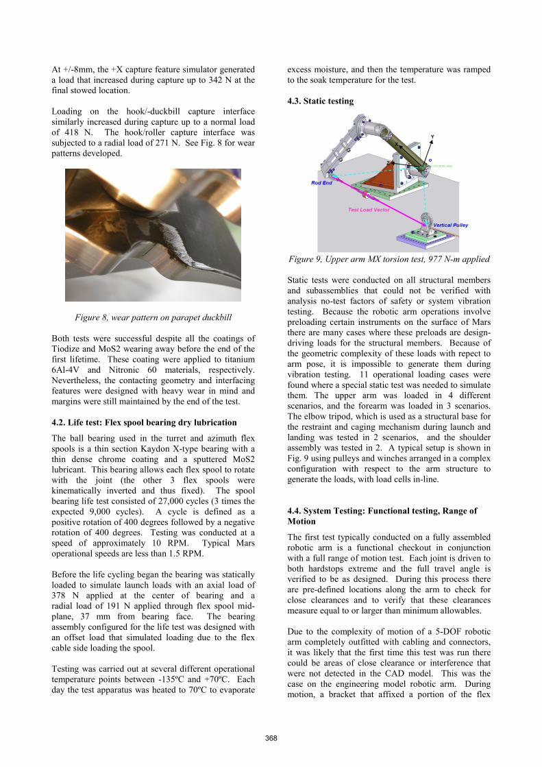
Figure 9, Upper arm MX torsion test, 977 N-m applied
Static tests were conducted on all structural members
and subassemblies that could not be verified with
analysis no-test factors of safety or system vibration
testing. Because the robotic arm operations involve
preloading certain instruments on the surface of Mars
there are many cases where these preloads are design-
driving loads for the structural members. Because of
the geometric complexity of these loads with repect to
arm pose, it is impossible to generate them during
vibration testing. 11 operational loading cases were
found where a special static test was needed to simulate
them. The upper arm was loaded in 4 different
scenarios, and the forearm was loaded in 3 scenarios.
The elbow tripod, which is used as a structural base for
the restraint and caging mechanism during launch and
landing was tested in 2 scenarios, and the shoulder
assembly was tested in 2. A typical setup is shown in
Fig. 9 using pulleys and winches arranged in a complex
configuration with respect to the arm structure to
generate the loads, with load cells in-line.
4.4. System Testing: Functional testing, Range of
Motion
The first test typically conducted on a fully assembled
robotic arm is a functional checkout in conjunction
with a full range of motion test. Each joint is driven to
both hardstops extreme and the full travel angle is
verified to be as designed. During this process there
are pre-defined locations along the arm to check for
close clearances and to verify that these clearances
measure equal to or larger than minimum allowables.
Due to the complexity of motion of a 5-DOF robotic
arm completely outfitted with cabling and connectors,
it was likely that the first time this test was run there
could be areas of close clearance or interference that
were not detected in the CAD model. This was the
case on the engineering model robotic arm. During
motion, a bracket that affixed a portion of the flex
368

cable to the shoulder assembly came to a point of
interference while moving to the azimuth hardstop.
4.5. System Testing: Vibration
The objectives of the vibration test were to verify that
the RA can survive launch, entry, and landing quasi-
static loads and to justify the use of tested factors of
safety. Both random vibration and sine vibration tests
were conducted in 3 axes. Pre-test and post-test low-
level sine-sweeps were conducted to verify that the
structure did not change (i.e., loosen or otherwise shift
in stiffness) during testing. Post-test visual inspection
did not find any anomalies.
4.6. System Testing: Thermal Vacuum
Thermal Vacuum (TVAC) testing was conducted to
validate that the RA design was tolerant to the hot and
cold temperature requirements of the mission, as well
as to characterize the actuators and the effectivity of
the actuator heaters. The proto flight non-operational
temperature range was -135ºC to +70ºC., and the
operational temperature range was were -120ºC to
+50ºC. The robotic arm was also exposed to a
planetary bakeout temperature of +110ºC. Tests were
conducted in the 10 foot diameter chamber at JPL’s
Environmental Test Laboratories. A large chamber
such as this was needed to conduct range of motion
testing. Fig. 10 shows the robotic arm during a dry run
of the TVAC ROM testing performed outside of the
chamber to validate proper motion free of contact with
chamber walls or support structure during actual
TVAC testing.
Figure 10, pre-TVAC ROM testing
During the entire test a flex-cable continuity test was
performed to ensure that the flex-cable system did not
produce any short or open circuits at temperature and
vacuum. To visually monitor the functional testing
four cameras and lights were placed in the chamber.
Thermal cycling started with an initial ramp to +110ºC
bakeoff temperature. To test if the thermal cycling
induced damage or altered the robotic arm hardware in
any way, three thermal cycles between -135ºC and
+70ºC were performed before functional testing
commenced. At the end of the third cold cycle at -
135ºC, the launch lock caging mechanisms were
pyrotechnically released. The caging mechanisms
release was visually confirmed by the 4 cameras and
proven by commanding first motion of the arm, a
smaller subset motion of the aforementioned functional
ROM tests. The robotic arm temperature was then
raised to the cold protoflight operational temperature of
-70ºC. At this temperature a functional ROM was
conducted. During the ROM test, the first few actuator
moves were successful, but when the elbow actuator
was commanded to initialize it did not return telemetry
indicating proper behavior. After a few hours of
trouble-shooting it was discovered that the electronic
ground support equipment (EGSE) was not driving the
encoder circuit with sufficient voltage. External power
supplies were added to the 3 large actuators which
share an identical encoder telemetry circuit and the test
continued without any further encoder issues. The
robotic arm temperature was then raised to the hot
protoflight operational temperature of +70ºC and a
complete functional ROM test was conducted. The
next phase of the TVAC testing continued with thermal
characterization and heater effectivity tests. These tests
were used to characterize the time it takes the actuator
to heat to operational allowable temperatures from the
non-op cold temperature of -120ºC. As each actuator
arrived at its operational temperature of -70ºC a ROM
test was conducted on that particular joint. This tests
the flex cable at that joint at its coldest temperature.
During the heater testing, an open circuit was observed
on the MAHLI camera flex cable. The chamber was
opened for inspection of the robotic arm. After
troubleshooting the flex-cable test setup to verify all
connections were valid, a time domain reflectometer
(TDR) was brought in to try to pinpoint the location of
the open circuit on the 10 m long flex cable. The TDR
found an open in the area of the elbow flex spool
bracket. The flex spool was removed and a damaged
flex cable was found. The damage was caused by a
small protrusion (~1mm) of material that had been
mistakenly left unmachined on the bracket during
manufacturing. The temperature of the flex cable at the
time of the damage was approximately at -120ºC when
the elbow actuator was being moved. At very low
temperature such as this, the non-metallic flex cable
materials are below glass transition temperature. The
damage to the layer of flex-cable had a “shattered”
appearance. Other flex cables that lay on top of the
MAHLI cable had visible deformation but did not
break or cause an open circuit. The MAHLI cable
happens to be the thickest of the flex cables because of
its matched impedance design, so it is prone to higher
bending stresses for a give radius of bend. It was
determined that the cables were damaged beyond a
flight-acceptable repair and needed to be replaced. The
cables were temporarily patched, however, and the
TVAC test was scheduled to continue at a later date.
369

The robotic arm was then delivered to JPL ATLO and
integrated onto the rover for system-level testing.
During the Fall 2010 MSL scheduled rework cycle, the
arm was taken off the rover and the 3 damaged flex
cables were replaced. To verify the fix was successful,
an abridged set of TVAC ROM tests were performed
following installation. This was done to expose the
new flex cables to the same conditions and movements
that caused the first set of cables to fail and verify the
problem had been erradicated. The heater
characterization tests were also completed at this time.
5. LESSONS LEARNED
The Mars Science Laboratory is the most ambitious
Mars mission to date and encompasses countless
subsystems. The main lesson associated with this
project is related to the amount of scope change that
took place over the course of the design. Efficiently
maximizing the design was hindered substantially each
time the scope changed. The two substantial scope
changes were the more than doubling of the turret
instrument mass and tribological issues with the
actuators which lead to a substantial actuator mass
increase. Both had a large effect on the project
progress from design, analysis, and through to
manufacturing.
Having the actuators built by an outside source rather
than designed concurrently by the arm developer
presented additional challenges. As stated previously,
a mass and volume-efficient robotic arm must be
designed as an integrated system, including its
actuators. There were mass and volume inefficiencies
due to additional interfaces needed because of this
disconnect. The whole MSL mission struggled with
this situation of only one manufacturer being
responsible for every actuator on the rover.
The importance of mechanical ground support
equipment (MGSE) cannot be underestimated when a
system is too large to handle by hand. The design,
fabrication, and proof-testing of all the necessary
MGSE for the robotic arm was a very large task,
almost a project unto itself. Another scope change risk
was that the assembly and turn-over fixture was not
sufficiently sized to adequately support the robotic arm
for its full ROM. A complex ROM test had to be
choreographed and analysed so that the stress on the
assembly fixture would be below its structural limits.
This caused issues at time of assembly as well as
during testing because many extra motion command
steps were needed to manipulate the robotic arm to
adhere to load limits. Proof-testing of the MGSE was a
large task because of the large amounts of mass and/or
force that had to be applied. MSL Program delays also
caused many of the proof-test certifications to expire
requiring re-proof testing.
Static testing was another large task that was
underestimated. Because of the nearly unlimited ways
a robotic arm can be oriented, a vibration test cannot
validate the structure for all load cases. Complex
MGSE for static test had to be designed, analyzed,
manufactured, assembled, and proof-tested. This time
and effort were not accounted for in the original scope.
The issues encountered with the flex cable in TVAC
testing were obviously unexpected. The designers and
manufacturing engineers are all very aware of the
functionality of the flex-cable brackets and the need for
them to be smooth and non-binding to the flex-cables.
The problematic bracket, one of hundreds in the
assembly, had a manufacturing defect that was not
found in inspection. The drawings for the bracket were
made using a limited dimensioning scheme which did
not directly provide detail of the area of the defect.
Because of this, the erroneously protruding feature was
not inspected and therefore not detected. Before flex-
brackets are completed, the cabling engineer will
typically inspect by hand all edges of the bracket that
come in contact with the flex cable. The problem was
still not detected however because the defect was
smooth but protruded just enough to catch the edge of
the flex-cables. A procedure to carry out a more
detailed inspection of all flex brackets with the CAD
model will be implemented in the future.
The caging mechanism life tests provided passing
results though with a different outcome than expected.
It was known that the contact stress of these parts
contacting and rubbing would produce debris and wear
the coatings. What was unclear before the test was
how much debris would be generated and how much of
the actual metal would be worn away. The passing
criterion for the mechanism was that the torque
required to cycle the caging mechanism be below a
specified threshold, approximately a tenth of the
actuators stall torque. Studying the torque numbers
over the life test revealed that the torque used went up
and down fairly cyclical over the course of the life test.
It was surmised that the rise of the torque was caused
when the two contacting surfaces were directly
abrading the metal. When the required torque
underwent a downward trend it was surmised that the
two contacting surfaces were riding on the abraded
debris which acted like ball bearings introducing
rolling motion characteristics. As previously discussed,
this was a worst-case test with full-load contact derived
from worst-case misalignment imposed on every test
cycle. Re-stowing the robotic arm under laboratory
conditions has demonstrated very little contact of the
interfacing caging surfaces and no abrasions to date.
6. CONCLUSIONS
The 4 year project has been a success so far with only a
few anomalies on the way. Lessons learned will be
used to plan and carry out future projects in a more
efficient process. But the project won’t be over until
the robotic arm has been deployed successfully on the
surface of Mars.
370


![Hydraulic Robotic Arm[1]](https://static.fdocuments.net/doc/165x107/577c83d31a28abe054b667dc/hydraulic-robotic-arm1.jpg)