Markus Bartscher, Ulrich Neuschaefer-Rube, Marko … · DTI, Taastrup, 31. May 2011 - 1 - Markus...
18
DTI, Taastrup, 31. May 2011 -1- Markus Bartscher , Ulrich Neuschaefer-Rube, Marko Neukamm, Matthias Schulze Physikalisch-Technische Bundesanstalt Braunschweig and Berlin, Germany Andreas Staude, Jürgen Goebbels, Karsten Ehrig Federal Institute for Materials Research and Testing, Berlin, Germany Aspects of traceability of dimensional CT measurements
Transcript of Markus Bartscher, Ulrich Neuschaefer-Rube, Marko … · DTI, Taastrup, 31. May 2011 - 1 - Markus...
DTI, Taastrup, 31. May 2011 - 1 -
Markus Bartscher, Ulrich Neuschaefer-Rube, Marko Neukamm, Matthias Schulze
Physikalisch-Technische BundesanstaltBraunschweig and Berlin, Germany
Andreas Staude, Jürgen Goebbels, Karsten Ehrig
Federal Institute for Materials Researchand Testing, Berlin, Germany
Aspects of traceability of dimensional CT measurements

DTI, Taastrup, 31. May 2011 - 2 -
1. IntroductionPTB – German national metrology instituteTraceability
2. Aspects of traceability of dimensional CTDismountable reference standardTactile measurements of freeforms Actual-nominal value comparisonsModeling for enhanced probing
3. Short Outlook: reference standards for micro CTMicrotetrahedrons as reference standardsApplication of microtetrahedrons
4. Conclusions
Content

DTI, Taastrup, 31. May 2011 - 3 -
Braunschweig
Berlin-Charlottenburg
PTB-lab at BESSY II in Berlin-Adlershof
Physikalisch-Technische Bundesanstalt
Metrology light sourceMLS in Berlin-Adlershof
PTB – German national metrology institute
DTI, Taastrup, 31. May 2011 - 4 -
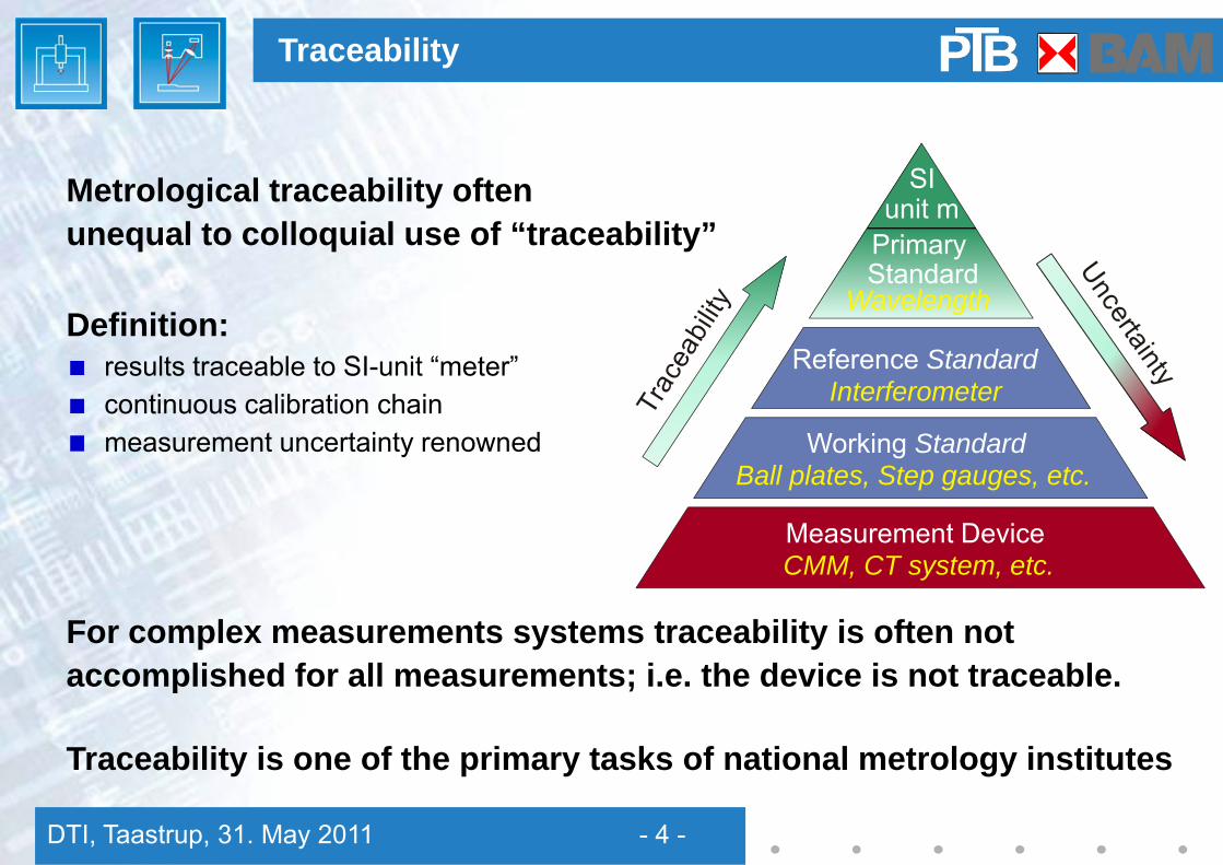
Metrological traceability oftenunequal to colloquial use of “traceability”
Definition:results traceable to SI-unit “meter”continuous calibration chain measurement uncertainty renowned
For complex measurements systems traceability is often not accomplished for all measurements; i.e. the device is not traceable.
Traceability is one of the primary tasks of national metrology institutes
Traceability
PrimaryStandard
Wavelength
Reference StandardInterferometer
Working StandardBall plates, Step gauges, etc.
Measurement DeviceCMM, CT system, etc.
SIunit m

DTI, Taastrup, 31. May 2011 - 5 -
NIKON Metrology XT H 225 ST CT systemX-ray tube with two X-ray heads:225 kV 225 W reflection target225 kV 20 W transmission target2k x 2k PerkinElmer 1620 (detector size 400 mm) Axes with linear scalesFast reconstruction (5-10 min) 225 kV rotational target 640 W in aquisition
PTB CT system in Braunschweig
Ion trapCT measurement
(J. Wübbena,PTB, QUEST)
DTI, Taastrup, 31. May 2011 - 6 -
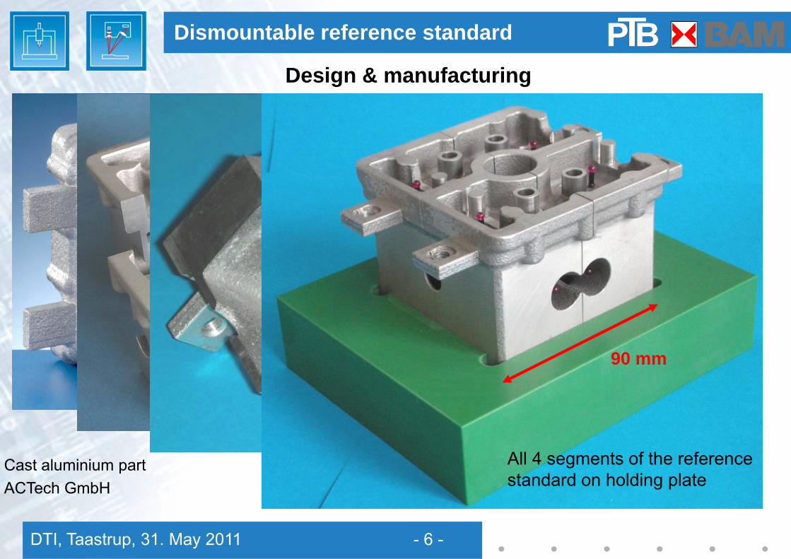
Design & manufacturing
Dismountable reference standard
90 mm
90 mm
All 4 segments of the reference standard on holding plate
Cast aluminium partACTech GmbH
DTI, Taastrup, 31. May 2011 - 7 -
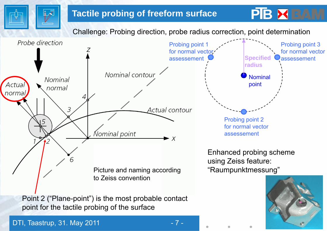
Tactile probing of freeform surface
Challenge: Probing direction, probe radius correction, point determination
Point 2 (“Plane-point”) is the most probable contact point for the tactile probing of the surface
Picture and naming according to Zeiss convention
Nominal point
Probing point 2for normal vector assessement
Probing point 3for normal vector assessementSpecified
radius
Probing point 1for normal vector assessement
Enhanced probing scheme using Zeiss feature: “Raumpunktmessung”

DTI, Taastrup, 31. May 2011 - 8 -
Results of iterative probing scheme
Tripod radius of 0.5 mm
one pointsuspicous(unstable)
Consequences
Iterative probing success can be controlled
Further analysis with a variable tripod necessary
“Plane” approach may fail at certain critical points
Tactile Probing with plane approximation
Effect in probing direction
For tripod radius 0.5 mm average lateral shift: 25 µm
Iteratively measured points shift lateral on surface→ effect of topology, sphere diameter and strategy
Unstable point shows:150 µm lateral shift
Effect perpendicular to probing direction

DTI, Taastrup, 31. May 2011 - 9 -
Proper actual-nominal value comparisons
Excursus: Comparisons
Dstandard
Standard (false) scheme:Tactile CMM measurement pointset as actual and surface set as reference (nominal value)
Dcorrect
Correct scheme:Tactile CMM measurement point and assessed surface vector set as reference(nominal value) and surface set as actual
|Dcorrect| ≠ |Dstandard|
Solution for applying the correct scheme:
Use appropriate CMM measurement & actual-nominal comparison (inspection) software:Here, ATOS 6.2 (GOM Corp., Germany) is used (data analysis Dr. Thesing, GOM)or use successor software GOM Inspect

DTI, Taastrup, 31. May 2011 - 10 -
red: CT (reference) - tactile (actual)black: tactile with normal vector (reference) - CT (actual)
Measurement result:6 CT measurements, 205 kV – 210 kV, (48 µm)3 – (105 µm)3 voxel size, analyzedat 29-35 points, iterative tactile probing
Results of CT
-0,040
-0,030
-0,020
-0,010
0,000
0,010
0 50 100 150 200
data point No.
diffe
renc
e in
mm
Difference between false and correctcomparison scheme (difference betweendeviations „red minus black“)
DTI, Taastrup, 31. May 2011 - 11 -
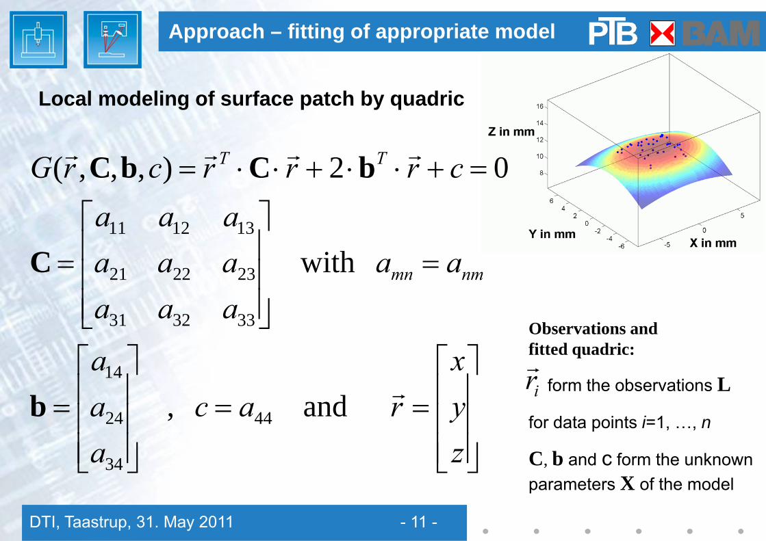
Local modeling of surface patch by quadric
Approach – fitting of appropriate model
⎥⎥⎥
⎦
⎤
⎢⎢⎢
⎣
⎡==
⎥⎥⎥
⎦
⎤
⎢⎢⎢
⎣
⎡=
=⎥⎥⎥
⎦
⎤
⎢⎢⎢
⎣
⎡=
=+⋅⋅+⋅⋅=
zyx
racaaa
aaaaaaaaaaa
crrrcrG
nmmn
TT
r
rrrr
and ,
with
02),,,(
44
34
24
14
333231
232221
131211
b
C
bCbC
Observations and fitted quadric:
form the observations L
for data points i=1, …, n
C, b and c form the unknown parameters X of the model
irr

DTI, Taastrup, 31. May 2011 - 12 -
Mathematical formulation – fitting of quadric to surface point data
Fitting of quadric to data points
0),,,( =crG ii bCr
0),(ˆ)ˆ,ˆ( 0 =+⋅+⋅= XLxAvBXL FF0ˆˆ XXx −=
( )LLv −= ˆ
),( 0XLF
min2 →∑i
iv
)ˆ,ˆ(2 XLkvv FΩ TT ⋅⋅−=Implementation in MATLAB R2009a (using standard modules only)
with korrelates k
for i = 1,⋅⋅⋅, n
the reduced parameter vector
the vector of residuals
the inconsistency values
Linearization (Gauß-Helmert)
DTI, Taastrup, 31. May 2011 - 13 -
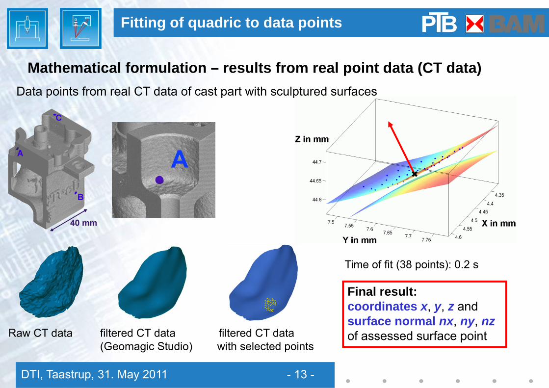
Time of fit (38 points): 0.2 s
Mathematical formulation – results from real point data (CT data)Data points from real CT data of cast part with sculptured surfaces
Fitting of quadric to data points
Raw CT data filtered CT data filtered CT data (Geomagic Studio) with selected points
Final result:coordinates x, y, z andsurface normal nx, ny, nzof assessed surface point

DTI, Taastrup, 31. May 2011 - 14 -
buuu wpcalkU 2222 +++=
Update of ISO 15530-3 treatment of systematic errors (ISO TC 213 WG10)
rewritten formula conformant to GUM
Procedure of ISO 15530-3:2004 for uncorrected systematic errorswas not consistent with GUM
Empirical assessment of uncertainty
Additional treatment of uncorrected systematic errors b in upcoming VDI/VDE 2630-2.1 draft
uuuu bwpcalkU 2222 +++= rewritten formula conformant to GUM
UbyY ±−=According to GUM systematic error bhas to be corrected and to be stated in the result Y

DTI, Taastrup, 31. May 2011 - 15 -
Task specific microtetradheron standards (made by PTB)
Reference standards for micro CT
Microtetrahedrons with stepped size with 4 ruby sphere, respectively
Microtetrahedrons with 3 ruby spheres and one sphere of different material (all Ø 0.5 mm)
SiN Steel ZrO2
Ø 3.0 mm Ø 2.0 mm Ø 1.0 mm Ø 0.5 mm Ø 0.3 mm Ø 0.2 mm
Manufacturing of tetrahedronsDr. R. Meeß, J. Brzoska, A. Jung (PTB)
Ruby
DTI, Taastrup, 31. May 2011 - 16 -
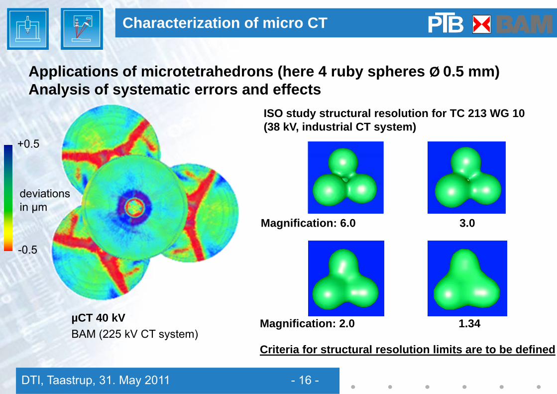
Applications of microtetrahedrons (here 4 ruby spheres Ø 0.5 mm)Analysis of systematic errors and effects
ISO study structural resolution for TC 213 WG 10 (38 kV, industrial CT system)
-0.5
+0.5
µCT 40 kVBAM (225 kV CT system)
deviationsin µm
Characterization of micro CT
Criteria for structural resolution limits are to be defined
Magnification: 2.0 1.34
Magnification: 6.0 3.0

DTI, Taastrup, 31. May 2011 - 17 -
Traceability is the core objective for any measurement technique
Certain aspects and challenges have been addressed for CT systems:- use of dismountable reference standard- correct calibration & analysis of freeforms and assessed datasets- enhanced probing scheme for freeform surfaces- treatment of systematic errors according to ISO 15530 & VDI 2630-2.1
Micro CT requires dedicated reference standards, e.g. tetrahedrons.Applications of standards up to now can be theanalysis of systematic effect, system approvaland structural resolution analysis
Conclusions
DTI, Taastrup, 31. May 2011 - 18 -
Contact:[email protected]
Thank you for your attention!
The authors thank for their contribution
Christoph KuhnAndreas Deffner
Andreas Knoch
Michael Krystek
Jan Thesing
Activities supported by the German Research Foundation (DFG) projectNo. NE 757/2-2 and by the German Federal Ministry of Economics & Technology project No. AZ:II D5 –07/06