markilux pavilion / frame system markilux...
29
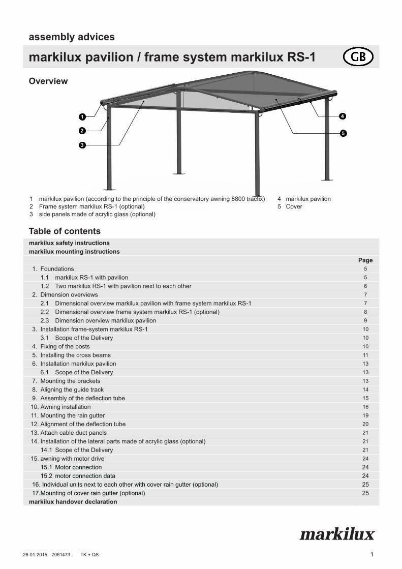
1 Overview markilux markilux pavilion / frame system markilux RS-1 assembly advices Table of contents markilux safety instructions markilux mounting instructions Page 1. Foundations 5 1.1 markilux RS-1 with pavilion 5 1.2 Two markilux RS-1 with pavilion next to each other 6 2. Dimension overviews 7 2.1 Dimensional overview markilux pavilion with frame system markilux RS-1 7 2.2 Dimensional overview frame system markilux RS-1 (optional) 8 2.3 Dimension overview markilux pavilion 9 3. Installation frame-system markilux RS-1 10 3.1 Scope of the Delivery 10 4. Fixing of the posts 10 5. Installing the cross beams 11 6. Installation markilux pavilion 13 6.1 Scope of the Delivery 13 7. Mounting the brackets 13 8. Aligning the guide track 14 9. Assembly of the deflection tube 15 10. Awning installation 16 11. Mounting the rain gutter 19 12. Alignment of the deflection tube 20 13. Attach cable duct panels 21 14. Installation of the lateral parts made of acrylic glass (optional) 21 14.1 Scope of the Delivery 21 15. awning with motor drive 24 15.1 Motor connection 24 15.2 motor connection data 24 16. Individual units next to each other with cover rain gutter (optional) 25 17.Mounting of cover rain gutter (optional) 25 markilux handover declaration 26-01-2015 7061473 TK + QS 1 2 3 4 5 1 markilux pavilion (according to the principle of the conservatory awning 8800 tracfix) 4 markilux pavilion 2 Frame system markilux RS-1 (optional) 5 Cover 3 side panels made of acrylic glass (optional)
Transcript of markilux pavilion / frame system markilux...
1
Overview
markilux
markilux pavilion / frame system markilux RS-1assembly advices
Table of contentsmarkilux safety instructionsmarkilux mounting instructions
Page1. Foundations 5
1.1 markilux RS-1 with pavilion 51.2 Two markilux RS-1 with pavilion next to each other 6
2. Dimension overviews 72.1 Dimensional overview markilux pavilion with frame system markilux RS-1 72.2 Dimensional overview frame system markilux RS-1 (optional) 82.3 Dimension overview markilux pavilion 9
3. Installation frame-system markilux RS-1 103.1 Scope of the Delivery 10
4. Fixing of the posts 105. Installing the cross beams 116. Installation markilux pavilion 13
6.1 Scope of the Delivery 137. Mounting the brackets 138. Aligning the guide track 149. Assembly of the deflection tube 15
10. Awning installation 1611. Mounting the rain gutter 1912. Alignment of the deflection tube 2013. Attach cable duct panels 2114. Installation of the lateral parts made of acrylic glass (optional) 21
14.1 Scope of the Delivery 2115. awning with motor drive 24
15.1 Motor connection 2415.2 motor connection data 24
16. Individual units next to each other with cover rain gutter (optional) 2517.Mounting of cover rain gutter (optional) 25
markilux handover declaration
26-01-2015 7061473 TK + QS
1
2
3
4
5
1 markilux pavilion (according to the principle of the conservatory awning 8800 tracfix) 4 markilux pavilion2 Frame system markilux RS-1 (optional) 5 Cover3 side panels made of acrylic glass (optional)


markilux safety instructionsImportant information for the installation of markilux awnings
markilux
If the awning construction has to be pulled up into a higher area with rope support, then the awning has• to be taken out of the package,• should be connected with pull ropes in such a way that these
cannot slip out,• are to be pulled up up evenly in an horizontal position.
The same also applies for awning deinstallation.
Working at heights increases the risk of falling.Appropriate climbing aids and safety rails are to be used whilst
installing the awning.
5. Wind resistance classes
markiluxSchmitz-Werke GmbH & Co. KG
Hansestraße 87D-48282 Emsdetten
DIN EN 13561Awnings for exterior applications
wind resistance class 2markilux folding-arm awningsmarkilux 710/810, 720/820, 725/825, 750/850, 730/830, 740/840, 745/845, 893, 869/869 zip/889/889 zip (depending on size), 8850
wind resistance class 3markilux 760/860, 620 zip, 660 zip, 680 zip, 780/880, 8800/8800 zip, 869/869 zip/889/889 zip (depending on size), pergola 110/210
The awning fulfills the requirements of the wind resistance class specified in the CE conformity marking (explanations see „handover declaration“).In assembled condition, it only fulfills these requirements if...• ... the awning is mounted in accordance with the type and number
of consoles recommended by the manufacturer.• ... the instructions of the fixing material manufacturer regarding the
used dowels were followed during the assembly.• ... the installation of folding-arm awnings was carried out
considering the
1.Who is allowed to fit markilux awnings?The markilux installation instructions are to a qualified mechanic who has skilled knowledge in following domains:• Occupational and operational safety and accident prevention
regulations• Handling of ladders and scaffoldings• Handling and transport of long and heavy component parts• Handling of tools and machines• Fixture device placement• Assessment of building materials• Commissioning and operation of the productIf any one of these qualifications is not existent, a qualified installation firm must be engaged.
Electrical works: electrical installations must be carried out by a certified electrician according to VDE 0100. The enclosed
installation instructions of the supplied electronic devices are to be observed. We recommend installation be carried out by at least two people. Larger awnings may require three persons.
2. Before beginning the installation it is to be checked, ...• does the number and type of fixture brackets match the order?• do the specifications made with the order concerning the fastening
background correspond with the actual fastening background at hand (only for folding-arm awnings)?
If irregularities which may affect the safety of the unit or its users are determined, then the installation must not be undertaken.
3. Reading and passing on the instructions
The security and attachment notes as well as the operation manuals are to be read and observed!The markilux operating guide, as well as the setting instructions of the motor, switch and controller manufacturers are to be handed over to the user with a written confirmation and fitted wind class (see handover declaration). He is to be comprehensively informed about the safety and usage information of the awning. With nonobservance and improper operation, the awning can suffer damage and accidents can occur.
4. Working at greater heights
www.markilux.com
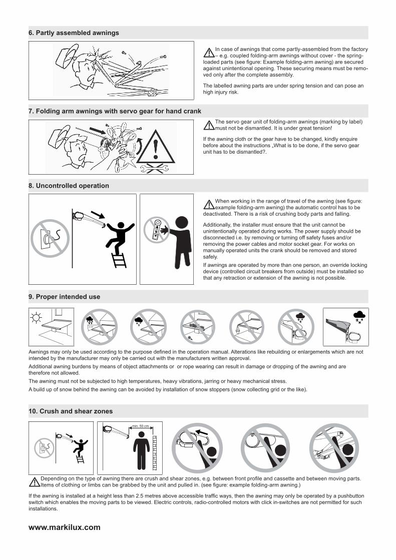
8. Uncontrolled operation
When working in the range of travel of the awning (see figure: example folding-arm awning) the automatic control has to be
deactivated. There is a risk of crushing body parts and falling.
Additionally, the installer must ensure that the unit cannot be unintentionally operated during works. The power supply should be disconnected i.e. by removing or turning off safety fuses and/or removing the power cables and motor socket gear. For works on manually operated units the crank should be removed and stored safely.If awnings are operated by more than one person, an override locking device (controlled circuit breakers from outside) must be installed so that any retraction or extension of the awning is not possible.
9. Proper intended use
10. Crush and shear zones
The servo gear unit of folding-arm awnings (marking by label) must not be dismantled. It is under great tension!
If the awning cloth or the gear have to be changed, kindly enquire before about the instructions „What is to be done, if the servo gear unit has to be dismantled?.
7. Folding arm awnings with servo gear for hand crank
6. Partly assembled awnings
In case of awnings that come partly-assembled from the factory – e.g. coupled folding-arm awnings without cover - the spring-
loaded parts (see figure: Example folding-arm awning) are secured against unintentional opening. These securing means must be remo-ved only after the complete assembly.
The labelled awning parts are under spring tension and can pose an high injury risk.
0-14°
Awnings may only be used according to the purpose defined in the operation manual. Alterations like rebuilding or enlargements which are not intended by the manufacturer may only be carried out with the manufacturers written approval.Additional awning burdens by means of object attachments or or rope wearing can result in damage or dropping of the awning and are therefore not allowed.The awning must not be subjected to high temperatures, heavy vibrations, jarring or heavy mechanical stress.A build up of snow behind the awning can be avoided by installation of snow stoppers (snow collecting grid or the like).
min. 50 cm
Depending on the type of awning there are crush and shear zones, e.g. between front profile and cassette and between moving parts. Items of clothing or limbs can be grabbed by the unit and pulled in. (see figure: example folding-arm awning.)
If the awning is installed at a height less than 2.5 metres above accessible traffic ways, then the awning may only be operated by a pushbutton switch which enables the moving parts to be viewed. Electric controls, radio-controlled motors with click in-switches are not permitted for such installations.

5
www.markilux.com
1. Foundations
dimensions in cm
1.1 markilux RS-1 with pavilion
markilux pavilion / frame system markilux RS-1assembly advices
90
95
80
95
85
85
F1
BG
H GB
GH
= A
H +
h
AH
D
H
SAMb
M
RR
F1
F1
SAMa
AR
R
L
ST
hOn site the following have to be prepared as per drawing below every post:
• Concrete foundations (F1) of concrete compressive strength C 25/30 (previously B25) with rebar matting basket made of rebar matting Q188.
• Base plates (F1) to be fixed using Fischer stainless steel anchor bolts FAZ II 16/50 in A4 stainless steel with washer acc. to DIN 9021 (or equivalent). Observe mounting instructions by the respective manufacturer!
SAMa [mm) h [mm]4000 5144100 5244200 5354300 5464400 5564500 5674600 5784700 5884800 5994900 6095000 620
M = overall blind widthH = drop markilux pavillion = SAMa + 576 mmh = gable heightAH = height frame system = DH + 100 mmAR = extension directionF1 = concrete foundation
DH = clearance height (2500 mm standard, optional max. 3200 mm)
GH = overall height = AH + h
GB = overall width = SAMb + 234 mmL = leftM = motor drive right or leftRR = front gutterR = right
SAMa = post separation, centre to centre in extension direction = H - 576 mm
SAMb = post separation, centre to centre in width direction = GB - 234 mm
ST = lateral parts made of acrylic glass (optional)
6
www.markilux.com
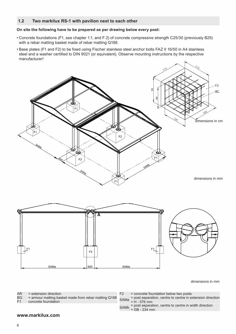
1.2 Two markilux RS-1 with pavilion next to each other
On site the following have to be prepared as per drawing below every post:
• Concrete foundations (F1, see chapter 1.1, and F 2) of concrete compressive strength C25/30 (previously B25) with a rebar matting basket made of rebar matting Q188.
• Base plates (F1 and F2) to be fixed using Fischer stainless steel anchor bolts FAZ II 16/50 in A4 stainless steel and a washer certified to DIN 9021 (or equivalent). Observe mounting instructions by the respective manufacturer!
600
SAMa
SAMa
SAMb
F1
F2
F1
F1
F1
F2
90
115
80
115
105
105
F2
BG
SAMa 600 SAMa
A
F1 F1F2
dimensions in mm
dimensions in cm
SAMa 600 SAMa
A
F1 F1F2
dimensions in mm
AR = extension directionBG = armour matting basket made from rebar matting Q188F1 concrete foundation
F2 = concrete foundation below two posts
SAMa = post separation, centre to centre in extension direction = H - 576 mm
SAMb = post separation, centre to centre in width direction = GB - 234 mm
7
www.markilux.com
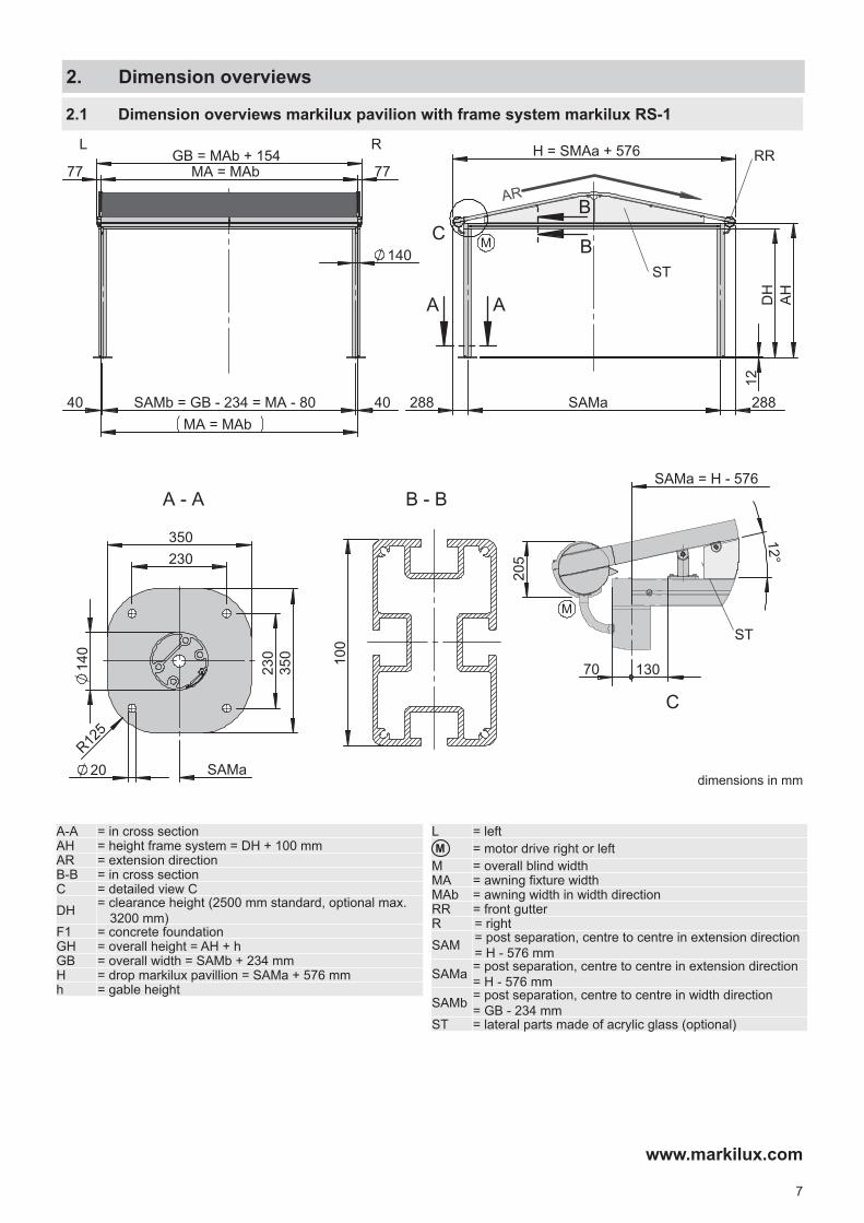
2.1 Dimension overviews markilux pavilion with frame system markilux RS-1
GB = MAb + 154 MA = MAb 77 77
R L
DH
1
2
AH
H = SMAa + 576
SAMa 288 288
A
C
AR
SAMa = H - 576
40
BM
A
B
140
350
2
30
350 230
14
0
SAMa
SAMb = GB - 234 = MA - 80 40 MA = MAb
R12
5
20
100
12°
205
130
C
M
70
M
RR
ST
B - B A - A
ST
dimensions in mm
2. Dimension overviews
A-A = in cross sectionAH = height frame system = DH + 100 mmAR = extension directionB-B = in cross sectionC = detailed view CDH = clearance height (2500 mm standard, optional max.
3200 mm)F1 = concrete foundationGH = overall height = AH + hGB = overall width = SAMb + 234 mmH = drop markilux pavillion = SAMa + 576 mmh = gable height
L = leftM = motor drive right or leftM = overall blind widthMA = awning fixture widthMAb = awning width in width directionRR = front gutterR = rightSAM = post separation, centre to centre in extension direction
= H - 576 mmSAMa = post separation, centre to centre in extension direction
= H - 576 mmSAMb = post separation, centre to centre in width direction
= GB - 234 mmST = lateral parts made of acrylic glass (optional)
8
www.markilux.com
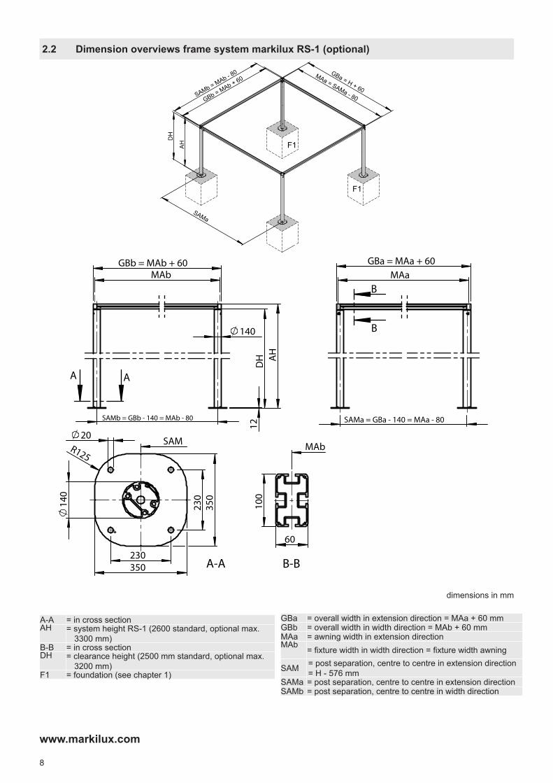
2.2 Dimension overviews frame system markilux RS-1 (optional)
AH
DH
MAa = SAMa - 80
GBa = H + 60
SAMa
GBb = MAb + 60
SAMb = MAb - 80
F1
F1
140
DH
1
2
AH
SAMb = GBb - 140 = MAb - 80
MAb GBb = MAb + 60
A A
350
350
230
R125
230
SAM
14
0
20
A-A
SAMa = GBa - 140 = MAa - 80
GBa = MAa + 60 MAa
B
B
100
60
MAb
B-B
dimensions in mm
A-A = in cross sectionAH = system height RS-1 (2600 standard, optional max.
3300 mm)B-B = in cross sectionDH = clearance height (2500 mm standard, optional max.
3200 mm)F1 = foundation (see chapter 1)
GBa = overall width in extension direction = MAa + 60 mmGBb = overall width in width direction = MAb + 60 mmMAa = awning width in extension directionMAb = fixture width in width direction = fixture width awning
SAM = post separation, centre to centre in extension direction = H - 576 mm
SAMa = post separation, centre to centre in extension directionSAMb = post separation, centre to centre in width direction

9
www.markilux.com
2.3 Dimension overview markilux pavilion
MA = awning width between fixture points = fixture width = overall width - 154 mm = order width
H = drop markilux pavilion = order widthGB = overall width
= awning width between fixture points + 154 mmh = gable heightDH = clearance height (2500 mm standard, optional max.
3200 mm)AR = extension direction
dimensions in mm
AR
RR
R
L
MA = GB - 154
H
GB h
H - 400
M
GB MA = GB - 154
200 H - (2 x 200)
A
M
H h M
55
12°
68
205
M
H
M
A ARL RRR
RR = front gutterM = motor drive right or leftR = rightL = leftA = detailed view

10
www.markilux.com
3. Installation frame system markilux RS-1
1. Lay concrete foundations (F1) with reinforcement cage (BG) (see chapter 1. Foundations). Observe post clearances SAMa and SAMb!
90
95
80
95
85
85
F1
BG
2. Align the base plates to each other (SAMa and SAMb). Measure the posts diagonally (1 / 2) (cord pulley d1 = d2). Align the posts vertically and at the same height. Pay attention to point 3 here.
SAMb SAMa
d1 d2
2
1
1
2
3.1 Delivery state
4. Fixing of the posts
2
1
3
1
2
1 / 2 = post assembly3 = cross beam4 = pincher carriage M 105 = insertion plate6 = washer7 = cylindrical head screw M 10 x 408 = cylindrical head screw M 10 x 409 = washer
74 5
8
6
9
Dimensions in cm
11
www.markilux.com
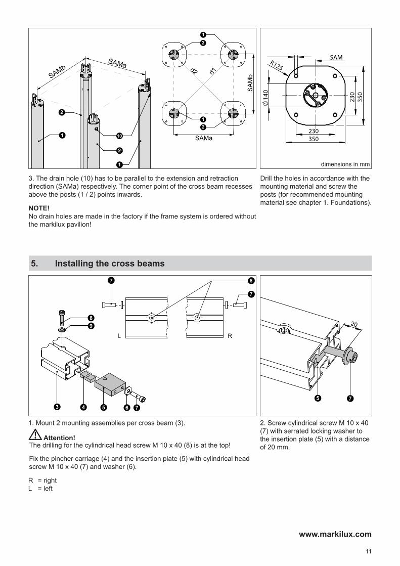
1. Mount 2 mounting assemblies per cross beam (3). 2. Screw cylindrical screw M 10 x 40 (7) with serrated locking washer to the insertion plate (5) with a distance of 20 mm.
3 4 5 7
8
6
9 20
5 7
L R
7 8
7
Drill the holes in accordance with the mounting material and screw the posts (for recommended mounting material see chapter 1. Foundations).
3. The drain hole (10) has to be parallel to the extension and retraction direction (SAMa) respectively. The corner point of the cross beam recesses above the posts (1 / 2) points inwards.
NOTE!No drain holes are made in the factory if the frame system is ordered without the markilux pavilion!
101
2
2
1
SAMbSAMa
d1
d2
SAMa
21
SA
Mb
12
350
350
230
R125
230
SAM
14
0 5. Installing the cross beams
Fix the pincher carriage (4) and the insertion plate (5) with cylindrical head screw M 10 x 40 (7) and washer (6).
R = rightL = left
The drilling for the cylindrical head screw M 10 x 40 (8) is at the top! Attention!
dimensions in mm
12
www.markilux.com
11
1/2
7
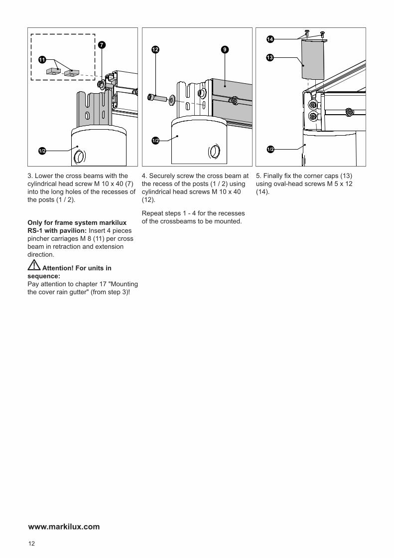
3. Lower the cross beams with the cylindrical head screw M 10 x 40 (7) into the long holes of the recesses of the posts (1 / 2).
Only for frame system markilux RS-1 with pavilion: Insert 4 pieces pincher carriages M 8 (11) per cross beam in retraction and extension direction.
Attention! For units in sequence:Pay attention to chapter 17 "Mounting the cover rain gutter" (from step 3)!
12
1/2
9
4. Securely screw the cross beam at the recess of the posts (1 / 2) using cylindrical head screws M 10 x 40 (12).
Repeat steps 1 - 4 for the recesses of the crossbeams to be mounted.
5. Finally fix the corner caps (13) using oval-head screws M 5 x 12 (14).
13
14
1/2

13
www.markilux.com
18
165
SAMa
14
13
5/6117
16
18
SAMa
5
6
1. Fix brackets (5) at the pincher carriage M8 previously inserted into the cross beam (see chapter 5.3) using hexagon screws M 8 x 25 (6) so that they can still be moved.
203
SAMa
SAMb
6
5
2. Mount brackets (5) with a distance of 203 mm to the cross beam (SAMb direction).
18
165
SAMa
14
13
5/6117
16
18
6. Installation markilux pavilion
6.1 Delivery state
4
31
2
1 = guide track2 = awning3 = deflection tube4 = front gutter
7. Mounting the brackets
SAMa = post separation, centre to centre in extension directionSAMb = post separation, centre to centre in width direction
NOTE! The following installation steps apply for the left and right side respectively!

14
www.markilux.com
SAMa
M
SAMa
RRRR
==
5 5
1
5
1
Put the guide rail (1) in place and bolt with the brackets (5). Ensure that the centre drilling below the guide rail is centred to the cross beam.
dimensions in mm
Do not remove the protective foil of the front profile and the transport belt fixings (2 - adhesive strips, 4 - Styrofoam wedges) from the guide tracks (1).
8. Align the guide tracks
Attention!
M = motor drive right or leftSAMa = post separation, centre to centre in extension direction
RR = front gutter

15
www.markilux.com
10
3
9
3. Align the deflection tube (3) approx. 10 mm next to the belt exit. Tighten the hexagonal bolts M 6 x 40 (8). Unscrew clamping screw (35).
8
3
ca. 10 mm
35
4. Remove the fixation (tape) of the belt (9). Loosen countersunk head screws M 4 x 12 (10).
5. Thread in the end of the belt (9). Tighten the countersunk head screws M 4 x 12 (10) by hand. Push the protruding belt completely into the oblong hole (36) of the deflection tube and mount the clamping screw (35) again.
10
3
9
36
9. Mounting the deflection tube
3
1. Fix the deflection tube (3) centred to the guide rails (1).
7
3
2. Let the clamping jaws (7) of the deflection tube recesses engage into the groove of the guide rails (1).
3 77
1
NOTE! The following installation steps apply for the left and right side respectively!

16
www.markilux.com
10. Awning installation
12
13
1. Unpack the awning from the box (pay attention to marking "top")! Remove the the protective film (11) of the front profile.
11
2. Unscrew the countersunk head screw 4.2 x 13 (12) at the inspection cover (13) and remove inspection cover.
For awnings with tracfix system, the cover has to be threaded in the plastic track (18) with the "zip" (17) beforehand.
18
17
3. Loosely slide the end cap (14) for about 2 to 3 cm into the guide track (1). Remove the tape holding the drive belt in place (adhesive strip) from the guide track profile. The lug-end of the drive belt (15) must be fed over the belt roller (16).
1
15
16
14
4. Push the awning up to the stop into the guide track (1) and secure with a SW 13 cylindrical head screw M 8 x 60 (19).
19
1
19
NOTE! The following installation steps apply for the left and right side respectively!
3a. Attention!

17
www.markilux.com
2120
5. Lift the lug-end of the drive belt (15) up. Guide the assembly aid (21) between the fabric roller (20) and the rear of the cassette with the thicker part facing up.
211520
6. Push the assembly aid (15) through and guide around the fabric roller (20).
7. Push the lug-end of the drive belt (15) through the slot in the assembly aid (21).
21
15
229229
15
8. Pull the assembly aid (21) back out. In so doing the drive belt (9) is guided around the underside of the fabric roller (20). Detach the lug-end of the drive belt (15) from the assembly aid.
21
209
15
Slip the lug-end of the drive belt (15) underneath the first wrap of drive belt (9) and insert it into the groove in the fabric roller (22).
Do not twist the transport bands!
The drive belt has to be passed around the fabric roller a second time, so push the assembly aid through again and repeat steps 5. to 8.
Ensure that the belt rolls up cleanly on itself on the fabric roller (20). Do not twist the drive belt (9)! Repeat points 2. to 10. at the right side.
10. Attention!
Attention!
Attention!
18
www.markilux.com
125
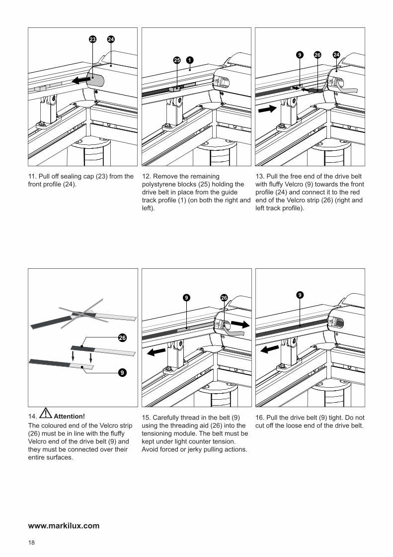
11. Pull off sealing cap (23) from the front profile (24).
2423
12. Remove the remaining polystyrene blocks (25) holding the drive belt in place from the guide track profile (1) (on both the right and left).
13. Pull the free end of the drive belt with fluffy Velcro (9) towards the front profile (24) and connect it to the red end of the Velcro strip (26) (right and left track profile).
249 26
16. Pull the drive belt (9) tight. Do not cut off the loose end of the drive belt.
99 26
26
9
15. Carefully thread in the belt (9) using the threading aid (26) into the tensioning module. The belt must be kept under light counter tension. Avoid forced or jerky pulling actions.
14. Attention!The coloured end of the Velcro strip (26) must be in line with the fluffy Velcro end of the drive belt (9) and they must be connected over their entire surfaces.
19
www.markilux.com
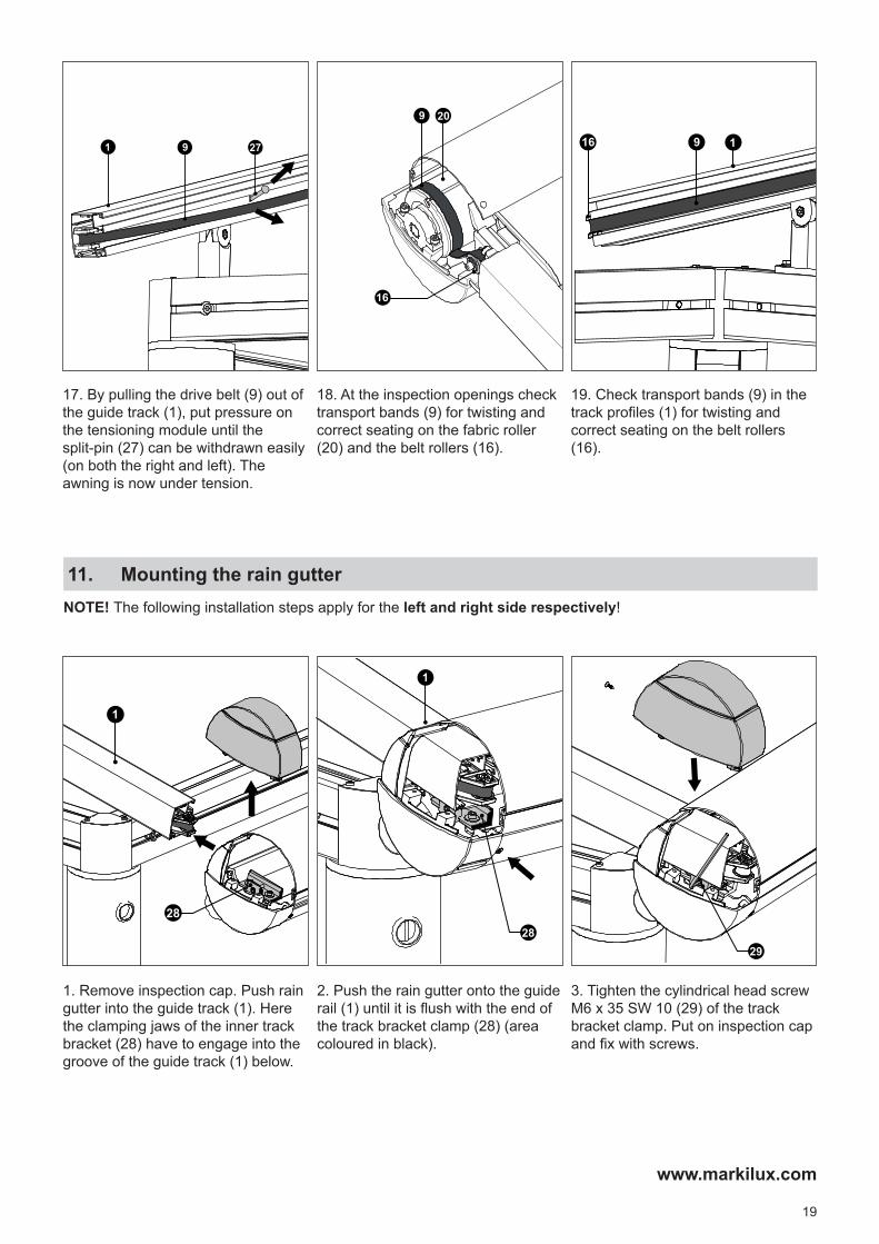
19. Check transport bands (9) in the track profiles (1) for twisting and correct seating on the belt rollers (16).
916 1
209
16
17. By pulling the drive belt (9) out of the guide track (1), put pressure on the tensioning module until the split-pin (27) can be withdrawn easily (on both the right and left). The awning is now under tension.
1 279
18. At the inspection openings check transport bands (9) for twisting and correct seating on the fabric roller (20) and the belt rollers (16).
11. Mounting the rain gutter
28
1
1. Remove inspection cap. Push rain gutter into the guide track (1). Here the clamping jaws of the inner track bracket (28) have to engage into the groove of the guide track (1) below.
1
28
2. Push the rain gutter onto the guide rail (1) until it is flush with the end of the track bracket clamp (28) (area coloured in black).
NOTE! The following installation steps apply for the left and right side respectively!
29
3. Tighten the cylindrical head screw M6 x 35 SW 10 (29) of the track bracket clamp. Put on inspection cap and fix with screws.

20
www.markilux.com
5. Mount the water spout with oval-head self-tapping screws 4.8 x 16 (32) and intermediate seal at the cassette.
32
12. Align deflection tube (tension belt)
3. Maintain tension and tighten well the countersunk head screws M 4 x 12 (10). Secure the clamping screw (35) with medium-strength adhesive for locking screws and tighten well. Extend the awning completely.
Attention: The cover seam has to be centred on the deflection tube.
10359
10
3
1. Conduct a test run of the awning and stop approx. 50 cm prior to reaching the end position. The deflection tube (3) starts to swivel upwards.
3
9
2. Slightly loosen countersunk head screws M 4 x 12 (10) and pull drive belt (9) under tension through the clamp.
NOTE! The following installation steps apply for the left and right side respectively!
4. Insert the water spout (31) into the drilling at the posts.
31
21
www.markilux.com
13. Attach cable duct panels
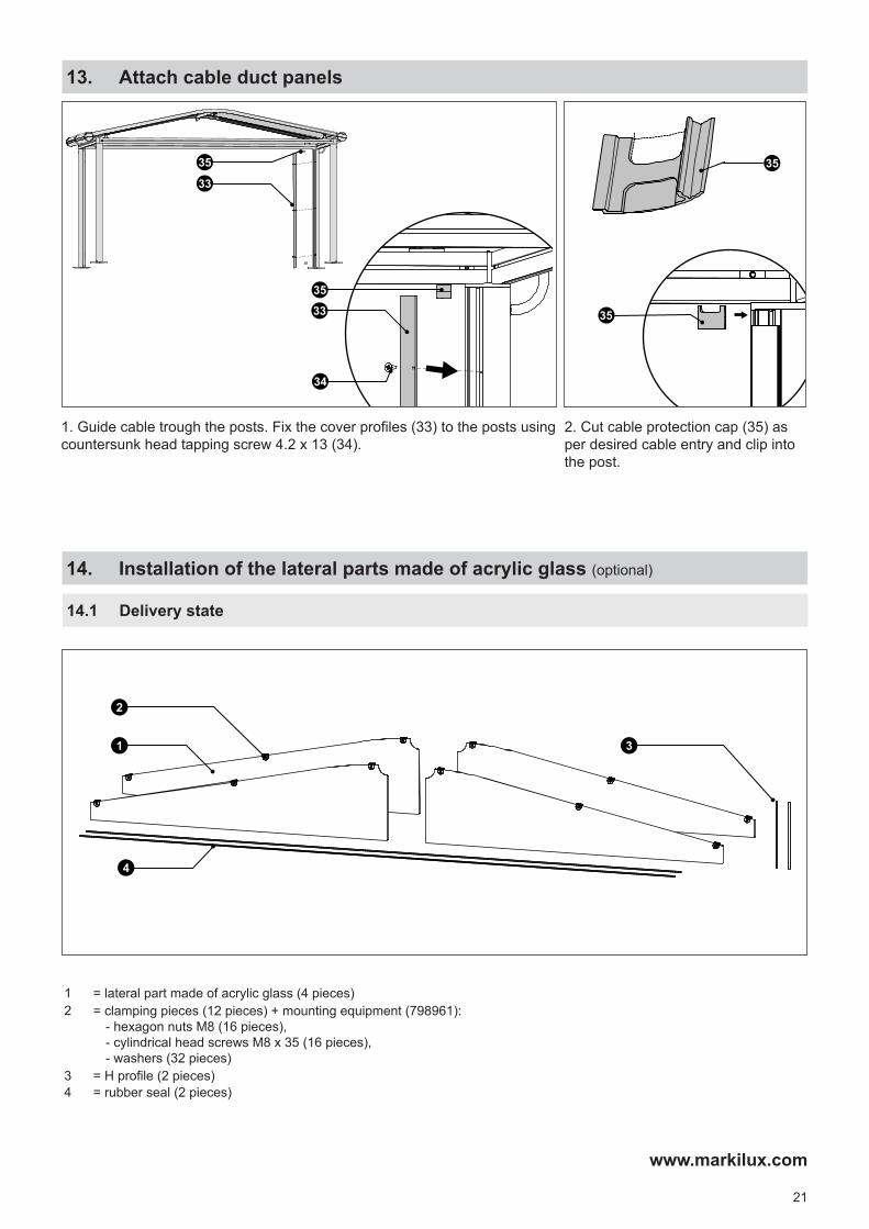
2. Cut cable protection cap (35) as per desired cable entry and clip into the post.
35
35
1. Guide cable trough the posts. Fix the cover profiles (33) to the posts using countersunk head tapping screw 4.2 x 13 (34).
33
35
34
35
33
14. Installation of the lateral parts made of acrylic glass (optional)
18
165
SAMa
14
13
5/6117
16
18
14.1 Delivery state
1
2
3
4
1 = lateral part made of acrylic glass (4 pieces)2 = clamping pieces (12 pieces) + mounting equipment (798961):
- hexagon nuts M8 (16 pieces),- cylindrical head screws M8 x 35 (16 pieces),- washers (32 pieces)
3 = H profile (2 pieces)4 = rubber seal (2 pieces)

22
www.markilux.com
1. Remove about 5 cm of the protective film (5) from the acrylic glass panes at the edge of the drillings and fold over.
Preassembly on the ground: mount the clamping pieces (2) using a cylindrical head screw M 8 x 35 (6) , the hexagon nut M 8 (7) and a washer 9 x 28 x 3 (8) per pane side.
57
2
86
2. Place one half of the preassembled acrylic glass pane (1) into the groove of the cross beam (9).
9
1
3 1
9
4. Put H profile (3) on the edge of the acrylic glass pane (1) that points towards the middle and insert into the groove (9) of the cross beam at the bottom.
102 6
3. Clip the clamping pieces (2) in the groove at the bottom of the guide track (10). Slightly tighten the cylindrical head screws M 8 x 35 (6) of the brackets.
NOTE! The following installation steps apply for the left and right side respectively!

23
www.markilux.com
A
A
A - A
9
1
1
4
9
7. Press the complete acrylic glass pane (1) into the upper groove of the cross beam (9) in the direction of the centre of the awning and insert the rubber seal (4) from the outside into the groove along the entire length of the acrylic glass pane.
5
8. Remove protective film (5) from all acrylic glass panes.
5. Place the second half of the preassembled acrylic glass pane (step 1) into the groove of the cross beam (9) and connect with the first acrylic glass pane in the centre using the H profile (3). While doing this, insert the clamping pieces (2) in the groove at the bottom of the guide track (10) and tighten slightly.
2
10
39
6. Centre the pair of acrylic glass panes between the track brackets (11) and fix the clamping pieces (2) (see step 3).
Attention!Ensure free swivel range of the deflection tube!
11 11
2

24
www.markilux.com
The electrical connection for the motor drive and/or control system connection is to be carried out according to the instructions of the manufacturer of the motor and control system. Modifications, especially concerning the motor, the control system and the connecting supply lines require authorisation in writing.
The installation and setting-up instructions are attached to the motor's power supply cable. Instructions for further electric components are inside the belonging package.
15. Awning with motor drive
15.1 Motor connection
Cable exit point in the case of motor-driven units
dimensions in mm
180
8
130 58 26
The rolling up of the fabric on the fabric roller from below during retraction could lead to damage to the awning. Should you need to change the end stops, it is indispensable to pay attention to the sense of rotation!
The inbuilt motor has an end stop both in extension and retraction direction. The end positions must always be checked on site. Any resetting, changes or corrections must be carried out in accordance with the instructions of the motor manufacturer.
Attention!
Radio-controlled operation (433 MHz) U = 230 V~ / 290 W, 50 Hz, I = 1.25 A
15.2 Motor connection data
Direction of rotation during retraction
Attention!

25
www.markilux.com
16. Individual units next to each other with cover rain gutter (optional)
17. Mounting of cover rain gutter (optional)
11
SAMb
10
9
3. Lift the cross beam (9) and place a support (10) (e.g. piece of wood) underneath. Insert the cover guide track (11) into the groove of the cross beam.
7
SAMb
98
2. Unscrew the lower cylindrical head screw M 10 x 40 (7) at the cross beam recess of the posts. Loosen the upper cylindrical head screws M 10 x 40 (8) so that the cross beam (9) can be lifted.
1. Remove corner caps (5) by loosening the oval-head screws M 5 x 12 (6).
5
6
SAMb
SAMa
2
3
1
4
600
1. The distance between the units (fixture width of the posts) is 600 mm.
1 = markilux pavilion (according to the principle of the conservatory awning 8800 tracfix)2 = frame system markilux RS-1 (optional)3 = acrylic side blind (optional)4 = cover rain gutter (optional)
NOTE!: If the cover rain gutter has to be installed after the unit has been set up completely, you first have to remove the water spout on one side. See chapter 11, step 3 and 4.
Attention! Pay attention to concrete foundations, see chapter 1.2.
SAMa = post separation, centre to centre in extension directionSAMb = post separation, centre to centre in width direction

26
www.markilux.com
4
5. Insert cover rain gutter (4) in the cover guide track (11) simultaneously at both cross beams (9), and wind up uniformly.
NOTE! The unwinding and thus the winding up of the cover onto the unit is effected in the opposite direction to the water spout side. See also step 6!
11
4
4
99
6. Attention!The cover rain gutter has a greater inclination on one side which permits drainage of the water!
12
1/2
9
4. Securely screw the cross beam (9) at the recess of the posts (1 / 2) using cylindrical head screws M 10 x 40 (7).
Repeat steps 3 - 4 on the opposite side of the cross beam recess.
7. Finally fix the corner caps (5) using oval-head screws M 5 x 12 (6).
5
6
1/2

markilux handover declarationfor the users of markilux pavillon
markilux
markilux awnings for outdoor use correspond to standard DIN EN 13561. The wind resistance class for the complete markilux pavillon system is described in the field to the right. The wind resistance class the installation conforms to, is determined specifically by the type and number of fixture brackets as well as the fixture substrate being fitted to.
The awning may be used only up to the wind resistance class declared by the installation company. This may differ from the wind resistance class 3 specified in the CE conformity mark.
In accordance with its knowledge of local conditions and the type of installation it has carried out, the installing company shall inform the user as to whether the wind resistance class permitted by markilux has been met and shall document the actual wind resistance class met by the installation.
Automatic control mechanisms of the awning are to be adjusted so that they react to the appropriate wind resistance class.
wind resistance class 0 Wind resistance class 1 Wind resistance class 2 Wind resistance class 3
Wind resistance class 0 corresponds either to performance criteria that we were not asked to meet or to those that have not been measured or to a product that does not fulfil the requirements of wind resistance class 1.
The awning may remain extended up to a maximum of Beaufort force 4.
The awning may remain extended up to a maximum of Beaufort force 5.
The awning may remain extended up to a maximum of Beaufort force 6.
definition according to Beaufort:
moderate breezeThe wind moves twigs and smaller branches, lifts dust and loose paper.
Definition acc. to Beaufort:
fresh breeze, fresh windSmall deciduous trees begin to sway, white crests forms on seas
Definition acc. to Beaufort:
strong breezeLarge boughs move, umbrellas are difficult to keep under control, telepho-ne wires "whistle" in the wind
Use only under supervision. The awning must be retracted if there is
any wind.
wind speed
20-27 km/h = 5.5-7.4 m/s
wind speed
28-37 km/h = 7.5-10.4 m/s
wind speed
38-48 km/h = 10.5-13.4 m/s
Date: Signature of fitter:
Signature of user*:
The user was duly informed as the operation of the awning. yes no
Following documents have been handed to the user:• operation manual yes no
• Installation and setting instructions supplied by the motor, switch and control unit manufacturer(s) (if available) yes no
The awning may be used under the following conditions:
Wind: X permissable up to wind resistance class = wind speed
Rain: permissable when the awning is fully extended
not permitted with an angle of inclination below 25% = 14°, measured from the horizontal plane
danger of frost and snow X not permitted
* with your signature you confirm that you have received a copy of the handover declaration!
08-04-2014
markiluxSchmitz-Werke GmbH & Co.KG
Hansestrasse 87D-48282 Emsdetten
DIN EN 13561Blinds and awnings for exterior applications
Wind resistance class 3markilux pavillon