Marine Pipeline Technology
9
204 Reports Structural Engineering International 3/2006 Peer-reviewed by international ex- perts and accepted for publication by SEI Editorial Board Paper received: March 28, 2006 Paper accepted: May 22, 2006 Summary The purpose of the present paper is to review the special technical challenges related to the construction of marine pipelines, briefly describing their design, fabrication and installation. The emphasis is on structural aspects of rigid steel pipelines, thus issues related to flexible pipes, riser design, route selection, pipe sizing, flow assurance and operation are not treated. estimated that by the end of the last century close to 100'000 km of large and intermediate diameter marine pipelines had been installed, with ap- proximately 5000 being added each year. The majority of the pipeline systems are located in the heavily de- veloped regions of the Arabian Gulf, the Mexican Gulf and the North Sea. Although marine pipeline technology must be regarded as a mature field there is a shortage of textbooks on the subject. Interested readers are referred to [1, 2, 3]. Marine Pipeline Glossary Functionally, marine pipelines are des- ignated as: – Flowlines, transporting crude hydro- carbons from wellhead platforms or subsea completions to separation or processing facilities. – Service lines, transporting auxiliary media, such as corrosion inhibitor, lift gas or injection water, in the other direction, often together with umbilicals providing power or signalling. – Export pipelines, transporting the produced oil or gas to shore, or to gathering or storage facilities, where they become import pipelines. The above pipelines will typically be part of a pipeline system, including one or several of the following features (cf Fig. 1): – Riser: vertical or near vertical section joining the pipeline on the seabed to topside facilities on an offshore platform. – Expansion offset: Z, U or L-spool installed on the seabed to accom- modate expansions of the pipeline due to the operating pressure and temperature. – Subsea Isolation Valve (SSIV): diver or remotely operated shutdown valve or valve assembly to protect personnel and environment against Marine Pipeline Technology Mikael W. Braestrup, Senior Eng., M Sc, Ph D, Ramboll, Copenhagen, Denmark Introduction The construction of steel pipelines to transport oil, gas, water and other com- modities accounts for a substantial part of worldwide civil engineering activ- ity, and about 10% of all pipelines are installed offshore. With hydrocarbon prices at a consistent, high level the construction of marine pipeline is ac- celerating, particularly for natural gas, which cannot readily be transported in bulk quantities by any other means. This entails taking pipelaying from relatively sheltered waters to harsher environments, such as arctic seas and water depths exceeding 2000 m. Whereas pipelines for the transpor- tation of liquids over land have been known since antiquity, the installation of marine pipelines is a development pertaining to the twentieth century. As a first example is often cited the PLUTO (Pipe Line Under The Ocean) project, which was a war-time effort to supply fuel across the English Chan- nel to the allied troops during the 1944 Normandy landing by means of a 3” (pipe size designation) flexible pipe- line. In reality, however, small diam- eter oil export lines had long before been installed in the shallow waters of the Caspian Sea, the Caddo Lake in Louisiana, or off the US Gulf Coast, where offshore hydrocarbon explora- tion began a century ago. Separate tallying of offshore pipe- lines did not start until 1968, but it is Design 15 km Onshore pipeline Scraper launcher Subsea Expansion offset (Diagrammatic only) 214 km 15 km Shore approach insulating coupling Landfall block valve (s) valve assembly Pipeline riser Platform riser tie - in Offshore pipelaying Treatment plant Plant insulating coupling Scraper receiver Slug catcher Blow - down Fig. 1: Offshore pipeline system schematic
Transcript of Marine Pipeline Technology

204 Reports Structural Engineering International 3/2006
Peer-reviewed by international ex-perts and accepted for publication by SEI Editorial Board
Paper received: March 28, 2006Paper accepted: May 22, 2006
Summary
The purpose of the present paper is to review the special technical challenges related to the construction of marine pipelines, briefly describing their design, fabrication and installation. The emphasis is on structural aspects of rigid steel pipelines, thus issues related to flexible pipes, riser design, route selection, pipe sizing, flow assurance and operation are not treated.
estimated that by the end of the last century close to 100'000 km of large and intermediate diameter marine pipelines had been installed, with ap-proximately 5000 being added each year. The majority of the pipeline systems are located in the heavily de-veloped regions of the Arabian Gulf, the Mexican Gulf and the North Sea. Although marine pipeline technology must be regarded as a mature field there is a shortage of textbooks on the subject. Interested readers are referred to [1, 2, 3].
Marine Pipeline Glossary
Functionally, marine pipelines are des-ignated as:
– Flowlines, transporting crude hydro-carbons from wellhead platforms or
subsea completions to separation or processing facilities.
– Service lines, transporting auxiliary media, such as corrosion inhibitor, lift gas or injection water, in the other direction, often together with umbilicals providing power or signalling.
– Export pipelines, transporting the produced oil or gas to shore, or to gathering or storage facilities, where they become import pipelines.
The above pipelines will typically be part of a pipeline system, including one or several of the following features (cf Fig. 1):
– Riser: vertical or near vertical section joining the pipeline on the seabed to topside facilities on an offshore platform.
– Expansion offset: Z, U or L-spool installed on the seabed to accom-modate expansions of the pipeline due to the operating pressure and temperature.
– Subsea Isolation Valve (SSIV): diver or remotely operated shutdown valve or valve assembly to protect personnel and environment against
Marine Pipeline TechnologyMikael W. Braestrup, Senior Eng., M Sc, Ph D, Ramboll, Copenhagen, Denmark
Introduction
The construction of steel pipelines to transport oil, gas, water and other com-modities accounts for a substantial part of worldwide civil engineering activ-ity, and about 10% of all pipelines are installed offshore. With hydrocarbon prices at a consistent, high level the construction of marine pipeline is ac-celerating, particularly for natural gas, which cannot readily be transported in bulk quantities by any other means. This entails taking pipelaying from relatively sheltered waters to harsher environments, such as arctic seas and water depths exceeding 2000 m.
Whereas pipelines for the transpor-tation of liquids over land have been known since antiquity, the installation of marine pipelines is a development pertaining to the twentieth century. As a first example is often cited the PLUTO (Pipe Line Under The Ocean) project, which was a war-time effort to supply fuel across the English Chan-nel to the allied troops during the 1944 Normandy landing by means of a 3” (pipe size designation) flexible pipe-line. In reality, however, small diam-eter oil export lines had long before been installed in the shallow waters of the Caspian Sea, the Caddo Lake in Louisiana, or off the US Gulf Coast, where offshore hydrocarbon explora-tion began a century ago.
Separate tallying of offshore pipe-lines did not start until 1968, but it is
Design
15 km Onshorepipeline
Scraperlauncher
Subsea
Expansion offset(Diagrammatic only)
214 km 15 km
Shore approachinsulating coupling
Landfall blockvalve (s)
valve assembly
Pipelineriser
Platformriser tie - in
Offshorepipelaying Treatment plant
Plant insulatingcoupling
Scraperreceiver
SlugcatcherBlow - down
Fig. 1: Offshore pipeline system schematic
x170.indd 204x170.indd 204 7/21/06 5:44:40 AM7/21/06 5:44:40 AM
Structural Engineering International 3/2006 Reports 205
the pipeline inventory in case of an accident on the offshore facility.
– Tee or wye: connection point for subsea tie-in of a branch line.
– Pig launcher/receiver: facility for the dispatch or receipt of devices (scrapers) for internal cleaning or batching (operational pigging) or inspection (intelligent pigging) of the pipeline.
– Landfall: connection across the beach and surf zone between the offshore section and an adjoining onshore pipeline.
Structurally, pipelines can be:
– Rigid, i.e. made from steel tubes, ether seamless or welded, the most common material being carbon steel, although corrosion resistant alloys (CRA) may be used for fl owlines, or;
– Flexible, i.e. made from a polymer tube, strengthened against collapse by an internal carcass and against tension and internal pressure by external armour wires.
Rigid pipelines are normally desig-nated by the outer diameter (OD), whereas for flexible lines the internal diameter (ID) is used. Nominal pipe-line diameters are traditionally given in inches, and it is customary to use the terms:
Small diameter: less than 4” Intermediate diameter: from 4” to
16” Large diameter: more than 16”.
The corresponding outer diameter in mm is standardised by the American Petroleum Institute (API), and may be slightly different from the nominal size.
In terms of scope, marine pipelines may be divided into:
– Interfi eld pipelines, connecting off-shore installations within a limited area, and;
– Transmission pipelines or trunklines, transporting large quantities of oil or gas from an offshore complex to shore, or between two landmasses.
Marine pipelines may be required for transmission line crossings of straits, fiords, estuaries or large bodies of water. Recent major projects include:
– Greenstream: 516 km from Italy (Gela) across the Mediterranean to Libya (Mellitah), completed in 2004.
– Langeled: 1166 km from Norway (Nyhamna) across the North Sea to
the UK (Easington), currently under construction.
– North European Gas Pipeline (NEGP): Approximately 1200 km from Russia (Vyborg) across the length of the Baltic Sea to Germany (Greifswald), in the planning stage.
A few decades ago the cost of install-ing a pipeline offshore was an order of magnitude higher than onshore, but ad-vances in marine pipeline technology, coupled with increased costs of land ac-quisition and permits, have reduced the difference to a factor of approximately three. Adding the fact that an offshore route often greatly reduces the number of time consuming and politically sensi-tive authorities’ approvals makes a ma-rine pipeline an interesting option also in cases that are less than obvious, such as the NEGP mentioned above.
Marine Pipeline Design
Design Codes and Safety Formats
Widely recognized pipeline design codes include the following:
– ASME B31-8 Chapter VIII (The American Society of Mechanical Engineers)
– BS 8010 Part 3 (British Standards)– ISO 13623 (International Organi-
zation for Standardization)– DNV OS-F101 (Det Norske
Veritas)
A slightly amended ISO 13623 has been adopted by CEN (European standards writing body) as EN 14161, implying the withdrawal of BS 8010, as British Standards Institution is a member of CEN. However, the Brit-ish national foreword to EN 14161 will advise that a more comprehensive ap-proach to pipeline design is achieved by using the standard in association with PD (Published Document) 8010, which is an updated version of BS 8010.
The DNV OS-F101 [4], although is-sued by a private Norwegian certifying agency is used worldwide. Unlike the other codes, which use an allowable stress design format, the DNV Off-shore Standard adopts the Load and Resistance Factor Design (LRFD) ap-proach.
Under the LRFD format the following different limit states are traditionally considered:
– Serviceability Limit States (SLS)– Ultimate Limit States (ULS)– Accidental Limit States (ALS).
To ensure the required safety against the defined limit states it is custom-ary to use the partial safety coefficient method, which requires that a number of partial safety coefficients be defined for both actions and resistance param-eters. Ideally, the coefficient system should be calibrated to give a uniform safety against all possible failure sce-narios, expressed by a target safety level (reliability index β). In most cases, how-ever, the adopted values reflect accept-ed practice and national priorities. The required safety level (pipeline safety class) will normally depend upon the consequences of pipeline rupture, and the route is divided into zones with dif-ferent safety classes.
The design of the pipeline is closely related to the operational risk analy-sis, which shall document an accept-able risk level with respect to hazards (such as earthquakes or deep penetra-tion anchors) that are so severe and infrequent that it does not make eco-nomic sense to design against them. Scenarios with a high frequency of occurrence (e.g. trawl gear impact) shall be considered in the ALS design. In modern practice, however, these cases, sometimes referred to as Accidental Load Situations, are included under the ULS. Repeated loading may also be considered as a ULS case, although some guidance documents [4] identify a special Fatigue Limit State (FLS).
Wall Thickness Determination
The steel wall thickness of a pipeline is principally determined by the follow-ing considerations:
– Internal pressure containment– Pipe handling and installation – Internal corrosion resistance– External pressure resistance.
The wall thickness for internal pres-sure containment is obtained from the hoop stress formula, which in the sim-plest form reads:
fy > p D/2t,
wherefy: Design yield stress p: Design pressure D: Pipe diametert: Wall thickness.
A more detailed verification takes ac-count of the wall thickness fabrication tolerance and the design strength de-pendence upon temperature and safe-ty class. The following calculations for pressure containment are thus indica-tive only.
x170.indd 205x170.indd 205 7/21/06 5:44:42 AM7/21/06 5:44:42 AM

206 Reports Structural Engineering International 3/2006
Assuming steel with a specified mini-mum yield stress of 450 MPa (API X65) and adopting the partial safety factor 0,72 (in which case D can be identified with the outer diameter), we find fy = 324 MPa. Thus the diameter to thickness ratio for pressure contain-ment is D/t < 648/p, with p in MPa. Assuming the design pressure to be 100 bar = 10 MPa, we find:
D/t < Approximately 65 for pressure containment (100 bar)
Such pipe would, however, be too thin-walled for safe handling and installa-tion. Generally an upper limit of D/t = 45 is adopted, i.e.:
D/t < 45 for handling and installation (general)
In installation by reeling (cf below), however, the pipe is subjected to se-vere bending and straightening, and to limit the permanent plastic strains more strict limits are placed on the diameter to thickness ratio, approxi-mately resulting in:
D/t < 15–23 for reeling
The various requirements to the wall thickness are summarised in Table 1 as a function of the pipe sizes 8” through 30”, according to the proce-dures [4], for design pressures 100 bar and 200 bar. Reeling is feasible for pipe sizes up to 16” only, and the val-ues are calculated for a reel diameter of 15 m. The results are quite sensitive to the ratio between steel yield stress and ultimate tensile strength, assumed at 0,92, thus less onerous requirements can be obtained by specifying steel with a lower yield-to-tensile ratio.
The outer diameter is the metric equivalents of the US customary di-mension, as specified by the API. It is not always equivalent to the nominal pipe size given in the first column, thus e.g. the pipe designated 8” is really 8 5/8 inches. The listed wall thickness is the lowest value, to one tenth of a mil-limetre, satisfying the requirements. In most cases the wall thickness actually adopted will be the lowest standard wall thickness as per the API 5 L Spec-ification for Line Pipe.
The above requirements to wall thick-ness for pressure containment apply to pipeline sections in normal safety class (Zone 1), ie more than 500 m from manned platforms or other areas of frequent human activity (Zone 2), where the required thickness is 40–50% higher. Moreover, for nominal diameters of 8” and above, a minimum
wall thickness of 12 mm in Zone 2 is specified [4].
For carbon steel pipelines transport-ing anything but dry gas or refined petroleum products it is customary to specify a 3 mm corrosion allowance in addition to the wall thickness required for pressure containment. Note that for pressure containment any corro-sion allowance should be increased by the fabrication tolerance (typically 10%).
For media containing Carbon-di-oxide (sweet corrosion) or Hydrogen sul-phide (sour corrosion) it is necessary to determine the annual corrosion rate, which may be reduced by inhibitor in-jection, and calculate the corrosion al-lowance corresponding to the required lifetime of the pipeline, typically 25 years. It is however not prudent to take account of a corrosion allowance in ex-cess of 10 mm. In such cases corrosion resistant alloy (CRA) should be speci-fied either as solid pipe or, as internal cladding or lining of carbon steel pipe.
Once the total wall thickness has been determined it shall be verified that it is sufficient to prevent the pipe from buckling under bending and external pressure. Three different pressures (in order of decreasing magnitude) must be considered:
– Collapse pressure is the external pressure required to buckle the pipe under external pressure alone,
depending upon the concurrent bending and fabrication ovality of the pipe.
– Initiation pressure is the external pressure required to start a propa-gating buckle from a given buckle, depending upon the size of the initial buckle.
– Propagation pressure is the external pressure required to continue a propagating buckle.
The fact that the propagation pres-sure is less than the initiation pressure means that should a buckle be initiated for whatever reason (including third party damage) propagation buckling will flatten the pipeline until it reaches a water depth where the external pres-sure is below the propagation pressure. For pipelaying at water depths exceed-ing the propagation pressure the instal-lation procedures are specified (or the wall thickness adjusted) such that buckles should not be initiated. As a safeguard against propagation buck-ling in case of mishaps the pipeline is provided with buckle arrestors, i.e. sec-tions of thickwalled pipe designed to stop a propagating buckle.
External Corrosion Prevention and Insulation
External corrosion of a pipeline in sea-water is an electrochemical process. A galvanic element is created where an electric current flows between an an-odic area and a cathodic area, with the
PipeSize (”)
Outer Diameter
(mm)
Pressure Containment Handling (D/t < 45)
Reeling(Reel Diameter
15 m)(100 bar) (200 bar)
t (mm) t (mm) t (mm) D/t t (mm)
8 219,1 3,5 6,9 4,9 23,0 9,6
10 273,1 4,4 8,6 6,1 19,8 13,8
12 323,9 5,2 10,1 7,2 17,3 18,8
14 355,6 5,7 11,1 7,9 16,0 22,3
16 406,4 6,5 12,7 9,1 14,4 28,3
18 457,0 7,3 14,3 10,2 N/A N/A
20 508,0 8,1 15,9 11,3 N/A N/A
22 559,0 8,9 17,5 12,5 N/A N/A
24 610,0 9,7 19,1 13,6 N/A N/A
26 660,0 10,5 20,6 14,7 N/A N/A
28 711,0 11,3 22,2 15,8 N/A N/A
30 762,0 12,1 23,8 17,0 N/A N/A
Table 1: Required steel wall thickness t related to pipe outer diameter D as per DNV OS-F101 [4]
x170.indd 206x170.indd 206 7/21/06 5:44:43 AM7/21/06 5:44:43 AM
Structural Engineering International 3/2006 Reports 207
seawater acting as an electrolyte. Cor-rosion at the anodic area will typically be localised (pitting), and corrosion al-lowance offers little protection against external corrosion. Coating of the steel surface protects against corrosion by creating a physical barrier between the pipe and the electrolyte, prevent-ing oxygen from reaching the steel. Cathodic protection, on the other hand, renders the steel immune to corrosion through a lowering of the electrical po-tential, by imposing a galvanic element where the pipeline is the cathode.
Traditionally, the barrier coating is seen as the primary defence against corro-sion, cathodic protection being a back-up measure against coating damage or breakdown. However, cathodic protec-tion might as well be considered the principal corrosion prevention, coating being introduced to reduce the neces-sary current consumption. The gal-vanic element is formed by connecting the pipeline to sacrificial anodes made from metals that have a lower natural potential (i.e. are less noble) than steel, typically zinc or aluminium. Sacrificial anodes are normally mounted on the pipeline (bracelet anodes), and as the anodes are consumed the protective current returns to the pipeline through the seabed and the seawater, which act as an electrolyte.
The cathodic protection system shall be designed to deliver the necessary protection during the design lifetime of the pipeline. This requires suffi-cient anode mass, as well as sufficient exposed anode surface, both criteria depending upon the coating system. A typical 24” trunkline might have an 80 kg aluminium anode per 100 m.
To ensure the proper flow of the me-dium through the pipeline it may be required to provide the pipe with
thermal insulation, which can conve-niently be combined with the external anti-corrosion coating. For large water depths and/or very high insulation requirements, an external steel pipe is however needed for pressure resis-tance (pipe-in-pipe system), the insu-lation material, typically polyolefin foam, being injected into the annulus. As an alternative or supplement to in-sulation active heating of the pipeline may be an option, e.g. by direct electri-cal current.
Hydrodynamic Stability and Protection
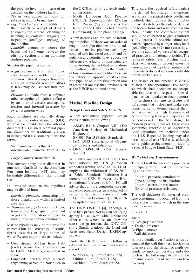
Once the pipeline has been installed on the seabed it shall remain stable under the actions of waves and currents. For a pipeline exposed on the seabed the hydrodynamic forces (lift force FL, drag force FD and inertia force FM), see Fig. 2, depend upon the recurrence interval of the design event, a typical specification being the most dangerous of the 100 year wave combined with the 10 year current or the 10 year wave combined with the 100 year current. A pipeline which is subjected to post-lay trenching is only exposed for a limited period, and if it extends over a winter season it is reasonable to consider the combination of the one year wave with the 10 year current, or vice versa.
The stability design format may be:- static, requiring equilibrium between the hydrodynamic forces and the soil reactions or;- dynamic, allowing move-ments of the pipeline, with restric-tions on total deflections or maximum stresses.
The resisting forces are the submerged weight Ws and the corresponding seabed friction force RH. For safety against flotation a minimum specific gravity (SG) of 1,1 is required, and that
may suffice for deep water pipelines, where the combination of calm water and high wall thickness to resist the hydrostatic pressure obviates the need for added weight. Normally the SG value required for lateral stability is 1,4, increasing to 1,6 or more in coastal areas with high wave action. The most common way of providing negative buoyancy to the pipeline is to apply a concrete coating. The concrete den-sity may be increased by the addition of iron ore aggregate, typically to 3040 kg/m3 (compared to a normal concrete density of 2340 kg/m3), but densities of 3300–3400 kg/m3 can routinely be ob-tained. If it is not feasible to achieve the required negative buoyancy by concrete coating it may be necessary to install the pipeline in a pre-dredged trench to reduce the hydrodynamic forces. In areas with substantial fishing activity, small and intermediate size pipelines must be protected against trawl gear interference (impact, over-trawling and hooking) by lower-ing into the seabed (post-trenching) and/or artificial covering (backfilling or rock dumping). Rock dumping or other seabed intervention may also be needed before or after installation to smoothen the pipeline profile, prevent-ing high contact pressures or excessive free spanning. In particular, free spans shall be investigated with respect to vortex induced vibrations, which might lead to fatigue failure.
When the pipeline is put into opera-tion the increase in internal pressure and temperature will give rise to com-pressive forces in the sections of the pipeline that are restrained by seabed friction. In case of a buried pipeline the axial compression may result in a vertical instability, causing the pipe to break out of the seabed (upheaval buckling), see Fig. 3.
UC UW
FL
WS
RH
DFD,FM
Axial Load
Buckle
Fig. 3: Upheaval buckling of buried pipelineFig. 2: Forces on a marine pipeline subjected to wave and current action
x170.indd 207x170.indd 207 7/21/06 5:44:45 AM7/21/06 5:44:45 AM

208 Reports Structural Engineering International 3/2006
Upheaval buckling is prevented by specifying adequate resistance to ver-tical deformations, provided by the pipe weight and the soil cover. The temperature contribution to the up-heaval buckling force is proportional to the temperature differential (i.e. the difference between the pipeline temperature at operation and at in-stallation) and to the pipe wall thick-ness, and the propensity for buckling is strongly dependent upon the seabed irregularities.
Upheaval buckling analysis is carried out using a linear analysis which cal-culates the equilibrium configuration of the pipeline subjected to internal pressure, elevated temperature and upheaval lifting from a position on a seabed imperfection. The design cri-terion is that the uplift at the apex of the imperfection shall not cause a permanent displacement of the pipe-line through the soil, in which case repeated heating cycles would have a ratchet effect, eventually leading to an upheaval buckle (upheaval creep fail-ure). The result is a set of curves giving the required soil cover as a function of the temperature increase for differ-ent seabed imperfections, which can be used to specify trench depth and smoothness. Should the as-trenched survey disclose sections where this has not been achieved, a non-linear upheaval buckling analysis is carried out taking account of the actual shape of the imperfection, as well as of the pipeline temperature at the topical section. In case that adequate safety against upheaval buckling cannot then be documented, rock dumping must be performed.
Marine Pipeline Fabrication
Linepipe Supply
The principal building block of any marine pipeline is the pipe joint, which is an approximately 12,2 m (40 feet) section of steel tube (called linepipe). Before being assembled into pipe strings and installed on the seabed the individual pipe joints are provided with some or all of the below features, as required by the design:
– Internal coating – External anti-corrosion coating– Thermal insulation– Sacrifi cial anodes– Buckle arrestors– Concrete weight coating.
A typical section in a coated pipe joint is shown in Fig. 4, and Fig. 5 shows a stack of coated pipe joints ready for shipment to the installation contractor. Pipe coating, particularly if concrete is included, is normally applied at a dedi-cated on-shore facility called a coating yard.
The linepipe joints (including any buckle arrestors) are fabricated at ded-icated pipe mills, a typical steel grade being L450 (API X65), with a speci-fied minimum yield stress 450 MPa. Small and intermediate diameter pipe is often seamless, manufactured from a process of piercing and rolling, whereas large diameter pipe tend to be longitudinally welded. A plate strip (skelp) is bent into an open O-shape, and the seam is closed by an automatic welding process. Spiral weld pipe is not
normally used for marine pipelines. The line pipe is delivered to the coat-ing yard, as are sacrificial anodes fab-ricated by specialty suppliers.
Pipe Coating
At the coating yard the pipe joints are cleaned internally and externally by abrasive grit blasting and the substrate is prepared for the subsequent coating by rinsing, phosphoric acid wash and/or chromate conversion treatment. The prepared pipe joints are placed end-to-end on soft rollers, the string moving through the facility.
Internal coating is provided mainly for drag reduction, but also to prevent corrosion during outdoor storage (see Fig. 5). A typical coating is two-com-ponent epoxy paint; spray applied to
73−105 mm Iron ore concrete coating
5 or 6 mm Mild steel bars
8−10 mm Deformed bars
5 mm Coal tar enamel coating
Pipe wall t = 18,7 mm
Fig. 4: Typical cross-section of coated pipe
Fig. 5: Coated pipe joints stacked for shipment
x170.indd 208x170.indd 208 7/21/06 5:44:48 AM7/21/06 5:44:48 AM

Structural Engineering International 3/2006 Reports 209
a dry film thickness of 100 micron. Unless special measures are taken to protect the girth weld areas the coating is not effective against internal corro-sion, and it is therefore primarily used for pipelines transporting dry gas.
For external corrosion protection, hot applied enamel coatings have been the dominant option, and they remain the preferred choice for pipes pro-vided with concrete weight coating. For health, safety and environmental reasons toxic coal tar enamel is in-creasingly being replaced by asphalt (bitumen). After the application of a synthetic primer the 200 ̊ C bitumen mixture is flooded onto the rotating pipe, reinforced by one or two lay-ers of fibreglass inner wrap spirally wound around the pipe, and capped by a bitumen impregnated fibreglass felt outer wrap, see Fig. 6. The total coating thickness is 4–5 mm.
Pipelines without concrete coating, or subjected to operating temperatures exceeding 80 ̊ C, are increasingly pro-vided with a three-layer polyolefin coating, typically comprising a fusion bonded epoxy primer, a copolymer adhesive, and a top layer of poly-ethylene, polypropylene or polyure-thane, depending upon the required mechanical protection and service temperature. The primer is applied by electrostatic, airless spraying of epoxy powder onto the heated pipe, followed by extrusion of the adhesive and top layers, to a total thickness of 2–3 mm. Thermal insulation may be applied in the same operation. A typical sys-tem includes polyurethane foam with a high density polyethylene outer sleeve pipe, which can provide insulat-ing with an overall heat transfer coef-ficient (U-value) as low as 1 W/m2/K. For deep water application external
pressure resistance is achieved by im-bedding hollow spheres in a polymer matrix (syntactic foam).
Joints to be provided with sacrificial anodes are separated before concrete coating. Two cylindrical half-shells are mounted on the pipe, fitted tightly by straps and come-alongs, and subjected to final adjustment, see Fig. 7. Each half-shell is electrically connected to the linepipe steel by thermit welding or pin brazing of copper cables. On pipelines without concrete coating the anodes are normally mounted during the offshore installation.
For some early marine pipelines the concrete weight coating was manufac-tured in the traditional way, by cast-ing in shutters around the pipe, and this method may still be used for site application of concrete coatings of minor stream crossings, etc. For long transmission lines, however, this pro-cedure it is too costly and time con-suming. Methods have been developed which dispense with the formwork, the most common being impingement, a
process whereby a fairly dry (no-slump) concrete mix is thrown at the rotating pipe, see Fig. 8. Depending upon the location of the project it is customary to require the use of low-alkali, sulphate resistant cement, or al-ternatively blast furnace slag cement, which has a good track record for ma-rine applications.
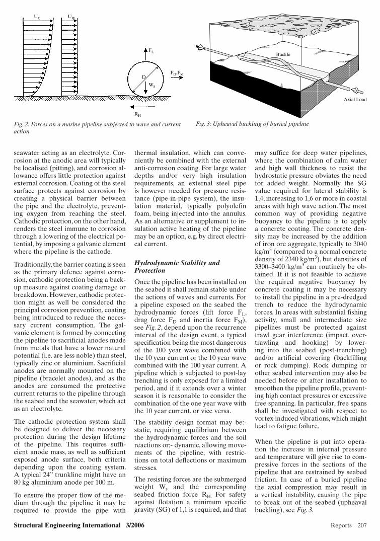
Reinforcing steel is provided, either as welded wire mesh, which is wound around the pipe simultaneously with the concrete application, or in the form of prefabricated cages, which are placed on the pipe joint prior to con-crete application, and held in position by spacers, see Fig. 9. The reinforce-ment ratio shall be sufficient to ensure the integrity of the coating during han-dling, transport, installation and op-eration, including the impact of fishing equipment. Typical specifications are minimum 0,08% in the longitudinal direction, and 0,5% circumferentially. Electrical contact to the pipe steel or to any anodes must be avoided. The anodes are shielded from contami-nation by cement or concrete, and if
Fig. 6: Enamel, inner wrap and outer wrap applied to pipe joint Fig. 7: Mounting of sacrificial anode on enamel coated pipe joint
Fig. 8: Schematic sketch of concrete impingement unit
Scraper for surface levelling
Impinged concrete
Rotating wire brush
Concrete from mixer
Conveyor beltSteel pipe
Fall-of returned to mixer
x170.indd 209x170.indd 209 7/21/06 5:44:54 AM7/21/06 5:44:54 AM
210 Reports Structural Engineering International 3/2006
the concrete thickness is greater than that of the anodes (which is typically 40 mm) the concrete coating is tapered down to the anode.
To leave room for the girth welding equipment at pipe assembly the con-crete coating is stopped at a distance (typically 360 mm) from the pipe ends. By adjusting the travel speed and the rate of rotation of the pipe the opera-tor obtains the desired thickness of the coating, which is smoothened by scrapers. It is particularly important to avoid bulging of the coating at the pipe ends, as this can lead to spalling and radial cracking when the coated pipes are stacked. For the same reason the coating edge is slightly rounded at the ends, which are otherwise finished off square.
For practical reasons the minimum concrete thickness is 40 mm, and up to approximately 150 mm concrete can be applied. In principle greater coating thickness can be obtained by applying a second layer after curing of the first. The productivity of the impingement method is impressive, a well-func-tioning unit being capable of coating 1–1,5 km of pipe per eight hour shift, corresponding to the application of around 40 m3 of concrete per hour.
Marine Pipeline Installation
Survey and Seabed Intervention
The first installation activity is a de-tailed survey of the pipeline route, to complement information gathered during the route selection process. The purpose is twofold:
– Geophysical survey, principally to obtain a bathymetric profi le and identify seabed obstacles, crossing pipelines and cables, etc., typically by means of echosounder and side-scan sonar.
– Geotechnical survey, to obtain infor-mation (classifi cation and strength/deformation parameters) of the seabed soils, typically by means of vibrocoring, cone penetration testing and seabed sampling.
Additional surveys are performed after pipeline installation (As-Laid) and trenching (As-Trenched), as well as to verify backfilling or other protec-tive measures.
The survey results are used to assess the need for seabed intervention, the most common being the reduction of free spans. Spans that are unaccept-able in the unstressed, airfilled condi-tion of the pipeline must be rectified before installation of the pipeline (pre-lay intervention), whereas other free span rectification can wait until after the pipe string has been placed (post-lay intervention). For the fatigue
verification it is common industry practice to require that no more than 10% of the allowable damage ratio be reached during the temporary in-stallation phases, which in addition to the laying, where the pipe is sub-jected to barge motions, include a period in which the pipeline is empty on the seabed and a period in which it is waterfilled. As the free spans are typically larger in the former case the accumulated damage due to vortex induced vibrations can be reduced by flooding the pipeline shortly after in-stallation, thus obviating the need for pre-lay span rectification.
Reduction of free spans can be achieved either by the removal of sea-bed material (peaks or shoulders), or by the establishment of intermediate supports, typically as berms of gravel or rock. The rock dumping may be performed by split barges, but much more economical use of material is obtained by using a rock dumping ves-sel equipped with a fall pipe, through which the material may be placed with great accuracy. Fall pipe dumping is routinely performed at water depths exceeding 300 m, the vertical tolerance being +/– 200 mm. On the Greenstream project, rock dumping in the Mediter-ranean was successfully carried out at a depth of 887 m.
Pipelaying
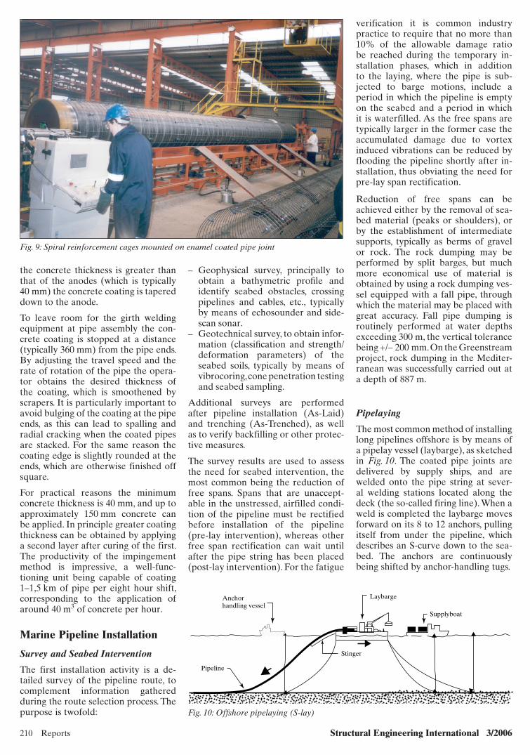
The most common method of installing long pipelines offshore is by means of a pipelay vessel (laybarge), as sketched in Fig. 10. The coated pipe joints are delivered by supply ships, and are welded onto the pipe string at sever-al welding stations located along the deck (the so-called firing line). When a weld is completed the laybarge moves forward on its 8 to 12 anchors, pulling itself from under the pipeline, which describes an S-curve down to the sea-bed. The anchors are continuously being shifted by anchor-handling tugs.
Fig. 9: Spiral reinforcement cages mounted on enamel coated pipe joint
Fig. 10: Offshore pipelaying (S-lay)
Anchorhandling vessel
Pipeline
Stinger
Laybarge
Supplyboat
x170.indd 210x170.indd 210 7/21/06 5:45:02 AM7/21/06 5:45:02 AM

Structural Engineering International 3/2006 Reports 211
The pipeline leaves the laybarge over a stinger, the configuration of which controls the curvature of the hogbend. Buckling of the sagbend at the seabed is prevented by keeping the pipeline under tension, provided by tensioners gripping the pipe string on the layba-rge, see Fig. 11.
A third generation, semi-submersible pipelay vessel working around the clock is capable of installing 3–4 km of pipeline per day, corresponding to the addition of a 12 m pipe joint every five minutes, approximately. To increase the lay speed two pipe joints are often welded together at a separate location (double-jointing) before being added at the firing line.
In deep waters (several hundred me-tres) anchor handling becomes imprac-tical, and some modern laybarges rely on dynamic positioning, being able to keep station by means of powerful thrusters. At very large water depths the S-lay figuration is replaced by J-lay, where the pipe string enters the water in a vertical or nearly vertical position. This eliminates the firing line, which means that welding must take place at one station only. Thus double-jointing (or even triple- or quadruple-jointing) is essential to maintain a reasonable lay rate. A newly commissioned J-lay barge was used in 1999–2000 to install the dual 24” Blue Stream pipelines 240 km across the Black Sea from Rus-sia to Turkey at a record water depth of 2150 m. The performance of S-lay barges has since been improved, and the 32” Greenstream pipeline from Libya to Italy at maximum water depth 1127 m was installed by S-laying.
An alternative method is reeling, whereby pipe strings are welded up at an onshore facility, and spooled onto large reels on special reel barges. The reel holding in the order of 10 km of pipeline is normally vertical, and in-stallation is much like J-lay, except that offshore girth welding is only needed when the next pipe string is added. In case of small diameter pipelines new reels may be delivered by supply boats, otherwise the reel barge must return to the spool base to load a string. In the meantime the pipeline is capped and temporarily abandoned on the seabed.
Girth Welding and Field Joint Preparation
The normal choice for firing line weld-ing is mechanised gas metal arc weld-ing (GMAW) or shielded metal arc welding (SMAW) using cellulosic elec-trodes. A typical semi-automatic field welding is shown in Fig. 12. Double joint welding is usually fully automatic submerged arc welding (SAW).
The firing line welds are inspected and tested before leaving the barge. If non-acceptable defects are detected the line is pulled back and the weld is repaired by either a complete cut out or an ap-proved local weld repair procedure.
After welding of the linepipe steel the weld area and the adjacent coating cut-back is protected by field joint coat-ing. Corrosion protection is normally achieved with tape wrapping or heat shrink sleeves, and if both the adjacent pipe joints are provided with concrete coating or insulating coating a suitable infill material is applied to the field
joint area, to create a continuous pipe string.
Trenching and Pre-commissioning
Permanent installation of the pipe-line below the natural seabed is called trenching, the main objectives being:
– To protect the pipeline from hydro-dynamic forces.
– To protect the pipeline against mech anical damage.
– To eliminate or reduce free spans.– To prevent upheaval buckling.– To increase thermal insulation of the
pipeline.
In some cases the pipeline may be placed in a pre-dredged trench, but in most cases post-trenching is used to lower the pipeline into the seabed. Post-trenching methods include:
– Water-jetting – Mechanical cutting – Ploughing.
Water-jetting is performed by means of a jet sled, which is riding on the pipeline, guided by rollers at the top and the sides of the pipe. The jet sled is pulled by a trench barge, which also delivers the compressed water that is ejected trough nozzles at each side of the pipeline. The water jets liquefy and displace the seabed soil, leaving a trench into which the pipeline sinks. Several passes of the jet sled may be necessary to achieve the specified dis-tance from the natural seabed to the top of the pipe.
In cohesive soils with shear strengths exceeding approximately 100 kPa the water nozzles are replaced by cutting
Fig. 11: Tensioner holding pipeline on S-lay barge Fig. 12: Field joint welding on laybarge
x170.indd 211x170.indd 211 7/21/06 5:45:06 AM7/21/06 5:45:06 AM

212 Reports Structural Engineering International 3/2006
heads, which excavate a V-shaped ditch in the seabed. Whether jetting or cut-ting, the trenching vehicle may also be self-propelled on tracks or skids, and remotely operated, power and control being delivered by an umbilical from a surface vessel. In deep waters only remotely operated trenching systems are used.
The trench may also be excavated by a plough, which is clamped around the pipeline in such a way that the shears displace the soil from under the pipe-line, depositing it in walls alongside the trench. The plough is supported on skid beams, being guided along the pipeline by rollers, and is pulled by a surface vessel, see Fig. 13. If immedi-ate soil cover is required, eg to protect against dragging anchors or to prevent upheaval buckling, a second passage of the plough may scoop the exca-vated material back into the trench, or rock dumping must be performed. Over the longer term natural backfill-ing will often take place, and on sandy seabeds natural self-lowering of the pipeline may occur, obviating the need for trenching to ensure stability.
Pre-commissioning includes the fol-lowing activities:
– Flooding and hydrostatic testing– Cleaning and gauging– De-watering and drying.
The pipeline is filled with water (nor-mally seawater, possibly with chemi-cals preventing internal corrosion),
and subjected to the acceptance pres-sure test, which is normally part of the scope for the installation contractor. Flooding may take place immediately after – or even during – installation to ensure hydrodynamic stability, reduce free spans and/or facilitate trenching.
The activities of de-watering and dry-ing are particularly important for gas pipelines, because any remaining water may react with the gas to form hydro-carbon hydrates, which can obstruct the flow and in particular the proper functioning of valves.
Cost and Schedule
A ballpark figure for the cost of a marine pipeline is one million EUR per km. Obviously larger diameter pipelines are more expensive per ad-ditional kilometre, but they also tend to be longer, and thus less affected by mobilisation and tie-in costs. The most important cost items are linepipe steel and pipelaying, each typically account-ing for one third of the total cost.
Recent years’ increasing steel prices have abated somewhat, and carbon steel linepipe would be in the price range of EUR 1000–2000 per ton, de-pending upon the size of the order. Corrosion resistant alloys are an order of magnitude more expensive. The only other material supply that match-es linepipe in economic impact is insu-lation, which can add several hundred
Fig. 13: Trenching plough being deployed from trench vessel
thousand Euros per km to the price tag. The cost of a pipelay spread is ap-proximately EUR 400'000 per day, and the day rate of a diving support vessel, used for pipeline crossings, tie-in op-erations, etc., is in the order of EUR 200'000.
Also project schedule concerns are dominated by linepipe supply and pi-pelaying. The number of qualified pipe mills is limited, and for a major order lead times exceeding 12 months should be envisaged. The pipeline installation market is even more overheated, and a contract will have to be negotiated several years in advance. As a result several new pipelay vessels are being commissioned, and together with up-grading of existing barges this is likely to bring relief in the not so distant future.
An item not to be forgotten is authori-ties’ approval, as several operators have learned the hard way. A marine pipeline entirely in a single national sea territory may be processed in six months, or even less, but a major proj-ect, requiring the preparation of en-vironmental impact assessments, can take years, particularly if landfalls are included.
Conclusion
The installation of pipelines in the ocean is a mature, yet rapidly evolving, field of technology. A large number of projects are on the drawing board to satisfy the world’s appetite for en-ergy supply, and the resulting technical challenges call for the participation of bright and innovative engineers.
References
[1] YONG BAI. Pipelines and Risers, Elsevier Ocean Engineering Book Series, Volume 3, 2001, pp. 498.
[2] PALMER, A. C; and KING, R. A. Subsea Pipeline Engineering, PennWell, 2004, pp. 570.
[3] BRAESTRUP, M. W; ANDERSEN, J. B; ANDERSEN, L. W; BRYNDYM, M. B; CHRIS-TENSEN, C. J.; and RISHØJ, N. Design and Installation of Marine Pipelines, Blackwell Pub-lishing, Oxford, 2005, pp. 342.
[4] Det Norske Veritas: Submarine Pipeline Sys-tems DNV Offshore Standard OS-F101, 2000, pp. 203.
x170.indd 212x170.indd 212 7/21/06 5:45:18 AM7/21/06 5:45:18 AM