Marine Engineering System
114
Marine Engineering System
Transcript of Marine Engineering System

Marine Engineering System

Introduction

Life and Measurement

Administration
Course content Class Class notes Assessment -Homework assignments and solutions Final Exam Labs Others : Collaborative work, attitude,
communication, learning through variation and creativity and new ideas.

Variation
• We only learn because of variation – when something new or different challenges our pre-conceived ideas
• What we learn depends on the variation we have experienced

Subject General Objective Introduction to shipping ships and general Introduction to shipping ships and general
marine engineering systemsmarine engineering systemsCoverage:
Common marine engineering termsCommon marine engineering terms Safe working practice onboard ships Safe working practice onboard ships Type of Merchant shipsType of Merchant ships Type of Naval ships Type of Naval ships Type of auxiliary craftsType of auxiliary crafts Shipboard systemsShipboard systems Engine room and Machinery layoutEngine room and Machinery layout

Course Navigation
- Marine engineering terms and system
- Operating principle, characteristics and classification of marine engines and supporting systems
- Principle of operation ships auxiliary machineries system
- Marine electrical power generation and distribution system
- Marine propulsion system
This lecture – Introduction to marine engineering and ship systemAt the end of the lesson student will be
able to : Define common terms of ship and
marine engineering system Ship types Marine engineering system Propulsion layout Hull Safety consideration Design consideration

A. Marine engineering and marine engine

Evolution of marine engine
Effort to apply mechanical power to propulsion and operation of ship since eighteen century as never been easy.
Why?

Design requirement
Because ship is a have never been a simple product
It require exceptional number of specialization to plan ,design and build a ship
This make maritime technology distinctive integrated technology in part of many engineering disciplines require for the design of system of transport, exploration, naval craft which have one thing in common. What ?

Design requirement
Operate on the surface of water The field of engineering under maritime technology
– naval architecture and marine engineering is with at least the following:
Inland waterway and ocean transportation Naval engineering Ocean engineering Contention between naval architecture and marine
engineer in system design

1. Common terms

Common terms Ships Vessels Submarines Tugs Ferries Boats Class societies & Mardep Propulsion system

Common terms (Contd)
Auxiliary Power system Air system SW system FW system Fuel system Hospitality systems Navigation and steering system

2. Safe working practice

Safe working practice Special constraints of ship operation
Ship is a floating and moving object Subject to flooding, rolling & Pitching Limited space for machinery Operates away from shore facilities No neutral line to earth
Carries heavy and dangerous cargo

How to enforce Safety
Proper safety attire Regular and effective maintenance
Repairs / drydocking/inspection Load Testing of lifting equipment Test of Firefighting system
Periodic certification and validation of ships and its systems

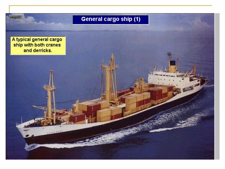
3. Ship Types
&
Hull Forms

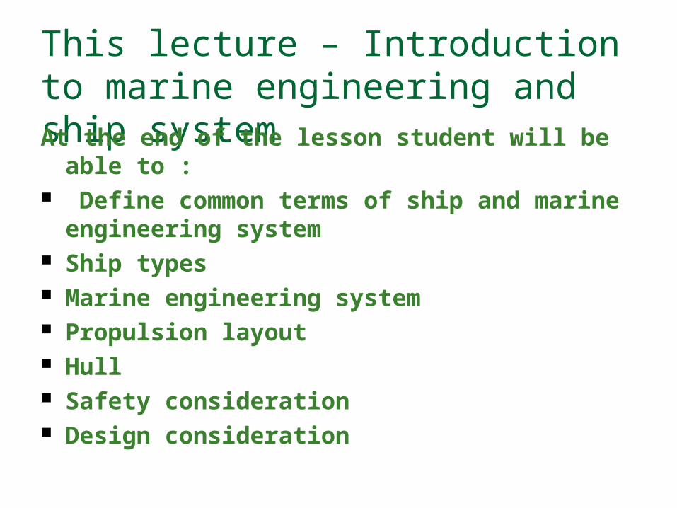
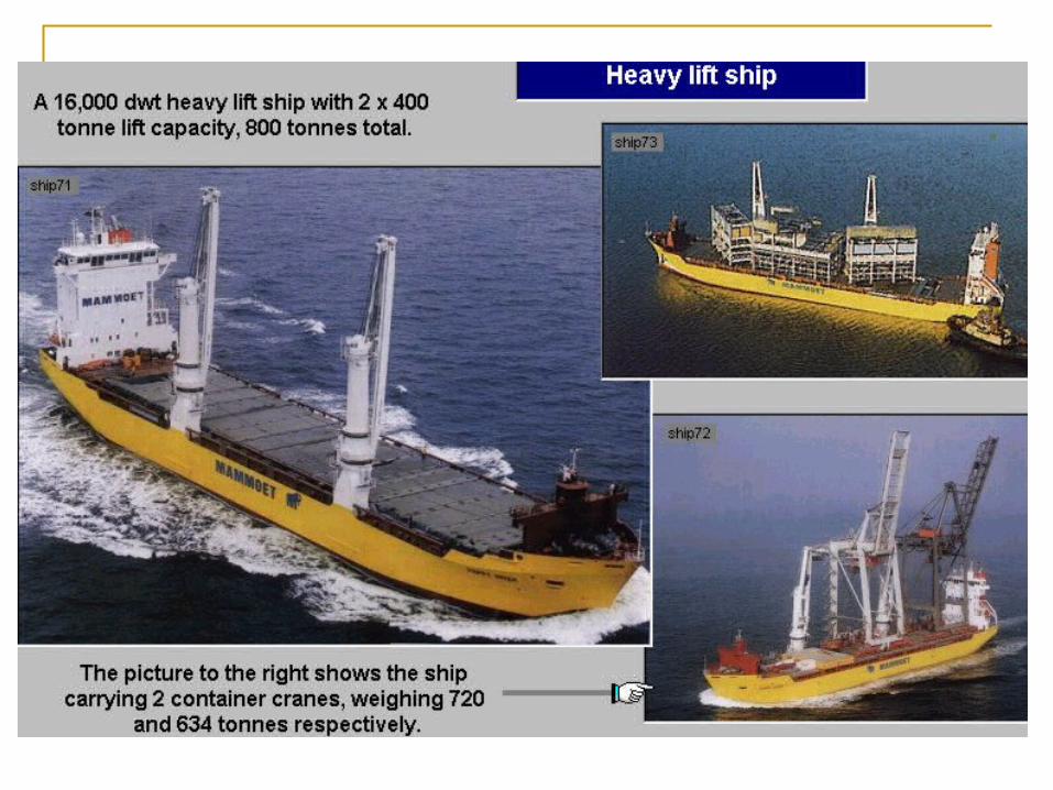
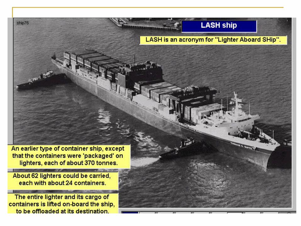
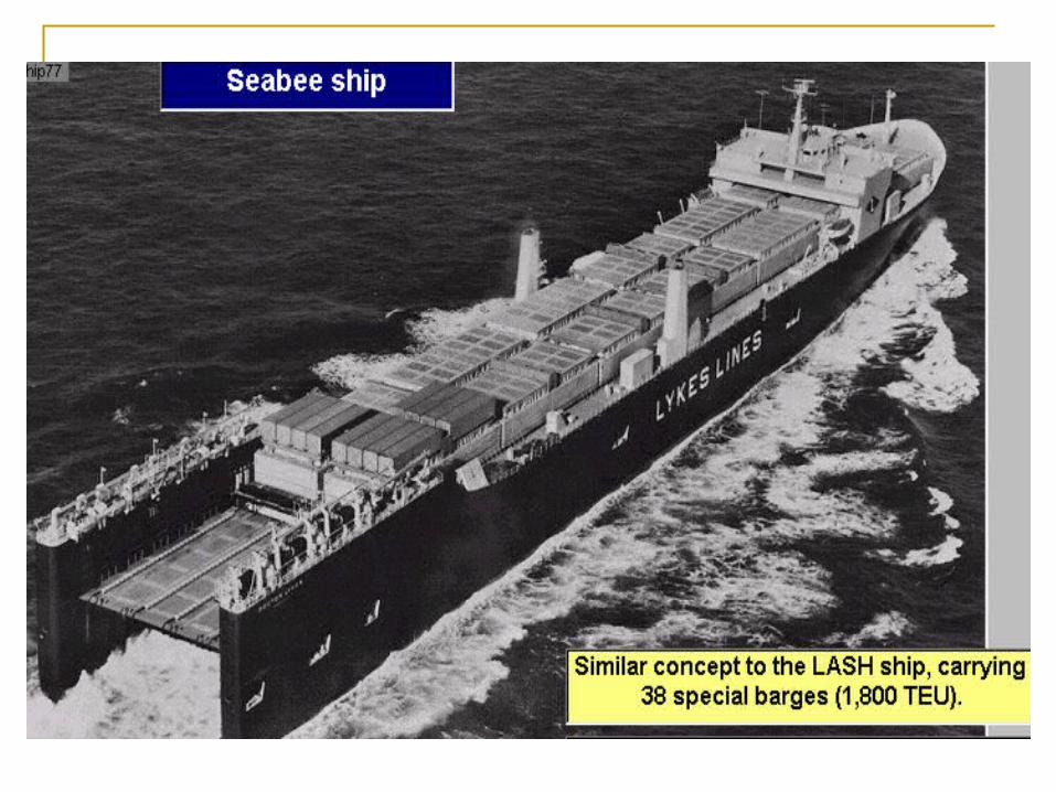
Types of Ships Merchant ships
Bulk carriers Oil Tankers Chemical tankers LNG tankers Container ships Passenger liners
Naval Ships Frigates Destroyers Cruisers Aircraft carriers Patrol crafts Survey ships Submaries
Auxiliary Vessels Tugs Ferries Support vessels Barges

3.1 Classification of Ship by Usage Merchant Ship
Naval & Coast Guard Vessel
Recreational Vessel
Utility Tugs
Research & Environmental Ship
Ferries


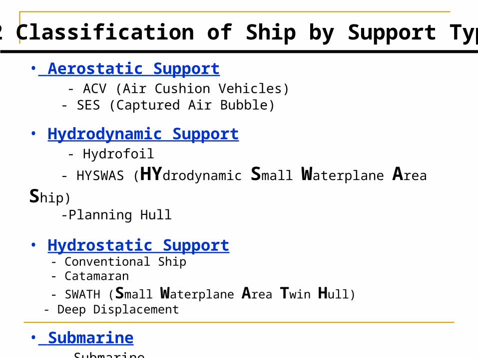
3.2 Classification of Ship by Support Type
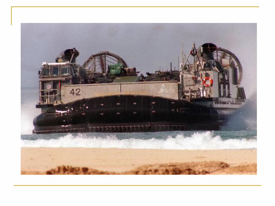
• Aerostatic Support - ACV (Air Cushion Vehicles) - SES (Captured Air Bubble)
• Hydrodynamic Support - Hydrofoil
- HYSWAS (HYdrodynamic Small Waterplane Area Ship) -Planning Hull
• Hydrostatic Support - Conventional Ship - Catamaran
- SWATH (Small Waterplane Area Twin Hull) - Deep Displacement
• Submarine - Submarine - AUV/ROV

3.3.1 Aerostatic Support
- Supported by cushion of air generated by a fan. - ACV (Air Cushion Vehicle)
hull material : rubber propeller : placed on the deck amphibious operation - SES (Surface Effect Ship)
side hull : rigid wall(steel or FRP) bow : skirt propulsion system : placed under the water water jet propulsion supercavitating propeller not amphibious operation

E
SES Ferry
NYC SES Fireboat

250’ SES Ferry

• Planning HullPlanning Hull - supported by the hydrodynamic pressure developed - supported by the hydrodynamic pressure developed under the hull at high speedunder the hull at high speed - V or flat type shape- V or flat type shape - commonly used in pleasure boat, patrol boat,- commonly used in pleasure boat, patrol boat, missile boat, racing boat missile boat, racing boat
3.3.2 Hydrodynamic Support
Destriero


• Hydrofoil ShipHydrofoil Ship - - supported by a hydrofoil, like wing on an aircraftsupported by a hydrofoil, like wing on an aircraft - fully submerged hydrofoil ship- fully submerged hydrofoil ship - surface piercing hydrofoil ship- surface piercing hydrofoil ship
3.3.3 Hydrodynamic Support
Hydrofoil Ferry
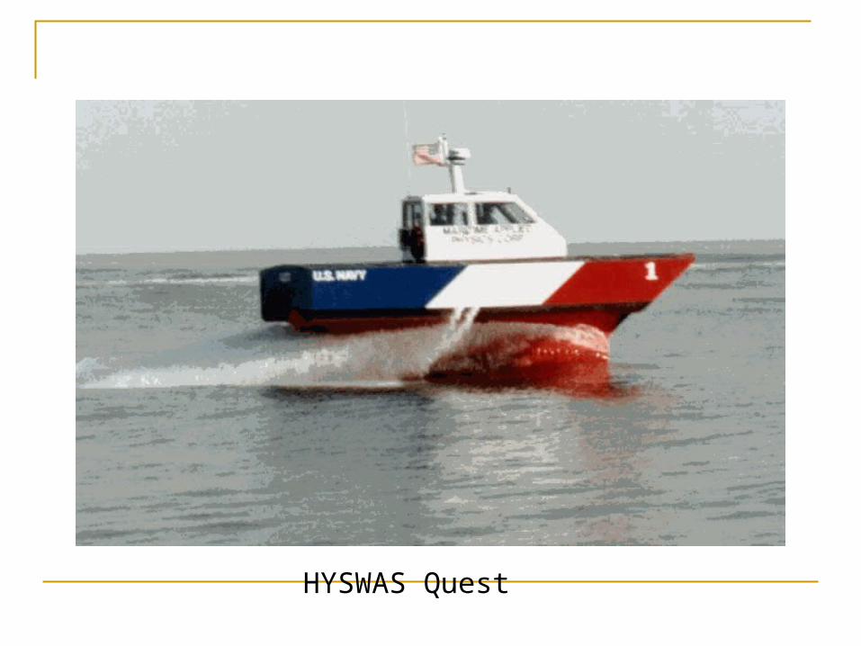
HYSWAS Quest

Hydroplane vessel


3.3.4 Hydrostatic Support
• Displacement ship - conventional type of ship - carries high payload - low speed • SWATH - small waterplane area twin hull (SWATH) - low wave-making resistance - excellent roll stability - large open deck - disadvantage : deep draft and cost• Catamaran/Trimaran - twin hull - other characteristics are similar to the SWATH• Submarine


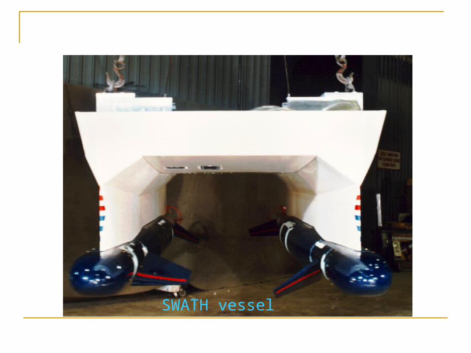
SWATH vessel


SWATH vessel Seashadow


Tri-Hull combat concept vessel


4. Shipboard systems

Shipboard systems Propulsion system
Steam Diesel Gas turbine All electric CODAD CODAG COSAG
Aux power system AC/DC LV HV

contd Sea Water system Fire fighting system Pumping and flooding system FW system Aircon and ventilation system FW system Cargo system Navigation system and steering
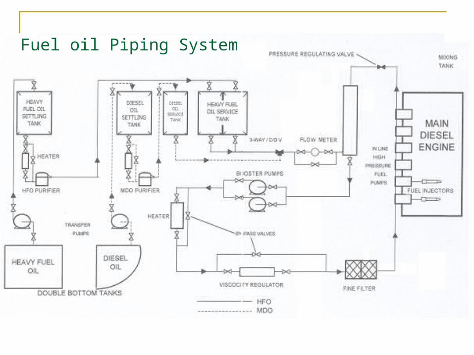
Fuel oil Piping System

EXPANSION / HEADER TANK
TURBOCHARGER S/W OUT
TO & FROM
DIESEL GENERATOR
J ACKET
WATER
COOLER
J KT. WATER COOLING P /P S
CYLINDER BLOCK S/W IN
& CYLINDER HEAD
DISTRIBUTION MANIFOLD
S/W OUT
P ISTONS
DISTRIBUTION MANIFOLD P ITON
WATER
P ISTON WATER COOLING P /P S COOLER
COLLECTION MANIFOLD S/W IN
FROM P ISTON
FRESH WATER SYSTEM
MAIN DIESEL ENGINE
P ISTON DRAIN TANK
HEATER
Fresh Water Cooling System
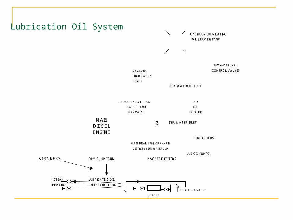
CYLINDER LUBRICATING
OIL SERVICE TANK
CYLINDER
LUBRICATION
BOXES
SEA WATER OUTLET
CROSSHEAD & P ISTON LUB
DISTRIBUTION OIL
MANIFOLD COOLER
SEA WATER INLET
FINE FILTERS
MAIN BEARING & CRANKP IN
DISTRIBUTION MANIFOLD
LUB OIL PUMPS
STRAINERS MAGNETIC FILTERS
STEAM
HEATING
LUB OIL PURIFIER
HEATER
COLLECTING TANK
DRY SUMP TANK
LUBRICATING OIL
CONTROL VALVE
TEMPERATURE
LUBRICATION OIL SYSTEM
MAIN DIESEL ENGINE
Lubrication Oil System
TURBOCHARGER
J ACKET
FRESH
WATER
COOLER
CHARGE
AIR COOLER
PISTON LUB OIL
WATER COOLER
COOLER
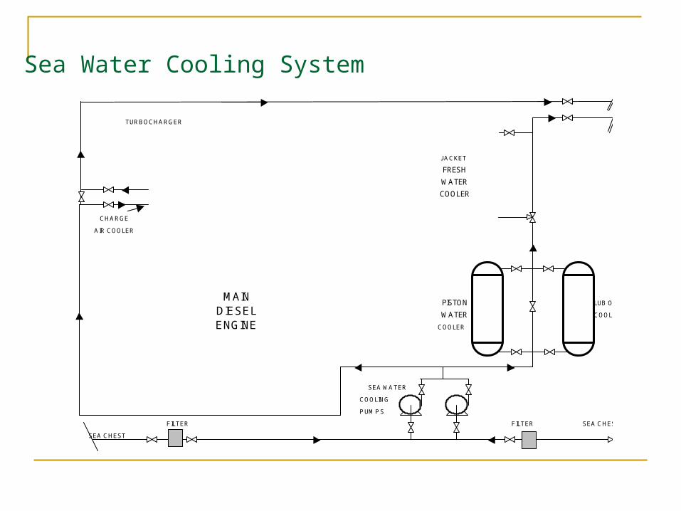
SEA WATER
COOLING
P UMP S
FILTER FILTER SEA CHEST
SEA CHEST
SEA WATER COOLING SYSTEM
MAIN DIESEL ENGINE
Sea Water Cooling System

STARTING AIR VALVES
P ILOT
VALVE
AIR BOTTLE
OR
RESERVOIR
AIR DISTRIBUTOR
MAIN AIR
COMP RESSORS
STARTING AIR SYSTEM
MAIN DIESEL ENGINE
No 1 No 2
No 2No 1
Air Starting System

Main Diesel Engine Cooling System

5. Types Marine Engine
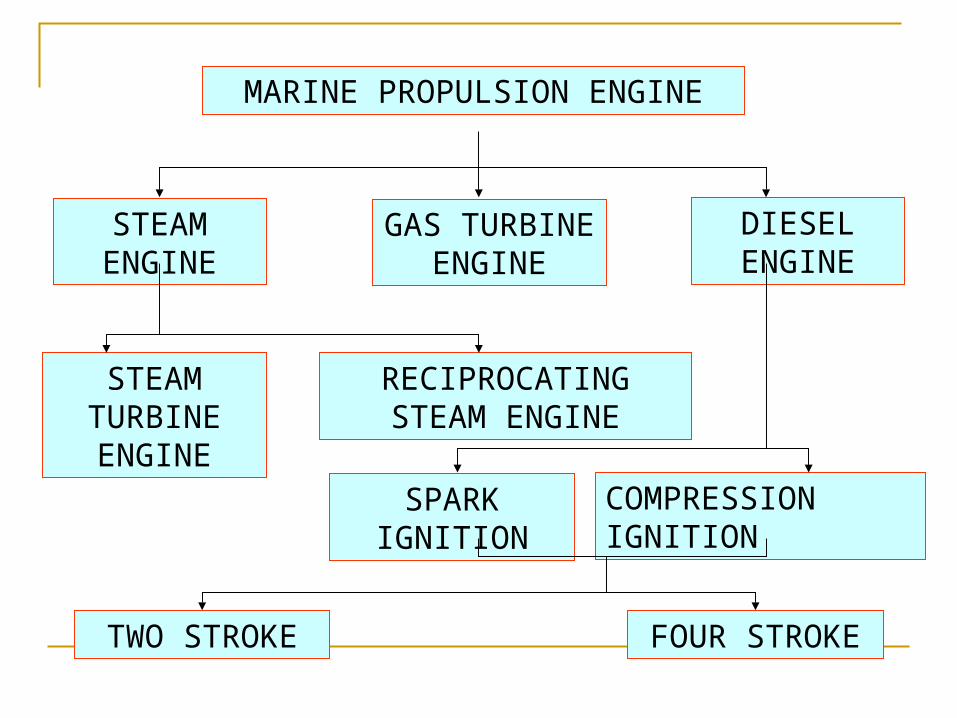
MARINE PROPULSION ENGINE
STEAM ENGINE
DIESEL ENGINE
GAS TURBINE ENGINE
STEAM TURBINE ENGINE
RECIPROCATING STEAM ENGINE
SPARK IGNITION
COMPRESSION IGNITION
TWO STROKE FOUR STROKE

CATERGORIES
Steam Turbine Engine
Gas turbine engine
Steam Engine
Diesel engine

Prime moversGas Turbines Gas turbine have been selected as the future prime mover primarily
because of their high power to weight ratio. 4. Weight sensitive ship designs favor gas turbines and projected light
weight fuel cell power plants such as PEM. They also provide significant reduction in the amount of routine
maintenance required when compared with diesel generators. The other significant factor is the low emissions.
Diesel engine Diesel engines offer fuel costs savings of 50% if heavy fuels can be
used, and if emissions can be maintained at acceptable levels. Maintenance may include engine modifications such as dual fuel
capability for in-port use, water injection, and timing retard, and exhaust treatment such as selected catalytic reduction and oxidation catalysts.
Heavy fuel use also requires careful selection of cylinder material and lube oil
Turbine A gas turbine, also called a combustion turbine, is a rotary engine
that extracts energy from a flow of hot gas produced by combustion of gas or fuel oil in a stream of compressed air.
It has an upstream air compressor radial or axial flow mechanically coupled to a downstream turbine and a combustion chamber in between.
Energy is released when compressed air is mixed with fuel and ignited in the combustor
The resulting gases are directed over the turbine's blades, spinning the turbine, and, mechanically, powering the compressor.
Finally, the gases are passed through a nozzle , generating additional thrust by accelerating the hot exhaust gases by expansion back to atmospheric pressure.
A steam turbine is a mechanical device that extracts thermal energy from pressurized steam , and converts it into useful mechanical work.
Steam Turbine engine
The Steam turbine is use to obtain mechanical work from the energy stored in steam.
Steam enters the turbine with high energy content and leaves after giving up most of it.
The high pressure steam from the boiler is expanded in nozzles to create a high velocity jet of steam, which produces the force which causes rotation of the shaft.

Gas turbine
The Gas turbine is use for obtaining mechanical work from the energy stored in Gases in which combustion take place in the combustion chamber.
The hot gases enters the turbine with high energy content and leaves after giving up most of it.
The high pressure gases from the combustion chamber is expanded in nozzles to create a high velocity jet of gases, which produces the force which causes rotation of the shaft.


Gas Turbine
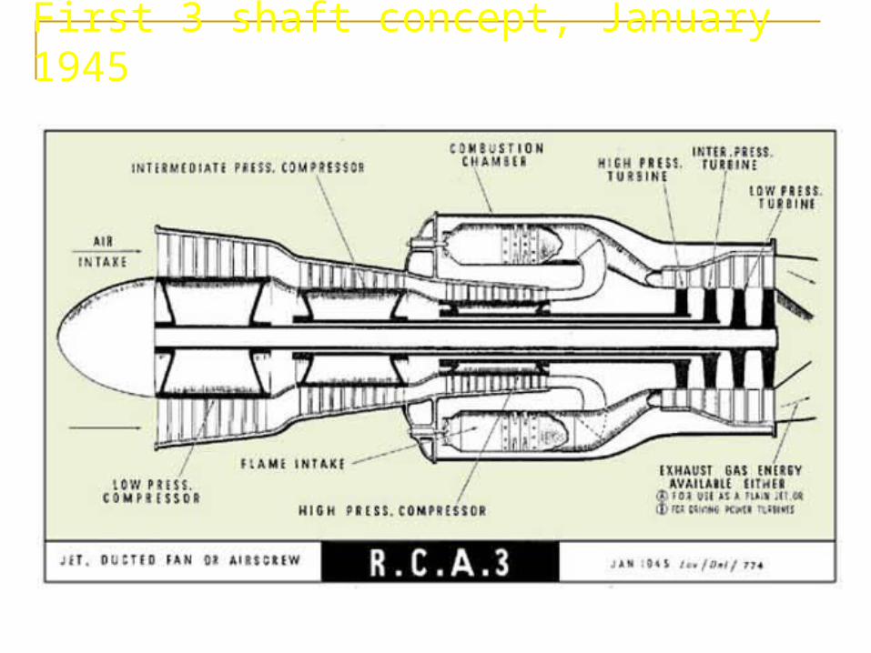
First 3 shaft concept, January 1945

POWERTURBINE GEAR
BOX
Coberra 6000 Starting SequenceCoberra 6000 Starting Sequence
Typical ArrangementTypical Arrangement
Roll RoyceRoll RoyceGas Generator Gas Generator
RT - 56RT - 56RT - 62RT - 62 Centrifugal Centrifugal
CompressorCompressor
GG TURBINES
GG COMBUSTOR
GG COMPRESSORS
AIRINTAKE
RB211RB211
HPIP

Steam engine

COGAG Combined gas turbine and gas
turbine (COGAG) is propulsion system for ships using two gas turbines connected to a single propeller shaft.
A gearbox and clutches allow either of the turbines to drive the shaft or both of them combined.
Using one or two gas turbines has the advantage of having two different power settings.
Since the fuel efficiency of a gas turbine is best near its maximum power level, a small gas turbine running at its full speed is more efficient compared to a twice as powerful turbine running at half speed, allowing more economic transit at cruise speeds.

Diesel engine
Electric drive Electric drive transmissions have a higher specific fuel consumption, specific
weight and volume than mechanical drive systems, but has advantages in arrangement which may compensate for these disadvantages.
Advanced technology motors can be located very close to and on line with the propulsors, at the extreme aft end of the ship, or in external pods.
Electrical generator sets can be optimally spaced around the ship and electrically connected. In the longer term, combined with fuel cells, SFC, specific weight and volume are comparable with gas turbine and diesel prime movers for direct drive systems.
Zone Concept : The concept of dividing future classes of ship into zones to maximize
survivability also extends to the power system. Each zone would be autonomous and include ventilation systems, cooling
systems, power distribution and other services which could be affected by damage to another part of the ship.
At least two supplies would be provided for all essential loads. Current classes, using split generation and distribution, rely on the provision of normal and alternative supplies via Automatic Change-Over Switches

Fuel cell The fuel cell stack operates by utilizing electrochemical reactions between
an oxidant (air) and a fuel (hydrogen), with two electrodes separated by a membrane.
The voltage of the fuel cell output can be controlled by a converter and it is therefore able to connect to any point in the ship service or propulsion distribution system.
The fuel cell stack is modularity give redundancy advantage. It also has the additional advantages of zero noxious emissions, and low thermal and acoustic signatures.
In the short term the fuel cell system is required to use marine diesel fuel. Diesel fuel will require reforming within the fuel cell stack, or using an external process, to produce a hydrogen rich gas which the fuel cell stack is capable of processing.
The reformer will clearly add both size, weight and complexity to the fuel cell system. In the longer term technologies such as the Solid Oxide Fuel Cell (SOFC) are contenders, which are more forgiving of impurities and can use a fuel available world-wide, either methanol or gasoline.
Storage option The technologies being assessed for energy storage include are
electro-chemical batteries (both conventional and advanced), regenerative fuel cells (otherwise known as redox flow cells ) Superconducting Magnetic Energy Storage (SMES) and Supercapacitors.
Regenerative fuel cells store or release electrical energy by means of a reversible electrochemical reaction between two salt solutions (the electrolytes). The reaction occurs within an electrochemical cell.
The cell has two compartments, one for each electrolyte, physically separated by an ion-exchange membrane.
In contrast to most types of battery system, the electrolytes flow into and out of the cells and are transformed electrochemically inside the cells. The power is therefore determined by the size of the cell but the endurance is determined by the size of the two electrolyte tanks

Storage system

Prime movers and emission All prime movers are potentially compliant with emerging emission
requirements, however, complexity for achieving compliance varies with prime mover and fuel type.
Diesels require the most attention to emissions control followed at some distance by gas turbines, where ultra low emissions levels have been achieved for land-based systems.
Fuel cells emit the lowest levels of pollutants of all the prime movers
Heavier fuel cell systems and diesels represent larger machinery and structural weight.
Fuel cells can be used as a prime mover in an Integrated Full Electric Propulsion (IFEP) system providing DC electrical power output, and are being developed as a replacement for diesel generators and gas turbine alternators.

Sail and solar power ship

Skysail
Propulsion system layout
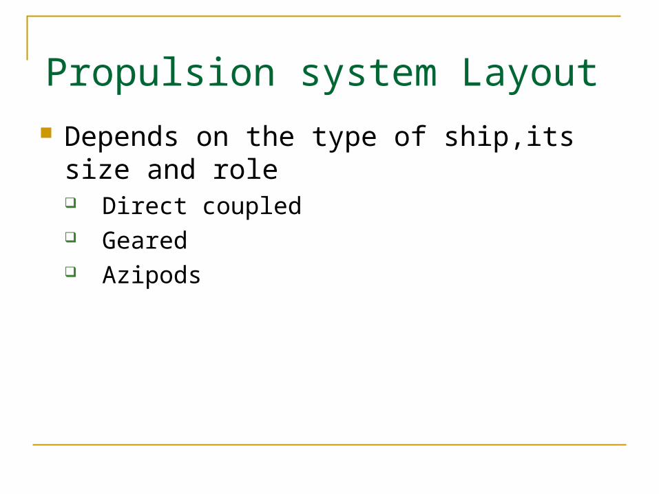
Propulsion system Layout Depends on the type of ship,its size and role
Direct coupled Geared Azipods

97

98
Ship Drive Train and Power
Ship Drive Train System
Engine ReductionGear
Bearing Seals
ScrewStrut
BHP SHP DHP
THP
EHP

99
Brake Horse Power (BHP)
- Power output at the shaft coming out of the engine before
the reduction gears
Shaft Horse Power (SHP)
- Power output after the reduction gears
- SHP=BHP - losses in reduction gear
Horse Power in Drive Train
Ship Drive Train and Power

100
Delivered Horse Power (DHP)
- Power delivered to the propeller
- DHP=SHP – losses in shafting, shaft bearings and seals
Thrust Horse Power (THP)
- Power created by the screw/propeller
- THP=DHP – Propeller losses
Relative Magnitudes
BHP>SHP>DHP>THP>EHP
E/G R/GBHP SHP Shaft
Bearing Prop.DHP THP EHP
Hull
Ship Drive Train and Power

101
Effective Horse Power (EHP)
• EHP : The power required to move the ship hull at a given
speed in the absence of propeller action
(EHP is not related with Power Train System)
• EHP can be determined from the towing tank experiments at
the various speeds of the model ship.
• EHP of the model ship is converted into EHP of the full scale
ship by Froude’s Law.
VTowing Tank Towing carriage
Measured EHP

102
Effective Horse Power (EHP)
0
200
400
600
800
1000
Effe
ctive
Ho
rse
po
we
r, E
HP
(H
P)
0 2 4 6 8 10 12 14 16 Ship Speed, Vs (Knots)
POWER CURVEYARD PATROL CRAFT
Typical EHP Curve of YP
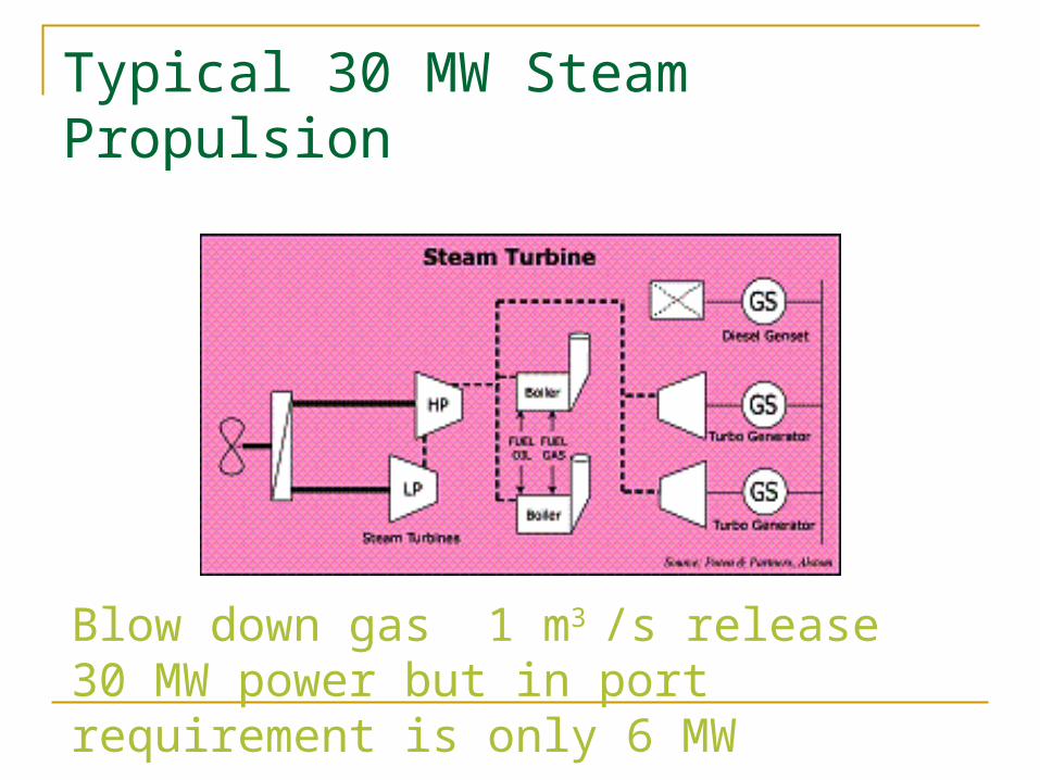
Typical 30 MW Steam Propulsion
Blow down gas 1 m3 /s release 30 MW power but in port requirement is only 6 MW

Typical Diesel Propulsion
Main and aux power sources separate and independent, re-liquefaction (5 MW)

Typical Diesel Propulsion
Main and aux power sources separate and independent, re-liquefaction (5 MW)

Typical Diesel Propulsion
Main diesel engines drive aux generators

Typical Diesel Propulsion

Typical Schematic of IEPS

Layout of Typical IEPS

Medium speed 4-s diesel

Pictorial View of First IEPS

Hull

113
Bulbous Bow
Wave-Making Resistance (cont)
Summary
Development of marine engineering system Common terms of marine engineering system Overview of marine engineering system Overview of marine engines - LO, Fuel Valve
cooling, Cylinder LO etc., Overview of marine propulsion layout