
Marine CFD applications using OpenFOAM solvers for marine CFD analysis • 6DOF/2DOF solver:...
29
Marine CFD applications using OpenFOAM Andrea Penza, CINECA 27/03/2014
-
Upload
nguyenkiet -
Category
Documents
-
view
234 -
download
4
Transcript of Marine CFD applications using OpenFOAM solvers for marine CFD analysis • 6DOF/2DOF solver:...

Marine CFD applications
using OpenFOAM
Andrea Penza, CINECA
27/03/2014

Contents
• Background at CINECA: LRC experience
• CFD skills
• Automatic workflow
• Reliability workflow

OpenFOAM solvers for marine CFD analysis
• 6DOF/2DOF solver: "interDyMFoam (dynamics, transient, optional wave motion)"fully explicit mules: CFL mandatory"
"• Unsteady 0DOF:"
interFoam (transient captive) "
• 0DOF (captive): "LTSInterFoam (Local Time Stepping (quasi-static hypothesis), suitable for automation and large computational campaign)"

OpenFOAM: CFD mandatory

CFD Model ① High Reynolds
simulation: RANS model employed
② Turbulence model: k-ω SST
③ Wallfunction enabled: y+ ≈ 70
Ø Standard DTMB-5415 bare hull modeled

CFD model for marine applications

CFD comparison method

Unsteady captive - CFD Results
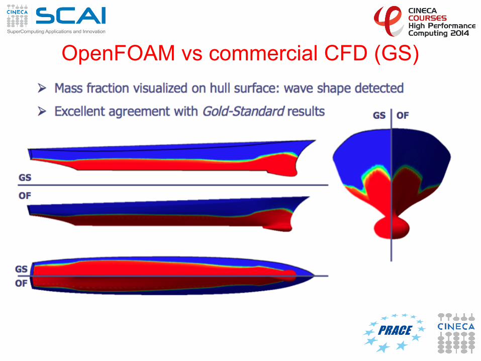
OpenFOAM vs commercial CFD (GS)

OpenFOAM velocity field
Ø Symmetry well caught by the solver in the velocity field computations

Pressure field over hull

Free surface visualization

CFD results: agreement with theory

DTMB-5414: half hull simulations

Two phase High Reynolds RANS
CFD analysis Free surface
simulation of high performance boat
(AC72 kat) and appendages
3D complex geometries
meshing Highly automated
meshing process of 3D complex
shapes; fully-structured, hybrid or unstrucutured mesh on problem
demand.
Aerodynamics Aerodynamic of high Reynolds number RANS
simulation of 3D bodies; high parallel CFD computations
2D airfoil design Wing section
efficient RANS simulation. Airfoil
design optimization based on RANS
code data
CFD skills applied to AC72 issues

Marine CFD automatic workflow

OpenFOAM automatic workflow evaluation
① Accuracy
② Scalability
③ Reliability
Ready to CFD production on HPC cluster
Automation

Wigley-hull
Ø Description: widely used in marine engineering for validation of measures
Ø Standard reference

Accuracy: CFD vs experimental
Ø Wigley-hull wave elevation @ different Froude number
Accuracy: mesh sensitivity
Ø Fixed Froude number. On purpose degradation of mesh reducing number of cells to investigate how total computed forces become (in)accurate
Ø Considerable advantages in elapsed time required
Ø Mesh size range [% cells respect to gold-standard mesh]: 5.0% - 8.0% - 36.% - 100.% (gold-standard)
Ø Cores range: 12 – 24 @ PLX, CINECA cluster

Accuracy: mesh sensitivity
Ø Reducing mesh size in not critical for the absolute convergence but just delays it.
Ø 5% size mesh respect to GS produces a 3%
discrepancy in the total computed drag Ø 5% size mesh respect to GS requires just
2h @ 12 cpu to reach convergence
Ø User choice: different accuracy, different mesh size, different cost.
Mesh-size F value [N]
F diff%
100% 3,03 Used-as-GS
36% 3,05 0,6%
8% 2,98 1,6%
5% 2,93 3,3%

Scalability Ø Different elapsed time due to different used computational
cores
Ø Fixed mesh size: 1.7 M cells
Ø Cores range: 12 – 24 – 36 – 48 – 72 @ PLX, CINECA cluster
Ø Fixed number of iterations: 5000 (up to convergence)
Ø Key value indices: elapsed-time, speedup, efficiency
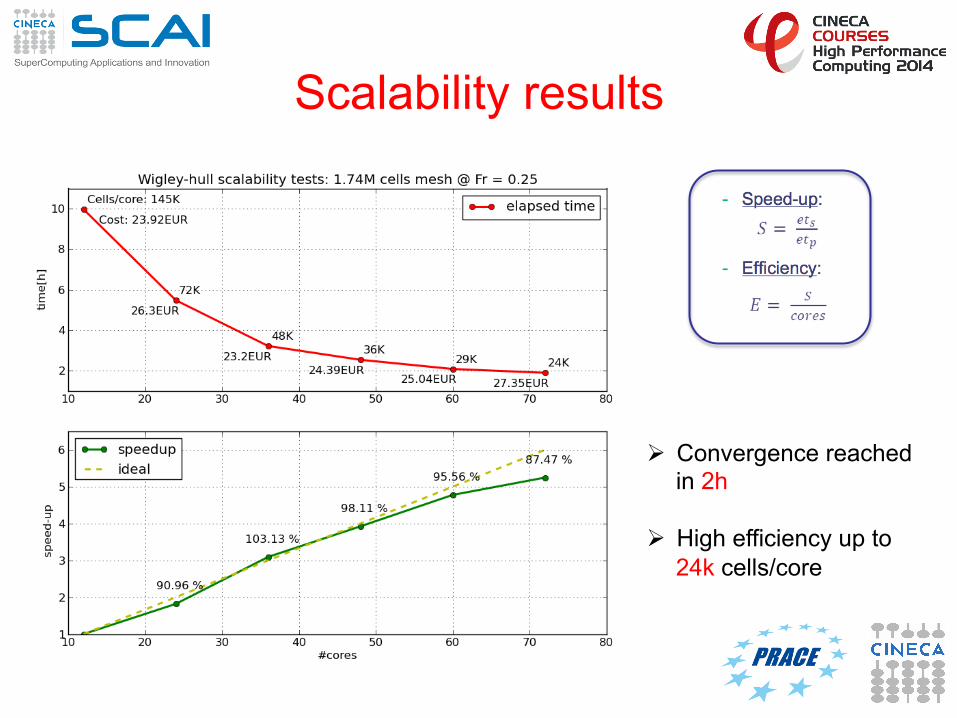
Scalability results
Ø Convergence reached in 2h
Ø High efficiency up to 24k cells/core

Reliability
Ø Different computed forces due to different Froude number e.g. inlet velocity
Ø Fixed mesh size: 1.7 mln cells Ø Fixed number of cores: 36 @ PLX, CINECA cluster Ø Froude number range: 0.250 0.267 0.289 0.316 0.354 0.408 Ø Key value indices: total forces, viscous forces, pressure forces, wave
height

Reliability: results Ø Stable solution reached
within 4s (4k iteration for LTS solver)
Ø Fixed cut-off at 6s.
Ø Stable means are computed in the selected range 4s – 6s, so 4h @ 36 cpu exploiting best scalability

Wave elevation (α = 0.5)

Pressure & axial velocity
Pressure over boat hull Axial (x) velocity over wave 3D surface
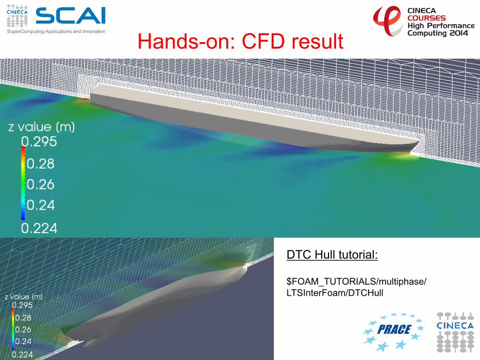
Hands-on: CFD result
DTC Hull tutorial: $FOAM_TUTORIALS/multiphase/LTSInterFoam/DTCHull

Hands-on: OpenFOAM commands ① CAD transformation: scaling, trim, sink
Ø surfaceTransformPoints –scale -yawPitchRoll -translate
② Setup constants:
Ø Edit constant/transportProperties Ø Edit constant/RASProperties
③ Setup BCs:
Ø Edit 0.org files
④ Setup free surface initial position:
Ø Edit system/setFieldDict Ø Run setFields
⑤ Decompose domain: Ø Edit system/decomposeParDict Ø Run decomposePar
⑥ Run solver:
Ø mpirun –np … LTSInterFoam -parallel
⑦ Reconstruct domain Ø Run reconstructPar


![3D FE and 2DOF simulations of ground shock … compare the experimental results from [3]-[4] with simulations carried out in AUTODYN-3D [6] and a simplified 2DOF model. Earlier comparisons](https://static.fdocuments.net/doc/165x107/5ad23b847f8b9a72118ce29d/3d-fe-and-2dof-simulations-of-ground-shock-compare-the-experimental-results.jpg)

