
Marine Assessment for New Cable Lay by FibraLink Jamaica Limited.
147
MARINE ASSESSMENT FIBRALINK NEW CABLE LAY [Prepared for Fibralink Jamaica Limited] NOVEMBER 2007 CONRAD DOUGLAS & ASSOCIATES LIMITED 14 Carvalho Drive Kingston 10 Jamaica W.I. Telephone: 929 0023/0025/8824 Email: [email protected]; [email protected]; [email protected]
Transcript of Marine Assessment for New Cable Lay by FibraLink Jamaica Limited.

MARINE ASSESSMENTFIBRALINK NEW CABLE LAY[Prepared for Fibralink Jamaica Limited]
NOVEMBER
2007
CONRAD DOUGLAS & ASSOCIATES LIMITED14 Carvalho Drive
Kingston 10
Jamaica W.I.
Telephone: 929 0023/0025/8824
Email: [email protected];

MARINE ASSESSMENT
Fibralink New Cable Lay
September 2007
Prepared for:
Fibralink Jamaica Limited

Fibralink New Cable Lay Table of Contents
Conrad Douglas & Associates LTD CD*PRJ 1056/07 i
Table of Contents
Page Number
Table of Contents ............................................................................................................... i
List of Tables ............................................................................................................................ ivList of Figures............................................................................................................................ v List of Plates ............................................................................................................................ viiList of Appendices.................................................................................................................. viii
1 Executive Summary ................................................................................................. 1-1
1.1 Introduction.................................................................................................................. 1-11.2 Conclusion ................................................................................................................... 1-3
2 Project Description................................................................................................... 2-1
2.1 Introduction.................................................................................................................. 2-12.2 Background.................................................................................................................. 2-2
2.2.1 Regional Cable History........................................................................................ 2-32.3 The Proposed Project ................................................................................................... 2-4
2.3.1 The Cable ............................................................................................................. 2-42.3.2 Proposed Implementation .................................................................................... 2-72.3.3 Landing Sites...................................................................................................... 2-102.3.4 Marine Ducts and Near-Shore Manhole (NSM) Design and Construction
Methodology ...................................................................................................................... 2-202.3.5 Recommended Fibre-Optic Cable Installation Techniques ............................... 2-282.3.6 Cable Repair Techniques ................................................................................... 2-352.3.7 Waste Streams .................................................................................................... 2-38
3 Legislative and Regulatory Framework................................................................... 3-1
3.1 Introduction.................................................................................................................. 3-13.2 National Policies .......................................................................................................... 3-23.3 Applicable Legislation ................................................................................................. 3-2
3.3.1 The Natural Resources Conservation Authority Act, 1991.................................. 3-23.3.2 The Wildlife Protection Act, 1945........................................................................ 3-63.3.3 The Beach Control Act, 1956............................................................................... 3-63.3.4 The Town and Country Planning Act .................................................................. 3-73.3.5 The Public Health Act, 1985 ................................................................................ 3-93.3.6 The Jamaica National Heritage Trust Act, 1985 ............................................... 3-103.3.7 The National Solid Waste Management Authority Act, 2001 ............................ 3-103.3.8 Draft National Building Code for Jamaica, 2007 ............................................. 3-103.3.9 St. Thomas Parish Development Plan, .............................................................. 3-11
3.4 International Policy.................................................................................................... 3-113.4.1 Agenda 21 .......................................................................................................... 3-11
4 Analysis of Alternatives........................................................................................... 4-1

Fibralink New Cable Lay Table of Contents
Conrad Douglas & Associates LTD CD*PRJ 1056/07 ii
4.1 Introduction.................................................................................................................. 4-14.2 No-Action Alternative ................................................................................................. 4-14.3 Landing Site Alternatives ............................................................................................ 4-1
4.3.1 Bull Bay, St Andrew Alternatives......................................................................... 4-14.3.2 Prospect - Morant Point, St Thomas Alternatives ............................................... 4-2
4.4 Technology Alternatives.............................................................................................. 4-34.4.1 Radio .................................................................................................................... 4-44.4.2 Telephony ............................................................................................................. 4-44.4.3 Satellite Data Transmission ................................................................................. 4-5
5 Description of the Environment............................................................................... 5-1
5.1 Physical Environment .................................................................................................. 5-15.1.1 Meteorology ......................................................................................................... 5-15.1.2 Hydro- and Geophysical Environment ................................................................ 5-4
5.2 Hazard and Risk Assessment ....................................................................................... 5-75.2.1 Offshore Cable Operations .................................................................................. 5-75.2.2 Onshore Cable Operations .................................................................................. 5-85.2.3 Seismic Vulnerability ........................................................................................... 5-95.2.4 Hurricane Vulnerability..................................................................................... 5-165.2.5 Flooding Potential ............................................................................................. 5-185.2.6 Overall Assessment of Natural Hazard Vulnerability of Sites........................... 5-19
5.3 Biological Environment ............................................................................................. 5-205.3.1 Bull Bay, St. Andrew .......................................................................................... 5-205.3.2 Prospect, St. Thomas.......................................................................................... 5-23
6 Socio-Cultural Environmental ................................................................................. 6-1
6.1 Introduction.................................................................................................................. 6-16.2 Methodology................................................................................................................ 6-16.3 Survey Findings ........................................................................................................... 6-3
6.3.1 Segment 1: Bull Bay Proposed Landing Site ....................................................... 6-36.3.2 Segment 2: Prospect Proposed Landing Site....................................................... 6-66.3.3 Impact on the Marine Community (Fishermen, Bathers etc.) ............................. 6-96.3.4 Interpretation ..................................................................................................... 6-11
7 Determination of the Potential Impacts of the Proposed Project............................. 7-1
7.1 Introduction.................................................................................................................. 7-17.2 Potential Impacts [Physical, Biological, Socio-Cultural] ............................................ 7-4
7.2.1 Aesthetics ............................................................................................................. 7-47.2.2 Water Quality/Surface Water Hydrology and Groundwater ............................... 7-47.2.3 Air Quality ........................................................................................................... 7-47.2.4 Noise & Vibration ................................................................................................ 7-57.2.5 Wildlife & Vegetation Resources ......................................................................... 7-57.2.6 Employment & Socio-Economic Impacts............................................................. 7-67.2.7 Solid Waste........................................................................................................... 7-77.2.8 Occupational Health and Safety .......................................................................... 7-7
7.3 Impact Identification and Mitigation Matrices ............................................................ 7-8

Fibralink New Cable Lay Table of Contents
Conrad Douglas & Associates LTD CD*PRJ 1056/07 iii
8 Environmental Management and Monitoring Plan.................................................. 8-1
8.1 Introduction.................................................................................................................. 8-18.2 Pre-Construction Phase................................................................................................ 8-18.3 Construction Phase....................................................................................................... 8-2

Fibralink New Cable Lay Table of Contents
Conrad Douglas & Associates LTD CD*PRJ 1056/07 iv
List of Tables
Page Number
Table 2-1: Potential Cable Crossings........................................................................................... 2-3
Table 2-2: Typical Shore End Equipment List .......................................................................... 2-33
Table 2-3: Percentage of Failure Causes for 380 Reported Cable Faults .................................. 2-35
Table 3-1: Summary of the Applicable Legislation and the Responsible Agencies.................... 3-1
Table 5-1: 10% Probability Exceedance in any 50 year Period of Three Earthquake Parameters
for the Proposed Landing Sites .................................................................................................. 5-11
Table 5-2: Mercalli Scale........................................................................................................... 5-11
Table 5-3: Kingston Central Port Wind Results (knots): Maximum Likelihood Estimates and
Upper Prediction Limits for Various Return Periods (1 minute sustained wind at 10 meters above
ground)....................................................................................................................................... 5-16
Table 5-4: Kingston Central Port Storm Surge Results (meters): Maximum Likelihood Estimates
and Upper Prediction Limits for Various Return Periods.......................................................... 5-17
Table 5-5: Kingston Central Port Wave Height Results (untransformed deep water significant
wave height in meters): Maximum Likelihood Estimates and Upper Prediction Limits for
Various Return Periods. ............................................................................................................. 5-17
Table 6-1: Enumeration Districts Surveyed................................................................................. 6-1
Table 6-2: Age and Years of Residency within each Community/ED ........................................ 6-4
Table 6-3: Age and Years of Residency within each Community/ED ........................................ 6-7
Table 7-1: Potential Sources of Environmental Impacts ............................................................. 7-2
Table 7-2: Impact Identification Table - Bull Bay, St. Andrew .................................................. 7-8
Table 7-3: Impact Identification Table - Prospect, St. Thomas................................................... 7-9
Table 7-4: Impact Mitigation Table – Prospect & Bull Bay..................................................... 7-10

Fibralink New Cable Lay Table of Contents
Conrad Douglas & Associates LTD CD*PRJ 1056/07 v
List of Figures
Page Number
Figure 2-1: Proposed and Existing Regional Fibre-Optic Cable Connections ............................ 2-3
Figure 2-2: Fibre-Optic Cable Cross-Section .............................................................................. 2-5
Figure 2-3: Typical Cross-section of a single armoured sub-marine fibre optic cable (Not to
Scale)............................................................................................................................................ 2-6
Figure 2-4: Articulated Piping to Protect the Submarine Cable .................................................. 2-7
Figure 2-5: Typical Equipment Building Layout – Plan and Front End Elevations.................. 2-11
Figure 2-6: Typical Equipment Building Layout – Side End Elevations .................................. 2-12
Figure 2-7: Typical Equipment Building Structural Design – Key Structural Design Areas
Highlighted ................................................................................................................................ 2-13
Figure 2-8; Typical Equipment Building Structural Design – Detailed overview of Key Structural
Design Areas.............................................................................................................................. 2-14
Figure 2-9: Shoreline Baseline................................................................................................... 2-15
Figure 2-10: New Bull Bay Landing Site [Google Aerial Imagery] ......................................... 2-16
Figure 2-11: New Bull Bay Landing Approach......................................................................... 2-17
Figure 2-12: Shoreline at Prospect............................................................................................. 2-18
Figure 2-13: Prospect Landing Site [Google Aerial Imagery]................................................... 2-19
Figure 2-14: Prospect Landing Approach.................................................................................. 2-19
Figure 2-15: Proposed Cable Station Sites ................................................................................ 2-20
Figure 2-16: Trencher in Operation ........................................................................................... 2-22
Figure 2-17: Typical Manhole Detail ........................................................................................ 2-24
Figure 2-18: Trenching Details.................................................................................................. 2-25
Figure 2-19: Bull Bay - Location of Manhole in Proximity to roads and buildings.................. 2-25
Figure 2-20: Prospect - Proposed Manhole Location at Ocean View Close ............................. 2-26
Figure 2-21: Back Haul - Trench Cross-Section........................................................................ 2-27
Figure 2-22: Back Haul - Hand Hole Section............................................................................ 2-27
Figure 2-23: Reinstated Roadways ............................................................................................ 2-28
Figure 2-24: Typical Deck Layout............................................................................................. 2-30
Figure 5-1: Average Annual Rainfall for the Palisadoes, St. Andrew, 2000-2006 ..................... 5-2
Figure 5-2: Average Annual Rainfall for Morant Point, St. Thomas, 2000-2006 ....................... 5-2

Fibralink New Cable Lay Table of Contents
Conrad Douglas & Associates LTD CD*PRJ 1056/07 vi
Figure 5-3: Average Wind Speed per Year along the South-East coast of Jamaica, 2000-2006 5-3
Figure 5-4: Hydrostratigraphic Map showing the two sites: Bull Bay and Prospect................... 5-6
Figure 5-5: Tectonic Plates in the Caribbean region ................................................................... 5-9
Figure 5-6: Epicentres of Earthquakes Occurring Between 1998 and 2001 In The Vicinity Of
Jamaica....................................................................................................................................... 5-10
Figure 5-7: Horizontal Ground Acceleration in Jamaica........................................................... 5-13
Figure 5-8: Maximum Mercalli Intensity in Jamaica ................................................................ 5-13
Figure 5-9: Horizontal Ground Velocity in Jamaica.................................................................. 5-14
Figure 5-10: Land Slide Susceptibility Map for Bull Bay, St. Andrew Site ............................. 5-15
Figure 5-11 Extent of 2001 Flooding in Bull Bay ..................................................................... 5-19
Figure 5-12: Substrates Observed / Interpreted Along Proposed Alignment [Base Image 1991
Aerial Image – Survey Dept.] .................................................................................................... 5-23
Figure 6-1: Enumeration Districts Surveyed for Bull Bay Landing Site, St. Andrew................. 6-2
Figure 6-2: Enumeration Districts Surveyed for Prospect Landing Site, St. Andrew ................. 6-3
Figure 6-3: Perceived Impact of Fibre Optic Cables ................................................................... 6-5
Figure 6-4: Technology in Home................................................................................................. 6-6
Figure 6-5: Perceived Impact of Fibre Optic Cables ................................................................... 6-8
Figure 6-6: Technology in Home................................................................................................. 6-9
Fibralink New Cable Lay Table of Contents
Conrad Douglas & Associates LTD CD*PRJ 1056/07 vii
List of Plates
Page Number
Plate 2-1: Horizontal Direction Drill - Ditch Witch JT2720 ..................................................... 2-21
Plate 2-2: Illustration of Installation from Ship with a Sheave.................................................. 2-30
Plate 2-3: Illustration of Installation with a Winch on the Shore; Buoyed Cable on the Right. 2-31
Plate 2-4: Illustration of Installation Using a Landing Craft ..................................................... 2-32
Plate 5-1: Beach character [Note: retaining wall approximately 30 m from shoreline] ............ 5-20
Plate 5-2: View from the shoreline (Looking northwest) .......................................................... 5-21
Plate 5-3: New Little Copa Club Parking Lot............................................................................ 5-22
Plate 5-4: Vegetation at the New Little Copa Club ................................................................... 5-22
Plate 8-1: Proposed Alignment in Waters <30m in Depth ..........................................................XII
Plate 8-2: Substrate / Benthic Lifeforms Observed Along Proposed Alignment at Prospect, St.
Thomas - Waypoints 5 & 7........................................................................................................ XIII
Plate 8-3: Identification of Benthic Lifeforms Observed along Proposed Alignment – Encrusting
and Plating Corals ...................................................................................................................... XIV
Plate 8-4: Identification of Benthic Lifeforms Observed along Proposed Alignment – Plating and
Boulder Corals .............................................................................................................................XV
Plate 8-5: Mobile Lifeform Observed along Proposed Alignment............................................ XVI
Plate 8-6: Identification of Benthic Lifeforms Observed along the Proposed Alignment -
Waypoint 2................................................................................................................................XVII
Plate 8-7: Identification of Benthic Lifeforms Observed along the Proposed Alignment -
Waypoint 8 & 9........................................................................................................................XVIII

Fibralink New Cable Lay Table of Contents
Conrad Douglas & Associates LTD CD*PRJ 1056/07 viii
List of Appendices
Page Number
Appendix I: Approved Marine Assessment Scope of Detail ........................................................... I
Appendix II: Fibralink Licence & Signature Page Scan............................................................ VIII
Appendix III: Project Team ........................................................................................................... X
Appendix IV: Marine Photo-Inventory........................................................................................XII

Fibralink New Cable Lay 0BExecutive Summary
Conrad Douglas & Associates LTD Insert Project Number
EXECUTIVE SUMMARY

Fibralink New Cable Lay 0BExecutive Summary
Conrad Douglas & Associates LTD CD*PRJ 1056/07 1-1
1 Executive Summary
1.1 Introduction
Fibralink Jamaica Limited is planning to expand their existing submarine fibre-optic network to
maintain network diversity and reliability, by constructing a sub-sea fibre cable connection
between Boca Raton, Florida to Columbia via Jamaica.
This will provide a high-capacity fibre-optic connection between the United States (US) and
Jamaica, and Jamaica and South America. The project will see an efficient communications
system being put in place that improves on quality and reliability. The project is designed to
minimize network contingencies such as potential data transmission disruptions due to network
cuts and outages, and natural disasters such as hurricanes, through a redundant network.
The project will provide an unrepeatered spur to Jamaica and improve the existing physical
diversity; the landing areas proposed will be east of the existing AT&T Bull Bay landing utilized
by FibraLink on the south coast. Under FibraLink’s license, physical diversity is required from
its existing AT&T Bull Bay landing. Additionally, to provide synergies between Columbus
Networks (Bahamas) and Flow Jamaica, the new landing at Prospect is in keeping with plans for
a new Flow hub.
This proposed fibre-optic connection will improve and provide additional data transmission
capability, increased suppliers and reduced costs, and supply the increasing demand for
electronic communications (phone, facsimile, email, Internet) to the eastern end of the island.
The projects purpose is to employ marine cable installation technology to install a submarine
fibre-optic cable at the following proposed landing sites:
• Bull Bay, St. Andrew, and
• Prospect, St. Thomas
The project will use state-of-the-art cable installation technology to provide for the maximum
possible integrity and safety of the installed cable. The proposed work covered in this Marine
Assessment involves:

Fibralink New Cable Lay 0BExecutive Summary
Conrad Douglas & Associates LTD CD*PRJ 1056/07 1-2
Explanations of the technology, routing and process of deployment of the cable
The environmental setting and baseline for the proposed submarine cable expansion
included studies, analyses and assessments on:
o Cable type, cable laying methods
o Solid and hazardous waste management practice
o Routing of cables and associated risks of proposed actions
o Analysis of Alternatives
o Impact identification
o Impact mitigation
o Structural integrity testing of cable.
The potential negative environmental impacts of this study have been thoroughly addressed and
our findings indicate that those potential impacts identified can be considered negligible and of
short duration. These potentially negative impacts have been identified mainly during the
construction phase of the project and with good project management will be sufficiently
mitigated.
No new or unfamiliar major negative impacts or risks were identified. Additionally, several
potentially beneficial impacts have been identified that can be realized from the implementation
of this project.
The potential impacts identified for the pre-construction, construction and operating phases of
the proposed project include:
Negative
Minimal suspended solids during cable laying
Minimal noise and vibration during construction
Minimal aesthetics and transient change of land and marine use
Positive
Improved broadband access by commissioning new connections
Fibralink New Cable Lay 0BExecutive Summary
Conrad Douglas & Associates LTD CD*PRJ 1056/07 1-3
Potential vast increase in investment revenue and job creation due to improvements in the
telecommunications industry from this project.
No loss of biodiversity
No loss of archaeological and historical heritage resources
Improvement in construction methods through Horizontal Directional Drilling to
minimize the impact to coastal zone at landing site. This technology is a significant
improvement on trenching, previously practiced.
Any negative impacts identified will be effectively mitigated using traditional and state of the art
methods, as necessary, such as the use of the Horizontal Directional Drill and curbside trencher.
Several government agencies were contacted as well as various public interests throughout the
Marine Assessment process. This was done to present all parties with information on the project
to determine areas of potential conflict, and to encourage open dialogue on this very important
development project. Further, Fibralink has promised to provide the appropriate authorities with
As-Laid positions and charts for notification to the appropriate mapping agencies in the island.
An environmental management plan will be incorporated as well as a monitoring protocol for all
aspects from startup to operation.
1.2 Conclusion
The proposed expansion of the broadband network for Jamaica is planned to take place against a
background of improvements in the quality of broadband connection, increases in connectivity in
meeting the demand, decreases in cost for access to all, and the lessening of disruption due to
accidents or natural disasters.
The potential impacts identified if realized will be mitigated using proven technologies. No new
or unfamiliar environmental impacts or risks have been identified with the proposed project.
The proposed project represents a continuance of the large investment in telecommunications in
Jamaica and bears the potential for enormous macro and micro economic growth and
development as well as social benefits to Jamaica.

Fibralink New Cable Lay Project Description
Conrad Douglas & Associates LTD CD*PRJ 1056/07
PROJECT DESCRIPTION
Fibralink New Cable Lay Project Description
Conrad Douglas & Associates LTD CD*PRJ 1056/07 2-1
2 Project Description
2.1 Introduction
The installation of fibre optics is the preferred method of carrying voice, video, and data
communications. Its superior information-carrying capacity enables the use of applications that
require large amounts of bandwidth.
Fibre-optic cable allows for optimization of transmission equipment because it lacks the delay
found in satellite connections. Further, unlike satellite communications, fibre-optic cables are
insensitive to electromagnetic and/or atmospheric interference and offer a secure link because of
their relative immunity to eavesdropping.
To maintain network diversity and reliability, Columbus Networks through its Jamaican affiliate
Fibralink Jamaica Limited will be constructing a sub-sea fibre cable connecting Boca Raton,
Florida with Jamaica and Columbia.
To maintain an unrepeatered spur to Jamaica and physical diversity, two new landing sites are
envisioned. The landing area in Jamaica will be east of the existing AT&T Bull Bay landing
utilized by FibraLink on the south coast. Under FibraLink’s license, physical diversity is
required from its existing AT&T Bull Bay landing. Additionally, to provide synergies between
Columbus Networks and Flow Jamaica, the new landing will be sited in a region planned for a
Flow hub. Flow Jamaica, a subsidiary of Fibralink is the commercial supplier of data, voice and
video communications. Flow has identified Morant Bay as the most appropriate area for
construction of a hub and cable landing.
The Morant Point landing will be connected to FibraLink at the AT&T Bull Bay facility via an
unrepeatered festoon. For diversity reasons, there will be a new landing site east of the existing
AT&T Bull Bay landing. This second Bull Bay landing will be connected to FibraLink via a
newly constructed underground duct system.

Fibralink New Cable Lay Project Description
Conrad Douglas & Associates LTD CD*PRJ 1056/07 2-2
2.2 Background
FibraLink Jamaica Limited is a recently incorporated Jamaican company established with the
expressed purpose of building, owning and operating a sub-marine fibre-optic network to
provide broadband communication linkages for Jamaica to the rest of the world.
Following on the significant loss of broadband service to the island during Hurricane Ivan in
September of 2004, the need for additional and redundant fibre optic linkages to the island was
realized.
Pursuant to Section 13 and Section 78 of the Telecommunications Act, 2000, a licence for the
construction and operation of a Submarine Fibre Optic Cable Network was granted to FibraLink
Jamaica Limited on December 20, 2004 by the Minister of Commerce, Science and Technology,
the Honourable Phillip Paulwell. The licence stipulates that:
In granting a licence to FibraLink Jamaica, the Office of Utility Regulations (OUR) required that
all single points of failure be eliminated from the network. The first installation of landing points
in Jamaica was accomplished in 2006, namely:
Bull Bay – St. Thomas,
Ocho Rios – St. Ann, and
Montego Bay – St. James.
Figure 2-1 below shows the proposed routing and terrestrial connections of the proposed
redundant link to the network.

Fibralink New Cable Lay Project Description
Conrad Douglas & Associates LTD CD*PRJ 1056/07 2-3
Figure 2-1: Proposed and Existing Regional Fibre-Optic Cable Connections
2.2.1 Regional Cable History
Many submarine cables are installed throughout the Caribbean Region including the Bahamas
and Jamaica (Figure 2-1). The following is a list of known active and inactive cables that may be
crossed during this project. There is also the potential for a number of either scientific or
military sub-marine cables throughout the area. It is not envisioned that these cables will
interfere in any way with the proposed FibraLink cable connection.
Table 2-1: Potential Cable Crossings
System Name Details
TCS 1 In Service: 1990
San Juan, Puerto Rico Barnquilla, Columbia Santo Domingo, Dominican
Republic Kingston, Jamaica 2,593km at 140 Mb/s KHz
Maintenance Authorities: AT & T, MCI, Sprint

Fibralink New Cable Lay Project Description
Conrad Douglas & Associates LTD CD*PRJ 1056/07 2-4
System Name Details
ECFS In Service: Sept 1995
Maintenance Authorities: TSTT
ARCOS 1
(AMERICAS REGION
CARIBBEAN RING
SYSTEM)
Phase 1: In Service: September 2001
Hollywood, USA; Nassau, Bahamas; Cat Island, Bahamas; Crooked Island,
Bahamas; Puerto Plata, Dominican Republic; Punta Cana, Dominican Republic;
San Juan, Puerto Rico.
Florida Jamaica Out of service: retired 1992, 1963: 29 years of Service
Florida City, Florida, U.S.A. Kingston, Jamaica 1,545km at 384 + 384 KHz
Maintenance Authorities: AT & T, Jamaican International Telecommunications
Ltd.
Canal Zone Jamaica Out of service: Retired 1998, 1963: 34 years of service
Kingston, Jamaica Fort Sherman, Panama 1,150km at 384 + 384 KHz
Maintenance Authorities: AT&T, ITT Central American Cables & Radio
2.3 The Proposed Project
FibraLink proposes to construct and operate a fibre-optic sub-marine cable network linking Boca
Raton, Florida with Jamaica and Columbia and ultimately the world. Fibralink has experience
with installing fibre-optic cables in Jamaica having installed a new system in 2006.
2.3.1 The Cable
With over 20 submarine communication cables Caribbean waters, there has been no reported
negative impact on the environment. The routing of each of the new cables has been based on
avoiding any sensitive area such as coral reef and fish nurseries and proven techniques used
during the recent construction of the original segments between the Jamaica and the United
States of America and the Bahamas will be used for the installation.
The small size of the cable (Figure 2-2), the narrow path of the cable and the shortness of the
construction phase are the major factors limiting the potential for impacts.

Fibralink New Cable Lay Project Description
Conrad Douglas & Associates LTD CD*PRJ 1056/07 2-5
Figure 2-2: Fibre-Optic Cable Cross-Section
All non-repeatered armoured fibre-optic submarine cables are basically constructed in a similar
manner. Figure 2-3 below shows the typical components of such cables.

Fibralink New Cable Lay Project Description
Conrad Douglas & Associates LTD CD*PRJ 1056/07 2-6
Figure 2-3: Typical Cross-section of a single armoured sub-marine fibre optic cable (Not to Scale)

Fibralink New Cable Lay Project Description
Conrad Douglas & Associates LTD CD*PRJ 1056/07 2-7
To ensure longevity of the cable and to minimize the potential for breaks, it is important that the
cable is laid in areas of soft sand bottom, away from coral and other hard marine structures and
anchorages. Where necessary, the cable will be protected through the use of a boltless articulated
pipe. The incorporation of the articulated pipe will also provide a self burial method, thus
avoiding excessive disruption to the ocean floor (Figure 2-4).
Figure 2-4: Articulated Piping to Protect the Submarine Cable
2.3.2 Proposed Implementation
The proposed development will factor in the various phases of a development such the pre-
construction, construction and operational phases. This development similar to the previous
cable lay by Fibralink will require approvals and be subjected to the requirements as laid out by
law of the National Environment and Planning Agency (NEPA) and the respective Parish
Council as well as any other relevant authorities.
Site preparation and construction schedules will take into account the traditional rainy season
between May and October, including the hurricane season from June to November, during which
tropical storm systems may bring tropical storm/hurricane winds with the potential to a bring a
halt to all marine related works for a considerable period, and as such this project will be
factored this eventuality.
The project is proposed to be implemented during the first week of December 2007.

Fibralink New Cable Lay Project Description
Conrad Douglas & Associates LTD CD*PRJ 1056/07 2-8
During the pre-construction, construction, and operational phases employment will be for
various types of workers including; engineers, labourers (skilled and unskilled), suppliers of
goods and services, among others. The bulk of workers will be employed during the laying of the
cables within the near-shore environment, to include boat handlers, divers etc.
The proposed phases of the project are as follows:
Phase Description Proposed Time Period
1 – Pre Construction Siting and development of
nearshore infrastructure
including manholes and ducts
1 week, December 2008
2 – Construction [Cable Lay] Construction of nearshore
manhole and ducts using
horizontal directional drilling,
laying and verification of
cables using route markers,
pulling of cable through ducts
in nearshore waters, laying of
cable in offshore waters
4 6 weeks, December 2008
3 Operation Commissioning of fibre optic
cable
Earliest 2ndQuarter 2008
Activities to be undertaken in the various phases are outlined in the following sections.
Phase 1: Pre-Construction
Pre-construction activities include all site preparation activities such as
identifying nearshore manhole location at the respective landing sites, and recorded their
GPS coordinates
Verification with pre-survey coordinate locations, and positioning of horizontal
directional drill and associated equipment
Re-verification of cable lay route through dive survey to ensure no new obstacles are
present
Pre-construction waste that cannot be re-used, such as packing material and drill dredge will be
disposed of at an approved facility such as the Riverton City Landfill which serves the South-

Fibralink New Cable Lay Project Description
Conrad Douglas & Associates LTD CD*PRJ 1056/07 2-9
East region, and is managed by the MPM Waste Management Limited a regional division of the
National Solid Waste Management Authority (NSWMA).
Phase 2: Construction [Cable Lay]
Construction activities include all activities geared towards the laying of the fibre-optic cable
through ducts and on the seabed in the nearshore and offshore regions. All site works will be
executed in accordance with international accepted standards similar to previous cable lay in
Jamaica and elsewhere in the Caribbean as outlined in this report.
Fibralink and/or its Contractors will enter into discussion with the relevant authorities such as
NEPA and the Marine Police among others, where necessary, to ensure the public is protected
during the cable lay. Though the area is not an active marine traffic site, all precautions will be
taken to protect life and property during the laying of the fibre-optic cable.
Cleared material from the installation of the marine duct to receive the cable and material
removed in the construction of the nearshore manhole that will not be re-used will be disposed of
at an approved facility such as the Riverton City Landfill which serves the South-East region,
and is managed by the MPM Waste Management Limited a regional division of the National
Solid Waste Management Authority (NSWMA).
Cables will be laid from a ship holding position offshore. Cable will be brought towards the
landward duct location via small boat with cable attached to buoys prior to positioning on the
seafloor. Protection of any marine resources such as coral will be done by divers wherever
sensitive life-forms or marine interests are found in conjunction with inspectors from the relevant
authorities.
No cables will be laid on or across and coral formation to protect both the cable and the life-
forms.

Fibralink New Cable Lay Project Description
Conrad Douglas & Associates LTD CD*PRJ 1056/07 2-10
Phase 3: Operation
Operation activities include the commissioning of the cables into power, the completion of
station house, and connection to the existing Fibralink network. These activities represent the
end product of the development to be kept in-situ into perpetuity.
The proposed mitigation measures incorporated in the engineering design will prevent problems
of cable damage, damage to sensitive marine areas, most significantly loss of contact with the
rest of the world during severe storms as happened most recently in 2004 with hurricane Ivan.
Mitigation measures proposed for all phases of the project are outlined in the Impact
Identification and Mitigation section of this report (Section 7). Scheduled inspections and
maintenance of the cable is critical and will be address by the monitoring plan to be put in plan
as outlined later in this report (Section 8).
2.3.3 Landing Sites
FibraLink proposes two (2) landings to support the location of separate cables on the south coast
of the island. The proposed landing sites are:
Bull Bay, St. Andrew
Prospect, St. Thomas
Landing site refers to the location that the cable comes ashore and may not be the location of the
equipment building. In all cases, the equipment building will be located in a secured location
close to the distribution network. Equipment buildings are ideally located in proximity to the
landing site, with easy access to electricity and at an elevation in excess of 3 meters above sea
level. Buildings are of the standard concrete and steel and will meet building codes as stipulated
by the relevant authorities such as the St. Thomas Parish Council. The typical equipment
building layouts and structural designs are detailed in Figure 2-5 - Figure 2-8 below.

Fibralink New Cable Lay Project Description
Conrad Douglas & Associates LTD CD*PRJ 1056/07 2-11
Figure 2-5: Typical Equipment Building Layout – Plan and Front End Elevations

Fibralink New Cable Lay Project Description
Conrad Douglas & Associates LTD CD*PRJ 1056/07 2-12
Figure 2-6: Typical Equipment Building Layout – Side End Elevations

Fibralink New Cable Lay Project Description
Conrad Douglas & Associates LTD CD*PRJ 1056/07 2-13
Figure 2-7: Typical Equipment Building Structural Design – Key Structural Design Areas Highlighted

Fibralink New Cable Lay Project Description
Conrad Douglas & Associates LTD CD*PRJ 1056/07 2-14
Figure 2-8; Typical Equipment Building Structural Design – Detailed overview of Key Structural Design
Areas

Fibralink New Cable Lay Project Description
Conrad Douglas & Associates LTD CD*PRJ 1056/07 2-15
2.3.3.1 Bull Bay Landing Site
The coastline within 1 - 4 km east of the Bull Bay landing is primarily an informal settlement
area. Fishing activity is limited to small boat (canoe type) boats with nets, trawl and spear
fishing. Vessel anchoring in the area is limited or none.
The coordinates for the Bull Bay Landing site are:
North: 17° 56.553’
South: 076° 41.379’
The beach and nearshore is primarily coarse black sand which appears to deepen slowly without
any reefs present. It is similar to the existing Fibralink (AT&T) Bull Bay approach which is
mainly coarse sand and small boulders without any coral present. This landing site provides
excellent access for shore end activities (Figure 2-9).
Figure 2-9: Shoreline Baseline

Fibralink New Cable Lay Project Description
Conrad Douglas & Associates LTD CD*PRJ 1056/07 2-16
2.3.3.1.1 Physical Description
The location of the cable station is on Highway A4 in Bull Bay, which is approximately 7
kilometres east of the Harbour View round about, and ~1.7 km east of the existing Fibralink
cable station.
The cable route then goes under the coastal road west towards the cable station that is
approximately 35 m above sea level. All underground cable routes will utilize new and/or
existing ducts, minimising disruption to the environment.
The building is a typical cable station; no windows, flat roof, with parking and loading dock
access. This building is operational, no external modifications are necessary. The map and
pictures below show the proposed route into Bull Bay, landing site and environs at Bull Bay
(Figure 2-10 and Figure 2-1).
Figure 2-10: New Bull Bay Landing Site [Google Aerial Imagery]

Fibralink New Cable Lay Project Description
Conrad Douglas & Associates LTD CD*PRJ 1056/07 2-17
Figure 2-11: New Bull Bay Landing Approach
2.3.3.2 Prospect Landing Site
The coastline along this area has primarily shallow water less than 6 m water depth to a distance
from the shoreline varying from approximately 50 m – 300 m with breaking waves on the
seaward side where the depth appears to increase dramatically. Marine navigational charts
indicate a deep water channel between the reefs in the area. The bottom in this channel consists
mainly of sand. This channel may pose an increased difficulty during the landing of the cable
due to its orientation but does provide some protection against heavy seas from the south.
Fishing activity is limited to small boat (canoe type) boats with nets, trawl and spear fishing.
Limited or no vessel anchoring occurs in the area.
This entire area is within a developing community that can be described as organized middle/low
income. The shoreline is a fine sand beach and slopes gently towards the channel. The beach
manhole (BMH) location will be approximately 1.5 m above sea level and 10 m from the
shoreline (Figure 2-12). The distance to the proposed cable station site is 600 m.

Fibralink New Cable Lay Project Description
Conrad Douglas & Associates LTD CD*PRJ 1056/07 2-18
The coordinates for the Prospect Landing site is:
North: 17° 51.865’
South: 076° 20.450’
The site provides excellent access for shore end activities.
Figure 2-12: Shoreline at Prospect
2.3.3.2.1 Physical Description
The shoreline at Ocean View Close is primarily white sand and seagrass beds. The location of
the cable manhole will be within the community of Prospect, specifically Ocean View Close,
which is approximately 3 kilometres south-west of Port Morant or about 1 km east of Lyssons.
All underground cable routes will utilize new ducts and proven technology to minimise
disruption to the environment.
The cable station will serve as both a good sub sea cable station and a distribution point for
Flow’s HFC network. The proposed site has coordinates 17° 52.088’N, 076° 20.652’W at an
elevation of approximately 16m above sea level. The area is can best be described as a middle to
low income community. Cable & Wireless underground passes within 30 m of the site, and a
new Digicel tower site is within 60 m.
The map and pictures below show the proposed route into Bull Bay, landing site and environs at
Bull Bay (Figure 2-13 to Figure 2-15)

Fibralink New Cable Lay Project Description
Conrad Douglas & Associates LTD CD*PRJ 1056/07 2-19
Figure 2-13: Prospect Landing Site [Google Aerial Imagery]
Figure 2-14: Prospect Landing Approach

Fibralink New Cable Lay Project Description
Conrad Douglas & Associates LTD CD*PRJ 1056/07 2-20
Figure 2-15: Proposed Cable Station Sites
2.3.4 Marine Ducts and Near-Shore Manhole (NSM) Design and Construction
Methodology
2.3.4.1 Marine Ducts Design
To minimize the impact near the beach and address the issues related to possible use of the area
by fishermen and the public, the construction method most suitable was determined to be
Horizontal Directional Drilling (“HDD”). HDD is done from an approximate distance of 15 m
from the shoreline, thereby avoiding construction at the beach area.
This is an improved method of dealing with the nearshore compared with the trenching method
used in previous installations. It allows users of the beach to continue use and avoids the
negative aesthetic of trenching activities. The impact to the nearshore is also minimal.
The NSM will be constructed in the parking lot adjacent to the beach at the Bull Bay site, and
within the right-of-way at Ocean View Close (Dead-end), Prospect, and drill four (4) 95 mm
marine ducts that would extend beyond the lower water mark to a minimum distance of
approximately 150 m. The nominal depth of drilling will be approximately 3.6 m – 6.0 m.
Fibralink New Cable Lay Project Description
Conrad Douglas & Associates LTD CD*PRJ 1056/07 2-21
The HDD approach addresses concerns in relation to the following:
1. Environment;
2. Use of the public beach front and surrounding area;
3. Congestion that would result if the NSM were constructed at the shoreline; and
4. Avoids the disruptions that would result from shoreline excavations.
2.3.4.1.1 Construction Methodology
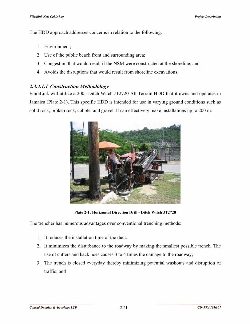
FibraLink will utilize a 2005 Ditch Witch JT2720 All Terrain HDD that it owns and operates in
Jamaica (Plate 2-1). This specific HDD is intended for use in varying ground conditions such as
solid rock, broken rock, cobble, and gravel. It can effectively make installations up to 200 m.
Plate 2-1: Horizontal Direction Drill - Ditch Witch JT2720
The trencher has numerous advantages over conventional trenching methods:
1. It reduces the installation time of the duct.
2. It minimizes the disturbance to the roadway by making the smallest possible trench. The
use of cutters and back hoes causes 3 to 4 times the damage to the roadway;
3. The trench is closed everyday thereby minimizing potential washouts and disruption of
traffic; and

Fibralink New Cable Lay Project Description
Conrad Douglas & Associates LTD CD*PRJ 1056/07 2-22
4. Due to reduced labour cost, it reduces the per metre construction cost of the trench.
Containing and minimizing costs helps ensure Jamaica can enjoy more competitively
priced products and services.
Figure 2-16 above shows the trencher in operation. In the back of the photo, the trencher is
cutting the trench. The work crew is cleaning the trench of excess material. Note that the cut is
placed as far from the roadway as possible and the road remains open to traffic. Below is an
example of a reinstated trench that was completed in a paved shoulder.
Figure 2-16: Trencher in Operation
Listed below is the equipment tool set
Item Qty Description
1 1 Ditch Witch HDD, Model JT2720 c/w transport trailer
2 1 Ford F650 Truck c/w mud mixer & 5000 litre water tank
3 1 FX30 Vac System c/w trailer
4 Ford F650 Truck c/w tools and drill rod inventory
5 1 Generators
6 2 50mm Electric Water Pumps
7 2 Jack Hammers
8 2 Compaction Rammers
9 1 Mobile trailer (for secure storage)

Fibralink New Cable Lay Project Description
Conrad Douglas & Associates LTD CD*PRJ 1056/07 2-23
Item Qty Description
10 1 Compressor
11 2 Wheel barrows
12 Lot Miscellaneous hand tools
13 30 Traffic cones
2.3.4.2 Near Shore Manhole & Back Haul Design
The marine ducts outlined above will terminate in a newly constructed Near Shore Manhole
(“NSM”). The NSM is constructed underground of reinforced concrete. To limit the disturbance
of the existing asphalt and to minimize the size of the excavation, a rubber tire backhoe will be
used. After the casting of the NSM, the excavation will be backfilled and compacted in lifts not
exceeding 300 m, the excess material will be removed from site and disposed at an approved
location. The backfilling will terminate a minimum of 50 mm below the existing asphalt; the
edges of the existing asphalt will be cut with a rotary saw and will receive a coating of liquid
asphalt before the asphalt pavement is reinstated. The NSM construction drawings are outlined
below (Figure 2-17 and Figure 2-18). Figure 2-19 and Figure 2-20 show the proposed location
for NSM at the selected sites.

Fibralink New Cable Lay Project Description
Conrad Douglas & Associates LTD CD*PRJ 1056/07 2-24
Figure 2-17: Typical Manhole Detail

Fibralink New Cable Lay Project Description
Conrad Douglas & Associates LTD CD*PRJ 1056/07 2-25
Figure 2-18: Trenching Details
Figure 2-19: Bull Bay - Location of Manhole in Proximity to roads and buildings

Fibralink New Cable Lay Project Description
Conrad Douglas & Associates LTD CD*PRJ 1056/07 2-26
Figure 2-20: Prospect - Proposed Manhole Location at Ocean View Close
The back haul of the land cable will be from the NSM to the cable stations. In St. Thomas it will
be via newly constructed underground fibre cable ducts along the roadway to a newly
constructed cable station proposed to be in the Morant Point area. This route is approximately
1.0 km long. There is existing water and sewer services along the route and will be coordinated
with the appropriate utilities authority. The installation will utilize purpose built trenching
machinery as described in Section 2.3.4.1.1 below.
There will be four 75 mm schedule 40 HDPE smooth PVC ducts. The ducts will be placed,
where possible, along the shoulder of the roadway to avoid disruption of the asphalted driving
surface. The excavation will be a maximum of 300 mm wide x 900 mm deep. Existing grades
will be maintained. To mitigate against potential washouts trenches will be closed daily.

Fibralink New Cable Lay Project Description
Conrad Douglas & Associates LTD CD*PRJ 1056/07 2-27
Figure 2-21: Back Haul - Trench Cross-Section
Hand holes for pulling the cable are placed at a minimum distance of 150 m apart and a
maximum of 300 m. The hand holes will be underground and will have inside dimensions of
1.05 m x 1.05 m x 0.85 m high. There will be 900 mm diameter lockable cast iron covers at each
hand hole. The hand holes are placed along the entire route for the primary purpose of pulling
cables into the ducts.
Figure 2-22: Back Haul - Hand Hole Section

Fibralink New Cable Lay Project Description
Conrad Douglas & Associates LTD CD*PRJ 1056/07 2-28
During the construction process all disruption will be reinstated to at least the standard of the
prior existing conditions. This includes backfill compaction and surface reinstatement (Figure
2-23).
Figure 2-23: Reinstated Roadways
2.3.4.2.1 Construction Methodology
The construction of the NSM will utilise a qualified local contractor experienced in such
activities. FibraLink’s affiliate, Flow Jamaica has an extensive list of qualified civil engineers
and contractors in Jamaica given its various expansion activities and ongoing cable TV
operations. FibraLink’s underground construction supervisor will oversee the entire process.
2.3.5 Recommended Fibre-Optic Cable Installation Techniques
This section details preliminary installation operations based on available information,
experience and standard technology
2.3.5.1 Route Surveys
A marine route survey has been conducted. The main objective of the marine route survey along
the projected cable routes was to develop sufficient bathymetric data to engineer and install the
fibre optic cable.
Diver swim surveys have also been conducted in the shallow water sections. This was done in
order to find an appropriate route; thereby avoiding any kind of obstacles and sensitive features
such as coral reefs and sea grass areas.

Fibralink New Cable Lay Project Description
Conrad Douglas & Associates LTD CD*PRJ 1056/07 2-29
Based on the information obtained from the Route Surveys, a suitable cable route was selected.
Illustrations of the inshore topography for the various selected route segments of the installation
are illustrated in Section 2.3 above.
2.3.5.2 Cable Installation
There are two separate operations required for cable installation, which are:
Shore end operations
Deep-water operations
The shore end activities are more site specific and are detailed based on the landing site. The
redundancy of the system allows for two-switch-traffic, where the two separate cables coming
into Jamaica are independent of each other so that the end user will not experience a disruption
in their service should any one cable becomes damaged and taken out of service for repairs.
2.3.5.2.1 Laying Vessel
A cable ship or converted flatback vessel (offshore supply) will be used to install the cable. If
using a flatback vessel, all the necessary equipment to manipulate the cable will be installed and
tested prior to the start of the operations. The typical vessel deck layout is represented below
(Figure 2-24). The main necessary equipment are as follows:
Cable tank with an internal cone respecting the minimum radii of curvature of the cable.
Caterpillar or linear cable engine (5 tons capacity).
20 feet container for splicing operations
Small crane (3 tons capacity)

Fibralink New Cable Lay Project Description
Conrad Douglas & Associates LTD CD*PRJ 1056/07 2-30
Chute
Dynamometer
Splicing AreaWinch
Caterpillar/Linear
Cable engine
Cable Guide
Cable Tank
Figure 2-24: Typical Deck Layout
2.3.5.2.2 Shore End Operations
The shore end superintendent will conduct a radio check prior to the start of cable pulling
operations. The key personnel will be called and asked to respond individually: vessel aft deck,
vessel bridge, winch operator, and dive boat. The shore superintendent will then commence the
shore end pulling operations (Plate 2-2).
Plate 2-2: Illustration of Installation from Ship with a Sheave

Fibralink New Cable Lay Project Description
Conrad Douglas & Associates LTD CD*PRJ 1056/07 2-31
The main lay vessel will be positioned near the seaward end of the directionally drilled pipe, in
approximately 11 m of water. The pull wire in the pipe will be retrieved by the diver and handed
off to the dive boat operator who in-turn will pass the line to the ship. A 28.575 mm (1 ”)
uniline will be attached to the pull wire and pulled ashore using the winch stationed near the
manhole (Plate 2-3).
When the uniline is secured on shore, the ship will be advised. The deck crew will attach the
cable to the uniline using a 6000 lb Miller or similar swivel and a Yale cable grip. The deck crew
will then advise the shore-end superintendent that pulling can proceed. The divers will follow the
cable end to the pipe and ensure that the cable enters the pipe smoothly. The deck crew aboard
ship will closely monitor payout tensions and draw speed as the cable is pulled into the manhole.
Shore end Manhole Winch Cable Lay RouteShore end Manhole Winch Cable Lay Route
Plate 2-3: Illustration of Installation with a Winch on the Shore; Buoyed Cable on the Right

Fibralink New Cable Lay Project Description
Conrad Douglas & Associates LTD CD*PRJ 1009/04 2-32
When the cable reaches the shore and sufficient cable slack has been brought ashore the cable
will be stoppered off to the line vehicle. The ship will make ready to start laying cable and move
off at a speed of approximately 0.5 m/s (1.0 knots). Cable will be surface laid throughout the
route (Figure 2-4).
Plate 2-4: Illustration of Installation Using a Landing Craft
In order to reduce the potential impact to hard-bottom substrate, the route has been designed to
avoid crossing high-relief outcrops.
After the ship has laid the cable, the divers will swim the length of the cable from the end of the
duct to a water depth of 85 ft to ensure that the cable is lying on the bottom and no suspensions
exist. Any minor suspensions will be removed by hand. If the divers discover more severe
suspensions the cable ship will evaluate recovering the cable, clear the suspension and re-lay the
cable. Once divers have confirmed that the cable is satisfactorily positioned, the ship will resume
laying. When approximately 2.5 km of cable have been laid, the stopper will be released on
shore. The manhole clamp will be installed on the cable.
The following table outlines the typical shore-end equipment (Table 2-2).

Fibralink New Cable Lay Project Description
Conrad Douglas & Associates LTD CD*PRJ 1009/04 2-33
Table 2-2: Typical Shore End Equipment List
Equipment Details
Support Vessel Small Vessel such as a 16’ Zodiac equipped
with an outboard motor for the shore crew
and divers
Line truck Stand by vehicle to act as emergency
backup or stopper
Winch or winch vehicle Min Capacity of 6 tons line pull
Shore transportation (Car or Van)
Shore vehicles
Splicing van
2 x 18” diameter sheaves To be set up in the manhole to guide
and redirect the cable and maintain
minimum bending radiuses
Cable slider
5” snatch blocks (2)
2000’ of 1 1/8” diameter Uniline.
Cable guides
Shore power 5000 watt generator
Lights
Rotary impact drill or air tool with air supply
Hand tools (full set)
Barricades and safety tape
Special
Equipment
Traffic control and work area protection
2.3.5.2.2.1 Splicing Operations
Splicing operations will start as soon as the clamp has been installed on the cable. The splicing
will take place in a climate controlled environment vehicle. Upon completion of the manhole
splice the cable will be tested bi-directionally using set-ups at the cable station and aboard ship.
Satisfactory results will allow the splicers to permanently close the manhole joint.
2.3.5.2.3 Deep Water Operations
2.3.5.2.3.1 Laying Specifications
After receiving confirmation that cable is securely anchored, the vessel starts to move seaward.
Care will be exercised over the slack control as the vessel moves away from the shore end
landing position to avoid pulling the cable and inducing suspensions.
Fibralink New Cable Lay Project Description
Conrad Douglas & Associates LTD CD*PRJ 1009/04 2-34
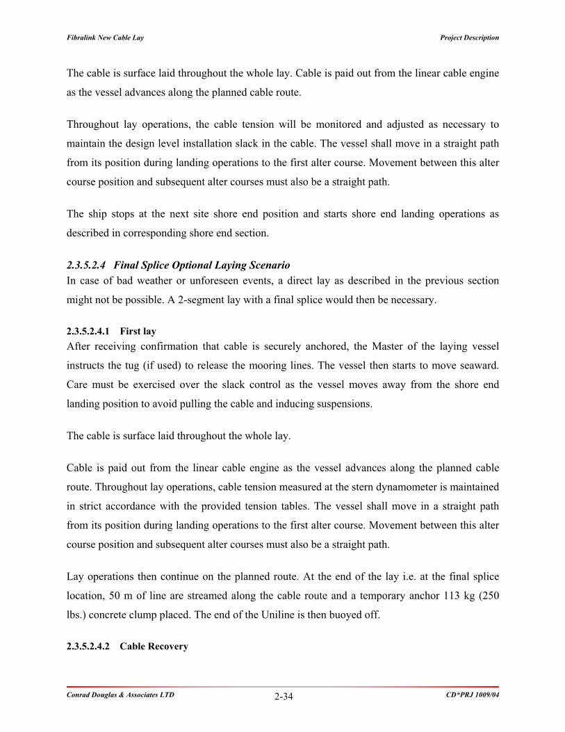
The cable is surface laid throughout the whole lay. Cable is paid out from the linear cable engine
as the vessel advances along the planned cable route.
Throughout lay operations, the cable tension will be monitored and adjusted as necessary to
maintain the design level installation slack in the cable. The vessel shall move in a straight path
from its position during landing operations to the first alter course. Movement between this alter
course position and subsequent alter courses must also be a straight path.
The ship stops at the next site shore end position and starts shore end landing operations as
described in corresponding shore end section.
2.3.5.2.4 Final Splice Optional Laying Scenario
In case of bad weather or unforeseen events, a direct lay as described in the previous section
might not be possible. A 2-segment lay with a final splice would then be necessary.
2.3.5.2.4.1 First lay
After receiving confirmation that cable is securely anchored, the Master of the laying vessel
instructs the tug (if used) to release the mooring lines. The vessel then starts to move seaward.
Care must be exercised over the slack control as the vessel moves away from the shore end
landing position to avoid pulling the cable and inducing suspensions.
The cable is surface laid throughout the whole lay.
Cable is paid out from the linear cable engine as the vessel advances along the planned cable
route. Throughout lay operations, cable tension measured at the stern dynamometer is maintained
in strict accordance with the provided tension tables. The vessel shall move in a straight path
from its position during landing operations to the first alter course. Movement between this alter
course position and subsequent alter courses must also be a straight path.
Lay operations then continue on the planned route. At the end of the lay i.e. at the final splice
location, 50 m of line are streamed along the cable route and a temporary anchor 113 kg (250
lbs.) concrete clump placed. The end of the Uniline is then buoyed off.
2.3.5.2.4.2 Cable Recovery

Fibralink New Cable Lay Project Description
Conrad Douglas & Associates LTD CD*PRJ 1009/04 2-35
While proceeding to the buoy position, all required deck equipment, (i.e., hack lines, recovery
line, lashing & stoppers) is staged as required.
Cable splicing equipment are broken out and tested prior to recovery of the cable.
Cable end buoy is recovered.
When the Uniline begins to take a lead to the cable end, the vessel begins moving to the cable
end as the rope is recovered.
The vessel proceeds in this manner until a sufficient amount of the laid cable is onboard to
perform the splice.
2.3.5.2.4.3 Final Splice
End of both cables is fed into the splicing area.
Splicing personnel proceed with the final splice.
The fibres are terminated and tested.
When the final splice is completed and the tests show no fault, the cable is out board. The system
should be tested when touching the seabed, before cutting the lowering line.
2.3.6 Cable Repair Techniques
The following section briefly touches on cable maintenance and repair. All submarine cables are
susceptible to failure from external sources, such as fishing activity and anchor mauls. The
following table gives the percentage of failure causes for 380 reported cable faults. Careful
planning and implementation can greatly reduce the risk of such failures. Initial prevention will
result in a highly reliable telecommunications facility.
Table 2-3: Percentage of Failure Causes for 380 Reported Cable Faults
Cause Count %
Abrasion 18 4.7%
Anchor 49 12.9%
Branching Unit 2 0.5%

Fibralink New Cable Lay Project Description
Conrad Douglas & Associates LTD CD*PRJ 1009/04 2-36
Cause Count %
Cable or Survey Ship Activity 5 1.3%
Dredging/Drilling and Pipe Installation 12 3.2%
Earthquake or Seabed Movement 10 2.6%
Equaliser 1 0.3%
Fatigue 1 0.3%
Fishing Activity 184 48.4%
Impact by Hard Object 5 1.3%
Insulation Failure 3 0.8%
Jointing Box 5 1.3%
Manufacturing Defect Cable 4 1.1%
Repeater 17 4.5%
Unknown Cable Deliberately Cut 1 0.3%
Unknown Cable Mauled 6 1.6%
Unknown Cable not repaired 1 0.3%
Unknown Fibre Attenuation 5 1.3%
Unknown Kinks, Twists, Loops 9 2.4%
Unknown Shunt Fault 31 8.2%
Unknown Tension Break 11 2.9%
TOTAL 380
2.3.6.1 Canvassing Offshore Industries
Fibralink will make strong representations to the governments to have the cable route declared a
prohibited anchorage.
If bottom fishing abounds in the vicinity of the route, it will be appropriate to establish a program
of liaison and dialogue with the industry. Hydrographic charts could be personalized to highlight
the route and carry suitable warnings and be distributed free with other promotional items.
2.3.6.2 Repair Methodology
When a cable system is interrupted, tests are made from terminals or suitable access points
ashore to localize the trouble to an accurate geographical position, as derived from laying
records. This localization will dictate the repair method to be selected, as follows:
Fibralink New Cable Lay Project Description
Conrad Douglas & Associates LTD CD*PRJ 1009/04 2-37
2.3.6.2.1 In Diver-Depths
When the interruption is close inshore (preferably less than 20 m), a barge can be mobilized and
moored over the site. Diving inspection or an electronic probe will locate the damaged area.
In the case of an electronic probe, a low frequency tone (e.g. 25 Hz) is injected on the centre
conductor from the terminal. The probe in its various forms is deployed close to the cable. This
will detect either the electromagnetic or electrostatic field developed along the cable. The range
of the signal decreases with the length from the terminal but should cause no problems in this
case. Probes can be a diver hand held device or attached to a two conductor cable towed from a
surface vessel (towed electroding).
This technique permits accurate location of the cable and further, will usually indicate the fault
location by registering a significant change in signal field strength at that point.
The ends will be hauled (or floated) to the surface and secured at the barge. After suitable
electrical/optical tests have confirmed no other interruptions are present, a new spare piece is
jointed/spliced in and the bight lowered, under controlled conditions, to the seabed. If
appropriate the exposed cable will be diver-jetted into the seabed.
2.3.6.2.2 Conventional Method in Deep Water
The assigned repair vessel travels to the location and, if appropriate, establishes the precise
position of the interruption by means of electroding. The vessel then using a special de-trenching
grapnel, grapples across the cable and raises it to the surface. The bight of cable is hauled
inboard on the grapnel and secured. After cutting the bight, the ends are opened and tested. In the
ideal case testing in one direction will establish its mechanical/transmission integrity while
testing in the other direction will indicate the break to be close to the ship.
After sealing and buoying off the good end, the short stray end is recovered to a spare storage
tank or coil space and the ship proceeds to grapple for the end on the far side of the break. She
raises the bight of cable, boards it, cuts the bight and tests. If everything is satisfactory she then
splices on replacement cable, from a storage tank or coil on board, to the good end and pays this
down to the seabed while steaming towards the buoyed end.

Fibralink New Cable Lay Project Description
Conrad Douglas & Associates LTD CD*PRJ 1009/04 2-38
When the cable buoy has been recovered and the first good end tested and confirmed to be still
OK the payout is terminated and the replacement cable is cut on the foredeck. Its end is joined to
the recovered end and a final splice is made, whereupon the bight of cable is lowered to the
seabed. After appropriate transmission tests have been made, the system can be returned to
traffic.
Mobilization would comprise loading the replacement cable, gathering such customer specialists
and equipment as are required and proceeding to site. The first alternative to a dedicated cable
ship as above would be to engage an offshore flatback on spot-charter, if available, and spend
some days fitting out and mobilizing as above for the repair. Then proceed to site.
2.3.6.3 Spare Cable and Repair Facilities
Spare cable and repair plant will be located as close to the cable route as possible, or at the base
of the dedicated cable ship or ship of opportunity. Spare cable will be stored in a sheltered,
temperature-controlled environment and be readily available for loading to ship at a deep-water
berth.
2.3.7 Waste Streams
This project has minimal waste being generated. The primary waste streams are:
1. Cable Station – construction waste
2. Nearshore manhole – minimal soil removal
3. Undersea Nearshore duct – Drill waste
All identified waste stream will contain non-toxic material that are currently being disposed of in
landfills in Jamaica. Where practicable, Fibralink will employ recycling techniques to limit the
nature of the waste such as the use of soil material in reinstatement of roadways.

Fibralink New Cable Lay Policy, 2BLegislative and Regulatory Framework
Conrad Douglas & Associates LTD CD*PRJ 1056/07
POLICY, LEGISLATION AND
REGULATORY FRAMEWORK

Fibralink New Cable Lay Policy, 2BLegislative and Regulatory Framework
Conrad Douglas & Associates LTD CD*PRJ 1056/07 3-1
3 Legislative and Regulatory Framework
3.1 Introduction
The policies, legislation, regulations and environmental standards of the Government of Jamaica
(GOJ), which pertains to this development have been researched and analysed, to ensure that the
project complies with all policy, legal and regulatory requirements. The areas examined included
environmental quality, health and safety, protection of sensitive areas, protection of endangered
species, site selection and land-use control at the regional, national and local levels, which relate
to or should be considered within the framework of the project (Table 3-1).
Table 3-1: Summary of the Applicable Legislation and the Responsible Agencies
LEGISLATION INSTITUTION RESPONSIBLE
Natural Resources Conservation Authority Act,
1991
Natural Resources Conservation
Authority/National Environment and Planning
Agency
Wildlife Protection Act, 1945
Natural Resources Conservation
Authority/National Environment and Planning
Agency
Beach Control Act, 1956
Natural Resources Conservation
Authority/National Environment and Planning
Agency
Town & Country Planning Act, 1987 Town Planning Department
Jamaica National Heritage Trust Act, 1985 Jamaica National Heritage Trust
Public Health Act, 1985Ministry of Health [Environmental Control
Division]
National Solid Waste Management Authority
Act, 2001National Solid Waste Management Authority
St. Thomas Development Order Town Planning Department

Fibralink New Cable Lay Policy, 2BLegislative and Regulatory Framework
Conrad Douglas & Associates LTD CD*PRJ 1056/07 3-2
3.2 National Policies
3.3 Applicable Legislation
3.3.1 The Natural Resources Conservation Authority Act, 1991
The NRCA Act addresses the designation of National Parks and Protected areas, and their
development. It is also concerned with
Designation of national park, protected area, etc
5.- (1) The Minister may, on the recommendation of the Authority after consultation with the
Jamaica National Heritage Trust, by order published in the Gazette designate-
a. any area of land as a national park to be maintained for the benefit of the public;
b. any area of land or water as a protected area in which may be preserved any
object (whether animate or inanimate) or unusual combination of elements of the
natural environment that is of aesthetic, educational, historical or scientific
interest; or
c. any area of land lying under tidal water and adjacent to such land or any area of
water as a marine park.
(2) The Authority shall cause any order made under subsection (1) to be published once in a
daily newspaper circulating in Jamaica.
Permit required
Section 9.-
(1) The Minister may, on the recommendation of the Authority, by order published in the
Gazette, prescribe the areas in Jamaica, and the description or category of enterprise,
construction or development to which the provisions of this section shall apply; and the
Authority shall cause any order so prescribed to be published once in a daily newspaper
circulating in Jamaica.

Fibralink New Cable Lay Policy, 2BLegislative and Regulatory Framework
Conrad Douglas & Associates LTD CD*PRJ 1056/07 3-3
(2) Subject to the provisions of this section and section 31, no person shall undertake in a
prescribed area any enterprise, construction or development of a prescribed description or
category except under and in accordance with a permit issued by the Authority.
(3) Any person who proposes to undertake in a prescribed area any enterprise, construction
or development of a prescribed description or category shall, before commencing such
enterprise, construction or development, apply in the prescribed form and manner to the
Authority for a permit, and such application shall be accompanied by the prescribed fee
and such information or documents as the Authority may require.
(5) In considering an application made under subsection (3) the Authority-
a. shall consult with any agency or department of Government exercising functions in
connection with the environment; and
b. shall have regard to all material considerations including the nature of the enterprise,
construction or development and the effect which it will or is likely to have on the
environment generally, and in particular on any natural resources in the area
concerned and the Authority shall not grant a permit if it is satisfied that any activity
connected with the enterprise, construction or development to which the application
relates is or is likely to be injurious to public health or to any natural resources.
(6) The Authority may-
a. grant a permit subject to such terms and conditions as it thinks fit; or
b. refuse to grant a permit, and where the Authority refuses to grant a licence it shall
state in writing the reasons for its decision and inform the applicant of his right under
section 35 to appeal against the decision.
(7) Any person who contravenes any provisions of subsection (2) shall be guilty of an
offence and shall be liable on summary conviction before a Resident Magistrate to a fine
not exceeding fifty thousand dollars or to imprisonment for a term not exceeding two
years or to both such fine and imprisonment, and-
a. where a person defaults in the payment of a fine imposed under this subsection, he
shall be liable to imprisonment for a term not exceeding one year; and

Fibralink New Cable Lay Policy, 2BLegislative and Regulatory Framework
Conrad Douglas & Associates LTD CD*PRJ 1056/07 3-4
b. where the offence is a continuing offence, he shall be liable to a further fine not
exceeding three thousand dollars for each day on which the offence continues after
conviction.
Power of Authority to request Marine Assessment, etc
Section 10.-
(1) Subject to the provisions of this section, the Authority may by notice in writing require an
applicant for a permit or the person responsible for undertaking in a prescribed area, any
enterprise, construction or development of a prescribed description or category-
a. to furnish to the Authority such documents or information as the Authority thinks
fit, or
b. where it is of the opinion that the activities of such enterprise, construction or
development are having or are likely to have an adverse effect on the
environment, to submit to the Authority in respect of the enterprise, construction
or development, an Marine Assessment containing such information as may be
prescribed, and the applicant or, as the case may be, the person responsible shall
comply with the requirement.
(2) A notice issued pursuant to subsection (1) shall state the period within which the
documents, information or assessment, as the case may be, shall be submitted to the
Authority.
(3) Where the Authority issues a notice under subsection (1), it shall inform any agency or
department of Government having responsibility for the issue of any licence, permit,
approval or consent in connection with any matter affecting the environment that a notice
has been issued, and such agency or department shall not grant such licence, permit,
approval or consent as aforesaid unless it has been notified by the Authority that the
notice has been complied with and that the Authority has issued or intends to issue a
permit.
(4) Any person who, not being an applicant for a permit, refuses or fails to submit an Marine
Assessment as required by the Authority shall be guilty of an offence and shall be liable

Fibralink New Cable Lay Policy, 2BLegislative and Regulatory Framework
Conrad Douglas & Associates LTD CD*PRJ 1056/07 3-5
on summary conviction before a Resident Magistrate to a fine not exceeding thirty
thousand dollars.
Revocation of permit
Section 11.-
(1) Subject to subsection (2), the Authority may by notice addressed to the person to whom a
permit was issued revoke or suspend the permit if it is satisfied that there has been a
breach of any term or condition subject to which the permit was granted, or if such
person fails or neglects to submit to the Authority, in accordance with section 10, any
documents, information or assessment required thereunder.
(2) Except as provided in subsection (3), the Authority shall, before revoking a permit, serve
on the person to whom it was granted a notice in writing-
a. specifying the breach or default on which the Authority relies and requiring him
to remedy it within such time as may be specified in the notice, and
b. informing him that he may apply to the Authority to be heard on the matter within
such time as may be specified in the notice.
(3) The Authority shall not be obliged to serve a notice pursuant to subsection (2) in relation
to any breach if a cessation order pursuant to section 13 or an enforcement notice
pursuant to section 18 is in effect in relation to that breach.
Cessation order
13.-
(1) Without prejudice to the provisions of section 9 (7), 10 (4),11 and 12 (3)-
a. where a person fails to comply with the provisions of section 9 (2); or
b. where the person responsible fails to submit an Marine Assessment within the
time specified by the Authority; or
c. where a person fails to comply with the provisions of section 12 (1),the Authority
may issue an order in writing to such person directing him to cease, by such date

Fibralink New Cable Lay Policy, 2BLegislative and Regulatory Framework
Conrad Douglas & Associates LTD CD*PRJ 1056/07 3-6
as shall be specified in the order, the activity in respect of which the permit,
licence or Marine Assessment, as the case may be, is required.
(2) Where the person to whom an order is issued under subsection (1), fails to comply with
the order, the Minister may take such steps as he considers appropriate to ensure the
cessation of the activity to which the order relates.
Where authorized by the Minister acting pursuant to subsection (2), a member of the Jamaica
Constabulary Force may use such force as may be necessary for the purpose of ensuring
compliance with an order referred to in that subsection; and any person who hinders or obstructs
any such member acting as aforesaid shall be guilty of an offence and shall be liable on summary
conviction before a Resident Magistrate to a fine not exceeding ten thousand dollars or to
imprisonment for a term not exceeding one year.
3.3.2 The Wildlife Protection Act, 1945
This act involves the declaration of game sanctuaries and reserves, game wardens, control of
fishing in rivers, protection of specified rare or endemic species.
The Act also provides for the protection of animals and makes it an offence to harm or kill a
species that is protected. It stipulates that, having in one’s possession “whole or any part of a
protected animal living or dead” is illegal.
This Act was consulted for the proposed project due to the possibility of such animals being
found on the proposed site or in the adjacent waters. In addition, under this Act, provision has
been made for the pollution of rivers, whereby it is an offence to discharge any substances into
any river, which may be harmful to fish.
3.3.3 The Beach Control Act, 1956
This act was passed in an effort to properly manage the coastal and marine resources of Jamaica.
This occurs through the necessary licensing of activities on the foreshore and the floor of the sea.
The Act also addresses access to the shoreline, fishing, public recreation, and the establishment
of marine protected areas.

Fibralink New Cable Lay Policy, 2BLegislative and Regulatory Framework
Conrad Douglas & Associates LTD CD*PRJ 1056/07 3-7
3.3.4 The Town and Country Planning Act
The Town and Country Planning Act covers the development and use of land. In accordance
with this law, the Town Planning Department is the Agency that reviews any plans involving
industrial development.
This law allows specific conditions to be stipulated and imposed on any approved plans. This
planning decision is based upon several factors including;
the location of the development
the nature of the industrial process to be carried out
the land use and zoning
the effect of the proposal on amenities and traffic among other things.
Applications to local planning authority for permission
11.-
(1) Subject to the provisions of this section and section 12, where application is made to a
local planning authority for permission to develop land, that authority may grant
permission either unconditionally or subject to such conditions as they think fit, or may
refuse permission; and in dealing with any such application the local planning authority
shall have regard to the provisions of the development order so far as material thereto,
and to any other material considerations.
(1) (A) where the provisions of section 9 of the Natural Resources Conservation Authority
Act apply in respect of a development which is the subject of an application under
subsection (1), planning permission shall not be granted unless-
a. an application to the Natural Resources Conservation Authority has been made as
required by such provisions as aforesaid; and
b. that Authority has granted or has signified in writing its intention to grant, a
permit under that Act.
(2) Without prejudice to the generality of subsection (1), conditions may be imposed on the
grant of permission to develop land thereunder-

Fibralink New Cable Lay Policy, 2BLegislative and Regulatory Framework
Conrad Douglas & Associates LTD CD*PRJ 1056/07 3-8
for regulating the development or use of any land under the control of the
applicant (whether or not it is land in respect of which the application was made)
or requiring the carrying out of works on such land, so far as appears to the local
planning authority to be expedient for the purposes of or in connection with the
development authorized by the permission;
(3) Provision may be made by a development order for regulating the manner in which
applications for permission to develop land are to be dealt with by local planning
authorities, and in particular
a. for enabling the Minister to give directions restricting the grant of permission by
the local planning authority, during such period as may be specified in the
directions in respect of any such development, or in respect of development of
any such class, as may be so specified
b. for authorizing the local planning authority, in such cases and subject to such
conditions as may be prescribed by the order, or by directions given by the
Minister thereunder, to grant permission for development which does not appear
to be provided for in the order or in any plan or statement deposited with the order
and is not in conflict therewith;
c. for requiring the local planning authority, before granting or refusing permission
for any development, to consult with such authorities or persons as may be
prescribed by the order or by directions given by the Minister thereunder;
d. for requiring the local planning authority to give to any applicant for permission,
within such time as may be prescribed by the order such notice as may be so
prescribed as to the manner in which his application has been dealt with;
e. for requiring the local planning authority to furnish to the Minister and to such
other Persons as may be prescribed by or under the order, such information as
may be so prescribed with respect to any application for permission made to them,
including information as to the manner in which such application has been dealt
with.
f. Every local planning authority shall keep, in such manner as may be prescribed by
the development order a register containing such information as may be so

Fibralink New Cable Lay Policy, 2BLegislative and Regulatory Framework
Conrad Douglas & Associates LTD CD*PRJ 1056/07 3-9
prescribed with respect to applications for permission made to such authority,
including information as to the manner in which such applications have been dealt
with; and every such register shall be available for inspection by the public at all
reasonable hours.
Applications to determine whether permission required
14.-
(1) If any person who proposes to carry out any operations on land or make any change in
the use of land wishes to have it determined whether the carrying out of those operations
or the making of that change in the use of the land would constitute or involve
development of the land within the meaning of this Act, and, if so, whether an application
for permission in respect thereof is required under this Part having regard to the
provisions of the development order, he may, either as part of an application for such
permission, or without any such application, apply to the local planning authority to
determine that question.
(2) The foregoing provisions of this Part shall, subject to any necessary modifications, apply
in relation to any application under this section and to the determination thereof as they
apply in relation to applications for permission to develop land and to the determination
of such applications.
3.3.5 The Public Health Act, 1985
This Act falls under the ambit of the Ministry of Health (MOH) and governs all matters
concerning the handling of food material. In addition, provisions are also made under this Act for
the activities of the environmental control division (ECD), a division of the MOH. The ECD’s
functions include:
The monitoring of waste water quality,
Monitoring of occupational health as it relates to industrial hygiene of potentially
hazardous working environments
This Act has been consulted for the proposed cable lay.

Fibralink New Cable Lay Policy, 2BLegislative and Regulatory Framework
Conrad Douglas & Associates LTD CD*PRJ 1056/07 3-10
3.3.6 The Jamaica National Heritage Trust Act, 1985
The Jamaica National Heritage Trust, formerly the Jamaica National trust, administers the Act.
This Act provides for the protection of important areas, including the numerous monuments,
forts, statues, and buildings of historic and architectural importance in Jamaica.
This Act will prove applicable if any structures of archaeological and/or architectural importance
are located on the site, affected by the site activities or unearthed during site activities. Since this
project is in an area that may contain items of archaeological importance, an Archaeological
Retrieval Plan is included as part of this document.
3.3.7 The National Solid Waste Management Authority Act, 2001
The National Solid Waste Management Authority (NSWMA) under this Act has the
responsibility to manage and regulate the solid waste sector. It includes requirements for licences
for operators and owners of solid waste disposal facilities (in addition to permit requirements of
NEPA).
Fibralink will utilise existing, approved industrial landfill sites for all solid waste generated from
this proposed project. Fibralink will also practice recycling as much as possible of the materials
used within its operation.
3.3.8 Draft National Building Code for Jamaica, 2007
The decision to review and revise Jamaica's building codes, which has taken almost four years,
was in keeping with the guiding principles for the development of standards as enshrined in the
World Trade Organisation's Technical Barriers to Trade Regulations and Annex dealing with the
Code of Good Practice for the Development of standards.
These principles speak to use of international standards as the basis for developing national
standards, require the inclusion of all interested parties and partners in the standards development
process; demand that this process be carried out with openness and transparency at all stages of
development and that the final documents be approved on the basis of consensus. This document
is still in the draft stage.

Fibralink New Cable Lay Policy, 2BLegislative and Regulatory Framework
Conrad Douglas & Associates LTD CD*PRJ 1056/07 3-11
Jamaica currently uses the codes based on the International Building Code (IBC) published by
the International Code Council (ICC) USA since 2000, which is currently being used by various
other countries in the English-speaking Caribbean.
These standards will be governed under the Town and Country Planning Act and be regulated by
the Parish Councils.
This project will conform to all applicable building codes as mandated by the Parish Council and
other relevant agencies.
3.3.9 St. Thomas Parish Development Plan,
There are no development plans currently in effect for the Parish of St. Thomas. The St. Thomas
Parish Council is currently planning to develop a development order to ensure the future
development of the parish1. Development of the Parish is currently through the Parish
Development Committees.
3.4 International Policy
3.4.1 Agenda 21
Jamaica is signatory to the convention (Agenda 21) which came out of a United Nations hosted
conference on the Environment and Development, held in Rio de Janeiro in June 1992 (EARTH
SUMIT ’92). Twenty-seven (27) environmental principles were outlined. Not all these
principles are applicable to the project, but those deemed relevant and appropriate are outlined
below:
Principle 1 Human beings are at the centre of concerns for sustainable development.
They are entitled to a healthy and productive life in harmony with nature.
Principle 3 The right to development must be fulfilled to equitably meet developmental
and environmental needs of present and future generations.
1 http://www.jamaica-gleaner.com/gleaner/20070204/lead/lead5.html

Fibralink New Cable Lay Policy, 2BLegislative and Regulatory Framework
Conrad Douglas & Associates LTD CD*PRJ 1056/07 3-12
Principle 4 In order to achieve sustainable development, environmental protection shall
constitute an integral part of the development process and cannot be considered in
isolation from it.
Principle 10 Environmental issues are best handled with the participation of all
concerned citizens, at the relevant level, each individual shall have appropriate access to
information concerning the environment that is held by public authorities, including
information on hazardous materials and activities in their communities, and the
opportunity to participate in decision-making processes. States shall facilitate and
encourage public awareness and participation by making information widely available.
Effective access to judicial and administrative proceedings, including redress and
remedy, shall be provided.
Principle 11 States shall enact effective environmental legislation, Environmental
Standards, management objectives and priorities should reflect the environmental and
developments context to which they apply.
Principle 15 In order to protect the environment, the precautionary approach shall be
widely applied by States according to their capabilities. Where there are threats of
serious or irreversible damage, lack of full scientific certainty shall not be used as a
reason for postponing cost-effective measures to prevent environmental degradation.

Fibralink New Cable Lay 3BAnalysis of Alternatives
Conrad Douglas & Associates LTD CD*PRJ 1056/07
ANALYSIS OF ALTERNATIVES

Fibralink New Cable Lay 3BAnalysis of Alternatives
Conrad Douglas & Associates LTD CD*PRJ 1056/07 4-1
4 Analysis of Alternatives
4.1 Introduction
4.2 No-Action Alternative
The proposed submarine fibre-optic cable would not be installed. No operations and maintenance
activities would occur. This alternative would not fulfil the purpose of the project or meet the
identified needs for high-speed data transmission in the eastern section of Jamaica. The
redundant capabilities of the system would not be put in place which would result in loss of
service should the existing system be damaged. Also, Jamaica would not realise the potential
connection to South America which has become a major trading partner. The enormous
economic and social development opportunities for Information Communication Technology
(ICT) as well as the investment will be lost, including the potential for job creation. It therefore
would be necessary to consider alternative methods of meeting data transmission requirements.
4.3 Landing Site Alternatives
The proponent also considered a number of alternate landing sites along the South-east coasts of
the island. The landing sites were selected based on a number of factors. Of primary concern was
the type and degree of impact the cable installation would have on the coastal and marine
ecology. The sites that are proposed in this report represent the best selections from exhaustive
considerations of a number of sites. Some of which were disqualified on the basis of:
Estimated coastal and marine ecological impacts,
Distance to existing or proposed hubs,
Impacts to and on cable laying installation, and
Through consultations.
4.3.1 Bull Bay, St Andrew Alternatives
The new landing site to offer redundant capabilities was chosen within the immediate region of
the existing landing. The coastline within the 1 km - 4 km distance to the east of the Bull Bay
landing was considered ideal for the new landing site. West of the exsiting landing site would
propose landing with the Port Royal Protected Area. This direction was rejected on this basis.

Fibralink New Cable Lay 3BAnalysis of Alternatives
Conrad Douglas & Associates LTD CD*PRJ 1056/07 4-2
The areas targeted were those where the main road was relatively close to the shoreline and in
organized developments with fishing activity limited to small boat (canoe type) boats with nets,
trawl and spear fishing and little or no apparent vessel anchoring.
The two areas evaluated are as follows:
1. Copacabana; 17° 56.571’N, 076° 41.478’W
2. New Little Copa Club; 17° 56.553’N, 076° 41.379’W – Preferred Alternative
The New Little Copa Club landing site in Bull Bay is within reach of the existing cable landing
site with the necessary infrastructure already in place (cable housing building), with well defined
ownership and property details.
The other site considered within the immediate region was Copacabana, approximately 1.6 km
east of the existing Fibralink cable station. Both sites share a coarse sand beach that deepens
slowly without any reefs present. It is similar to the existing Bull Bay approach which is mainly
coarse sand and small boulders without any coral present. Both these sites provide excellent
access for shore end activities.
The distance from the main road, along the community roads, to the proposed Nearshore
manhole is approximately 230 m, a longer distance in comparison to the New Little Copa Club
site which is 75 m. The elevation is approximately 3 m compared to New Little Copa Club which
is at 4.5 m above sea level. However, the proposed manhole location is an area that has been
designated as a community park. Also, the New Little Copa Club site has lower backhaul costs.
4.3.2 Prospect - Morant Point, St Thomas Alternatives
The coastline along this area has primarily shallow water less than 6 m water depth to a distance
from the shoreline varying from approximately 50 m – 300 m with breaking waves on the
seaward side where the depth appears to increase dramatically. This is indicative of coral reefs in
the area of the breaking waves for the area and was confirmed through dive surveys. However,
the charts indicated a deeper water channel between these reefs at Morant Point, the bottom of
which was found to consist mainly of sand.

Fibralink New Cable Lay 3BAnalysis of Alternatives
Conrad Douglas & Associates LTD CD*PRJ 1056/07 4-3
This entire area is within a developing community, Prospect, which can be described as
organized middle/low income, with fishing activity limited to small boat (canoe type) boats with
nets, trawl and spear fishing and little or no apparent vessel anchoring.
There were three areas that were closely evaluated:
1. Ocean View Close; 17° 51.865’N, 076° 20.450’W – The Preferred Alternative
2. Windy Way; 17° 51.818’N, 076° 20.403’W
3. Tuna Drive; 17° 51.610’N, 076° 20.346’W
All sites provide excellent access for shore end activities.
Windy Way and Tuna Drive have rugged coral shorelines unlike Ocean View Close which has a
sandy shore and a gentle slope from shore to the channel. The water depth at the shoreline is
approximately 1.2 m for a distance of approximately 10 m for all three sites where it drops into
the sandy channel noted above except for Tuna Drive. The manhole location for all three sites is
approximately 1.5 m above sea level and 10 m from the shoreline. The distance to the proposed
cable station site is 820 m for Windy Way, 600 m for Ocean View Close and 1.4 km for Tuna
Drive. Windy Way requires a direction bore of approximately 150 m – 180 m, less than that for
Ocean View Close, with Tuna Drive requiring more. The right-of-way option for Ocean View
Close provided better solutions for the project. Also, the channel at Ocean View Close provides
some protection against heavy seas from the south which is not offered by the other sites.
4.4 Technology Alternatives
The proponent evaluated a number of technological alternatives that either did not fulfill the
purpose of the project or did not meet agreed criteria. The major factors that affected the
acceptability of those options were potentially adverse environmental effects and problems
related to technical feasibility. The following details the advantages of incorporating a high
speed data fibre-optic cable in Jamaica, when compared with other technologies outlined below:
SPEED: Fibre optic networks operate at high speeds - up into the gigabits
BANDWIDTH: large carrying capacity

Fibralink New Cable Lay 3BAnalysis of Alternatives
Conrad Douglas & Associates LTD CD*PRJ 1056/07 4-4
DISTANCE: Signals can be transmitted further without needing to be "refreshed" or
strengthened.
RESISTANCE: Greater resistance to electromagnetic noise such as radios, motors or
other nearby cables.
MAINTENANCE: Fibre optic cables costs much less to maintain.
4.4.1 Radio
Other high-speed wireless providers, such as those using 24 GHz, 28 GHz and 38 GHz spectrum,
have concentrated on the more densely populated urban areas because of transmission distance
limitations. Signals using these radio frequencies are generally limited to a one to three-mile
radius, or three to 28 square miles, which makes application in less densely populated areas less
economical. These frequencies are inherently more susceptible to weather and environmental
interference.
4.4.2 Telephony
The telephone industry predominantly uses copper twisted-pair for the delivery of
communications services to commercial and residential customers. Plain old telephone systems
have been the primary means of communicating both locally and long distance. The problem is
that it was designed for the transmission of voice communications. It's a mature technology, but
inadequate by design, the amount of bandwidth that can be delivered is restricted by the
characteristics of the copper twisted-pairs installed between the customer and central office.
Fibre-optics spans the long distances between local phone systems as well as providing the
backbone for many network systems (such as cable television services, university campuses,
office buildings, industrial plants, and electric utility companies).
The main difference is that fibre-optics use light pulses to transmit information down fibre lines
instead of using electronic pulses to transmit information down copper lines.
Services such as DSL delivered across a local exchange carrier’s existing copper wire system are
capable of delivering very high speeds. However, DSL suffers performance limitations based on
the distance from the customer premises to the serving central office. Distances are limited to
about four to five miles from a central office for the lowest speed solutions and 10,000 feet or
Fibralink New Cable Lay 3BAnalysis of Alternatives
Conrad Douglas & Associates LTD CD*PRJ 1056/07 4-5
less for the fastest. Additionally, much of the plant is physically incapable of providing
broadband service.
4.4.3 Satellite Data Transmission
The proponent evaluated a non-cable option of replacing the proposed telecommunication and
data transmission services with satellite communications. The use of communications satellites
to provide the services identified as necessary would require no construction in the marine
environment, but would not provide the capacity or quality of service proposed under the project.
Satellite networks, such as direct broadcast satellite, currently offer only one-way Internet
access. Upstream access is limited to existing copper telephone lines. Other alternatives like Low
Earth Orbit (LEO) Satellite Systems are not scheduled to be completed for years and have not
proven capable of providing "carrier-class" voice or data services. Fibre optic cables transmit
voice and data traffic with higher reliability and security at a cheaper rate than satellite. While a
satellite call must travel 27,000 miles (35,780 km) from the earth to the satellite and then another
27,000 miles back, a Jamaica to Florida fibre optic call need only travel about 200 miles point-
to-point. At the speed of light this helps to eliminate the delays suffered during a satellite
telephone call.
The option does not meet the purpose of the project.

Fibralink New Cable Lay 4BDescription of the Environment
Conrad Douglas & Associates LTD CD*PRJ 1009/04
DESCRIPTION OF THE ENVIRONMENT

Fibralink New Cable Lay 4BDescription of the Environment
Conrad Douglas & Associates LTD CD*PRJ 1009/04 5-1
5 Description of the Environment
5.1 Physical Environment
5.1.1 Meteorology
While there are variations in the weather patterns along the south coasts of the island, it is not
envisioned that any of the parameters assessed in this section will have any negative impacts on
the establishment, operation or maintenance of the project.
Ideally, one should obtain data for weather and meteorological parameters from stations within
the defined boundaries of the region in which an assessment is being made. The following sub-
sections outlines the parameters used for assessment:
5.1.1.1 Climate
5.1.1.2 Rainfall
The project area is located along the south-eastern coast of Jamaica, which is characterized by
low and/or sporadic rainfall patterns during the course of the year. This region is shielded by the
John Crow Mountain and Blue Mountain ranges from the North-easterly trade winds which enter
the island. This shielding effect results in the rapid condensation of the wind currents as they
come off the mountain ranges, causing reduced precipitation as they flow into the Southern part
of the island. This causes the above stated low and/or sporadic rainfall with not much overcast
conditions being experienced.
Typical of coastal regions is the effect of land and sea breeze, in which there is an expected
gentle moist breeze coming on-land from the sea during the course of the day, and a gentle
breeze flowing off-land to the sea during the night time. This event is a characteristic of the
thermal properties of both the land and the sea and would not significantly affect weather in a
general way.
The nature of this project, from construction through to operation dictates that the weather
regime experienced in this area, will not have any impact on this project.
Figure 5-1 and Figure 5-2 below shows the average annual rainfall figures for the Palisadoes and
Morant point. These represent the closest available data points provided by the Meteorological

Fibralink New Cable Lay 4BDescription of the Environment
Conrad Douglas & Associates LTD CD*PRJ 1009/04 5-2
Office of Jamaica. Bull Bay experiences less than 150 mm of rainfall annually, whereas Prospect
experiences less than 270 mm of rainfall per year.
Average Annual Rainfall (mm) for the Palisadoes, St.
Andrew, for the Period 2000 2006
0
20
40
60
80
100
120
140
160
2000 2001 2002 2003 2004 2005 2006
Year
AverageAnnualRainfall
(mm)
Figure 5-1: Average Annual Rainfall for the Palisadoes, St. Andrew, 2000-2006
Average Annual Rainfall (mm) for Morant Point, St.
Thomas, for the Period 2000 2006
0.00
50.00
100.00
150.00
200.00
250.00
300.00
2000 2001 2002 2003 2004 2005 2006
Year
AverageAnnualRainfall
(mm)
Figure 5-2: Average Annual Rainfall for Morant Point, St. Thomas, 2000-2006
5.1.1.3 Wind
The daily wind pattern across Jamaica is dominated by the Northeast Trade Winds. During the
day on the South Coast, the sea breeze combines with the Trades to give an east-southeasterly
wind with an average speed of 18 knots (21 miles per hour). In the period December to March,
however, the Trades are lowest and the local wind regime is a combination of trades, sea breeze,

Fibralink New Cable Lay 4BDescription of the Environment
Conrad Douglas & Associates LTD CD*PRJ 1009/04 5-3
and a northerly or northwesterly component associated with cold fronts and high-pressure areas
from the United States.
During the night, the trades combine with land breezes which blow offshore down the slopes of
the hills near the coasts. As a result, on the South Coast, nighttime winds generally have a
northerly component with a mean speed of 7 knots (8 miles per hour). By day, from June to July,
mean onshore winds often reach a maximum of up to 26 knots (30 miles per hour) along the
South Coast during mid-afternoon.
Average Yearly Wind Speed for The Period
2000 - 2006
13.5
14
14.5
15
15.5
2000
2001
2002
2003
2004
2005
2006
Year
Avera
ge W
ind
Sp
eed
(Km
/h)
Figure 5-3: Average Wind Speed per Year along the South-East coast of Jamaica, 2000-2006
5.1.1.4 Weather Impact on Project
While there are variations in the weather patterns between the north and south coasts of the
island, it is not envisioned that any of the parameters assessed in this section will have any
negative impacts on the establishment, operation or maintenance of the project.

Fibralink New Cable Lay 4BDescription of the Environment
Conrad Douglas & Associates LTD CD*PRJ 1009/04 5-4
5.1.2 Hydro- and Geophysical Environment
5.1.2.1 Geology
5.1.2.1.1 Bull Bay, St. Andrew
Elevations at the site increase gently from sea level along the shoreline to a maximum of 1.5
metres above sea level along the boundary with the Bull Bay to Kingston main road, in the
vicinity of Seven Miles. The area is underlain by alluvium terraces and the August Town
Formation. The river terraces are detritus from the Hope and other rivers that drain the area. The
August Town Formation is of Pliocene age and is the Lower Coastal Group and consists of
yellowish sandy marls and limestone rich in fossils.
The soil at the shoreline is dark silty-sand overlaid by coarse and smooth pebbles. The potential
for erosion of soil materials during periods of moderate to heavy rainfall at the site is minimal as
the area continuously undergoes strong wave action and is fairly stable.
Along the beach, the substrate depth ranged from 0 cm to 10 cm, and consists of coarse, angular,
highly sorted carbonate sand grains with large pieces of coralline material along with the
numerous varied sized pebbles. This suggests recent (less than 50 years) storm surge deposits
(possibly from Hurricane Ivan in September 2004). Sediments on the sandy shore are composed
of typical dark sand grains as seen on Jamaica’s south coast.
It is not perceived that the present topography and geology of the site requires any special
considerations prior to a development such as the one proposed being implemented.
The inshore has a relatively, consistent declining slope substrate of dark sand from near shoreline
to about 460 m offshore. The area is made-up of soft sandy substrate. There is no coral reef
substrate along the survey path or rocky outcroppings.
5.1.2.1.2 Prospect, St. Thomas
Elevations at the site increase gently from sea level along the shoreline to a maximum of 2
metres above sea level at the end of Ocean View Close. The community of Prospect (along the
Kingston to St. Thomas main road) the elevation is approximately 10 m. The Prospect area is
underlain by the coastal limestone of the White Limestone Group. The limestone patchily fringes
the coast and consists of soft marls. Thickness approaches 30 metres.

Fibralink New Cable Lay 4BDescription of the Environment
Conrad Douglas & Associates LTD CD*PRJ 1009/04 5-5
The soil at the shoreline is white sand with few smooth pebbles. The potential for erosion of soil
materials during periods of moderate to heavy rainfall at the site is minimal. The shoreline is
fairly stable due to the sheltered bay and the coral reef and seagrass beds that offer it protection.
The surrounding lands are vegetated and offer protection landwards.
Along the beach, the substrate depth ranged from 0 cm to 10 cm, and consists of sorted carbonate
sand grains with small pieces of coralline material. Sediments on the sandy shore are composed
of typical white sand grains.
It is not perceived that the present topography and geology of the site requires any special
considerations prior to a development such as the one proposed being implemented.
The inshore has a relatively, consistent declining slope substrate of white calcareous sand from
near shoreline to 1000 m offshore. The area is made-up of soft sandy substrate. Though a small
fringing coral reef is in close proximity, the route alignment proposed will not infringe on this
important ecosystem as it will be laid on the sandy channel bottom.
5.1.2.2 Hydrology
The formations are classified as aquicludes i.e. it does not transmit water and does not yield
water readily to wells and springs. There is no potential for water resources development at Bull
Bay.
The limestone is classified as an aquiclude i.e. it does not transmit water and does not yield water
readily to wells and springs. Wells drilled at Prospect by the National Water Commission
(NWC) were very low producers and have been abandoned. There is no potential for water
resources development at Prospect.
Figure 5-4 below outlines the hydrostratigraphic map of St. Thomas showing the two sites.

Fibralink New Cable Lay 4BDescription of the Environment
Conrad Douglas & Associates LTD CD*PRJ 1009/04 5-6
Site 2:
PROSPECT
Site1:
Bull Bay
Site 2:
PROSPECT
Site1:
Bull Bay
Figure 5-4: Hydrostratigraphic Map showing the two sites: Bull Bay and Prospect2
2 Extracted from the Hydrostratigraphy Map of Jamaica provided by The Water Resources Authority
(WRA), Jamaica

Fibralink New Cable Lay 4BDescription of the Environment
Conrad Douglas & Associates LTD CD*PRJ 1056/07 5-7
5.2 Hazard and Risk Assessment
The proposed project consists of two concurrent operational phases:
1. An offshore operational phase.
2. An onshore operational phase.
The components of both phases will set the baseline for the operation of the proposed cable
infrastructure, and therefore must be considered when estimating the vulnerability of the
proposed infrastructure to nature. The operational infrastructure has the potential to be affected,
to some degree, by existing climatic and potential weather patterns, geological activity
(specifically tectonic activity) and the hydrostratigraphy (especially in relation to flooding
potential) of the various regions where cable installation and laying is proposed to occur. For the
purposes of this Marine Assessment offshore consideration will be given only up to the boundary
of the Jamaican coastal waters – beyond that is beyond the jurisdiction of this assessment,
however, if necessary, references to any pertinent and appropriate similarities in the region will
be incorporated.
5.2.1 Offshore Cable Operations
The offshore cable operational phase is slated to occur in two distinct phases:
1. Deep-shore operations
2. Near shore operations (this is a transition into the onshore cable operational phase.)
Common to both phases is the medium of operation (water) and, as such, are likely to be affected
by wave action that is generated from aggressive deep water movement, which is caused by
storm surges and tectonic activity. Extreme occurrences of either of these events could cause
unlikely cable failure through abrasion and or instantaneous or gradual extension of the cable
beyond the elastic limits of its component materials. However, as with every event, there is a
threshold required for noticeable occurrence and also a limit at which the event will cause
unfavourable results; therefore, it is arbitrary to assume that any storm surge or tectonic activity
will cause any cable unlikely failure. Although there is no pragmatic way to define exactly what
level of displacement in the sea floor (vertical and horizontal) or what type of storm surge will
generate a certain definable stress on the cable, it is statistically possible to conclude from Table
2-3 that both abrasion and tectonic activity rarely causes cable failure. Implicit in the data, is the

Fibralink New Cable Lay 4BDescription of the Environment
Conrad Douglas & Associates LTD CD*PRJ 1056/07 5-8
fact that these events rarely generate the forces required to exceed the limits of the cable
materials’ strength. Therefore, one can assume that the combined material strength of the cable
materials have been designed to withstand common abrasion forces resulting from water
movement, and the effects of common minor plate movement. Keep in mind that there are miles
of this type of cable deployed worldwide under a wide variety of marine and seismic conditions
that are fully functional.
The deep shore aspect of the cable operations can be generally regarded as unaffected by storm
surges. Storm surges do not usually disturb the ocean bottom in deep waters by virtue of deep
water depth in relation to the volume of water that is displaced. However, pronounced effects are
estimated as likely for near-shore operations as the cable makes the transition to onshore
operations. However, as stated earlier, it is difficult to correlate storm surge magnitude with
sustainable cable integrity – one can only assume that cable breakage is unlikely to occur due to
the design and established track record of the industry. Cable breakage is unlikely in and of itself
to result in environmental degradation or negative environmental impacts.
5.2.2 Onshore Cable Operations
The onshore cable operation has two (2) distinct areas of operation:
1. Onshore shelter station where data relay is done
2. Terrestrial areas:
a. Above ground, along existing electrical high tension wires
b. Underground, on route to installation or relay areas
Given the degree and frequency of seismic activity in Jamaica (See Section 5.2.3 below), seismic
activity is not expected to generally affect either the terrestrial areas or the on-shore shelter
station area in a critical way. Further, it is assumed that existing infrastructure would have been
approved for construction with considerations being given to flooding vulnerability, land
slippage vulnerability and seismic activity. Hence, given the relationship between existing
infrastructure and the proposed cable network, the hazard vulnerability, in the above mentioned
regards, will depend largely on the approved infrastructure, in which the cable and associated
equipment are housed.

Fibralink New Cable Lay 4BDescription of the Environment
Conrad Douglas & Associates LTD CD*PRJ 1056/07 5-9
Of considerable concern is the potential effect of storm surge on the on-land shelter station
which houses the electronic equipment for data relay. Effects from flooding and battering due to
these storm surges could pose problems for both the electronic equipment and the building’s
structural integrity. Therefore, the building has been designed to be at a proposed height of more
than 3m above sea level, which is estimated to give it sufficient clearance from storm surge
activity. Regardless, the terrain of the sites is estimated to substantially exceed this proposed
minimum requirement. It is not anticipated that even if the buildings and equipment were to be
damaged by natural hazards that it would result in a negative environmental impact.
5.2.3 Seismic Vulnerability
Jamaica lies in the seismically active northern plate boundary zone of the Caribbean Plate
(Draper et al., 1994 and Figure 5-5). High magnitude earthquakes originating from as far away as
the south coast of Cuba may be felt in Jamaica. For example the Cabo Cruz earthquake of
magnitude 6.9 which occurred in May 1992 was felt with intensity 4 in Kingston, Jamaica. The
1993 earthquake of magnitude 5.4 which originated in Jamaica was felt in Cuba with intensities
of 3-4. No damage was reported in either case from the distant country (pers. comm. M.
Grandison).
Figure 5-5: Tectonic Plates in the Caribbean region

Fibralink New Cable Lay 4BDescription of the Environment
Conrad Douglas & Associates LTD CD*PRJ 1056/07 5-10
Figure 5-6 shows the epicentres of over one-hundred (100) earthquakes which have occurred in
or near Jamaica between 1998 and 2001. With over 100 such occurrences, there was no
significant damage to any approved infrastructure within the island to warrant consideration for
the adjustment or revision of any building or construction codes for the island.
Figure 5-6: Epicentres of Earthquakes Occurring Between 1998 and 2001 In The Vicinity Of Jamaica3
Figure 5-7, Figure 5-8, and Figure 5-9 are summarized in Table 5-1 in relation to the proposed
coastal landing sites. Table 5-2 allows one to conceptualize the type of effect the predicted
values in Table 5-1 are likely to have. In analyzing Table 5-1, it becomes evident the most
seismically active of all three sites is that of the Bull Bay site. As such, this site may be used as
reference for the expected worst case scenario for any seismic activity which may be experienced
by both sites. From Table 5-1, it is expected that that there is only a 10% probability of any
earthquake which occurs in or is felt by the Bull Bay area to exceed an intensity of 8 (VIII)
within a 50 year period. An earthquake of such intensity is not likely to damage, or sufficiently
damage buildings designated as Masonry A or Masonry B type construction (Table 5-2). This is
significant because most buildings in Jamaica are designed to one of the two Masonry types
mentioned above – the proposed onshore shelter station is no different (See Figure 2-8). Further
inspection of Table 5-2 reveals that earthquakes of such intensity are not likely to cause damage
3 Source: Earthquake Unit, University of the West Indies, Mona

Fibralink New Cable Lay 4BDescription of the Environment
Conrad Douglas & Associates LTD CD*PRJ 1056/07 5-11
to underground pipes or disrupt their orientation significantly. The cables that will have to be laid
underground are of greater strength and flexibility than conventional underground pipes, and do
not transmit volatile or heavy fluids, whose dynamics or reactions might produce further stress
on the pipes during an earthquake. Therefore, they are less likely to break under similar stress
and strain conditions than the conventional underground pipes discussed in Table 5-2.
Therefore, given the degree and frequency of seismic activity in the Bull Bay area, it is evident
that the installation of the cable system in this area will not be greatly threatened by seismic
activity. Further, if one were to extrapolate in consideration of the other site, one could conclude
that the Prospect site is less likely to be threatened by the same intensity of seismic activity as the
Bull Bay site and is therefore less threatened by seismic activity.
It is important to note that the Bull Bay building site is an existing cable site that has been in
existence long before the 1998-2001 period assessed during this project, and there has not been
(to our knowledge) any record of cable failure due to seismic activity in the area.
Table 5-1: 10% Probability Exceedance in any 50 year Period of Three Earthquake Parameters for the
Proposed Landing Sites
Landing PointHorizontal Ground
Acceleration /gals
MaximumMercalli
Intensity /MMI
Horizontal Ground
Velocity /cms1
Bull Bay, St. Andrew 270 295 >8 18 20
Prospect, St. Thomas 270 295 7 8 18 20
Table 5-2: Mercalli Scale4
Intensity Effects PGA*(gals)
I Not felt. Marginal and long period effects of large earthquakes. less than 1
II Felt by persons at rest, on upper floors or favourably placed. 1 2
IIIFelt Indoors. Hanging objects swing. Vibration like passing of a light truck.
Duration estimated. May not be recognized as an earthquake.2 5
IV
Hanging objects swing. Vibration like passing of heavy trucks: or sensation
of a jolt like a heavy ball striking the walls. Standing motor cars rock. Car
alarms activated. Windows, dishes, doors rattle. Glasses clink, crockery
clashes. In the upper range of IV wooden walls and frames creak.
5 10
V
Felt Outdoors. Direction estimated. Sleepers wakened. Liquids disturbed,
some spilled. Small unstable objects displaced or upset. Doors swing,
close open. Shutters, pictures move, pendulum clocks stop, start, change
rate.
10 25
4 http://www.uwiseismic.com/Earthquakes/eq_monitoring.html#Anchor-MEASURIN-48543

Fibralink New Cable Lay 4BDescription of the Environment
Conrad Douglas & Associates LTD CD*PRJ 1056/07 5-12
Intensity Effects PGA*(gals)
VIa
Felt by all: many frightened and run outdoors. Persons walk unsteadily.
Windows, dishes, glassware broken. Knickknacks, books etc. off shelves.
Pictures off walls. Furniture moved or overturned. Weak plaster and
masonry D cracked. Small church and school bells ring. Trees, bushes
shaken (visibly or heard to rustle).
25 50
VII
Difficult to stand. Noticed by car drivers. Hanging objects quiver.
Furniture broken. Damage to masonry D including cracks. Weak chimneys
broken at roof line. Fall of plaster, loose bricks, stones tiles cornices
unbraced parapets, and architectural ornaments. Some cracks in masonry
C. Waves on ponds; water turned turbid with mud. Small slides and caving
in along sand or gravel banks. Large bells ring. Concrete culverts
damaged.
50 100
VIII
Steering of motor cars affected. Damage to masonry C: partial collapse.
Some damage to masonry B, none to masonry A. Fall of stucco and some
masonry walls. Twisting, fall of chimneys, factory stacks, monuments,
towers, elevated tanks. Frame houses moved on foundations if not bolted
down; loose panel walls thrown out. Decayed piling broken off. Branches
broken from trees. Changes in flow or temperature of springs and wells.
Cracks in wet ground and steep slopes.
100 250
IX
General panic. Masonry D destroyed; masonry C heavily damaged,
sometimes with complete collapse; masonry B seriously damaged.
General damage to foundations. Frame structures shifted off foundations
if not bolted down. Serious damage to reservoirs. Underground pipes
broken. Conspicuous cracks on ground. Sand boils, earthquake fountains,
and sand craters.
250 500
X
Most masonry and frame structures destroyed with their foundations.
Some well built wooden structures and bridges destroyed. Serious
damage to dams, dikes, embankments. Large landslides. Water thrown on
banks of canals, rivers, lakes etc. Sand shifted horizontally on beaches and
flat land. Rails bent slightly.
500 1000
XI Rails bent greatly. Underground pipelines completely out of service. **
XIIDamage nearly total. Large rock masses displaced. Lines of sight and level
distorted. Objects thrown into the air.**
Notes5:
* PGA is the effective Peak Ground Acceleration during the earthquake. That is the maximum horizontal ground acceleration excluding high frequency spikes. 1 gal = 1 cm/sec/sec. Since the intensity of gravity (g) is about 10 meters/sec/sec 10 gals is about 1% of gravity ** At the highest intensity levels damage potential is determined increasingly by the effects of ground failure. Most types of ground are unable to sustain prolonged accelerations much greater than 500 gals. Masonry A. Good workmanship, mortar and design: reinforced especially laterally and bound together using steel, concrete etc. Designed to resist lateral forces. Masonry B. Good workmanship and mortar. Reinforced but not designed in detail; to resist horizontal forces. Masonry C. Ordinary workmanship and mortar. No extreme weaknesses like failing to tie in at corners but neither reinforced nor designed to resist horizontal forces. Masonry D. Weak materials such as adobe; poor mortar; low standards of workmanship; weak horizontally. (From Elementary Seismology by C.F. Richter, Published by W.F. Freeman and Company, San Francisco 1958)
5 http://www.uwiseismic.com/Earthquakes/eq_monitoring.html#Anchor-MEASURIN-48543

Fibralink New Cable Lay 4BDescription of the Environment
Conrad Douglas & Associates LTD CD*PRJ 1056/07 5-13
Figure 5-7: Horizontal Ground Acceleration in Jamaica6
Figure 5-8: Maximum Mercalli Intensity in Jamaica7
6 http://www.oas.org/CDMP/document/seismap/
7 http://www.oas.org/CDMP/document/seismap/

Fibralink New Cable Lay 4BDescription of the Environment
Conrad Douglas & Associates LTD CD*PRJ 1056/07 5-14
Figure 5-9: Horizontal Ground Velocity in Jamaica8
5.2.3.1 Landslide Vulnerability
Currently, the Mines & Geology division of the Land Services arm of the government has not
generated Landslide Susceptibility maps for every parish of the island. Consequently, only one
of the two areas proposed currently have any landslide vulnerability data available. Such
information is currently available only for the Bull Bay, St. Andrew site; no accessible
susceptibility maps have been generated for Prospect, St. Thomas.
A landslide is a natural disaster that cannot be definitely predicted or practically monitored
during its occurrence; therefore one cannot be absolute in classifying an area in its susceptibility.
In fact much of the classification process is done and defined through measurements which must
be updated within a period that is discretionary and based on numerous factors. Landslides can
be triggered directly and indirectly by things such as tectonic activity, rainfall, terrain alteration,
geology, etc.
Landslides have the potential to affect every aspect of the fibre optic cable operation. Landslides
can remove building foundations or simply swallow entire buildings. Therefore, it would be
prudent to build the on shore shelter stations in areas that are not considered to be susceptible to
the type of landslides which have such overwhelming and destructive capabilities. Landslides
can also trigger wave action if there is an instant collapse of sections of the land into the sea. The
8 http://www.oas.org/CDMP/document/seismap/

Fibralink New Cable Lay 4BDescription of the Environment
Conrad Douglas & Associates LTD CD*PRJ 1056/07 5-15
degree of wave action varies across a spectrum of generic wave to mega tsunami, which depends
on the amount of land mass which collapses instantly into the sea. Such events, however, are
unlikely in Jamaica given the geology and the level of volcanic activity on the island. Landslides
in this regard can affect the near shore operations of the cable system through these wave actions
Figure 5-10 shows the land slide susceptibility of parts of Kingston & St. Andrew.
Geographically, the site termed Bull Bay is properly located in St. Andrew in the far South-
eastern corner of the parish, bordering St. Thomas. According to Figure 5-10, the proposed
project area has a low susceptibility to deep landslides, meaning that the probability of any
occurrence of a deep landslide is anywhere between 0-0.02.
KEY
Non-Susceptibility
Low susceptibility (0-2%)
Moderate Susceptibility (2-3.5%)
Moderate-High Susceptibility (3.5-4.5%)
High Susceptibility (4.5-6%)
Very High Susceptibility (6-83%)
Figure 5-10: Land Slide Susceptibility Map for Bull Bay, St. Andrew Site9
9 http://www.oas.org/CDMP/document/kma/landslmap.htm

Fibralink New Cable Lay 4BDescription of the Environment
Conrad Douglas & Associates LTD CD*PRJ 1056/07 5-16
5.2.4 Hurricane Vulnerability
Generating the data commonly associated with storm activity, and the consequent probable
trends, for each landing point of the island is not necessarily feasible or a pragmatic assessment
given the scope of this Marine Assessment. However, an appreciable approach would be to
consider a reference point on the island, namely the centre of the port of Kingston, and then use
recorded cyclone activity over a period of time within the Caribbean region to estimate any
associated trends related to the cyclone activity and the return period of such activities to the
island10. This can be done confidently as Jamaica is a small island and is likely to be affected
wholly regardless of the point of approach of a tropical depression or storm system.
Based on the values recorded in Table 5-3, Jamaica is estimated to have a 95% chance of
experiencing, at the most, the wind speeds associated with a ‘Category 1’ hurricane every 10
years; and a similar chance of experiencing, at the most, the wind speeds associated with a
‘Category 4’ hurricane every 50 years.
Table 5-3: Kingston Central Port Wind Results (knots): Maximum Likelihood Estimates and Upper
Prediction Limits for Various Return Periods (1 minute sustained wind at 10 meters above ground).11
Return
PeriodMLE 50% 75% 90% 95% 99%
10 year 57 58.2 61.2 63.9 66.0 70.4
25 year 76 77.0 81.6 86.7 90.6 104.4
50 year 89 90.5 97.0 105.0 111.4 130.4
100 year 102 103.1 112.8 124.0 133.1 157.8
The MLE (maximum likelihood estimate) column provides the best estimate as to the mostly likely extreme one minute-ten meter sustained wind for the various time frames.
Consultation of Table 5-4 shows that, within a 10 year period, the maximum storm surge
expected is approximately 3.4 m, and, within a 50 year period, the storm surge is unlikely to
exceed 7.1 m. Therefore, if the proposed minimum height for the construction of the on-shore
shelter station of 3 m above sea level is adhered to, the storm surge influence on the on-shore
shelter station is not likely to occur in an overwhelming way, outside of a twenty-five year
10Organization of American States General Secretariat Unit for Sustainable Development and Environment USAID-OAS,
Return Period Estimation of Hurricane Perils in the Caribbean, Caribbean Disaster Mitigation Project April 199911
Organization of American States General Secretariat Unit for Sustainable Development and Environment USAID-OAS,
Return Period Estimation of Hurricane Perils in the Caribbean, Caribbean Disaster Mitigation Project April 1999

Fibralink New Cable Lay 4BDescription of the Environment
Conrad Douglas & Associates LTD CD*PRJ 1056/07 5-17
period. However, as stated earlier, the terrain of the sites is estimated to substantially exceed the
proposed minimum requirement, it is also expected to exceed the maximum storm surge within
100 years (Table 5-4); hence storm surge is not an immediate area of concern. At all three
landing sites the equipment building shares or exceeds the same elevation of the resort hotel’s
residences and business establishments in their vicinity.
Table 5-4: Kingston Central Port Storm Surge Results (meters): Maximum Likelihood Estimates and Upper
Prediction Limits for Various Return Periods12
.
Return
PeriodMLE 50% 75% 90% 95% 99%
10 year 2.737 2.758 2.958 3.122 3.193 3.397
25 year 3.848 3.897 4.193 4.519 4.791 5.505
50 year 4.693 4.714 5.157 5.636 5.932 7.112
100 year 5.539 5.586 6.136 6.941 7.542 8.777
Table 5-5: Kingston Central Port Wave Height Results (untransformed deep water significant wave height in
meters): Maximum Likelihood Estimates and Upper Prediction Limits for Various Return Periods.13
Return
PeriodMLE 50% 75% 90% 95% 99%
10 year 7.1 7.2 7.5 7.8 8.1 8.9
25 year 8.9 9.1 9.6 10.3 11.1 14.8
50 year 10.2 10.3 11.0 11.9 13.1 18.0
100 year 11.5 11.6 12.6 14.0 16.0 22.3
12Organization of American States General Secretariat Unit for Sustainable Development and Environment USAID-OAS,
Return Period Estimation of Hurricane Perils in the Caribbean, Caribbean Disaster Mitigation Project April 199913
Organization of American States General Secretariat Unit for Sustainable Development and Environment USAID-OAS,
Return Period Estimation of Hurricane Perils in the Caribbean, Caribbean Disaster Mitigation Project April 1999

Fibralink New Cable Lay 4BDescription of the Environment
Conrad Douglas & Associates LTD CD*PRJ 1056/07 5-18
5.2.5 Flooding Potential
Assessing whether an area is prone to flooding or not, not only requires a hydrostratigraphic
assessment of the area, but also the collection of physical data such as rainfall run-off patterns,
topography and information obtained from actual flooding events (especially as perceived by
individuals who reside or frequent the area during such events) over a statistically appreciable
period. Such information is not readily available from relevant statutory agencies in a compiled
an organized format and is beyond the scope of this Marine Assessment. However, broad
conclusions may be drawn from what is available, including informal reports of flooding, or the
absence thereof.
It is estimated that the project sites are located in areas where the soil are permeable to semi-
permeable. Permeability or semi-permeability of the areas implies that water should percolate
through the ground and drain into the underlying aquifers or aquicludes. Hence, in the absence of
extreme weather conditions, namely heavy consistent and prolonged rainfall, the mentioned
areas should not flood readily. Further, none of the sites are located in sink holes or areas of deep
depression, therefore, issues related to runoffs from surrounding areas should not add to the
flooding vulnerability of the areas to flooding.
There has been no specifically reported flooding for the Prospect area. The extent of flooding
from a significant flooding event in 2001 for the Bull Bay area is seen in Figure 5-11, which is
some distance from the proposed project site, and is not estimated to have had any significant
effect on the proposed project site in that period. It should be noted that the project sites in Bull
Bay is located on presently occupied properties, at an elevation of approximately 60 m above sea
level, well above potential flood levels. None of two sites have reported issues of flooding.
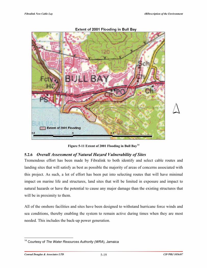
Fibralink New Cable Lay 4BDescription of the Environment
Conrad Douglas & Associates LTD CD*PRJ 1056/07 5-19
Figure 5-11 Extent of 2001 Flooding in Bull Bay14
5.2.6 Overall Assessment of Natural Hazard Vulnerability of Sites
Tremendous effort has been made by Fibralink to both identify and select cable routes and
landing sites that will satisfy as best as possible the majority of areas of concerns associated with
this project. As such, a lot of effort has been put into selecting routes that will have minimal
impact on marine life and structures, land sites that will be limited in exposure and impact to
natural hazards or have the potential to cause any major damage than the existing structures that
will be in proximity to them.
All of the onshore facilities and sites have been designed to withstand hurricane force winds and
sea conditions, thereby enabling the system to remain active during times when they are most
needed. This includes the back-up power generation.
14 Courtesy of The Water Resources Authority (WRA), Jamaica

Fibralink New Cable Lay 4BDescription of the Environment
Conrad Douglas & Associates LTD CD*PRJ 1056/07 5-20
5.3 Biological Environment
5.3.1 Bull Bay, St. Andrew
The project site is located in a coastal area in an existing residential area and consists of the
landing site and the cable housing. It is located just outside and to the east of the Port Royal
Protected Area.
5.3.1.1 Marine Flora, Fauna and Habitats
A marine assessment was conducted along a corridor no more than 1 m wide; the cable is no
more than 28.8 mm wide, of the marine environment. The marine assessment utilized dives of
the area, video and still photography to document the condition of the seabed and associated
structures and marine life in the study area. The depth of the assessment was up to a maximum
of 18 m (60ft) which characterised the inshore.
The inshore has a relatively flat substrate of white calcareous sand from near shoreline to about
450-500 m where offshore distinction is made. This represents a depth of approximately 18 m
(60ft). Based on the marine survey, the area is made of soft sandy substrate. It is accepted that
various fishes (reef and otherwise) and other marine fauna may traverse the cable route.
However, due to the nature of the cable laying activities and size of the cables being laid any
interactions with marine fauna will be negligible. Of importance is the fact that no coral reefs lie
in the path of the proposed cable route. There is no coral reef substrate along the survey path or
rocky outcroppings.
Plate 5-1: Beach character [Note: retaining wall approximately 30 m from shoreline]

Fibralink New Cable Lay 4BDescription of the Environment
Conrad Douglas & Associates LTD CD*PRJ 1056/07 5-21
5.3.1.2 Wildlife Resources
The landing site is located on a strip of coastal land bordered by the sea on the south and the
main road to the north. There are no trees or plants on the strip of beach; hence no nesting birds
were seen in the area. Several marine bird species were observed such as gulls but none nest
nearby or would be affected by cable laying activities on the seabed. No crab holes or crabs were
observed.
5.3.1.3 Vegetation Resources
Landing Site - There is no vegetation community at the site. The site is a commercial property in
close proximity to the main road. There are a few trees on the property but none that is
considered endemic or rare, namely Piscidia piscipula (dogwood). The plant life is
predominantly grasses at the road verge and eastern boundaries of the property and few invasive
plant species such as Antigonon leptopus (Coralita).
Cable Housing Site - The cable house is to be sited at the existing AT&T facility which has
manhole and underground conduits in place. As such, no disturbance of existing terrestrial
community adjoining property is necessary. The cable will be routed from manhole at the
landing site and taken via the road verge to the existing cable station.
Plate 5-2: View from the shoreline (Looking northwest)

Fibralink New Cable Lay 4BDescription of the Environment
Conrad Douglas & Associates LTD CD*PRJ 1056/07 5-22
Plate 5-3: New Little Copa Club Parking Lot
Plate 5-4: Vegetation at the New Little Copa Club

Fibralink New Cable Lay 4BDescription of the Environment
Conrad Douglas & Associates LTD CD*PRJ 1056/07 5-23
5.3.2 Prospect, St. Thomas
5.3.2.1 Marine Flora, Fauna and Habitats
Landing Site - A marine assessment was conducted along a corridor no more than 1 m wide.
The marine assessment utilized dives of the area, video and still photography to document the
condition of the seabed and associated structures and marine life in the study area. The depth of
the assessment was in excess of 30 m (98.4 ft).
The seafloor within the study area could be described as a submerged carbonate platform, which
appears to underlie loose and well bedded sedimentary deposits extending in depth from 5 m to
30 m (Figure 5-12).
ADDITIONAL KEY
1. HARD SUBSTRATE (REEF)
2. LOCATION OF SMALL PATCH
REEF
3. SOFT SUBSTRATE (SAND)
1
1
1
2
2
1A
ADDITIONAL KEY
1. HARD SUBSTRATE (REEF)
2. LOCATION OF SMALL PATCH
REEF
3. SOFT SUBSTRATE (SAND)
1
1
1
2
2
1A
Figure 5-12: Substrates Observed / Interpreted Along Proposed Alignment [Base Image 1991 Aerial Image –
Survey Dept.]
The benthic lifeforms present on the hard submerged substrates within the study area were
colonized predominantly by turf and macro algae, with scattered corals also being present. The
corals observed had diameters between 15 and 45 cm, and were primarily of the Mustard Hill
Coral variety (Porities asteroides). Plating coral varieties, particularly Lettuce Coral (Agaricia

Fibralink New Cable Lay 4BDescription of the Environment
Conrad Douglas & Associates LTD CD*PRJ 1056/07 5-24
sp.) were also observed, as well as a few examples of large boulder corals, particularly Smooth
Starlet Coral (Siderastrea radians).
Scattered to dense growths of both Turtle grass (Thalassia testudinum) and Manatee Grass
(Syringodium filiforme.) were observed growing on the sandy substrates within the study area.
Turtle grass was observed growing at depths of 1 m to 5 m, while Manatee grass was observed
growing in depths of up to 10 m.
Percentage cover relationships between coral and algae benthic lifeforms on hard substrates were
in the order of 12% coral cover to 88% algae cover.
The dominant mobile lifeforms observed at the study area were fish, specifically Sergeant Major
(Abudefduf saxatilis), Dusky Damselfishes (Stegastes fuscus), and Bluehead Wrasses
(Thalassoma bifasciatum).
Numbers of each species observed were low, estimated at less than 10 individuals per 100 cubic
meters of water surveyed over the reefs. Overall sizes of the individuals observed were also low,
being less than 15 cm in length.
Plates depicting the marine environment are presented in Appendix IV.
Conclusions:
1. The marine study area represents a shallow moderately deep area underlain with a hard
carbonate substrate, with a sand channel (approximately 100 meters wide) bisecting the
hard substrate.
2. The percentage cover relationships between coral and algae observed on the hard
carbonate substrate suggest a coral reef in various stages of stress, due to eutrophication.
3. Two seagrass lifeforms were present within the shallow (<10 m) sections of the sand
channel observed within the study area, with Turtle Grass being present on sand in water
depths of less than 5 m, and Manatee Grass being present in water depths of less than 10
m.

Fibralink New Cable Lay 4BDescription of the Environment
Conrad Douglas & Associates LTD CD*PRJ 1056/07 5-25
4. The fish types, numbers and sizes observed within the study area were indicative of an
area that may be suffering either from habitat degradation or over fishing, or both.
5.3.2.2 Wildlife Resources
No bird species were observed on the site. In addition, no crab holes were observed at the site.
5.3.2.3 Vegetation Resources
Landing Site - The landing site is located in the vicinity of the community of Prospect (Ocean
View Close). The vegetation communities observed, are a remnant of the original vegetation,
and only contain a portion of the species usually found in a typical coastal community.
Beach pioneer plants such as Coccoloba uvifera (Sea grape), Sesuvium portulacastrum (Seaside
purslane), and Thespesia populnea (Seaside Mahoe) were present. This vegetation type is sparse
and merges into the road verge approximately 3 m inland.
Inland, succession in vegetation type was observed with a transition to shrubs and grasses.
However, this is interrupted rapidly by the organised residential community. Only one
undeveloped lot was found close to the landing site. The majority of the trees at the site consisted
of mature tree species, approximately 2 m (6 ft) in height. The shrub layer was not well
represented, and large areas under the trees were bare. The shrub layer was consistent with
Panicum maximum (guinea grass). The dominant plants were the Sea Grape (Cocoloba uvifera)
and West Indian Almond (Terminalia catappa), trees common in coastal locations. The substrate
showed variations including sandy and loamy.
There were no endemic, rare, threatened or endangered plant species observed at the site.
Additionally, none of the plants have significant cultural or economic value. None of these trees
will be removed to construct the manhole, which will be dug at the end of the dead end section of
Ocean View Close.

Fibralink New Cable Lay 5BSocio-Cultural Environmental
Conrad Douglas & Associates LTD CD*PRJ 1056/07
SOCIO-CULTURAL ENVIRONMENTAL

Fibralink New Cable Lay 5BSocio-Cultural Environmental
Conrad Douglas & Associates LTD CD*PRJ 1056/07 6-1
6 Socio-Cultural Environmental
6.1 Introduction
Fibralink Jamaica Limited has a vested interest in the opinions, attitudes and views of the
constituents of the communities in which it does business. As mentioned elsewhere in this report,
this project is relatively non-intrusive and thus has a very narrow sphere of physical influence on
people or communities. This report presents the findings of a socio-economic survey conducted
in July-August 2007 among residents within the radius of influence of the project.
6.2 Methodology
While the selection of the areas for interviewing were based on the enumeration districts as
defined by Statistical Institute of Jamaica (STATIN), the communities as presented in this report
were defined in the field by the interviewer and the respondent. Accordingly it is possible for a
number of communities to cross Enumeration Districts (ED) boundaries. Table 6-1 outlines the
EDs surveyed within the sphere of influence of proposed landing sites for Bull Bay, St. Andrew
and Prospect, St. Thomas.
Table 6-1: Enumeration Districts Surveyed
Enumeration District & Code Total Households 5 % Sample Value
Bull Bay Landing Site, St. Andrew
East Rural 082 172 9
East Rural 083 276 1
East Rural 084 200 10
East Rural 087 125 6
East Rural 088 160 8
East Rural 089 89 4
East Rural 090 162 8
East Rural 091 227 11
East Rural 092 156 8
TOTAL 1024
66

Fibralink New Cable Lay 5BSocio-Cultural Environmental
Conrad Douglas & Associates LTD CD*PRJ 1056/07 6-2
Enumeration District & Code Total Households 5 % Sample Value
Prospect Landing Site, St. Thomas
East 086 161 8
East 087 239 12
East 089 200 10
East 090 106 5
East 091 217 11
East 092 271 14
East 093 171 9
TOTAL 1365 68
A Total of 160 surveys were conducted across both proposed landing sites. The surveys were
conducted in 10 EDs in the Bull Bay area and 7 EDs in the Prospect area as outlined by the
STATIN, which were in relatively close proximity to the proposed project sites. The survey
population was devised based on a 5% sample of the Total Households in the area. Figure 6-1
and Figure 6-2 outline the communities surveyed.
ER
82ER 84
ER 83ER 88
ER 87ER 89
ER 92
ER 91
ER
90
ER
82ER 84
ER 83ER 88
ER 87ER 89
ER 92
ER 91
ER
90
Figure 6-1: Enumeration Districts Surveyed for Bull Bay Landing Site, St. Andrew

Fibralink New Cable Lay 5BSocio-Cultural Environmental
Conrad Douglas & Associates LTD CD*PRJ 1056/07 6-3
E87
E86
E89
E92E90
E91
E93
E87
E86
E89
E92E90
E91
E93
Figure 6-2: Enumeration Districts Surveyed for Prospect Landing Site, St. Andrew
6.3 Survey Findings
6.3.1 Segment 1: Bull Bay Proposed Landing Site
6.3.1.1 Demographic and Social Profile
A total of 68 respondents were covered in this survey, 24 women and 38 men; four surveys
showed no response. The majority of the survey population were in the following age groups 22-
35 and 36-50 year age group which accounted for 23 respectively. The majority, 43 (65%), of the
total survey population have lived in the community for twenty years or more. The total
population identified for this area in the 2001 census was 1,024. The information on age and
numbers of years lived in the community are presented in the table below.

Fibralink New Cable Lay 5BSocio-Cultural Environmental
Conrad Douglas & Associates LTD CD*PRJ 1056/07 6-4
Table 6-2: Age and Years of Residency within each Community/ED
Community
Parameter
GreenvaleRoad
Clement
ClaymontRoad
Palm
Beach
HarbourView
Copacobana
PleasantView
Bayview
ShootersHill
TenMiles
NineMiles
EightMiles
SevenMiles
Total
AGE
16 21 years 0 0 0 0 0 1 1 0 0 0 0 1 0 3
22 35 years 0 1 1 0 1 4 6 0 2 3 3 2 0 23
36 50 years 1 0 1 1 2 4 2 0 0 2 1 8 1 23
50+ years 0 0 0 0 2 1 0 5 3 2 3 1 0 17
*NR 0 0 0 0 0 1 0 0 0 0 0 0 0 1
Total 1 1 2 1 5 11 9 5 5 7 7 12 1 67
YEARS OF RESIDENCY
0 5 years 0 0 0 0 1 0 1 0 0 0 0 1 0 3
6 10 years 0 0 0 0 0 2 2 0 2 0 2 0 0 8
11 20 years 0 0 1 1 2 4 3 0 0 0 0 2 0 13
20+ 1 1 1 0 3 4 3 5 3 7 5 9 1 43
*NR 0 0 0 0 0 1 0 0 0 0 0 0 0 1
Total 1 1 2 1 6 11 9 5 5 7 7 12 1 68
*NR – No Response
6.3.1.2 Awareness of Fibre Optic Cables & its Impact on the Environment
Approximately 80% (54) of respondents did not know what fibre optic cables were, and those
that knew seven stated that they are glass cables that transmit information at a faster and cheaper
rate.
Sixty-two percent (42) of respondents were aware that the fibre optic cables will bring cheaper,
faster and better quality international data transfer, cable TV and high speed internet. Seventy-six
percent (52) of respondents believed fibre optic cables would benefit them, of which 28% were
of the view they would benefit from receiving information faster and cheaper. The respondents
who hold the view that the fibre optic cables will bring lower cost for services comprised 41% of
the survey population. The respondents also expressed that fibre optic cables will assist with

Fibralink New Cable Lay 5BSocio-Cultural Environmental
Conrad Douglas & Associates LTD CD*PRJ 1056/07 6-5
easier access to information. The general view on the presence of the fibre optic cables is its
ability to attract better services and less expensive.
Of 37 responses, 55% of respondents that answered were of the view that the cable would have
no effect on the environment. Less than 19% were unsure, with 11% of the view it would impact
air and water quality. Seven percent of respondents were of the view the cables would impact on
their health with 21% voicing concerns on the environment and recreation (Figure 6-3). Eighty-
four percent (57) of the respondents expressed no problems with this project.
I think the presence of the cables will
impact my:7%
5%6%
26%
35%
12%
9%Health
Finances
Better services
Environment
Recreation
Don't Know
No Response
Figure 6-3: Perceived Impact of Fibre Optic Cables
6.3.1.3 Existing & Future Service Amenities
Ninety-seven percent (66) of respondents owned cellular phones while 54% (37) have wired
telephones (landline) at home. Thirty-two percent (22) owned computers with 18% of them
having internet access at home. At least 84% of respondents have Cable TV and/or DSS systems.

Fibralink New Cable Lay 5BSocio-Cultural Environmental
Conrad Douglas & Associates LTD CD*PRJ 1056/07 6-6
Which of the following do you have
in your home?
0%
6% 1% 19%
34%29%
11%Land Telephone
Cellular Telephone
Cable Tv
Satell ite Dish/ DSS
Computer
Internet Access
No Response
Figure 6-4: Technology in Home
The Internet is significant to most of the respondents interviewed. The internet is primarily used
by the respondents primarily at home, work and school. Sixteen percent (16) of persons
interviewed had members of their household who did not use the internet at all. Less than 5% of
respondents do not know how to use the internet or regard it with little significance. Five percent
of respondents are of the view that the cost of accessing the internet is too expensive.
The expectancies of the various communities surveyed are as follows:
Faster money remittance services (Eg. Western Union, Money Gram) – 50%
To be able to research information easily – 50%
More computers in schools – 82%
More computers in Communities (e.g. Post Offices and Libraries) – 68%
Computers in more homes – 79%
Internet Access in more homes – 50%
6.3.2 Segment 2: Prospect Proposed Landing Site
6.3.2.1 Demographic and Social Profile
A total of 73 respondents were covered in this survey, 33 women and 40 men. The majority of
the survey population were of the 36-50 years age group. The majority, 35 (~48%), of the total

Fibralink New Cable Lay 5BSocio-Cultural Environmental
Conrad Douglas & Associates LTD CD*PRJ 1056/07 6-7
survey population have lived in the community for twenty years or more. The total population
identified for this area in the 2001 census was 1,365. The information on age and numbers of
years lived in the community characteristics are presented in the table below (Table 6-3).
Table 6-3: Age and Years of Residency within each Community/ED
Community
Parameter
Oxford
Road
LeithHall
PortMorant
John’sTown
Road
Lyssons
Retreat
Prospect
Total
AGE
16 21 years 0 0 0 0 2 0 2 4
22 35 years 1 2 2 0 6 2 10 23
36 50 years 2 4 5 8 6 3 5 33
50+ years 0 1 3 0 2 1 6 13
Total 3 7 10 8 16 6 23 73
YEARS OF RESIDENCY
0 5 years 0 1 0 0 1 1 6 9
6 10 years 1 0 1 1 3 3 5 14
11 20 years 2 0 0 2 3 2 6 15
20+ 0 6 8 5 9 1 6 35
Total 3 7 9 8 16 7 23 73
6.3.2.2 Awareness of Fibre Optic Cables & its Impact on the Environment
Approximately 66% (43) of respondents did not know what fibre optic cables were, and those
that knew (34%) stated that they are glass cables that transmit information at a faster and cheaper
rate.
Seventy percent (51) of respondents were aware that the fibre optic cables will bring cheaper,
faster and better quality international data transfer, cable TV and high speed internet. Eighty-five
percent (62) of respondents believed fibre optic cables would benefit them, of which 29% were
of the view they would benefit from receiving information faster and cheaper. The respondents
who hold the view that the fibre optic cables will bring communication benefits consisted of 10%
of the survey population.

Fibralink New Cable Lay 5BSocio-Cultural Environmental
Conrad Douglas & Associates LTD CD*PRJ 1056/07 6-8
The respondents also expressed that fibre optic cables will assist with easier access to
information. The general view on the presence of the fibre optic cables is its ability to attract
better services and less expensive.
Of 37 responses, 55% of respondents that answered were of the view that the cable would have
no effect on the environment (Figure 6-5). Less than 19% were unsure, with 11% of the view it
would impact air and water quality. Of 27 responses, 5 respondents were of the view the cables
would impact on their health with 4 each with concerns on the environment and recreation.
Eighty-seven percent of the respondents expressed no problems with this project.
I think the presence of the cables will
impact my:4%3% 0%3%
27%
49%
4%
10%
Health
Finances
Better services
Environment
Recreation
Don't Know
No Response
Other
Figure 6-5: Perceived Impact of Fibre Optic Cables
6.3.2.3 Existing & Future Service Amenities
Ninety-five percent (69) of respondents owned cellular phones while 55% (40) have wired
telephones (landline) at home (Figure 6-6). Thirty-six percent (26) owned computers with 11%
of them having internet access at home. At least 56% of respondents have Cable TV and/or DSS
systems.

Fibralink New Cable Lay 5BSocio-Cultural Environmental
Conrad Douglas & Associates LTD CD*PRJ 1056/07 6-9
Which of the following do you have
in your home?
20%
34%
27%
0%
13%
6%
Land Telephone
Cellular Telephone
Cable Tv
Satellite Dish/ DSS
Computer
Internet Access
Figure 6-6: Technology in Home
The Internet is significant to most of the respondents interviewed. The internet is used by the
respondents primarily at home, work and school. Fourteen percent (15) of persons interviewed
had members of their household who did not use the internet at all. Less than 6% of respondents
do not know how to use the internet or regard it with little significance. Nine percent (11) of
respondents are of the view that the cost of accessing the internet is too expensive.
The expectancies of the various communities surveyed are as follows:
Faster money remittance services (Eg. Western Union, Money Gram) – 34%
To be able to research information easily – 49%
More computers in schools – 86%
More computers in Communities (e.g. Post Offices and Libraries) – 63%
Computers in more homes – 60%
Internet Access in more homes – 48%
6.3.3 Impact on the Marine Community (Fishermen, Bathers etc.)
6.3.3.1 Prospect Region
Most respondents do not depend on the sea to make a living, however, a substantial number of
persons; particularly in Port Morant are fish vendors. Port Morant is the fishing beach used the

Fibralink New Cable Lay 5BSocio-Cultural Environmental
Conrad Douglas & Associates LTD CD*PRJ 1056/07 6-10
most by residents followed by Lyssons Beach, Leith Hall and Prospect. Bathing and/or marine
recreation accounted for less than 5 percent of respondents answers.
Within this region most fishermen (78%) have not excelled in the education system further than
Secondary School and 7% of fishermen do not have any formal schooling. At least 17 fishermen
have been working for 20 years or more, most belonging to associations such as Port Morant
Fishing Association, St. Thomas Fishing Cooperation and Leith Hall.
Of the 26 respondents that were identified as fishermen, 65% were in business for more than 20
years. Most can be characterised as professional fishermen; less than 2% considered themselves
recreational fishermen. The majority of the fishermen were out at sea at least 3 times per week.
Earnings are on average less than $10,000 per week.
Line fishing accounted for at least 40% of all catches with nets 33% predominantly from 28 ft.
fishing vessels largely from Leith Hall and Port Morant with representation of 15% and 48%
respectively. Anchors and mooring buoys were identified as the systems used with anchors
accounting for more than 63%.
When asked how submarine cables would impact there life, the majority (69%) stated that it
would either have a positive impact or no impact at all whilst a few (19%) thought the submarine
cables would have a negative impact. Twelve percent were unsure of its impact.
Most fishermen have no other income (80%), while farming made up 16% of some, and 4%
supplementing their income through crab hunting.
6.3.3.2 Bull Bay Region
At least 56% of respondents do not depend on the sea to make a living; of those that made a
living from the sea, the communities of Nine Miles and Seven Miles were most represented. Of
36 positive responses, 30 used the area for fishing. Nine Miles Beach is the fishing beach used
the most by respondents followed by Bull Bay Fishing Beach, Palm Beach and Seven Miles
Beach. Bathing and/or marine recreation accounted for less than 5 percent of respondents
answers.

Fibralink New Cable Lay 5BSocio-Cultural Environmental
Conrad Douglas & Associates LTD CD*PRJ 1056/07 6-11
Of 22 responses, only 11 fishermen have not excelled in the education system further than
Secondary School. Of the 22 respondents that were identified as fishermen, 45% were in
business for more than 20 years. Most can be characterised as professional fishermen; less than
2% considered themselves recreational fishermen. Approximately 50% of the fishermen were out
at sea at least 3 times per week. Earnings are on average less than $10,000 per week. Fishermen
in the area belong to associations such as Kingston Fishing Co-Op and the Fishing Co-Op of the
Fisheries Division.
Line fishing accounted for at least 41% of all catches with nets 39% with about 75% fishing
from 28 ft. fishing vessels. Anchors and mooring buoys were identified as the systems used with
anchors accounting for more than 71%.
When asked how submarine cables would impact their life, the majority (44%) stated that it
would either have a positive impact or no impact at all whilst 39% thought the submarine cables
would have a negative impact.
Fifty percent of fishermen identified in this region have other sources of income such as:
carpentry (28%) and welding (8%) to supplement their income.
6.3.4 Interpretation
The majority of respondents surveyed are open to the installation of the fibre optic cables. They
are willing to learn more about the opportunities and effects, and believe that it will generally
make a positive impact on them.
Many highlighted that Businesses would be boosted by this new development, as a result of
faster transactions internationally and locally. The vast majority of those surveyed were also
aware that fibre optic cables can provide audio-video (cable), data (internet), and (audio-voice)
landline capabilities. Most have cellular phones and cable TV, and are aware of technological
advances in communication.
Better services were the primary impact from the presence of the cables to most respondents who
viewed it as a positive through increased savings etc. Health, the environment and recreation
were minor impact areas identified. The major concerns expressed were health is a major

Fibralink New Cable Lay 5BSocio-Cultural Environmental
Conrad Douglas & Associates LTD CD*PRJ 1056/07 6-12
concern of respondents as it relates to the impact from the cables. Sixty-five percent of
respondents were of the opinion it would not impact the environment negatively.
Of those that rely on the sea for their livelihood by fishing, anchors were the primary technology
used on boats with a minority using mooring buoys.

Fibralink New Cable Lat 6BDetermination of the Potential Impacts of the Proposed Project
Conrad Douglas & Associates LTD CD*PRJ 1056/07
DETERMINATION OF THE POTENTIAL
IMPACTS OF THE PROPOSED PROJECT

Fibralink New Cable Lat 6BDetermination of the Potential Impacts of the Proposed Project
Conrad Douglas & Associates LTD CD*PRJ 1056/07 7-1
7 Determination of the Potential Impacts of the Proposed Project
7.1 Introduction
In the process of undertaking this Marine Assessment, several potential impacts of the proposed
project have been identified for each phase of the development. Impacts are evaluated in terms of
the actual risk of occurrence, the extent (spatial) and duration, and severity. Cumulative effects
of potential impacts of this project in conjunction with the impacts of existing
activities/operations are also considered.
Appropriate mitigation measures are also recommended for the various potential impacts
identified.
In assessing the significance of potential impacts, various measures are used. These include the
use of checklists/matrices, expert knowledge and a keen assessment of the project plans and
details. Each parameter is evaluated according to the following:
Potential impact - any change to the environment, whether adverse or beneficial, wholly
or partially resulting from the proposed activities, products or services
Activity – phase of development that action takes place in
Environmental receptor - sensitive component of the ecosystem that reacts to or is
influenced by environmental stressors
Magnitude - A measure of how adverse or beneficial an effect may be
Duration - the length of time needed to complete an activity
Significance - A measure of importance of an effect
Mitigation - Measures taken to reduce adverse impacts on the environment
Also presented are impact matrices (identification and mitigation) that summarise the impacts
identified and the mitigations proposed for this project.
The following potential impacts are related to the key aspects of the proposed project. There are
no adverse unavoidable negative environmental impacts related to the proposed project. The
potential environmental impacts identified for the pre-construction, construction and operating
phases of the proposed project includes:

Fibralink New Cable Lat 6BDetermination of the Potential Impacts of the Proposed Project
Conrad Douglas & Associates LTD CD*PRJ 1056/07 7-2
Negative
Minimal suspended solids during cable laying
Minimal noise and vibration during construction
Minimal aesthetics and transient change of land and marine use
Positive
Improved broadband access by connection to other islands
Potential vast increase in investment revenue and job creation due to improvements in the
telecommunications industry from this project.
No loss of biodiversity
No loss of archaeological and historical heritage resources
No loss of aesthetic appeal
No loss of commercial and recreational fishing needs.
Table 7-1: Potential Sources of Environmental Impacts
No. Types of likely environmental issuesConstruction
Phase
Operational
Phase
1 Gaseous emissions
2 Dust
3 Odour
4 Noise
5 Night time operations
6 Traffic generation
7 Liquid effluents, discharges, or contaminated runoff
8 Generation of waste or by products
9 Storage, handling, transport or disposal of hazardous
materials or wastes
10 Risks of accidents which would result in pollution or
hazard
11 Disposal of spoil material
12 Disruption of water movement or bottom sediments
13 Unsightly visual appearance
14 Ecological impacts (Marine)

Fibralink New Cable Lat 6BDetermination of the Potential Impacts of the Proposed Project
Conrad Douglas & Associates LTD CD*PRJ 1056/07 7-3
No. Types of likely environmental issuesConstruction
Phase
Operational
Phase
Key Potential to cause concern
Unlikely to cause concern

Fib
rali
nk
New
Ca
ble
La
t 6
BD
eter
min
ati
on
of
the
Po
ten
tia
l Im
pa
cts
of
the
Pro
po
sed
Pro
ject
Co
nra
d D
ou
gla
s &
Ass
oci
ate
s L
TD
C
D*
PR
J 1
05
6/0
7
7-4
7.2
Po
ten
tia
l Im
pa
cts
[Ph
ysi
cal,
Bio
log
ica
l, S
oci
o-C
ult
ura
l]
Activity
Environmental
receptor
Typeof
Impact
PotentialIm
pact
Mitigation
Duration
Significance
Level
Likelihood
7.2
.1A
esth
etic
s
Construction
Humans,Flora
&Fauna
Negative
Item
A1–Theclearance
andremovalofany
vegetationfrom
thelandingsitesandproposedcable
stationwillresultinavisuallynegativeim
pactandloss
ofnaturalresources.Thesm
allbuildingsthatwill
house
theequipmentwillbeoflowprofileand
footprint(exceptfortheBullBaysite
whichis
existing),andfitinto
theexistingsurroundings.
Allactivitiesonthesite
willbecarefullyexaminedto
ensure
aslittleim
pactonthesurrounding
communitiesaspossible
Properupkeepandmaintenance
ofthesite
willbedone.Landscapingand
buildingorientationwillbeutilizedwhere
necessary
toenhance
thevisual
aesthetics
oftheareas.
Short
Term
Minor
Negative
Moderate
7.2
.2W
ate
r Q
uali
ty/S
urf
ace
Wate
r H
ydro
logy
an
d G
rou
ndw
ate
r
Construction
&Operation
Humans,Flora
andFauna
Minor
negative
Item
WQ1–Itmightbesuggestedthatthepresence
ofthecablesinthewatermaydecrease
thewater
quality;however,theyshouldpose
nothreatandwill
notalterthequality
ofthewater.Temporary
impacts
onwaterquality
mayberealizedduringthecable
landingoperations.Thishowever,shouldbeshortin
durationandlimitedintheamountofsedim
entation
thatitcauses.
Nochemicalim
pactsare
anticipatedon
waterquality.
Nomitigationnecessary.
Short
term
Minor
Negative
Low
Construction
Humans,Flora
andFauna
Minor
negative
Item
WQ2
Silting/Sedim
entationmayoccurasa
resultofexcavationofsoilforthemanhole,trenching
forlayingthecable,orfrom
directionaldrilling.
Thetimelyremovalofremovedand/orstocpiledsoilsandtheuse
of
containment(berm
s,bundsorcontainers)to
secure
soilsandavoidsiltation,etc.
duringincidence
ofrainfall.Propersecuringofanystockpiles
Short
term
Minor
Negative
Low
7.2
.3A
ir Q
uali
ty
Item
AQ1–Itispossiblethatasm
allamountof
fugitivedustmaybeproducedduringmanhole
constructionatthelandingsite.Trenchingalongthe
roadwayalsohasthepotentialforobservablefugitive
dust.Otherw
ise,thisprojectshouldnotresultinany
negativeairquality
eventsasitrelatesto
fugitive
dust.
Excavatedsoilandexposedsoilsurfaceswillbesprinkledasnecessary
andnot
allowedto
dry
outenoughto
becomeentrainedinwind.
Short
Term
Minor
Negative
Medium
Construction
Humans,Flora
andFauna
Negative
Item
AQ2–Limitedheavyequipmentwillbeusedand
onlyforshortperiods.Emissionswilltherefore
notbe
prolonged,andthisisconfinedto
theinstallation
period.Operationwillnotgenerate
anyappreciable
Heavyequipmentwillbemaintainedinproperworkingconditionto
produce
minim
alemissions.
Short
Term
Minor
Negative
Low

Fib
rali
nk
New
Ca
ble
La
t 6
BD
eter
min
ati
on
of
the
Po
ten
tia
l Im
pa
cts
of
the
Pro
po
sed
Pro
ject
Co
nra
d D
ou
gla
s &
Ass
oci
ate
s L
TD
C
D*
PR
J 1
05
6/0
7
7-5
Activity
Environmental
receptor
Typeof
Impact
PotentialIm
pact
Mitigation
Duration
Significance
Level
Likelihood
amountsofemissions.Thisprojectshouldnotresult
inanynegativeairquality
eventsasitrelatesto
gaseousemissions.
7.2
.4N
ois
e &
Vib
rati
on
Construction
Humansand
Fauna
Negative
Item
N1–Variousmechanicalequipment,vehicles
andsite
activitiesmaygenerate
noisethatmay
exceedacceptablelevels.Itisnotexpectedthatthe
projectwillcause
anoisenuisance
atanypoint,that
is,neitherduringinstallationnoroperation.Where
necessary,work
requiringheavyequipmentwillbe
scheduledfordaytimeandwillbebriefto
minim
ize
thepotentialfordisruptionofresidentsandguests.
Operationwillnotproduce
anynoise.
Allequipmentusedwillbeproperlyservicedandingoodworkingcondition.Any
equipmentthatisdeemedto
betoonoisywillberemovedfrom
servicefor
repairorreplacement.Personnelshouldwearearprotection(e.g.earplugs).
Short
Term
Minor
Negative
Low
7.2
.5W
ildli
fe &
Veg
etati
on
Res
ou
rces
Construction
and
Operation
Fauna
Negative
Item
WVR1–Thelandingsitesdonotrequireany
landclearance.Themanholeto
beconstructedisnot
largeandismostlyunderground.Directionaldrilling
usedwillnotdisturb
thesoilsurface
nearshore.
Thecablestationto
beconstructedwillnotrequire
theremovalofanysignificantamountofvegetation.
Assuch
thelossofhabitatwillnotbesignificant.
Limittheamountofvegetationto
beremovedto
aminim
um.Introduce
landscapingasnecessary
tothearea.
Short
Term
Minor
Negative
Low
Construction
&Operation
Fauna
Negative
Item
WVR2
Itmaybeassumedthatlayingofany
form
ofcablesontheseafloorwoulddisruptmarine
life,however,itisinthebestinterestofthose
laying
thecablesto
avoidcoralsorotherstructuresin
order
toprotectthecable.Thecableisto
belaid
completelyflatontheseafloor.
Inthecase
ofthe
Prospect,St.Thomaslandingsite,thecablewillbe
laidthroughanareaofseagrass
andisunavoidable.
Every
effortwillbemadeto
minim
izetheareasof
seagrass
interruptedandmitigationmeasureswill
beim
plemented.
Inareaswhere
seagrassisunavoidableitisproposedthatbasedonthesize
of
thecabletheseagrassovertimewillgrowoverthecabletherebyconcealingit.
Assuch
nomitigationisproposed.
Short
Term
Minor
Negative
Low

Fib
rali
nk
New
Ca
ble
La
t 6
BD
eter
min
ati
on
of
the
Po
ten
tia
l Im
pa
cts
of
the
Pro
po
sed
Pro
ject
Co
nra
d D
ou
gla
s &
Ass
oci
ate
s L
TD
C
D*
PR
J 1
05
6/0
7
7-6
Activity
Environmental
receptor
Typeof
Impact
PotentialIm
pact
Mitigation
Duration
Significance
Level
Likelihood
7.2
.6E
mplo
ymen
t &
Soci
o-E
con
om
ic I
mpact
s
Item
E1–Whenfullyim
plemented,i.e.thecablehas
beeninstalledandtheinfrastructure
hasbeen
prepared,theprojectwillresultinsignificantjob
creationacrosstheisland.Jobswillberealizedthough
increasedtelecommunicationandotherrelated
industriesontheisland.
Allthephasesoftheprojectim
plementationwill
generate
localemployment(somemore
thanothers)
butthecumulativeim
pactwillbesignificantlyand
positivefortheJamaicaneconomy.
Positiveim
pact.NOMITIGATIONisREQUIRED
Long
Term
Major
Positive
Moderate
Operation
Humans
Positive
Item
E2–Dueto
theserviceswhichcanbereceived
viainstallationofFibre
Opticcables,such
as,faster
remittance,fastertransm
issionofdata
(sendingand
receiving),overbroadbandinternet,better
telecommunications,saferandless
vulnerable
internationalconnectionsetc.,there
willbeseveral
positiveim
pactsontheentire
island.These
include:
Remittanceswouldbereceivedmore
quickly,
therefore
there
couldbeanincrease
inthe
remittancessentto
theisland.Thiswouldin
turn
meananincrease
inrevenueforthe
country.
Dueto
easieraccess
toinform
ation(internet),
thescopeofknowledgeofindividualswould
increase.Also,theless
timespentobtainingthis
inform
ation,themore
timewouldbeleft
availableforotheractivities.
Jamaicawouldbecomeanexampleinthe
Caribbeanofhighquality
international
telecommunications.Also,ininclementweather,
therisk
ofservicedisruptionwouldbevery
low.
Thisensuresthatproductivityisnotdisrupted.
Cheapercommunicationservice.Withthis
decrease
incost,theservicewouldbeaffordable
tomore
people,im
provingtheoverallstandard
ofliving.
These
are
positiveim
pacts,therefore,NOMITIGATIONisREQUIRED
Long
Term
Major
Positive
High

Fib
rali
nk
New
Ca
ble
La
t 6
BD
eter
min
ati
on
of
the
Po
ten
tia
l Im
pa
cts
of
the
Pro
po
sed
Pro
ject
Co
nra
d D
ou
gla
s &
Ass
oci
ate
s L
TD
C
D*
PR
J 1
05
6/0
7
7-7
Activity
Environmental
receptor
Typeof
Impact
PotentialIm
pact
Mitigation
Duration
Significance
Level
Likelihood
7.2
.7S
oli
d W
ast
e
Construction
Humans
Negative
Item
SW1–Wastestream
intheform
ofpackaging
andrubbleare
potentialsolidwaste.Aproperly
implementedandexecutedsolidwastemanagement
planwillremovethisnegativepotential.Fibralinkhas
existingpoliciesto
handlethisim
pact.
Solidwasteintheform
ofpackagingwasteetc.willberemovedto
anapproved
landfillfacility.Wasterubblenotusedinthereinstatementofroadwayswill
similarlybedisposedofandmaterialfrom
thedirectionaldrillingwhichis
innocuousclaymaterial.
Short
term
Minor
Negative
Low
7.2
.8O
ccu
pati
on
al
Hea
lth
an
d S
afe
ty
Construction
Humans
Negative
Item
OHS1–Fibralinkiscommittedto
thegoalofzero
accidentsandwillemploybestpracticesto
achieve
workerhealthandsafety
compliance.
Adherence
totheexistingoccupationalhealthandsafety
standardsandpolicies
such
asdustabatementtechnologiesandtheuse
ofeyeandhearingprotection
aids.
Long
term
Minor
Negative
Low

Fibralink New Cable Lay 6BDetermination of the Potential Impacts of the Proposed Project
Conrad Douglas & Associates LTD CD*PRJ 1056/07 7-8
7.3 Impact Identification and Mitigation Matrices
Table 7-2: Impact Identification Table - Bull Bay, St. Andrew
Marine Assessment Activities
Landing Site Preparation Cable Installation Cable Station Construction
SiteSurveying
SiteClearance
SolidWasteDisposal
ManholeConstruction
CableLaying(m
arine)
Cablerouting(land)
Trenching
MaterialsSourcing
MaterialsTransport
ConstructionCamp/M
aterialsStorage
ConstructionWorks
SolidWasteDisposal
SewageTreatm
ent
Increasedworkforce
Landscaping
CableStationOperation
TOPOGRAPHY
GEOLOGY
VIBRATION
RAINFALL
GASEOUS EMISSIONS/ ODOUR
AMBIENT NOISE
DUST
DRAINAGE
TEMPERATURE
NATURAL HAZARD VULNERABILITY
Water Quality
SEDIMENTATION
CHEMICAL IMPACT
Ecological Parameters:
TERRESTRIAL ECOSYSTEMS
VEGETATION
BIRDS
OTHER FAUNA
AQUATIC ECOSYSTEMS
VEGETATION
FAUNA
SENSITIVE HABITATS
Socio Economic Parameters:
AESTHETICS
LAND USE COMPATIBILITY
EMPLOYMENT
FOREIGN EXCHANGE EARNINGS
STRUCTURES/ROADS
WASTE MANAGEMENT
TRAFFIC ON THE ACCESS ROAD
INCREASED CRIME
HAZARD VULNERABILITY
SOLID WASTE DISPOSAL
SEWAGE DISPOSAL
FISHING INDUSTRY
Occupational Health & Safety

Fibralink New Cable Lay 6BDetermination of the Potential Impacts of the Proposed Project
Conrad Douglas & Associates LTD CD*PRJ 1056/07 7-9
KEY
Major Negative
Minor Negative
No Impact
Major Positive
Minor Positive
Table 7-3: Impact Identification Table - Prospect, St. Thomas
Marine Assessment Activities
Landing Site Preparation Cable Installation Cable Station Construction
SiteSurveying
SiteClearance
SolidWasteDisposal
ManholeConstruction
CableLaying(m
arine)
Cablerouting(land)
Trenching
MaterialsSourcing
MaterialsTransport
ConstructionCamp/M
aterialsStorage
ConstructionWorks
SolidWasteDisposal
SewageTreatm
ent
Increasedworkforce
Landscaping
CableStationOperation
TOPOGRAPHY
GEOLOGY
VIBRATION
RAINFALL
GASEOUS EMISSIONS/ ODOUR
AMBIENT NOISE
DUST
DRAINAGE
TEMPERATURE
NATURAL HAZARD VULNERABILITY
Water Quality
SEDIMENTATION
CHEMICAL IMPACT
Ecological Parameters:
TERRESTRIAL ECOSYSTEMS
VEGETATION
BIRDS
OTHER FAUNA
AQUATIC ECOSYSTEMS
VEGETATION
FAUNA
SENSITIVE HABITATS

Fibralink New Cable Lay 6BDetermination of the Potential Impacts of the Proposed Project
Conrad Douglas & Associates LTD CD*PRJ 1056/07 7-10
Marine Assessment Activities
Landing Site Preparation Cable Installation Cable Station Construction
SiteSurveying
SiteClearance
SolidWasteDisposal
ManholeConstruction
CableLaying(m
arine)
Cablerouting(land)
Trenching
MaterialsSourcing
MaterialsTransport
ConstructionCamp/M
aterialsStorage
ConstructionWorks
SolidWasteDisposal
SewageTreatm
ent
Increasedworkforce
Landscaping
CableStationOperation
Socio Economic Parameters:
AESTHETICS
LAND USE COMPATIBILITY
EMPLOYMENT
FOREIGN EXCHANGE EARNINGS
STRUCTURES/ROADS
WASTE MANAGEMENT
INCREASED CRIME
HAZARD VULNERABILITY
SOLID WASTE DISPOSAL
SEWAGE DISPOSAL
FISHING INDUSTRY
OCCUPATIONAL HEALTH & SAFETY
Table 7-4: Impact Mitigation Table – Prospect & Bull Bay
Proposed Mitigative Measures
Operation&Maintenance
Plan
DetailedBathymetricSurveys
EffectiveSiteManagement
SchedulingofConstructionActivities
WasteManagementPlan
RoadPavingandSurfacing
DustManagementTechniques
InstallationofSedim
entTraps
Flora
&FaunaRelocation
CLEARING OF SITE VEGETATION
LEVELLING OF SITE
TRANSPORTATION OF CONSTRUCTION
MATERIAL
INCREASE IN NOISE

Fibralink New Cable Lay 6BDetermination of the Potential Impacts of the Proposed Project
Conrad Douglas & Associates LTD CD*PRJ 1056/07 7-11
Proposed Mitigative Measures
Operation&Maintenance
Plan
DetailedBathymetricSurveys
EffectiveSiteManagement
SchedulingofConstructionActivities
WasteManagementPlan
RoadPavingandSurfacing
DustManagementTechniques
InstallationofSedim
entTraps
Flora
&FaunaRelocation
INCREASE IN DUST
DISTURBANCE OF FLORA AND FAUNA
AESTHETICS
INCREASED EMPLOYMENT
INCREASED SEDIMENTATION OF COASTAL
WATERS
CHANGE IN THE NATURAL DRAINAGE
PATTERNS
SOLID WASTE GENERATION
INCREASED EARNING POTENTIAL FOR
COMMUNITY
TRAFFIC INCONVENIENCES
Key
No Impact
Minor Negative
Major Negative
Minor Positive
Major Positive

Fibralink New Cable Lay Environmental Management and Monitoring Plan
Conrad Douglas & Associates LTD CD*PRJ 1056/07
ENVIRONMENTAL MANAGEMENT AND
MONITORING PLAN

Fibralink New Cable Lay Environmental Management and Monitoring Plan
Conrad Douglas & Associates LTD CD*PRJ 1056/07 8-1
8 Environmental Management and Monitoring Plan
8.1 Introduction
Any scale of operation that is being started without any existing infrastructure is generally
divided into three phases:
1. Pre-construction phase
2. Construction phase
3. Operational Phase.
All phases require independent monitoring regimes in order to ensure that the integrity of the
environment is preserved.
The type of development being proposed in this Marine Assessment is estimated to have minimal
impact on the environment in all phases. In fact, the only phases which really require monitoring
are the pre-construction phase and the construction phase. The operational phase is automated
and does not involve any extensive operations that require human intervention or the use of
chemicals, physical tools, etc. The operation is also a zero discharge operation and does not
require any frequent input of raw materials other than electricity for sustained operations.
All data recorded, all observations made, and all analytical techniques employed will be
documented, summarized, compiled and submitted to NEPA according to the accepted terms
outlined for each phase of this development, and according to any additional terms outlined in
the permit license, if granted.
8.2 Pre-Construction Phase
This phase involves the preparation of the proposed sites for the facilitation of the development.
Site preparation will occur on the on-shore areas.
For the preparation of the onshore sites, the following measures are proposed:
During site clearing activities, any animals or plants that are in the area designated for the
cable buildings must be evaluated to ensure that no endemic, rare or protected species will
be affected. Any such species identified will be documented and the proper authorities

Fibralink New Cable Lay Environmental Management and Monitoring Plan
Conrad Douglas & Associates LTD CD*PRJ 1056/07 8-2
notified so that the best relocation practice can be employed or if necessary the location of
the building changed to accommodate the species.
Where identified, endemic and rare species should be preserved in place or collected for
transplanting (As Observed)
Stockpiles of soil and vegetative debris generated during site clearing activities should be
monitored and maintained to eliminate generation of fugitive dust. (Daily Monitoring)
Noise levels along the perimeters of the project area should be monitored and recorded to
insure that activities at the site are not exceeding standards. (Daily Monitoring)
8.3 Construction Phase
Construction is slated to occur on both near-shore and onshore areas. Directional drilling will be
employed to bring the cable in from the sea to the nearshore manhole that will be constructed
onshore. Such an activity will warrant the monitoring of turbidity levels of the near shore areas
for the duration of the construction phase. The turbidity levels will provide insight on the
magnitude of the occurrence of processes such as siltation and sedimentation, which may be
caused by the drilling and the on shore construction activities.
Construction at each landing site is estimated to be a one day affair. During the construction
process on the onshore areas the following areas will be monitored:
Solid Waste Management - Ensure that solid waste management plan is prepared, and that
workers are aware that no solid waste material should be scattered around the site. Monitor
availability and location of skips/dumpsters.
Exposed soil areas must be monitored to determine potential for erosion, silting and
sedimentation particularly during storm events. Reinstatement of cuts along roadways must
be done in the shortest possible timeframe. Signs must be erected to highlight areas where
work is being done. (Weekly Monitoring)
If erosion, silting or sedimentation is a potential or occurs, immediate steps must be taken
to negate the impact on the coastal waters and other receptors where applicable. (As
Needed)
If any cultural heritage resources are unearthed during construction activities, activities
should be stopped and the Jamaica National Heritage Trust contacted. (As Needed)

Fibralink New Cable Lay Environmental Management and Monitoring Plan
Conrad Douglas & Associates LTD CD*PRJ 1056/07 8-3
Noise levels along the perimeters of the project area should be monitored and recorded to
insure that activities at the site are not exceeding standards. (Daily Monitoring)

Fibralink New Cable Lay Appendices
Conrad Douglas & Associates LTD CD*PRJ 1056/07
APPENDIX

Fibralink New Cable Lay Appendices
Conrad Douglas & Associates LTD CD*PRJ 1056/07
APPENDIX I

Fibralink New Cable Lay Appendices
Conrad Douglas & Associates LTD CD*PRJ 1056/07 I
Appendix I: Approved Marine Assessment Scope of Detail
Marine Assessment Scope of Detail
Conrad Douglas & Associates Limited (CD&A) has been contracted to conduct the Marine Assessment for the implementation of the proposed Fibre Optic Cable Landing Sites in Jamaica. In keeping with the requirements of the National Environment and Planning Agency (NEPA), CD&A provides this Draft Scope of Detail document for the captioned project.
Background Columbus Communications Jamaica Limited through its Jamaican affiliate Fibralink Jamaica Limited is undertaking the construction and operation of a redundant sub-marine fibre optic cable system in Jamaica to maintain network diversity and reliability. The sub sea fibre cable will connect Boca Raton, Florida with Jamaica and Columbia. This will facilitate continued high quality connectivity and broadband access for Jamaica through another international port to North and South America. This will greatly improve the reliability of the telecommunications industry in Jamaica.
The landing party in Jamaica will be Columbus Networks affiliate and license holder in Jamaica, FibraLink Jamaica Limited.
FibraLink has been awarded a licence to install and operate the fibre optic system by the Office of Utilities Regulation in Jamaica. The proposed landing sites in Jamaica are as follows:
1. New Little Copa Club, Bull Bay, St. Thomas 2. Ocean View Close, Prospect, St. Thomas
This project will present the country with another option for linking with the outside world and provide a level of redundancy to the network to safeguard against total disruption of services in the event of significant natural disasters, representing great economic and social potential. It will serve to drive the cost of e-services down, creating a more affordable environment for commercial and personal broadband communication availability in the island.
Study Area
The study area will include to some extent Jamaica’s territorial waters and two (2) landing sites, namely in the Bull Bay (St. Andrew) and Prospect (St. Thomas) areas. The projected sphere of influence of the study sites is expected to be no more than 2km in radius of identified sites. The Bull Bay site is approximately 1.5 km east of the existing Fibralink fibre optic landing site.
Scope of Work
The Scope of Work requires that a Marine Assessment be carried out. The Scope of Work is listed under the tasks to be undertaken below.
Tasks to be Undertaken

Fibralink New Cable Lay Appendices
Conrad Douglas & Associates LTD CD*PRJ 1056/07 II
The tasks to be undertaken are structured to meet the requirement of the National Environment and Planning Agency (NEPA), Ministry of Health (Environmental Health Unit), Office of Disaster Preparedness and Emergency Management (ODPEM) and all other relevant governmental and regulatory agencies.
Task 1: Project Description
CD&A will identify all the critical activities, equipment and procedures that will be implemented throughout the major stages of the project. The project designs, specifications, and schedules will be clearly presented in this section. The completed project description will include at a minimum, details such as:
Description of the materials of construction and structure of the fibre optic cable. Method of linkages and securing along its alignment as well as linkages from sea to land
Project implementation schedule, descriptions of preconstruction, construction and occupational activities
Detailed description of project components, with special emphasis on those that may cause potential environmental impacts during each phase.
Review of designs with details to show how FibraLink will be able to maintain environmental compliance and not negatively impact the environment. This includes structural, operational and emergency safeguards
Mode of operation, hours of operation and types of machinery and equipment to be used. Special emphasis will be placed on activities that involve the generation of waste materials
The number of employees proposed for the operation
Description of the role of regulatory agencies, NEPA, Parish Council, Marine Police and others in terms of inspections and follow-up visits
The relevance of the project to national development will also be evaluated.
Task 2: Policy, Legislative and Regulatory Framework
All International and Government of Jamaica policies, legislation and regulations relevant to the project will be identified and analysed. This will be a comprehensive analysis from which FibraLink will be advised as necessary to ensure that all phases of the project maintain compliance.
Task 3: Analyses of Alternatives
Alternative landing sites and plans (inclusive of the preferred and no action alternatives) will be evaluated in terms of the economic, logistical, and environmental selection criteria, inclusive of their potential for positive and negative impacts, and the degree to which the negative impacts may be mitigated. In the case of each alternative reviewed a rationale will be provided for selection or non-selection.
Task 3.1: Description of Current and Proposed Broadband Systems in Jamaica
CD&A will utilize both graphical and descriptive approaches to describe and compare the existing fibre optic equipment and capabilities on the island against those of the proposed

Fibralink New Cable Lay Appendices
Conrad Douglas & Associates LTD CD*PRJ 1056/07 III
upgrade, to highlight effectively the benefits both environmentally and economically of the proposed project. This will include at a minimum:
Characteristics of the methods, equipment and processes
Designs, size, scale and capacity
Equipment and machinery
Task 4: Description of Current Environmental Baseline Data
This task seeks to identify the principal parameters of the natural and human environment which may be sensitive to the project, and to compile, analyse, assess and document the present (baseline) status of this environment. This database will provide an invaluable baseline against which future impacts on the environment may be measured. The environmental setting and baseline parameters will address primarily the bio-physical environment and the socio-cultural environment.
The Bio-Physical Environment
Topography, basic land, and marine conditions.
geomorphology and earth surface processes
natural hazard vulnerability and risk
marine environment (territorial waters)
rainfall characteristics
wind speed and direction
background noise levels
water quality surveys
floral and faunal types and their distribution
the ecology of the area (identification of any rare, endangered and threatened species, and habitats)
These studies will incorporate the two (2) proposed landing sites and the surrounding environment/communities that may be impacted. A potential environmental sphere of influence will be developed based on the information collected and the potential for impact.
The Socio-Cultural Environment
Both primary and secondary data sources will be developed involving: documentation of the existing human environment will include a review and analysis of census data. Populations in the environs of the landing sites will be taken into account in compiling the socio-economic baseline information. A coded, pre-tested socio-economic survey instrument will be developed and administered in the communities located within the anticipated sphere of influence of the project. The findings will be presented in a manner to categorize and identify socio-economic impacts (perceived and real) in terms of positive and negative.
Among the key elements which will be addressed are:
the spatial distribution of coastal communities within the sphere of influence of the proposed project
demographic profile

Fibralink New Cable Lay Appendices
Conrad Douglas & Associates LTD CD*PRJ 1056/07 IV
use/dependence on natural resources
knowledge of the proposed project and their disposition towards it
occupations and skills
employment levels
economic activity
relevant historical heritage in the vicinity of the site
Task 5: Impact Identification
All potential impacts on the receptors and attributes of the environment, both adverse and beneficial, will be identified and their duration, magnitude, reversibility, and extent described and quantified. In addition, in the case of positive impacts, recommendations will be made on their maximisation. This will cover all phases of the project. This will include qualitative as well as quantitative assessments. Areas to be addressed will include at a minimum:
Human population of the area
Flora and fauna
Marine environment
Weather and climate
Cultural Heritage Resources
Cumulative impacts will also be addressed by taking into account existing operations in the area, particularly in respect of their contribution to the baseline and the incremental changes which will be caused by the proposed works, if any.
Task 6: Impact Mitigation
An impact mitigation plan will be developed. This will include the measures to be implemented in the environmental action plan for each potentially negative impact identified. These will also include mitigative measures to be applied during all phases of construction and operation to minimise or eliminate any identified negative impacts. Estimated costs to implement the mitigation items in the plan will be presented. Additionally a Disaster Preparedness Plan for the project will be developed based on findings of the Natural Hazard and Vulnerability section of the report.
Task 7: Environmental Management and Training
CD&A will work to develop management and training protocols to govern the actions of employees and contractors within Jamaica’s territorial waters and on land during all phases of the project. The protocols developed will address all the steps which will be taken during the site preparation, construction and operating phases of the project to avoid, or mitigate potential impacts, as well to maximise beneficial impacts. Where necessary, required training activities will be defined and in conjunction with FibraLink these will be developed and tested. This is an important step in the project as it speaks to issues of regulatory compliance, liability, and occupational health and safety.
Task 8: Environmental Monitoring Plan
CD&A will develop an environmental monitoring plan in which all the parameters to be monitored and the methods to be used will be identified and described. This plan will include at a minimum:

Fibralink New Cable Lay Appendices
Conrad Douglas & Associates LTD CD*PRJ 1056/07 V
An organizational/responsibility chart
Institutional arrangements for carrying out the work
Parameters to be monitored
Methods to be employed
Standards, guidelines or protocols to be used
Evaluation of results
Schedule and duration of monitoring
Initiation of mitigative actions
Format and frequency of reporting
Task 9: Risk Assessment/Natural Hazard Vulnerability
All potential physical risks associated with the proposed project, such as hurricanes, earthquakes, fires, explosions, spillages, flood events and landslides will be identified and addressed. Methods to address these will also be documented.
A Disaster Preparedness Plan/Emergency Response Plan for the construction sites will be developed based on the findings of this task and through consultation with the Office of Disaster Preparedness and Emergency Management (ODPEM).
Task 10: Public Participation
CD&A will follow international and national guidelines for public participation that the public, particularly those who may be impacted (negatively or positively) by the project. This will begin as an early stage in planning and project implementation. Public participation will provide early indications of public perception and potential areas where problems may arise and what it may take to handle those situations. While the socio-economic survey will introduce the project to the community through a fact sheet, informal meetings and collaborations will be held with community leaders and members to explain the project.
CD&A recommends the following procedures and schedule for meeting with communities in the estimated radius of influence of the facility:
Procedures:
Identify and classify the various communities in the radius of influence
Identify and involve “community leaders” early in the process
Listen carefully and record the ideas, needs, and wants of the communities (where possible implement their input into the process)
CD&A recommends that this type of interface with the community continue as long as the project is being implemented and beyond if practicable, to foster good community relations.
The Marine Assessment Report
CD&A will present all findings in the Marine Assessment, reflecting the headings in the body of the approved Scope of Detail, as well as other references. Eight (8) hard copies and one electronic copy of the report will be submitted to NEPA. It will include an appendix with items such as maps, site plans, the study team, photographs and other relevant information.

Fibralink New Cable Lay Appendices
Conrad Douglas & Associates LTD CD*PRJ 1056/07 VI
The Marine Assessment Report will take the following form:
Executive Summary
Project Description
Policy, Legislative and Regulatory Framework
Analyses of Alternatives
Description of Current Physical, Environmental and Socio-Economic Baseline Data
Risk Assessment/Natural Hazard Vulnerability
Impact Identification
Impact Mitigation
Environmental Monitoring Plan
Environmental Management and Training
List of References
Appendices

Fibralink New Cable Lay Appendices
Conrad Douglas & Associates LTD CD*PRJ 1056/07
APPENDIX II

Fibralink New Cable Lay Appendices
Conrad Douglas & Associates LTD CD*PRJ 1056/07 VIII
Appendix II: Fibralink Licence & Signature Page Scan

Fibralink New Cable Lay Appendices
Conrad Douglas & Associates LTD CD*PRJ 1056/07
APPENDIX III

Fibralink New Cable Lay Appendices
Conrad Douglas & Associates LTD CD*PRJ 1056/07 X
Appendix III: Project Team
Information and data for this Marine Assessment was compiled from work done by the following persons and/or organisations:
Dr. Conrad Douglas Mr. Orville Grey Mr. Wayne Morris Mr. Marco Campbell Ms. Stephanie McIntyre Geomatrix Mr. Peter Wilson-Kelly – Marine Specialist

Fibralink New Cable Lay Appendices
Conrad Douglas & Associates LTD CD*PRJ 1056/07
APPENDIX IV

Fibralink New Cable Lay Appendices
Conrad Douglas & Associates LTD CD*PRJ 1056/07 XII
Appendix IV: Marine Photo-Inventory
Plate 8-1: Proposed Alignment in Waters <30m in Depth
KE
Y
1.
17 5
1.8
6N
076 2
0.3
6W
2.
17 5
1.7
8N
076 2
0.3
2W
3.
17 5
1.7
5N
076 2
0.2
7W
4.
17 5
1.7
0N
076 2
0.0
7W
5.
17 5
1.6
8N
076 2
0.0
5W
6.
17 5
1.6
1N
076 2
0.0
1W
7.
17 5
1.5
1N
076 2
0.0
4W
8.
17 5
1.4
4N
076 2
0.0
1W
9.
17 5
1.3
7N
076 1
9.9
2W
10.
17 5
1.2
1N
076 1
9.8
1W
PR
OP
OS
ED
AL
IGN
ME
NT
IN
WA
TE
RS
<3
0m
IN
DE
PT
H

Fibralink New Cable Lay Appendices
Conrad Douglas & Associates LTD CD*PRJ 1056/07 XIII
Plate 8-2: Substrate / Benthic Lifeforms Observed Along Proposed Alignment at Prospect, St. Thomas -
Waypoints 5 & 7
SU
BS
TR
AT
ES
/ B
EN
TH
IC
LIF
EF
OR
MS
OB
SE
RV
ED
AL
ON
G
PR
OP
OS
ED
AL
IGN
ME
NT
–w
ayp
oin
ts 5
& 7
BA
SE
IM
AG
E 1
991 A
ER
IAL I
MA
GE
–S
UR
VE
Y D
EP
T.
5
7
5 7
Su
bstr
ate
–H
ard
Ca
rbo
na
te
Lif
efo
rm –
Alg
ae
DA
FO
R –
Ab
un
da
nt
Lif
efo
rm –
Co
ral
(A)
DA
FO
R -
Oc
cas
ion
al
A
SU
BS
TR
AT
ES
/ B
EN
TH
IC
LIF
EF
OR
MS
OB
SE
RV
ED
AL
ON
G
PR
OP
OS
ED
AL
IGN
ME
NT
–w
ayp
oin
ts 5
& 7
BA
SE
IM
AG
E 1
991 A
ER
IAL I
MA
GE
–S
UR
VE
Y D
EP
T.
5
7
5 7
Su
bstr
ate
–H
ard
Ca
rbo
na
te
Lif
efo
rm –
Alg
ae
DA
FO
R –
Ab
un
da
nt
Lif
efo
rm –
Co
ral
(A)
DA
FO
R -
Oc
cas
ion
al
A

Fibralink New Cable Lay Appendices
Conrad Douglas & Associates LTD CD*PRJ 1056/07 XIV
Plate 8-3: Identification of Benthic Lifeforms Observed along Proposed Alignment – Encrusting and Plating
Corals
IDE
NT
IFIC
AT
ION
OF
BE
NT
HIC
LIF
EF
OR
MS
OB
SE
RV
ED
AL
ON
G P
RO
PO
SE
D A
LIG
NM
EN
T
BA
SE
IM
AG
E 1
991 A
ER
IAL I
MA
GE
–S
UR
VE
Y D
EP
T.
BA
EN
CR
US
TIN
G
CO
RA
L
A-
Mu
sta
rd H
ill
Co
ral
(Po
rite
s a
ste
roid
es
)
PL
AT
ING
CO
RA
L
B L
ett
uc
e C
ora
l (A
ga
ric
ia
sp
.)
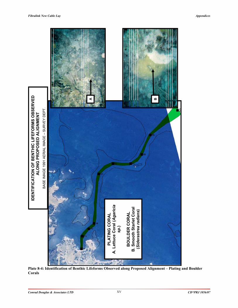
Fibralink New Cable Lay Appendices
Conrad Douglas & Associates LTD CD*PRJ 1056/07 XV
Plate 8-4: Identification of Benthic Lifeforms Observed along Proposed Alignment – Plating and Boulder
Corals
IDE
NT
IFIC
AT
ION
OF
BE
NT
HIC
LIF
EF
OR
MS
OB
SE
RV
ED
AL
ON
G P
RO
PO
SE
D A
LIG
NM
EN
T
BA
SE
IM
AG
E 1
991 A
ER
IAL I
MA
GE
–S
UR
VE
Y D
EP
T.
BA
PL
AT
ING
CO
RA
L
A.
Le
ttu
ce
Co
ral
(Ag
ari
cia
sp
.)
BO
UL
DE
R C
OR
AL
B.
Sm
oo
th S
tarl
et
Co
ral
(Sid
era
str
ea
rad
ian
s)

Fibralink New Cable Lay Appendices
Conrad Douglas & Associates LTD CD*PRJ 1056/07 XVI
Plate 8-5: Mobile Lifeform Observed along Proposed Alignment
MO
BIL
E
LIF
EF
OR
MS
OB
SE
RV
ED
AL
ON
G P
RO
PO
SE
D
AL
IGN
ME
NT
IMA
GE
S O
BT
AIN
ED
FR
OM
TH
E W
EB
.
a.
Se
rge
an
t M
ajo
r
b.
Du
sk
y D
am
se
lfis
h
c.
Blu
eh
ea
d W
ras
se
MO
BIL
E
LIF
EF
OR
MS
OB
SE
RV
ED
AL
ON
G P
RO
PO
SE
D
AL
IGN
ME
NT
IMA
GE
S O
BT
AIN
ED
FR
OM
TH
E W
EB
.
a.
Se
rge
an
t M
ajo
r
b.
Du
sk
y D
am
se
lfis
h
c.
Blu
eh
ea
d W
ras
se

Fibralink New Cable Lay Appendices
Conrad Douglas & Associates LTD CD*PRJ 1056/07 XVII
Plate 8-6: Identification of Benthic Lifeforms Observed along the Proposed Alignment - Waypoint 2
IDE
NT
IFIC
AT
ION
OF
BE
NT
HIC
L
IFE
FO
RM
S O
BS
ER
VE
D
AL
ON
G P
RO
PO
SE
D A
LIG
NM
EN
T -
wa
yp
oin
t 2
.
BA
SE
IM
AG
E 1
991 A
ER
IAL I
MA
GE
–S
UR
VE
Y D
EP
T.
2
2
SE
AG
RA
SS
A.
Tu
rtle
Gra
ss
(T
ha
las
sia
Te
stu
din
um
) B
. M
an
ate
e
Gra
ss
(S
yri
ng
od
ium
fili
form
e)
BA
Su
bs
tra
te –
So
ft C
arb
on
ate
Se
dim
en
t
Lif
efo
rm –
Sea
gra
ss
DA
FO
R –
De
ns
e

Fibralink New Cable Lay Appendices
Conrad Douglas & Associates LTD CD*PRJ 1056/07 XVIII
Plate 8-7: Identification of Benthic Lifeforms Observed along the Proposed Alignment - Waypoint 8 & 9
SU
BS
TR
AT
ES
/ B
EN
TH
IC L
IFE
FO
RM
S O
BS
ER
VE
D A
LO
NG
PR
OP
OS
ED
AL
IGN
ME
NT
wa
yp
oin
ts 8
& 9
BA
SE
IM
AG
E 1
991 A
ER
IAL I
MA
GE
–S
UR
VE
Y D
EP
T.
8
98
9
Su
bs
tra
te –
Hard
Ca
rbo
na
te
Lif
efo
rm –
Alg
ae
DA
FO
R –
Ab
un
da
nt
Lif
efo
rm –
Co
ral
(A)
DA
FO
R -
Oc
ca
sio
na
l
A
SU
BS
TR
AT
ES
/ B
EN
TH
IC L
IFE
FO
RM
S O
BS
ER
VE
D A
LO
NG
PR
OP
OS
ED
AL
IGN
ME
NT
wa
yp
oin
ts 8
& 9
BA
SE
IM
AG
E 1
991 A
ER
IAL I
MA
GE
–S
UR
VE
Y D
EP
T.
8
98
9
Su
bs
tra
te –
Hard
Ca
rbo
na
te
Lif
efo
rm –
Alg
ae
DA
FO
R –
Ab
un
da
nt
Lif
efo
rm –
Co
ral
(A)
DA
FO
R -
Oc
ca
sio
na
l
A


![[2020] JMCA Civ 35 JAMAICA IN THE COURT OF APPEAL … · 2020-07-31 · Limited (Traille) and the respondent, Cable & Wireless Jamaica Limited t/a LIME (CWJ). The application of the](https://static.fdocuments.net/doc/165x107/5f91868393871e094772ee01/2020-jmca-civ-35-jamaica-in-the-court-of-appeal-2020-07-31-limited-traille.jpg)