
MARINE AND OFFSHORE CABLES - construmatica.com · The following list of IEC standards are the basis...
126
CABLES PARA INDUSTRIA NAVAL CABLES PARA INDUSTRIA NAVAL CABLES PARA INDUSTRIA NAVAL MARINE AND OFFSHORE CABLES MARINE AND OFFSHORE CABLES MARINE AND OFFSHORE CABLES
Transcript of MARINE AND OFFSHORE CABLES - construmatica.com · The following list of IEC standards are the basis...

C A B L E S P A R A I N D U S T R I A N A V A LC A B L E S P A R A I N D U S T R I A N A V A LC A B L E S P A R A I N D U S T R I A N A V A L
M A R I N E A N D O F F S H O R E C A B L E SM A R I N E A N D O F F S H O R E C A B L E SM A R I N E A N D O F F S H O R E C A B L E S

PRESENTACIÓNFOREWORD
1
Una de las mayores compañías delsector a nivel mundial.
General Cable es una compañía líder en la fabrica-
ción de cables a nivel mundial. La compañía cuenta
con modernas instalaciones de producción en
Norteamérica, Europa y Oceanía, dando empleo a
más de 6.000 personas en todo el mundo.
Con una tradición centenaria, General Cable es una
de las compañías históricas del sector y con su acti-
vidad ha contribuido y contribuye decisivamente al
progreso de la sociedad y a la mejora de la calidad
de vida de las personas.
La gama de cables de General Cable es muy amplia
y comprende desde cables de energía a cables de
telecomunicaciones, pasando por cables eléctricos,
para construcción, transmisión de datos, instrumen-
tación, control y especiales, así como cables de Alta
Tensión. Las ventas de la compañía se distribuyen a
todo el mundo, sobre la base de las tres grandes
regiones geográficas: Norteamérica, Europa y
Oceanía.
La estrategia de General Cable se basa en tres prin-
cipios fundamentales: The Power of One (la capaci-
dad de convertirse en un proveedor que satisfaga
todas las necesidades de sus clientes), un excelente
servicio a dichos clientes y una mejora continua de la
productividad.
Asimismo, General Cable basa su actividad en una
serie de valores corporativos que guían todas sus
operaciones: la satisfacción del cliente como priori-
dad absoluta, la integridad en todos los actos, con-
siderar a las personas como la principal fuente de
valor, el trabajo en equipo como camino a la exce-
lencia, la rapidez en la entrega como ventaja compe-
titiva y la mejora continua como objetivo constante.
One of the world’s biggest companies inthe sector.
General Cable is a world leader in cable manufacture.
The company has modern production facilities in North
America, Europe and Oceania, employing more than
6,000 people throughout the world.
With a tradition lasting a hundred years, General Cable
is one of the big historical companies of the sector, and
through its activity it has contributed and still contribu-
tes decisively to the progress of society and to the
improvement of the quality of life of people.
General Cable’s range of cables is very broad and goes
from energy to telecommunication cables, including
electric, construction, data transmission, instrumenta-
tion, control and special cables, as well as high voltage
cables. The sales of the company are distributed
throughout the world, based on the three large geo-
graphic regions:
North America, Europe and Oceania.
General Cable’s strategy is based on three main princi-
ples: The Power of One (the capacity to become a sup-
plier which meets all the needs of its customers), an
excellent service for these customers and continuous
improvement of productivity.
General Cable likewise bases its activities on a series of
corporate values which guide all of its operations: cus-
tomer satisfaction as an absolute priority; integrity in all
of its actions; considering people as the main source of
value; teamwork as a path to excellence; speed of deli-
very as a competitive advantage; and continuous
improvement as a constant objective.


3
ÍNDICEINDEX
SÍMBOLOS / SYMBOLS 4
INTRODUCCIÓN / INTRODUCTION 6
CABLES PARA BUQUES MARINE CABLES
Información técnica. / Technical information 25
Guía de selección cables / Selection guide 31
Cables para buques / Marine cables 32
CABLES PARA PLATAFORMAS OFFSHORE CABLES
Información técnica / Technical information 69
Guía de selección cables / Selection guide 76
Cables para plataformas / Offshore cables 78
General Cable se reserva el derecho de alterar o modificar las especificaciones a la luz de futuros desarrollos técnicos.
General Cable reserves the right to alter or modify specifications and materials in the light of later technical development.

4
SÍMBOLOSSYMBOLS
- NO PROPAGACIÓN DE LA LLAMA - IEC 60332-1- FLAME RETARDANT SINGLE WIRE - IEC 60332-1
- NO PROPAGACIÓN DEL INCENDIO - IEC 60332-3-24- FLAME RETARDANT BUNCHED WIRES - IEC 60332-3-24
- RESISTENTE AL FUEGO - IEC 60331- FIRE RESISTANT - IEC 60331-21
- BAJA EMISIÓN DE HUMOS - IEC 61034-2- LOW SMOKE EMISSION - IEC 61034-2
- BAJA EMISIÓN DE HUMOS TÓXICOS - RATP K20- LOW TOXIC FUME EMISSION - RATP K20 RATP K20
- BAJA EMISIÓN DE GASES CORROSIVOS - IEC 60754-1-2- LOW CORROSIVE FUME EMISSION - IEC 60754-1-2
- PROTECCIÓN MECÁNICA CONTRA ROEDORES- MECHANICAL PROTECTION AGAINST RODENTS
- ALTA FLEXIBILIDAD- INCREASED FLEXIBILITY
- RESISTENCIA MECÁNICA- MECHANICAL RESISTANCE
- SERVICIOS DUROS- HEAVY DUTY
- RESISTENCIA A LA INTEMPERIE- WEATHERING TEST RESISTANT

5
- RESISTENCIA A LOS ACEITES MINERALES- MINERAL OIL RESISTANCE
- RESISTENCIA A LOS HIDROCARBUROS- HYDROCARBON RESISTANCE
- REDUCIDO RADIO DE CURVATURA- REDUCED BENDING RADIUS
- PROTECCIÓN FRENTE A LAS INTERFERENCIAS ELECTROMAGNÉTICAS- ELECTRO-MAGNETIC INTERFERENCE PROTECTION
- ESTANCO- WATERTIGHT
- RESISTENCIA A LOS FANGOS- MUD OIL RESISTANCE

ABS BUREAU VERITAS DET NORSKE VERITAS
LLOYD’S REGISTER R.I.N.A. GERMANISCHER LLOYD
6
I N T R O D U C C I Ó NI N T R O D U C T I O N
CABLES INDUSTRIA NAVALGeneral Cable presenta en este catálogo, sus series decables navales para distribución y control de energía eninstalaciones fijas en los buques y plataformas petrolíferas.
Como novedad en este sector se presentan las series decables con conductor flexible para instalación fija a fin defacilitar el tendido e instalación.
Los diseños de cables descritos en el presente catálogose han realizado de acuerdo con las siguientes normas yespecificaciones.
MARINE CABLESGeneral Cable presents in its catalogue its series of navalcables for the distribution and control of energy in fixed ins-tallations on ships and offshore units.
A new development in this sector is the series of cableswith flexible conductor for fixed installation in order to aidthe laying and installation.
The designs of the cables described in this catalogue werecarried out in accordance with the following standards andspecifications.
UNE 21135-350 (IEC 60092-350)
“Instalaciones eléctricas en buques”
UNE 21022 (IEC 60228)
“Conductores de cables aislados”
UNE-EN 50266-2-2 (IEC 60332-3-22 cat.A)
“Ensayo de propagación vertical de la llama de cablescolocados en capas en posición vertical. Categoría A”
UNE 20431 (IEC 60331-21)
“Características de los cables eléctricos resistentes alfuego”
UNE-EN 50267-1 (IEC 60754-1)
“Ensayos de los gases desprendidos durante la combus-tión de materiales procedentes de los cables”
UNE-EN 50267-2 (IEC 60764-2)
“Determinación del grado de acidez de gases de losmateriales por medida del pH y la conductividad”
UNE-EN 50268 (IEC 61034-2)
“Medida de la densidad de los humos emitidos porcables en combustión bajo condiciones definidas”
IEC 60092-350
(International Electrotechnical Commission) “Electrical ins-tallations in ships”
IEC 60228
“Conductors of insulated cables”
IEC 60332-3-22 cat. A
“Tests on bunched electric cables under fire conditions,“Fire retardant”.
IEC 60331-21
“Fire-resisting characteristics of electric cables”
IEC 60754-1
“Determination of the amount of halogen acid gas”
IEC 60754-2
“Determination of degree of acidity of gases”
IEC 61034-2
“Measurement of smoke density”
Los cables del presente catálogo estan amparados conAprobaciones de Tipo de las principales sociedades deClasificación:
Cables shown in this cataloge are covered with “TypeApprovals” from main classification societies:
7
ESPECIFICACIONES DE DISEÑOLos cables para industria naval detallados en este catá-logo, están diseñados de acuerdo con las normas IECsiguientes:
DESIGN SPECIFICATIONSThe following list of IEC standards are the basis for thedesing of the marine cables detailed in this catalogue:
UNE 21135-350 (IEC 60092-350)
“Construcción general y requisitos de ensayo”
UNE 21135-351 (IEC 60092-351)
“Materiales de aislamientos para cables”
UNE 21135-352 (IEC 60092-352)
“Elección e instalación de cables para redes de baja tensión”
UNE 21135-353 (IEC 60092-353)
“Cables unipolares y multipolares de campo no radialcon aislamiento seco extruido para tensiones de 1 kV y 3 kV”
UNE 21135-354 (IEC 60092-354)
“Cables de energia unipolares y tripolares con aislamien-to seco extruido para tensiones de 6 kV, 10 kV y 15 kV”
UNE 21139-359 (IEC 60092-359)
“Materiales de cubierta para cables”
IEC 60092-376
“Cables para circuitos de control e instrumentación150/250 V (300V)”
IEC 60092-350
“General construction and test requirements”
IEC 60092-351
“Insulating materials for shipboard”
IEC 60092-352
“Choice and installation of cables for low voltage powersystems”
IEC 60092-353
“Single and multicore non-radial field power cables withextruded solid insulation for rated voltage 1 kV and 3 kV”
IEC 60092-354
“Single and three-core power cables with extruded solidinsulation for rated voltages 6 kV up to 30 kV”
IEC 60092-359
“Sheathing materials for shipboard”
IEC 60092-376
“Cables for control and instrumentation circuits 150/250 V(300 V)”

8
SERVICIOEn función de su utilización, los cables se distribuyen enlos siguientes grupos:
CABLES DE POTENCIA DE BAJA TENSIÓN (IEC 60092-353)
- Cables para distribución de energía a 0,6/ 1 kV.
- Composiciones hasta 4 conductores. Identificación por coloración del aislamiento.
- Composiciones con 5 hasta 37 conductores. Identificación por numeración.
CABLES DE POTENCIA DE MEDIA TENSIÓN(IEC 60092-354)
- Cables para distribución de energía en tensiones de6 a 30 kV.
CABLES DE CONTROL (IEC 60092-376)
- Cables para control a 250 V
- Composición de 2 a 37 conductores. Identificación por numeración.
- Apantallado colectivo con cinta de aluminio poliéstery drenaje.
- Armado y apantallado colectivo con trenza de cobre.
CABLES DE INSTRUMENTACIÓN (IEC 60092-376)
- Cables de pares o tríos para instrumentación a 250 V.
- Conductores identificados por color y cinta numerada en cada par.
- Cable de dos pares sin pantalla individual, tiene formación de cuadrete / estrella
- Apantallado colectivo (cinta de Al/poliéster y drenaje)o individual y colectivo (cinta Al/poliéster y drenaje encada par).
- Para cables de instalaciones offshore (NEK 606), apantallado colectivo (trenza de cobre) o individual ycolectiva (cinta Cu / poliéster y drenaje en cada pary trenza de cobre colectiva).
USESDepending on their use, the cables are distributed into thefollowing groups:
LOW VOLTAGE POWER CABLES (IEC 60092-353)
- Power cables suitable for operation at up to and including 0.6/1 kV.
- Constructions up to and including 4 core. Coloured core identification.
- Constructions with 5 to 37 core. Numbered core identification.
MEDIUM VOLTAGE CABLES (IEC 60092-354)
- Cables for distribution of energy in voltages of 6 to 30 kV.
CONTROL CABLES (IEC 60092-376)
- Suitable for operation up to and including 250 V.
- Available from 2 to 37 cores. Identification by numbering.
- Collective screen with Al/polyester tape and drain wire.
- Armoured and collective screen with copper wire braid.
INTRUMENTATION CABLES (IEC 60092-376)
- Multiunit (pairs or triple core) cables suitable for operation up to and including 250 V.
- Cores identified by colours and numbered tape in eachunit.
- Two pair cable without individual screen has a star/quad composition.
- Collective screening (Al/polyester tape and draun wire)or individual and collective (Al/polyester tape and drainwire in each unit).
- Armoured and collective screen with copper braid.
- For offshore cables (NEK 606), collective screening (copper braid) or individual and collective (Cu/polyestertape and drain wire in each unit and collective copperbraid),

9
COMPOSICIÓNEn base a las normas IEC citadas anteriormente, yhaciendo un repaso a la formación de los cables tene-mos:
ConductorDe cobre recocido según IEC 60228:
Clase 2: Conductores rígidos de formación 7 hilos (ensecciones pequeñas) o coronas concéntricas para sec-ciones mayores.
Clase 5: Conductores flexibles de formación multifilar.
En general se utilizan los de clase 2, pero está aumen-tando el uso de los de clase 5 por su manejabilidad y portanto mayor facilidad de instalación.
Para instalaciones offshore, el conductor se utiliza esta-ñado para dar una mayor protección de las conexionesfrente a las oxidaciones en los ambiente marinos duros.
Para secciones y composiciones normalizadas a utilizar,ver cuadros siguientes:
CONSTRUCTIONOn the basis of the above-mentioned IEC standards, andreviewing the formation of the cables, we have:
ConductorAnnealed copper in accordance with IEC 60228:
Class 2: Rigid conductors with 7 wire formation (in smallsections) or concentric layers in big cross sections.
Class 5: Flexible conductors bunched or multibunchedconfigurations.
In general those of class 2 are used, but the use of class 5is growing, due to their handeability and therefore their gre-ater ease of installation.
In offshore industry, tin plated conductor is used to offergreater protection of conections against oxidation in heavymarine environments.
See the following tables for standarized sections and com-positions to be used:
Tipo cable Tensión Sección conductor Norma IEC
Cable type Voltage grade Area of conductor IEC StandardkV mm2
Potencia Baja Tensión 1 kV 1,5 ÷ 300 mm2
Power Low Voltage 3 kV 10 ÷ 300 mm2 60092-353
Control e instrumentación
Control and instrumentation 250 V 0,50 ÷ 2,50 60092-376
Potencia Media Tensión 6 kV 10 ÷ 630 mm2
Power Medium Voltage 10 kV 16 ÷ 630 mm2
15 kV 25 ÷ 630 mm2 60092-354
20 kV 35 ÷ 630 mm2
Secciones / Cross sectional area

10
Insulation materialsIn IEC 60092-351 standard there are six generic insulation,but as four of them can be produced in halogen free (HF)version, in tables appears ten compounds.
PVC (Polyvinyl chloride). This is a thermoplastic materialwhich is distorted by heat (as insulation it has fallen intodisuse, giving way to crosslinked polyethylene). At low tem-peratures it hardens and can even crack if has not beenspecifically designed.
EPR (Ethylene propylene). A thermosetting elastomer, ithas an almost nil distortion due to the action of heat. Itgives the cable greater flexibility. Especially suitable if thesheath has to be a crosslinked compound.
HEPR (Hard grade etylene propylene.) Improved EPRcompound bringing beter performance both in mechanicalo electrical properties. This brings to a thickness insulationssimilars to the XLPE ones.
Materiales de aislamientoEn la norma IEC 60092-351 aparecen seis tipos de aisla-miento genérico, sin embargo cuatro de ellos, puedenproducirse además en versión libre de halógenos (HF), loque conduce a diez tipos distintos.
PVC (Policloruro de vinilo). Material termoplástico, defor-mable con el calor, (como aislamiento está en desuso,está siendo sustituido por el polietileno reticulado). Abajas temperaturas se endurece y puede llegar a cuarte-arse si no se utilizan compuestos específicos.
EPR (Etileno propileno). Elastómero termoestable, defor-mación casi nula por la acción del calor. Confiere mayorflexibilidad al cable. Especialmente indicado si la cubier-ta debe ser de compuesto termoestable.
HEPR (Etileno propileno de alto módulo). Variante decompuesto de EPR que ofrece unas mejores propieda-des eléctricas y mecánicas. Esta mejora se refleja en suequiparamiento dimensional con el polietileno reticula-do.
Tipo cable Número de conductores Norma IECCable type Number of cores IEC Standard
Potencia B.T. “N” (No se fijan)
Power L.V. “N” (Not specified) 60092-353
Cables de control 2,4,7,12,19,27,37 conductores
Control cables 2,4,7,12,19,27,37 cores 60092-376
Instrumentación 1,2*, 4,7,10,14,19,24,30,37 pares
Instrumentation 1,2*, 4,7,10,14,19,24,30,37 pairs 60092-376
Potencia M.T. 1 ÷ 3 conductores
Power M.V. 1 ÷ 3 cores 60092-354
(*) El cable de dos pares tiene una formación de cuadrete/estrella, utilizándose los conductores diametral-mente opuestos para formar los dos pares.
(*) Two pair cable is a star-quad composition, cores diametrally oposed are used to conform the pairs.
Composición nº conductores / Composition number of cores

11
XLPE (Polietileno reticulado). Material termoestable,deformación reducida con la temperatura. Muy buenaspropiedades eléctricas y mecánicas, admite que losespesores sean menores que el EPR.
SILICONA. Elastómero especial para trabajar a altastemperaturas en utilizaciones muy específicas. Pocaaplicación en la industria naval.
HF 85 (poliolefina reticulada). Compuesto de poliolefinapara aplicaciones especiales.
XLPE (Crosslinked polyethylene). A heatstable material,very little distortion with temperature. Very good electricaland mechanical properties.
SILICONE. A special elastomer to work at high temperatu-res for very specific uses. Little application in the navalindustry.
HF 85 (cross-linked polyolefin). Cross-linked polyolefin forspecial uses.
Tipo de compuesto de aislamiento Designación abreviada Máxima temperatura Conductor °C
Operación Normal Cortocircuito
a) Termoplástico
Basado en cloruro de polivinilo o un copolímero de cloruro de vinilo y vinilacetato PVC 70 150
b) Elástométrico o termoestable
basado en caucho etileno propileno o similar (EPM o EPDM) EPR 90 250
basado en caucho etileno propileno de alto módulo o alto grado HEPR 90 250
basado en polietileno reticulado XLPE 90 250
basado en caucho de silicona S 95 95 350
basado en caucho etileno propileno o similar(EPM o EPDM) libre de halógenos HF EPR 90 250
basado en caucho etileno propileno de alto módulo o alto grado libre de halógenos HF HEPR 90 250
basado en polietileno reticulado libre dehalógenos. HF XLPE 90 250
basado en caucho de silicona libre de halógenos HF S 95 95 350
basado en poliolefina reticulada para cable libres de halógenos HF 85 85 250
Materiales de aislamiento

12
Type of insulating compound Abbreviated designation Maximum rated conductor Temperature °C
Normal Operation Short-circuit
a) Thermoplastic
based upon polyvinyl chloride or copolymer of vinyl chloride and vinyl acetate PVC 70 150
b) Elastomeric or thermoset:
based upon ethylene-propylene rubber or similar (EPM or EPDM) EPR 90 250
based upon high modulus or hard grade ethylene propylene rubber HEPR 90 250
based upon cross-linked polyethylene XLPE 90 250
based upon silicone rubber S 95 95 350
based upon ethylene-propylene rubber or similar (EPM o EPDM) Halogen free HF EPR 90 250
based upon high modulus of hard grade halogen free ethylene propylene rubber HF HEPR 90 250
based upon Halogen free cross-linked polyethylene HF XLPE 90 250
based upon Halogen free silicone rubber HF S 95 95 350
based upon cross-linked polyolefin material for Halogen free cables HF 85 85 250
Insulation materials
Materiales de cubiertaLas cubiertas de los cables protegen al conjunto de losconductores aislados de las agresiones mecánicas oambientales que puedan sufrir. Las agresiones mecánicasson principalmente abrasiones por arrastre en los con-ductos y se producen durante la instalación, mientras quelas ambientales (calor, presencia de aceites o agentesagresivos) afectarán al cable durante toda su vida útil.
PVC. Se describen dos tipos de compuesto termoplásti-co, uno para 60° (ST1) y otro para 85°C (ST2) de tempe-ratura de servicio del conductor. Presenta buena resisten-cia mecánica y a los disolventes. La resistencia frente alos aceites y combustibles es pobre.
Sheathing materialsThe sheath of the cables protects the set of cores from themechanical or environmental aggressions they can suffer.Mechanical aggressions are mainly abrasions from thedragging of the cables and tears at angles of the tubes andoccur during the installation, while the environment aggres-sions (heat, presence of oils or aggressive agents) willaffect the cable throughout its working life.
PVC. Two types of thermoplastic compound are described,one for 60° (ST1) and the other for 85°C (ST2) service tem-perature of the conductor. It presents good mechanicalresistance and resistance to solvents. The resistance to oilsand fuel is poor.
13
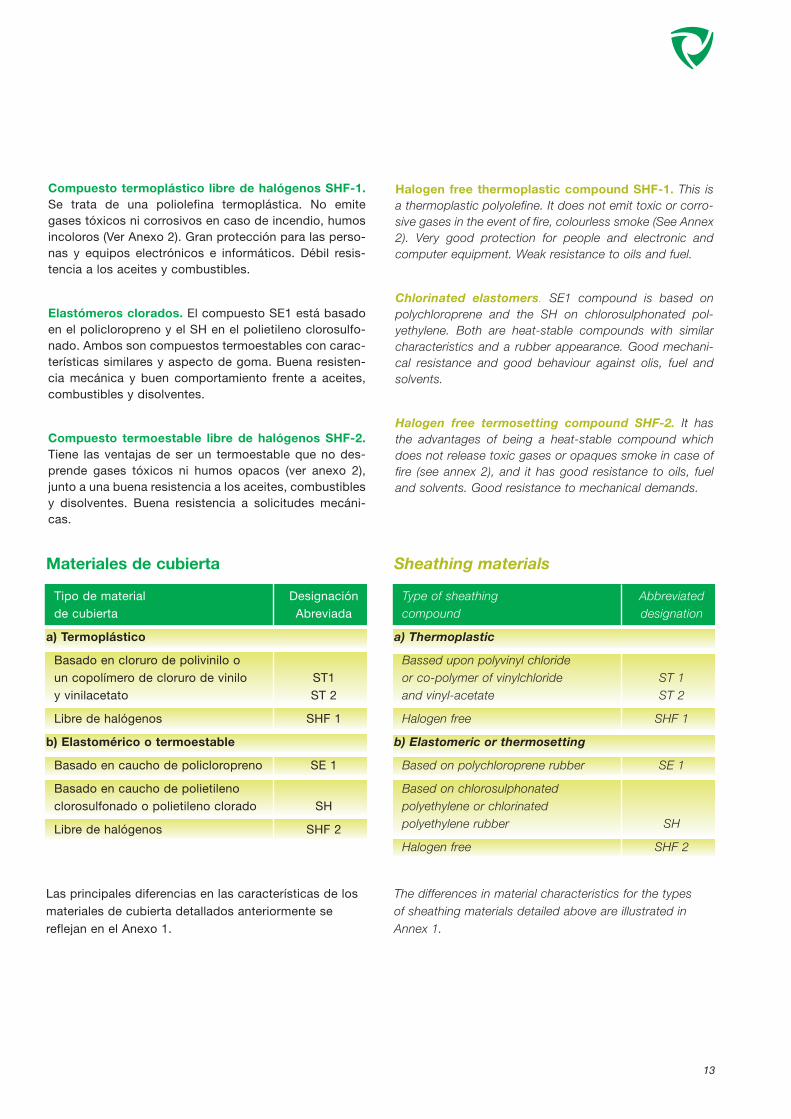
Compuesto termoplástico libre de halógenos SHF-1.Se trata de una poliolefina termoplástica. No emitegases tóxicos ni corrosivos en caso de incendio, humosincoloros (Ver Anexo 2). Gran protección para las perso-nas y equipos electrónicos e informáticos. Débil resis-tencia a los aceites y combustibles.
Elastómeros clorados. El compuesto SE1 está basadoen el policloropreno y el SH en el polietileno clorosulfo-nado. Ambos son compuestos termoestables con carac-terísticas similares y aspecto de goma. Buena resisten-cia mecánica y buen comportamiento frente a aceites,combustibles y disolventes.
Compuesto termoestable libre de halógenos SHF-2.Tiene las ventajas de ser un termoestable que no des-prende gases tóxicos ni humos opacos (ver anexo 2),junto a una buena resistencia a los aceites, combustiblesy disolventes. Buena resistencia a solicitudes mecáni-cas.
Halogen free thermoplastic compound SHF-1. This isa thermoplastic polyolefine. It does not emit toxic or corro-sive gases in the event of fire, colourless smoke (See Annex2). Very good protection for people and electronic andcomputer equipment. Weak resistance to oils and fuel.
Chlorinated elastomers. SE1 compound is based onpolychloroprene and the SH on chlorosulphonated pol-yethylene. Both are heat-stable compounds with similarcharacteristics and a rubber appearance. Good mechani-cal resistance and good behaviour against olis, fuel andsolvents.
Halogen free termosetting compound SHF-2. It hasthe advantages of being a heat-stable compound whichdoes not release toxic gases or opaques smoke in case offire (see annex 2), and it has good resistance to oils, fueland solvents. Good resistance to mechanical demands.
Materiales de cubierta
Tipo de material Designaciónde cubierta Abreviada
a) Termoplástico
Basado en cloruro de polivinilo o un copolímero de cloruro de vinilo ST1y vinilacetato ST 2
Libre de halógenos SHF 1
b) Elastomérico o termoestable
Basado en caucho de policloropreno SE 1
Basado en caucho de polietileno clorosulfonado o polietileno clorado SH
Libre de halógenos SHF 2
Las principales diferencias en las características de losmateriales de cubierta detallados anteriormente sereflejan en el Anexo 1.
Sheathing materials
Type of sheathing Abbreviated compound designation
a) Thermoplastic
Bassed upon polyvinyl chloride or co-polymer of vinylchloride ST 1and vinyl-acetate ST 2
Halogen free SHF 1
b) Elastomeric or thermosetting
Based on polychloroprene rubber SE 1
Based on chlorosulphonated polyethylene or chlorinated polyethylene rubber SH
Halogen free SHF 2
The differences in material characteristics for the types of sheathing materials detailed above are illustrated inAnnex 1.

14
ArmadurasLas armaduras aportan protección mecánica al cable. Enla industria de construcción naval, la armadura que se havenido empleando es la de trenza de hilos de acero, sinembargo esta construcción no es válida para los cablesunipolares de potencia de sección superior a 16 mm2 yaque debe utilizarse un material amagnético, utilizándoseen este caso el cobre en versión estañada o desnudo.Dado que la norma admite que el material para armadu-ra puede ser cobre, la tendencia actual va en la direcciónde utilizar trenzas de cobre también en los cables devarios conductores.
La utilización de cobre en la armadura ejerce una doblefunción ya que se comporta como armadura pero tam-bién como pantalla.
PantallasEn los cables de baja tensión, las pantallas son los ele-mentos que aportan protección al cable frente a loscampos eléctricos y electromagnéticos de alta frecuen-cia. Es un elemento especialmente indicado para cablesde instrumentación, control y transmisión de señales porsu sensibilidad a las radiaciones que pueden distorsio-nar la señal transmitida por el cable. Para proteger elcable de las radiaciones hay que apantallar el conjuntode los conductores (protección de perturbaciones exte-riores) o cada uno de los pares o tríos (campos electro-magnéticos provinientes de otros elementos del mismocable).
ArmouringThe armour gives the cable mechanical protection. In mari-ne industry, the armour traditionally used was the steel wirebraid, but this construction is not, however, suitable forpower single core cables with crossectional area langerthan 16 mm2 as a nonmagnetic material must be used, thecopper in tinplated or bare version being used in this case.Given that the standard accepts that the armouring mate-rial can be copper, the current trend is also going towardthe use of copper braids in cables with several conductors.
The use of copper in the armour performs a dual functionas it behaves as armour but also as a screen.
ScreeningIn low tensión cables, the screens are the elements whichprovide the cable protection against electromagnetic fields.This is an element especially suitable for cables for instru-mentation, control and transmission of signals thanks to itssensitivity to radiation which can distort the signal transmit-ted by the cable. To protect the cable from radiation it isnecessary to screen the group of conductors (protectionfrom external disturbance) or each one of the pairs or tri-ples (electromagnetic fields from other elements of thesame cable).
Armaduras / Armouring materials
TipoType Materiales Materials
TRENZA - Acero galvanizado - Galvanized steel
- Cobre recocido desnudo - Plain annealed copper
BRAID - Cobre recocido estañado - Tinned annealed copper
- Bronce - Bronze

15
Según la norma, las pantallas pueden ser de trenza decobre o bien de cinta de metal/poliéster, siendo la partemetálica de aluminio o de cobre.
En los cables que requieren armadura, la utilización dearmadura de trenza de cobre hace que estando debida-mente colocadas a tierra, pueda ser utilizada para tam-bién como pantalla del cable.
Compatibilidad Electromagnética (EMC)Los productos de General Cable cumplen los requeri-mientos sobre Compatibilidad Electromagnética siempreque en su instalación se hayan respetado las condicio-nes establecidas en la norma IEC 60533.
According to the standard, screens can be either braid orlaminated tape, with metallic part beeing aluminium or cop-per.
In armoured type cables, the use of copper wire braidarmour, when properly earthed, allows to use it as a collec-tive screen.
Electromagnetic compatibility (EMC)When General Cable products are installed in accordancewith IEC 60533, they fulfil the requirements for Electro-Magnetic Compatibility.
Pantallas / Screening materials
TipoType Materiales Materials
TRENZA - Cobre recocido desnudo - Plain annealed copper
BRAID - Cobre recocido estañado - Tinned annealed copper
CINTA - Al/poliéster - Al/polyester
TAPE - Cu/poliéster - Cu/polyester

16
Comportamiento de los cables en casode fuegoA fin de determinar el comportamiento de los cables anteuna situación de incendio, se han desarrollado una seriede normas, las cuales definen unas condiciones de fuegoy miden el comportamiento del cable en esta situación,sin embargo, debe tenerse en cuenta que estos ensayossirven para valorar el comportamiento de los cables enunas condiciones establecidas y reproducibles y que nonecesariamente son las de la instalación a bordo.
La normativa IEC actual contempla los siguientes casos:
- No propagación de la llama (Norma IEC 60332-1).
Una llama en contacto con lacubierta del cable durante un tiem-po establecido no debe provocar sucombustión. Así se evita que elcable sea origen de un incendioocasionado por un incidente demenor entidad o una fuente de calorexterior que por error entre en con-tacto con el cable.
- No propagación del incendio(Norma IEC 60332-3).
Un incendio ajeno al cable puedeafectar una canalización (agraván-dose si está en posición verticalque permita circulación de aire cre-ando el llamado efecto chimenea).Si se alcanza la temperatura dedescomposición de los materialesorgánicos, se produce una combus-tión exotérmica (con aporte deenergía) de los cables y la consi-guiente propagación del incendio.Los compuestos de aislamiento ycubierta se pueden formular de talforma que dificulten dicha reacciónexotérmica (mediante adición deinhibidores). Para simular tal situa-ción, la prueba consiste en la apli-cación de un quemador de gas degran potencia a un mazo de cablesdispuestos de tal forma que repro-ducen una canalización vertical conaire forzado. En estas condiciones,el incendio provocado en los cablesdebe autoextinguirse en un tiempoestablecido en la norma.
Perfomace of cables in the event of fireIn order to determine the behaviour of cables in case offire, a group of standards has been developed in order tostablish conditions of fire and to chek the behaviour of thecable in this situation, but it should be taken into accountthat those tests are used to assess the behaviour of thecables under established, reproducible conditions andthat they are nor necessarily those of the on-board insta-llation.
The current IEC regulation consider the following cases:
- Flame retardant (Standard IEC 60332-1).
A flame in contact with the sheath ofthe cable for an established period oftime should not lead to combustion.This prevents the cable from beingthe origin of a fire caused by a minorincident or an external source of heatwhich due to error comes into con-tact with the cable.
- Flame spread (Standard IEC60332-3).
A fire unrelated to the cable canaffect a conduit (beeing worst if it isin vertical position allowing air circu-lation creating the so-called chimneyeffect). If the decomposition tempe-rature of the organic materials is rea-ched, an exothermic combustion(with the contribution of energy) ofthe cables takes place with the con-sequent propagation of the fire. Theinsulation and sheath compoundscan be formulated to make this exot-hermic reaction difficult (by the addi-tion of inhibitors). To simulate thissituation, the test consists in theapplication of a high power gas bur-ner to a bunch of cables arranged toreproduce a vertical conduit with for-ced air. Under those conditions, thefire provoked in the cables shouldextinguish itself in a time establishedin the standard.
IEC 60332-1

17
En función del volumen de material combustible pormetro lineal de mazo expuesto a la acción del fuego, enla norma se establecen cinco categorías, de las cuales,para la industria naval está prescrito que sea la CategoríaA (IEC 60332 part 3-22).
Based in the amount of combustible material per meter ofbunch exposed to the fire action, the standard defines fivedifferent categories, an according to IEC 60092-350 beingthe mandatory one for shipbuilding Category A (IEC 60332part 3-22).
IEC 60332-3-22
IEC 60332-3

18
Resistencia al fuego (Norma IEC 60331).
Para los circuitos de seguridad y aquellos elementos quedeben seguir dando servicio aún en presencia de unincendio la norma IEC 60331 define las condiciones delensayo a que se somete un cable que tiene que seguirdando servicio aunque el fuego haya destruido las par-tes orgánicas del mismo.
En el ensayo, el cable se somete a la acción de un que-mador de 750 °C durante un período de 90 minutosdurante el cual y al final del mismo, el cable debe seguirsiendo operativo.
Fire-resistant (Standard IEC 60331).
For circuit integrity and all those systems wich need to giveservice under fire conditions, there is IEC 60331 standardwhere it is defined the fire conditions to which the cables istested and which has to continue in service even if the hasdestroyed the organic parts of the same.
In the test, the cable is exposed to a ribbon gas burner for90 minutes and at 750 °C. During the test and at the endof it the cable has to be in service although all of its orga-nic parts has desappeared.
IEC 60331

19
IEC 60754
IEC 61034
Cables libres de halógenos y reducida emisión dehumos
En caso de que los cables se vean inmersos en unasituación de incendio y en función de los materiales quecomponen los mismos, pueden desprenderse gasestóxicos para la salud de las personas o corrosivos parael buen funcionamiento y estado de conservación de loscomponentes electrónicos e informáticos que seencuentren en el entorno. Asimismo, pueden despren-derse humos que por su opacidad dificulten la visión delas vías de escape de los locales afectados.
Para minimizar estos efectos, General Cable ha desarro-llado los cables de la serie Exzhellent o libres de halóge-nos, los cuales eliminan las nocivas emisiones de gaseshalogenados (IEC 60754-1 y 60754-2) y reducen deforma sustancial los humos opacos, facilitando las posi-bilidades de supervivencia (IEC 61034-2) (Ver anexo 2)
Halogen free and low smoke and fumes cables
If the cables are immersed in a situation of fire, and depen-ding on the constituent materials they can release gaseswhich are toxic for the health of people or corrosives affec-ting the correct operation and state of conservation of theelectronic and computer components in the vicinity. Theycan also release smoke which, due to its opacity, makes itdifficult to see the escape routes from the spaces affected.
To minimize those efects, General Cable has developed theExzhellent o halogen free series wich eliminate harmfulhalogenated emissions (IEC 60754-1 y 60754-2) and redu-ces substantially the opaque smoke emissions (IEC 61034-2) (see annex 2).

20
MATERIAL CUBIERTA METODO ENSAYO/
NORMAS UNIDADES ST2 SE1 SH SHF1 SHF2
SHEATHING MATERIAL STANDARDS UNITS Halogen Free Halogen Free
PVC PCP CSP EVA EVA
Termoplástico Termoestable Termoestable Termoplástico Termoestable
Thermoplastic Thermosetting Thermosetting Thermoplastic Thermosetting
Índice Oxígeno
Index oxigen limit ASTM-D-2863 % 22 20 28 35 36
Índice Temperatura
Temperature index ASTM-D-2863 °C 160 130 230 280 290
Emisión Halógenos EN 50267-2-1
Halogen content IEC 60754-1 % >25 20 30 <0,5 <0,5
Corrosividad (pH) EN 502267-2-2
Corrosivity index IEC 60754-2 pH < 4.3 < 4.3 < 4.3 >4.3 >4,3
Emisión Humos (Dm)
Smoke density (Dm) ASTM-662 Dm 680 900 900 180 200
CARACTERÍSTICAS MECÁNICAS DEL MATERIAL / MATERIAL MECHANICAL CHARACTERISTICS
Resistencia Tracción Inicial
Unaged Tensile Strenght IEC 60092-359 N/mm2 12,5 10,0 10,0 9,0 9,0
Alargamiento rotura Inicial
Unaged Elongation at Break % 150 300 250 120 120
Envejecimientos Térmicos en aire
Ageing in air over IEC 60092-359 7 d. @ 100°C 7 d. @ 100°C 7 d. @ 100°C 7 d. @ 100°C 7 d. @ 120°C
Resistencia Aceites
Oil Resistance IEC 60092-359 n.a. 24h @ 100°C 24h @ 100°C n.a. 24h @ 100°C
Temperatura mínima de servicio
Minimum Low Temp. Operation IEC 60811 -15 °C -30°C -30°C -25°C -40°C
COMPUESTOS DE CUBIERTA / SHEATING MATERIALS
ANEXO 1 / ANNEX 1

21
CARACTERÍSTICAS DE EMISIÓN DE HUMOS / SMOKE EMISSION CHARACTERISTICS
ANEXO 2 / ANNEX 2


CA
BL
ES
PA
RA
BU
QU
ES
/ M
AR
INE
CA
BLE
S


25
INFORMACIÓN TÉCNICA TECHNICAL INFORMATION
DESIGNACIÓN DEL CABLE
La referencia de los cables está basada en el código deletras de las tablas siguientes:
CABLES DESIGNATION
Cable designation is based in the letter code described inthe tables below:
Conductores clase 2 / Class 2 stranded conductorsMateriales Aislamiento Pantalla Cubierta interior Armadura/Pantalla Cubierta Materials Insulation Shield Inner Sheath Armour/Shield Outer Sheath
Polietileno reticulado XLPECross-linked Polyethylene XLPE R
Caucho Etileno Propileno (EPR)Ethylene Propylene Rubber (EPR) D
Pantalla del aislamiento(cables > 3kV)Insulation screen (cables >3kV) H
Cinta de metal/poliéster (Pantalla individual)Metal/polyester tape O1(individual screen)
Poliolefina termoplástica SHF1Thermoplastic polyolefin Dt
Trenza hilos de cobreCopper wire braid C4
Cinta de metal/poliéster (Pantalla colectiva)Metal/polyester tape O2(collective screen)
Poliolefina termoplástica SHF1Thermoplastic polyolefin Dt
Conductores flexibles clase 5 / Class 5 flexible conductorsPolietileno reticulado (conductor flexible clase 5) M-XCross-linked Polyethylene(flexible conductor class 5)
Poliolefina termoplástica SHF1Thermoplastic polyolefin Z
Trenza hilos de cobreCopper wire braid C
Poliolefina termoplástica SHF1Thermoplastic polyolefin Z
Para los cables resistentes al incendio (IEC 60331, se añade “-M” al final de la descripción.
In fire resistant cables (IEC 60331), “-M” is added at the end of the description.

En las denominaciones de los cables se incluye el núme-ro y sección de los conductores (NxS). Se añade el sufi-jo "+E" cuando se requiere un conductor para puesta atierra, (NxS+E). En los cables de dos o tres conductores,se usa la terminología (NxS/E) para mostrar los cables enlos cuales, se puede utilizar la trenza de cobre comoconductor de tierra. En este caso, la sección de la tren-za es igual o superior al 50% de los conductores de fase.
26
The cable designation also includes the number and size ofcores (NxS), when an earth core is required, the suffix "+E"is used, (NxS+E). In 2 and 3 core cables, the NxS/E termi-nology is used to illustrate the cables in wich the copperwire braid armour can be employed as the earth conduc-tor. In this case, the cross sectional area of the braid isequal or greater than 50% of the phase conductors.
INTENSIDADES ADMISIBLESLas intensidades admisibles que aparecen en este catá-logo, están de acuerdo con la tabla 5 de la norma IEC60092-352 basada en una temperatura de trabajo delconductor de 90º C y temperatura ambiente de 45º C.Los valores especificados están basados en las condi-ciones de instalación siguientes,
- Cables multiconductores instalados al aire, método de instalación E.
- Conductores unipolares en contacto al aire, formación trébol método de instalación F.
En la norma IEC 60092-352, se especifican los factores aaplicar para temperaturas distintas a las citadas, otrostipos de instalación o agrupamientos de cables.
CURRENT CARRYING CAPACITIESThe current ratings stated in this catalogue are in com-pliance with IEC 60092-352 Table 5, based upon a maxi-mum conductor operating temperature of 90º C, and anambient temperature of 45º C. The specified ratings arebased upon the following installation conditions,
- Multicore cables in free air installation, method E.
- Single core cables touching, in trefoil configuration,installation method F.
De-rating factors for differing methods of installation, andambient temperatures are specified in IEC 60092-352.
TOLERANCIAS DIÁMETRO EXTERIOR / CABLE OVERALL DIAMETER TOLERANCE
Tolerancia mm Tolerance mm
Diámetro exterior nominal mm Baja tensión Media tensión
Nominal overall diameter mm Low voltage Medium voltage
< 20 -0.50 + 1.0 -0.50 +1.0
20 – 29.9 -0.50 +1.5 -0.50 +2.0
30 – 39.9 -0.75 +2.0 -0.75 +2.5
40 – 49.9 -0.75 +2.5 -0.75 +3.0
50 – 59.9 -0.75 +3.0 -0.75 +3.5
60 – 69.9 - 1.0 +3.5 - 1.0 +4.0
70 – 79.9 - 1.0 +4.0 - 1.0 +5.0
> 79.9 - 1.0 +4.5 - 1.0 +5.5

27
Superior a 1,8/3 kV - Higher than 1,8/3 kVPosición final/Final position
Unipolares
Single core
Tripolares
3 core cable
Cualquiera
Any
Cualquiera
Any
Cualquiera
Any
Cualquiera
Any
10 D
8 D
Durante el tendido / During laying up
Unipolares
Single core
Tripolares
3 core cable
Cualquiera
Any
Cualquiera
Any
Cualquiera
Any
Cualquiera
Any
20 D
16 D
RADIOS DE CURVATURA MÍNIMOS / MINIMUM BENDING RADIUS (IEC 60092-352)
Hasta 1,8/3 kV inclusive – Up to and including 1,8/3 kV
Aislamiento
Insulation
Termoplástico o termoestable
Conductores circularesde cobre.
Thermoplastic orThermosetting.
Circular copperconductors
Protección
Covering
Sin armadura ni trenza
Unarmoured or unbraided
Con armadura o pantalla detrenza metálica
Metal braid screened orarmoured
Cinta compositepoliéster/metal
apantallamiento unidades o colectivo
Composite polyester/metaltape screened units or
collective tape screening
Diámetro exteriornominal
Nominal overall diameter(D)
< 25 mm
> 25 mm
Cualquiera
Any
Cualquiera
Any
Radio Interior Curvaturamínimo
Minimum internal Radius of bend
4 D
6 D
6 D
8 D

28
Cables energía MT superior a 1,8/3 kV / MV power cables, higher than 1,8/3 kVNº conductoresNumber of cores
3 Rojo Gris NegroRed Grey Black
Cubierta roja / Red sheath
IDENTIFICACIÓN CONDUCTORES (CABLES PARA BUQUES) / CORE IDENTIFICATION(MARINE CABLE):
Cables energía hasta 1,8/3 kV inclusive/ Power cables up to and including 1,8/3 kVNº conductores Protección Fases
Number of cores Earth Phase
2 - Azul Marrón
Blue Brown - - -
2+E Amarillo-Verde Azul Marrón
Green-yellow Blue Brown - - -
3 - Azul Marrón Negro
Blue Brown Black - -
3+E Amarillo-Verde Azul Marrón Negro
Green-yellow Blue Brown Black - -
4 - Azul Marrón Negro Gris
Blue Brown Black Grey -
5 - Azul Marrón Negro Gris Negro
Blue Brown Black Grey Black
“n” - Aislamiento negro, conductores numerados
Black insulation, printed numbered cores
Cubierta negra / Black sheath

29
Cables control 250 V / Control cables 250 VNº conductoresNumber of cores
“n” Aislamiento negro, conductores numeradosBlack insulation, printed numbered cores
Cubierta gris / Grey sheath
Circuitos intrínsecamente seguros: Cubierta de color azul / Intrinsically safe circuits: Blue sheath
Cables instrumentation 250 V / Instrumentation cables 250 VConductores / Cores
Par (*) Azul NegroPair (*) Blue Black -
Trio Azul Negro MarrónTriple Blue Black Brown
Cada par o trío numerado (cinta) / Each pair or triple numbered (tape)
Cubierta gris / Grey sheath
Circuitos intrínsecamente seguros: Cubierta de color azul / Intrinsically safe circuits: Blue sheath
(*) El cable de dos pares con pantalla colectiva está cableado en cuadrete-estrella, con los conductores situados dia-metralmente opuestos: Par 1- Azul-Negro. Par 2 Marrón-Gris. / Two pairs cables collectively screened are laid up in starquad configuration with the pairs identified by diametrically opposite cores: Pair 1 - Blue and Black Cores Pair 2 - Brownand Grey Cores.

30
DATOS TÉCNICOS CABLES INSTRUMENTACIÓN PARA CONSTRUCCIÓN NAVAL.
TECHNICAL DATA FOR MARINE INSTRUMENTATION CABLES.
PropiedadesEléctricas
Electricalproperties
PropiedadesCaracterísticas
CharacteristicProperties
Resistencia cond.(DC) 20 °C
Cond. Resistance(DC) 20°C
Resistencia cond.(AC) 20 °C
Cond. Resistance(AC) 20°C
Capacidad mutuamax.
Mutual capacitancemin.
Inductancia
Inductance
Impedancia
Impedance
Impedanciacaracterística
Characteristicimpedance
Atenuación señal
Signal attenuation
21
42
61
0,55
2625
333
0,75
13
25
63
0,49
2530
253
0,57
21
42
50
0,60
3170
366
0,68
13
25
58
0,54
2770
265
0,55
Ω/km
Ω/km
nF/km
mH/km
Ω
Ω
dB/km
Sección conductoresConductor cross sectional area
mm2
Standard Resistentes al fuegoFire resistant
0,75 1,5 0,75 1,5
100000100001000100
0.1
2
3
4
56789
2
3
4
5678910.0
1.0
Frecuencia (Hz) / Frequency (Hz)
Ate
nuac
ión
(dB
/km
) /
Att
enu
atio
n (
dB
/km
)
Unidades
Units
Valores @ 1000 Hz
Data @ 1000 Hz

CABLES PARA BUQUESMARINE CABLES
31
ENERGÍAB.T.
POWERL.V.
ENERGÍA M.T.
POWER M.V.
CONTROL
INSTRUMENTACION(pares)
INSTRUMENTATION(pairs)
TENSIÓNRATED VOLTAGE
0,6/1 Kv
0,6/1 kV
3,6/6 kV6/10 kV
8,7/15 kV
250 V
250 V
CLASECLASS
2
5
2
2
2
TIPOTYPE
RDt
RDtC4Dt
M-XZ
M-XZCZ
DHDtC4Dt
RDt
RO2Dt
RC4Dt
RO2Dt
RO1Dt
RC4Dt
RO1C4Dt
Sin armaduraNon armoured
ArmadoArmoured
Sin armaduraNon armoured
ArmadoArmoured
ArmadoArmoured
Sin armaduraNon armoured
ApantalladoScreened
Armado y apantalladoArmoured and screened
Apantallado colectivoCollectively screened
Apantallado individualIndividually screened
Armado y apantalladoArmoured and screened
Armado y apantalladoIndividual
Amoured and Individually screened
SERIESERIES
75912616
75932618
7840
7841
786378647865
2591
2465
2592
4095
4096
4044
4045
PÁGINAPAGE
32
34
36
38
40
44
46
48
50
52
54
56
GUÍA DE SELECCIÓN / CABLE SELECTION
ENERGÍAB.T.
POWERL.V.
CONTROL
INSTRUMENTACIONINSTRUMENTATION
0,6/1 Kv
250 V
250 V
2
2
2
RDt-M
RDtC4Dt-M
RC4Dt-M
RC4Dt-M
Sin armaduraNon armoured
ArmadoArmoured
Armado y apantalladoArmoured and screened
Armado y apantalladoAmoured and screened
75952629
7597
2596
4046
58
60
62
64
GU
ÍA D
E S
ELE
CC
IÓN
/ C
AB
LE S
ELE
CT
ION
CABLES PARA CIRCUITOS DE SEGURIDAD (IEC 60331) RESISTENTES AL FUEGOCIRCUIT INTEGRITY CABLES (IEC 60331) FIRE RESISTANT

EXZHELLENT – MARRDt
IEC 60092-350 IEC 60754-1 IEC 60332-1IEC 60092-351 IEC 60754-2 IEC 60332-3-22IEC 60092-353 IEC 61034-2IEC 60092-359
1.- CONDUCTOR:
Cobre recocido clase 2.
IEC 60228.
2.- AISLAMIENTO:
Polietileno reticulado libre de halógenos (HF XLPE).
IEC 60092-351.
Identificación de conductores:ver página 28.
3.- RECUBRIMIENTO INTERNO:
Poliolefina termoplástica, librede halógenos (Opcional).
4.- CUBIERTA EXTERIOR:
Poliolefina termoplástica, librede halógenos (SHF1).
IEC 60092-359.
1.- CONDUCTOR:
Annealed copper, stranded class 2.
IEC 60228.
2.- INSULATION:
Cross linked polyethylene (HF XLPE).
IEC 60092-351.
Core identification: see page 28.
3.- INNER COVERING:
Thermoplastic polyolefine LSF (Optional).
4.- OUTER SHEATH:
Thermoplastic polyolefin LSF (SHF1).
IEC 60092-359.
Cables for installation in marine applications with specialperformances or flame spread and low emision of smokeand fumes.
32
ENERGÍA 0,6/1kV
POWER
CONSTRUCCIÓN: CONSTRUCTION:
NORMAS / STANDARDS:
MAIN USES AND FEATURES:
Cables para instalación en buques con especialescaracterísticas de no propagación del incendio y redu-cida emisión de humos opacos, gases tóxico y corrosi-vos.
APLICACIONES Y CARACTERÍSTICAS PRINCIPALES:
CARACTERÍSTICAS DE DISEÑO: DESIGN CHARACTERISTICS:
Temperatura máxima del conductor en servicio perma-nente: 90°C
Tensión nominal: 0,6/1 (1,2) kV.
Max. rated conductor temperature in normal operation:90°C
Rated voltage: 0,6/1 (1,2) kV.
1
2
3
4

EXZHELLENT – MARRDt
33
ENERGÍA 0,6/1kV
POWER
CÓDIGO SECCIÓN NOMINAL
DIÁMETRO EXTE-RIOR NOMINAL
PESO NOMINAL INTENSIDADADMISIBLE AIRE
45°C
CAÍDA TENSIÓN
(COS ϕ=0,8)
INDUCTANCIA
CODE NOMINAL CROSS SECTIONAL AREA
mm2
NOMINAL OVE-RALL DIAMETER
mm
NOMINAL WEIGHT
kg/km
CURRENT RATINGAIR 45° C
A
VOLTAGE DROP(COS ϕ=0,8)
V/A. km
INDUCTANCE
mH/km
7591206
7591207
7591208
7591306
7591307
7591308
7591309
7591310
7591311
7591312
7591313
7591314
7591315
7591316
7591317
7591318
7591406
7591407
7591408
7591409
7591410
7591411
7591412
7591413
7591414
2616056
2616057
2616076
2616077
2616126
2616127
2616196
2616197
2616276
2616277
2x1,5
2x2,5
2x4
3x1,5
3x2,5
3x4
3x6
3x10
3x16
3x25
3x35
3x50
3x70
3x95
3x120
3x150
4x1,5
4x2,5
4x4
4x6
4x10
4x16
4x25
4x35
4x50
5x1,5
5x2,5
7x1,5
7x2,5
12x1,5
12x2,5
19x1.5
19x2,5
27x1,5
27x2,5
8,00
9,00
10,00
8,50
9,50
10,50
12,00
14,00
16,00
19,50
22,00
28,00
32,00
36,00
40,50
45,00
9,50
10,50
11,50
13,00
15,50
17,50
21,50
24,50
31,00
10,50
11,50
11,00
12,50
15,00
16,50
17,50
19,50
21,00
24,00
70
120
150
105
145
175
275
410
605
935
1265
1935
2675
3555
4475
5490
130
160
250
355
525
775
1200
1625
2440
165
230
200
280
330
460
480
680
665
955
23
31
43
20
28
37
47
65
87
110
137
167
214
259
301
347
13
18
24
31
43
57
75
93
116
12
17
11
15
9
12
8
11
7
9
21,49
13,20
8,24
21,49
13,20
8,24
5,53
3.32
2,12
1,37
1,01
0,76
0,55
0,42
0,35
0,29
21,49
13,20
8,24
5,53
3,32
2,12
1,37
1,01
0,76
21,47
13,17
21,47
13,17
21,47
13,17
21,47
13,17
21,47
13,17
0,338
0,316
0,298
0,338
0,316
0,298
0,282
0,266
0,255
0,257
0,250
0,244
0,236
0,230
0,229
0,228
0,338
0,316
0,298
0,276
0,266
0,255
0,257
0,250
0,244
0,274
0,252
0,274
0,252
0,274
0,252
0,274
0,252
0,274
0,252

EXZHELLENT – MARRDtC4Dt
IEC 60092-350 IEC 60754-1 IEC 60332-1IEC 60092-351 IEC 60754-2 IEC 60332-3-22IEC 60092-353 IEC 61034-2IEC 60092-359
1.- CONDUCTOR:
Cobre recocido clase 2.IEC 60228.
2.- AISLAMIENTO:
Polietileno reticulado libre de halógenos (HF XLPE)
IEC 60092-351.
Identificación de conductores:ver página 28.
3.- RECUBRIMIENTO INTERNO:
Poliolefina termoplástica, librede halógenos.
4.- ARMADURA:
Trenza de alambres de cobre.
5.- CUBIERTA EXTERIOR:
Poliolefina termoplástica, librede halógenos (SHF1).
IEC 60092-359.
1.- CONDUCTOR:
Annealed copper, stranded class 2.
IEC 60228.
2.- INSULATION:
Cross linked polyethylene (HF XLPE).
IEC 60092-351.
Core identification: see page 28.
3.- INNER COVERING:
Thermoplastic polyolefine LSF.
4.- ARMOUR:
Copper wire braid.
5.- OUTER SHEATH:
Thermoplastic polyolefin LSF (SHF1).
IEC 60092-359.
Armoured cables for installation in marine applications withspecial performances on flame spread and low emision ofsmoke and fumes.
34
ENERGÍA 0,6/1kV
POWER
CONSTRUCCIÓN: CONSTRUCTION:
NORMAS / STANDARDS:
MAIN USES AND FEATURES:
Cables armados para instalación en buques con espe-ciales características de no propagación del incendio yreducida emisión de humos opacos, gases tóxicos ycorrosivos.
APLICACIONES Y CARACTERÍSTICAS PRINCIPALES:
CARACTERÍSTICAS DE DISEÑO: DESIGN CHARACTERISTICS:
Temperatura máxima del conductor en servicio perma-nente: 90°C
Tensión nominal: 0,6/ 1 (1,2) kV.
Max. rated conductor temperature in normal operation:90°C
Rated voltage: 0,6/ 1 (1,2) kV.
1
2
3
4
5

EXZHELLENT – MARRDtC4Dt
35
ENERGÍA 0,6/1kV
POWER
CÓDIGO SECCIÓN NOMINAL
DIÁMETRO BAJOARMADURA
APROX
DIÁMETRO EXTE-RIOR NOMINAL
PESO NOMINAL INTENSIDADADMISIBLE AIRE
45°C
CAÍDA TENSIÓN
(COS ϕ=0,8)
INDUCTANCIA
CODE NOMINAL CROSS SECTIONAL AREA
mm2
DIAMETER UNDERARMOUR NOM.
mm
NOMINAL OVERALLDIAMETER
mm
NOMINAL WEIGHT
kg/km
CURRENT RATINGAIR 45° C
A
VOLTAGE DROP(COS ϕ=0,8)
V/A. km
INDUCTANCE
mH/km
7593206
7593207
7593208
7593306
7593307
7593308
7593309
7593310
7593311
7593312
7593313
7593314
7593315
7593316
7593317
7593318
7593406
7593407
7593408
7593409
7593410
7593411
7593412
7593413
7593414
2618056
2618057
2618076
2618077
2618126
2618127
2618196
2618197
2618276
2618277
2x1,5
2x2,5
2x4
3x1,5
3x2,5
3x4
3x6
3x10
3x16
3x25
3x35
3x50
3x70
3x95
3x120
3x150
4x1,5
4x2,5
4x4
4x6
4x10
4x16
4x25
4x35
4x50
5x1,5
5x2,5
7x1,5
7x2,5
12x1,5
12x2,5
19x1.5
19x2,5
27x1,5
27x2,5
8,00
8,50
9,50
8,00
9,00
10,00
11,50
13,50
15,50
18,50
21,00
24,00
28,00
32,00
36,00
40,00
9,00
10,00
11,00
12,50
14,50
17,00
20,50
23,00
26,50
10,00
11,00
11,00
12,00
14,00
16,00
17,00
18,50
20,00
22,50
11,00
12,00
13,00
11,50
12,50
14,00
15,50
17,50
19,50
23,00
25,50
29,00
33,50
38,00
42,50
47,00
12,00
13,00
15,00
16,50
19,00
21,00
25,50
28,00
32,00
13,00
15,00
14,50
16,00
18,50
20,00
21,00
23,00
24,50
27,50
185
225
270
210
250
330
450
615
820
1200
1560
2040
2820
3820
4730
5750
240
295
410
515
735
1030
1495
199
2565
275
385
360
450
535
690
715
950
940
1265
23
31
43
20
28
37
47
65
87
110
137
167
214
259
301
347
13
18
24
31
43
57
75
93
116
12
17
11
15
9
12
8
11
7
9
21,489
13,195
8,242
21,489
13,195
8,242
5,534
3.320
2,115
1,368
1,007
0,763
0,551
0,416
0,345
0,293
21,489
13,195
8,242
5,534
3,320
2,115
1,368
1,007
0,763
21,47
13,17
21,47
13,17
21,47
13,17
21,47
13,17
21,47
13,17
0,338
0,316
0,298
0,338
0,316
0,298
0,282
0,266
0,255
0,257
0,250
0,244
0,236
0,230
0,229
0,228
0,338
0,316
0,298
0,282
0,266
0,255
0,257
0,250
0,244
0,274
0,252
0,274
0,252
0,274
0,252
0,274
0,252
0,274
0,252

EXZHELLENT – MARM-XZ
IEC 60092-350 IEC 60754-1 IEC 60332-1IEC 60092-351 IEC 60754-2 IEC 60332-3-22IEC 60092-353 IEC 61034-2IEC 60092-359
1.- CONDUCTOR:
Cobre recocido clase 5.
IEC 60228.
2.- AISLAMIENTO:
Polietileno reticulado libre de halógenos (HF XLPE).
IEC 60092-351.
Identificación de conductores:ver página 28.
3.- RECUBRIMIENTO INTERNO:
Poliolefina termoplástica, librede halógenos (Opcional).
4.- CUBIERTA EXTERIOR:
Poliolefina termoplástica, librede halógenos (SHF1).
IEC 60092-359.
1.- CONDUCTOR:
Annealed copper, flexible class5.
IEC 60228.
2.- INSULATION:
Cross linked polyethylene (HF XLPE).
IEC 60092-351.
Core identification: seepage 28.
3.- INNER COVERING:
Thermoplastic polyolefine LSF (Optional).
4.- OUTER SHEATH:
Thermoplastic polyolefin LSF (SHF1).
IEC 60092-359.
Cables for installation in marine applications with specialperformances on flame spread and low emision of smokeand fumes.
Flexible conductors for fixed applications, provides easyhandling during installation.
36
ENERGÍA 0,6/1kV
POWER
CONSTRUCCIÓN: CONSTRUCTION:
NORMAS / STANDARDS:
MAIN USES AND FEATURES:
Cables para instalación en buques con especialescaracterísticas de no propagación del incendio y redu-cida emisión de humos opacos, gases tóxicos y corro-sivos.
Conductor flexible para instalación fija, facilita el mon-taje del cable.
APLICACIONES Y CARACTERÍSTICAS PRINCIPALES:
CARACTERÍSTICAS DE DISEÑO: DESIGN CHARACTERISTICS:
Temperatura máxima del conductor en servicio perma-nente: 90°C
Tensión nominal: 0,6/1 (1,2) kV.
Max. rated conductor temperature in normal operation:90°C
Rated voltage: 0,6/1 (1,2) kV.
1
2
3
4

EXZHELLENT – MARM-XZ
37
ENERGÍA 0,6/1kV
POWER
CÓDIGO SECCIÓN NOMINAL
DIÁMETROEXTERIORNOMINAL
PESO NOMINAL INTENSIDAD ADMISIBLE AIRE
45°C
CAÍDA TENSIÓN
(COS ϕ=0,8)
INDUCTANCIA
CODE NOMINAL CROSSSECTIONAL AREA
mm2
NOMINAL OVERALLDIAMETER
mm
NOMINAL WEIGHT
kg/km
CURRENT RATING AIR45° C
A
VOLTAGE DROP (COSϕ=0,8)
V/A. km
INDUCTANCE
mH/km
7840206
7840207
7840208
7840306
7840307
7840308
7840309
7840310
7840311
7840312
7840313
7840314
7840315
7840316
7840317
7840318
7840406
7840407
7840408
7840409
7840410
7840411
7840412
7840413
7840414
2x1,5
2x2,5
2x4
3x1,5
3 x 2,5
3x4
3x6
3x10
3x16
3x25
3x35
3x50
3x70
3x95
3x120
3x150
4x1,5
4x2,5
4x4
4x6
4x10
4x16
4x25
4x35
4x50
8,00
9,00
10,00
8,50
9,50
10,50
12,00
14,00
16,50
20,50
23,00
29,50
34,50
38,50
43,00
48,00
9,50
10,50
12,00
13,50
16,00
18,50
23,00
25,50
32,50
90
120
160
105
145
195
270
415
605
925
1250
2000
2790
3545
4515
5595
125
175
245
330
520
765
1165
1580
2510
23
30
42
19
27
36
46
63
84
107
133
162
208
251
292
337
13
17
23
30
42
55
73
90
113
23,59
14,18
8,82
23,59
14,18
8,82
5,90
3,44
2,19
1,44
1,04
0,74
0,53
0,42
0,34
0,28
23,59
14,18
8,82
5,90
3,44
2,19
1,44
1,04
0,74
0,271
0,248
0,229
0,271
0,248
0,229
0,215
0,193
0,167
0,183
0,177
0,162
0,160
0,163
0,162
0,164
0,271
0,248
0,229
0,215
0,193
0,167
0,183
0,177
0,162

EXZHELLENT – MARM-XZCZ
IEC 60092-350 IEC 60754-1 IEC 60332-1IEC 60092-351 IEC 60754-2 IEC 60332-3-22IEC 60092-353 IEC 61034-2IEC 60092-359
1.- CONDUCTOR:
Cobre recocido clase 5.
IEC 60228.
2.- AISLAMIENTO:
Polietileno reticulado libre de halógenos (HF XLPE).
IEC 60092-351.
Identificación de conductores:ver página 28.
3.- RECUBRIMIENTO INTERNO:
Poliolefina termoplástica, librede halógenos.
4.- ARMADURA:
Trenza de alambres de cobre.
5.- CUBIERTA EXTERIOR:
Poliolefina termoplástica, librede halógenos (SHF1).
IEC 60092-359.
1.- CONDUCTOR:
Annealed copper, stranded class 5.
IEC 60228.
2.- INSULATION:
Cross linked polyethylene (HF XLPE).
IEC 60092-351.
Core identification: see page 28.
3.- INNER COVERING:
Thermoplastic polyolefine LSF (Optional).
4,- ARMOUR:
Annealed copper wire braid.
5.- OUTER SHEATH:
Thermoplastic polyolefine LSF (SHF1).
IEC 60092-359.
Armoured cables for installation in marine applications withspecial performances or flame spread and low emision ofsmoke and fumes.
Flexible conductors for fixed applications, provides easyhandling during installation.
38
ENERGÍA 0,6/1kV
POWER
CONSTRUCCIÓN: CONSTRUCTION:
NORMAS / STANDARDS:
MAIN USES AND FEATURES:
Cables armados para instalación en buques con espe-ciales características de no propagación del incendio yreducida emisión de humos opacos, gases tóxicos ycorrosivos.
Conductor flexible para instalación fija, facilita el mon-taje del cable.
APLICACIONES Y CARACTERÍSTICAS PRINCIPALES:
CARACTERÍSTICAS DE DISEÑO: DESIGN CHARACTERISTICS:
Temperatura máxima del conductor en servicio perma-nente: 90°C
Tensión nominal: 0,6/1 (1,2) kV.
Max. rated conductor temperature in normal operation:90°C
Rated voltage: 0,6/1 (1,2) kV.
1
2
3
4
5

EXZHELLENT – MARM-XZCZ
39
ENERGÍA 0,6/1kV
POWER
CÓDIGO SECCIÓN NOMINAL
DIÁMETRO BAJOARMADURANOMINAL
DIÁMETRO EXTE-RIOR NOMINAL
PESO NOMINAL INTENSIDADADMISIBLE AIRE
45°C
CAÍDA TENSIÓN
(COS ϕ=0,8)
INDUCTANCIA
CODE NOMINAL CROSSSECTIONAL AREA
mm2
DIAMETER UNDERARMOUR NOM.
mm
NOMINAL OVE-RALL DIAMETER
mm
NOMINAL WEIGHT
kg/km
CURRENT RATINGAIR 45° C
A
VOLTAGE DROP(COS ϕ=0,8)
V/A. km
INDUCTANCE
mH/km
7841206
7841207
7841208
7841306
7841307
7841308
7841309
7841310
7841311
7841312
7841313
7841314
7841315
7841316
7841317
7841318
7841412
7841413
7841414
2x1,5
2x2,5
2x4
3x1,5
3x2,5
3x4
3x6
3x10
3x16
3x25
3x35
3x50
3x70
3x95
3x120
3x150
4x25
4x35
4x50
8,00
8,50
10,00
8,50
9,00
10,50
11,50
14,00
16,00
19,50
22,00
25,50
31,00
34,00
38,50
43,00
22,00
24,50
28,50
11,00
12,00
13,00
11,50
12,50
13,50
15,50
18,00
20,00
24,00
27,00
30,50
36,00
40,00
45,00
49,50
26,50
29,50
33,50
180
220
275
205
250
315
435
615
825
1205
1560
2095
2925
3770
4745
5820
1490
1945
2620
22
30
42
19
27
36
46
63
84
107
133
162
208
251
292
337
73
90
113
23,59
14,18
8,82
23,59
14,18
8,82
5,90
3,44
2,19
1,44
1,04
0,74
0,53
0,42
0,34
0,28
1,44
1,04
0,74
0,271
0,248
0,229
0,271
0,248
0,229
0,215
0,193
0,167
0,183
0,177
0,162
0,160
0,163
0,162
0,164
0,183
0,177
0,162

EXZHELLENT – MARDHDtC4Dt
IEC 60092-350 IEC 60754-1 IEC 60332-1IEC 60092-351 IEC 60754-2 IEC 60332-3-22IEC 60092-354 IEC 61034-2IEC 60092-359
1.- CONDUCTOR: Cobre recocido clase 2. IEC 60228.
2.- SEMICONDUCTOR
3- AISLAMIENTO: Etileno Propileno LSF (EPR). IEC 60092-351.
4.- SEMICONDUCTOR: Identificación de conductores:ver página 28.
5.- PANTALLA CONDUCTOR:Cinta de cobre.
6.- CUBIERTA INTERIOR:Poliolefina termoplástica, librede halógenos. IEC 60092-359.
7.- ARMADURA: Trenza de alambres de cobre.
8.- CUBIERTA EXTERIOR: Poliolefina termoplástica, librede halógenos (SHF 1). IEC 60092-359.
1.- CONDUCTOR: Annealed copper stranded, class 2. IEC 60228.
2.- SEMICONDUCTOR
3.- INSULATION: Ethylene Propylene Rubber LSF(EPR).IEC 60092-351.
4.- SEMICONDUCTOR: Core identification: see page 28.
5.- CONDUCTOR SCREEN:Copper tape
6- INNER SHEATH:Thermoplastic polyolefin LSF (SHF1).IEC 60092-359.
7.- ARMOUR: Copper wire braid.
8.- OUTER SHEATH: Thermoplastic polyolefin LSF (SHF1).IEC 60092-359.
Copper braid armoured medium voltage cables for installa-tion in marine applications with enhanced performances onflame spread and low emision of smoke and fumes.
40
ENERGÍA MT 3,6/6 kV 6/10 kV 8,7/15 kV
POWER MV
CONSTRUCCIÓN: CONSTRUCTION:
NORMAS / STANDARDS:
MAIN USES AND FEATURES:
Cables de energía de media tensión, armados con tren-za de cobre para instalaciones en buques con especia-les características de no propagación de incendio yreducida emisión de humos opacos, gases tóxicos ycorrosivos.
APLICACIONES Y CARACTERÍSTICAS PRINCIPALES:
CARACTERÍSTICAS DE DISEÑO: DESIGN CHARACTERISTICS:
Temperatura máxima del conductor en servicio perma-nente: 90°C
Tensión nominal: 6 a 15 kV.
Max. rated conductor temperature in normal operation:90°C
Rated voltage: 6 to 15 kV.
12345
6
7
8

EXZHELLENT – MARDHDtC4Dt
41
ENERGÍA MT 3,6/6 kV
POWER MV
CÓDIGO SECCIÓN NOMINAL
DIÁMETRO BAJOARMADURANOMINAL
DIÁMETRO EXTE-RIOR NOMINAL
PESO NOMINAL INTENSIDADADMISIBLE AIRE
45°C
REACTANCIAINDUCTIVA
CAPACIDAD
CODE NOMINAL CROSSSECTIONAL AREA
mm2
DIAMETER UNDERARMOUR NOM.
mm
NOMINAL OVE-RALL DIAMETER
mm
NOMINAL WEIGHT
kg/km
CURRENT RATINGAIR 45° C
(*) A
INDUCTIVEREACTANCE
ohm/km
CAPACITANCE
µF/km
7863112
7863113
7863114
7863115
7863116
7863117
7863118
7863120
7863312
7863313
7863314
7863315
7863316
7863317
7863318
1x25
1x35
1x50
1x70
1x95
1x120
1x150
1x240
3x25
3x35
3x50
3x70
3x95
3x120
3x150
19,59
20,50
22,00
24,00
25,50
27,50
29,00
33,00
38,00
40,50
43,00
46.50
50,50
54,40
58,00
23,00
24,00
26,00
27,50
29,00
32,00
33,00
38,00
43,00
45,50
48,50
52,00
56,50
60,50
63,50
905
1040
1230
1490
1795
2195
2505
3595
2995
3495
4125
5040
6190
7305
8375
111
140
171
221
271
316
367
502
105
130
159
203
246
286
330
0,130
0,122
0,116
0,109
0,103
0,099
0,096
0,089
0,100
0,094
0,088
0,083
0,079
0,075
0,073
0,227
0,253
0,283
0,318
0,359
0,399
0,432
0,526
0,227
0,253
0,283
0,318
0,359
0,399
0,432
(*) Cables unipolares, instalados en formación trébol.
(*) Single core cables, installed in trefoil configurations.

EXZHELLENT – MARDHDtC4Dt
42
ENERGÍA 6/10 kV
POWER
CÓDIGO SECCIÓN NOMINAL
DIÁMETRO BAJOARMADURANOMINAL
DIÁMETRO EXTE-RIOR NOMINAL
PESO NOMINAL INTENSIDADADMISIBLE AIRE
45°C
REACTANCIAINDUCTIVA
CAPACIDAD
CODE NOMINAL CROSSSECTIONAL AREA
mm2
DIAMETER UNDERARMOUR NOM.
mm
NOMINAL OVE-RALL DIAMETER
mm
NOMINAL WEIGHT
kg/km
CURRENT RATINGAIR 45° C
(*) A
INDUCTIVEREACTANCE
ohm/km
CAPACITANCE
µF/km
7864112
7864113
7864114
7864115
7864116
7864117
7864118
7864120
7864312
7864313
7864314
7864315
7864316
7864317
7864318
1x25
1x35
1x50
1x70
1x95
1x120
1x150
1x240
3x25
3x35
3x50
3x70
3x95
3x120
3x150
20,50
21,50
23,00
24,50
26,50
28,50
30,00
34,00
40,00
42,50
45,00
48.50
52,50
56,50
60,00
24,00
25,00
26,50
28,50
30,50
32,00
34,00
39,00
45,00
47,50
50,50
54,00
58,00
62,50
66,00
950
1095
1275
1540
1880
2180
2570
3675
3205
3750
4385
5295
6430
7620
8705
111
140
171
221
271
316
367
502
105
130
159
203
246
286
330
0,132
0,125
0,118
0,111
0,106
0,100
0,098
0,090
0,103
0,097
0,091
0,086
0,081
0,077
0,075
0,207
0,230
0,257
0,288
0,324
0,360
0,389
0,472
0,207
0,230
0,257
0,288
0,324
0,360
0,389
(*) Cables unipolares, instalados en formación trébol.
(*) Single core cables, installed in trefoil configurations.

EXZHELLENT – MARDHDtC4Dt
43
ENERGÍA 8,7/15 kV
POWER
CÓDIGO SECCIÓN NOMINAL
DIÁMETRO BAJOARMADURANOMINAL
DIÁMETRO EXTE-RIOR NOMINAL
PESO NOMINAL INTENSIDADADMISIBLE AIRE
45°C
REACTANCIAINDUCTIVA
CAPACIDAD
CODE NOMINAL CROSSSECTIONAL AREA
mm2
DIAMETER UNDERARMOUR NOMINAL
mm
NOMINAL OVERALLDIAMETER
mm
NOMINAL WEIGHT
kg/km
CURRENT RATINGAIR 45° C
(*) A
INDUCTIVEREACTANCE
ohm/km
CAPACITANCE
µF/km
7865112
7865113
7865114
7865115
7865116
7865117
7865118
7865120
7865312
7865313
7865314
7865315
7865316
7865317
7865318
1x25
1x35
1x50
1x70
1x95
1x120
1x150
1x240
3x25
3x35
3x50
3x70
3x95
3x120
3x150
23,00
24,00
25,50
27,00
29,00
31,00
32,50
36,50
45,00
47,50
50,50
54,00
58,00
62,00
65,00
26,50
28,00
29,00
31,00
32,50
35,00
37,00
41,50
50,00
53,00
56,00
59,50
64,00
68,00
71,50
1105
1260
1430
1740
2035
2375
2810
3885
3875
4395
5080
6060
7245
8430
9580
111
140
171
221
271
316
367
502
105
130
159
203
246
286
330
0,138
0,131
0,123
0,117
0,110
0,105
0,102
0,094
0,112
0,105
0,099
0,093
0,088
0,083
0,081
0,171
0,188
0,208
0,233
0,260
0,287
0,309
0,373
0,171
0,188
0,208
0,233
0,260
0,287
0,309
(*) Cables unipolares, instalados en formación trébol.
(*) Single core cables, installed in trefoil configurations.

EXZHELLENT – MARRDt
IEC 60092-350 IEC 60754-1 IEC 60332-1IEC 60092-351 IEC 60754-2 IEC 60332-3-22IEC 60092-359 IEC 61034-2IEC 60092-376
1.- CONDUCTOR:
Cobre recocido clase 2.
IEC 60228.
2.- AISLAMIENTO:
Polietileno reticulado libre de halógenos (HF XLPE)
IEC 60092-351.
Identificación de conductores:ver página 29.
3.- ENCINTADO NO METÁLICO.
Opcional.
4.- CUBIERTA EXTERIOR:
Poliolefina termoplástica, librede halógenos (SHF1).
IEC 60092-359.
1.- CONDUCTOR:
Annealed copper, stranded class 2.
IEC 60228.
2.- INSULATION:
Cross linked polyethylene (HF XLPE).
IEC 60092-351.
Core identification: see page 29.
3.- NON METALLIC TAPE:
Optional.
4.- OUTER SHEATH:
Thermoplastic polyolefine LSF (SHF1).
IEC 60092-359.
Multicore cables for installation in marine applications withspecial performances or flame spread and low emision ofsmoke and fumes.
44
CONTROL 150/250 V
CONTROL
CONSTRUCCIÓN: CONSTRUCTION:
NORMAS / STANDARDS:
MAIN USES AND FEATURES:
Cables multiconductores para instalación en buquescon especiales características de no propagación delincendio y reducida emisión de humos opacos, gasestóxicos y corrosivos.
APLICACIONES Y CARACTERÍSTICAS PRINCIPALES:
CARACTERÍSTICAS DE DISEÑO: DESIGN CHARACTERISTICS:
Temperatura máxima del conductor en servicio perma-nente: 90°C
Tensión nominal: 250V.
Max. rated conductor temperature in normal operation:90°C
Rated voltage: 250V.
1
2
3
4

EXZHELLENT – MARRDt
45
CONTROL 150/250 V
CONTROL
CÓDIGO SECCIÓN NOMINAL
DIÁMETRO EXTE-RIOR NOMINAL
PESO NOMINAL CAÍDA TENSIÓN
(COS ϕ=0,8)
INDUCTANCIA
CODE NOMINAL CROSSSECTIONAL AREA
mm2
NOMINAL OVERALLDIAMETER
mm
NOMINAL WEIGHT
kg/km
VOLTAGE DROP (COS ϕ=0,8)
V/A. km
INDUCTANCE
mH/km
2591024
2591026
2591034
2591036
2591044
2591046
2591074
2591076
2591124
2591126
2591194
2591196
2591244
2591246
2x0,75
2x1,5
3x0.75
3x1,5
4x0,75
4x1,5
7x0,75
7x1,5
12x0,75
12x1,5
19x0,75
19x1,5
24x0,75
24x1,5
7,00
8,00
7,50
8,50
8,50
9,50
10,00
11,00
13,00
15,00
15,50
17,50
18,50
20,50
70
90
80
110
90
130
135
200
220
330
315
475
415
610
43,39
21,47
43,39
21,47
43,39
21,47
43,39
21,47
43,39
21,47
43,39
21,47
43,39
21,47
0,301
0,274
0,301
0,274
0,301
0,274
0,301
0,274
0,301
0,274
0,301
0,274
0,301
0,274

EXZHELLENT – MARRO2Dt
IEC 60092-350 IEC 60754-1 IEC 60332-1IEC 60092-351 IEC 60754-2 IEC 60332-3-22IEC 60092-359 IEC 61034-2IEC 60092-376
1.- CONDUCTOR:
Cobre recocido clase 2.
IEC 60228.
2.- AISLAMIENTO:
Polietileno reticulado libre de halógenos (HF XLPE).
IEC 60092-351.
Identificación de conductores:ver página 29.
3.- PANTALLA:
Cinta de aluminio / poliéster con conductor de drenaje.
4.- CUBIERTA EXTERIOR:
Poliolefina termoplástica, libre de halógenos (SHF1).
IEC 60092-359.
1.- CONDUCTOR:
Annealed copper, class 2.
IEC 60228.
2.- INSULATION:
Cross linked polyethylene (HF XLPE).
IEC 60092-351.
Core identification: seepage 29.
3.- SCREEN:
Aluminium /polyester tape withdrain wire.
4.- OUTER SHEATH:
Thermoplastic polyolefine LSF (SHF1).
IEC 60092-359.
Collectively screened multicore cables for installation inmarine applications with special performances on flamespread and low emision of smoke and fumes.
46
CONTROL (pantalla colectiva) 150/250 V
CONTROL (collectively screened)
CONSTRUCCIÓN: CONSTRUCTION:
NORMAS / STANDARDS:
MAIN USES AND FEATURES:
Cables multiconductores apantallados colectivamentepara instalación en circuitos de control en buques conespeciales características de no propagación del incen-dio y reducida emisión de humos opacos, gases tóxicosy corrosivos.
APLICACIONES Y CARACTERÍSTICAS PRINCIPALES:
CARACTERÍSTICAS DE DISEÑO: DESIGN CHARACTERISTICS:
Temperatura máxima del conductor en servicio perma-nente: 90°C
Tensión nominal: 150/250 V.
Max. rated conductor temperature in normal operation:90°C
Rated voltage: 150/250 V.
1
2
3
4
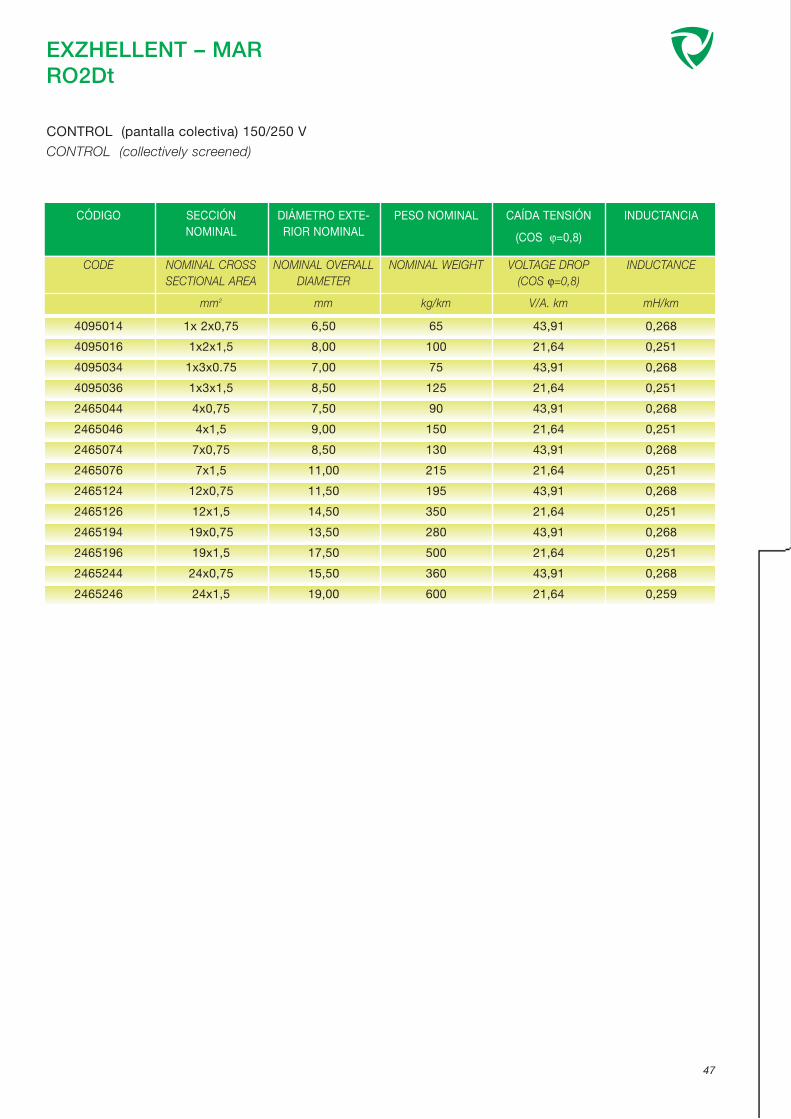
EXZHELLENT – MARRO2Dt
47
CONTROL (pantalla colectiva) 150/250 V
CONTROL (collectively screened)
CÓDIGO SECCIÓN NOMINAL
DIÁMETRO EXTE-RIOR NOMINAL
PESO NOMINAL CAÍDA TENSIÓN
(COS ϕ=0,8)
INDUCTANCIA
CODE NOMINAL CROSSSECTIONAL AREA
mm2
NOMINAL OVERALLDIAMETER
mm
NOMINAL WEIGHT
kg/km
VOLTAGE DROP (COS ϕ=0,8)
V/A. km
INDUCTANCE
mH/km
4095014
4095016
4095034
4095036
2465044
2465046
2465074
2465076
2465124
2465126
2465194
2465196
2465244
2465246
1x 2x0,75
1x2x1,5
1x3x0.75
1x3x1,5
4x0,75
4x1,5
7x0,75
7x1,5
12x0,75
12x1,5
19x0,75
19x1,5
24x0,75
24x1,5
6,50
8,00
7,00
8,50
7,50
9,00
8,50
11,00
11,50
14,50
13,50
17,50
15,50
19,00
65
100
75
125
90
150
130
215
195
350
280
500
360
600
43,91
21,64
43,91
21,64
43,91
21,64
43,91
21,64
43,91
21,64
43,91
21,64
43,91
21,64
0,268
0,251
0,268
0,251
0,268
0,251
0,268
0,251
0,268
0,251
0,268
0,251
0,268
0,259

EXZHELLENT – MARRC4Dt
IEC 60092-350 IEC 60754-1 IEC 60332-1IEC 60092-351 IEC 60754-2 IEC 60332-3-22IEC 60092-359 IEC 61034-2IEC 60092-376
1.- CONDUCTOR:
Cobre recocido clase 2.
IEC 60228.
2.- AISLAMIENTO:
Polietileno reticulado libre de halógenos (HF XLPE).
IEC 60092-351.
Identificación de conductores:ver página 29.
3.- RECUBRIMIENTO INTERNO.
4.- ARMADURA:
Trenza de alambres de cobre.
5.- CUBIERTA EXTERIOR:
Poliolefina termoplástica, librede halógenos (SHF1).
IEC 60092-359.
1.- CONDUCTOR:
Annealed copper, class 2.
IEC 60228.
2.- INSULATION:
Cross linked polyethylene (HF XLPE).
IEC 60092-351.
Cores identification: see page 29.
3.- INNER COVERING.
4.- ARMOUR:
Copper wire braid.
5.- OUTER SHEATH:
Thermoplastic polyolefine LSF (SHF1).
IEC 60092-359.
Armoured, multicore cables for installation in marine appli-cations with special performances on flame spread andlow emision of smoke and fumes.
48
CONTROL (armado, apantallado colectivo) 150/250 V
CONTROL (armoured, colectively screened)
CONSTRUCCIÓN: CONSTRUCTION:
NORMAS / STANDARDS:
MAIN USES AND FEATURES:
Cables multiconductores armados para instalación encircuitos de control en buques con especiales caracte-rísticas de no propagación del incendio y reducida emi-sión de humos opacos, gases tóxicos y corrosivos.
APLICACIONES Y CARACTERÍSTICAS PRINCIPALES:
CARACTERÍSTICAS DE DISEÑO: DESIGN CHARACTERISTICS:
Temperatura máxima del conductor en servicio perma-nente: 90°C
Tensión nominal: 150/250 V.
Max. rated conductor temperature in normal operation:90°C
Rated voltage: 150/250 V.
1
2
3
4
5

EXZHELLENT – MARRC4Dt
49
CONTROL (armado, apantallado colectivo) 150/250 V
CONTROL (armoured, colectively screened)
CÓDIGO SECCIÓN NOMINAL
DIÁMETRO BAJOARMADURANOMINAL
DIÁMETROEXTERIORNOMINAL
PESO NOMINAL CAÍDA TENSIÓN
(COS ϕ=0,8)
INDUCTANCIA
CODE NOMINAL CROSSSECTIONAL AREA
mm2
DIAMETER UNDERARMOUR NOM.
mm
NOMINAL OVE-RALL DIAMETER
mm
NOMINAL WEIGHT
kg/km
VOLTAGE DROP (COS ϕ=0,8)
V/A. km
INDUCTANCE
mH/km
2592024
2592026
2592034
2592036
2592044
2592046
2592074
2592076
2592124
2592126
2592194
2592196
2592244
2592246
2x0,75
2x1,5
3x0.75
3x1,5
4x0,75
4x1,5
7x0,75
7x1,5
12x0,75
12x1,5
19x0,75
19x1,5
24x0,75
24x1,5
5,50
6,00
5,50
6,50
6,50
7,00
8,00
9,00
11,00
12,50
13,00
15,00
15,50
17,50
9,00
9,50
9,00
10,00
10,00
10,50
11,50
12,50
14,50
16,00
17,00
19,00
19,50
22,00
115
140
130
175
150
195
200
275
310
425
415
600
520
735
43,39
21,47
43,39
21,47
43,39
21,47
43,39
21,47
43,39
21,47
43,39
21,47
43,39
21,47
0,301
0,274
0,301
0,274
0,301
0,274
0,301
0,274
0,301
0,274
0,301
0,274
0,301
0,274

EXZHELLENT – MARRO2Dt
IEC 60092-350 IEC 60754-1 IEC 60332-1IEC 60092-351 IEC 60754-2 IEC 60332-3-22IEC 60092-359 IEC 61034-2IEC 60092-376
1.- CONDUCTOR:
Cobre recocido clase 2.
IEC 60228.
2.- AISLAMIENTO:
Polietileno reticulado libre de halógenos (HF XLPE).
IEC 60092-351.
Identificación de conductores:ver página 29.
3.- RECUBRIMIENTO INTERNO.
4.- PANTALLA:
Cinta de aluminio / poliéster con conductor de drenaje.
5.- CUBIERTA EXTERIOR:
Poliolefina termoplástica, librede halógenos (SHF1).
IEC 60092-359.
1.- CONDUCTOR:
Annealed copper, stranded class 2.
IEC 60228.
2.- INSULATION:
Cross linked polyethylene (HF XLPE).
IEC 60092-351.
Core identification: see page 29.
3.- INNER COVERING.
4.- SCREEN:
Aluminium / polyester tape anddrain wire.
5.- OUTER SHEATH:
Thermoplastic polyolefin LSF (SHF1).
IEC 60092-359.
Collective screened multipair cables for installation in mari-ne applications with special performances on flame spreadand low emision of smoke and fumes.
50
INSTRUMENTACIÓN (pantalla colectiva) 150/250 V
INSTRUMENTATION (collectively screened)
CONSTRUCCIÓN: CONSTRUCTION:
NORMAS / STANDARDS:
MAIN USES AND FEATURES:
Cables multipares apantallados colectivamente parainstalación en circuitos de control en buques con espe-ciales características de no propagación del incendio yreducida emisión de humos opacos, gases tóxicos ycorrosivos.
APLICACIONES Y CARACTERÍSTICAS PRINCIPALES:
CARACTERÍSTICAS DE DISEÑO: DESIGN CHARACTERISTICS:
Temperatura máxima del conductor en servicio perma-nente: 90°C
Tensión nominal: 150/250 V.
Max. rated conductor temperature in normal operation:90°C
Rated voltage: 150/250 V.
1
2
3
4
5

EXZHELLENT – MARRO2Dt
51
INSTRUMENTACIÓN (pantalla colectiva) 150/250 V
INSTRUMENTATION (collectively screened)
CÓDIGO SECCIÓN NOMINAL
DIÁMETROEXTERIORNOMINAL
PESO NOMINAL
CODE NOMINAL CROSS SECTIO-NAL AREA
mm2
NOMINAL OVERALL DIA-METER
mm
NOMINAL WEIGHT
kg/km
4095014
4095016
4095024
4095026
4095034
4095036
4095074
4095076
4095124
4095126
4095194
4095196
4095244
4095246
4095274
4095276
1x2x0,75
1x2x1,5
2x2x0,75
2x2x1,5
3x2x0,75
3x2x1,5
7x2x0,75
7x2x1,5
12x2x0,75
12x2x1,5
19x2x0,75
19x2x1,5
24x2x0,75
24x2x1,5
27x2x0,75
27x2x1,5
6,50
8,00
9,50
11,00
10,00
12,00
13,00
16,00
17,50
21,50
21,00
25,50
24,50
30,00
25,50
30,50
65
100
105
105
130
195
230
370
385
620
555
925
710
1180
785
1285
- El cable de dos pares está cableado en cuadrete-estrella, con los conductores situados diametralmente opuestos, ej. Par 1- Azul-Negro. Par 2 Marrón-Gris.
- Constantes eléctricas y propiedades características, ver página 30
- 2 pair cables laid up in star quad configuration with the pairs identified by diametrically opposite cores, i.e. Pair 1 - Blueand Black Cores Pair 2 - Brown and Grey Cores.
- Electrical parametres and characteritic properties, see page 30

EXZHELLENT – MARR01Dt
IEC 60092-350 IEC 60754-1 IEC 60332-1IEC 60092-351 IEC 60754-2 IEC 60332-3-22IEC 60092-359 IEC 61034-2IEC 60092-376
1.- CONDUCTOR:
Cobre recocido clase 2.
IEC 60228.
2.- AISLAMIENTO:
Polietileno reticulado libre de halógenos (HF XLPE).
IEC 60092-351.
3.- PANTALLA INDIVIDUAL
de aluminio/poliéster con conductor de drenaje y encintado no metálico.
Identificación de conductores:ver página 29.
4.- RECUBRIMIENTO INTERNO.
5.- CUBIERTA EXTERIOR:
Poliolefina termoplástica, librede halógenos (SHF1).
IEC 60092-359.
1.- CONDUCTOR:
Annealed copper, strandedclass 2.
IEC 60228.
2.- INSULATION:
Cross linked polyethylene (HF XLPE).
IEC 60092-351.
3.- INDIVIDUAL SCREEN
Aluminium polyester tape withcooper drain wire and non metallic tape.
Core identification: see page 29.
4.- INNER COVERING.
5.- OUTER SHEATH:
Thermoplastic polyolefine LSF (SHF1).
IEC 60092-359.
Individually screened multipar cables for installation inmarine applications with special performances on flamespread and low emision of smoke and fumes.
52
INSTRUMENTACIÓN (pantalla individual) 150/250 V
INSTRUMENTATION (individually screened)
CONSTRUCCIÓN: CONSTRUCTION:
NORMAS / STANDARDS:
MAIN USES AND FEATURES:
Cables multipares apantallados individualmente parainstalación en circuitos de control en buques con espe-ciales características de no propagación del incendio yreducida emisión de humos opacos, gases tóxicos ycorrosivos.
APLICACIONES Y CARACTERÍSTICAS PRINCIPALES:
CARACTERÍSTICAS DE DISEÑO: DESIGN CHARACTERISTICS:
Temperatura máxima del conductor en servicio perma-nente: 90°C
Tensión nominal: 150/250 V.
Max. rated conductor temperature in normal operation:90°C
Rated voltage: 150/250 V.
1
2
3
4
5

EXZHELLENT – MARR01Dt
53
INSTRUMENTACIÓN (pantalla individual) 150/250 V
INSTRUMENTATION (individually screened)
CÓDIGO SECCIÓN NOMINAL
DIÁMETROEXTERIORNOMINAL
PESO NOMINAL
CODE NOMINAL CROSS SECTIO-NAL AREA
mm2
NOMINAL OVERALL DIA-METER
mm
NOMINAL WEIGHT
kg/km
4095014
4095016
4096024
4096026
4096034
4096036
4096074
4096076
4096124
4096126
4096194
4096196
4096244
4096246
4096274
4096276
1x 2x0,75
1x2x1,5
2x2x0.75
2x2x1,5
3x2x0,75
3x2x1,5
7x2x0,75
7x2x1,5
12x2x0,75
12x2x1,5
19x2x0,75
19x2x1,5
24x0,75
24x2x1,5
24x2x0,75
27x2x1,5
6,50
8,00
10,00
12,00
10,50
12,50
14,00
17,00
19,00
23,00
22,50
27,00
26,50
32,50
27,00
33,00
65
100
105
110
145
215
280
445
460
745
690
1105
880
1430
955
1565
Constantes eléctricas y propiedades características, ver página 30
Electrical parametres and characteritic properties, see page 30

EXZHELLENT – MARRC4Dt
IEC 60092-350 IEC 60754-1 IEC 60332-1IEC 60092-351 IEC 60754-2 IEC 60332-3-22IEC 60092-359 IEC 61034-2IEC 60092-376
1.- CONDUCTOR:
Cobre recocido clase 2.
IEC 60228.
2.- AISLAMIENTO:
Polietileno reticulado libre de halógenos (HF XLPE).
IEC 60092-351.
Identificación de conductores:ver página 29.
3.- RECUBRIMIENTO INTERNO.
4.- ARMADURA:
Trenza de alambres de cobre.
5.- CUBIERTA EXTERIOR:
Poliolefina termoplástica, librede halógenos (SHF1).
IEC 60092-359.
1.- CONDUCTOR:
Annealed copper, stranded class 2.
IEC 60228.
2.- INSULATION:
Cross linked polyethylene (HF XLPE).
IEC 60092-351.
Core identification: see page 29.
3.- INNER COVERING.
4.- ARMOUR:
Copper wire braid.
5.- OUTER SHEATH:
Thermoplastic polyolefine LSF (SHF1).
IEC 60092-359.
Armoured multipair cables for installation in marine appli-cations with special performances on flame spread andlow emision of smoke and fumes.
54
INSTRUMENTACIÓN (armado, apantallado colectivo) 150/250 V
INSTRUMENTATION (armoured, collectively screened)
CONSTRUCCIÓN: CONSTRUCTION:
NORMAS / STANDARDS:
MAIN USES AND FEATURES:
Cables multipares armados para instalación en circuitosde control en buques con especiales características deno propagación del incendio y reducida emisión dehumos opacos, gases tóxicos y corrosivos.
APLICACIONES Y CARACTERÍSTICAS PRINCIPALES:
CARACTERÍSTICAS DE DISEÑO: DESIGN CHARACTERISTICS:
Temperatura máxima del conductor en servicio perma-nente: 90°C
Tensión nominal: 150/250 V.
Max. rated conductor temperature in normal operation:90°C
Rated voltage: 150/250 V.
1
2
3
4
5

EXZHELLENT – MARRC4Dt
55
INSTRUMENTACIÓN (armado, apantallado colectivo) 150/250 V
INSTRUMENTATION (armoured, collectively screened)
CÓDIGO SECCIÓN NOMINAL
DIÁMETRO BAJOARMADURANOMINAL
DIÁMETROEXTERIORNOMINAL
PESO NOMINAL
CODE NOMINAL CROSSSECTIONAL AREA
mm2
DIAMETER UNDERARMOUR NOMINAL
mm
NOMINAL OVERALLDIAMETER
mm
NOMINAL WEIGHT
kg/km
4044014
4044016
4044024
4044026
4044034
4044036
4044044
4044046
4044073
4044074
4044075
4044076
4044124
4044126
4044194
4044196
4044244
4044246
1x2x0,75
1x2x1,5
2x2x0.75
2x2x1,5
3x2x0,75
3x2x1,5
4x2x0,75
4x2x1,5
7x2x0,5
7x2x0,75
7x2x1,00
7x2x1,5
12x2x0,75
12x2x1,5
19x2x0,75
19x2x1,50
24x2x0,75
24x2x1,5
5,50
6,00
6,50
7,00
10,00
11,50
11,50
13,50
13,00
14,00
13,50
14,00
19,50
22,00
23,50
22,50
28,50
25,00
8,00
9,00
9,50
10,50
13,50
15,50
15,00
17,50
16,50
17,50
17,50
18,50
24,00
27,00
28,00
27,50
33,00
30,50
95
120
140
170
205
280
250
345
300
360
425
520
595
850
840
1130
1045
1400
- El cable de dos pares está cableado en cuadrete-estrella, con los conductores situados diametralmente opuestos, ej. Par 1- Azul-Negro. Par 2 Marrón-Gris.
- Constantes eléctricas y propiedades características, ver página 30
- 2 pair cables laid up in star quad configuration with the pairs identified by diametrically opposite cores, i.e. Pair 1 - Blueand Black Cores Pair 2 - Brown and Grey Cores.
- Electrical parametres and characteritic properties, see page 30

EXZHELLENT – MARR01C4Dt
IEC 60092-350 IEC 60754-1 IEC 60332-1IEC 60092-351 IEC 60754-2 IEC 60332-3-22IEC 60092-359 IEC 61034-2IEC 60092-376
1.- CONDUCTOR:
Cobre recocido clase 2.
IEC 60228.
2.- AISLAMIENTO:
Polietileno reticulado libre de halógenos (HF XLPE).
IEC 60092-351.
3.- PANTALLA INDIVIDUAL
de aluminio/poliéster con conductor de drenaje y encintado no metálico.
Identificación de conductores:ver página 29.
4.- RECUBRIMIENTO INTERNO.
5.- ARMADURA:
Trenza de alambres de cobre.
6.- CUBIERTA EXTERIOR:
Poliolefina termoplástica, librede halógenos (SHF1).
IEC 60092-359.
1.- CONDUCTOR:
Annealed copper, stranded class 2.
IEC 60228.
2.- INSULATION:
Cross linked polyethylene (HF XLPE).
IEC 60092-351.
3.- INDIVIDUAL SCREEN
of aluminium/polyester tape with copper drain wire and nonmetallic tape.
Core identification: see page 29.
4.- INNER COVERING.
5.- ARMOUR:
Copper wire braid.
6.- OUTER SHEATH:
Thermoplastic polyolefine LSF (SHF1).
IEC 60092-359.
Armoured individually sreened multipair cables for installa-tion in marine applications with special performances onflame spread and low emision of smoke and fumes.
56
INSTRUMENTACIÓN (pantalla individual, armado) 150/250 V
INSTRUMENTATION (individually screened, armoured)
CONSTRUCCIÓN: CONSTRUCTION:
NORMAS / STANDARDS:
MAIN USES AND FEATURES:
Cables armados multipares apantallados individual-mente para instalación en circuitos de control enbuques con especiales características de no propaga-ción del incendio y reducida emisión de humos opacos,gases tóxicos y corrosivos.
APLICACIONES Y CARACTERÍSTICAS PRINCIPALES:
CARACTERÍSTICAS DE DISEÑO: DESIGN CHARACTERISTICS:
Temperatura máxima del conductor en servicio perma-nente: 90°C
Tensión nominal: 150/250 V.
Max. rated conductor temperature in normal operation:90°C
Rated voltage: 150/250 V.
1
2
3
4
5
6

EXZHELLENT – MARR01C4Dt
57
INSTRUMENTACIÓN (pantalla individual, armado) 150/250 V
INSTRUMENTATION (individually screened, armoured)
CÓDIGO SECCIÓN NOMINAL
DIÁMETRO BAJOARMADURANOMINAL
DIÁMETROEXTERIORNOMINAL
PESO NOMINAL
CODE NOMINAL CROSSSECTIONAL AREA
mm2
DIAMETER UNDERARMOUR NOMINAL
mm
NOMINAL OVERALLDIAMETER
mm
NOMINAL WEIGHT
kg/km
4044014
4044016
4045024
4045026
4045034
4045036
4045044
4045046
4045074
4045076
4045124
4045126
4045194
4045196
4045244
4045246
1x2x0,75
1x2x1,5
2x2x0.75
2x2x1,5
3x2x0,75
3x2x1,5
4x2x0,75
4x2x1,50
7x2x0,75
7x2x1,50
12x2x0,75
12x2x1,50
19x2x0,75
19x2x1,50
24x2x0,75
24x2x1,5
5,50
6,00
10,00
11,00
10,50
12,00
12,00
13,50
15,00
16,50
20,00
23,00
24,50
27,50
29,00
33,00
8,00
9,00
13,00
14,50
14,00
15,50
15,50
17,00
18,50
21,00
24,50
27,50
29,00
32,50
34,00
38,50
95
120
230
260
230
335
280
385
415
600
675
930
975
1375
1215
1715
Constantes eléctricas y propiedades características, ver página 30
Electrical parametres and characteritic properties, see page 30

EXZHELLENT – MARRDt-M
IEC 60092-350 IEC 60754-1 IEC 60331-21IEC 60092-351 IEC 60754-2 IEC 60332-1IEC 60092-353 IEC 61034-2 IEC 60332-3-22IEC 60092-359
1.- CONDUCTOR:
Cobre recocido clase 2.
IEC 60228.
2.- ENCINTADO DE MICA.
3.- AISLAMIENTO:
Polietileno reticulado libre de halógenos (HF XLPE).
IEC 60092-351.
Identificación de conductores:ver página 28.
4.- RECUBRIMIENTO INTERNO:
Poliolefina termoplástica, librede halógenos (Opcional).
5.- CUBIERTA EXTERIOR:
Poliolefina termoplástica, librede halógenos (SHF1).
IEC 60092-359.
1.- CONDUCTOR:
Annealed copper, stranded class 2.
IEC 60228.
2.- MICA TAPE.
3.- INSULATION:
Cross linked polyethylene (HF XLPE).
IEC 60092-351.
Core identification: see page 28.
4.- INNER COVERING:
Thermoplastic polyolefine LSF. (Opcional).
5.- OUTER SHEATH:
Thermoplastic polyolefin LSF (SHF1).
IEC 60092-359.
Cables for installation in marine applications with specialperformances on flame spread, fire resistance and lowemision of smoke and fumes.
58
ENERGÍA 0,6/1 kV
POWER
CONSTRUCCIÓN: CONSTRUCTION:
NORMAS / STANDARDS:
MAIN USES AND FEATURES:
Cables para instalación en buques con especialescaracterísticas de no propagación del incendio, resis-tente al incendio y reducida emisión de humos opacos,gases tóxicos y corrosivos.
APLICACIONES Y CARACTERÍSTICAS PRINCIPALES:
CARACTERÍSTICAS DE DISEÑO: DESIGN CHARACTERISTICS:
Temperatura máxima del conductor en servicio perma-nente: 90°C
Tensión nominal: 0,6/1 (1,2) kV.
Max. rated conductor temperature in normal operation:90°C
Rated voltage: 0,6/1 (1,2) kV.
1
2
3
4
5

EXZHELLENT – MARRDt-M
59
ENERGÍA 0,6/1 kV
POWER
CÓDIGO SECCIÓN NOMINAL
DIÁMETROEXTERIORNOMINAL
PESO NOMINAL INTENSIDADADMISIBLE AIRE
45°C
CAÍDA TENSIÓN
(COS ϕ=0,8)
INDUCTANCIA
CODE NOMINAL CROSSSECTIONAL AREA
mm2
NOMINAL OVE-RALL DIAMETER
mm
NOMINAL WEIGHT
kg/km
CURRENT RATINGAIR 45° C
A
VOLTAGE DROP (COS ϕ=0,8)
V/A. km
INDUCTANCE
mH/km
7595206
7595207
7595208
7595306
7595307
7595308
7595309
7595310
7595311
7595312
7595313
7595314
7595315
7595316
7595317
7595318
7595406
7595407
7595408
7595409
7595410
7595411
7595412
7595413
7595414
2629056
2629057
2629076
2629077
2629126
2629127
2629196
2629197
2629276
2629277
2x1,5
2x2,5
2x4
3x1,5
3x2,5
3x4
3x6
3x10
3x16
3x25
3x35
3x50
3x70
3x95
3x120
3x150
4x1,5
4x2,5
4x4
4x6
4x10
4x16
4x25
4x35
4x50
5x1,5
5x2,5
7x1,5
7x2.5
12x1,5
12x2,5
19x1,5
19x2,5
27x1,5
27x2,5
8,60
9,60
10,50
9,30
10,50
11,50
13,00
14,50
17,00
20,50
23,00
29,00
33,00
37,00
41,50
46,00
10,00
11,00
12,50
14,00
16,50
19,00
23,00
25,50
29,50
11,5
12,5
12,5
14
16,5
18,5
20
22
24
26,5
105
140
185
125
165
225
300
440
640
975
1310
2010
2745
3635
4565
5590
150
200
280
365
560
815
1250
1680
2265
185
250
230
315
380
515
555
765
765
1070
23
31
43
20
28
37
47
65
87
110
137
167
214
259
301
347
13
18
24
31
43
57
75
93
116
12
17
11
15
9
12
8
11
7
9
21,50
13,20
8,25
21,50
13,20
8,25
5,54
3,33
2,12
1,37
1,01
0,77
0,55
0,42
0,35
0,30
21,50
13,20
8,25
5,54
3,33
2,12
1,37
1,01
0,77
21,477
13,18
21,477
13,183
21,477
13,183
21,477
13,183
21,477
13,183
0,367
0,341
0,320
0,367
0,341
0,320
0,301
0,283
0,270
0,269
0,260
0,252
0,243
0,237
0,234
0,233
0,367
0,341
0,320
0,301
0,283
0,270
0,269
0,260
0,252
0,3025
0,277
0,3025
0,2773
0,3025
0,2773
0,3025
0,2773
0,3025
0,2773

EXZHELLENT – MARRDtC4Dt-M
IEC 60092-350 IEC 60754-1 IEC 60331-21IEC 60092-351 IEC 60754-2 IEC 60332-1IEC 60092-353 IEC 61034-2 IEC 60332-3-22IEC 60092-359
1.- CONDUCTOR:
Cobre recocido clase 2.
IEC 60228.
2,- ENCINTADO DE MICA
3.- AISLAMIENTO:
Polietileno reticulado libre de halógenos (HF XLPE).
IEC 60092-351.
Identificación de conductores:ver página 28.
4.- RECUBRIMIENTO INTERNO:
Poliolefina termoplástica, librede halógenos.
5.- ARMADURA:
Trenza de alambres de cobre.
6.- CUBIERTA EXTERIOR:
Poliolefina termoplástica, librede halógenos (SHF1).
IEC 60092-359.
1.- CONDUCTOR:
Annealed copper, stranded class 2.
IEC 60228.
2.- MICA TAPE.
3.- INSULATION:
Cross linked polyethylene (HF XLPE).
IEC 60092-351.
Core identification: see page 28.
4.- INNER COVERING:
Thermoplastic polyolefine LSF.
5.- ARMOUR:
Copper wire braid.
6.- OUTER SHEATH:
Thermoplastic polyolefin LSF (SHF1).
IEC 60092-359.
Armoured cables for installation in marine applications withspecial performances on flame spread, fire resistance andlow emision of smoke and fumes.
60
ENERGÍA 0,6/1 kV
POWER
CONSTRUCCIÓN: CONSTRUCTION:
NORMAS / STANDARDS:
MAIN USES AND FEATURES:
Cables armados para instalación en buques con espe-ciales características de no propagación del incendio,resistente al incendio y reducida emisión de humosopacos, gases tóxicos y corrosivos.
APLICACIONES Y CARACTERÍSTICAS PRINCIPALES:
CARACTERÍSTICAS DE DISEÑO: DESIGN CHARACTERISTICS:
Temperatura máxima del conductor en servicio perma-nente: 90°C
Tensión nominal: 0,6/1 (1,2) kV.
Max. rated conductor temperature in normal operation:90°C
Rated voltage: 0,6/1 (1,2) kV.
1
2
3
4
5
6

EXZHELLENT – MARRDtC4Dt-M
61
ENERGÍA 0,6/1 kV
POWER
CÓDIGO SECCIÓN NOMINAL
DIÁMETRO BAJOARMADURANOMINAL
DIÁMETROEXTERIORNOMINAL
PESO NOMINAL INTENSIDADADMISIBLE AIRE
45°C
CAÍDA TENSIÓN
(COS ϕ=0,8)
INDUCTANCIA
CODE NOMINAL CROSSSECTIONAL AREA
mm2
DIAMETER UNDERARMOUR NOM.
mm
NOMINAL OVE-RALL DIAMETER
mm
NOMINAL WEIGHT
kg/km
CURRENT RATINGAIR 45° C
A
VOLTAGE DROP (COS ϕ=0,8)
V/A. km
INDUCTANCE
mH/km
7597206
7597207
7597208
7597306
7597307
7597308
7597309
7597310
7597311
7597312
7597313
7597314
7597315
7597316
7597317
7597318
7597406
7597407
7597408
7597409
7597410
7597411
7597412
7597413
7597414
2x1,5
2x2,5
2x4
3x1,5
3x2,5
3x4
3x6
3x10
3x16
3x25
3x35
3x50
3x70
3x95
3x120
3x150
4x1,5
4x2,5
4x4
4x6
4x10
4x16
4x25
4x35
4x50
8,50
9,50
10,50
9,00
10,00
11,00
12,50
14,50
16,00
19,50
22,00
25,00
29,00
33,00
37,00
41,50
10,00
11,00
12,00
13,50
15,50
18,00
21,50
24,50
28,00
11,50
12,50
13,50
12,50
13,50
14,50
16,50
18,50
20,50
24,00
26,50
30,00
34,50
39,00
43,50
48,00
13,50
14,50
16,00
17,50
20,00
22,50
26,50
29,50
33,00
205
250
300
235
280
350
480
660
865
1255
1620
2105
2895
3875
4820
5855
265
325
450
555
780
1065
1555
2025
2640
23
31
43
20
28
37
47
65
87
110
137
167
214
259
301
347
13
18
24
31
43
57
75
93
116
21,50
13,20
8,25
21,50
13,20
8,25
5,54
3,33
2,12
1,37
1,01
0,77
0,55
0,42
0,35
0,30
21,50
13,20
8,25
5,54
3,33
2,12
1,37
1,01
0,77
0,367
0,341
0,320
0,367
0,341
0,320
0,301
0,283
0,270
0,269
0,260
0,252
0,243
0,237
0,234
0,233
0,367
0,341
0,320
0,301
0,283
0,270
0,269
0,260
0,252

EXZHELLENT – MARRC4Dt-M
IEC 60092-350 IEC 60754-1 IEC 60331-21IEC 60092-351 IEC 60754-2 IEC 60332-1IEC 60092-359 IEC 61034-2 IEC 60332-3-22IEC 60092-376
1.- CONDUCTOR:
Cobre recocido clase 2.
IEC 60228.
2.- ENCINTADO DE MICA.
3.- AISLAMIENTO:
Polietileno reticulado libre de halógenos (HF XLPE).
IEC 60092-351.
Identificación de conductores:ver página 29.
4.- RECUBRIMIENTO INTERNO.
5.- PANTALLA:
Trenza de alambres de cobre.
6.- CUBIERTA EXTERIOR:
Poliolefina termoplástica, librede halógenos (SHF1).
IEC 60092-359.
1.- CONDUCTOR:
Annealed copper, stranded class 2.
IEC 60228.
2.- MICA TAPE.
3.- INSULATION:
Cross linked polyethylene (HF XLPE).
IEC 60092-351.
Core identification: see page 29.
4.- INNER COVERING.
5.- SCREEN:
Copper wire braid.
6.- OUTER SHEATH:
Thermoplastic polyolefinE LSF (SHF1).
IEC 60092-359.
Sreened multicore cables for installation in marine applica-tions with special performances on flame spread, fire resis-tance and low emision of smoke and fumes.
62
CONTROL (armado) 150/250 V
CONTROL (armoured)
CONSTRUCCIÓN: CONSTRUCTION:
NORMAS / STANDARDS:
MAIN USES AND FEATURES:
Cables multiconductores apantallados para instalaciónen circuitos de control en buques con especiales carac-terísticas de no propagación del incendio, resistente alincendio y reducida emisión de humos opacos, gasestóxicos y corrosivos.
APLICACIONES Y CARACTERÍSTICAS PRINCIPALES:
CARACTERÍSTICAS DE DISEÑO: DESIGN CHARACTERISTICS:
Temperatura máxima del conductor en servicio perma-nente: 90°C
Tensión nominal: 150/250 V.
Max. rated conductor temperature in normal operation:90°C
Rated voltage: 150/250 V.
1
2
3
4
5
6

EXZHELLENT – MARRC4Dt-M
63
CONTROL (armado) 150/250 V
CONTROL (armoured)
CÓDIGO SECCIÓN NOMINAL
DIÁMETRO BAJOARMADURA NOMI-
NAL
DIÁMETROEXTERIORNOMINAL
PESO NOMINAL CAÍDA TENSIÓN
(COS ϕ=0,8)
INDUCTANCIA
CODE NOMINAL CROSSSECTIONAL AREA
mm2
DIAMETER UNDERARMOUR NOMINAL
mm
NOMINAL OVERALLDIAMETER
mm
NOMINAL WEIGHT
kg/km
VOLTAGE DROP (COS ϕ=0,8)
V/A. km
INDUCTANCE
mH/km
2596024
2596026
2596034
2596036
2596044
2596046
2596074
2596076
2596124
2596126
2596194
2596196
2596244
2596246
2x0,75
2x1,5
3x0,75
3x1,5
4x0,75
4x1,5
7x0,75
7x1,5
12x0,75
12x1,5
19x0,75
19x1,5
24x0,75
24x1,5
6,50
6,50
6,50
7,00
7,00
8,00
9,00
10,00
12,50
13,50
14,50
16,50
17,50
19,50
9,50
10,00
10,00
11,00
10,50
11,50
12,50
13,50
16,00
17,50
19,00
20,50
22,00
24,00
130
160
145
180
165
220
230
305
350
460
480
650
590
800
43,39
21,48
43,39
21,48
43,39
21,48
43,39
21,48
43,39
21,48
43,39
21,48
43,39
21,48
0,325
0,296
0,325
0,296
0,325
0,296
0,325
0,296
0,325
0,296
0,325
9,296
0,325
0,296

EXZHELLENT – MARRC4Dt-M
IEC 60092-350 IEC 60754-1 IEC 60331-21IEC 60092-351 IEC 60754-2 IEC 60332-1IEC 60092-359 IEC 61034-2 IEC 60332-3-22IEC 60092-376
1.- CONDUCTOR:
Cobre recocido clase 2.
IEC 60228.
2.- ENCINTADO DE MICA.
3.- AISLAMIENTO:
Polietileno reticulado libre de halógenos (HF XLPE).
IEC 60092-351.
Identificación de conductores:ver página 29.
4.- RECUBRIMIENTO INTERNO.
5.- PANTALLA:
Trenza de alambres de cobre.
6.- CUBIERTA EXTERIOR:
Poliolefina termoplástica, librede halógenos (SHF1).
IEC 60092-359.
1.- CONDUCTOR:
Annealed copper, stranded class 2.
IEC 60228.
2.- MICA TAPE.
3.- INSULATION:
Cross linked polyethylene (HF XLPE).
IEC 60092-351.
Core identification: see page 29.
4.- INNER COVERING.
5.- SCREEN:
Copper wire braid.
6.- OUTER SHEATH:
Thermoplastic polyolefine LSF (SHF1).
IEC 60092-359.
Collectively sreened multipair cables for installation in mari-ne applications with special performances on flame spre-ad, fire resistance and low emision of smoke and fumes.
64
INSTRUMENTACIÓN (armado, apantallado colectivo) 150/250 V
INSTRUMENTATION (armoured, collectively screened)
CONSTRUCCIÓN: CONSTRUCTION:
NORMAS / STANDARDS:
MAIN USES AND FEATURES:
Cables multipares apantallados colectivamente parainstalación en circuitos de control en buques con espe-ciales características de no propagación del incendio,resistencia al incendio y reducida emisión de humosopacos, gases tóxicos y corrosivos.
APLICACIONES Y CARACTERÍSTICAS PRINCIPALES:
CARACTERÍSTICAS DE DISEÑO: DESIGN CHARACTERISTICS:
Temperatura máxima del conductor en servicio perma-nente: 90°C
Tensión nominal: 150/250 V.
Max. rated conductor temperature in normal operation:90°C
Rated voltage: 150/250 V.
12
3
45
6

EXZHELLENT – MARRC4Dt-M
65
INSTRUMENTACIÓN (armado, apantallado colectivo) 150/250 V
INSTRUMENTATION (armoured, collectively screened)
CÓDIGO SECCIÓN NOMINAL
DIÁMETRO BAJOARMADURANOMINAL
DIÁMETROEXTERIORNOMINAL
PESO NOMINAL
CODE NOMINAL CROSSSECTIONAL AREA
mm2
DIAMETER UNDERARMOUR NOMINAL
mm
NOMINAL OVERALLDIAMETER
mm
NOMINAL WEIGHT
kg/km
4046014
4046016
4046024
4046026
4046034
4046036
4046044
4046046
4046074
4046076
4046124
4046126
4046194
4046196
4046244
4046246
1x2x0,75
1x2x1,5
2x2x0.75
2x2x1,5
3x2x0,75
3x2x1,5
4x2x0,75
4x2x1,50
7x2x0,75
7x2x1,50
12x2x0,75
12x2x1,50
19x2x0,75
19x2x1,50
24x2x0,75
24x2x1,5
6,00
6,50
7,00
8,00
11,50
13,00
13,00
14,50
17,00
18,00
22,00
24,50
22,50
30,00
32,00
35,50
9,00
10,00
10,50
11,00
15,00
17,00
16,00
18,50
20,50
22,50
26,50
29,50
27,00
35,00
36,50
41,00
105
130
150
185
230
340
275
400
410
605
680
955
870
1385
1165
1715
- El cable de dos pares está cableado en cuadrete-estrella, con los conductores situados diametralmente opuestos, ej. Par 1- Azul-Negro. Par 2 Marrón-Gris.
- Constantes eléctricas y propiedades características, ver página 30
- 2 pair cables laid up in star quad configuration with the pairs identified by diametrically opposite cores, i.e. Pair 1 - Blueand Black Cores Pair 2 - Brown and Grey Cores.
- Electrical parametres and characteritic properties, see page 30


CA
BL
ES
PA
RA
PL
ATA
FO
RM
AS
/ O
FF
SH
OR
E C
AB
LES


69
INFORMACIÓN TÉCNICA TECHNICAL INFORMATION
DESIGNACIÓN DEL CABLE
La referencia de los cables está basada en el código deletras de las tablas siguientes:
CABLE DESIGNATION
Cable designation is based in the letter code described inthe tables below:
Diseño libre de halógenos / Halogen free designMateriales Aislamiento Recubrimiento o encintado Armadura/Pantalla Cubierta Materials Insulation Bedding/inner Sheath Armour/Shield Outer Sheath
Aislamiento más cinta resistente al incendio.Fire resistant tape + insulation
B
Caucho Etileno Propileno (EPR)Ethylene Propylene Rubber (EPR)
R
Polietileno reticulado XLPECross-linked Polyethylene XLPE
T
Compuesto termoplásticoThermoplastic compound
I
Compuesto termoestableThermoset compound EMA or EVA
U
Recubrimiento o encintadoBedding or taping
F
Pantalla (soporte PE o PP)Screen (poss. with PE or PP)
Y
Aluminio (laminado)Aluminium (laminated)
L
Sin armaduraNo armour
X
Trenza alambres cobreCopper wire braid
O
Compuesto termoplástico SHF1Thermoplastic compound SHF1
I
Compuesto termoestable
SHF2 o SHF MudThermoset compound U
SHF2 or SHF Mud
Compuesto resistente aHidrocarburos SE1SE1 Hydrocarbon resistant
B

70
TOLERANCIAS DIÁMETRO EXTERIOR / CABLE OVERALL DIAMETER TOLERANCEDiámetro exterior Tolerancia mm / Tolerance mm
nominal mmNominal overall Baja tensión Instrumentación y control Media tensióndiameter mm Low voltage Instrumentation & control Medium voltage
< 20 -0.50 + 1.0 -1 2.0 -1.0 +2.0
20 – 29.9 -0.50 +2.0 -1 2.5 -1.0 +2.5
30 – 39.9 -0.75 +2.5 -1,5 3.0 -1.5 +3.0
40 – 49.9 -0.75 +3.0 -1,5 4.0 -1.5 +4.0
50 – 59.9 -0.75 +3.5 -1.5 4.5 -1.5 +4.5
60 – 69.9 - 1.0 +4.0 -1.5 5.0 -1.5 +5.0
70 – 79.9 - 1.0 +5.0 -1.5 6.0 -1.5 +6.0
> 79.9 - 1.0 +5.5 -1.5 6.5 -1.5 +6.5
En las denominaciones de los cables se incluye el núme-ro y sección de los conductores (NxS). Se añade el sufi-jo "+E" cuando se requiere un conductor para puesta atierra, (NxS+E). En los cables de dos o tres conductores,se usa la terminología (NxS/E) para mostrar los cables enlos cuales, se puede utilizar la trenza de cobre comoconductor de tierra. En este caso, la sección de la tren-za es igual o superior al 50% de los conductores de fase.
The cable designation also includes the number and size ofcores (NxS), when an earth core is required, the suffix "+E"is used, (NxS+E). In 2 and 3 core cables, the NxS/E termi-nology is used to illustrate the cables in wich the copperwire braid armour can be employed as the earth conduc-tor. In this case, the cross sectional area of the braid isequal or greater than 50% of the phase conductors.
INTENSIDADES ADMISIBLESLas intensidades admisibles que aparecen en este catá-logo, están de acuerdo con la tabla 5 de la norma IEC61892-4 basada en una temperatura de trabajo del con-ductor de 90º C y temperatura ambiente de 45º C. Losvalores especificados están basados en las condicionesde instalación siguientes,
- Cables multiconductores instalados al aire, método de instalación E.
- Conductores unipolares en contacto al aire, formación trébol método de instalación F.
En la norma IEC 61892-4, se especifican los factores aaplicar para temperaturas distintas a las citadas, otrostipos de instalación o agrupamientos de cables.
CURRENT CARRYING CAPACITIESThe current ratings stated in this catalogue are in com-pliance with IEC 61892-4 Table 5, based upon a maximumconductor operating temperature of 90º C, and an ambienttemperature of 45º C. The specified ratings are basedupon the following installation conditions,
- Multicore cables in free air installation, method E.
- Single core cables touching, in trefoil configuration,installation method F.
De-rating factors for differing methods of installation, andambient temperatures are specified in IEC 61892-4.

71
Superior a 1,8/3 kV - Higher than 1,8/3 kVPosición final/Final position
Unipolares
Single core
Tripolares
3 core cable
Cualquiera
Any
Cualquiera
Any
Cualquiera
Any
Cualquiera
Any
10 D
8 D
Durante el tendido / During laying up
Unipolares
Single core
Tripolares
3 core cable
Cualquiera
Any
Cualquiera
Any
Cualquiera
Any
Cualquiera
Any
20 D
16 D
RADIOS DE CURVATURA MÍNIMOS / MINIMUM BENDING RADIUS (IEC 60092-352)
Hasta 1,8/3 kV inclusive – Up to and including 1,8/3 kV
Aislamiento
Insulation
Termoplástico o termoestable
Conductores circularesde cobre.
Thermoplastic orThermosetting.
Circular copperconductors
Protección
Covering
Sin armadura ni trenza
Unarmoured or unbraided
Con armadura o pantalla detrenza metálica
Metal braid screened orarmoured
Cinta compositepoliéster/metal
apantallamiento unidades o colectivo
Composite polyester/metaltape screened units or
collective tape screening
Diámetro exteriornominal
Nominal overall diameter(D)
< 25 mm
> 25 mm
Cualquiera
Any
Cualquiera
Any
Radio Interior Curvaturamínimo
Minimum internal Radius of bend
4 D
6 D
6 D
8 D

72
IDENTIFICACIÓN CONDUCTORES (CABLES PARA PLATAFORMAS) / CORE IDENTI-FICATION (OFFSHORE CABLES):
Cables energía hasta 1,8/3 kV inclusive/ Power cables up to and including 1,8/3 kVNº conductores Protección Fases
Number of cores Earth Phase
2 - Natural Negro
Off white Black - -
2+E Amarillo-Verde Natural Negro
Green-yellow Off white Black - -
3 - Natural Negro Rojo
Off white Black Red -
3+E Amarillo-Verde Natural Negro Rojo
Green-yellow Off white Black Red -
4 - Natural Negro Rojo Azul
Off white Black Red Blue
“n” Aislamiento blanco, conductores numerados
White insulation, printed numbered cores
Cubierta negra / Black sheath
Cables energía MT superior a 1,8/3 kV / MV power cables, higher than 1,8/3 kVNº conductoresNumber of cores
3 Gris Negro RojoGrey Black Red
Cubierta roja / Red sheath

73
Cables control 250 V / Control cables 250 VNº conductoresNumber of cores
“n” Aislamiento negro, conductores numeradosBlack insulation, printed numbered cores
Cubierta gris / Grey sheath
Circuitos intrínsecamente seguros: Cubierta de color azul / Intrinsically safe circuits: Blue sheath
Cables instrumentation 250 V / Instrumentation cables 250 VConductores / Cores
Par (*) Azul NegroPair (*) Blue Black -
Trio Azul Negro MarrónTriple Blue Black Brown
Cada par o trío numerado (cinta) / Each pair or triple numbered (tape)
Cubierta gris / Grey sheath
Circuitos intrínsecamente seguros: Cubierta de color azul / Intrinsically safe circuits: Blue sheath
(*) El cable de dos pares con pantalla colectiva está cableado en cuadrete-estrella, con los conductores situados dia-metralmente opuestos: Par 1- Azul-Negro. Par 2 Marrón-Gris. / Two pairs cables collectively screened are laid up in starquad configuration with the pairs identified by diametrically opposite cores: Pair 1 - Blue and Black Cores Pair 2 - Brownand Grey Cores.

74
Sección conductoresConductor cross sectional area
mm2
RFOU / RFOU/B BFOU / BFOU/B
1,0 1,5 1,0 1,5
PropiedadesEléctricas
ElectricalProperties
PropiedadesCaracterísticas
CharacteristicProperties
Resistencia cond.(DC) 20 °C
Cond. Resistance(DC) 20°C
Resistencia cond.(AC) 20 °C
Cond. Resistance(AC) 20°C
Capacidad mutuamax.
Mutual capacitancemin.
Inductancia
Inductance
Impedancia
Impedance
Impedanciacaracterística
Characteristicimpedance
Atenuación señal
Signal attenuation
15
30
76
0,55
2100
253
0,70
13
25
80
0,53
2000
225
0,64
15
30
71
0,59
2250
262
0,67
13
25
74
0,57
2150
233
0,62
Ω/km
Ω/km
nF/km
mH/km
Ω
Ω
dB/km
DATOS TÉCNICOS CABLES INSTRUMENTACIÓN PARA PLATAFORMAS
TECHNICAL DATA FOR OFFSHORE INSTRUMENTATION CABLES
Unidades
Units
Valores @ 1000 Hz
Data @ 1000 Hz

75
2
3
4
56789
2
3
4
56789
100000100001000100
0.1
10.0
1.0
Frecuencia (Hz) / Frequency (Hz)
Ate
nuac
ión
(dB
/km
) /
Att
enu
atio
n (
dB
/km
)

CABLES PARA PLATAFORMASCABLES FOR OFFSHORE INSTALLATIONS
76
TENSIÓNRATED VOLTAGE
0,6/1 kV
3,6/6 kV
6/10 kV
8,7/15 kV
12/20 kV
3,6/6 kV
6/10 kV
8,7/15 kV
12/20 kV
250 V
TIPOTYPE
Type P1 RFOU
Type P1 TFOU
Type P1/P8 RFOU
Type P1/P8 TFOU
Type P18 RU
Type P2 RFOU
Type P3 RFOU
Type P4 RFOU
Type P19 RFOU
Type P2/P9 RFOU
Type P3/P10 RFOU
Type P4/P11 RFOU
Type P19/P21 RFOU
Type S1 RFOU(i)
Type S2 RFOU(c)
Type S11 RU(i)
Type S12 RU(c)
Type S1/S5 RFOU(i)
Type S2/S6 RFOU(c)
ARMADURAARMOURED
x
x
x
x
-
x
x
x
x
x
x
x
x
x
x
-
-
x
x
SERIESERIE
74752469
74712471
74762470
74722472
7479
7480
7481
7482
7483
7484
7485
7486
7487
42714281
42724282
4267
4268
42734283
42744284
PÁGINAPAGE
78
80
82
84
86
89
89
89
89
91
91
91
91
92
94
96
98
100
102
GUÍA DE SELECCIÓN / CABLE SELECTION
RES. FANGOSMUD RESISTANT
-
-
x
x
-
-
-
-
-
x
x
x
x
x
x
-
-
x
x
ENERGIAB.T.
POWER L.V.
ENERGIA M.T.
POWER M.V.
INSTRUMENTACION
INSTRUMENTATION

77
CABLES PARA CIRCUITOS DE SEGURIDAD (IEC 60331) RESISTENTES AL FUEGOCIRCUIT INTEGRITY CABLES (IEC 60331) FIRE RESISTANT
TENSIÓNRATED VOLTAGE
0,6/1 kV
250 V
TIPOTYPE
Type P5 BFOU
Type P5/P12 BFOU
Type P17 BU
Type S3 BFOU(i)
Type S4 BFOU(c)
Type S13 BU (i)
Type S14 BU (c)
Type S3/S7 BFOU(i)
Type S4/S8 BFOU(c)
ARMADURAARMOURED
x
x
-
x
x
-
-
x
x
SERIESERIE
74732473
74742474
7478
42754285
42764286
4269
4270
42774287
42784288
PÁGINAPAGE
104
106
108
110
112
114
116
118
120
RES. FANGOSMUD RESISTANT
-
x
-
-
-
-
-
x
x
ENERGIAB.T.
POWER L.V.
INSTRUMENTACION
INSTRUMENTATION
CABLES PARA ALIMENTACIÓN DE SISTEMAS CON VARIACIÓN DE FRECUENCIACABLES FOR VARIABLE FREQUENCY DRIVE
TENSIÓNRATED VOLTAGE
0,6/1 kV
TIPOTYPE
Type RFOU-VFD
ARMADURAARMOURED
x
SERIESERIE
7490
PÁGINAPAGE
122
RES. FANGOSMUD RESISTANT
xENERGIA B.T.
POWER L.V.
GU
ÍA D
E S
ELE
CC
IÓN
/ C
AB
LE S
ELE
CT
ION

EXZHELLENT – MARType P1 RFOU
IEC 60092-351 IEC 60754-1 IEC 60332-1IEC 60092-353 IEC 60754-2 IEC 60332-3-22IEC 60092-359 IEC 61034NEK 606:2004
1.- CONDUCTOR:
Cobre estañado recocido clase 2.
IEC 60228.
2.- AISLAMIENTO:
Etileno Propileno LSF (EPR).
IEC 60092-351.
Identificación de conductores:ver página 72.
3.- ASIENTO:
Compuesto libre de halógenos.
4.- ARMADURA:
Trenza de alambres de cobre estañado.
5.- CUBIERTA EXTERIOR:
Compuesto termoestable tipoSHF2.
IEC 60092-359.
1.- CONDUCTOR:
Tinned copper, stranded class 2.
IEC 60228.
2.- INSULATION:
Ethylene Propylene Rubber LSF(EPR).
IEC 60092-351.
Core identification: see page 72.
3.- BEDDING:
Halogen free compound.
4.- BRAID ARMOUR:
Tinned copper wire braid.
5.- OUTER SHEATH:
Thermoset compound type SHF2.
IEC 60092-359.
Armoured cables for installation in offshore applicationswith special performances on flame spread and low emis-sion of smoke and fumes.
Oil resistant.
78
ENERGÍA 0,6/1 kV
POWER
CONSTRUCCIÓN: CONSTRUCTION:
NORMAS / STANDARDS:
MAIN USES AND FEATURES:
Cables armados para instalación en plataformas conespeciales características de no propagación del incen-dio y reducida emisión de humos opacos, gases tóxicosy corrosivos.
Resistente a los aceites.
APLICACIONES Y CARACTERÍSTICAS PRINCIPALES:
CARACTERÍSTICAS DE DISEÑO: DESIGN CHARACTERISTICS:
Temperatura máxima del conductor en servicio perma-nente 90°C
Tensión nominal: 0,6/1 (1,2) kV.
Max. rated conductor temperature in normal operation:90°C.
Rated voltage: 0,6/1 (1,2) kV.
1
2
3
4
5

EXZHELLENT – MARType P1 RFOU
79
ENERGÍA 0,6/1 kV
POWER
CÓDIGO SECCIÓN NOMINAL
DIÁMETRO BAJOARMADURANOMINAL
DIÁMETROEXTERIORNOMINAL
PESO NOMINAL INTENSIDADADMISIBLE AIRE
45°C
CAÍDA TENSIÓN
(COS ϕ=0,8)
INDUCTANCIA
CODE NOMINAL CROSSSECTIONAL AREA
mm2
DIAMETER UNDERARMOUR NOM.
mm
NOMINAL OVE-RALL DIAMETER
mm
NOMINAL WEIGHT
kg/km
CURRENT RATINGAIR 45° C
A
VOLTAGE DROP (COS ϕ=0,8)
V/A. km
INDUCTANCE
mH/km
7475206
7475207
7475208
7475306
7475307
7475308
7475309
7475310
7475311
7475312
7475313
7475314
7475315
7475316
7475317
7475318
7475406
7475407
2x1,5
2x2,5
2x4
3x1,5
3x2,5
3x4
3x6
3x10
3x16
3x25
3x35
3x50
3x70
3x95
3x120
3x150
4x1,5
4x2,5
9,00
10,00
11,00
9,50
10,50
11,50
13,50
15,50
17,50
20,50
23,00
26,50
30,00
34,50
41,00
45,50
10,50
11,50
12,50
13,50
15,00
13,00
14,50
15,50
17,50
19,50
22,00
25,50
28,00
32,00
36,50
41,00
47,50
52,50
14,50
15,50
240
290
385
275
365
440
560
745
1015
1405
1790
2435
3290
4470
5975
7320
350
430
23
31
43
20
28
37
47
65
87
110
137
167
214
259
301
347
20
28
21,68
13,47
8,41
21,68
13,47
8,41
5,60
3,35
2,14
1,39
1,02
0,78
0,56
0,43
0,35
0,30
21,68
13,47
0,376
0,350
0,328
0,376
0,350
0,328
0,317
0,296
0,281
0,278
0,268
0,264
0,250
0,248
0,231
0,231
0,376
0,350
2469056
2469057
2469076
2469077
2469126
2469127
2469196
2469197
5x1,5
5x2,5
7x1,5
7x2,5
12x1,5
12x2,5
19x1,5
19x2,5
11,50
13,00
12,50
14,00
17,00
18,50
20,00
22,00
16,00
17,00
17,00
18,00
21,50
23,00
24,50
27,00
420
515
485
595
730
915
990
1260
-
-
-
-
-
-
-
-
21,68
13,47
21,68
13,47
21,68
13,47
21,68
13,47
0,376
0,350
0,376
0,350
0,376
0,350
0,376
0,350

EXZHELLENT – MARType P1 TFOU
IEC 60092-351 IEC 60754-1 IEC 60332-1IEC 60092-353 IEC 60754-2 IEC 60332-3-22IEC 60092-359 IEC 61034NEK 606:2004
1.- CONDUCTOR:
Cobre estañado recocido clase 2.
IEC 60228.
2.- AISLAMIENTO:
Polietileno reticulado LSF (HF XLPE).
IEC 60092-351.
Identificación de conductores:ver página 72.
3.- ASIENTO:
Compuesto libre de halógenos.
4.- ARMADURA:
Trenza de alambres de cobre estañado.
5.- CUBIERTA EXTERIOR:
Compuesto termoestable tipoSHF2.
IEC 60092-359.
1.- CONDUCTOR:
Tinned copper, stranded class 2.
IEC 60228.
2.- INSULATION:
Cross-linked polyethylene LSF (HF XLPE).
IEC 60092-351.
Core identification: see page 72.
3.- BEDDING:
Halogen free compound.
4.- BRAID ARMOUR:
Tinned copper wire braid.
5.- OUTER SHEATH:
Thermoset compound type SHF2.
IEC 60092-359.
Armoured cables for installation in offshore applicationswith special performances on flame spread and low emis-sion of smoke and fumes.
Oil resistant.
80
ENERGÍA 0,6/1 kV
POWER
CONSTRUCCIÓN: CONSTRUCTION:
NORMAS / STANDARDS:
MAIN USES AND FEATURES:
Cables armados para instalación en plataformas conespeciales características de no propagación del incen-dio y reducida emisión de humos opacos, gases tóxicosy corrosivos.
Resistente a los aceites.
APLICACIONES Y CARACTERÍSTICAS PRINCIPALES:
CARACTERÍSTICAS DE DISEÑO: DESIGN CHARACTERISTICS:
Temperatura máxima del conductor en servicio perma-nente 90°C
Tensión nominal: 0,6/1 (1,2) kV.
Max. rated conductor temperature in normal operation:90°C.
Rated voltage: 0,6/1 (1,2) kV.
1
2
3
4
5

EXZHELLENT – MARType P1 TFOU
81
ENERGÍA 0,6/1 kV
POWER
CÓDIGO SECCIÓN NOMINAL
DIÁMETRO BAJOARMADURANOMINAL
DIÁMETROEXTERIORNOMINAL
PESO NOMINAL INTENSIDADADMISIBLE AIRE
45°C
CAÍDA TENSIÓN
(COS ϕ=0,8)
INDUCTANCIA
CODE NOMINAL CROSSSECTIONAL AREA
mm2
DIAMETER UNDERARMOUR NOM.
mm
NOMINAL OVE-RALL DIAMETER
mm
NOMINAL WEIGHT
kg/km
CURRENT RATINGAIR 45° C
A
VOLTAGE DROP (COS ϕ=0,8)
V/A. km
INDUCTANCE
mH/km
7471206
7471207
7471208
7471306
7471307
7471308
7471309
7471310
7471311
7471312
7471313
7471314
7471315
7471316
7471317
7471318
7471406
7471407
2471056
2471057
2471076
2471077
2471126
2471127
2471196
2471197
2x1,5
2x2,5
2x4
3x1,5
3x2,5
3x4
3x6
3x10
3x16
3x25
3x35
3x50
3x70
3x95
3x120
3x150
4x1,5
4x2,5
5x1,5
5x2,5
7x1,5
7x2,5
12x1,5
12x2,5
19x1,5
19x2,5
8,00
8,50
9,50
8,50
9,00
10,00
12,00
14,00
16,00
19,50
21,50
25,00
30,50
34,00
38,50
43,50
9,00
10,00
10,00
11,00
11,00
12,00
14,50
16,00
17,00
19,00
11,00
12,00
13,00
11,50
12,50
13,50
15,50
18,00
20,00
24,00
26,50
30,00
37,50
41,50
45,50
50,50
12,50
13,50
13,50
14,50
14,50
15,50
18,50
20,50
21,00
23,50
200
235
295
220
275
345
445
660
925
1290
1670
2235
3385
4265
5610
6945
260
315
305
375
350
450
580
740
760
1010
23
31
43
20
28
37
47
65
87
110
137
167
214
259
301
347
20
28
-
-
-
-
-
-
-
-
21,67
13,46
8,40
21,67
13,46
8,40
5,59
3,34
2,14
1,38
1,02
0,77
0,56
0,42
0,34
0,30
21,67
13,46
21,67
13,46
21,67
13,46
21,67
13,46
21,67
13,46
0,338
0,316
0,298
0,338
0,316
0,298
0,292
0,275
0,263
0,264
0,255
0,248
0,240
0,234
0,221
0,221
0,338
0,316
0,345
0,322
0,345
0,322
0,345
0,322
0,345
0,322

EXZHELLENT – MARType P1/P8 RFOU
IEC 60092-351 IEC 60754-1 IEC 60332-1IEC 60092-353 IEC 60754-2 IEC 60332-3-22IEC 60092-359 IEC 61034NEK 606:2004
1.- CONDUCTOR:
Cobre estañado recocido clase 2.
IEC 60228.
2.- AISLAMIENTO:
Etileno Propileno LSF (EPR).
IEC 60092-351.
Identificación de conductores:ver página 72.
3.- ASIENTO:
Compuesto libre de halógenos.
4.- ARMADURA:
Trenza de alambres de cobre estañado.
5.- CUBIERTA EXTERIOR:
Compuesto termoestable resistente a los fangos, tipo SHF Mud.
IEC 60092-359.
1.- CONDUCTOR:
Tinned copper, stranded class 2.
IEC 60228.
2.- INSULATION:
Ethylene Propylene Rubber LSF(EPR).
IEC 60092-351.
Core identification: see page 72.
3.- BEDDING:
Halogen free compound.
4.- BRAID ARMOUR:
Tinned copper wire braid.
5.- OUTER SHEATH:
Thermoset compound mud resistant type SHF Mud.
IEC 60092-359.
Armoured cables for installation in offshore applicationswith special performances on flame spread and low emis-sion of smoke and fumes.
Halogen free, oil and mud resistant.
82
ENERGÍA 0,6/1 kV
POWER
CONSTRUCCIÓN: CONSTRUCTION:
NORMAS / STANDARDS:
MAIN USES AND FEATURES:
Cables armados para instalación en plataformas conespeciales características de no propagación del incen-dio y reducida emisión de humos opacos, gases tóxicosy corrosivos.
Libre de halógenos, resistente a los aceites y fangos.
APLICACIONES Y CARACTERÍSTICAS PRINCIPALES:
CARACTERÍSTICAS DE DISEÑO: DESIGN CHARACTERISTICS:
Temperatura máxima del conductor en servicio perma-nente 90°C
Tensión nominal: 0,6/1 (1,2) kV.
Max. rated conductor temperature in normal operation:90°C.
Rated voltage: 0,6/1 (1,2) kV.
1
2
3
4
5
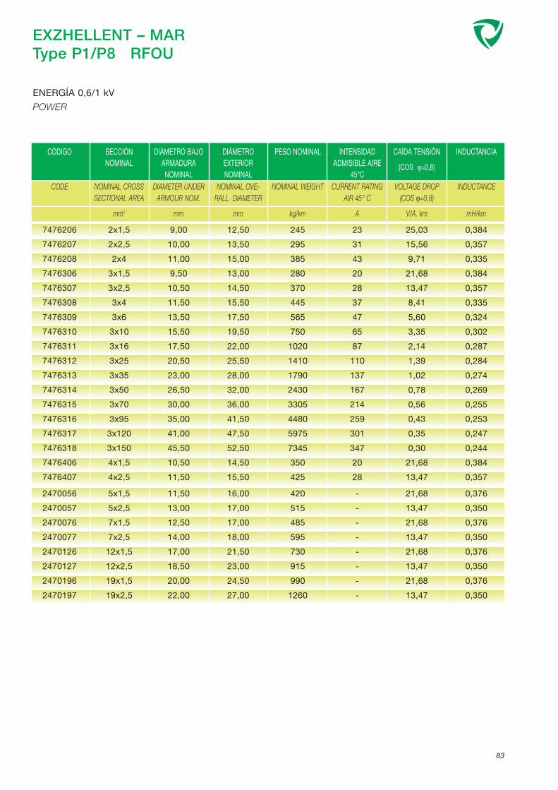
2470056
2470057
2470076
2470077
2470126
2470127
2470196
2470197
5x1,5
5x2,5
7x1,5
7x2,5
12x1,5
12x2,5
19x1,5
19x2,5
11,50
13,00
12,50
14,00
17,00
18,50
20,00
22,00
16,00
17,00
17,00
18,00
21,50
23,00
24,50
27,00
420
515
485
595
730
915
990
1260
-
-
-
-
-
-
-
-
21,68
13,47
21,68
13,47
21,68
13,47
21,68
13,47
0,376
0,350
0,376
0,350
0,376
0,350
0,376
0,350
EXZHELLENT – MARType P1/P8 RFOU
83
ENERGÍA 0,6/1 kV
POWER
CÓDIGO SECCIÓN NOMINAL
DIÁMETRO BAJOARMADURANOMINAL
DIÁMETROEXTERIORNOMINAL
PESO NOMINAL INTENSIDADADMISIBLE AIRE
45°C
CAÍDA TENSIÓN
(COS ϕ=0,8)
INDUCTANCIA
CODE NOMINAL CROSSSECTIONAL AREA
mm2
DIAMETER UNDERARMOUR NOM.
mm
NOMINAL OVE-RALL DIAMETER
mm
NOMINAL WEIGHT
kg/km
CURRENT RATINGAIR 45° C
A
VOLTAGE DROP (COS ϕ=0,8)
V/A. km
INDUCTANCE
mH/km
7476206
7476207
7476208
7476306
7476307
7476308
7476309
7476310
7476311
7476312
7476313
7476314
7476315
7476316
7476317
7476318
7476406
7476407
2x1,5
2x2,5
2x4
3x1,5
3x2,5
3x4
3x6
3x10
3x16
3x25
3x35
3x50
3x70
3x95
3x120
3x150
4x1,5
4x2,5
9,00
10,00
11,00
9,50
10,50
11,50
13,50
15,50
17,50
20,50
23,00
26,50
30,00
35,00
41,00
45,50
10,50
11,50
12,50
13,50
15,00
13,00
14,50
15,50
17,50
19,50
22,00
25,50
28,00
32,00
36,00
41,50
47,50
52,50
14,50
15,50
245
295
385
280
370
445
565
750
1020
1410
1790
2430
3305
4480
5975
7345
350
425
23
31
43
20
28
37
47
65
87
110
137
167
214
259
301
347
20
28
25,03
15,56
9,71
21,68
13,47
8,41
5,60
3,35
2,14
1,39
1,02
0,78
0,56
0,43
0,35
0,30
21,68
13,47
0,384
0,357
0,335
0,384
0,357
0,335
0,324
0,302
0,287
0,284
0,274
0,269
0,255
0,253
0,247
0,244
0,384
0,357

EXZHELLENT – MARType P1/P8 TFOU
IEC 60092-351 IEC 60754-1 IEC 60332-1IEC 60092-353 IEC 60754-2 IEC 60332-3-22IEC 60092-359 IEC 61034NEK 606:2004
1.- CONDUCTOR:
Cobre estañado recocido clase 2.
IEC 60228.
2.- AISLAMIENTO:
Polietileno reticulado LSF (HF XLPE).
IEC 60092-351.
Identificación de conductores:ver página 72.
3.- ASIENTO:
Compuesto libre de halógenos.
4.- ARMADURA:
Trenza de alambres de cobre estañado.
5.- CUBIERTA EXTERIOR:
Compuesto termoestable resistente a los fangos, tipo SHF Mud.
IEC 60092-359.
1.- CONDUCTOR:
Tinned copper, stranded class 2.
IEC 60228.
2.- INSULATION:
Cross-linked polyethylene LSF (HF XLPE).
IEC 60092-351.
Core identification: seepage 72.
3.- BEDDING:
Halogen free compound.
4.- BRAID ARMOUR:
Tinned copper wire braid.
5.- OUTER SHEATH:
Thermoset compound mud resistant type SHF Mud.
IEC 60092-359.
Armoured cables for installation in offshore applicationswith special performances on flame spread and low emis-sion of smoke and fumes.
Halogen free, oil and mud resistant.
84
ENERGÍA 0,6/1 kV
POWER
CONSTRUCCIÓN: CONSTRUCTION:
NORMAS / STANDARDS:
MAIN USES AND FEATURES:
Cables armados para instalación en plataformas conespeciales características de no propagación del incen-dio y reducida emisión de humos opacos, gases tóxicosy corrosivos.
Libre de halógenos, resistente a los aceites y fangos.
APLICACIONES Y CARACTERÍSTICAS PRINCIPALES:
CARACTERÍSTICAS DE DISEÑO: DESIGN CHARACTERISTICS:
Temperatura máxima del conductor en servicio perma-nente 90°C
Tensión nominal: 0,6/1 (1,2) kV.
Max. rated conductor temperature in normal operation:90°C.
Rated voltage: 0,6/1 (1,2) kV.
1
2
3
4
5

EXZHELLENT – MARType P1/P8 TFOU
85
ENERGÍA 0,6/1 kV
POWER
CÓDIGO SECCIÓN NOMINAL
DIÁMETRO BAJOARMADURANOMINAL
DIÁMETROEXTERIORNOMINAL
PESO NOMINAL INTENSIDADADMISIBLE AIRE
45°C
CAÍDA TENSIÓN
(COS ϕ=0,8)
INDUCTANCIA
CODE NOMINAL CROSSSECTIONAL AREA
mm2
DIAMETER UNDERARMOUR NOM.
mm
NOMINAL OVE-RALL DIAMETER
mm
NOMINAL WEIGHT
kg/km
CURRENT RATINGAIR 45° C
A
VOLTAGE DROP (COS ϕ=0,8)
V/A. km
INDUCTANCE
mH/km
7472206
7472207
7472208
7472306
7472307
7472308
7472309
7472310
7472311
7472312
7472313
7472314
7472315
7472316
7472317
7472318
7472406
7472407
2472056
2472057
2472076
2472077
2472126
2472127
2472196
2472197
2x1,5
2x2,5
2x4
3x1,5
3x2,5
3x4
3x6
3x10
3x16
3x25
3x35
3x50
3x70
3x95
3x120
3x150
4x1,5
4x2,5
5x1,5
5x2,5
7x1,5
7x2,5
12x1,5
12x2,5
19x1,5
19x2,5
8,00
8,50
9,50
8,50
9,00
10,00
12,00
15,00
16,00
19,50
23,00
25,00
29,00
32,50
38,50
43,50
9,00
10,00
10,00
11,00
11,00
12,00
14,50
16,00
17,00
19,00
11,00
12,00
13,00
11,50
12,50
13,50
15,50
19,00
20,50
24,00
28,00
30,00
34,50
39,00
45,50
50,00
12,50
13,50
13,50
14,50
14,50
16,00
18,50
20,50
21,50
23,50
200
240
300
225
270
345
450
700
945
1295
1775
2245
3130
4315
5630
6945
255
320
305
360
355
490
575
745
780
1015
23
31
43
20
28
37
47
65
87
110
137
167
214
259
301
347
20
28
-
-
-
-
-
-
-
-
25,02
15,55
9,70
21,67
13,46
8,40
5,59
3,34
2,14
1,38
1,02
0,77
0,56
0,42
0,35
0,30
21,67
13,46
21,67
13,46
21,67
13,46
21,67
13,46
21,67
13,46
0,345
0,322
0,304
0,345
0,322
0,304
0,298
0,276
0,269
0,269
0,256
0,254
0,245
0,238
0,236
0,235
0,345
0,322
0,345
0,322
0,345
0,322
0,345
0,322
0,345
0,322

EXZHELLENT – MARType P18 RU
IEC 60092-351 IEC 60754-1 IEC 60332-1IEC 60092-353 IEC 60754-2 IEC 60332-3-22IEC 60092-359 IEC 61034NEK 606:2004
1.- CONDUCTOR:
Cobre estañado recocido clase 2.
IEC 60228.
2.- AISLAMIENTO:
Etileno Propileno LSF (EPR).
IEC 60092-351.
Identificación de conductores:ver página 72.
3.- CUBIERTA EXTERIOR:
Compuesto termoestable tipoSHF2.
IEC 60092-359.
1.- CONDUCTOR:
Tinned copper, stranded class 2.
IEC 60228.
2.- INSULATION:
Ethylene Propylene Rubber LSF(EPR).
IEC 60092-351.
Core identification: see page 72.
3.- OUTER SHEATH:
Thermoset compound type SHF2.
IEC 60092-359.
Unarmoured cables for installation in offshore applicationswith special performances on flame spread and low emis-sion of smoke and fumes.
Oil resistant.
86
ENERGÍA 0,6/1 kV
POWER
CONSTRUCCIÓN: CONSTRUCTION:
NORMAS / STANDARDS:
MAIN USES AND FEATURES:
Cables no armados para instalación en plataformas conespeciales características de no propagación del incen-dio y reducida emisión de humos opacos, gases tóxicosy corrosivos.
Resistente a los aceites.
APLICACIONES Y CARACTERÍSTICAS PRINCIPALES:
1
CARACTERÍSTICAS DE DISEÑO: DESIGN CHARACTERISTICS:
Temperatura máxima del conductor en servicio perma-nente 90°C
Tensión nominal: 0,6/1 (1,2) kV.
Max. rated conductor temperature in normal operation:90°C.
Rated voltage: 0,6/1 (1,2) kV.
3
2

EXZHELLENT – MARType P18 RU
87
ENERGÍA 0,6/1 kV
POWER
CÓDIGO SECCIÓN NOMINAL
DIÁMETROEXTERIOR
APROX.
PESO APROX. INTENSIDAD ADMISIBLE AIRE
45°C
CAÍDA TENSIÓN
(COS ϕ=0,8)
INDUCTANCIA
CODE NOMINAL CROSSECTION
mm2
OUTER DIAMETERAPPROX.
mm
APPROX. WEIGHT
kg/km
CURRENT RATING AIR45° C
A
VOLTAGE DROP (COS ϕ=0,8)
V/A. km
INDUCTANCE
mH/km
7479206 2x1,5 9,50 125,00 16 21,68 0,38
7479207 2x2,5 10,00 160,00 22 13,47 0,36
7479208 2x4 11,00 205,00 29 8,41 0,34
7479306 3x1,5 10,00 150,00 14 21,68 0,38
7479307 3x2,5 10,50 190,00 19 13,47 0,36
7479308 3x4 12,00 260,00 25 8,41 0,34
7479309 3x6 13,50 345,00 33 5,57 0,22
7479310 3x10 16,00 505,00 46 3,32 0,22
7479311 3x16 18,00 715,00 61 2,12 0,22
7479312 3x25 21,50 1080,00 81 1,37 0,22
7479313 3x35 24,00 1430,00 99 1,01 0,21
7479314 3x50 28,00 2105,00 124 0,76 0,21
7479315 3x70 34,00 2865,00 153 0,54 0,20
7479316 3x95 39,00 3845,00 185 0,41 0,20
7479317 3x120 43,00 4745,00 214 0,34 0,20
7479318 3x150 47,50 5820,00 246 0,29 0,20
7479406 4x1,5 10,50 180,00 13 21,68 0,38
7479407 4x2,5 12,00 235,00 17 13,47 0,36
7479408 4x4 13,00 315,00 23 8,41 0,34
7479409 4x6 15,50 435,00 30 5,57 0,22
7479410 4x10 17,50 625,00 42 3,32 0,22
7479411 4x16 20,00 890,00 55 2,12 0,22
7479412 4x25 24,00 1360,00 73 1,37 0,22
7479413 4x35 27,00 1810,00 90 1,01 0,21
7479414 4x50 33,50 2670,00 113 0,76 0,21

EXZHELLENT – MARType RFOU
IEC 60092-351 IEC 60754-1 IEC 60332-1IEC 60092-354 IEC 60754-2 IEC 60332-3-22IEC 60092-359 IEC 61034NEK 606:2004
1.- CONDUCTOR: Cobre estañado recocido clase 2.IEC 60228.
2.- SEMICONDUCTOR INTERIOR:
3.- AISLAMIENTO:Etileno Propileno LSF (EPR).IEC 60092-351.
4.- APANTALLADO: Capa semiconductora y trenza de cobre estañado.
Identificación de conductores:ver página 72.
5.- ASIENTO: Compuesto libre de halógenos.
6.- ARMADURA: Trenza de alambres de cobre estañado.
7.- CUBIERTA EXTERIOR:Compuesto termoestable tipo
SHF2.IEC 60092-359.
1.- CONDUCTOR: Tinned copper, stranded class 2.IEC 60228.
2.- CONDUCTOR SCREENING: Semiconducting material.
3.- INSULATION: Ethylene Propylene Rubber LSF(EPR).IEC 60092-351.
4.- INSULATION SCREENING: Semiconducting material and tinned copper wire braid.Core identification: see page 72.
5.- BEDDING: Halogen free compound.
6.- BRAID ARMOUR: Tinned copper wire braid.
7.- OUTER SHEATH: Thermoset compound type SHF2.IEC 60092-359.
Medium voltage power cables for installation in offshoreapplications with special performances on flame spreadand low emission of smoke and fumes.
Oil resistant.
88
ENERGÍA MT
POWER MV
CONSTRUCCIÓN: CONSTRUCTION:
NORMAS / STANDARDS:
MAIN USES AND FEATURES:
Cables de media tensión para instalación en platafor-mas con especiales características de no propagacióndel incendio y reducida emisión de humos opacos,gases tóxicos y corrosivos.
Resistente a los aceites.
APLICACIONES Y CARACTERÍSTICAS PRINCIPALES:
CARACTERÍSTICAS DE DISEÑO: DESIGN CHARACTERISTICS:
Temperatura máxima del conductor en servicio perma-nente 90°C
Tensión nominal: 6 a 20 kV.
Max. rated conductor temperature in normal operation:90°C.
Rated voltage: 6 to 20 kV.
1234
5
6
7

EXZHELLENT – MARType RFOU
89
7480114748011574801167480117748011874801207480314748031574803167480317
1x501x701x95
1x1201x1501x240
3x50/253x70/353x95/50
3x120/60
20,0021,5023,5025,0026,5031,0041,5045,0048,0052,00
25,0026,5028,0030,0031,5036,5048,5052,0055,0060,00
1210147517752090240534954240517062607495
171221271316367502159203246286
0,1320,1250,1180,1140,1100,1020,1150,1090,1020,098
0,2830,3220,3590,3990,4320,5260,2880,3270,3590,399
7481114748111574811167481117748111874811207481314748131574813167481317
1x501x701x95
1x1201x1501x240
3x50/253x70/353x95/50
3x120/60
21,027,5
24,0026,0027,5031,5042,5046,0053,0054,00
26,0027,5029,5031,0032,5037,0049,5053,0061,0062,00
1265152518552165248535654395530068057750
171221271316367502159203246286
0,1350,1260,1210,1150,1110,1040,1170,1090,1040,100
0,2570,2880,3240,3590,3890,4720,2570,2880,3240,359
7482114748211574821167482117748211874821207482314748231574823167482317
1x501x701x95
1x1201x1501x240
3x50/253x70/353x95/50
3x120/60
23,0024,5026,5028,5030,0034,0052,0054,0058,5061,50
28,0030,0031,5034,0035,5040,0059,5062,5067,0070,00
1430169520352380273038705490634577008865
171221271316367502159203246286
0,1400,1320,1260,1210,1170,1090,1240,1160,1100,105
0,2080,2330,2600,2870,3090,3730,2120,2330,2600,287
Type P3 RFOUENERGIA 6/10 kV - POWER
Type P4 RFOUENERGIA 8,7/15 kV - POWER
(*) Cables unipolares, instalados en formación trebol.(*) Single core cables, installed in trefoil configuration.
Type P2 RFOUENERGIA 3,6/6 kV - POWER
7483114748311574831167483117748311874831207483314748331574833167483317
1x501x701x95
1x1201x1501x240
3x50/253x70/353x95/50
3x120/60
25,5026,5029,0030,5032,0036,5052,5056,0060,0063,50
30,5032,0034,5036,0038,5043,5060,5064,0068,5072,50
1580186522402560299542405820677581409405
171221271316367502159203246286
0,1450,1360,1310,1250,1210,1130,1300,1200,1160,111
0,1810,2010,2230,2460,2640,3160,1810,2010,2230,246
Type P19 RFOUENERGIA 12/20 kV - POWER
CÓDIGO SECCIÓN NOMINAL
DIÁMETRO BAJOARMADURANOMINAL
DIÁMETRO EXTE-RIOR NOMINAL
PESO NOMINAL INTENSIDADADMISIBLE AIRE
45°C
REACTANCIAINDUCTIVA
CAPACIDAD
CODE NOMINAL CROSSSECTIONAL AREA
mm2
DIAMETER UNDERARMOUR NOM.
mm
NOMINAL OVE-RALL DIAMETER
mm
NOMINAL WEIGHT
kg/km
CURRENT RATINGAIR 45° C
(*) A
INDUCTIVEREACTANCE
ohm/km
CAPACITANCE
µF/km

90
EXZHELLENT – MARType RFOU
IEC 60092-351 IEC 60754-1 IEC 60332-1IEC 60092-354 IEC 60754-2 IEC 60332-3-22IEC 60092-359 IEC 61034NEK 606:2004
1.- CONDUCTOR: Cobre estañado recocido clase 2.IEC 60228.
2.- SEMICONDUCTOR INTERIOR:
3.- AISLAMIENTO:Etileno Propileno LSF (EPR).IEC 60092-351.
4.- APANTALLADO: Capa semiconductora y trenza de cobre estañado.Identificación de conductores:ver página 72.
5.- ASIENTO: Compuesto libre de halógenos.
6.- ARMADURA: Trenza de alambres de cobre estañado.
7.- CUBIERTA EXTERIOR:Compuesto termoestable
resistente a los fangos, tipo SHF Mud.IEC 60092-359.
1.- CONDUCTOR: Tinned copper, stranded class 2.IEC 60228.
2.- CONDUCTOR SCREENING: Semiconducting material.
3.- INSULATION: Ethylene Propylene Rubber LSF(EPR).IEC 60092-351.
4.- INSULATION SCREENING: Semiconducting material and tinned copper wire braid.Core identification: seepage 72.
5.- BEDDING: Halogen free compound.
6.- BRAID ARMOUR: Tinned copper wire braid.
7.- OUTER SHEATH: Thermoset compound mud resistant type SHF Mud.IEC 60092-359.
Medium voltage power armoured cables for installation inoffshore applications with special performances on flamespread and low emission of smoke and fumes.
Halogen free, oil and mud resistant.
ENERGÍA MT
POWER MV
CONSTRUCCIÓN: CONSTRUCTION:
NORMAS / STANDARDS:
MAIN USES AND FEATURES:
Cables de media tensión para instalación en platafor-mas con especiales características de no propagacióndel incendio y reducida emisión de humos opacos,gases tóxicos y corrosivos.
Libre de halógenos, resistente a los aceites y fangos.
APLICACIONES Y CARACTERÍSTICAS PRINCIPALES:
CARACTERÍSTICAS DE DISEÑO: DESIGN CHARACTERISTICS:
Temperatura máxima del conductor en servicio perma-nente 90°C
Tensión nominal: 6 a 20 kV.
Max. rated conductor temperature in normal operation:90°C.
Rated voltage: 6 to 20 kV.
12345
6
7

91
EXZHELLENT – MARType RFOU
7484114748411574841167484117748411874841207484314748431574843167484317
1x501x701x95
1x1201x1501x240
3x50/253x70/353x95/50
3x120/60
20,0021,5023,5025,0026,5031,0041,5045,0048,0052,00
25,0026,5028,0030,0031,5036,5048,5052,0055,0060,00
1210147517752090240534954240517062607495
171221271316367502159203246286
0,1320,1250,1180,1140,1100,1020,1150,1090,1020,098
0,2830,3220,3590,3990,4320,5260,2880,3270,3590,399
7485114748511574851167485117748511874851207485314748531574853167485317
1x501x701x95
1x1201x1501x240
3x50/253x70/353x95/50
3x120/60
21,027,5
24,0026,0027,5031,5042,5046,0053,0054,00
26,0027,5029,5031,0032,5037,0049,5053,0061,0062,00
1265152518552165248535654395530068057750
171221271316367502159203246286
0,1350,1260,1210,1150,1110,1040,1170,1090,1040,100
0,2570,2880,3240,3590,3890,4720,2570,2880,3240,359
7486114748611574861167486117748611874861207486314748631574863167486317
1x501x701x95
1x1201x1501x240
3x50/253x70/353x95/50
3x120/60
23,0024,5026,5028,5030,0034,0052,0054,0058,5061,50
28,0030,0031,5034,0035,5040,0059,5062,5067,0070,00
1430169520352380273038705490634577008865
171221271316367502159203246286
0,1400,1320,1260,1210,1170,1090,1240,1160,1100,105
0,2080,2330,2600,2870,3090,3730,2120,2330,2600,287
Type P3/P10 RFOUENERGIA 6/10 kV - POWER
Type P4/P11 RFOUENERGIA 8,7/15 kV - POWER
(*) Cables unipolares, instalados en formación trebol.(*) Single core cables, installed in trefoil configuration.
Type P2/P9 RFOUENERGIA 3,6/6 kV - POWER
7487114748711574871167487117748711874871207487314748731574873167487317
1x501x701x95
1x1201x1501x240
3x50/253x70/353x95/50
3x120/60
25,5026,5029,0030,5032,0036,5052,5056,0060,0063,50
30,5032,0034,5036,0038,5043,5060,5064,0068,5072,50
1580186522402560299542405820677581409405
171221271316367502159203246286
0,1450,1360,1310,1250,1210,1130,1300,1200,1160,111
0,1810,2010,2230,2460,2640,3160,1810,2010,2230,246
Type P19/P21RFOUENERGIA 12/20 kV - POWER
CÓDIGO SECCIÓN NOMINAL
DIÁMETRO BAJOARMADURANOMINAL
DIÁMETRO EXTE-RIOR NOMINAL
PESO NOMINAL INTENSIDADADMISIBLE AIRE
45°C
REACTANCIAINDUCTIVA
CAPACIDAD
CODE NOMINAL CROSSSECTIONAL AREA
mm2
DIAMETER UNDERARMOUR NOM.
mm
NOMINAL OVE-RALL DIAMETER
mm
NOMINAL WEIGHT
kg/km
CURRENT RATINGAIR 45° C
(*) A
INDUCTIVEREACTANCE
ohm/km
CAPACITANCE
µF/km

EXZHELLENT – MARType S1 RFOU (i)
IEC 60092-351 IEC 60754-1 IEC 60332-1IEC 60092-359 IEC 60754-2 IEC 60332-3-22IEC 60092-376 IEC 61034NEK 606:2004
1.- CONDUCTOR:
Cobre estañado recocido clase 2.
IEC 60228.
2.- AISLAMIENTO:
Etileno Propileno LSF (EPR).
IEC 60092-351.
Identificación de conductores:ver página 73.
3.- PANTALLA INDIVIDUAL:
Cinta de cobre poliéster con conductor de drenaje.
4.- ASIENTO:
Compuesto libre de halógenos.
5.- ARMADURA:
Trenza de alambres de cobre estañado.
6.- CUBIERTA EXTERIOR:
Compuesto termoestable tipoSHF2.
IEC 60092-359.
1.- CONDUCTOR:
Tinned copper, stranded class 2.
IEC 60228.
2.- INSULATION:
Ethylene Propylene Rubber LSF(EPR).
IEC 60092-351.
Core identification: seepage 73.
3.- INDIVIDUAL SCREEN:
Copper polyester tape with drain wire.
4.- BEDDING:
Halogen free compound.
5.- BRAID ARMOUR:
Tinned copper wire braid.
6.- OUTER SHEATH:
Thermoset compound type SHF2.
IEC 60092-359.
Armoured, individually screened pairs/triples cables for ins-tallation in offshore applications with special performanceson flame spread and low emission of smoke and fumes.
Oil resistant.
92
INSTRUMENTACIÓN (pantalla individual, armado) 250 V
INSTRUMENTATION (individually screened, armoured)
CONSTRUCCIÓN: CONSTRUCTION:
NORMAS / STANDARDS:
MAIN USES AND FEATURES:
Cables armados multipares/multitríos apantallados indi-vidualmente para instalación en circuitos de control enplataformas con especiales características de no pro-pagación del incendio y reducida emisión de humosopacos, gases tóxicos y corrosivos.
Resistente a los aceites.
APLICACIONES Y CARACTERÍSTICAS PRINCIPALES:
CARACTERÍSTICAS DE DISEÑO: DESIGN CHARACTERISTICS:
Temperatura máxima del conductor en servicio perma-nente 90°C
Tensión nominal: 150/250 V.
Max. rated conductor temperature in normal operation:90°C.
Rated voltage: 150/250 V.
1
2
3
4
5
6

EXZHELLENT – MARType S1 RFOU (i)
93
INSTRUMENTACIÓN (pantalla individual, armado) 250 V
INSTRUMENTATION (individually screened, armoured)
CÓDIGO SECCIÓN NOMINAL
DIÁMETRO BAJOARMADURANOMINAL
DIÁMETROEXTERIORNOMINAL
PESO NOMINAL
CODE NOMINAL CROSSSECTIONAL AREA
mm2
DIAMETER UNDERARMOUR NOMINAL
mm
NOMINAL OVERALLDIAMETER
mm
NOMINAL WEIGHT
kg/km
4271015
4271016
4271025
4271026
4271045
4271046
4271085
4271086
4271125
4271126
4271165
4271166
4271245
4271246
4281015
4281016
4281025
4281026
4281045
4281046
4281085
4281086
4281125
4281126
4281165
4281166
1x2x1
1x2x1,5
2x2x1
2x2x1,5
4x2x1
4x2x1,5
8x2x1
8x2x1,5
12x2x1
12x2x1,5
16x2x1
16x2x1,5
24x2x1
24x2x1,5
1x3x1
1x3x1,5
2x3x1
2x3x1,5
4x3x1
4x3x1,5
8x3x1
8x3x1,5
12x3x1
12x3x1,5
16x3x1
16x3x1,5
8,50
8,50
13,50
14,00
16,00
16,50
21,00
22,00
26,00
27,00
29,50
30,50
37,00
38,50
8,50
9,00
15,00
15,50
18,00
18,50
24,00
24,50
29,50
30,50
33,00
34,50
11,50
12,00
18,00
18,00
20,00
21,00
26,00
27,00
31,00
32,50
35,00
36,50
43,50
45,50
12,00
12,50
19,50
20,00
22,00
23,00
29,00
29,50
35,00
36,50
39,00
41,00
225
245
515
540
605
680
975
1095
1335
1550
1725
1930
2525
2915
250
265
610
675
755
855
1220
1385
1740
1995
2270
2580
Constantes eléctricas y propiedades características ver página 74
Electrical parameters and characteristic properties see page 74

EXZHELLENT-MARType S2 RFOU (c)
IEC 60092-351 IEC 60754-1 IEC 60332-1IEC 60092-359 IEC 60754-2 IEC 60332-3-22IEC 60092-376 IEC 61034NEK 606:2004
1.- CONDUCTOR:
Cobre estañado recocido clase 2.
IEC 60228.
2.- AISLAMIENTO:
Etileno Propileno LSF (EPR). IEC 60092-351.
Identificación de conductores:ver página 73.
3.- PANTALLA COLECTIVA:
Cinta de cobre poliéster con conductor de drenaje.
4.- ASIENTO:
Compuesto libre de halógenos.
5.- ARMADURA:
Trenza de alambres de cobre estañado.
6.- CUBIERTA EXTERIOR:
Compuesto termoestable tipoSHF2.
IEC 60092-359.
1.- CONDUCTOR:
Tinned copper, stranded class 2.
IEC 60228.
2.- INSULATION:
Ethylene Propylene Rubber LSF(EPR).
IEC 60092-351.
Core identification: seepage 73.
3.- COLLECTIVE SCREEN:
Copper polyester tape with drain wire.
4.- BEDDING:
Halogen free compound.
5.- BRAID ARMOUR:
Tinned copper wire braid.
6.- OUTER SHEATH:
Thermoset compound type SHF2.
IEC 60092-359.
Armoured, colletively screened pairs/triples cables for ins-tallation in offshore applications with special performanceson flame spread and low emission of smoke and fumes.
Oil resistant.
94
INSTRUMENTACIÓN (pantalla colectiva, armado) 250 V
INSTRUMENTATION (collectively screened, armoured)
CONSTRUCCIÓN: CONSTRUCTION:
NORMAS / STANDARDS:
MAIN USES AND FEATURES:
Cables armados multipares/multitríos apantalladocolectivamente para instalación de circuitos de controlen plataformas con especiales características de nopropagación del incendio y reducida emisión de humosopacos, gases tóxicos y corrosivos.
Resistente a los aceites.
APLICACIONES Y CARACTERÍSTICAS PRINCIPALES:
CARACTERÍSTICAS DE DISEÑO: DESIGN CHARACTERISTICS:
Temperatura máxima del conductor en servicio perma-nente 90°C
Tensión nominal: 150/250 V.
Max. rated conductor temperature in normal operation:90°C.
Rated voltage: 150/250 V.
1
2
3
4
5
6

EXZHELLENT-MARType S2 RFOU (c)
95
INSTRUMENTACIÓN (pantalla colectiva, armado) 250 V
INSTRUMENTATION (collectively screened, armoured
CÓDIGO SECCIÓN NOMINAL
DIÁMETRO BAJOARMADURANOMINAL
DIÁMETROEXTERIORNOMINAL
PESO NOMINAL
CODE NOMINAL CROSSSECTIONAL AREA
mm2
DIAMETER UNDERARMOUR NOMINAL
mm
NOMINAL OVERALLDIAMETER
mm
NOMINAL WEIGHT
kg/km
4272025
4272026
4272045
4272046
4272085
4272086
4272125
4272126
4272165
4272166
4272245
4272246
4282025
4282026
4282045
4282046
4282085
4282086
4282125
4282126
4282165
4282166
2x2x1
2x2x1,5
4x2x1
4x2x1,5
8x2x1
8x2x1,5
12x2x1
12x2x1,5
16x2x1
16x2x1,5
24x2x1
24x2x1,5
2x3x1
2x3x1,5
4x3x1
4x3x1,5
8x3x1
8x3x1,5
12x3x1
12x3x1,5
16x3x1
16x3x1,5
9,50
10,00
13,50
14,00
16,50
19,50
20,50
21,50
22,00
26,00
28,50
34,00
10,50
13,50
12,50
14,50
15,50
20,50
19,00
20,00
20,00
24,00
13,00
13,50
17,50
18,00
21,50
24,50
25,50
26,50
27,00
31,00
34,50
40,50
14,50
17,50
16,50
19,00
20,00
25,50
24,50
25,00
25,50
29,00
285
305
475
525
720
880
975
1140
1195
1465
1710
2230
360
470
530
640
855
1105
1200
1395
1460
1780
- El cable de dos pares está cableado en cuadrete-estrella, con los conductores situados diametralmente opuestos, ej. Par 1- Azul-Negro. Par 2 Marrón-Gris.
- Constantes eléctricas y propiedades características, ver página 74
- 2 pair cables laid up in star quad configuration with the pairs identified by diametrically opposite cores, i.e. Pair 1 - Blueand Black Cores Pair 2 - Brown and Grey Cores.
- Electrical parametres and characteritic properties, see page 74

EXZHELLENT – MARType S11 RU(i)
IEC 60092-351 IEC 60754-1 IEC 60332-1IEC 60092-359 IEC 60754-2 IEC 60332-3-22IEC 60092-376 IEC 61034NEK 606:2004
1.- CONDUCTOR:
Cobre estañado recocido clase 2.
IEC 60228.
2.- AISLAMIENTO:
Etileno Propileno LSF (EPR).
IEC 60092-351.
Identificación de conductores:ver página 73.
3.- PANTALLA INDIVIDUAL:
Cinta de cobre poliéster con conductor de drenaje.
4.- CUBIERTA EXTERIOR:
Compuesto termoestable tipoSHF2.
IEC 60092-359.
1.- CONDUCTOR:
Tinned copper, stranded class 2.
IEC 60228.
2.- INSULATION:
Ethylene Propylene Rubber LSF(EPR).
IEC 60092-351.
Core identification: seepage 73.
3.- INDIVIDUAL SCREEN:
Copper polyester tape with drain wire.
4.- OUTER SHEATH:
Thermoset compound type SHF2.
IEC 60092-359.
Unarmoured, individually screened pairs/triples cables forinstallation in offshore applications with special performan-ces on flame spread and low emission of smoke andfumes.
Oil resistant.
96
INSTRUMENTACIÓN (pantalla individual) 250 V
INSTRUMENTATION (individually screened)
CONSTRUCCIÓN: CONSTRUCTION:
NORMAS / STANDARDS:
MAIN USES AND FEATURES:
Cables no armados multipares/multitríos apantalladosindividualmente para instalación en circuitos de controlen plataformas con especiales características de nopropagación del incendio y reducida emisión de humosopacos, gases tóxicos y corrosivos.
Resistente a los aceites.
APLICACIONES Y CARACTERÍSTICAS PRINCIPALES:
1
CARACTERÍSTICAS DE DISEÑO: DESIGN CHARACTERISTICS:
Temperatura máxima del conductor en servicio perma-nente 90°C
Tensión nominal: 150/250 V.
Max. rated conductor temperature in normal operation:90°C.
Rated voltage: 150/250 V.
2
3
4

EXZHELLENT – MARType S11 RU(i)
97
INSTRUMENTACIÓN (pantalla individual) 250 V
INSTRUMENTATION (individually screened)
CÓDIGO SECCIÓN NOMINAL
DIÁMETROEXTERIOR
APROX.
PESO APROX.
CODE NOMINAL CROSSSECTION
mm2
OUTER DIAMETERAPPROX.
mm
APPROX. WEIGHT
kg/km
4267014 1x2x0,75 7,00 90
4267016 1x2x1,5 8,00 125
4267017 1x2x2,5 9,00 160
4267024 2x2x0,75 11,50 185
4267026 2x2x1,5 13,50 230
4267027 2x2x2,5 15,00 295
4267034 3x2x0,75 12,00 200
4267036 3x2x1,5 14,50 295
4267037 3x2x2,5 16,00 390
4267074 7x2x0,75 16,50 410
4267076 7x2x1,5 19,50 610
4267077 7x2x2,5 22,00 815
4267124 12x2x0,75 22,00 705
4267126 12x2x1,5 26,50 1030
4267127 12x2x2,5 29,50 1380
4267194 19x2x0,75 26,00 1075
4267196 19x2x1,5 31,50 1570
4267197 19x2x2,5 35,50 2105
4267244 24x2x0,75 31,00 1315
4267246 24x2x1,5 37,50 2020
4267247 24x2x2,5 42,00 2720
4267274 27x2x0,75 31,50 1440
4267276 27x2x1,5 38,50 2220
4267277 27x2x2,5 43,00 2995
- Constantes eléctricas y propiedades características, ver página 74
- Electrical parametres and characteritic properties, see page 74

EXZHELLENT-MARType S12 RU(c)
IEC 60092-351 IEC 60754-1 IEC 60332-1IEC 60092-359 IEC 60754-2 IEC 60332-3-22IEC 60092-376 IEC 61034NEK 606:2004
1.- CONDUCTOR:
Cobre estañado recocido clase 2.
IEC 60228.
2.- AISLAMIENTO:
Etileno Propileno LSF (EPR). IEC 60092-351.
Identificación de conductores:ver página 73.
3.- PANTALLA COLECTIVA:
Cinta de cobre poliéster con conductor de drenaje.
4.- CUBIERTA EXTERIOR:
Compuesto termoestable tipoSHF2.
IEC 60092-359.
1.- CONDUCTOR:
Tinned copper, stranded class 2.
IEC 60228.
2.- INSULATION:
Ethylene Propylene Rubber LSF(EPR).
IEC 60092-351.
Core identification: seepage 73.
3.- COLLECTIVE SCREEN:
Copper polyester tape with drain wire.
4.- OUTER SHEATH:
Thermoset compound type SHF2.
IEC 60092-359.
Unarmoured, colletively screened pairs/triples cables forinstallation in offshore applications with special performan-ces on flame spread and low emission of smoke andfumes.
Oil resistant.
98
INSTRUMENTACIÓN (pantalla colectiva) 250 V
INSTRUMENTATION (collectively screened)
CONSTRUCCIÓN: CONSTRUCTION:
NORMAS / STANDARDS:
MAIN USES AND FEATURES:
Cables no armados multipares/multitríos apantalladocolectivamente para instalación de circuitos de controlen plataformas con especiales características de nopropagación del incendio y reducida emisión de humosopacos, gases tóxicos y corrosivos.
Resistente a los aceites.
APLICACIONES Y CARACTERÍSTICAS PRINCIPALES:
1
CARACTERÍSTICAS DE DISEÑO: DESIGN CHARACTERISTICS:
Temperatura máxima del conductor en servicio perma-nente 90°C
Tensión nominal: 150/250 V.
Max. rated conductor temperature in normal operation:90°C.
Rated voltage: 150/250 V.
2
3
4

EXZHELLENT-MARType S12 RU(c)
99
INSTRUMENTACIÓN (pantalla colectiva) 250 V
INSTRUMENTATION (collectively screened)
CÓDIGO SECCIÓN NOMINAL
DIÁMETROEXTERIOR
APROX.
PESO APROX.
CODE NOMINAL CROSSSECTION
mm2
OUTER DIAMETERAPPROX.
mm
APPROX. WEIGHT
kg/km
4268024 2x2x0,75 11,50 155
4268026 2x2x1,5 14,00 220
4268027 2x2x2,5 15,50 285
4268034 3x2x0,75 12,50 185
4268036 3x2x1,5 15,00 280
4268037 3x2x2,5 17,00 370
4268074 7x2x0,75 16,50 345
4268076 7x2x1,5 20,00 540
4268077 7x2x2,5 22,50 720
4268124 12x2x0,75 22,00 575
4268126 12x2x1,5 27,00 895
4268127 12x2x2,5 30,50 1225
4268194 19x2x0,75 26,50 835
4268196 19x2x1,5 32,00 1320
4268197 19x2x2,5 36,50 1820
4268244 24x2x0,75 31,00 1070
4268246 24x2x1,5 38,00 1705
4268247 24x2x2,5 43,00 2365
4268274 27x2x0,75 32,00 1180
4268276 27x2x1,5 39,00 1860
4268277 27x2x2,5 44,00 2590
- El cable de dos pares está cableado en cuadrete-estrella, con los conductores situados diametralmente opuestos, ej. Par 1- Azul-Negro. Par 2 Marrón-Gris.
- Constantes eléctricas y propiedades características, ver página 74
- 2 pair cables laid up in star quad configuration with the pairs identified by diametrically opposite cores, i.e. Pair 1 - Blueand Black Cores Pair 2 - Brown and Grey Cores.
- Electrical parametres and characteritic properties, see page 74

EXZHELLENT – MARType S1/S5 RFOU(i)
IEC 60092-351 IEC 60754-1 IEC 60332-1IEC 60092-359 IEC 60754-2 IEC 60332-3-22IEC 60092-376 IEC 61034NEK 606:2004
1.- CONDUCTOR: Cobre estañado recocido clase 2.IEC 60228.
2.- AISLAMIENTO:Etileno Propileno LSF (EPR).IEC 60092-351.
Identificación de conductores:ver página 73.
3.- PANTALLA INDIVIDUAL: Cinta de cobre poliéster con conductor de drenaje.
4.- ASIENTO: Compuesto libre de halógenos.
5.- ARMADURA: Trenza de alambres de cobre estañado.
6.- CUBIERTA EXTERIOR:Compuesto termoestable resistente a los fangos tipo SHF Mud.IEC 60092-359.
1.- CONDUCTOR:
Tinned copper, stranded class 2.
IEC 60228.
2.- INSULATION:
Ethylene Propylene Rubber LSF(EPR).
IEC 60092-351.
Core identification: see page 73.
3.- INDIVIDUAL SCREEN:
Copper polyester tape with drain wire.
4.- BEDDING:
Halogen free compound.
5.- BRAID ARMOUR:
Tinned copper wire braid.
6.- OUTER SHEATH:
Thermoset compound mud resistant type SHF Mud.
IEC 60092-359.
Armoured, individually screened pairs/triples cables for ins-tallation in offshore applications with special performanceson flame spread and low emission of smoke and fumes.
Halogen free, oil and mud resistant.
100
INSTRUMENTACIÓN (pantalla individual, armado) 250 V
INSTRUMENTATION (individually screened, armoured)
CONSTRUCCIÓN: CONSTRUCTION:
NORMAS / STANDARDS:
MAIN USES AND FEATURES:
Cables armados multipares/multitríos apantallado indi-vidualmente para instalación de circuitos de control enplataformas con especiales características de no pro-pagación del incendio y reducida emisión de humosopacos, gases tóxicos y corrosivos.
Libre de halógenos, resistente a los aceites y fangos.
APLICACIONES Y CARACTERÍSTICAS PRINCIPALES:
CARACTERÍSTICAS DE DISEÑO: DESIGN CHARACTERISTICS:
Temperatura máxima del conductor en servicio perma-nente 90°C
Tensión nominal: 150/250 V.
Max. rated conductor temperature in normal operation:90°C.
Rated voltage: 150/250 V.
1
2
3
4
5
6

EXZHELLENT – MARType S1/S5 RFOU(i)
101
INSTRUMENTACIÓN (pantalla individual, armado) 250 V
INSTRUMENTATION (individually screened, armoured)
CÓDIGO SECCIÓN NOMINAL
DIÁMETRO BAJOARMADURANOMINAL
DIÁMETROEXTERIORNOMINAL
PESO NOMINAL
CODE NOMINAL CROSSSECTIONAL AREA
mm2
DIAMETER UNDERARMOUR NOMINAL
mm
NOMINAL OVERALLDIAMETER
mm
NOMINAL WEIGHT
kg/km
4273015
4273016
4273025
4273026
4273045
4273046
4273085
4273086
4273125
4273126
4273165
4273166
4273245
4273246
4283015
4283016
4283025
4283026
4283045
4283046
4283085
4283086
4283125
4283126
4283165
4283166
1x2x1
1x2x1,5
2x2x1
2x2x1,5
4x2x1
4x2x1,5
8x2x1
8x2x1,5
12x2x1
12x2x1,5
16x2x1
16x2x1,5
24x2x1
24x2x1
1x3x1
1x3x1,5
2x3x1
2x3x1,5
4x3x1
4x3x1,5
8x3x1
8x3x1,5
12x3x1
12x3x1,5
16x3x1
16x3x1,5
8,50
8,50
13,50
14,00
16,00
16,50
21,00
22,00
26,00
27,50
29,50
30,50
36,50
38,00
8,50
9,00
15,00
15,50
18,00
18,50
24,00
24,50
29,50
30,50
33,00
34,50
11,50
12,00
18,00
18,00
20,00
21,00
26,00
27,00
31,00
32,50
35,00
36,00
43,50
45,00
12,00
12,50
19,50
20,00
22,00
23,00
29,00
29,50
35,00
36,50
39,00
41,00
230
250
525
560
620
690
995
1095
1365
1560
1735
1935
2585
2865
255
280
630
690
770
1255
1255
1390
1785
2010
2285
2585
Constantes eléctricas y propiedades características ver página 74
Electrical parameters and characteristic properties see page 74

EXZHELLENT – MARType S2/S6 RFOU(c)
IEC 60092-351 IEC 60754-1 IEC 60332-1IEC 60092-359 IEC 60754-2 IEC 60332-3-22IEC 60092-376 IEC 61034NEK 606:2004
1.- CONDUCTOR:
Cobre estañado recocido clase 2.
IEC 60228.
2.- AISLAMIENTO:
Etileno Propileno LSF (EPR).
IEC 60092-351.
Identificación de conductores:ver página 73.
3.- PANTALLA COLECTIVA:
Cinta de cobre poliéster con conductor de drenaje.
4.- ASIENTO:
Compuesto libre de halógenos.
5.- ARMADURA:
Trenza de alambres de cobre estañado.
6.- CUBIERTA EXTERIOR:
Compuesto termoestable resistente a los fangos tipo SHF Mud.
IEC 60092-359.
1.- CONDUCTOR:
Tinned copper, stranded class 2.
IEC 60228.
2.- INSULATION:
Ethylene Propylene Rubber LSF(EPR).
IEC 60092-351.
Core identification: seepage 73.
3.- COLLECTIVE SCREEN:
Copper polyester tape with drain wire.
4.- BEDDING:
Halogen free compound.
5.- BRAID ARMOUR:
Tinned copper wire braid.
6.- OUTER SHEATH:
Thermoset compound mud resistant type SHF Mud.
IEC 60092-359.
Armoured, colectively screened pairs/triples cables for ins-tallation in offshore applications with special performanceson flame spread and low emission of smoke and fumes.
Halogen free, oil and mud resistant.
102
INSTRUMENTACIÓN (pantalla colectiva, armado) 250 V
INSTRUMENTATION (collectively screened, armoured
CONSTRUCCIÓN: CONSTRUCTION:
NORMAS / STANDARDS:
MAIN USES AND FEATURES:
Cables armados multipares/multitríos apantalladoscolectivamente para instalación de circuitos de controlen plataformas con especiales características de nopropagación del incendio y reducida emisión de humosopacos, gases tóxicos y corrosivos.
APLICACIONES Y CARACTERÍSTICAS PRINCIPALES:
CARACTERÍSTICAS DE DISEÑO: DESIGN CHARACTERISTICS:
Libre de halógenos, resistente a los aceites y fangos.
Temperatura máxima del conductor en servicio perma-nente 90°C
Max. rated conductor temperature in normal operation:90°C.
Rated voltage: 150/250 V.
1
2
3
4
5
6

EXZHELLENT – MARType S2/S6 RFOU(c)
103
INSTRUMENTACIÓN (pantalla colectiva, armado) 250 V
INSTRUMENTATION (collectively screened, armoured
CÓDIGO SECCIÓN NOMINAL
DIÁMETRO BAJOARMADURANOMINAL
DIÁMETROEXTERIORNOMINAL
PESO NOMINAL
CODE NOMINAL CROSSSECTIONAL AREA
mm2
DIAMETER UNDERARMOUR NOMINAL
mm
NOMINAL OVERALLDIAMETER
mm
NOMINAL WEIGHT
kg/km
4274025
4274026
4274045
4274046
4274085
4274086
4274125
4274126
4274165
4274166
4274245
4284246
4284025
4284026
4284045
4284046
4284085
4284086
4284125
4284126
4284165
42844166
2x2x1
2x2x1,5
4x2x1
4x2x1,5
8x2x1
8x2x1,5
12x2x1
12x2x1,5
16x2x1
16x2x1,5
24x2x1
24x2x1,5
2x3x1
2x3x1,5
4x3x1
4x3x1,5
8x3x1
8x3x1,5
12x3x1
12x3x1,5
16x3x1
16x3x1,5
9,50
10,00
13,50
14,00
16,50
17,50
20,50
21,50
22,00
22,50
28,50
29,50
10,50
12,00
12,50
14,50
15,50
18,00
19,00
20,00
20,00
24,00
13,00
13,50
17,50
18,00
21,00
22,00
25,50
26,50
27,00
28,00
34,50
36,00
14,50
16,00
16,50
19,00
20,00
23,00
24,50
25,00
25,50
29,50
285
315
480
535
725
825
1005
1145
1205
1385
1765
2135
365
435
535
645
865
1045
1210
1405
1465
1825
- El cable de dos pares está cableado en cuadrete-estrella, con los conductores situados diametralmente opuestos, ej. Par 1- Azul-Negro. Par 2 Marrón-Gris.
- Constantes eléctricas y propiedades características, ver página 74
- 2 pair cables laid up in star quad configuration with the pairs identified by diametrically opposite cores, i.e. Pair 1 - Blueand Black Cores Pair 2 - Brown and Grey Cores.
- Electrical parametres and characteritic properties, see page 74

EXZHELLENT – MARType P5 BFOU
IEC 60092-351 IEC 60754-1 IEC 60331-21IEC 60092-353 IEC 60754-2 IEC 60332-1IEC 60092-359 IEC 61034 IEC 60332-3-22NEK 606:2004
1.- CONDUCTOR:
Cobre estañado recocido clase 2.
IEC 60228.
2.- ENCINTADO DE MICA.
3.- AISLAMIENTO:
Etileno Propileno LSF (EPR).
IEC 60092-351.
Identificación de conductores:ver página 72.
4.- ASIENTO:
Compuesto libre de halógenos.
5.- ARMADURA:
Trenza de alambres de cobre estañado.
6.- CUBIERTA EXTERIOR:
Compuesto termoestable tipoSHF2.
IEC 60092-359.
1.- CONDUCTOR:
Tinned copper, stranded class 2.
IEC 60228.
2.- MICA TAPE.
3.- INSULATION:
Ethylene Propylene Rubber LSF(EPR).
IEC 60092-351.
Core identification: see page 72.
4.- BEDDING:
Halogen free compound.
5.- BRAID ARMOUR:
Tinned copper wire braid.
6.- OUTER SHEATH:
Thermoset compound type SHF2.
IEC 60092-359.
Armoured cables for installation in offshore applicationswith special performances on flame spread and low emis-sion of smoke and fumes.
Fire and oil resistant.
104
ENERGÍA 0,6/1kV
POWER
CONSTRUCCIÓN: CONSTRUCTION:
NORMAS / STANDARDS:
MAIN USES AND FEATURES:
Cables armados para instalación en plataformas conespeciales características de no propagación del incen-dio y reducida emisión de humos opacos, gases tóxicosy corrosivos.
Resistente al fuego y a los aceites.
APLICACIONES Y CARACTERÍSTICAS PRINCIPALES:
CARACTERÍSTICAS DE DISEÑO: DESIGN CHARACTERISTICS:
Temperatura máxima del conductor en servicio perma-nente 90°C
Tensión nominal: 0,6/1 (1,2) kV.
Max. rated conductor temperature in normal operation:90°C.
Rated voltage: 0,6/1 (1,2) kV
12
3
4
5
6

EXZHELLENT – MARType P5 BFOU
105
ENERGÍA 0,6/1kV
POWER
CÓDIGO SECCIÓN NOMINAL
DIÁMETRO BAJOARMADURANOMINAL
DIÁMETROEXTERIORNOMINAL
PESO NOMINAL INTENSIDADADMISIBLE AIRE
45°C
CAÍDA TENSIÓN
(COS ϕ=0,8)
INDUCTANCIA
CODE NOMINAL CROSSSECTIONAL AREA
mm2
DIAMETER UNDERARMOUR NOM.
mm
NOMINAL OVE-RALL DIAMETER
mm
NOMINAL WEIGHT
kg/km
CURRENT RATINGAIR 45° C
A
VOLTAGE DROP (COS ϕ=0,8)
V/A. km
INDUCTANCE
mH/km
7473206 2x1,5 10,00 13,50 275 16 21,69 0,41
7473207 2x2,5 10,50 15,00 355 23 13,48 0,38
7473208 2x4 11,50 16,00 415 30 8,42 0,35
7473306 3x1,5 10,50 14,50 345 14 21,69 0,41
7473307 3x2,5 11,50 15,50 400 20 13,48 0,38
7473308 3x4 12,50 16,50 475 26 8,42 0,35
7473309 3x6 13,50 18,00 580 34 5,60 0,33
7473310 3x10 15,50 20,00 770 47 3,35 0,31
7473311 3x16 17,50 22,00 1030 63 2,15 0,29
7473312 3x25 21,00 26,00 1450 83 1,39 0,29
7473313 3x35 23,00 28,50 1820 102 1,03 0,28
7473314 3x50 27,00 32,00 2430 128 0,78 0,27
7473315 3x70 30,50 36,00 3310 158 0,56 0,26
7473316 3x95 35,00 41,50 4485 191 0,43 0,26
7473317 3x120 41,50 48,50 6020 221 0,35 0,25
7473318 3x150 46,00 53,00 7365 254 0,30 0,25
7473406 4x1,5 11,50 15,50 390 13 21,69 0,41
7473407 4x2,5 12,50 16,50 460 18 13,48 0,38
2473056 5x1,5 13,00 17,00 470 - 21,69 0,41
2473057 5x2,5 14,00 18,50 555 - 13,48 0,38
2473076 7x1,5 14,00 18,50 540 - 21,69 0,41
2473077 7x2,5 15,00 19,50 650 - 13,48 0,38
2473126 12x1,5 18,50 23,50 820 - 21,69 0,41
2473127 12x2,5 20,50 25,00 995 - 13,48 0,38
2473196 19x1,5 22,00 27,00 1110 - 21,69 0,41

EXZHELLENT – MARType P5/P12 BFOU
IEC 60092-351 IEC 60754-1 IEC 60331-21IEC 60092-353 IEC 60754-2 IEC 60332-1IEC 60092-359 IEC 61034 IEC 60332-3-22NEK 606:2004
1.- CONDUCTOR:
Cobre estañado recocido clase 2.
IEC 60228.
2.- ENCINTADO DE MICA.
3.- AISLAMIENTO:
Etileno Propileno LSF (EPR).
IEC 60092-351.
Identificación de conductores:ver página 72.
4.- ASIENTO:
Compuesto libre de halógenos.
5.- ARMADURA:
Trenza de alambres de cobre estañado.
6.- CUBIERTA EXTERIOR:
Compuesto termoestable resistente a los fangos tipo SHF Mud.
IEC 60092-359.
1.- CONDUCTOR:
Tinned copper, stranded class 2.
IEC 60228.
2.- MICA TAPE.
3.- INSULATION:
Ethylene Propylene Rubber LSF(EPR).
IEC 60092-351.
Core identification: see page 72.
4.- BEDDING:
Halogen free compound.
5.- BRAID ARMOUR:
Tinned copper wire braid.
6.- OUTER SHEATH:
Thermoset compound mud resistant type SHF Mud.
IEC 60092-359.
Armoured cables for installation in offshore applicationswith special performances on flame spread and low emis-sion of smoke and fumes.
Halogen free, fire, oil and mud resistant.
106
ENERGÍA 0,6/1 kV
POWER
CONSTRUCCIÓN: CONSTRUCTION:
NORMAS / STANDARDS:
MAIN USES AND FEATURES:
Cables armados para instalación en plataformas conespeciales características de no propagación del incen-dio y reducida emisión de humos opacos, gases tóxicosy corrosivos.
Libre de halógenos, resistente al fuego, aceites y fan-gos.
APLICACIONES Y CARACTERÍSTICAS PRINCIPALES:
CARACTERÍSTICAS DE DISEÑO: DESIGN CHARACTERISTICS:
Temperatura máxima del conductor en servicio perma-nente 90°C
Tensión nominal: 0,6/1 (1,2) kV.
Max. rated conductor temperature in normal operation:90°C.
Rated voltage: 0,6/1 (1,2) kV.
12
3
4
5
6

EXZHELLENT – MARType P5/P12 BFOU
107
ENERGÍA 0,6/1 kV
POWER
CÓDIGO SECCIÓN NOMINAL
DIÁMETRO BAJOARMADURANOMINAL
DIÁMETROEXTERIORNOMINAL
PESO NOMINAL INTENSIDADADMISIBLE AIRE
45°C
CAÍDA TENSIÓN
(COS ϕ=0,8)
INDUCTANCIA
CODE NOMINAL CROSSSECTIONAL AREA
mm2
DIAMETER UNDERARMOUR NOM.
mm
NOMINAL OVE-RALL DIAMETER
mm
NOMINAL WEIGHT
kg/km
CURRENT RATINGAIR 45° C
A
VOLTAGE DROP (COS ϕ=0,8)
V/A. km
INDUCTANCE
mH/km
7474206 2x1,5 10,00 13,50 275 16 21,69 0,41
7474207 2x2,5 10,50 15,00 355 23 13,48 0,38
7474208 2x4 11,50 16,00 415 30 8,42 0,35
7474306 3x1,5 10,50 14,50 345 14 21,69 0,41
7474307 3x2,5 11,50 15,50 400 20 13,48 0,38
7474308 3x4 12,50 16,50 475 26 8,42 0,35
7474309 3x6 13,50 18,00 580 34 5,60 0,33
7474310 3x10 15,50 20,00 770 47 3,35 0,31
7474311 3x16 17,50 22,00 1030 63 2,15 0,29
7474312 3x25 21,00 26,00 1450 83 1,39 0,29
7474313 3x35 23,00 28,50 1820 102 1,03 0,28
7474314 3x50 27,00 32,00 2430 128 0,78 0,27
7474315 3x70 30,50 36,00 3310 158 0,56 0,26
7474316 3x95 35,00 41,50 4485 191 0,43 0,26
7474317 3x120 41,50 48,50 6020 221 0,35 0,25
7474318 3x150 46,00 53,00 7365 254 0,30 0,25
7474406 4x1,5 11,50 15,50 390 13 21,69 0,41
7474407 4x2,5 12,50 16,50 460 18 13,48 0,38
2474056 5x1,5 13,00 17,00 470 - 21,69 0,41
2474057 5x2,5 14,00 18,50 555 - 13,48 0,38
2474076 7x1,5 14,00 18,50 540 - 21,69 0,41
2474077 7x2,5 15,00 19,50 650 - 13,48 0,38
2474126 12x1,5 18,50 23,50 820 - 21,69 0,41
2474127 12x2,5 20,50 25,00 995 - 13,48 0,38
2474196 19x1,5 22,00 27,00 1110 - 21,69 0,41

EXZHELLENT – MARType P17 BU
IEC 60092-351 IEC 60754-1 IEC 60331-21IEC 60092-353 IEC 60754-2 IEC 60332-1IEC 60092-359 IEC 61034 IEC 60332-3-22NEK 606:2004
1.- CONDUCTOR:
Cobre estañado recocido clase 2.
IEC 60228.
2.- ENCINTADO DE MICA.
3.- AISLAMIENTO:
Etileno Propileno LSF (EPR).
IEC 60092-351.
Identificación de conductores:ver página 72.
4.- CUBIERTA EXTERIOR:
Compuesto termoestable resistente a los fangos tipo SHF2.
IEC 60092-359.
1.- CONDUCTOR:
Tinned copper, stranded class 2.
IEC 60228.
2.- MICA TAPE.
3.- INSULATION:
Ethylene Propylene Rubber LSF(EPR).
IEC 60092-351.
Core identification: see page 72.
4.- OUTER SHEATH:
Thermoset compound mud resistant type SHF2.
IEC 60092-359.
Unarmoured cables for installation in offshore applicationswith special performances on flame spread and low emis-sion of smoke and fumes.
Halogen free, fire, oil and mud resistant.
108
ENERGÍA 0,6/1 kV
POWER
CONSTRUCCIÓN: CONSTRUCTION:
NORMAS / STANDARDS:
MAIN USES AND FEATURES:
Cables no armados para instalación en plataformas conespeciales características de no propagación del incendioy reducida emisión de humos opacos, gases tóxicos ycorrosivos.
Libre de halógenos, resistente al fuego, aceites y fangos.
APLICACIONES Y CARACTERÍSTICAS PRINCIPALES:
1
CARACTERÍSTICAS DE DISEÑO: DESIGN CHARACTERISTICS:
Temperatura máxima del conductor en servicio perma-nente 90°C
Tensión nominal: 0,6/1 (1,2) kV.
Max. rated conductor temperature in normal operation:90°C.
Rated voltage: 0,6/1 (1,2) kV.
2
3
4

EXZHELLENT – MARType P17 BU
109
ENERGÍA 0,6/1 kV
POWER
CÓDIGO SECCIÓN NOMINAL
DIÁMETROEXTERIOR
APROX.
PESO APROX. INTENSIDAD ADMISIBLE AIRE
45°C
CAÍDA TENSIÓN
(COS ϕ=0,8)
INDUCTANCIA
CODE NOMINAL CROSSECTION
mm2
OUTER DIAMETERAPPROX.
mm
APPROX. WEIGHT
kg/km
CURRENT RATING AIR45° C
A
VOLTAGE DROP (COS ϕ=0,8)
V/A. km
INDUCTANCE
mH/km
7478206 2x1,5 10,00 145,00 15,52 21,69 0,41
7478207 2x2,5 11,00 180,00 22,31 13,48 0,38
7478208 2x4 12,00 235,00 29,10 8,42 0,35
7478306 3x1,5 11,00 170,00 13,58 21,69 0,41
7478307 3x2,5 12,00 220,00 19,40 13,48 0,38
7478308 3x4 13,00 285,00 25,22 8,42 0,35
7478309 3x6 14,00 360,00 32,98 5,60 0,33
7478310 3x10 16,50 520,00 45,59 3,35 0,31
7478311 3x16 18,50 735,00 61,11 2,15 0,29
7478312 3x25 22,00 1100,00 80,51 1,39 0,29
7478313 3x35 24,50 1450,00 98,94 1,03 0,28
7478314 3x50 30,50 2125,00 124,16 0,78 0,27
7478315 3x70 34,50 2885,00 153,26 0,56 0,26
7478316 3x95 39,50 3890,00 185,27 0,43 0,26
7478317 3x120 43,50 4790,00 214,37 0,35 0,25
7478318 3x150 48,00 5845,00 246,38 0,30 0,25
7478406 4x1,5 12,00 210,00 12,61 21,69 0,41
7478407 4x2,5 13,00 265,00 17,46 13,48 0,38
7478408 4x4 14,50 350,00 23,28 8,42 0,35
7478409 4x6 16,00 450,00 30,07 5,60 0,33
7478410 4x10 18,00 655,00 41,71 3,35 0,31
7478411 4x16 20,50 925,00 55,29 2,15 0,29
7478412 4x25 24,50 1385,00 72,75 1,39 0,29
7478413 4x35 27,50 1835,00 90,21 1,03 0,28
7478414 4x50 34,50 2710,00 112,52 0,78 0,27

EXZHELLENT – MARType S3 BFOU(i)
IEC 60092-351 IEC 60754-1 IEC 60331-21IEC 60092-359 IEC 60754-2 IEC 60332-1IEC 60092-376 IEC 61034 IEC 60332-3-22NEK 606:2004
1.- CONDUCTOR: Cobre estañado recocido clase 2.IEC 60228.
2.- ENCINTADO DE MICA.
3.- AISLAMIENTO:Etileno Propileno LSF (HF EPR).IEC 60092-351.
Identificación de conductores:ver página 73.
4.- PANTALLA INDIVIDUAL: Cinta de cobre poliéster con conductor de drenaje.
5.- ASIENTO: Compuesto libre de halógenos.
6.- ARMADURA: Trenza de alambres de cobre estañado.
7.- CUBIERTA EXTERIOR: Compuesto termoestable tipoSHF2.IEC 60092-359.
1.- CONDUCTOR: Tinned copper, stranded class 2.IEC 60228
2.- MICA TAPE.
3.- INSULATION: Ethylene Propylene Rubber LSF(HF EPR).IEC 60092-351.Core identification: seepage 73.
4.- INDIVIDUAL SCREEN: Copper polyester tape with drain wire.
5.- BEDDING: Halogen free compound.
6.- BRAID ARMOUR: Tinned copper wire braid.
7.- OUTER SHEATH: Thermoset compound type SHF2.IEC 60092-359.
Armoured, individualy screened pairs/triples cables for ins-tallation in offshore applications with special performancesof non fire propagation and low emission of smoke andfumes.
Fire and oil resistant.
110
INSTRUMENTACIÓN (pantalla individual, armado) 250 V
INSTRUMENTATION (individually screened, armoured)
CONSTRUCCIÓN: CONSTRUCTION:
NORMAS / STANDARDS:
MAIN USES AND FEATURES:
Cables armados multipares/multitríos apantallado indi-vidualmente para instalación de circuitos de control enplataformas con especiales características de no pro-pagación del incendio y reducida emisión de humosopacos, gases tóxicos y corrosivos.
Resistente al fuego y a los aceites.
APLICACIONES Y CARACTERÍSTICAS PRINCIPALES:
CARACTERÍSTICAS DE DISEÑO: DESIGN CHARACTERISTICS:
Temperatura máxima del conductor en servicio perma-nente 90°C
Tensión nominal: 150/250 V.
Max. rated conductor temperature in normal operation:90°C.
Rated voltage: 150/250 V.
12
3
4
5
6
7

EXZHELLENT – MARType S3 BFOU(i)
111
INSTRUMENTACIÓN (pantalla individual, armado) 250 V
INSTRUMENTATION (individually screened, armoured)
CÓDIGO SECCIÓN NOMINAL
DIÁMETRO BAJOARMADURANOMINAL
DIÁMETROEXTERIORNOMINAL
PESO NOMINAL
CODE NOMINAL CROSSSECTIONAL AREA
mm2
DIAMETER UNDERARMOUR NOMINAL
mm
NOMINAL OVERALLDIAMETER
mm
NOMINAL WEIGHT
kg/km
4275015
4275016
4275025
4275026
4275045
4275046
4275085
4275086
4275125
4275126
4275165
4275166
4275245
4275246
4285015
4285016
4285025
4285026
4285045
4285046
4285085
4285086
4285125
4285126
4285165
4285166
1x2x1
1x2x1,5
2x2x1
2x2x1,5
4x2x1
4x2x1,5
8x2x1
8x2x1,5
12x2x1
12x2x1,5
16x2x1
16x2x1,5
24x2x1
24x2x1,5
1x3x1
1x3x1,5
2x3x1
2x3x1,5
4x3x1
4x3x1,5
8x3x1
8x3x1,5
12x3x1
12x3x1,5
16x3x1
16x3x1,5
9,00
9,50
14,50
15,00
17,50
18,00
23,00
24,00
29,50
29,50
32,50
33,50
41,00
42,00
9,50
10,00
16,50
17,00
19,50
20,00
26,00
27,50
32,50
33,50
36,50
38,00
12,50
12,50
19,00
19,50
22,00
22,50
28,00
29,00
35,00
35,50
38,50
39,50
48,00
49,50
13,00
13,00
21,00
21,50
24,00
25,00
31,00
32,50
38,50
39,50
43,00
45,00
250
260
560
595
680
735
1065
1190
1565
1685
1960
2180
2845
3175
270
290
695
760
850
940
1360
1560
2060
2270
2535
2895
Constantes eléctricas y propiedades características ver página 74
Electrical parameters and characteristic properties see page 74

EXZHELLENT – MARType S4 BFOU(c)
IEC 60092-351 IEC 60754-1 IEC 60331-21IEC 60092-359 IEC 60754-2 IEC 60332-1IEC 60092-376 IEC 61034 IEC 60332-3-22NEK 606:2004
1.- CONDUCTOR: Cobre estañado recocido clase 2.IEC 60228.
2.- ENCINTADO DE MICA.
3.- AISLAMIENTO: Etileno Propileno LSF (HF EPR).IEC 60092-351.
Identificación de conductores:ver página 73.
4.- PANTALLA COLECTIVA: Cinta de cobre poliéster con conductor de drenaje.
5.- ASIENTO: Compuesto libre de halógenos.
6.- ARMADURA: Trenza de alambres de cobre estañado.
7.- CUBIERTA EXTERIOR:Compuesto termoestable tipoSHF2.IEC 60092-359.
1.- CONDUCTOR: Tinned copper, stranded class 2.IEC 60228.
2.- MICA TAPE.
3.- INSULATION: Ethylene Propylene Rubber LSF(HF EPR).IEC 60092-351.Core identification: see page 73.
4.- COLLECTIVE SCREEN: Copper polyester tape with drain wire.
5.- BEDDING: Halogen free compound.
6.- BRAID ARMOUR: Tinned copper wire braid.
7.- OUTER SHEATH: Thermoset compound type SHF2.IEC 60092-359.
Armoured, collectively screened pairs/triples cables for ins-tallation in offshore applications with special performanceson flame spread and low emission of smoke and fumes.
Fire and oil resistant.
112
INSTRUMENTACIÓN (pantalla colectiva, armado)250 V
INSTRUMENTATION (collectively screened, armoured)
CONSTRUCCIÓN: CONSTRUCTION:
NORMAS / STANDARDS:
MAIN USES AND FEATURES:
Cables armados multipares/multitríos apantalladoscolectivamente para instalación de circuitos de controlen plataformas con especiales características de nopropagación del incendio y reducida emisión de humosopacos, gases tóxicos y corrosivos.
Resistente al fuego y a los aceites.
APLICACIONES Y CARACTERÍSTICAS PRINCIPALES:
CARACTERÍSTICAS DE DISEÑO: DESIGN CHARACTERISTICS:
Temperatura máxima del conductor en servicio perma-nente 90°C
Tensión nominal: 150/250 V.
Max. rated conductor temperature in normal operation:90°C.
Rated voltage: 150/250 V.
12
3
4
5
6
7

EXZHELLENT – MARType S4 BFOU(c)
113
INSTRUMENTACIÓN (pantalla colectiva, armado) 250 V
INSTRUMENTATION (collectively screened, armoured)
CÓDIGO SECCIÓN NOMINAL
DIÁMETRO BAJOARMADURANOMINAL
DIÁMETROEXTERIORNOMINAL
PESO NOMINAL
CODE NOMINAL CROSSSECTIONAL AREA
mm2
DIAMETER UNDERARMOUR NOMINAL
mm
NOMINAL OVERALLDIAMETER
mm
NOMINAL WEIGHT
kg/km
4276025
4276026
4276045
4276046
4276085
4276086
4276125
4276126
4276165
4276166
4276245
4276246
4286025
4286026
4286045
4286046
4286085
4286086
4286125
4286126
4286165
4286166
2x2x1
2x2x1,5
4x2x1
4x2x1,5
8x2x1
8x2x1,5
12x2x1
12x2x1,5
16x2x1
16x2x1,5
24x2x1
24x2x1,5
2x3x1
2x3x1,5
4x3x1
4x3x1,5
8x3x1
8x3x1,5
12x3x1
12x3x1,5
16x3x1
16x3x1,5
10,50
11,00
14,50
15,00
18,50
21,50
22,50
24,00
24,00
25,50
31,50
33,00
11,00
14,50
13,50
15,50
17,00
22,50
21,00
22,00
22,50
26,50
14,00
14,50
18,50
19,50
23,00
26,50
28,00
29,00
29,50
31,00
37,50
40,00
15,00
19,00
18,00
20,00
22,00
27,50
26,50
27,50
28,00
32,00
305
340
515
580
790
960
1090
1270
1305
1530
1925
2350
395
565
590
700
935
1190
1310
1545
1620
1965
- El cable de dos pares está cableado en cuadrete-estrella, con los conductores situados diametralmente opuestos, ej. Par 1- Azul-Negro. Par 2 Marrón-Gris.
- Constantes eléctricas y propiedades características, ver página 74
- 2 pair cables laid up in star quad configuration with the pairs identified by diametrically opposite cores, i.e. Pair 1 - Blueand Black Cores Pair 2 - Brown and Grey Cores.
- Electrical parametres and characteritic properties, see page 74

EXZHELLENT – MARType S13 BU(i)
IEC 60092-351 IEC 60754-1 IEC 60331-21IEC 60092-359 IEC 60754-2 IEC 60332-1IEC 60092-376 IEC 61034 IEC 60332-3-22NEK 606:2004
1.- CONDUCTOR: Cobre estañado recocido clase 2.IEC 60228.
2.- ENCINTADO DE MICA.
3.- AISLAMIENTO:Etileno Propileno LSF (HF EPR).IEC 60092-351.
Identificación de conductores:ver página 73.
4.- PANTALLA INDIVIDUAL: Cinta de cobre poliéster con conductor de drenaje.
5.- CUBIERTA EXTERIOR: Compuesto termoestable tipoSHF2.IEC 60092-359.
1.- CONDUCTOR: Tinned copper, stranded class 2.IEC 60228
2.- MICA TAPE.
3.- INSULATION: Ethylene Propylene Rubber LSF(HF EPR).IEC 60092-351.Core identification: seepage 73.
4.- INDIVIDUAL SCREEN: Copper polyester tape with drain wire.
5.- OUTER SHEATH: Thermoset compound type SHF2.IEC 60092-359.
Unarmoured, individualy screened pairs/triples cables forinstallation in offshore applications with special performan-ces of non fire propagation and low emission of smoke andfumes.
Fire and oil resistant.
114
INSTRUMENTACIÓN (pantalla individual) 250 V
INSTRUMENTATION (individually screened)
CONSTRUCCIÓN: CONSTRUCTION:
NORMAS / STANDARDS:
MAIN USES AND FEATURES:
Cables no armados multipares/multitríos apantalladoindividualmente para instalación de circuitos de controlen plataformas con especiales características de nopropagación del incendio y reducida emisión de humosopacos, gases tóxicos y corrosivos.
Resistente al fuego y a los aceites.
APLICACIONES Y CARACTERÍSTICAS PRINCIPALES:
1
CARACTERÍSTICAS DE DISEÑO: DESIGN CHARACTERISTICS:
Temperatura máxima del conductor en servicio perma-nente 90°C
Tensión nominal: 150/250 V.
Max. rated conductor temperature in normal operation:90°C.
Rated voltage: 150/250 V.
23
4
5

EXZHELLENT – MARType S13 BU(i)
115
INSTRUMENTACIÓN (pantalla individual) 250 V
INSTRUMENTATION (individually screened)
CÓDIGO SECCIÓN NOMINAL
DIÁMETROEXTERIOR
APROX.
PESO APROX.
CODE NOMINAL CROSSSECTION
mm2
OUTER DIAMETERAPPROX.
mm
APPROX. WEIGHT
kg/km
4269014 1x2x0,75 8,00 100
4269016 1x2x1,5 9,00 140
4269017 1x2x2,5 10,00 175
4269024 2x2x0,75 13,00 185
4269026 2x2x1,5 15,00 260
4269027 2x2x2,5 16,50 325
4269034 3x2x0,75 13,50 235
4269036 3x2x1,5 16,00 335
4269037 3x2x2,5 17,50 435
4269074 7x2x0,75 18,00 460
4269076 7x2x1,5 21,50 680
4269077 7x2x2,5 24,00 900
4269124 12x2x0,75 24,50 785
4269126 12x2x1,5 29,00 1150
4269127 12x2x2,5 32,50 1540
4269194 19x2x0,75 29,50 1170
4269196 19x2x1,5 35,00 1745
4269197 19x2x2,5 39,00 2340
4269244 24x2x0,75 35,00 1510
4269246 24x2x1,5 41,50 2265
4269247 24x2x2,5 46,00 3005
4269274 27x2x0,75 35,50 1655
4269276 27x2x1,5 42,50 2485
4269277 27x2x2,5 47,50 3330
- Constantes eléctricas y propiedades características, ver página 74
- Electrical parametres and characteritic properties, see page 74

EXZHELLENT – MARType S14 BU(c)
IEC 60092-351 IEC 60754-1 IEC 60331-21IEC 60092-359 IEC 60754-2 IEC 60332-1IEC 60092-376 IEC 61034 IEC 60332-3-22NEK 606:2004
1.- CONDUCTOR: Cobre estañado recocido clase 2.IEC 60228.
2.- ENCINTADO DE MICA.
3.- AISLAMIENTO: Etileno Propileno LSF (HF EPR).IEC 60092-351.
Identificación de conductores:ver página 73.
4.- PANTALLA COLECTIVA: Cinta de cobre poliéster con conductor de drenaje.
5.- CUBIERTA EXTERIOR:Compuesto termoestable tipoSHF2.IEC 60092-359.
1.- CONDUCTOR: Tinned copper, stranded class 2.IEC 60228.
2.- MICA TAPE.
3.- INSULATION: Ethylene Propylene Rubber LSF(HF EPR).IEC 60092-351.Core identification: see page 73.
4.- COLLECTIVE SCREEN: Copper polyester tape with drain wire.
5.- OUTER SHEATH: Thermoset compound type SHF2.IEC 60092-359.
Unarmoured, collectively screened pairs/triples cables forinstallation in offshore applications with special performan-ces on flame spread and low emission of smoke andfumes.
Fire and oil resistant.
116
INSTRUMENTACIÓN (pantalla colectiva) 250 V
INSTRUMENTATION (collectively screened)
CONSTRUCCIÓN: CONSTRUCTION:
NORMAS / STANDARDS:
MAIN USES AND FEATURES:
Cables no armados multipares/multitríos apantalladoscolectivamente para instalación de circuitos de controlen plataformas con especiales características de nopropagación del incendio y reducida emisión de humosopacos, gases tóxicos y corrosivos.
Resistente al fuego y a los aceites.
APLICACIONES Y CARACTERÍSTICAS PRINCIPALES:
1
CARACTERÍSTICAS DE DISEÑO: DESIGN CHARACTERISTICS:
Temperatura máxima del conductor en servicio perma-nente 90°C
Tensión nominal: 150/250 V.
Max. rated conductor temperature in normal operation:90°C.
Rated voltage: 150/250 V.
23
4
5

EXZHELLENT – MARType S14 BU(c)
117
INSTRUMENTACIÓN (pantalla colectiva) 250 V
INSTRUMENTATION (collectively screened)
CÓDIGO SECCIÓN NOMINAL
DIÁMETROEXTERIOR
APROX.
PESO APROX.
CODE NOMINAL CROSSSECTION
mm2
OUTER DIAMETERAPPROX.
mm
APPROX. WEIGHT
kg/km
4270024 2x2x0,75 13,00 200
4270026 2x2x1,5 15,50 285
4270027 2x2x2,5 17,00 370
4270034 3x2x0,75 14,00 220
4270036 3x2x1,5 16,50 320
4270037 3x2x2,5 18,00 405
4270074 7x2x0,75 18,50 405
4270076 7x2x1,5 22,00 600
4270077 7x2x2,5 24,50 805
4270124 12x2x0,75 25,00 675
4270126 12x2x1,5 30,00 1020
4270127 12x2x2,5 33,50 1360
4270194 19x2x0,75 30,00 985
4270196 19x2x1,5 35,50 1500
4270197 19x2x2,5 40,00 2040
4270244 24x2x0,75 35,50 1275
4270246 24x2x1,5 42,50 1960
4270247 24x2x2,5 47,00 2625
4270274 27x2x0,75 36,00 1385
4270276 27x2x1,5 43,50 2135
4270277 27x2x2,5 48,50 2895
- El cable de dos pares está cableado en cuadrete-estrella, con los conductores situados diametralmente opuestos, ej. Par 1- Azul-Negro. Par 2 Marrón-Gris.
- Constantes eléctricas y propiedades características, ver página 74
- 2 pair cables laid up in star quad configuration with the pairs identified by diametrically opposite cores, i.e. Pair 1 - Blueand Black Cores Pair 2 - Brown and Grey Cores.
- Electrical parametres and characteritic properties, see page 74

EXZHELLENT – MARType S3/S7 BFOU(i)
IEC 60092-351 IEC 60754-1 IEC 60331-21IEC 60092-359 IEC 60754-2 IEC 60332-1IEC 60092-376 IEC 61034 IEC 60332-3-22NEK 606:2004
1.- CONDUCTOR: Cobre estañado recocido clase 2.IEC 60228.
2.- ENCINTADO DE MICA.
3.- AISLAMIENTO: Etileno Propileno LSF (HF EPR).IEC 60092-351.
Identificación de conductores:ver página 73.
4.- PANTALLA INDIVIDUAL: Cinta de cobre poliéster con conductor de drenaje.
5.- ASIENTO: Compuesto libre de halógenos.
6.- ARMADURA: Trenza de alambres de cobre estañado.
7.- CUBIERTA EXTERIOR: Compuesto termoestable resistente a los fangos tipo SHF Mud.IEC 60092-359.
1.- CONDUCTOR:Tinned copper, stranded class 2.IEC 60228.
2.- MICA TAPE.
3.- INSULATION: Ethylene Propylene Rubber LSF(HF EPR).IEC 60092-351.Core identification: see page 73.
4.- INDIVIDUAL SCREEN: Copper polyester tape with drain wire.
5.- BEDDING: Halogen free compound.
6.- BRAID ARMOUR: Tinned copper wire braid.
7.- OUTER SHEATH: Thermoset compound mud resistant type SHF Mud.IEC 60092-359.
Armoured. individually screened pairs/triples cables for ins-tallation in offshore applications with special performanceson flame spread and low emission of smoke and fumes.
Halogen free, fire, oil and mud resistant.
118
INSTRUMENTACIÓN (pantalla individual, armado) 250 V
INSTRUMENTATION (individually screened,armoured)
CONSTRUCCIÓN: CONSTRUCTION:
NORMAS / STANDARDS:
MAIN USES AND FEATURES:
Cables armados multipares/multitríos apantallados indivi-dualmente para instalación de circuitos de control en pla-taformas con especiales características de no propaga-ción del incendio y reducida emisión de humos opacos,gases tóxicos y corrosivos.
Libre de halógenos, resistente al fuego, aceites y fangos.
APLICACIONES Y CARACTERÍSTICAS PRINCIPALES:
CARACTERÍSTICAS DE DISEÑO: DESIGN CHARACTERISTICS:
Temperatura máxima del conductor en servicio perma-nente 90°C
Tensión nominal: 150/250 V.
Max. rated conductor temperature in normal operation:90°C.
Rated voltage: 150/250 V.
12
3
4
5
6
7

EXZHELLENT – MARType S3/S7 BFOU(i)
119
INSTRUMENTACIÓN (pantalla individual, armado) 250 V
INSTRUMENTATION (individually screened, armoured)
CÓDIGO SECCIÓN NOMINAL
DIÁMETRO BAJOARMADURANOMINAL
DIÁMETROEXTERIORNOMINAL
PESO NOMINAL
CODE NOMINAL CROSSSECTIONAL AREA
mm2
DIAMETER UNDERARMOUR NOMINAL
mm
OUTER DIAMETERNOMINAL
mm
NOMINAL WEIGHT
kg/km
4277015
4277016
4277025
4277026
4277045
4277046
4277085
4277086
4277125
4277126
4277165
4277166
4277245
4277246
4287015
4287016
4287025
4287026
4287045
4287046
4287085
4287086
4287125
4287126
4287165
4287166
1x2x1
1x2x1,5
2x2x1
2x2x1,5
4x2x1
4x2x1,5
8x2x1
8x2x1,5
12x2x1
12x2x1,5
16x2x1
16x2x1,5
24x2x1
24x2x1,5
1x3x1
1x3x1,5
2x3x1
2x3x1,5
4x3x1
4x3x1,5
8x3x1
8x3x1,5
12x3x1
12x3x1,5
16x3x1
16x3x1,5
9,00
9,50
14,50
15,00
17,50
18,00
23,00
24,00
28,50
29,50
32,50
33,50
41,00
42,00
9,50
10,00
16,50
17,00
19,50
20,00
26,00
27,00
32,50
33,50
36,50
38,00
12,00
12,50
19,00
19,50
22,00
22,50
28,00
29,00
34,00
35,50
38,50
39,50
48,00
49,00
12,50
13,00
21,00
21,50
24,00
25,00
31,00
32,00
38,50
39,50
43,00
45,00
245
265
580
620
685
740
1075
1190
1530
1695
1975
2185
2865
3165
270
290
720
770
865
940
1370
1525
2060
2305
2555
2900
Constantes eléctricas y propiedades características ver página 74
Electrical parameters and characteristic properties see page 74

EXZHELLENT – MARType S4/S8 BFOU(c)
IEC 60092-351 IEC 60754-1 IEC 60331-21IEC 60092-359 IEC 60754-2 IEC 60332-1IEC 60092-376 IEC 61034 IEC 60332-3-22NEK 606:2004
1.- CONDUCTOR: Cobre estañado recocido clase 2.IEC 60228.
2.- ENCINTADO DE MICA.
3.- AISLAMIENTO: Etileno Propileno LSF (HF EPR).IEC 60092-351.
Identificación de conductores:ver página 73.
4.- PANTALLA COLECTIVA: Cinta de cobre poliéster con conductor de drenaje.
5.- ASIENTO: Compuesto libre de halógenos.
6.- ARMADURA: Trenza de alambres de cobre estañado.
7.- CUBIERTA EXTERIOR: Compuesto termoestable resistente a los fangos tipo SHF Mud.IEC 60092-359.
1.- CONDUCTOR: Tinned copper, stranded class 2.IEC 60228.
2.- MICA TAPE.
3.- INSULATION: Ethylene Propylene Rubber LSF(HF EPR).IEC 60092-351.Core identification: see page 73.
4.- COLLECTIVE SCREEN:Copper polyester tape with drain wire.
5.- BEDDING: Halogen free compound.
6.- BRAID ARMOUR: Tinned copper wire braid.
7.- OUTER SHEATH: Thermoset compound mud resistant type SHF Mud.IEC 60092-359.
Armoured, collectively screened pairs/triples cables for ins-tallation in offshore applications with special performanceson flame spread and low emission of smoke and fumes.
Halogen free, fire, oil and mud resistant.
120
INSTRUMENTACIÓN (pantalla colectiva,armado) 250 V
INSTRUMENTATION (collectively screened,armoured)
CONSTRUCCIÓN: CONSTRUCTION:
NORMAS / STANDARDS:
MAIN USES AND FEATURES:
Cables armados multipares/multitríos apantallados colec-tivamente para instalación de circuitos de control en pla-taformas con especiales características de no propaga-ción del incendio y reducida emisión de humos opacos,gases tóxicos y corrosivos.
Libre de halógenos, resistente al fuego, aceites y fangos.
APLICACIONES Y CARACTERÍSTICAS PRINCIPALES:
1
CARACTERÍSTICAS DE DISEÑO: DESIGN CHARACTERISTICS:
Temperatura máxima del conductor en servicio perma-nente 90°C
Tensión nominal: 150/250 V.
Max. rated conductor temperature in normal operation:90°C.
Rated voltage: 150/250 V.
23
4
5
6
7

EXZHELLENT – MARType S4/S8 BFOU(c)
121
INSTRUMENTACIÓN (pantalla colectiva, armado) 250 V
INSTRUMENTATION (collectively screened, armoured)
CÓDIGO SECCIÓN NOMINAL
DIÁMETRO BAJOARMADURANOMINAL
DIÁMETROEXTERIORNOMINAL
PESO NOMINAL
CODE NOMINAL CROSSSECTIONAL AREA
mm2
DIAMETER UNDERARMOUR NOMINAL
mm
NOMINAL OVERALLDIAMETER
mm
NOMINAL WEIGHT
kg/km
4278025
4278026
4278045
4278046
4278085
4278086
4278125
4278126
4278165
4278166
4278245
4278246
4288025
4288026
4288045
4288046
4288085
4288086
4288125
4288126
4288165
4288166
2x2x1
2x2x1,5
4x2x1
4x2x1,5
8x2x1
8x2x1,5
12x2x1
12x2x1,5
16x2x1
16x2x1,5
24x2x1
24x2x1,5
2x3x1
2x3x1,5
4x3x1
4x3x1,5
8x3x1
8x3x1,5
12x3x1
12x3x1,5
16x3x1
16x3x1,5
10,50
11,00
14,50
17,00
18,50
21,50
22,50
24,00
24,00
29,00
31,50
37,50
11,00
14,50
13,50
18,00
17,00
22,50
21,00
22,00
22,50
30,50
14,00
14,50
18,50
21,50
23,00
26,50
28,00
29,00
29,50
34,00
37,50
44,00
15,00
19,00
18,00
22,50
22,00
27,50
26,50
27,50
28,00
36,00
310
340
525
615
800
970
1100
1280
1315
1625
1940
2450
395
560
595
765
940
1195
1320
1555
1630
2090
- El cable de dos pares está cableado en cuadrete-estrella, con los conductores situados diametralmente opuestos, ej. Par 1- Azul-Negro. Par 2 Marrón-Gris.
- Constantes eléctricas y propiedades características, ver página 74
- 2 pair cables laid up in star quad configuration with the pairs identified by diametrically opposite cores, i.e. Pair 1 - Blueand Black Cores Pair 2 - Brown and Grey Cores.
- Electrical parametres and characteritic properties, see page 74
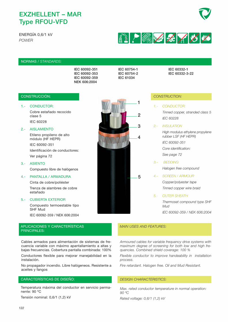
EXZHELLENT – MARType RFOU-VFD
IEC 60092-351 IEC 60754-1 IEC 60332-1IEC 60092-353 IEC 60754-2 IEC 60332-3-22IEC 60092-359 IEC 61034NEK 606:2004
1.- CONDUCTOR:
Cobre estañado recocido clase 5
IEC 60228
2.- AISLAMIENTO
Etileno propileno de alto módulo (HF HEPR)
IEC 60092-351
Identificación de conductores:
Ver página 72
3.- ASIENTO
Compuesto libre de halógenos
4.- PANTALLA / ARMADURA
Cinta de cobre/poliéster
Trenza de alambres de cobre estañado
5.- CUBIERTA EXTERIOR
Compuesto termoestable tipoSHF Mud
IEC 60092-359 / NEK 606:2004
1.- CONDUCTOR:
Tinned copper, stranded class 5
IEC 60228
2.- INSULATION
High modulus ethylene propylenerubber LSF (HF HEPR)
IEC 60092-351
Core identification:
See page 72
3.- BEDDING
Halogen free compound
4.- SCREEN / ARMOUR
Copper/polyester tape
Tinned copper wire braid
5.- OUTER SHEATH
Thermoset compound type SHFMud
IEC 60092-359 / NEK 606:2004
Armoured cables for variable frequency drive systems withmaximum degree of screening for both low and high fre-quencies. Combined shield coverage: 100 %
Flexible conductor to improve handeability in installationprocess.
Fire retardant. Halogen free. Oil and Mud Resistant.
122
ENERGÍA 0,6/1 kV
POWER
CONSTRUCCIÓN: CONSTRUCTION:
NORMAS / STANDARDS:
MAIN USES AND FEATURES:
Cables armados para alimentación de sistemas de fre-cuencia variable con máximo apantallamiento a altas ybajas frecuencias. Cobertura pantalla combinada: 100%
Conductores flexible para mejorar manejabilidad en lainstalación.
No propagador incendio. Libre halógeneos. Resistente aaceites y fangos
APLICACIONES Y CARACTERÍSTICAS PRINCIPALES:
1
CARACTERÍSTICAS DE DISEÑO: DESIGN CHARACTERISTICS:
Temperatura máxima del conductor en servicio perma-nente: 90 ºC
Tensión nominal: 0,6/1 (1,2) kV
Max. rated conductor temperature in normal operation: 90 ºC
Rated voltage: 0,6/1 (1,2) kV
2
3
4
5

EXZHELLENT – MARType RFOU-VFD
123
ENERGÍA 0,6/1 kV
POWER
CÓDIGO SECCIÓN NOMINAL
DIÁMETRO BAJOARMADURANOMINAL
DIÁMETROEXTERIORNOMINAL
PESO NOMINAL INTENSIDADADMISIBLE AIRE
45°C
CAÍDA TENSIÓN
(COS ϕ=0,8)
INDUCTANCIA
CODE NOMINAL CROSSSECTIONAL AREA
mm2
DIAMETER UNDERARMOUR NOM.
mm
NOMINAL OVE-RALL DIAMETER
mm
NOMINAL WEIGHT
kg/km
CURRENT RATINGAIR 45° C
A
VOLTAGE DROP (COS ϕ=0,8)
V/A. km
INDUCTANCE
mH/km
7490314 3x50/25 26,00 31,50 2451,00 128 0,76 0,24
7490315 3x70/35 31,50 37,00 3486,50 158 0,56 0,24
7490316 3x95/50 35,00 41,50 4506,00 191 0,44 0,23
7490317 3x120/60 39,50 48,00 5783,00 221 0,36 0,23
7490318 3x150/75 43,50 52,50 7318,00 254 0,30 0,23
7490319 3x185/95 48,00 57,00 8610,50 290 0,26 0,23
7490320 3x240/120 55,00 66,00 11221,50 341 0,22 0,23

124
Ed
ició
n:Ju
nio
2005

España/Spain: Casanova, 150 - 08036 Barcelona
www.generalcable.es
AT E N C I Ó N A L C L I E N T ET E L : 9 3 2 2 7 9 7 0 0FA X : 9 0 0 2 1 0 4 8 6C U S T O M E R S E R V I C ETEL: +34 - 93 227 97 00FAX:+34 - 93 227 97 19
ISO 9001
ISO 14001
CENTRAL / HEADQUATERS
Casanova, 150 - 08036 BARCELONATel.: 93 227 97 00 - Fax: 93 227 97 [email protected]
PORTUGALAv. Marquês de Pombal, 36-38 Morelena2715-055 PÊRO PINHEIROTel.: +351 219 678 500 - Fax: +351 219 271 [email protected]
ZONAS IBERIA / BRANCHES IBERIA
ANDALUCÍAAverroes, 6, Edificio Eurosevilla, planta 3ª, Mod. 8 y 941020 SEVILLATels.: 95 499 95 18 - 902 23 91 80 - Fax: 95 451 10 [email protected]
CENTROÁvila, Badajoz, Cáceres, Ciudad Real,Guadalajara, Madrid, Segovia y ToledoAvda. Ciudad de Barcelona, 81 A, 4º A - 28007 MADRIDTels.: 91 309 66 20 - 902 23 91 82 - Fax: 91 309 66 [email protected]
Burgos, León, Palencia, Salamanca, Valladolid y ZamoraTel. Móvil: 609 15 45 94 - Fax: 983 24 96 [email protected]
LEVANTEAlbacete, Comunidad Valenciana, Cuenca y MurciaCirilo Amorós, 27 - 6º C - 46004 VALENCIATels.: 96 350 92 58 - 902 23 91 81 - Fax: 96 352 95 [email protected]
NORDESTEAndorra, Aragón, Baleares y CataluñaCasanova, 150 - 08036 BARCELONATels.: 93 227 97 00 - 902 23 91 60 - Fax.: 93 227 97 [email protected]
NORTEÁlava, Asturias, Cantabria y VizcayaJuan de Ajuriaguerra, 26 - 48009 BILBAOTels.: 94 424 51 76 - 902 23 91 58 - Fax: 94 423 06 [email protected]
Guipúzcoa, La Rioja, Navarra, SoriaTel. 629 34 85 22 - Fax 948 23 46 [email protected]
Representación GALICIABESIGA COMERCIAL, S.L.Av. Tierno Galván, 11215178 MAIANCA - OLEIROS (La Coruña)Tel.: 981 61 71 94 - Fax: 981 61 74 [email protected]
PORTOR. Gonçalo Cristovão, 312 - 4º B e C4000-266 PORTOTel.: +351 223 392 350 - Fax: +351 223 323 878
Representación CANARIASÁngel Guerra, 23 - 1º35003 LAS PALMAS DE GRAN CANARIATel.: 928 36 11 57 - Fax: 928 36 44 73
EXPORTACIÓN / EXPORT
Casanova, 150 - 08036 Barcelona (SPAIN)Tel.: + 34 - 93 227 97 24 - Fax: + 34 - 93 227 97 [email protected]
Av. Marquês de Pombal, 36-38 Morelena2715-055 PÊRO PINHEIRO (PORTUGAL)Tel.: +351 219 678 500 - Fax: +351 219 271 942
FACTORÍAS / FACTORIES
ABRERACarrer del Metall, 4 (Polígon Can Sucarrats)08630 ABRERA (Barcelona)Tel.: 93 773 48 00 - Fax: 93 773 48 48
MANLLEUCtra. Rusiñol, 6308560 MANLLEU (Barcelona)Tel.: 93 852 02 00 - Fax: 93 852 02 22
MONTCADA I REIXACCtra. de Ribas, Km. 13,25008110 MONTCADA I REIXAC (Barcelona)Tel.: 93 227 95 00 - Fax: 93 227 95 22
MORELENAAv. Marquês de Pombal, 36-38 Morelena2715-055 PÊRO PINHEIRO (PORTUGAL)Tel.: +351 219 678 500 - Fax: +351 219 271 942
BRAZILRua Anchieta, 275 Prédio-Carapina29165-825 Bairro Carapina-SerraESPIRITU SANTO (BRASIL)Tél.: +55272281391 - Fax: +55273382588
INTERNACIONAL / INTERNATIONAL
BRAZILRua Anchieta, 275 Prédio-Carapina29165-825 Bairro Carapina-SerraESPIRITU SANTO (BRASIL)Tél.: +55272281391 - Fax: +55273382588
NORWAYRandemfaret 171540 VESTBYNORWAYTel.: (+47) 64955900 - Fax: (+47) 64955910
UNITED KINGDOM28 Railway RoadLeigh WN7 4 AU - LANCASHIRE (UNITED KINGDOM)Tel.: +44 1942 684308 - Fax: +44 1942 605000
AGENCIAS / AGENCIES
ARGENTINAFrancisco Beiró 1490Florida Este 1602BUENOS AIRES (ARGENTINA)Tel.: +54 11 4760 [email protected]
FRANCEZ.I. de la Haie Passart - 9, rue Galilée - Cedex Nº 3077257 BRIE COMTE ROBERT (FRANCE)Tel.: 01 60 62 51 40 - Fax: 01 64 05 41 [email protected]
ITALYSalvaneschi E.e.R.&C.S.A.Via Pelizza da Volpedo, 2020092 CINISELLO BALSAMOMilano (ITALY)Tel.: +39 02 660 49494 - Fax: +39 02 660 49489K


