Marinas TIRF/FRET/FRAP MicroscopeFRAP will work in epi, TIRF, FRET and Rao modes FRAP system uses a...
14
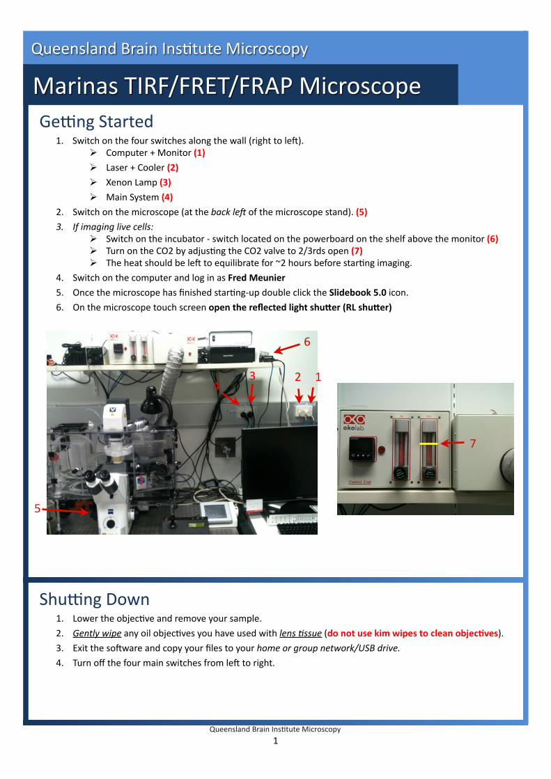
Ge#ng Started 1. Switch on the four switches along the wall (right to le8). Computer + Monitor (1) Laser + Cooler (2) Xenon Lamp (3) Main System (4) 2. Switch on the microscope (at the back le( of the microscope stand). (5) 3. If imaging live cells: Switch on the incubator ‐ switch located on the powerboard on the shelf above the monitor (6) Turn on the CO2 by adjusIng the CO2 valve to 2/3rds open (7) The heat should be le8 to equilibrate for ~2 hours before starIng imaging. 4. Switch on the computer and log in as Fred Meunier 5. Once the microscope has finished starIng‐up double click the Slidebook 5.0 icon. 6. On the microscope touch screen open the reflected light shuAer (RL shuAer) Shu#ng Down 1. Lower the objecIve and remove your sample. 2. Gently wipe any oil objecIves you have used with lens 9ssue (do not use kim wipes to clean objecHves). 3. Exit the so8ware and copy your files to your home or group network/USB drive. 4. Turn off the four main switches from le8 to right. 1 Queensland Brain InsItute Microscopy Marinas TIRF/FRET/FRAP Microscope Queensland Brain InsItute Microscopy 1 2 3 4 5 6 7
Transcript of Marinas TIRF/FRET/FRAP MicroscopeFRAP will work in epi, TIRF, FRET and Rao modes FRAP system uses a...
Ge#ng Started1. Switch on the four switches along the wall (right to le8).
Computer + Monitor (1)
Laser + Cooler (2)
Xenon Lamp (3)
Main System (4)
2. Switch on the microscope (at the back le( of the microscope stand). (5)
3. If imaging live cells: Switch on the incubator ‐ switch located on the powerboard on the shelf above the monitor (6) Turn on the CO2 by adjusIng the CO2 valve to 2/3rds open (7) The heat should be le8 to equilibrate for ~2 hours before starIng imaging.
4. Switch on the computer and log in as Fred Meunier
5. Once the microscope has finished starIng‐up double click the Slidebook 5.0 icon.
6. On the microscope touch screen open the reflected light shuAer (RL shuAer)
Shu#ng Down1. Lower the objecIve and remove your sample.
2. Gently wipe any oil objecIves you have used with lens 9ssue (do not use kim wipes to clean objecHves).
3. Exit the so8ware and copy your files to your home or group network/USB drive.
4. Turn off the four main switches from le8 to right.
1
Queensland Brain InsItute Microscopy
Marinas TIRF/FRET/FRAP Microscope
Queensland Brain InsItute Microscopy
1234
5
6
7
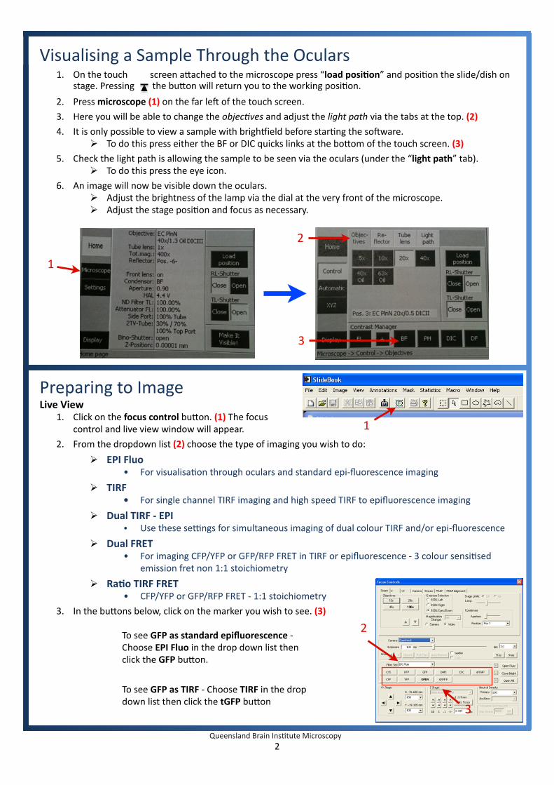
Visualising a Sample Through the Oculars1. On the touch screen a`ached to the microscope press “load posiHon” and posiIon the slide/dish on
stage. Pressing the bu`on will return you to the working posiIon.
2. Press microscope (1) on the far le8 of the touch screen.
3. Here you will be able to change the objec9ves and adjust the light path via the tabs at the top. (2)
4. It is only possible to view a sample with brighdield before starIng the so8ware. To do this press either the BF or DIC quicks links at the bo`om of the touch screen. (3)
5. Check the light path is allowing the sample to be seen via the oculars (under the “light path” tab). To do this press the eye icon.
6. An image will now be visible down the oculars. Adjust the brightness of the lamp via the dial at the very front of the microscope. Adjust the stage posiIon and focus as necessary.
Preparing to ImageLive View
1. Click on the focus control bu`on. (1) The focus control and live view window will appear.
2. From the dropdown list (2) choose the type of imaging you wish to do:
EPI Fluo • For visualisaIon through oculars and standard epi‐fluorescence imaging
TIRF • For single channel TIRF imaging and high speed TIRF to epifluorescence imaging
Dual TIRF ‐ EPI • Use these se#ngs for simultaneous imaging of dual colour TIRF and/or epi‐fluorescence
Dual FRET• For imaging CFP/YFP or GFP/RFP FRET in TIRF or epifluorescence ‐ 3 colour sensiIsed
emission fret non 1:1 stoichiometry
RaHo TIRF FRET• CFP/YFP or GFP/RFP FRET ‐ 1:1 stoichiometry
3. In the bu`ons below, click on the marker you wish to see. (3)
2Queensland Brain InsItute Microscopy
1
2
3
2
3
1
To see GFP as standard epifluorescence ‐ Choose EPI Fluo in the drop down list then click the GFP bu`on.
To see GFP as TIRF ‐ Choose TIRF in the drop down list then click the tGFP bu`on
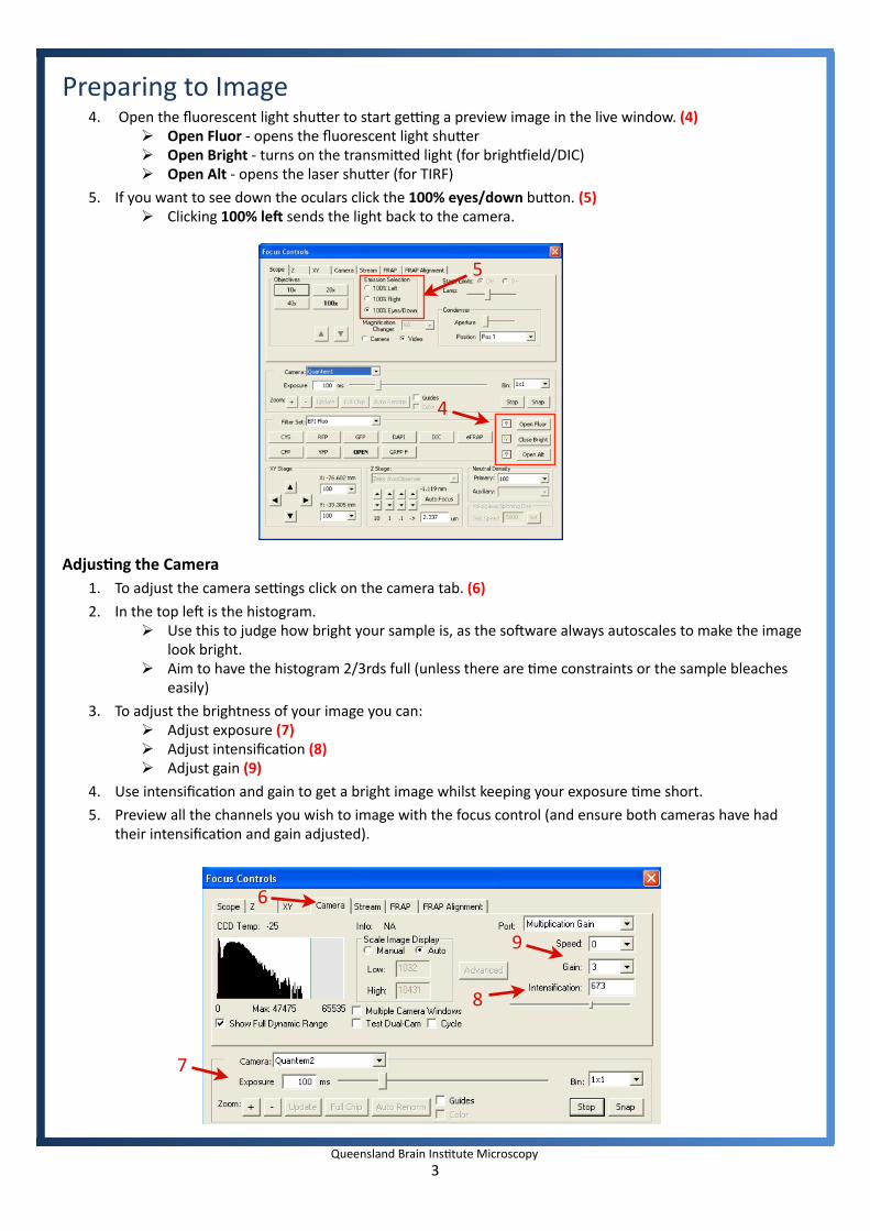
Preparing to Image4. Open the fluorescent light shu`er to start ge#ng a preview image in the live window. (4)
Open Fluor ‐ opens the fluorescent light shu`er Open Bright ‐ turns on the transmi`ed light (for brighdield/DIC) Open Alt ‐ opens the laser shu`er (for TIRF)
5. If you want to see down the oculars click the 100% eyes/down bu`on. (5) Clicking 100% leZ sends the light back to the camera.
AdjusHng the Camera1. To adjust the camera se#ngs click on the camera tab. (6)
2. In the top le8 is the histogram. Use this to judge how bright your sample is, as the so8ware always autoscales to make the image
look bright. Aim to have the histogram 2/3rds full (unless there are Ime constraints or the sample bleaches
easily)
3. To adjust the brightness of your image you can: Adjust exposure (7) Adjust intensificaIon (8) Adjust gain (9)
4. Use intensificaIon and gain to get a bright image whilst keeping your exposure Ime short.
5. Preview all the channels you wish to image with the focus control (and ensure both cameras have had their intensificaIon and gain adjusted).
3Queensland Brain InsItute Microscopy
4
5
9
7
8
6

Capturing an Image1. Click the capture image icon. (1) The focus control
and live view window will appear.
2. In the drop down list choose the imaging type. (2)
3. Tick the box next to each channel you wish to capture. (3)
4. Check the exposure Ime of each channel. Do this by highlighIng the channel by clicking on it, then pressing test. (4) Adjust the exposure Ime as necessary to get a good range of intensiIes in the histogram box. (5) Each Ime you press test it will take only one image ‐ prevents bleaching
5. Check the exposure on each channel you wish to image then click Start (6) to take an image.
Timelapse Imaging1. Enable Imelapse. (7)
2. Enter # of Imepoints (8) and interval. (9)
3. Click Start to capture movie.
4Queensland Brain InsItute Microscopy
1
2
3 4
5
6
7
9
8

Capturing an ImageTIRF Imaging TIRF uses an angled laser to illuminate the bo`om 100nm of a cell and can only be achieved using the 100x objecHve.
When the angle or focus of the laser is not set correctly it will not be possible to get a TIRF image.
If you have trouble ge#ng an image ‐ do not aAempt to adjust the laser yourself. Instead, call Luke on 0402 586 647.
Dual TIRF / EpiThese se#ngs are used to get an image of the TIRF layer and the epifluorescent layer in the same focal plane. This technique is used to determine whether carriers are fusing to the plasma membrane or moving upwards into the cell.
Choose Dual TIRF / Epi in the dropdown menu and then select the appropriate channels
‐ For example in the case of GFP choose dtGFP and deGFP
Simultaneous ImagingThe Marinas microscope has two cameras so that two channels can be captured simultaneously.
To image simultaneously use the Dual TIRF / Epi se#ngs.
It is important to ensure that the two channels that are captured simultaneously (e.g. dtGFP + dtRFP) have the same the same exposure Ime.
High‐speed Timelapse / StreamingUsing Imelapse in the capture window the maximum speed is limited to 20 Hz (full frame/chip). If you need to go faster than this you will need to use Streaming in the focus control window.
Using Streaming you will be able to image at 30Hz full frame, 60Hz at 256x256, 105Hz at 128x128
To use streaming:
1. Set‐up channel in focus control (exposure, intensificaIon, gain).
2. Click on the Stream tab. (1)
3. Enable Start recording when start buAon clicked. (2)
4. Open the Fl or Alt shu`er to illuminate sample.
5. Click start. (3)
5Queensland Brain InsItute Microscopy
In the capture type, enable simultaneous imaging.
1
2
3
FRET Imaging (Forster/Fluorescence Resonance Energy Transfer)Fimage = Freal + Donor bleed‐through + Cross excitaIon
therefore
Freal = Fimage ‐ Donor bleed‐through ‐ Cross excitaIon
Capture 1. Donor only sample ‐ Donor excitaIon and Donor emission 2. Acceptor only sample ‐ Donor excitaIon and Acceptor emission 3. Donor + Acceptor Emission
1. Donor ONLY sample: Donor ExcitaHon‐ Look at donor emission ‐ Look at acceptor emission
‐ Image several fields figure out bleed‐through for each and get mean‐ Use same se#ngs (e.g. 100ms exposure, same ND filter etc)
‐ Create segment mask based on donor (mask bu`on above captured image)‐ FRET > compute FRET bleed‐through
‐ Have background ROI (draw ROI, select, set as background)‐ Set up FRET pairs (e.g. GFP, RFP, RFP as Transfer)‐ Factor 0.64 means 64% of image is bleed‐through‐Make default
2. Acceptor ONLY sample: Donor ExcitaHon‐ Segment mask on acceptor (look at donor)‐ Draw ROI ‐ background‐ FRET
3. Donor + Acceptor Emission FRET sefngs Image sample
4. FRET sefngs Click use default (imports values from steps 1 and 2) Different opIons for calculaIng FRET
1st is basic calculaIon 2nd and 3rd raIometric for visualisaIon BUT raIo of molecules has to be 1:1 4th has correcIon factor “g” to allow for different raIos of donor/acceptor 6th Efret also calculates for photobleaching
5. Run calculaHon and create virtual FRET channel Segment out cells
Menu staIsIcs > mask staIsIcs Run staIsIcs to normalise for different brightnesses in donor
Notes:Make sure your background ROI is in a clear spot ‐‐> view image with high contrast (manual scale low) ALWAYS use the same method ‐ don’t change algorithm Donor and acceptor alone can have different exposure Imes
But for actual experiment exposure Imes for all needs to be the same Calibrate on brightest channel ‐ usually GFP
in 1:1 cross excitaIon irrelevant only opIon is to FRET or not FRET (only excite with donor excitaIon)
RaIo ‐ FRET > add donor and transferAcceptor photobleaching FRET Image donor > bleach acceptor > image donor again Donor brightness should increaseQuanItaIve technique (other FRET techniques are QUALITATIVE ‐ Yes/No ‐ won’t tell you how much FRET is occurring)
6Queensland Brain InsItute Microscopy

Imaging a Sample: FRETDual FRETFor high speed FRET experiments for 3 channel FRET capturing Donor, FRET, Acceptor.
Each subset of filters must be captured using the same exposure Ime ‐ requires simultaneous imaging.
Filters: GFP/RFP = dGFP + dGRFP + dDUM2 + dRFP
CFP/YFP = dCFP + dCYFP + dDUM + dYFP
RaHo FRET For high speed FRET experiments for 2 channel FRET capturing Donor, FRET, Acceptor.
Only when you have bound Donor and Acceptor in a 1:1 stochiometry.
Data will be automaIcally displayed in pseudocolour as FRET/Donor
Filters: rtGFP + rtGRFP or rtCFP + rtCYFP or erCFP + erCYFP
7Queensland Brain InsItute Microscopy

FRAP ‐ Performing FRAP experiments and analysisFRAP will work in epi, TIRF, FRET and RaIo modes
FRAP system uses a 337nm laser to excite cumarin dye ‐ which then emits a 440nm beam able to bleach GFP.
You must have an emission filter in place when performing FRAP. This will prevent damage to the CCD.
Sefng up a FRAP experiment1. Insert the correct Mirror at the back of the microscope ‐ 50/50 Mirror
2. Switch on the FRAP module via the key.
3. Ensure FRAP laser has been aligned and calibrated.
4. Set up your normal imaging preferences in the focus window
5. In the Image Capture window click on Advanced... (1) and go to the FRAP tab
6. Select the filter you will be using from the ablaHon filter drop down menu (e.g. tGFP or dtGFP) (2)
7. Adjust the radius of the double‐click FRAP size (1 = 1 pixel / default) or edit the se#ngs for a FRAP ROI (draw an ROI on the live image via the region select tools in the top toolbar)
ROI FRAP and Monitoring Intensity1. Set up your imaging preferences. Click Test in the Capture window and draw the ROI for FRAP
2. Choose your ablaIon filter (as above) and number iteraIons required
3. In the FRAP tab under Automated control add in the ROI you have drawn.
4. You may also draw a background ROI, by drawing a ROI in an empty space (right click on ROI and select “make background”)
5. While capturing click Show (in the lower right corner of the capture controls, e.g. Show: dtGFP)
8Queensland Brain InsItute Microscopy
1
2

FRAP ‐ CalibraIon and AlignmentAlignment of the FRAP laser
1. Insert the correct Mirror at the back of the microscope ‐ 50/50 Mirror
2. Switch on the FRAP module via the key.
3. Choose the objecIve you wish to use and open the Focus Window
4. Place the mirror slide on the stage (mirrored surface face down)
5. Use the dual TIRF GFP/RFP filter cube
6. Direct the light‐path to the camera (do not look down eyepieces)
7. Under the FRAP tab in the Focus window set the FRAP laser power to 30‐60% (1)
8. Centre the laser by entering “128” into both the X and Y Axis (2) and clicking Go.9. Turn on the FRAP laser and turn the repeIIon rate knob unIl it is at 3‐5 Hz (you will hear a click every
Ime the laser fires). A hole should appear when the laser has repeatedly struck the mirror If a hole does not appear ‐ call Luke (0402 586 647)
• Pivot the glavo heads with repeIIon rate at 0 ‐ do not loosen hex screws that hold galvos• Locate the OFF switch for the galvos ‐ galvos must be turned off immediately if they make
any noise during pivoIng.
10. Turn the repeIIon rate knob back to 0 Hz (external pulse mode) and move to a new posi9on on the slide then press Pulse Laser (3)
11. If a hole appears ‐ reduce the laser and repeat step 8 ‐ keep going unIl one pulse does not produce a hole.
12. Now repeat step 8 but instead of adjusIng the power, adjust the focus of the laser (telescoping lens)
The aim is to get the maximum laser power at the plane of focus
9Queensland Brain InsItute Microscopy
1
2
3
FRAP ‐ CalibraIon and AlignmentAlignment of Camera with FRAP unit
1. Ensure the Camera view is aligned square with the FRAP module ‐ if you have used the grid slide to ensure both cameras are aligned (see camera alignment) this will already be the case. If not, put the grid slide on and make sure the pa`ern is square.
2. At the bo`om of the laser tab of the focus window, select either X or Y axis and enter “25” to “225” step: “20” then Fire Test PaAern (on to Mirror Slide)
3. Observe the alignment of the line of holes in the image field. Rotate the FRAP unit slightly and repeat step 2. unIl the FRAP unit is aligned with the stage.
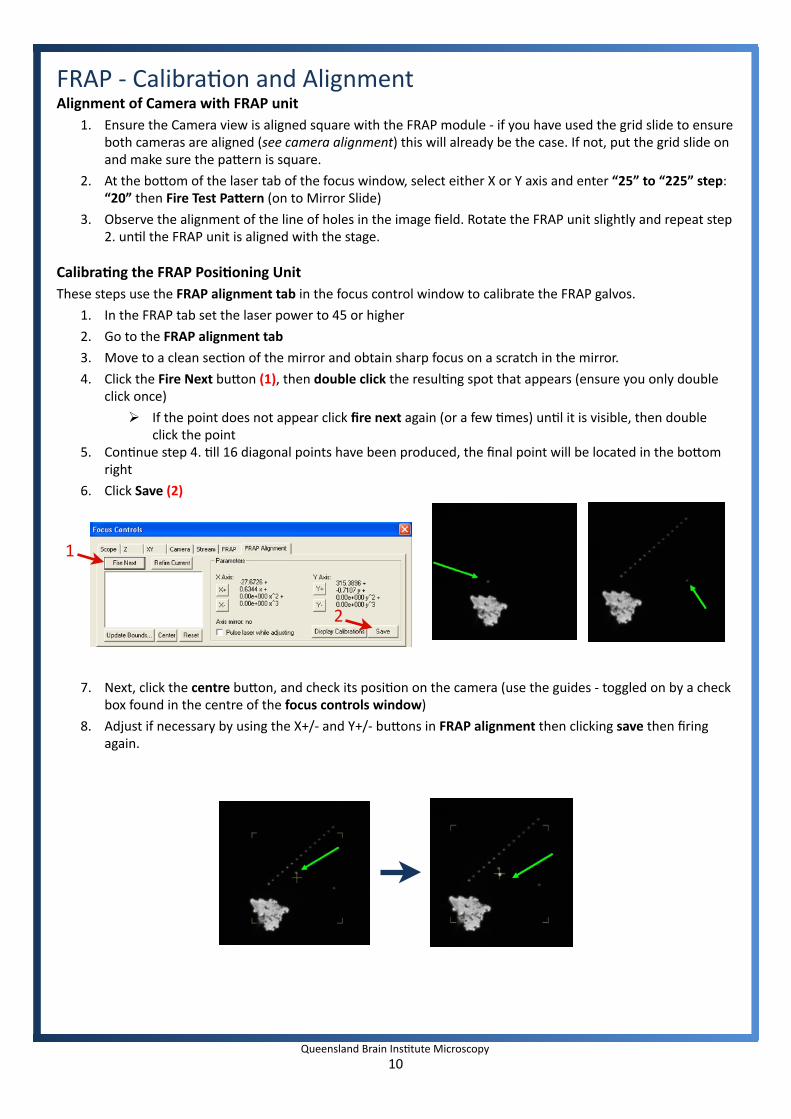
CalibraHng the FRAP PosiHoning UnitThese steps use the FRAP alignment tab in the focus control window to calibrate the FRAP galvos.
1. In the FRAP tab set the laser power to 45 or higher
2. Go to the FRAP alignment tab
3. Move to a clean secIon of the mirror and obtain sharp focus on a scratch in the mirror.
4. Click the Fire Next bu`on (1), then double click the resulIng spot that appears (ensure you only double click once)
If the point does not appear click fire next again (or a few Imes) unIl it is visible, then double click the point
5. ConInue step 4. Ill 16 diagonal points have been produced, the final point will be located in the bo`om right
6. Click Save (2)
7. Next, click the centre bu`on, and check its posiIon on the camera (use the guides ‐ toggled on by a check box found in the centre of the focus controls window)
8. Adjust if necessary by using the X+/‐ and Y+/‐ bu`ons in FRAP alignment then clicking save then firing again.
10Queensland Brain InsItute Microscopy
1
2
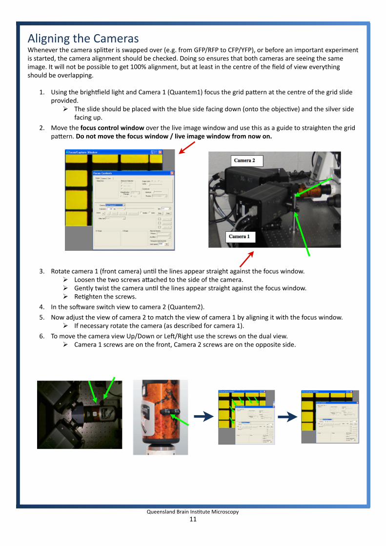
Aligning the CamerasWhenever the camera spli`er is swapped over (e.g. from GFP/RFP to CFP/YFP), or before an important experiment is started, the camera alignment should be checked. Doing so ensures that both cameras are seeing the same image. It will not be possible to get 100% alignment, but at least in the centre of the field of view everything should be overlapping.
1. Using the brighdield light and Camera 1 (Quantem1) focus the grid pa`ern at the centre of the grid slide provided.
The slide should be placed with the blue side facing down (onto the objecIve) and the silver side facing up.
2. Move the focus control window over the live image window and use this as a guide to straighten the grid pa`ern. Do not move the focus window / live image window from now on.
3. Rotate camera 1 (front camera) unIl the lines appear straight against the focus window. Loosen the two screws a`ached to the side of the camera. Gently twist the camera unIl the lines appear straight against the focus window. ReIghten the screws.
4. In the so8ware switch view to camera 2 (Quantem2).
5. Now adjust the view of camera 2 to match the view of camera 1 by aligning it with the focus window. If necessary rotate the camera (as described for camera 1).
6. To move the camera view Up/Down or Le8/Right use the screws on the dual view. Camera 1 screws are on the front, Camera 2 screws are on the opposite side.
11Queensland Brain InsItute Microscopy
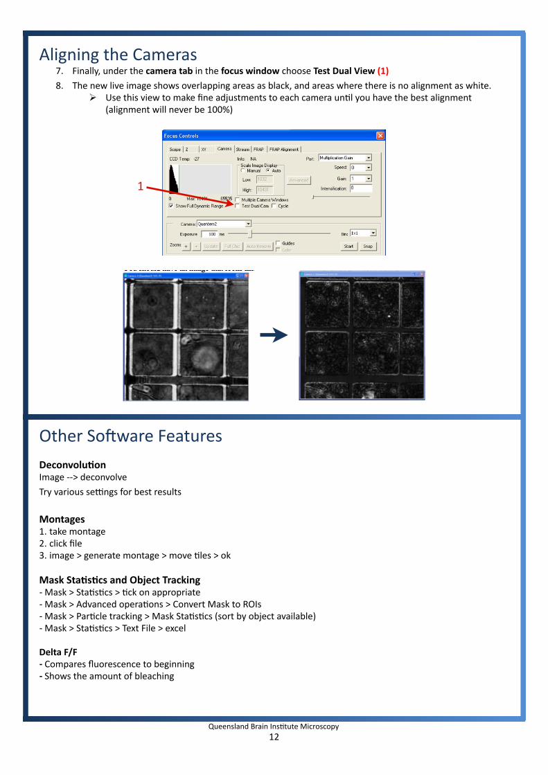
Aligning the Cameras7. Finally, under the camera tab in the focus window choose Test Dual View (1)
8. The new live image shows overlapping areas as black, and areas where there is no alignment as white. Use this view to make fine adjustments to each camera unIl you have the best alignment
(alignment will never be 100%)
Other So8ware Features
DeconvoluHonImage ‐‐> deconvolve
Try various se#ngs for best results
Montages1. take montage2. click file3. image > generate montage > move Iles > ok
Mask StaHsHcs and Object Tracking ‐Mask > StaIsIcs > Ick on appropriate‐Mask > Advanced operaIons > Convert Mask to ROIs‐Mask > ParIcle tracking > Mask StaIsIcs (sort by object available)‐Mask > StaIsIcs > Text File > excel
Delta F/F Compares fluorescence to beginning Shows the amount of bleaching
12Queensland Brain InsItute Microscopy
1

Other So8ware Features
FRAP Analysis StaHsHcs‐ > FRAP analysis‐ get baseline Ime points‐ asymptote Ime points (where fla`ened out)‐ photobleach to ROI (make ROI on unbleached region)‐ gives half life and mobile fracIon
CompuHng Channel RegistraHon‐ Use beads‐ Chan 1 > Mask‐ Chan2 > Mask‐ Image > Advanced operaIons > Compute Channel registraIon
ExportImage ‐‐> Export ‐‐> channel intensiIes as 16bit If file
13Queensland Brain InsItute Microscopy

Ergonomics: Use of mouse and keyboard / viewing computer screen – Prolonged use of the microscope and microscope computer without breaks can increase the risk of muscular strain.
Eye strain and fatigue – Viewing samples through microscope eye piece or computer monitor over lengthy periods of time can result in eyestrain and headaches. Exposure to sharps – Exposure to razor blades, scalpels, forceps, cover slips, glass slides could result in cuts or puncture wounds to hands or other areas of the body. Any microscope slide shards or glass debris must be disposed of in the appropriate shapes disposable bin in accordance with PC2 regulations.
Exposure to intense fluorescent and laser light – Lasers and a xenon light source are attached to this microscope and are the source of intense and potentially dangerous light. Under no circumstances should any optical elements be removed from the microscope light path or fail-safe switches be circumvented. Do not attempt to adjust the lasers, laser light path, or laser modules in any way. Avoid direct exposure to the light.
Scope This procedure details the method for using the microscopes equipped with laser light sources.
Safety Considerations
Personal Protective Equipment (PPE): Laboratory coat, latex gloves and closed in shoes should be worn to prevent injury.
Ergonomics and Risk Exposure: Appropriate ergonomics, including adjustment of the seat, computer screen and microscope oculars should be undertaken to reduce risk of strain injuries.
Emergency Procedures: First aid may be required for: Exposure to sharps – Contact the nearest first aid officer from the list that is beside all first aid kits and on safety notice board.
Exposure to intense fluorescent and laser light – Seek immediate medical assistance if you have been exposed to intense direct light or laser light.
In the event of a laser accident, do the following: 1. Shut down the laser system. 2. Provide for the safety of personnel (first aid, evacuation, etc). If needed, provide further medical
assistance for Eye Injuries by: Proceed directly to: Royal Brisbane and Women’s Hospital at Cnr Butterfield St and Bowen Bridge Rd HERSTON, QUEENSLAND AUSTRALIA 4029
(07) 3636 8222
Note: If a laser eye injury is suspected, have the injured person keep still and looking straight up to restrict bleeding in the eye. Laser eye injuries should be evaluated by a physician as soon as possible.
3. Contact UQ Security Emergency on 336 5333. 4. Inform QBI’s Laser Safety Officer, Rumelo Amor on 04 4907 8485, of the accident as soon as
possible. 5. A UQ online incident report must be completed as soon as possible after the incident.
All incidents must be reported to the OH&S Manager and on UQs online incident reporting system.
Contacts: Security x53333 or OH&S Manager Ross Dixon 0401 673 654
QUEENSLAND BRAIN INSTITUTE – STANDARD OPERATING PROCEDURE
WORKING WITH CONFOCAL AND TIRF MICROSCOPES