MarconiOMS3240 ProductDescription
75
Ericssonwide Internal TECHN PRODUCT DESCR Prepared (also subject responsible if other) No. ETL/G/S Henry Gonzalez 221 02-ZAP 164 01/4 Approved Checked Date Rev Reference ETL/G/S Karl-Eric K Malberg 05/08/2005 A OMS 3240 Product Description Marconi is the original manufacturer of this product. Ericsson and Marconi have had a close relationship since 1995. The Ericsson Optical Network is a transport network portfolio provided in conjunction with Marconi. It includes SDH and DWDM NE’s and a common NMS system. The portfolio is broad and complete.
-
Upload
joshua-johnson -
Category
Documents
-
view
73 -
download
0
description
MArcponi
Transcript of MarconiOMS3240 ProductDescription
Ericssonwide Internal TECHN PRODUCT DESCR
Prepared (also subject responsible if other) No.
ETL/G/S Henry Gonzalez 221 02-ZAP 164 01/4 Approved Checked Date Rev Reference
ETL/G/S Karl-Eric K Malberg 05/08/2005 A
OMS 3240
Product Description
Marconi is the original manufacturer of this product. Ericsson and Marconi have had a close relationship since 1995. The Ericsson Optical Network is a transport network portfolio provided in conjunction with Marconi. It includes SDH and DWDM NE’s and a common NMS system. The portfolio is broad and complete.
OMS3240SDH/OTH 10GB/S COMPACTADD DROP MULTIPLEXER
Product Description
Issue 1
Product Description OMS3240
Page 2 of 74 Copyright – Refer to Page 2 Issue 1
Document code:Date of issue:Issue:Comments:
4on-pd000074-e6 July 20041
Marconi Communications Ltd. and the Marconi logo are trademarks of Marconi.
This is an unpublished work, the copyright in which vests in Marconi Communications Limited, Marconi Communications SpA andMarconi Communications GmbH. All rights reserved. The work contains information confidential to the above companies and allsuch information is supplied without liability for errors or omissions. No part may be reproduced, disclosed or used except asauthorized by contract or other written permission. The copyright and the foregoing restriction on reproduction extend to all media inwhich the information may be embodied.
The above companies have used all reasonable endeavors to ensure that the information contained in this work is accurate at itsdate of issue, but reserves the right to make changes, in good faith, to such information from time to time, whether by way ofcorrection or meet market requirements or otherwise.
Marconi Communications Ltd.,New Century Park,PO Box 53, Coventry CV3 1HJ,EnglandTelephone: +44 (0)24 7656 2000Fax: +44 (0)24 7656 7000Telex: 31361 MARCOV
Marconi Communications GmbHGerberstraße 3371522 BacknangGermanyTelephone: +49 (0) 71 91 13 - 0Fax: +49 (0) 71 91 13 - 32 12
Marconi Communications SpA,1A, via Negrone 16153,Genova, Cornigliano,Italy.Telephone: +39–010–60021Fax: +39–010–6501897
OMS3240 Product Description
Issue 1 Copyright – Refer to Page 2 Page 3 of 74
TABLE OF CONTENTS
List of Abbreviations .............................................................................................................. 71 INTRODUCTION................................................................................................... 101.1 SDH Hierarchy....................................................................................................... 111.2 OTN Hierarchy....................................................................................................... 122 CONFIGURATION ................................................................................................ 133 LINE INTERFACES............................................................................................... 164 TRIBUTARY INTERFACES................................................................................... 174.1 Interfaces and protection........................................................................................ 174.2 Synchronisation Interfaces..................................................................................... 194.3 Electrical Interfaces Characteristics ....................................................................... 194.4 Optical Interfaces Characteristics........................................................................... 194.4.1 SDH Multirate card................................................................................................. 224.4.2 Gigabit Ethernet card ............................................................................................. 234.4.3 Multi-Protocol Data card......................................................................................... 244.4.4 Aggregation Data card ........................................................................................... 254.4.4.1 L2 transport ....................................................................................................... 254.4.4.2 L2 switching:...................................................................................................... 264.4.5 OTM cards ............................................................................................................. 275 MAPPING & MULTIPLEXING FUNCTIONS.......................................................... 306 SECTION AND PATH OVERHEAD BYTES PROCESSING.................................. 316.1 SOH Bytes Description .......................................................................................... 316.1.1 Regeneration Section Overhead (RSOH)............................................................... 316.1.2 Multiplex Section Overhead (MSOH) ..................................................................... 326.2 POH Bytes Description .......................................................................................... 326.2.1 VC-4 / VC-4Xc / VC-4-Xv POH .............................................................................. 326.2.2 Connection Supervision Functions......................................................................... 336.2.3 Tandem Connection Monitoring ............................................................................. 337 OTN OVERHEAD BYTE PROCESSING ............................................................... 348 CONNECTION SUBSYSTEM................................................................................ 358.1 LO-VC Switching.................................................................................................... 369 USAGE OF OMS3240 AS OMS3260 PORT SHELF ............................................. 4010 NETWORK APPLICATIONS AND PROTECTIONS .............................................. 4110.1 MSP protection ...................................................................................................... 4110.2 MS-SPRing Protection ........................................................................................... 4110.3 Ring Interworking Protection .................................................................................. 4310.4 OTN protection....................................................................................................... 4310.5 Sub-network connection protection ........................................................................ 4410.6 OS Restoration ...................................................................................................... 4510.7 Fast Restoration..................................................................................................... 4511 AUTOMATIC SWITCHING TRANSPORT NETWORK with OMS3240 .................. 4612 EQUIPMENT ARCHITECTURE ............................................................................ 4712.1 Block Diagram ....................................................................................................... 4712.1.1 Line Units............................................................................................................... 4812.1.2 Tributary Units ....................................................................................................... 4812.1.3 OTN Tributary/Line Units ....................................................................................... 4912.1.4 HO Switch Unit....................................................................................................... 49

Product Description OMS3240
Page 4 of 74 Copyright – Refer to Page 2 Issue 1
12.1.5 LO-VC Switch Unit..................................................................................................5012.1.6 Communication/Controller Unit ...............................................................................5012.1.7 Auxiliary Unit ..........................................................................................................5012.2 Internal Distribution Of Signals ...............................................................................5012.2.1 Traffic signals .........................................................................................................5112.2.2 Timing signals ........................................................................................................5212.2.3 Synchronisation Status Messaging.........................................................................5212.2.4 Control signals........................................................................................................5212.2.5 Overhead................................................................................................................5312.2.6 Power supply..........................................................................................................5412.3 Card Slot Allocation ................................................................................................5512.4 Mechanical Structure..............................................................................................5612.5 Connectors .............................................................................................................5812.5.1 Optical Traffic Connectors ......................................................................................5812.5.2 Electrical Traffic Connectors...................................................................................5812.5.3 Other Connectors ...................................................................................................5812.6 Cables ....................................................................................................................5913 ALARMS ................................................................................................................6013.1 Unit Alarm Displays ................................................................................................6013.2 Rack Alarm Displays...............................................................................................6013.3 Alarm Processing ...................................................................................................6114 PERFORMANCE MONITORING AND MANAGEMENT.........................................6314.1 OTN performance monitoring .................................................................................6315 SERVICES.............................................................................................................6515.1 Engineering Order Wire (EOW) ..............................................................................6515.2 Data channels ........................................................................................................6516 GENERAL OPERATING FEATURES ....................................................................6716.1 Equipment Use.......................................................................................................6716.2 Plug-in Unit Handling..............................................................................................6716.3 Fault Management (Self Diagnostic).......................................................................6716.4 Recovery From Faults ............................................................................................6816.5 Equipment Robustness...........................................................................................6816.6 Inventory.................................................................................................................6817 EQUIPMENT MANAGEMENT ...............................................................................6918 TECHNICAL SPECIFICATIONS ............................................................................7118.1 Electrical Environment ............................................................................................7118.2 Climatic and Mechanical Environment ....................................................................7118.2.1 General ..................................................................................................................7118.2.2 Storage Endurance.................................................................................................7118.2.3 Transport Endurance..............................................................................................7118.2.4 Environmental Endurance For Indoor Operation.....................................................7118.3 System Performance ..............................................................................................7218.3.1 Error Performance ..................................................................................................7218.3.2 Transmission Delay ................................................................................................7218.3.3 Jitter Characteristics ...............................................................................................7218.4 Power Requirements (according to ETSI ETS 300-132) .........................................7218.5 Synchronisation ......................................................................................................7218.6 Power Consumption ...............................................................................................7318.7 Safety .....................................................................................................................7318.7.1 General ..................................................................................................................7318.7.2 Optical safety requirements ....................................................................................74
OMS3240 Product Description
Issue 1 Copyright – Refer to Page 2 Page 5 of 74
List of Figures
Figure 1: HO SDH Hierarchy ....................................................................................................11
Figure 2: SDH Hierarchy...........................................................................................................12
Figure 3: OTN (Optical Transport Network) structure according to ITU-T G.709 .......................12
Figure 4: OMS3240 Subrack layout ..........................................................................................13
Figure 5: Regenerator Subrack layout ......................................................................................14
Figure 6: Amplifier Extension Subrack layout............................................................................15
Figure 7: features provided by the OTM-0.2/1r.2 card...............................................................27
Figure 8: OMS3240 Transmission of payload to switch via backplane......................................35
Figure 9: Evolution to the integrated LO switching ....................................................................36
Figure 10: LO-VC Switch cards redundancy .............................................................................38
Figure 11: Processing inside the LO Stitching matrix ................................................................39
Figure 12: Two fibre MS-SPRing (Normal Condition)................................................................42
Figure 13:Two fibre MS-SPRing (Unidirectional Link Failure) ...................................................42
Figure 14:Two fibre MS-SPRing (Node Failure)........................................................................43
Figure 15: OMS3240 General Block Diagram...........................................................................47
Figure 16: Distribution of Traffic Signals using 622Mb/s (or 2.5Gb/s) LVDS links .....................51
Figure 17: OMS3240 Distribution of Timing Signals..................................................................52
Figure 18: Distribution of Control Signals..................................................................................53
Figure 19: Distribution of OH Bytes...........................................................................................54
Figure 20: Power Supply Distribution........................................................................................55
Figure 21: OMS3240 Card slot allocation .................................................................................56
Figure 22: Example of the use of EOW Extension interfaces ....................................................65
Product Description OMS3240
Page 6 of 74 Copyright – Refer to Page 2 Issue 1
List of Tables
Table 1: Line interfaces characteristics .................................................................................... 16
Table 2: Max number of SDH, Ethernet, SAN and Digital Video tributary interface access(assuming two STM-64 line units equipped)...................................................................... 17
Table 3: Max number of SDH/ODU tributary interface access (two extra line units available)... 18
Table 4: OMS3240 Tributary Add/Drop port Capacity assuming all Line slots are equipped..... 18
Table 5: Port capacities for each variant of Multirate card ........................................................ 23

OMS3240 Product Description
Issue 1 Copyright – Refer to Page 2 Page 7 of 74
List of AbbreviationsADM Add-Drop MultiplexerALS Automatic Laser ShutdownAPS Automatic Protection SwitchingATM Asynchronous Transfer ModeAUX Auxiliary (Unit, Channels, Services)Bw7R Bauweise 7R (local alarm scheme)c Contiguously concatenated signal (VC4-4c)CIR Committed Information RateCMISE Common Management Information Service Element (provides services
detailed in ISO9595, ISO9596 required by the NE application - OSI layer 7)CMOX CMISE over short stackDCC Data Communication ChannelDCF Dispersion Compensation Fibre (also known as PDC)DCS Digital Cross–connect SystemDWDM Dense Wavelength Division MultiplexingDXC Digital Cross–ConnectEIR Excess Information Rate EIR = PIR - CIREOW Engineer Order WireEPL Ethernet Private LineETSI European Telecommunication Standards InstituteFastE Fast EthernetFEC Forward Error Correction10GE 10 Gigabit EthernetGbE Gigabit EthernetGE Gigabit EthernetGFP Generic Frame ProcedureGigE Gigabit EthernetGMPLS Generalised Multi Protocol Label/Lambda SwitchingHO High Order, means n x VC-4HPC Higher order Path ConnectionIB FEC In Band Forward Error CorrectionIEEE Institution of Electrical and Electronic EngineersI/F InterfaceIP Internet ProtocolITU-T International Telecommunication Union, Telecommunications SectorLAN Local Area NetworkLAPS Link Access Procedure SDHLCAS Link Capacity Adjustment Scheme (for Virtual Concatenated signals)LCT Local Craft TerminalLO Low Order, means n x VC-12 level or n x VC-3LTU Line Termination UnitLVDS Low Voltage Differential SignallingMNR Managed Network ReleaseMPLS Multi-Protocol Label SwitchingMS Multiplex SectionMSH Product name for Marconi SDH multiplexersMSP Multiplex Section ProtectionMS SPRING Multiplex Section Shared Protection RingMV36 Marconi Communications Element Level Management SystemMV38 Marconi Communications Network Level Management SystemNE Network ElementNMS Network Management System
Product Description OMS3240
Page 8 of 74 Copyright – Refer to Page 2 Issue 1
OCH Optical Channel (ITU–T G.709)ODU Optical Data unit (ITU–T G.709)OH OverheadOOB FEC Out Of Band Forward Error CorrectionOPU Optical Payload Unit (ITU–T G.709)OSI Open System InterconnectionOTH Optical Transport HeirarchyOTU Optical Transport Unit (ITU–T G.709)PDC Passive Dispersion Compensation (also known as DCF)PIR Peak Information RateRS Regenerator SectionRMON Remote Network MonitoringSAN Storage Area NetworkSDH Synchronous Digital HierarchySFP Small Form-Factor Pluggable (Optical Transceiver)SMC System Memory Card, used in CCU to hold SW for all of the cards (compact
flash disks)SNC Subnetwork Connection (previously known as Path Protection)SNCP Sub-Network Connection ProtectionSOH Section OverheadSONET Synchronous Optical NetworkSTM Synchronous Transport ModuleTE Termination pointTEP1E Transmission Equipment Practice 1E (customised local alarm scheme)TM Terminal MultiplexerTMN Telecommunication Management NetworkU Unit of measure for card slot width on the subrack, 1U = 5.08mm (0.2”)UPSR Unidirectional Path Switched Ringv Virtually concatenated signal (VC4-4v)VC Virtual ContainerVCG Virtually Concatenated GroupVCI Virtual Channel IdentifierVLAN Virtual Local Area Network (IEEE 802.1Q)VPLS Virtual Private LAN ServiceVPN Virtual Private NetworkWAN Wide Area NetworkWDM Wavelength Division MultiplexingXFP Extended Form-Factor Pluggable (Optical Transceiver)

OMS3240 Product Description
Issue 1 Copyright – Refer to Page 2 Page 9 of 74
Foreword
The product information contained herein is independent of product release and does not referto a defined product release.
The technical information provided in this document is offered, in good faith, as an indication ofMarconi's intention to evolve its Optical Networks portfolio to meet the demands of themarketplace. Unless commercially agreed, the information contained herein should not to betaken as implying any commitment or obligation on the part of Marconi.
For details concerning availability and supported features please refer to the SDH Roadmap.
Product Description OMS3240
Page 10 of 74 Copyright – Refer to Page 2 Issue 1
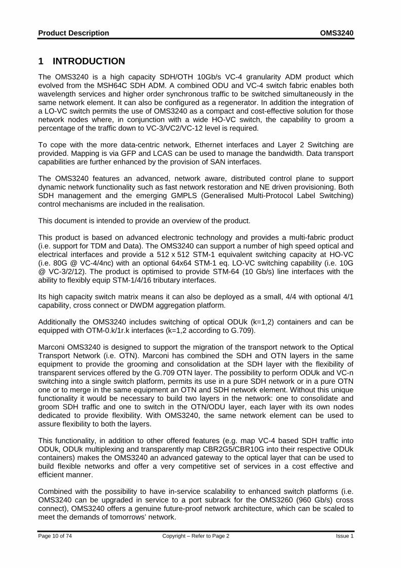
1 INTRODUCTIONThe OMS3240 is a high capacity SDH/OTH 10Gb/s VC-4 granularity ADM product whichevolved from the MSH64C SDH ADM. A combined ODU and VC-4 switch fabric enables bothwavelength services and higher order synchronous traffic to be switched simultaneously in thesame network element. It can also be configured as a regenerator. In addition the integration ofa LO-VC switch permits the use of OMS3240 as a compact and cost-effective solution for thosenetwork nodes where, in conjunction with a wide HO-VC switch, the capability to groom apercentage of the traffic down to VC-3/VC2/VC-12 level is required.
To cope with the more data-centric network, Ethernet interfaces and Layer 2 Switching areprovided. Mapping is via GFP and LCAS can be used to manage the bandwidth. Data transportcapabilities are further enhanced by the provision of SAN interfaces.
The OMS3240 features an advanced, network aware, distributed control plane to supportdynamic network functionality such as fast network restoration and NE driven provisioning. BothSDH management and the emerging GMPLS (Generalised Multi-Protocol Label Switching)control mechanisms are included in the realisation.
This document is intended to provide an overview of the product.
This product is based on advanced electronic technology and provides a multi-fabric product(i.e. support for TDM and Data). The OMS3240 can support a number of high speed optical andelectrical interfaces and provide a 512 x 512 STM-1 equivalent switching capacity at HO-VC(i.e. 80G @ VC-4/4nc) with an optional 64x64 STM-1 eq. LO-VC switching capability (i.e. 10G@ VC-3/2/12). The product is optimised to provide STM-64 (10 Gb/s) line interfaces with theability to flexibly equip STM-1/4/16 tributary interfaces.
Its high capacity switch matrix means it can also be deployed as a small, 4/4 with optional 4/1capability, cross connect or DWDM aggregation platform.
Additionally the OMS3240 includes switching of optical ODUk (k=1,2) containers and can beequipped with OTM-0.k/1r.k interfaces (k=1,2 according to G.709).
Marconi OMS3240 is designed to support the migration of the transport network to the OpticalTransport Network (i.e. OTN). Marconi has combined the SDH and OTN layers in the sameequipment to provide the grooming and consolidation at the SDH layer with the flexibility oftransparent services offered by the G.709 OTN layer. The possibility to perform ODUk and VC-nswitching into a single switch platform, permits its use in a pure SDH network or in a pure OTNone or to merge in the same equipment an OTN and SDH network element. Without this uniquefunctionality it would be necessary to build two layers in the network: one to consolidate andgroom SDH traffic and one to switch in the OTN/ODU layer, each layer with its own nodesdedicated to provide flexibility. With OMS3240, the same network element can be used toassure flexibility to both the layers.
This functionality, in addition to other offered features (e.g. map VC-4 based SDH traffic intoODUk, ODUk multiplexing and transparently map CBR2G5/CBR10G into their respective ODUkcontainers) makes the OMS3240 an advanced gateway to the optical layer that can be used tobuild flexible networks and offer a very competitive set of services in a cost effective andefficient manner.
Combined with the possibility to have in-service scalability to enhanced switch platforms (i.e.OMS3240 can be upgraded in service to a port subrack for the OMS3260 (960 Gb/s) crossconnect), OMS3240 offers a genuine future-proof network architecture, which can be scaled tomeet the demands of tomorrows’ network.
OMS3240 Product Description
Issue 1 Copyright – Refer to Page 2 Page 11 of 74
The OMS3240 shares interfaces and common units with the MSH2K/OMS3250 (SDH/OTHcompact cross connect) and the MSH-ES/OMS3260 (SDH/OTH very high capacity cross-connect), this offers operators significant benefits in providing a family of products that use thesame slide-in units, thus providing reduced inventory and whole life costs.
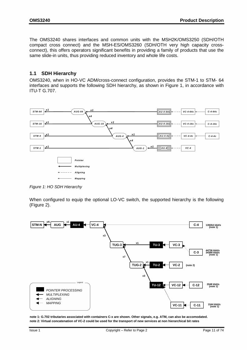
1.1 SDH HierarchyOMS3240, when in HO-VC ADM/cross-connect configuration, provides the STM-1 to STM- 64interfaces and supports the following SDH hierarchy, as shown in Figure 1, in accordance withITU-T G.707.
AU-4
AU-4-4c
AU-4-16c
AU-4-64c VC-4-64c
VC-4-16c
VC-4-4c
VC-4
Aligning
Mapping
Pointeri
Multip lexing
C-4-4c
x1
x1
x1
STM-64
STM-16
STM-4
STM-1
x1x1
x1
x1
x1
x4
AUG-64
AUG-16
AUG-4
AUG-1
C-4-64c
C-4-16cx1
x4
x4
Figure 1: HO SDH Hierarchy
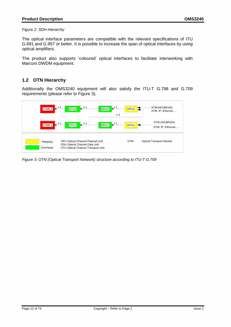
When configured to equip the optional LO-VC switch, the supported hierarchy is the following(Figure 2).
.............
TUG-3
TUG-2
TU-3
TU-2
TU-12
VC-3
VC-2
VC-12
VC-11 C-11
C-12
C-3
STM-N AUG AU-4 VC-4 C-4
......
......
......
......
......
POINTER PROCESSINGMULTIPLEXING
MAPPINGALIGNING
Legend
note 1: G.702 tributaries associated with containers C-x are shown. Other signals, e.g. ATM, can also be accomodated. note 2: Virtual concatenation of VC-2 could be used for the transport of new services at non hierarchical bit rates
139264 kbit/s (note 1)
34368 kbit/s (note 1)
44736 kbit/s
(note 2)
2048 kbit/s (note 1)
1544 kbit/s (note 1)
xN x1
x3
x7
x1
x1
x3
Product Description OMS3240
Page 12 of 74 Copyright – Refer to Page 2 Issue 1
Figure 2: SDH Hierarchy
The optical interface parameters are compatible with the relevant specifications of ITUG.691 and G.957 or better. It is possible to increase the span of optical interfaces by usingoptical amplifiers.
The product also supports ‘coloured’ optical interfaces to facilitate interworking withMarconi DWDM equipment.
1.2 OTN Hierarchy
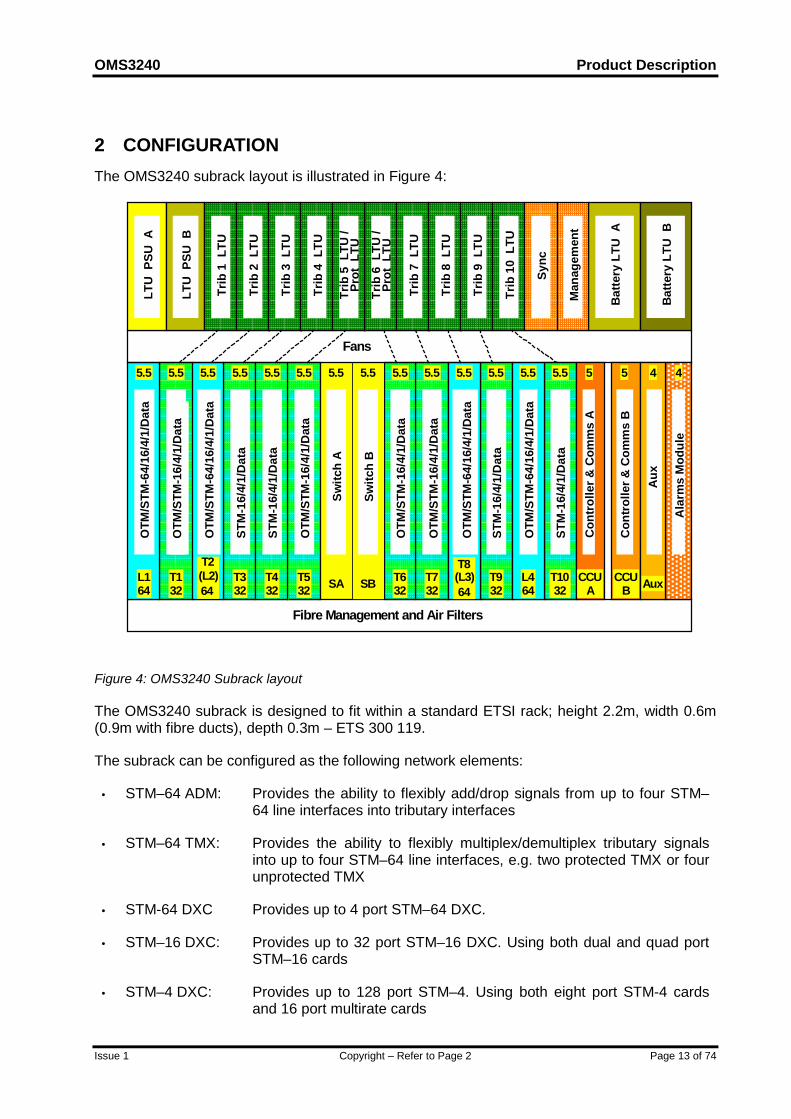
Additionally the OMS3240 equipment will also satisfy the ITU-T G.798 and G.709requirements (please refer to Figure 3).
OTM0.2 ODU2 OPU2x 1OTU2 x 1 STM-64/CBR10GATM, IP, Ethernet, ...
OTM0.1 ODU1 OPU1x 1OTU1 x 1 STM-16/CBR2G5
ATM, IP, Ethernet, ...
x 1
x 1
OPU Optical Channel Payload UnitODU Optical Channel Data UnitOTU Optical Channel Transport Unit
Mapping
Overhead
OTM Optical Transport Module
x 4
Figure 3: OTN (Optical Transport Network) structure according to ITU-T G.709
OMS3240 Product Description
Issue 1 Copyright – Refer to Page 2 Page 13 of 74
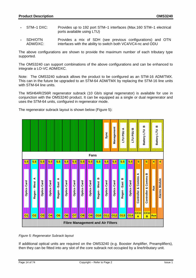
2 CONFIGURATIONThe OMS3240 subrack layout is illustrated in Figure 4:
T132
5.5
Fibre Management and Air Filters
5.55.5 5.5 5.5 5.5 5.55.55.5 5.5
L164
5.5 5.55.5 5.5 5.5
T2(L2)64
T8(L3)64
L464
T332
T432
T532
T632
T732
T932
T1032SA SB
Fans
OTM
/STM
-16/
4/1/
Dat
a
Switc
h A
Switc
h B
STM
-16/
4/1/
Dat
a
Batte
ry L
TU B
Batte
ry L
TU A
OTM
/STM
-64/
16/4
/1/D
ata
5 5
CCUA
CCUB
44
Aux
Con
trol
ler &
Com
ms
A
Con
trol
ler &
Com
ms
B
Ala
rms
Mod
ule
Aux
LTU
PSU
A
LTU
PSU
B
Trib
1 L
TU
Trib
2 L
TU
Trib
3 L
TU
Trib
4 L
TU
Trib
6 L
TU /
Prot
LTU
Trib
5 L
TU /
Prot
LTU
Sync
Man
agem
ent
Trib
7 L
TU
Trib
8 L
TU
Trib
9 L
TU
Trib
10
LTU
STM-64/16/4/1/Data
OTM
/STM
-16/
4/1/
Data
OTM
/STM
-64/
16/4
/1/D
ata
STM
-16/
4/1/
Dat
a
OTM
/STM
-16/
4/1/
Dat
a
OTM
/STM
-16/
4/1/
Dat
a
OTM
/STM
-64/
16/4
/1/D
ata
STM
-16/
4/1/
Dat
a
STM
-16/
4/1/
Dat
a
OTM
/STM
-64/
16/4
/1/D
ata
Figure 4: OMS3240 Subrack layout
The OMS3240 subrack is designed to fit within a standard ETSI rack; height 2.2m, width 0.6m(0.9m with fibre ducts), depth 0.3m – ETS 300 119.
The subrack can be configured as the following network elements:
• STM–64 ADM: Provides the ability to flexibly add/drop signals from up to four STM–64 line interfaces into tributary interfaces
• STM–64 TMX: Provides the ability to flexibly multiplex/demultiplex tributary signalsinto up to four STM–64 line interfaces, e.g. two protected TMX or fourunprotected TMX
• STM-64 DXC Provides up to 4 port STM–64 DXC.
• STM–16 DXC: Provides up to 32 port STM–16 DXC. Using both dual and quad portSTM–16 cards
• STM–4 DXC: Provides up to 128 port STM–4. Using both eight port STM-4 cardsand 16 port multirate cards
Product Description OMS3240
Page 14 of 74 Copyright – Refer to Page 2 Issue 1
• STM–1 DXC: Provides up to 192 port STM–1 interfaces (Max.160 STM–1 electricalports available using LTU)
• SDH/OTNADM/DXC:
Provides a mix of SDH (see previous configurations) and OTNinterfaces with the ability to switch both VC4/VC4-nc and ODU
The above configurations are shown to provide the maximum number of each tributary typesupported.
The OMS3240 can support combinations of the above configurations and can be enhanced tointegrate a LO-VC ADM/DXC.
Note: The OMS3240 subrack allows the product to be configured as an STM-16 ADM/TMX.This can in the future be upgraded to an STM-64 ADM/TMX by replacing the STM-16 line unitswith STM-64 line units.
The MSH64R/256R regenerator subrack (10 Gb/s signal regenerator) is available for use inconjunction with the OMS3240 product. It can be equipped as a single or dual regenerator anduses the STM-64 units, configured in regenerator mode.
The regenerator subrack layout is shown below (Figure 5):
Opt
ics
Car
d
Rege
n - W
est
A
Reg
en -
East
A
Opt
ics
Car
d
Opt
ics
Car
d
Opt
ics
Car
d
Opt
ics
Car
d
Opt
ics
Car
d
Opt
ics
Car
d
Fibre Management and Air Filters
FansAu
x
Con
trolle
r & C
omm
s A
Con
trol
ler &
Com
ms
B
Ala
rms
Mod
ule
Bat
tery
LTU
B
LTU
PSU
A
Sync
Man
agem
ent
LTU
PSU
B
Bat
tery
LTU
B
Reg
en -
East
B
Reg
en -
Wes
t B
Opt
ics
Car
d
Opt
ics
Car
d
Opt
ics
Car
d
5.5 5.55.5 5.5 5.5 5.5 5.55.55.5 5.55.5 5.55.5 5.5 5.5 5 5 44
O3 O4O2 O7O5 O6 O8O1 O11 O12O10O9 O13 O14CCU
ACCU
B Aux
Figure 5: Regenerator Subrack layout
If additional optical units are required on the OMS3240 (e.g. Booster Amplifier, Preamplifiers),then they can be fitted into any slot of the core subrack not occupied by a line/tributary unit.
OMS3240 Product Description
Issue 1 Copyright – Refer to Page 2 Page 15 of 74
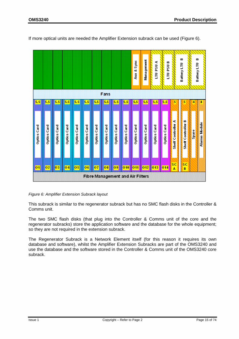
If more optical units are needed the Amplifier Extension subrack can be used (Figure 6).
Figure 6: Amplifier Extension Subrack layout
This subrack is similar to the regenerator subrack but has no SMC flash disks in the Controller &Comms unit.
The two SMC flash disks (that plug into the Controller & Comms unit of the core and theregenerator subracks) store the application software and the database for the whole equipment;so they are not required in the extension subrack.
The Regenerator Subrack is a Network Element itself (for this reason it requires its owndatabase and software), whilst the Amplifier Extension Subracks are part of the OMS3240 anduse the database and the software stored in the Controller & Comms unit of the OMS3240 coresubrack.
Product Description OMS3240
Page 16 of 74 Copyright – Refer to Page 2 Issue 1
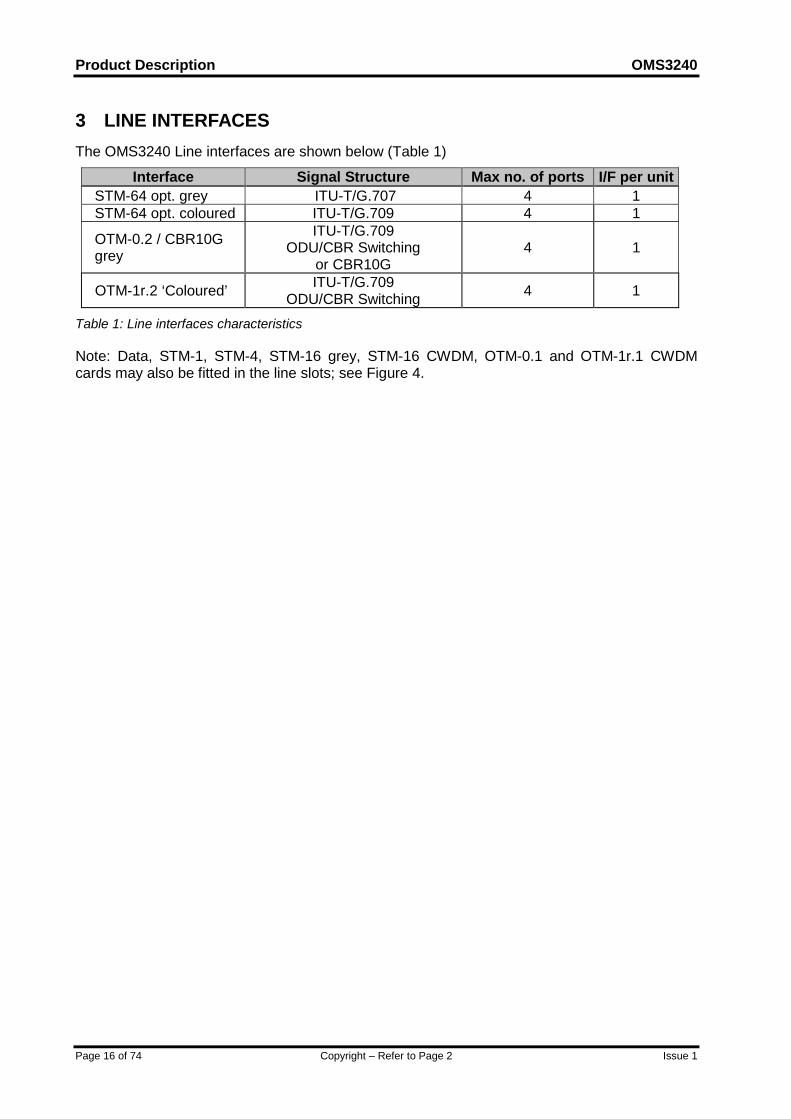
3 LINE INTERFACESThe OMS3240 Line interfaces are shown below (Table 1)
Interface Signal Structure Max no. of ports I/F per unitSTM-64 opt. grey ITU-T/G.707 4 1STM-64 opt. coloured ITU-T/G.709 4 1
OTM-0.2 / CBR10Ggrey
ITU-T/G.709ODU/CBR Switching
or CBR10G4 1
OTM-1r.2 ‘Coloured’ ITU-T/G.709ODU/CBR Switching 4 1
Table 1: Line interfaces characteristics
Note: Data, STM-1, STM-4, STM-16 grey, STM-16 CWDM, OTM-0.1 and OTM-1r.1 CWDMcards may also be fitted in the line slots; see Figure 4.
OMS3240 Product Description
Issue 1 Copyright – Refer to Page 2 Page 17 of 74
4 TRIBUTARY INTERFACES
4.1 Interfaces and protection
OMS3240 can be equipped with compatible 'plug-in' units allowing access to different SDH,data and OTN signal interfaces.
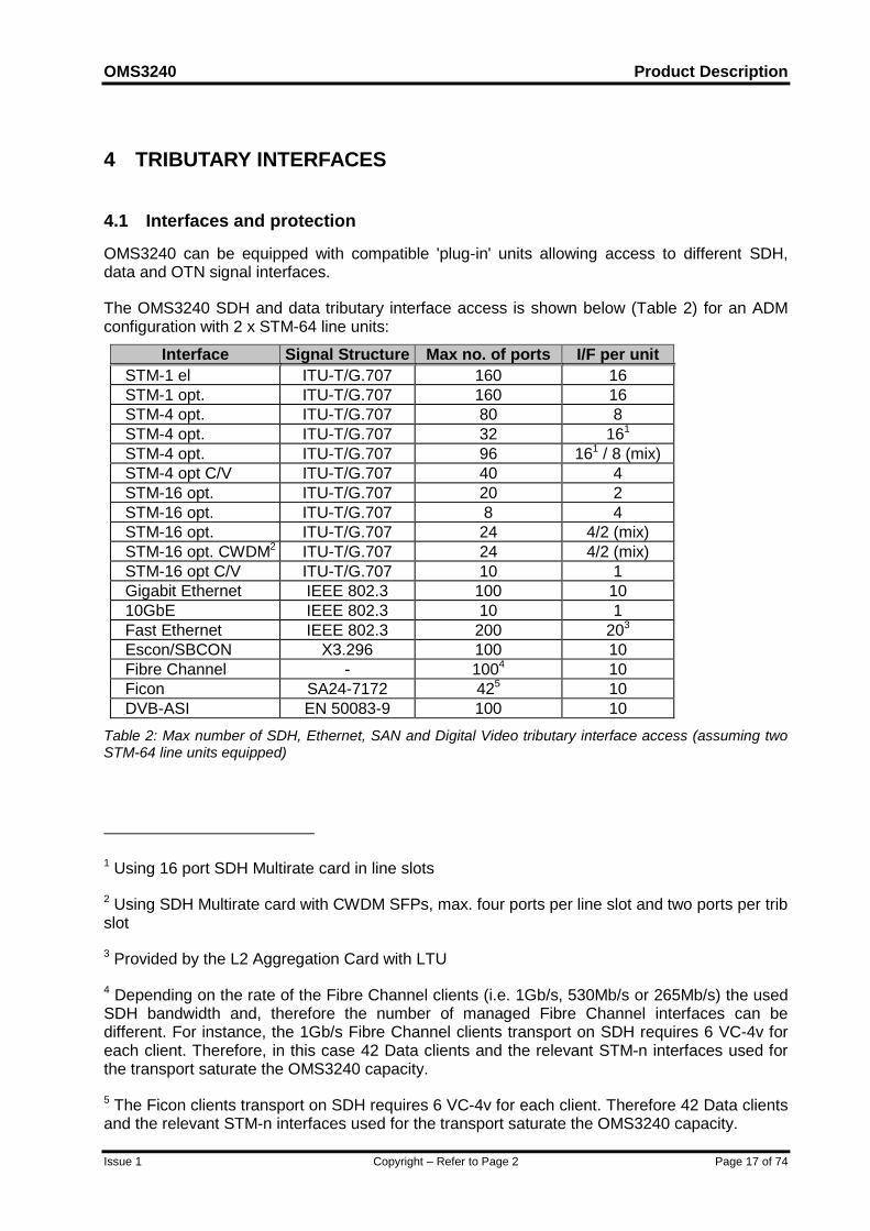
The OMS3240 SDH and data tributary interface access is shown below (Table 2) for an ADMconfiguration with 2 x STM-64 line units:
Interface Signal Structure Max no. of ports I/F per unitSTM-1 el ITU-T/G.707 160 16STM-1 opt. ITU-T/G.707 160 16STM-4 opt. ITU-T/G.707 80 8STM-4 opt. ITU-T/G.707 32 161
STM-4 opt. ITU-T/G.707 96 161 / 8 (mix)STM-4 opt C/V ITU-T/G.707 40 4STM-16 opt. ITU-T/G.707 20 2STM-16 opt. ITU-T/G.707 8 4STM-16 opt. ITU-T/G.707 24 4/2 (mix)STM-16 opt. CWDM2 ITU-T/G.707 24 4/2 (mix)STM-16 opt C/V ITU-T/G.707 10 1Gigabit Ethernet IEEE 802.3 100 1010GbE IEEE 802.3 10 1Fast Ethernet IEEE 802.3 200 203
Escon/SBCON X3.296 100 10Fibre Channel - 1004 10Ficon SA24-7172 425 10DVB-ASI EN 50083-9 100 10
Table 2: Max number of SDH, Ethernet, SAN and Digital Video tributary interface access (assuming twoSTM-64 line units equipped)
1 Using 16 port SDH Multirate card in line slots
2 Using SDH Multirate card with CWDM SFPs, max. four ports per line slot and two ports per tribslot
3 Provided by the L2 Aggregation Card with LTU
4 Depending on the rate of the Fibre Channel clients (i.e. 1Gb/s, 530Mb/s or 265Mb/s) the usedSDH bandwidth and, therefore the number of managed Fibre Channel interfaces can bedifferent. For instance, the 1Gb/s Fibre Channel clients transport on SDH requires 6 VC-4v foreach client. Therefore, in this case 42 Data clients and the relevant STM-n interfaces used forthe transport saturate the OMS3240 capacity.
5 The Ficon clients transport on SDH requires 6 VC-4v for each client. Therefore 42 Data clientsand the relevant STM-n interfaces used for the transport saturate the OMS3240 capacity.
Product Description OMS3240
Page 18 of 74 Copyright – Refer to Page 2 Issue 1
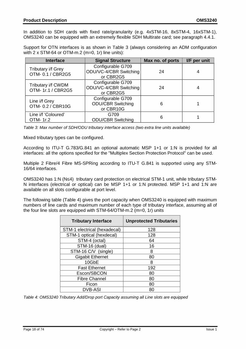
In addition to SDH cards with fixed rate/granularity (e.g. 4xSTM-16, 8xSTM-4, 16xSTM-1),OMS3240 can be equipped with an extremely flexible SDH Multirate card; see paragraph 4.4.1.
Support for OTN interfaces is as shown in Table 3 (always considering an ADM configurationwith 2 x STM-64 or OTM-m.2 (m=0, 1r) line units):
Interface Signal Structure Max no. of ports I/F per unit
Tributary i/f GreyOTM- 0.1 / CBR2G5
Configurable G709ODU/VC-4/CBR Switching
or CBR2G524 4
Tributary i/f CWDMOTM- 1r.1 / CBR2G5
Configurable G709ODU/VC-4/CBR Switching
or CBR2G524 4
Line i/f GreyOTM- 0.2 / CBR10G
Configurable G709ODU/CBR Switching
or CBR10G6 1
Line i/f ‘Coloured’OTM- 1r.2
G709ODU/CBR Switching 6 1
Table 3: Max number of SDH/ODU tributary interface access (two extra line units available)
Mixed tributary types can be configured.
According to ITU-T G.783/G.841 an optional automatic MSP 1+1 or 1:N is provided for allinterfaces: all the options specified for the "Multiplex Section Protection Protocol" can be used.
Multiple 2 Fibre/4 Fibre MS-SPRing according to ITU-T G.841 is supported using any STM-16/64 interfaces.
OMS3240 has 1:N (N≤4) tributary card protection on electrical STM-1 unit, while tributary STM-N interfaces (electrical or optical) can be MSP 1+1 or 1:N protected. MSP 1+1 and 1:N areavailable on all slots configurable at port level.
The following table (Table 4) gives the port capacity when OMS3240 is equipped with maximumnumbers of line cards and maximum number of each type of tributary interface, assuming all ofthe four line slots are equipped with STM-64/OTM-m.2 (m=0, 1r) units
Tributary Interface Unprotected Tributaries
STM-1 electrical (hexadecal) 128STM-1 optical (hexdecal) 128
STM-4 (octal) 64STM-16 (dual) 16
STM-16 C/V (single) 8Gigabit Ethernet 80
10GbE 8Fast Ethernet 192
Escon/SBCON 80Fibre Channel 80
Ficon 80DVB-ASI 80
Table 4: OMS3240 Tributary Add/Drop port Capacity assuming all Line slots are equipped
OMS3240 Product Description
Issue 1 Copyright – Refer to Page 2 Page 19 of 74
4.2 Synchronisation Interfaces
Two dedicated outputs and two dedicated input interfaces are provided:
• 2048 kHz (G.703 sect. 13)
• 2048 kbit/s (framed/unframed G.706/G.703 sect. 9)
Electrical interfaces are available for synchronisation on OMS3240. In all cases the interfacesare independent.
4.3 Electrical Interfaces Characteristics
The characteristics for the tributary electrical interfaces are in compliance with the following ITU-T Recommendations:
• STM-1 according to G.703
OMS3240 supports the following electrical Data interfaces:
• Fast Ethernet 100BaseT;
• Gigabit Ethernet 1000BaseT.
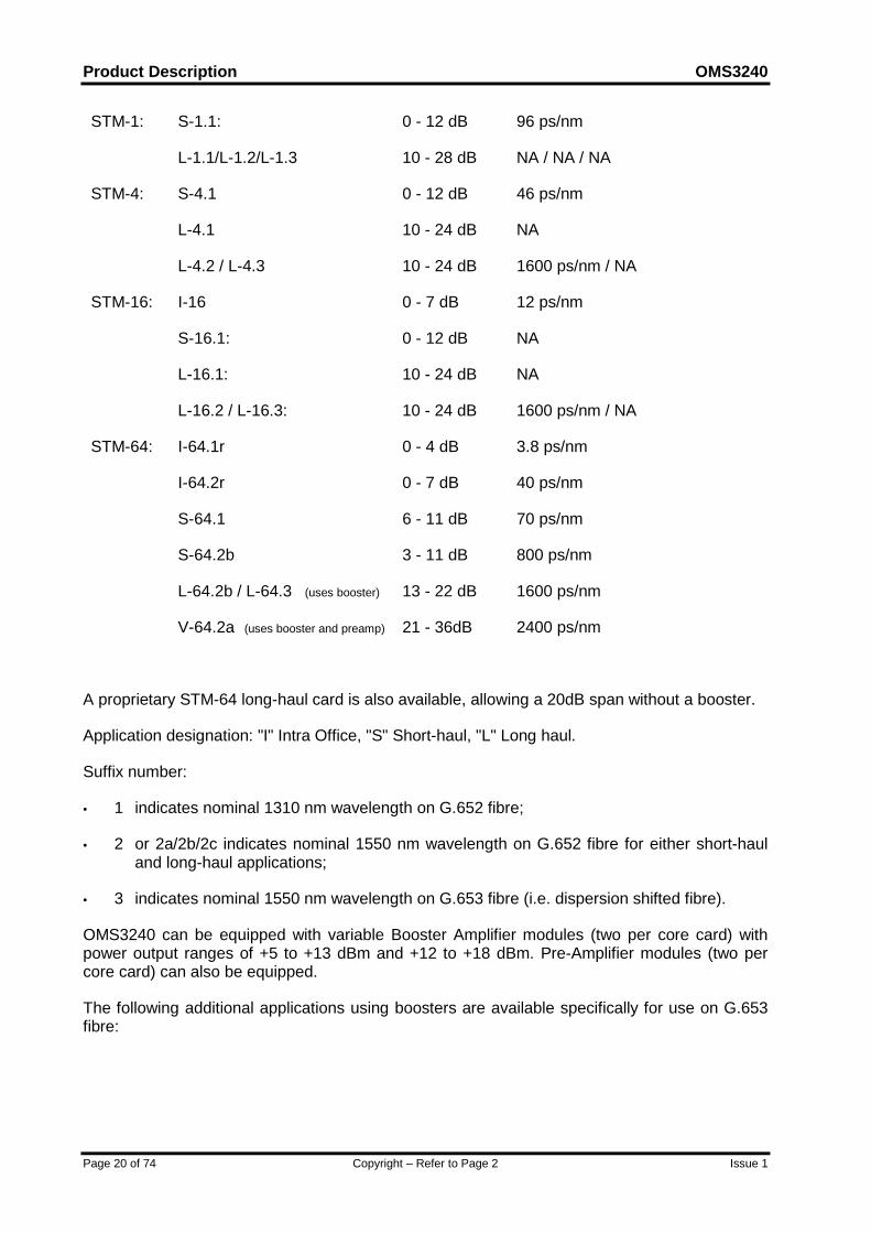
4.4 Optical Interfaces Characteristics
The performance of the optical interfaces is in compliance with ITU-T G.691, G.957 or better.The provided optical interfaces, their attenuation ranges and maximum dispersion are as follows(NA means Not Applicable):
Product Description OMS3240
Page 20 of 74 Copyright – Refer to Page 2 Issue 1
STM-1: S-1.1:
L-1.1/L-1.2/L-1.3
0 - 12 dB
10 - 28 dB
96 ps/nm
NA / NA / NA
STM-4: S-4.1
L-4.1
L-4.2 / L-4.3
0 - 12 dB
10 - 24 dB
10 - 24 dB
46 ps/nm
NA
1600 ps/nm / NA
STM-16: I-16
S-16.1:
L-16.1:
L-16.2 / L-16.3:
0 - 7 dB
0 - 12 dB
10 - 24 dB
10 - 24 dB
12 ps/nm
NA
NA
1600 ps/nm / NA
STM-64: I-64.1r
I-64.2r
S-64.1
S-64.2b
L-64.2b / L-64.3 (uses booster)
V-64.2a (uses booster and preamp)
0 - 4 dB
0 - 7 dB
6 - 11 dB
3 - 11 dB
13 - 22 dB
21 - 36dB
3.8 ps/nm
40 ps/nm
70 ps/nm
800 ps/nm
1600 ps/nm
2400 ps/nm
A proprietary STM-64 long-haul card is also available, allowing a 20dB span without a booster.
Application designation: "I" Intra Office, "S" Short-haul, "L" Long haul.
Suffix number:
• 1 indicates nominal 1310 nm wavelength on G.652 fibre;
• 2 or 2a/2b/2c indicates nominal 1550 nm wavelength on G.652 fibre for either short-hauland long-haul applications;
• 3 indicates nominal 1550 nm wavelength on G.653 fibre (i.e. dispersion shifted fibre).
OMS3240 can be equipped with variable Booster Amplifier modules (two per core card) withpower output ranges of +5 to +13 dBm and +12 to +18 dBm. Pre-Amplifier modules (two percore card) can also be equipped.
The following additional applications using boosters are available specifically for use on G.653fibre:

OMS3240 Product Description
Issue 1 Copyright – Refer to Page 2 Page 21 of 74
STM-16: V-16.3 (uses booster)
V-16.3b17 (uses booster)
21 - 36 dB
28 - 43 dB
1600 ps/nm
1600 ps/nm
STM-64: V-64.3 (uses booster and preamp)
U-64.3b12 (uses booster and preamp)
U-64.3b17 (uses booster and preamp)
21 - 37 dB
23 - 39 dB
28 - 44 dB
1600 ps/nm
1600 ps/nm
1600 ps/nm
For STM-64 opt. Interfaces, if Non-dispersion Shifted Fibre is used (i.e. G.652 fibre) fixeddispersion compensation fibre (DCF) is provided where required.
OMS3240 supports DWDM applications by integrating the following 10Gb/s units, both of whichhave transmit wavelengths tunable over 16 wavelengths with 50GHz spacing:
• 1xSTM-64 OOB FEC unit supporting a G.709 digital wrapper. This unit providesOTU2/ODU2/RS/MS termination and VC-4 switching;
• 1xOTM-1r.2 unit supporting OTU2 term, ODU1 multiplexing and ODU2/ODU1/VC-4switching;
In addition OMS3240 is open to support CWDM 2.5Gb/s applications by integrating the 4xOTM-1r.1 unit (supporting OTU1 term and ODU1/VC-4 switching) or the SDH Multirate card. As thesecards are provided with hot-pluggable optical transceivers, they can be equipped with SFPmodules operating on different lambdas. 2.5Gb/s DWDM applications will also be possible usingthe same units when suitable SFPs become available.
The basic CWDM application consists of 4 or 8 unidirectional channels with wavelengthsranging from 1471nm to 1611nm with 20nm spacing according to ITU-T RecommendationG.694.2. In order to provide a single subrack CWDM solution, the associated mux and demuxfilters can be housed in LTU slots within the OMS3240 subrack. Alternatively, they can behoused in an external all-passive filter subrack. The 8 channel CWDM filter is also available withan expansion port in order to provide channel upgrade with no traffic interruption, allowing morewavelengths to be accommodated, up to 16 in total, depending on the fibre type and linkcharacteristics. Both Short Haul and Long Haul CWDM interfaces are available, covering theapplications defined in Recommendation G.695. A span loss of typically 22dB (or 21dB) can beachieved for an unamplified single span point to point 4 (or 8) channel Long Haul configurationover standard G.652 fibre.
The performance of the OMS3240 Optical Line Interfaces can be improved by the FEC function.The FEC is particularly useful for long-distance systems that suffer from noise accumulation,optical non-linear effects and/or polarisation effects. In Band FEC code operates within the SDHline rates and improves the BER performance. The FEC function can dynamically provide anevaluation of the system margins relatively to the required level of performance. If maintenanceof the line appears to be necessary, it can then be planned before any effective degradation ofthe transmission.
The FEC function essentially comprises:
• FEC encoder in the transmitting Terminal equipment that accepts information bits and addsredundancy, producing encoded data at higher bit rate;
Product Description OMS3240
Page 22 of 74 Copyright – Refer to Page 2 Issue 1
• FEC decoder in the receiving Terminal equipment that performs the error correction whileextracting the redundancy to regenerate the data that was encoded by the FEC encoder.
Implementation of the In Band FEC (IB FEC) function uses a Hamming code without modifyingthe bit rate of the STM-64 signal.
Both a proprietary IB FEC and IB FEC as defined in ITU-T G.707 are supported by OMS3240.
Implementation of the Out of Band FEC (OOB FEC) function uses the OTU-2 frame structure(as detailed in figure 11-1/G.709) and is supported by OTM-m.2 (m=0, 1r) units.
It is possible to enable/disable the FEC function by a command entered by NMS or LCT.
In case of fibre break an automatic laser shutdown is provided to avoid danger caused by theemission of laser light. The procedure for automatic laser shutdown and restart is based on ITU-T/G. 958 (Appendix 2) and on ITU-T/G.664.
If the Optical Amplifiers are equipped, an automatic power shutdown is provided. Theprocedures for automatic power shutdown and restart are based on ITU-T G. 681, Section 10and on ITU-T G.664.
4.4.1 SDH Multirate card
Three variants of this card provide a maximum of 16, 8 and 4 ports respectively, where eachport is equipped with hot-pluggable transceivers. Such transceivers are in the form of SFPmodules supporting STM-1, STM-4 and STM-16 with different optical reaches as follows, thusproviding a very high degree of flexibility both in terms of traffic management and fibre linklength. Each port may be equipped at any time, even after the card has been put into service,without any impairment to the ports already configured.
• STM-1 S-1.1, L-1.1 or L-1.2
• STM-4 S-4.1, L-4.1 or L-4.2
• STM-16 I-16, S-16.1, L-16.1 or L-16.2
SFP electrical modules for STM-1 are foreseen when commercially available.The SDH Multirate cards can be equipped and programmed to support many differentconfigurations. In their basic form, the cards can be configured to support the following full,single-rate configurations (MULTIPORT functionality) which may also be used to replaceprevious SDH card types:• 4xSTM-16;• 8xSTM-4;• 16xSTM-1
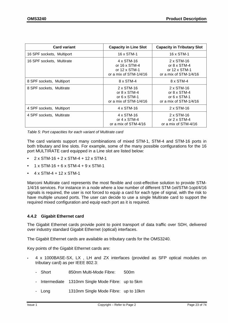
Then with the addition of a hardware key to enable the MULTIRATE functionality, mixedconfigurations with STM-1 el, STM-1 opt, STM-4 and STM-16 are also supported, with theconstraint not to exceed 1 x STM-64-equivalent bandwidth. Please note that, when the card isused in tributary slots of OMS3240, its maximum bandwidth will be further limited both in single-rate and multi-rate configurations to 2 x STM-16 equivalent. The following table summarises themaximum capacity for each variant of the card:
OMS3240 Product Description
Issue 1 Copyright – Refer to Page 2 Page 23 of 74
Card variant Capacity in Line Slot Capacity in Tributary Slot
16 SPF sockets, Multiport 16 x STM-1 16 x STM-1
16 SPF sockets, Multirate 4 x STM-16or 16 x STM-4or 12 x STM-1
or a mix of STM-1/4/16
2 x STM-16or 8 x STM-4
or 12 x STM-1or a mix of STM-1/4/16
8 SPF sockets, Multiport 8 x STM-4 8 x STM-4
8 SPF sockets, Multirate 2 x STM-16or 8 x STM-4or 6 x STM-1
or a mix of STM-1/4/16
2 x STM-16or 8 x STM-4or 6 x STM-1
or a mix of STM-1/4/16
4 SPF sockets, Multiport 4 x STM-16 2 x STM-16
4 SPF sockets, Multirate 4 x STM-16or 4 x STM-4
or a mix of STM-4/16
2 x STM-16or 2 x STM-4
or a mix of STM-4/16
Table 5: Port capacities for each variant of Multirate card
The card variants support many combinations of mixed STM-1, STM-4 and STM-16 ports inboth tributary and line slots. For example, some of the many possible configurations for the 16port MULTIRATE card equipped in a Line slot are listed below:
• 2 x STM-16 + 2 x STM-4 + 12 x STM-1
• 1 x STM-16 + 6 x STM-4 + 9 x STM-1
• 4 x STM-4 + 12 x STM-1
Marconi Multirate card represents the most flexible and cost-effective solution to provide STM-1/4/16 services. For instance in a node where a low number of different STM-1el/STM-1opt/4/16signals is required, the user is not forced to equip a card for each type of signal, with the risk tohave multiple unused ports. The user can decide to use a single Multirate card to support therequired mixed configuration and equip each port as it is required.
4.4.2 Gigabit Ethernet card
The Gigabit Ethernet cards provide point to point transport of data traffic over SDH, deliveredover industry standard Gigabit Ethernet (optical) interfaces.
The Gigabit Ethernet cards are available as tributary cards for the OMS3240.
Key points of the Gigabit Ethernet cards are:
• 4 x 1000BASE-SX, LX , LH and ZX interfaces (provided as SFP optical modules ontributary card) as per IEEE 802.3:
- Short 850nm Multi-Mode Fibre: 500m
- Intermediate 1310nm Single Mode Fibre: up to 5km
- Long 1310nm Single Mode Fibre: up to 10km
Product Description OMS3240
Page 24 of 74 Copyright – Refer to Page 2 Issue 1
- Extra Long 1550nm Single Mode Fibre: up to 80km
• Supports LAN interconnect services (Transparent LAN Service - EPL)
• Cheaper interconnect option for the end user than adding TDM interfaces to his LANswitch/router
• Can upgrade host OMS3240 platform in service, without affecting other services
• Increase range of services and hence revenue from SDH delivery platforms
• No need for a separate LAN switch or router to provide the Gigabit Ethernet interface(s)
• Provide monitored delivery of Ethernet transport services (remotely accessible counters,giving service level information to the operator)
• No need for a separate LAN switch or router to monitor delivery performance
• Map each interface into n x VC-4 capacity across the SDH network
• Remotely configurable, in n x VC-4 steps, up to 1 Gigabit per Ethernet port (7 x VC-4)
• LAPS (X.86) )/GFP-F used to map Ethernet frames into SDH
• Ethernet frames from each port can each be mapped into either a separate VC-4, or eachinto a VC-4-nv virtually concatenated payload, where n is 2 to 7
• LCAS supported
• VC-4-7v provides Gigabit Ethernet transport throughput
• Alternatively, frames can be mapped from each port into a separate VC-4-4c link
• Transparent transport of VLAN frames
• SDH transport protection retained
• Gigabit Ethernet line protection is available
4.4.3 Multi-Protocol Data card
The Multi-Protocol Data card is a tributary card, providing 10 Multi-Protocol user interfaces orone 10 GbE user interface, which maps client signals into SDH Virtual Containers. The type andnumber of interfaces to be equipped is flexible through the use of pluggable modules (i.e. SFPand XFP). The card provides 11 Sockets: ten can be used when the card is configured as Multi-protocol, while one is dedicated to provide 10GbE services. The types of client signals that canbe configured for each Multi-Protocol user interface are divided into three main categories:Ethernet traffic (FastE and GbE), SAN traffic (ESCON/SBCON, Fibre Channel/FICON) andDigital Video (DVB-ASI).
Each client signal is mapped into a single Virtual Concatenation Group through GFPencapsulation. Framed GFP mapping is applied to FastE, GbE and 10 GbE. This type ofmapping permits interworking with the Aggregation Data card. The card is open to supportTransparent GFP mapping for GbE. Transparent GFP mapping is applied to SAN traffic andDVB-ASI.
OMS3240 Product Description
Issue 1 Copyright – Refer to Page 2 Page 25 of 74
The services offered by this card are the same describe in the previous section.
The bandwidth of the SDH Virtual Containers can be flexibly configured in order to carryefficiently Ethernet traffic. Furthermore LCAS bandwidth management protocol can be applied.
Depending on the client signal bandwidth, the GFP encapsulated signals can be transported inthe following SDH containers: VC-4, VC-4-nv (n=1 to 64).
4.4.4 Aggregation Data card
The extensive usage of Ethernet connections across the SDH network requires the SDHnetwork to increase functionality to match more and more with the Ethernet L2 needs. TheAggregation Data card covers these needs.
4.4.4.1 L2 transport
Multiplexed Ethernet access:
When a larger number of connections is required per SDH head end node and per core switchor router, using a simple point to point transport service across the SDH network, a break pointwill be reached in network and equipment costs.
At this site an Aggregation card – presenting these multiple connections as logical flows over asingle physical interface – will become the more cost-effective solution. The benefits in utilisingsuch a card include:
• Single connection to core switch/router means less cabling, which is then easier to handleand maintain in the equipment room.
• Single card to present several remote customers to the core switch/router, which meansmore remote customer served and/or fewer slots used.
• Installation and operational cost savings, as further logical connections can be addedremotely once the single interface is installed – no need to make a return visit to addEthernet link, or to cable multiple Ethernet links on day one.
Ethernet multiplexing into SDH VCGs:
When a number of flows all go (or can be designed to go) from a single site to another, the useof a dedicated VCG per Ethernet flow does not cover all possible services that can be present inthe transported Ethernet signal. In the Ethernet Private Line, the service offered to the Ethernetflow can be characterised at SDH level for example via the different type of protectionconfigured (not protected, LCAS protected, SNCP protected, re-routed, fast re-routed viaGMPLS…) but in any case a dedicated bandwidth is allocated to it (CIR).
At both ends of the VCG trail (or just at one end if at the other end the flows are presented asaggregated to a core switch/router) an Aggregation card will allow more Ethernet flows to bemultiplexed into a single VCG. The benefits in utilising such a card include:
• Increasing the granularity of the network service, no longer limited by the VC-12/VC-4granularity; in a single VC more than one customer flow can now be transported;

Product Description OMS3240
Page 26 of 74 Copyright – Refer to Page 2 Issue 1
• Increasing the number of services provided; not only a CIR can be set up for an Ethernetflow, but also an EIR can be set up in conjunction with the CIR or just as a unique agreedservice.
• Increasing the network bandwidth usage; a service using the EIR can take advantage ofbandwidth available in a particular time period, optimising the overall usage of the SDHavailable bandwidth.
Mixed configurations of multiplexed Ethernet access and Ethernet multiplexing into SDH VCGcan also be achieved.
These services are referred as virtual private line (EVPL)
In addition to these, the aggregation card covers EPL applications as in the 4xGigE card.
4.4.4.2 L2 switching:
Layer 2 Switching introduces address learning mechanisms into the transport functions.
The SDH network no longer provides only private lines between local area networks, but alsoprovides an Ethernet bridged network within the operator network.
This service is referred to as virtual private LAN service (EVPLAN).
The Aggregation card configured for the L2 switching function avoids the need for an externalEthernet switch device. The benefits in utilising such a card include:
• Increasing the level of service provided by the SDH operator to the Ethernet customer
• Installation and operational cost savings, as SDH and switching functions are concentratedin one site and one device.
The card has on Ethernet side 8 GigE plus 4 FastE/Eth interfaces on the front of the card and12 additional FastE/Eth are provided in the LTU area. On the SDH side a bandwidth of 32 STM-1 equivalents is provided, giving a total capacity of 10G full duplex. The Ethernet flows aremapped SDH side via GFP-F into VCGs that can be VC-4-nv, VC-3-nv and VC-12-nv, with orwithout LCAS.
Please note that the card is able to terminate trails both at VC-4 level and at LO-VC level,avoiding the use of the LO switch where all LO VCs pertaining the Ethernet flows are presentedin the right number of VC-4s.
The card inter-works with Ethernet cards using GFP-F mapping across all platforms within theMarconi portfolio, both ‘mapper’ cards (i.e. providing just EPL, like 4xGigE or multiprotocol cardsinto OMS3240/2K) and ‘aggregation’ cards.
According to the importance of high quality data networks for business applications theperformance management is based on several mechanisms:
• on the SDH performance management according to ITU-T G. 826 and 829
• on the Ethernet port management counters based on RMON and RFC2665
• additional SDH-class data transport performance and alarm management based on trafficmeasurements like packet loss and defect frames, which allows the monitoring of thecomplete customer traffic flow similar to the way it is already provided for SDH networks.
OMS3240 Product Description
Issue 1 Copyright – Refer to Page 2 Page 27 of 74
4.4.5 OTM cards
OMS3240 supports 10G and a 4x2G5 cards able to handle OTM-0/1r.k signals. The followingtypes of cards are available:
• 4xCBR2G5/OTM-0.1;
• 1xCBR10G/OTM-0.2;
• 1xOTM-1r.2.
The first two types are double bit-rate cards. Each port of the card can be configured to accepttwo different signals from the line:
• CBR2G5 and CBR10G: signals with a Constant Bit Rate of 2 488 320 Kbit/s ± 20 ppm and9 953 280 kbit/s ± 20 ppm respectively. Examples of these signals are the STM-16 or OC-192, for the CBR2G5, and the STM-64 or OC-192 signal, for the CBR10G, as defined inG.709;
• OTM-0.1 and OTM-0.2 signals as defined in G.709.
In addition a specific 'Coloured' 10Gb/s card version is available (i.e. 1xOTM-1r.2), while theequivalent for the 2.5Gb/s application (i.e. 4xOTM-1r.1) can be obtained by plugging a'Coloured' SFP on the card.
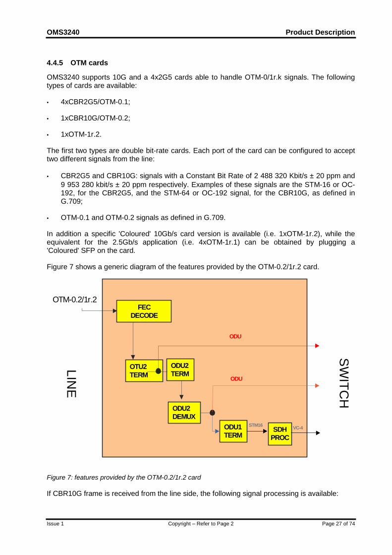
Figure 7 shows a generic diagram of the features provided by the OTM-0.2/1r.2 card.
FECDECODE
OTU2TERM
SDHPROC
ODU1TERM
ODU
ODU
STM16
ODU2DEMUX
ODU2TERM
OTM-0.2/1r.2
VC-4
LINE
SWITC
H
Figure 7: features provided by the OTM-0.2/1r.2 card
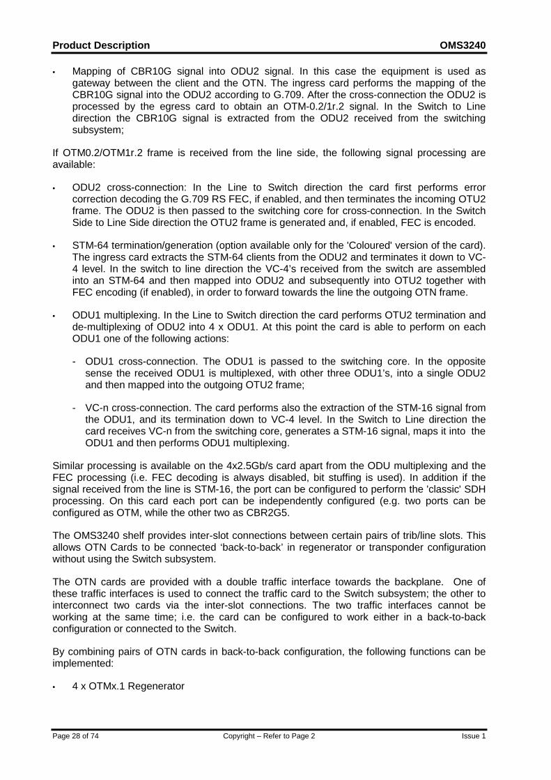
If CBR10G frame is received from the line side, the following signal processing is available:
Product Description OMS3240
Page 28 of 74 Copyright – Refer to Page 2 Issue 1
• Mapping of CBR10G signal into ODU2 signal. In this case the equipment is used asgateway between the client and the OTN. The ingress card performs the mapping of theCBR10G signal into the ODU2 according to G.709. After the cross-connection the ODU2 isprocessed by the egress card to obtain an OTM-0.2/1r.2 signal. In the Switch to Linedirection the CBR10G signal is extracted from the ODU2 received from the switchingsubsystem;
If OTM0.2/OTM1r.2 frame is received from the line side, the following signal processing areavailable:
• ODU2 cross-connection: In the Line to Switch direction the card first performs errorcorrection decoding the G.709 RS FEC, if enabled, and then terminates the incoming OTU2frame. The ODU2 is then passed to the switching core for cross-connection. In the SwitchSide to Line Side direction the OTU2 frame is generated and, if enabled, FEC is encoded.
• STM-64 termination/generation (option available only for the 'Coloured' version of the card).The ingress card extracts the STM-64 clients from the ODU2 and terminates it down to VC-4 level. In the switch to line direction the VC-4’s received from the switch are assembledinto an STM-64 and then mapped into ODU2 and subsequently into OTU2 together withFEC encoding (if enabled), in order to forward towards the line the outgoing OTN frame.
• ODU1 multiplexing. In the Line to Switch direction the card performs OTU2 termination andde-multiplexing of ODU2 into 4 x ODU1. At this point the card is able to perform on eachODU1 one of the following actions:
- ODU1 cross-connection. The ODU1 is passed to the switching core. In the oppositesense the received ODU1 is multiplexed, with other three ODU1’s, into a single ODU2and then mapped into the outgoing OTU2 frame;
- VC-n cross-connection. The card performs also the extraction of the STM-16 signal fromthe ODU1, and its termination down to VC-4 level. In the Switch to Line direction thecard receives VC-n from the switching core, generates a STM-16 signal, maps it into theODU1 and then performs ODU1 multiplexing.
Similar processing is available on the 4x2.5Gb/s card apart from the ODU multiplexing and theFEC processing (i.e. FEC decoding is always disabled, bit stuffing is used). In addition if thesignal received from the line is STM-16, the port can be configured to perform the 'classic' SDHprocessing. On this card each port can be independently configured (e.g. two ports can beconfigured as OTM, while the other two as CBR2G5.
The OMS3240 shelf provides inter-slot connections between certain pairs of trib/line slots. Thisallows OTN Cards to be connected ‘back-to-back’ in regenerator or transponder configurationwithout using the Switch subsystem.
The OTN cards are provided with a double traffic interface towards the backplane. One ofthese traffic interfaces is used to connect the traffic card to the Switch subsystem; the other tointerconnect two cards via the inter-slot connections. The two traffic interfaces cannot beworking at the same time; i.e. the card can be configured to work either in a back-to-backconfiguration or connected to the Switch.
By combining pairs of OTN cards in back-to-back configuration, the following functions can beimplemented:
• 4 x OTMx.1 Regenerator
OMS3240 Product Description
Issue 1 Copyright – Refer to Page 2 Page 29 of 74
• 1 x OTMx.2 Regenerator/transponder (the transponder function is obtained by connectingtwo ‘coloured’ traffic cards, OTM1r.2)
• 4 x OTMx.1 into 1 x OTMx.2 Multiplexer.
Product Description OMS3240
Page 30 of 74 Copyright – Refer to Page 2 Issue 1
5 MAPPING & MULTIPLEXING FUNCTIONSThe Mapping and Multiplexing functions provide the capability of mapping, aligning andmultiplexing bi-directional logical channels between the SDH physical interfaces. TheMultiplexing structure used in the equipment is according to ETSI/ETS 300 147 and ITU-TG.707.
OMS3240 can support the concatenation of up to sixty-four (64) contiguous AU-4s according toG.707, using concatenation indication.
OMS3240 also supports the concatenation of contiguous AU-4s, by converting them intovirtually concatenated AU-4s using the STM-16/STM-4 contiguous to virtual conversion card.This card supports both AU-4-16c to 16v conversion and AU-4-4c to 4v conversion. The STM-16/4 C/V card uses hot-pluggable optical transceivers and can be configured as:
• 1xSTM-16 AU4-16c/16v or AU4-4c/4v converter;
• 4xSTM-4 AU4-4c/4v converter.
The use of this unit at the edge of a network, permits a VC-4-4c/16c service to be provided evenif the network doesn't support the routing of VC-4-4c/16c containers,
ODUk (k=1,2) cross-connections and Mapping and Multiplexing functions defined in G.709 aresupported.
SONET transport over SDH can be supported, ie STS-3c carried as AU-4, STS-12c carried asAU-4-4c, STS-48c carried as AU-4-16c and STS-192c carried as AU-4-64c. The SS bits in theAU-4 pointer can be configured to support this. Note, however, that AU-3/TU-3 conversion is notsupported.
OMS3240 Product Description
Issue 1 Copyright – Refer to Page 2 Page 31 of 74
6 SECTION AND PATH OVERHEAD BYTES PROCESSINGThe Section and Path Overhead bytes are defined according to ITU-T G.707 and ETSI/ ETS300 417-1-1.
The OH bytes, depending on their main use, are categorised as follows:
• Dedicated to specific use: these bytes are processed as required by internationalstandards
• Accessible: these bytes are accessible to the user via dedicated interfaces,for the purpose of data transport
• Settable: all these bytes can be set to the same values (all zeros or allones) and ignored at the receiver
The Accessible bytes are made available through the interfaces specified in Section 11(Services) and can be chosen from the list below:
• all SOH bytes of the STM-1 signals;
• SOH bytes of the first STM-1 (i.e. having defined each SOH byte as S (a,b,c), a: 1..3, 5..9,b: 1..9, c: 1) of the STM-N signals;
• VC4 POH
6.1 SOH Bytes Description
6.1.1 Regeneration Section Overhead (RSOH)
A1, A2 FRAMING; they are used to define frame alignment
J0 SECTION TRACE IDENTIFIER; it identifies the access point where theSTM-N signal is sourced
B1 REGENERATOR SECTION ERROR MONITORING; it is used forregenerator section error monitoring (BIP-8 parity check code)
E1 ENGINEERING ORDER WIRE; it may provide a 64 Kbit/s order wirechannel for voice communication
F1 USER CHANNEL; it is reserved for user purposes
D1÷D3 (DCCR) DATA COMMUNICATION CHANNEL; it provides a 192 Kb/s datacommunication channel
Z0 SPARE BYTES are allocated for functions not yet defined
Others RESERVED FOR NATIONAL USE;
MEDIA DEPENDANT
Product Description OMS3240
Page 32 of 74 Copyright – Refer to Page 2 Issue 1
UNMARKED
6.1.2 Multiplex Section Overhead (MSOH)
B2 MULTIPLEX SECTION ERROR MONITORING; it is used for multiplexsection error monitoring (BIP-Nx24 parity check code).
K1, K2 (b1÷b5) AUTOMATIC PROTECTION SWITCHING CHANNEL; it is used for MSPand MS-SPRing protocol management.
K2 (b6÷b8) MS-REMOTE DEFECT INDICATION MS-AIS; it is used for alarmindication and MS-SPRing protocol management
D4÷D12(DCCM)
DATA COMMUNICATION CHANNEL; they provides a 576 Kb/s datacommunication channel
E2 ENGINEERING ORDER-WIRE; it may provide a 64 Kb/s order-wirechannel for voice communication
S1 (b5÷b8) SYNCHRONISATION STATUS; they transport the SSM (SynchronisationStatus Message)
M1 MS-REMOTE ERROR INDICATION; it transports the number of errorsdetected using B2 bytes
Others RESERVED FOR NATIONAL USE;
UNMARKED
6.2 POH Bytes Description
6.2.1 VC-4 / VC-4Xc / VC-4-Xv POH
J1 PATH TRACE; it is used to transmit repetitively a High Order Path AccessPoint Identifier
B3 PATH ERROR MONITORING; it is used for path error monitoring (BIP-8parity check code).
C2 SIGNAL LABEL; it indicates the composition of the VC3/4 payload
G1 PATH STATUS; it conveys back to a path originator the path terminatingstatus and performance
F2-F3 PATH USER CHANNEL; they are allocated for user communicationpurpose
H4 POSITION AND SEQUENCE INDICATOR; it provides a multi-frame andsequence indicator for virtual VC-4 concatenation
K3 (b1÷b4) AUTOMATIC PROTECTION SWITCHING (APS) CHANNEL; they areprovisionally allocated for APS signalling for network protection of High
OMS3240 Product Description
Issue 1 Copyright – Refer to Page 2 Page 33 of 74
Order Path Level
K3 (b5÷b8) SPARE; they are allocated for future purpose
N1 NETWORK OPERATOR; it has been allocated for tandem connectionmonitoring function
6.2.2 Connection Supervision Functions
OMS3240 has been conceived to support Higher Order Supervisory-Unequipped functionality.
The Higher Order Supervisory-Unequipped function comprises the atomic functions HigherOrder Supervisory unequipped termination source (Sns_TT_So) and sink (Sns_TT_Sk), as theyare defined by ITU-T revised Draft G. 783 Recommendation.
The Higher Order Supervisory-Unequipped function enables supervision of unassigned HOconnections on VC-4 paths.
6.2.3 Tandem Connection Monitoring
OMS3240 is open to support VC-4 Tandem Connection Monitoring functionality according toETSI/ETS 300-417-4-1.
A VC-4 Tandem Connection is set-up to provide monitoring for a segment of a path, e.g. fromwhere a path enters an operator's domain until it leaves that domain or is terminated. Specificinformation is added by the source function at the ingress of the Tandem Connection. Thisinformation is then extracted together with other path overheads by the sink function and isused to establish defect detection and performance monitoring for the path segment associatedto the Tandem Connection.

Product Description OMS3240
Page 34 of 74 Copyright – Refer to Page 2 Issue 1
7 OTN OVERHEAD BYTE PROCESSINGThe OUTk and ODUk Layers Overhead bytes are managed according to ITU-T G.709 and ITU-T G. 798.
OMS3240 Product Description
Issue 1 Copyright – Refer to Page 2 Page 35 of 74
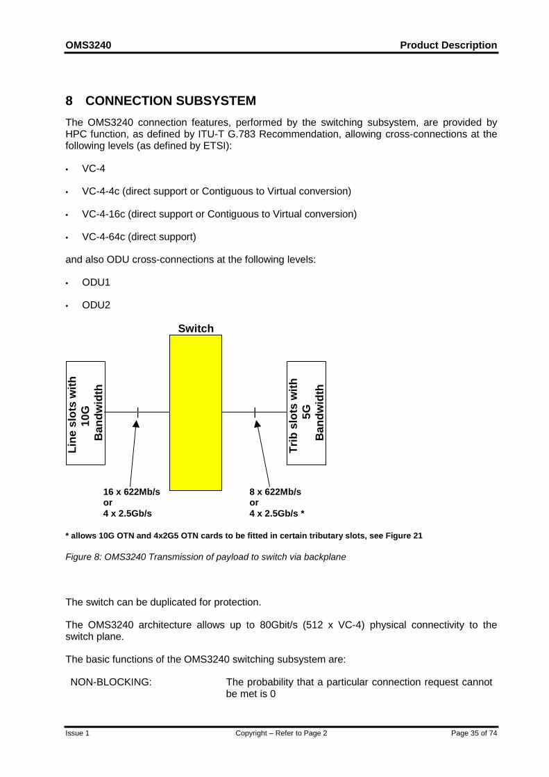
8 CONNECTION SUBSYSTEMThe OMS3240 connection features, performed by the switching subsystem, are provided byHPC function, as defined by ITU-T G.783 Recommendation, allowing cross-connections at thefollowing levels (as defined by ETSI):
• VC-4
• VC-4-4c (direct support or Contiguous to Virtual conversion)
• VC-4-16c (direct support or Contiguous to Virtual conversion)
• VC-4-64c (direct support)
and also ODU cross-connections at the following levels:
• ODU1
• ODU2
Line
slo
ts w
ith10
GB
andw
idth
Trib
slo
ts w
ith5G
Ban
dwid
th
| |
Switch
8 x 622Mb/sor4 x 2.5Gb/s *
16 x 622Mb/sor4 x 2.5Gb/s
* allows 10G OTN and 4x2G5 OTN cards to be fitted in certain tributary slots, see Figure 21
Figure 8: OMS3240 Transmission of payload to switch via backplane
The switch can be duplicated for protection.
The OMS3240 architecture allows up to 80Gbit/s (512 x VC-4) physical connectivity to theswitch plane.
The basic functions of the OMS3240 switching subsystem are:
NON-BLOCKING: The probability that a particular connection request cannotbe met is 0
Product Description OMS3240
Page 36 of 74 Copyright – Refer to Page 2 Issue 1
FULL CONNECTIVITY: It is possible to connect any input to each free output
TIMING TRANSPARENCYi.e. no slip:
Each outgoing switched channel contains the same timinginformation as it did at input port before switching
TIME SEQUENCE INTEGRITY(concatenated payloads):
Concatenated payloads are switched without breaking thetime sequence integrity
ASSURED CORRECTNESSOF CROSS-CONNECTIONS:
Correct cross-connections between the right traffic ports
The switching subsystem can be configured to the following connection types:
• Unidirectional
• Bi-directional
• Broadcast
• Drop and Continue for SNCP
• Drop and Continue for MS-SPRing
• Loopback
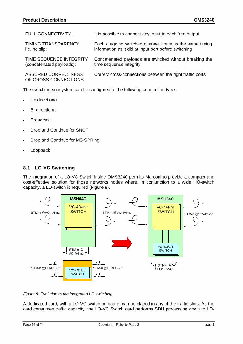
8.1 LO-VC Switching
The integration of a LO-VC Switch inside OMS3240 permits Marconi to provide a compact andcost-effective solution for those networks nodes where, in conjunction to a wide HO-switchcapacity, a LO-switch is required (Figure 9).
MSH64CMSH64C
STM-n @VC-4/4-nc STM-n @VC-4/4-nc
STM-n @HO/LO-VC STM-n @HO/LO-VC
STM-n @VC-4/4-nc
STM-n @HO/LO-VC
STM-n @VC-4/4-nc
VC-4/4-ncSWITCH
VC-4/4-ncSWITCH
VC-4/3/2/1SWITCH
VC-4/3/2/1SWITCH
Figure 9: Evolution to the integrated LO switching
A dedicated card, with a LO-VC switch on board, can be placed in any of the traffic slots. As thecard consumes traffic capacity, the LO-VC Switch card performs SDH processing down to LO-
OMS3240 Product Description
Issue 1 Copyright – Refer to Page 2 Page 37 of 74
VC level (i.e. included TU Pointer processing and LO-VC OH monitoring) of STM-n signalsconnected on the front of the unit.
The integration of a LO-VC Switch inside OMS3240 allows cross-connections down to VC-3,VC-2, and VC-12 levels and it is open to support VC-11 cross-connection as well.
Up to 8 Sockets are present on the card and can be equipped with different SFP modules toobtain the following configurations:
• 2xSTM-16;
• 8xSTM-4;
• 8xSTM-1
Mixed configurations with STM-1, STM-4 and STM-16 are also supported, with the constraintnot to exceed 2 xSTM-16-equivalent bandwidth.
The LO-VC Switch can be considered a hybrid card: it merges on the same card both theswitching and the traffic processing features.
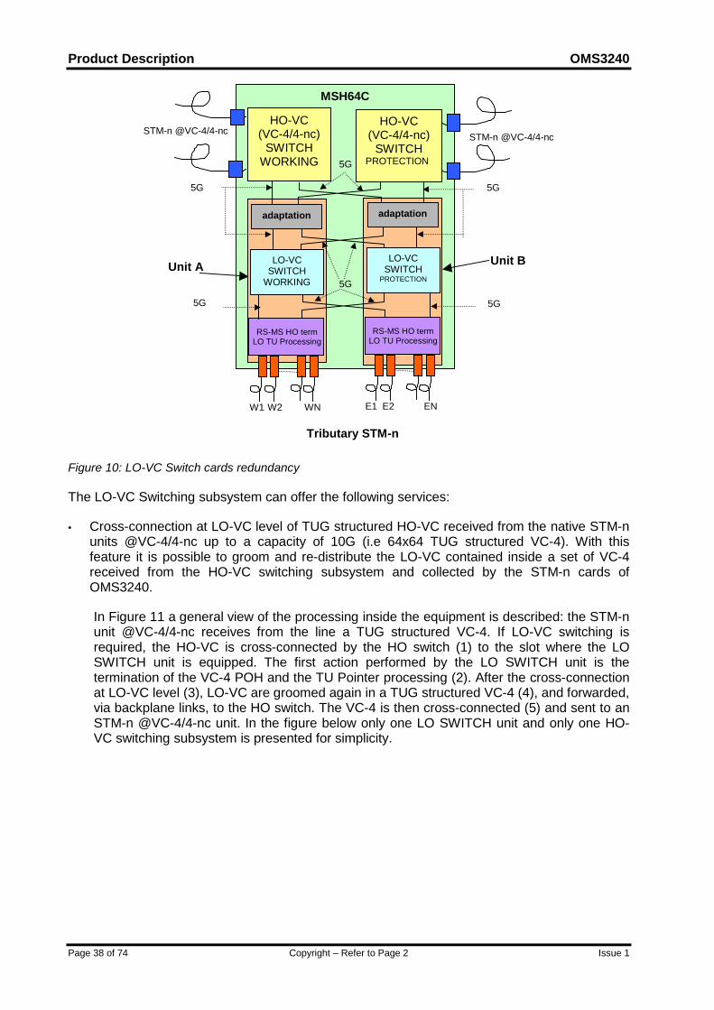
For redundancy purposes OMS3240 can be equipped with two LO-VC Switch cards (Unit A andUnit B): one of them shall operate as “Working” and the other as “Protection”. In addition, inorder to provide the maximum availability each LO-VC Switch card is connected to both the"Working" and the "Protecting" HO-VC switching subsystem and cross connect the tributarytraffic collected by the companion card: both Unit A and Unit B switch the traffic collected byW1,..Wn, E1,..En (Figure 10). The traffic collected by W1,..Wn is processed down to LO-VClevel (i.e. TU pointer processing and LO-VC monitoring included) on Unit A, while the trafficcollected by E1,..En is processed on Unit B. The two units then exchanges the processed datavia backplane links, therefore the two Units of the LO-VC Switching subsystem must be fitted inprecise slots of OMS3240 to provide the redundancy.
Product Description OMS3240
Page 38 of 74 Copyright – Refer to Page 2 Issue 1
MSH64C
STM-n @VC-4/4-nc STM-n @VC-4/4-ncHO-VC
(VC-4/4-nc)SWITCH
WORKING
adaptation adaptation
HO-VC(VC-4/4-nc)
SWITCHPROTECTION
5G
5G
RS-MS HO termLO TU Processing
RS-MS HO termLO TU Processing
W1 W2 E1WN E2 EN
5G
5G
5G5G
Unit A Unit B
Tributary STM-n
LO-VCSWITCH
PROTECTION
LO-VCSWITCH
WORKING
Figure 10: LO-VC Switch cards redundancy
The LO-VC Switching subsystem can offer the following services:
• Cross-connection at LO-VC level of TUG structured HO-VC received from the native STM-nunits @VC-4/4-nc up to a capacity of 10G (i.e 64x64 TUG structured VC-4). With thisfeature it is possible to groom and re-distribute the LO-VC contained inside a set of VC-4received from the HO-VC switching subsystem and collected by the STM-n cards ofOMS3240.
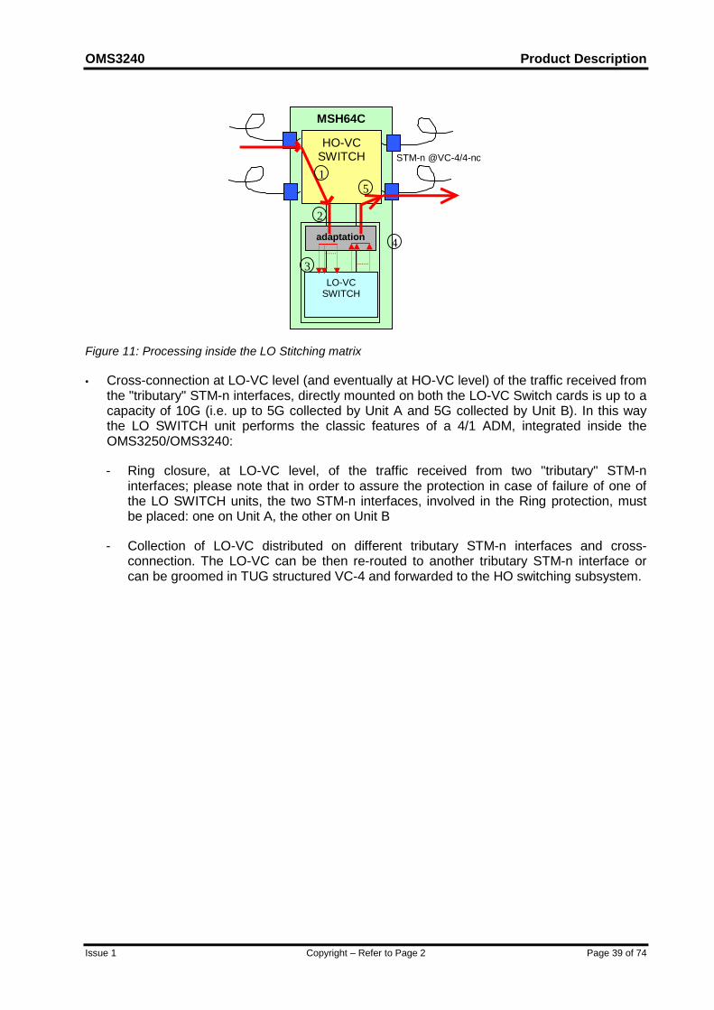
In Figure 11 a general view of the processing inside the equipment is described: the STM-nunit @VC-4/4-nc receives from the line a TUG structured VC-4. If LO-VC switching isrequired, the HO-VC is cross-connected by the HO switch (1) to the slot where the LOSWITCH unit is equipped. The first action performed by the LO SWITCH unit is thetermination of the VC-4 POH and the TU Pointer processing (2). After the cross-connectionat LO-VC level (3), LO-VC are groomed again in a TUG structured VC-4 (4), and forwarded,via backplane links, to the HO switch. The VC-4 is then cross-connected (5) and sent to anSTM-n @VC-4/4-nc unit. In the figure below only one LO SWITCH unit and only one HO-VC switching subsystem is presented for simplicity.
OMS3240 Product Description
Issue 1 Copyright – Refer to Page 2 Page 39 of 74
MSH64C
HO-VCSWITCH STM-n @VC-4/4-nc
LO-VCSWITCH
adaptation
1
2
3
4
5
Figure 11: Processing inside the LO Stitching matrix
• Cross-connection at LO-VC level (and eventually at HO-VC level) of the traffic received fromthe "tributary" STM-n interfaces, directly mounted on both the LO-VC Switch cards is up to acapacity of 10G (i.e. up to 5G collected by Unit A and 5G collected by Unit B). In this waythe LO SWITCH unit performs the classic features of a 4/1 ADM, integrated inside theOMS3250/OMS3240:
- Ring closure, at LO-VC level, of the traffic received from two "tributary" STM-ninterfaces; please note that in order to assure the protection in case of failure of one ofthe LO SWITCH units, the two STM-n interfaces, involved in the Ring protection, mustbe placed: one on Unit A, the other on Unit B
- Collection of LO-VC distributed on different tributary STM-n interfaces and cross-connection. The LO-VC can be then re-routed to another tributary STM-n interface orcan be groomed in TUG structured VC-4 and forwarded to the HO switching subsystem.
Product Description OMS3240
Page 40 of 74 Copyright – Refer to Page 2 Issue 1
9 USAGE OF OMS3240 AS OMS3260 PORT SHELFThe usage of OMS3240 as port subrack for OMS3260 (960 Gb/s capacity), involves thereplacement of the Switch units with Switch interface units.
In the OMS3260 port rack mode, the traffic is also distributed in byte mode.
Each Switch interface unit is connected to the OMS3260 core via ribbon cables each containing8 fibres (4Tx and 4Rx), the traffic is transmitted at STM-16.
Up to 24 port subracks can be added to OMS3260, each port subrack is allocated a shelfnumber (SN Id). This is configured and displayed on the alarm module.
Each Port Subrack can be provided with Expansion Subracks available for the OMS3240.
OMS3240 Product Description
Issue 1 Copyright – Refer to Page 2 Page 41 of 74
10 NETWORK APPLICATIONS AND PROTECTIONSThe OMS3240 cross connect system allows the connection of complex network configurations,such as rings, chains and stars. These topologies can also be mixed.
The switching functions and the range of possible tributaries allow flexible reconfiguration of thetraffic as far as both the destination and the capacity of the transmitted circuits are concerned.
The possible protection features at network level are:
• MSP protection on STM-N line and tributary interfaces according to ITU-T/G.841;
• "Sub-Network Connection Protection", according to ITU-T/G.841, at VC-4, VC-3, VC-2 andVC-12 level;
• "MS-SPRing" protection on STM-16 and STM-64 rings according to ITU-T/G.841.
• "Ring Interworking Protection", according to ITU-T/G.842;
• Fast Restoration via ASTN;
• OTN Protections (i.e. ODUk SNC/I and SNC/N).
Also mixed protection can be applied, for example MS SPRING and SNC-P, MS-SPRing andFast Restoration or ODUk SNC/x and SNC-P.
10.1 MSP protection
The MSP function provides protection for the STM-N signal against channel-associated failureswithin a multiplex section. All possible options specified for the "Multiplex Section Protection(MSP) Protocol" (bytes K1 and K2), as defined in ITU-T/G.783 and G.841, can be used.
The following criteria may be used at the receive end for switching to the protection path:
• Signal Fail (LOS, LOF, MS-AIS, Excessive BER) at section level;
• Signal Degrade (BER exceeds a preset threshold in the range of 10-5 to 10-9);
• Command from the Local Terminal or from ServiceOn Optical Element Manager andManagement System.
On STM-1/4/16/64 tributary interfaces, MSP protection is available, using a 1+1 or 1:Narchitecture; with N up to 4.
When the MSP 1:N (N≥1) is provided, optional extra traffic is supported.
10.2 MS-SPRing Protection
OMS3240 equipment provides the MS-SPRing ("SDH Multiplex Section Shared ProtectionRing") protection mechanism. Its general features are defined in ITU-T Rec. 803, while the
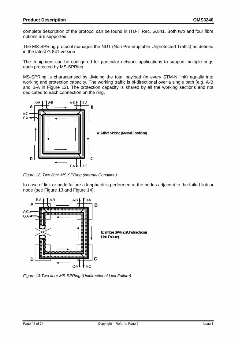
Product Description OMS3240
Page 42 of 74 Copyright – Refer to Page 2 Issue 1
complete description of the protocol can be found in ITU-T Rec. G.841. Both two and four fibreoptions are supported.
The MS-SPRing protocol manages the NUT (Non Pre-emptable Unprotected Traffic) as definedin the latest G.841 version.
The equipment can be configured for particular network applications to support multiple ringseach protected by MS-SPRing.
MS-SPRing is characterised by dividing the total payload (in every STM-N link) equally intoworking and protection capacity. The working traffic is bi-directional over a single path (e.g. A-Band B-A in Figure 12). The protection capacity is shared by all the working sections and notdedicated to each connection on the ring.
A B
CDC-A A-C
A-B B-AA-BB-A
A-CC-A
a: 2-fibre SPRing (Normal Condition)
Figure 12: Two fibre MS-SPRing (Normal Condition)
In case of link or node failure a loopback is performed at the nodes adjacent to the failed link ornode (see Figure 13 and Figure 14).
A B
CDC-A A-C
A-B B-AA-BB-A
A-CC-A
b: 2-fibre SPRing (UnidirectionalLink Failure)
Figure 13:Two fibre MS-SPRing (Unidirectional Link Failure)
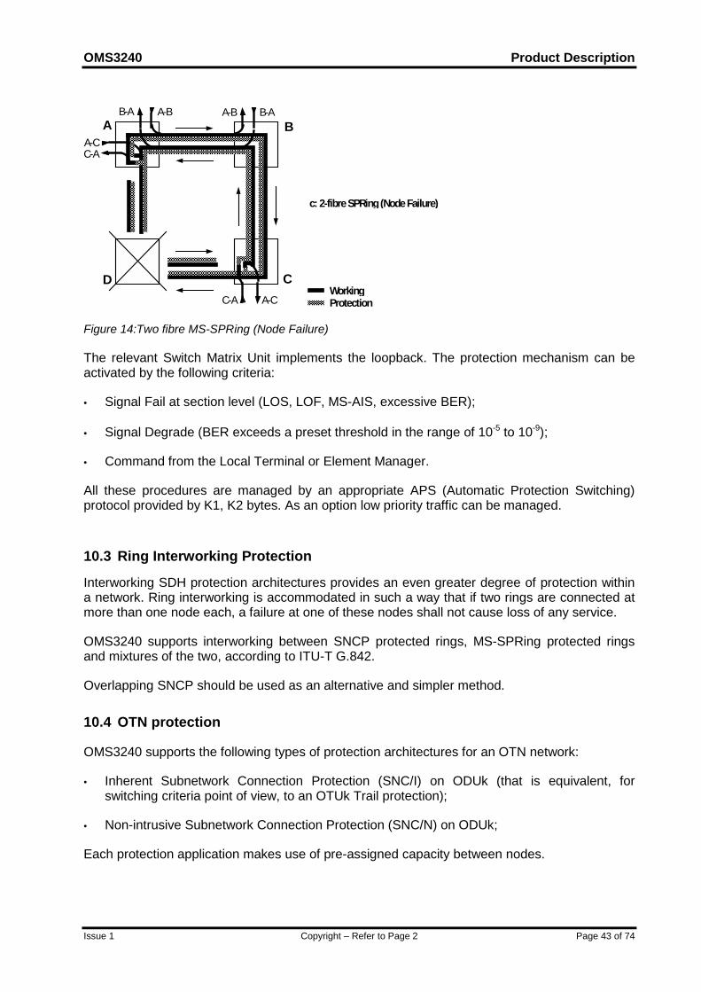
OMS3240 Product Description
Issue 1 Copyright – Refer to Page 2 Page 43 of 74
A B
CDC-A A-C
A-B B-AA-BB-A
A-CC-A
WorkingProtection
c: 2-fibre SPRing (Node Failure)
Figure 14:Two fibre MS-SPRing (Node Failure)
The relevant Switch Matrix Unit implements the loopback. The protection mechanism can beactivated by the following criteria:
• Signal Fail at section level (LOS, LOF, MS-AIS, excessive BER);
• Signal Degrade (BER exceeds a preset threshold in the range of 10-5 to 10-9);
• Command from the Local Terminal or Element Manager.
All these procedures are managed by an appropriate APS (Automatic Protection Switching)protocol provided by K1, K2 bytes. As an option low priority traffic can be managed.
10.3 Ring Interworking Protection
Interworking SDH protection architectures provides an even greater degree of protection withina network. Ring interworking is accommodated in such a way that if two rings are connected atmore than one node each, a failure at one of these nodes shall not cause loss of any service.
OMS3240 supports interworking between SNCP protected rings, MS-SPRing protected ringsand mixtures of the two, according to ITU-T G.842.
Overlapping SNCP should be used as an alternative and simpler method.
10.4 OTN protection
OMS3240 supports the following types of protection architectures for an OTN network:
• Inherent Subnetwork Connection Protection (SNC/I) on ODUk (that is equivalent, forswitching criteria point of view, to an OTUk Trail protection);
• Non-intrusive Subnetwork Connection Protection (SNC/N) on ODUk;
Each protection application makes use of pre-assigned capacity between nodes.

Product Description OMS3240
Page 44 of 74 Copyright – Refer to Page 2 Issue 1
10.5 Sub-network connection protection
The "Sub-Network Connection Protection" is defined in ITU-T Rec. G.803 and ITU-T Rec.G.841.
When OMS3240 systems are connected in a subnetwork (e.g. a ring topology) the relevant VC-4 of the signal to be protected can be protected, by transmitting it from the input tributary to twooutput interfaces. At the receive side, the available or better-quality signal is selected.
The switching between the two directions is based on the following criteria:
• AU-AIS and AU-LOP alarms at the VC level (inherent monitoring);
• Error performances (BIP information), payload and routing correctness (Unequipped Signaland Trace Identifier) at the VC level (non intrusive monitoring);
• Command from the Local Terminal or from Element Manager.
In this way, the channel is protected against any single failure in the subnetwork.
The following ODUk protection architectures are supported:
• 1+1 unidirectional SNC/N and SNC/I
In these architectures, a permanent bridge is utilised at the transmit end. At the receiverend, a protection switch is realized by selecting one of the signals based on purely localinformation.
For protection switching criteria, non-intrusive (SNC/N) or server layer (SNC/I) monitoringshall be used.
• 1+1 bi-directional SNC/N and SNC/I
In these architectures, a permanent bridge is utilised at the transmit end. At the receiveend, a protection switch is realised by selecting one of the signals based on local or remoteinformation. For protection switching criteria, non-intrusive (SNC/N) or server layer (SNC/I)monitoring is used.
These types of protection use the automatic protection switching protocol (APS).
• 1:N an SNC/I protection
In this architecture N working subnetwork connections that are to be protected share anadditional subnetwork connection for protection purposes. In a normal condition, thisprotection capacity can be used to carry lower priority “extra traffic”. This extra traffic itself isnot protected and is to be replaced by higher priority working traffic under failure conditions.This architecture requires the APS as protection control.
For protection switching criteria, server layer (SNC/I) monitoring is used.
The architecture can be unidirectional or bi-directional.
For 1+1 architecture the revertive or non-revertive mode of operations is available.
For each type of protection, manual external command is available to the operator.
OMS3240 Product Description
Issue 1 Copyright – Refer to Page 2 Page 45 of 74
10.6 OS Restoration
It is possible to perform network protection using rerouting. This protection scheme is mainlyoperated by the network management system using the capabilities of cross-connectionreconfiguration offered by OMS3240.
Spare capacity is reserved on each link of a meshed network in order to provide alternativeroutes on which traffic can be transported. In case of cable break the traffic transported by thefailed link is redirected along pre-programmed or on-line calculated alternative routes using theavailable reserved capacity.
10.7 Fast Restoration
As well as conventional SDH protection schemes the OMS3240 will support ITU-T(ASON/ASTN) based fast network restoration. This method of protection is particularly effectivein mesh network architectures.
The OMS3240 will simultaneously support all SDH protection schemes and network restorationmaking it the ideal switching solution for operators wishing to migrate from one scheme toanother. The Marconi solution offers full scalability to meet the needs of large operators whotypically could have hundreds of dynamic elements in their networks.
Spare capacity is reserved on each link of a meshed network, in order to provide alternativeroutes on which traffic can be transported. In case of cable break the traffic transported by thefailed link is redirected along pre-programmed or on-line calculated alternative routes using theavailable reserved capacity.
This protection scheme can be applied at any cross-connected level, i.e. VC4, VC4-nc andODU.
Product Description OMS3240
Page 46 of 74 Copyright – Refer to Page 2 Issue 1
11 AUTOMATIC SWITCHING TRANSPORT NETWORK with OMS3240The OMS32xx family may be introduced into an existing network to provide a new layer oftransport network where the concept of ASTN can be applied to achieve faster trail routing,connection set-up and tear down and fast network restoration.
All those operations are currently carried out by the traditional Network Management Systemwith typical execution time in the order of minutes, while a distributed intelligence would allowthe same operations to be carried out in hundreds of milliseconds.
The ASTN control plane will allow faster connection set-up thanks to improved automaticrouting algorithms and signaling. Such mechanisms allow faster implementation of on-the-flyrestoration mechanisms.
The distributed intelligence enables the first NE to recalculate the path and signal therestoration route throughout the network, thus implementing fast restoration mechanisms withthe sharing of restoration resources.
UNI interfaces will also be available to support OVPN services and direct connection set-up andtear down from client interfaces.
The ASTN functionality has been realised in three phases:
1. Fully centralised implementation - The function is implemented in a fully centralised solution.UNI interface is implemented in the centralised application. All the network topology informationis automatically handled by the function. This implementation can be applied to all networkproducts (including legacy) without a network element field upgrade. Such a centralised solutionis provided with NNI and NMI interface to allow interworking with the other control planes.
2. Centralised routing function, distributed routing protocol - A signalling protocol is implementedin the embedded software of the network elements, this will speed up the path implementationprocess. The signalling protocol is compatible with the traditional OSI based DCN. For someprotection schemes, the network elements will also have the capability to store the alternateroute without implementing it prior to failure occurrence. The path computation function willremain centralised.
3. Fully distributed implementation - Fully standard UNI interfaces are integrated in the networkelements, thus avoiding the need for adapter devices. A fully distributed control plane isavailable directly in the network elements. This features a Link Management Protocol (LMP) forautomatic neighbour discovery, an IP-based Link State Routing Protocol (OSPF-TE) forautomatic topology and resource discovery and a signalling protocol with explicit routingcapability (RSVP-TE). Centralised functions (e.g., client database) will continue to be supported.
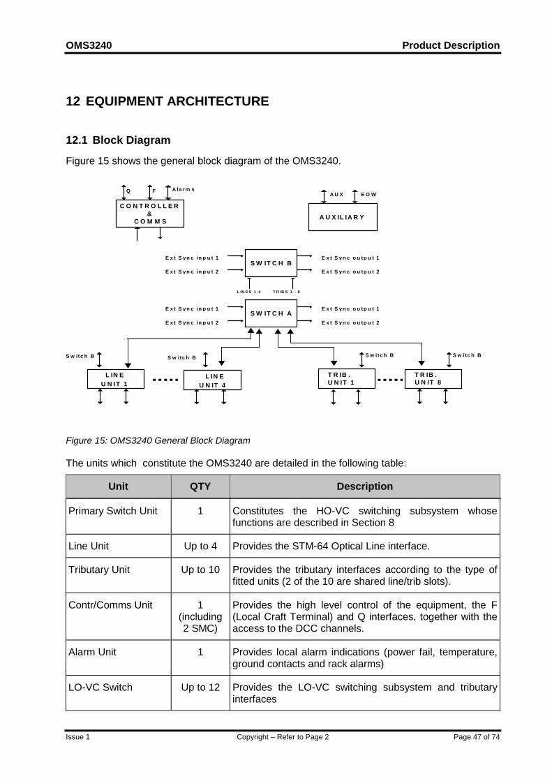
OMS3240 Product Description
Issue 1 Copyright – Refer to Page 2 Page 47 of 74
12 EQUIPMENT ARCHITECTURE
12.1 Block Diagram
Figure 15 shows the general block diagram of the OMS3240.
E x t S yn c o u tp u t 1
E x t S yn c o u tp u t 2
L IN E S 1 -4 T R IB S 1 - 8
C O N T R O L L E R&
C O M M S A U X IL IA R Y
Q F E O WA U X
S W IT C H B
S W IT C H A
E x t S yn c in p u t 1
E x t S yn c in p u t 2
S w itc h B S w itc h B S w itc h B
U N IT 8
S w itc h B
E x t S yn c in p u t 2
E x t S yn c in p u t 1
U N IT 1T R IB . T R IB .L IN E
U N IT 1L IN E
U N IT 4
E x t S yn c o u tp u t 1
E x t S yn c o u tp u t 2
A la rm s
Figure 15: OMS3240 General Block Diagram
The units which constitute the OMS3240 are detailed in the following table:
Unit QTY Description
Primary Switch Unit 1 Constitutes the HO-VC switching subsystem whosefunctions are described in Section 8
Line Unit Up to 4 Provides the STM-64 Optical Line interface.
Tributary Unit Up to 10 Provides the tributary interfaces according to the type offitted units (2 of the 10 are shared line/trib slots).
Contr/Comms Unit 1(including2 SMC)
Provides the high level control of the equipment, the F(Local Craft Terminal) and Q interfaces, together with theaccess to the DCC channels.
Alarm Unit 1 Provides local alarm indications (power fail, temperature,ground contacts and rack alarms)
LO-VC Switch Up to 12 Provides the LO-VC switching subsystem and tributaryinterfaces
Product Description OMS3240
Page 48 of 74 Copyright – Refer to Page 2 Issue 1
LTU PSU 2 Provides derived voltage to the LTUs (also providesV.11/G.703 Auxiliary interfaces)
Battery LTU 2 Provides filtered subrack feed voltage to the cards LTUPSUs and fans.
Management LTU 1 Provides physical connectors for Q interface, F interface,and extension subrack (also provides EOW interface)
Sync LTU 1 Provides external synchronisation input and outputinterfaces (also provides Ground contact and rack alarminterfaces)
Fan tray unit 5 Maintains correct environmental temperature
Optional units
Primary Switch Unit 1 Provides protection.
Contr/Comms Unit 1 (including2 SMC)
Provides protection.
Auxiliary Unit 1 Provides communication channels for service functions
12.1.1 Line Units
In OMS3240, these are single port STM-64 units that are either single slot width grey orcoloured. They perform the following functions:
• optical interface;
• SOH insertion/extraction;
• AU-4 mapping/demapping;
• VC-4 POH supervision; this function can be activated/deactivated by the user;
• selection of one of the two data streams received from the matrices by means ofinsertion/monitoring of check messages.
12.1.2 Tributary Units
In OMS3240, the tributary units perform the following functions:
• optical/electrical interface;
• SOH insertion/extraction;
• AU-4 mapping/demapping;
• VC-4 POH supervision; this function can be activated/deactivated by the user;
• selection of one of the two data streams received from the switch by means ofinsertion/monitoring of check messages.
OMS3240 Product Description
Issue 1 Copyright – Refer to Page 2 Page 49 of 74
In order to guarantee a high level of availability the Electrical Tributary Unit can be cardprotected.
The card protection schemes are:
• two groups of electrical tributary cards can be 1:N protected, with N up to 4.
• 1:N card protection is REVERTIVE.
and are based on the following switching criteria:
• internal failure of the working unit;
• extraction of a working unit.
12.1.3 OTN Tributary/Line Units
In OMS3240, these units perform the following functions:
• Optical interface;
• OTU/ODU/OPU Overhead management
• OTU sink/source termination;
• ODU/OPU sink/source termination for Client Signal extraction or ODU multiplexing;
• CBR Client Signal mapping/demapping
• SOH on SDH Client Signal insertion/extraction;
• AU-4 mapping/demapping;
• VC-4 POH supervision; this function can be activated/deactivated by the user;
• selection of one of the two data streams received from the switch by means ofinsertion/monitoring of check messages.
12.1.4 HO Switch Unit
In OMS3240, this unit performs the following functions:
• cross connection at ODU1, ODU2, VC-4 and VC-4-Xc level;
• equipment timing;
• multiplex section protection (MSP);
• MS-SPRing protection;
• Sub-Network Connection Protection;
In order to guarantee a high level of availability the Switch Unit can be 1+1 protected.
Product Description OMS3240
Page 50 of 74 Copyright – Refer to Page 2 Issue 1
Switch fault detection is achieved through the insertion of check messages performed by theinput working traffic card into traffic entering the switch (devoted bytes of the proprietary internalframe). The monitoring of the messages in the traffic leaving the switch is performed by theoutput working traffic card. Checking consists of:
• comparison between source port contained in the message and the expected one
• parity checks.
During normal working conditions the traffic is transmitted to both switches. In case of fault, thereceiving traffic card selects the traffic from the error-free switch, raises an alarm and theController then disables the faulty switch.
The changeover between the two units is hitless.
12.1.5 LO-VC Switch Unit
In OMS3240, this unit performs the following functions:
• cross connection at VC-4/3/2/12 level;
• multiplex section protection (MSP);
• Sub-Network Connection Protection;
• SDH cross connection at VC-4/3/2/12 level;
• SOH and POH processing of the on-board STM-n interfaces;
• POH processing of the LO-VC received from the HO-VC switching subsystem;
In order to guarantee a high level of availability the Switch Unit can be 1+1 protected.
Switch fault detection is achieved through the check of diagnostic messages.
During normal working conditions the traffic is transmitted to both switches. In case of fault, thereceiving traffic card selects the traffic from the error-free switch, raises an alarm and theController then disables the faulty switch.
12.1.6 Communication/Controller Unit
This unit supports the high-level control of the equipment as defined by G.783, the F and Qinterfaces together with the access to the DCC/GCC channels as requested by G.784 andG798. The Communication/Controller unit contains, in its not-volatile memory, the Softwareexecutables of the cards on the subrack and all the equipment configuration data.Auxiliary Unit
12.1.7 Auxiliary Unit
This unit implements the OHA logical block according to G.783.
12.2 Internal Distribution Of Signals
The internal signals can be subdivided in:
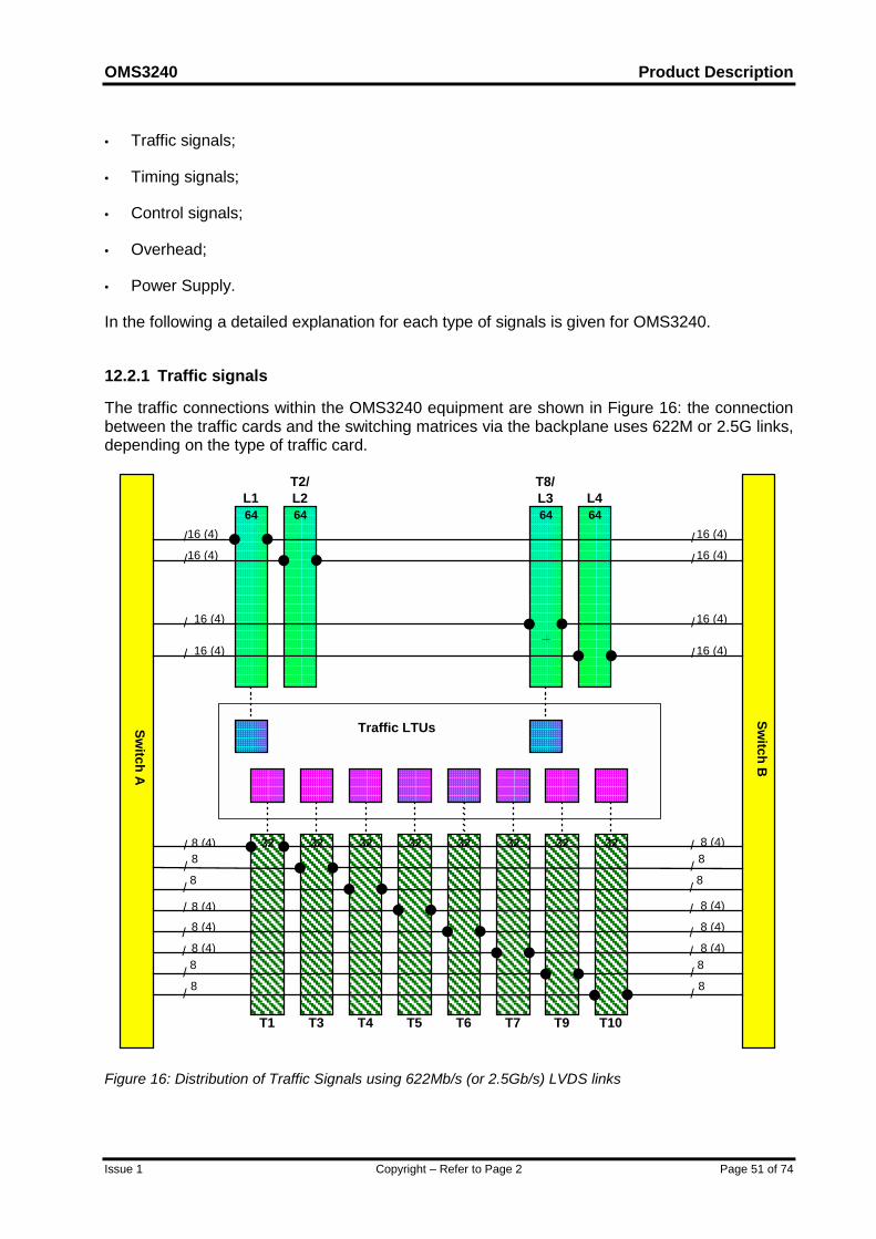
OMS3240 Product Description
Issue 1 Copyright – Refer to Page 2 Page 51 of 74
• Traffic signals;
• Timing signals;
• Control signals;
• Overhead;
• Power Supply.
In the following a detailed explanation for each type of signals is given for OMS3240.
12.2.1 Traffic signals
The traffic connections within the OMS3240 equipment are shown in Figure 16: the connectionbetween the traffic cards and the switching matrices via the backplane uses 622M or 2.5G links,depending on the type of traffic card.
Switch A
Switch B
64L1
T2/L2
T5T1 T4T3 T6 T7 T9 T10
64
32 32 32 32 32 32 32 32
L464
Traffic LTUs
T8/L364
/
/
/
16 (4)/
/
/
//
8 (4)/8/
// 8
/8/
// 8
// 8
8
//
// 8
8
//
16 (4)
16 (4)
16 (4)
16 (4)
16 (4)
16 (4)
16 (4)
8 (4)
8 (4)
8 (4)
8 (4)
8 (4)
8 (4)
8 (4)
Figure 16: Distribution of Traffic Signals using 622Mb/s (or 2.5Gb/s) LVDS links
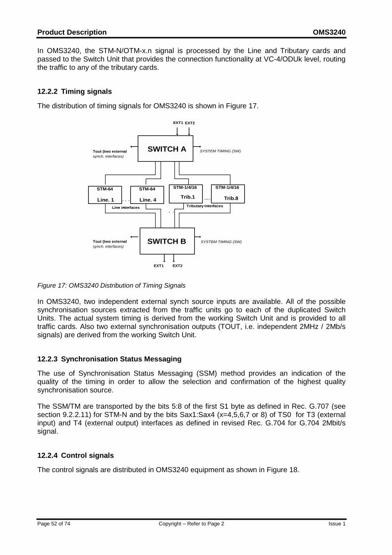
Product Description OMS3240
Page 52 of 74 Copyright – Refer to Page 2 Issue 1
In OMS3240, the STM-N/OTM-x.n signal is processed by the Line and Tributary cards andpassed to the Switch Unit that provides the connection functionality at VC-4/ODUk level, routingthe traffic to any of the tributary cards.
12.2.2 Timing signals
The distribution of timing signals for OMS3240 is shown in Figure 17.
EXT1 EXT2
SYSTEM TIMING (SW)Tout (two externalsynch. interfaces)
Tout (two externalsynch. interfaces)
. .
. ..……. .. . Tributary interfaces
Trib.1
STM-1/4/16
Trib.8
STM-1/4/16
Line. 4. . . .. . .Line interfaces
STM-64
Line. 1
STM-64
SWITCH A
SYSTEM TIMING (SW)
EXT1 EXT2
SWITCH B
Figure 17: OMS3240 Distribution of Timing Signals
In OMS3240, two independent external synch source inputs are available. All of the possiblesynchronisation sources extracted from the traffic units go to each of the duplicated SwitchUnits. The actual system timing is derived from the working Switch Unit and is provided to alltraffic cards. Also two external synchronisation outputs (TOUT, i.e. independent 2MHz / 2Mb/ssignals) are derived from the working Switch Unit.
12.2.3 Synchronisation Status Messaging
The use of Synchronisation Status Messaging (SSM) method provides an indication of thequality of the timing in order to allow the selection and confirmation of the highest qualitysynchronisation source.
The SSM/TM are transported by the bits 5:8 of the first S1 byte as defined in Rec. G.707 (seesection 9.2.2.11) for STM-N and by the bits Sax1:Sax4 (x=4,5,6,7 or 8) of TS0 for T3 (externalinput) and T4 (external output) interfaces as defined in revised Rec. G.704 for G.704 2Mbit/ssignal.
12.2.4 Control signals
The control signals are distributed in OMS3240 equipment as shown in Figure 18.
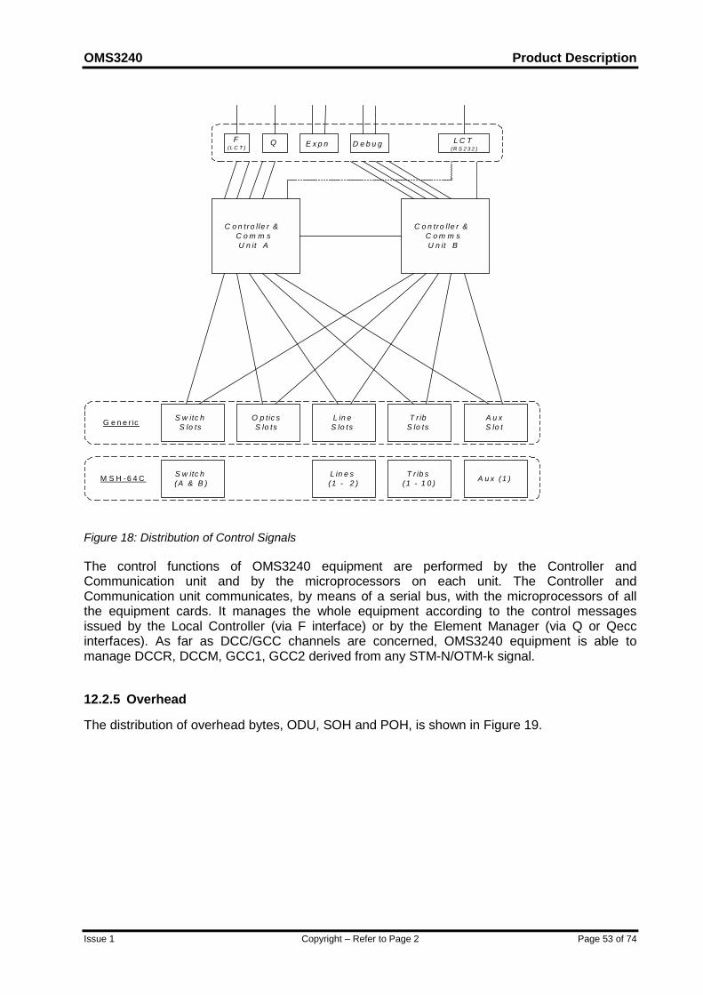
OMS3240 Product Description
Issue 1 Copyright – Refer to Page 2 Page 53 of 74
C o n tro lle r &C o m m sU n it A
C o n tro lle r &C o m m sU n it B
L C T(R S 2 3 2 )
F(L C T )
Q E x p n D e b u g
T r ibS lo ts
S w itc hS lo ts
L in eS lo ts
O p tic sS lo ts
A u xS lo t
T r ib s(1 - 1 0 )
S w itc h(A & B )
L in e s(1 - 2 ) A u x (1 )M S H -6 4 C
G e n e r ic
Figure 18: Distribution of Control Signals
The control functions of OMS3240 equipment are performed by the Controller andCommunication unit and by the microprocessors on each unit. The Controller andCommunication unit communicates, by means of a serial bus, with the microprocessors of allthe equipment cards. It manages the whole equipment according to the control messagesissued by the Local Controller (via F interface) or by the Element Manager (via Q or Qeccinterfaces). As far as DCC/GCC channels are concerned, OMS3240 equipment is able tomanage DCCR, DCCM, GCC1, GCC2 derived from any STM-N/OTM-k signal.
12.2.5 Overhead
The distribution of overhead bytes, ODU, SOH and POH, is shown in Figure 19.
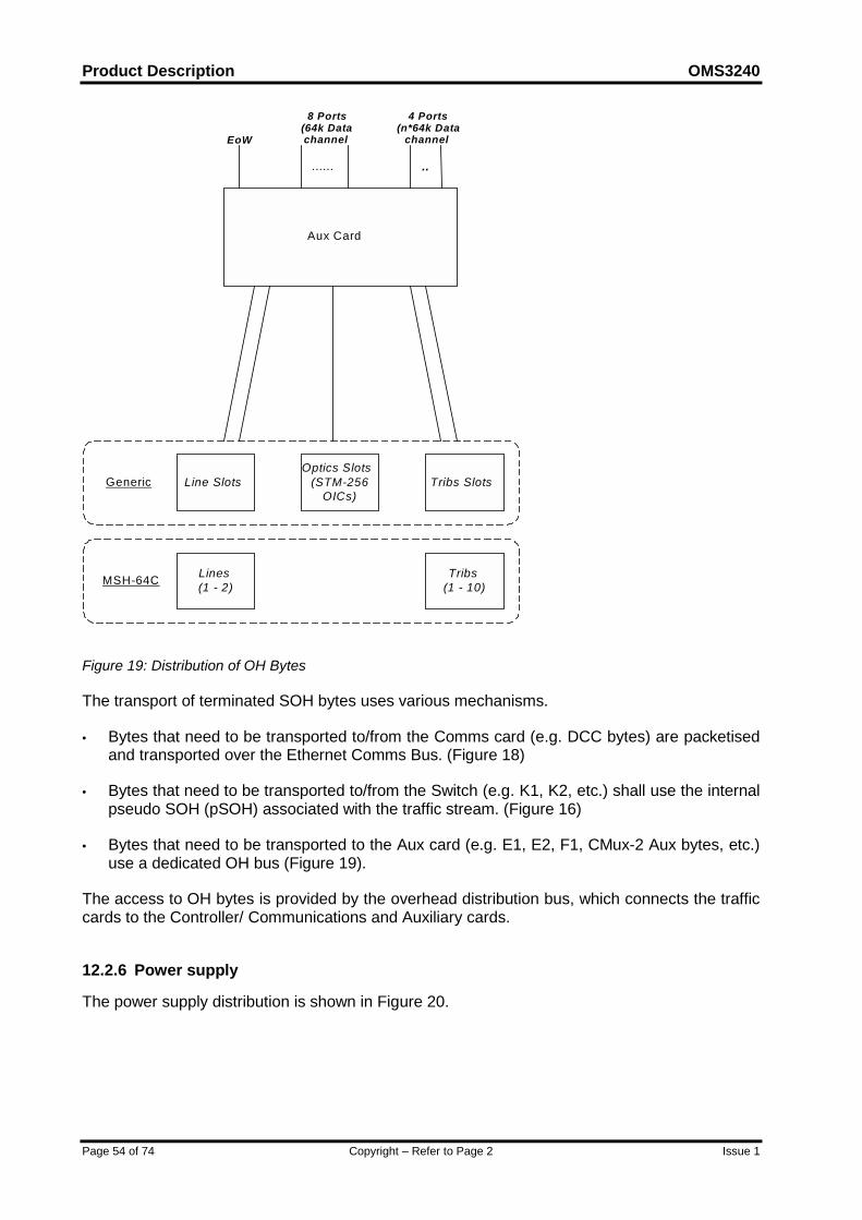
Product Description OMS3240
Page 54 of 74 Copyright – Refer to Page 2 Issue 1
Aux Card
EoW
..
4 Ports(n*64k Data
channel)
......
8 Ports(64k Datachannel)
Tribs SlotsLine SlotsOptics Slots
(STM-256OICs)
Generic
MSH-64C Tribs(1 - 10)
Lines(1 - 2)
Figure 19: Distribution of OH Bytes
The transport of terminated SOH bytes uses various mechanisms.
• Bytes that need to be transported to/from the Comms card (e.g. DCC bytes) are packetisedand transported over the Ethernet Comms Bus. (Figure 18)
• Bytes that need to be transported to/from the Switch (e.g. K1, K2, etc.) shall use the internalpseudo SOH (pSOH) associated with the traffic stream. (Figure 16)
• Bytes that need to be transported to the Aux card (e.g. E1, E2, F1, CMux-2 Aux bytes, etc.)use a dedicated OH bus (Figure 19).
The access to OH bytes is provided by the overhead distribution bus, which connects the trafficcards to the Controller/ Communications and Auxiliary cards.
12.2.6 Power supply
The power supply distribution is shown in Figure 20.
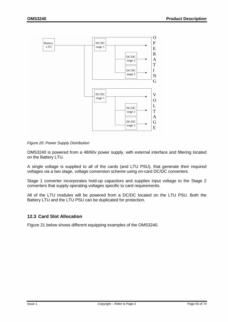
OMS3240 Product Description
Issue 1 Copyright – Refer to Page 2 Page 55 of 74
DC/DCstage 1
DC/DCstage 2
DC/DCstage 2
Battery LTU
DC/DCstage 1
DC/DCstage 2
DC/DCstage 2
OPERATING
VOLTAGE
Figure 20: Power Supply Distribution
OMS3240 is powered from a 48/60v power supply, with external interface and filtering locatedon the Battery LTU.
A single voltage is supplied to all of the cards (and LTU PSU), that generate their requiredvoltages via a two stage, voltage conversion scheme using on-card DC/DC converters.
Stage 1 converter incorporates hold-up capacitors and supplies input voltage to the Stage 2converters that supply operating voltages specific to card requirements.
All of the LTU modules will be powered from a DC/DC located on the LTU PSU. Both theBattery LTU and the LTU PSU can be duplicated for protection.
12.3 Card Slot Allocation
Figure 21 below shows different equipping examples of the OMS3240.
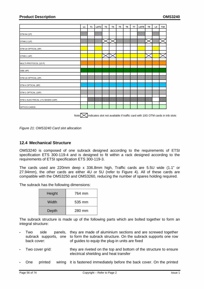
Product Description OMS3240
Page 56 of 74 Copyright – Refer to Page 2 Issue 1
L1 T1 L2/T2 T3 T4 T5 T6 T7 L3/T8 T9 L4 T10
STM-64 (1P)
OTM0.2 (1P)
STM-16 OPTICAL (4P)
OTM0.1 (4P)
MULTI-PROTOCOL (10 P)
GBE (4P)
STM-16 OPTICAL (2P)
STM-4 OPTICAL (8P)
STM-1 OPTICAL (16P)
STM-1 ELECTRICAL LTU BASED (16P)
OPTICS CARDS
Note indicates slot not available if traffic card with 10G OTM cards in trib slots
Figure 21: OMS3240 Card slot allocation
12.4 Mechanical Structure
OMS3240 is composed of one subrack designed according to the requirements of ETSIspecification ETS 300-119-4 and is designed to fit within a rack designed according to therequirements of ETSI specification ETS 300-119-3.
The cards used are 220mm deep x 336.8mm high, Traffic cards are 5.5U wide (1.1” or27.94mm), the other cards are either 4U or 5U (refer to Figure 4). All of these cards arecompatible with the OMS3250 and OMS3260, reducing the number of spares holding required.
The subrack has the following dimensions:
Height 764 mm
Width 535 mm
Depth 280 mm
The subrack structure is made up of the following parts which are bolted together to form anintegral structure:
• Two side panels,subrack supports, oneback cover:
they are made of aluminium sections and are screwed togetherto form the subrack structure. On the subrack supports one rowof guides to equip the plug-in units are fixed
• Two cover grid: they are riveted on the top and bottom of the structure to ensureelectrical shielding and heat transfer
• One printed wiring it is fastened immediately before the back cover. On the printed

OMS3240 Product Description
Issue 1 Copyright – Refer to Page 2 Page 57 of 74
board (i.e. back panel): wiring board rows of connectors are fitted: the bottom rowscomprise all the connectors for the plug-in units, the top row, allthe connectors for the termination unit of the electrical interfacesoptical fibre management: for running the optical fibres to theSTM-N optical units
• Environmental ControlDevice:
It is equipped to assist the thermal management of thesubrack
Each subrack is designed to fit within a rack, designed according to the requirements of ETSIspecification ETS 300-119-3. The rack has the following dimensions:
• Height 2200 mm;
• Width 600 mm; (900mm with fibre ducts)
• Depth 300 mm.
The equipment can also be housed in racks with different height (e.g. 2600 mm).
The rack can be accessed only from the front. It is made up of several mechanical parts whichare bolted together to form an integral structure:
One top/base element: they are bolted to the vertical supports and consist of analuminium section, varnished on the outer surface. They havethree wide opening, one central and two side opening both usedfor exchange cable entry (if not used on the three openings a gridis fitted). On the base element four footed, screws that ca beadjusted to compensate for any floor unevenness of up to 25 mm
Four vertical support: they are fastened to the inside corners to provide further strengthfor the rack. The two front vertical support bear 82 square holes(6.5 mm, spaced 25), for fixing the equipment subracks. All foursupports also bear holes (4 mm) for fixing last item below
Two side panels and onerear panel:
they are bolted together
Two fibre ducts: these are 150mm wide and are bolted on to either side of the rackto house the optical fibre
Rack alarm unit it is assembled in a compartment at the front of the top element.The unit provides visual rack alarms and rack alarm re-transmission capabilities (by means of ground-contacts)
Power Distribution Panel(optionally):
it can be fixed in the rack to provide termination and distribution ofseparate power supply courses for each equipment in the rack.
At the top of the right vertical support is located the rack ground lug. All the four verticalsupports, the base element and the top element are electrically connected to ensure groundcontinuity.
Product Description OMS3240
Page 58 of 74 Copyright – Refer to Page 2 Issue 1
It is possible to locate the racks either back-to-back (double row), back to wall or side by side(single row).
12.5 Connectors
All interface connectors are available from the front of the equipment.
12.5.1 Optical Traffic Connectors
The optical standard connectors are:
• LC type for STM-1, Gigabit Ethernet and all the SFP modules
• SC type for non-SFP STM-4/16/64 and OTNm.n.
The optical cables are routed directly to the front of the optical units, where the opticalconnectors are located.
12.5.2 Electrical Traffic Connectors
The standard electrical interfaces are available with the following range of connectors:
• 1.0/2.3 mm 75 ohm (for 155 Mbit/s interfaces)
• Sub-D connector for 120 ohm 2Mbit/s interfaces
• RJ-45 for GbE and FE interfaces.
12.5.3 Other Connectors
2 Mbit/s or 2 MHz Synch. input 1.0/2.3 mm 75ohm /120 ohm symm. pair
2 MHz / 2 Mb/s Synch. output 1.0/2.3 mm 75 ohm /120 ohm symm. pair
Q interface The following types may be made available:
• Sub-D 15 pins (ISO 4903), for ISO 802.3 10base5 (ThickEthernet)
• BNC, for ISO 802.3 10base2 (Thin Ethernet)
• RJ45 for 10baseT
F interface Sub-D 9 pins (ISO 4902)
Power Supply Due to the high current requirements the battery cables(25mm sq. cable with M8 crimp terminal) are bolted to theBattery LTU;
Alarms (Rack summary) Sub-D 9 pins (ISO 4902)
OMS3240 Product Description
Issue 1 Copyright – Refer to Page 2 Page 59 of 74
Alarms (ground contacts) Sub-D 37 pins (ISO 4902)
Auxiliary data channels 64 kb/s, G.703 Sub-D 25 pins (ISO 2110), 64
kb/s, V.11 Sub-D9 pins (ISO 4902)
EOW Bantham Jack
EOW extension Sub-D 9 pins (ISO 4902)
12.6 Cables
Following types of cables are used to connect the equipment with external devices (e.g., DDF,ODF):
• pair cable with separate shielding of each pair
• pair cable with shielding of several pairs
• co-axial cables (3002 co-ax cable (NOM O/D 3.5mm)6)
• optical cable (maximum O/D 2.5mm1)
• DC-power cable
The design of fibre management areas is such as to let access to individual fibre circuits forsplicing, connectorising, removal or re-routing without affecting working fibres.
6 These are recommended in order to support a fully fibred system

Product Description OMS3240
Page 60 of 74 Copyright – Refer to Page 2 Issue 1
13 ALARMSAlarms raised by OMS3240 and the related processing are based on ITU-T G.783, G.784 andG.798 requirements.
13.1 Unit Alarm Displays
Individual, on unit, unit failure indication is provided.
Each unit in the shelf contains at least two LEDs on the front:
• LED 1: RED
This LED indicates the unit fault condition.
It is local alarm scheme dependant, for example:
- with MSH alarm scheme, the Red fault LED is lit on the equipment card, if the fault is acategory INT fault.
- with Bw7R if a Red fault LED is lit on an equipment card, it indicates a fault on the actualequipment card (possibly requiring change of equipment card).
- with TEP1E if a Red fault LED is lit on an equipment card, it indicates a traffic orequipment fault.
• LED 2: GREEN
This LED indicates the currently operating units. Therefore it is normally active on the unitswhen they have:
- Correct internal power levels;
- Microprocessor in operation (if applicable).
A means of testing the LEDs is provided.
13.2 Rack Alarm Displays
The rack alarm indications are:
• RED Lamp (summary urgent alarm);
• GREEN Lamp (summary not-urgent alarm);
• YELLOW Lamp (reminder indication);
• General Rack Alarm (summary alarm and reminder) ground contacts;
The management of these lamps is performed according to the selected alarm scheme.

OMS3240 Product Description
Issue 1 Copyright – Refer to Page 2 Page 61 of 74
13.3 Alarm Processing
Alarms from each unit are collected and processed by the Communications/Controller unit,which performs the following functions:
• alarm inhibition;
• assignment of a category (e.g. urgent, not-urgent) to each alarm;
• alarm reduction (in case an alarm occurs for a specific transport layer, the consequentialalarms on the transported streams are removed);
• alarm filtering, logging and reporting: capability to select the alarm destination (to ElementManager and/or to the local alarm log and/or to the local terminal - the operator will beinformed that an alarm exists);
• ground contacts driving;
• rack alarm interface driving.
All above-mentioned alarm processing functions can be configured via Element Manager orLocal Terminal.
A cyclic local alarm log is available within the equipment. It is able to store al least 200 alarmmessages.
Alarms can be either indicated through lamps/ground contacts, or sent to the local terminal or tothe Element Manager.
Alarm outputs can be customised using the Local Terminal or from the OAM&P, an examplescheme of indications and functions that are provided by the Communications/Controller unit isas follows:
• Any alarm indication ("ANY") RED
• Reminder indication ("MEM") YELLOW
• Urgent alarm indication ("URG") RED
• Not urgent alarm indication ("NURG") RED
• Internal alarm indication (“INT”) RED
• External alarm indication ("EXT") RED
• Indicative alarm ("IND")(for alarms such as RDI and AIS) YELLOW
• Indication of abnormal condition (“ABN”) YELLOW
• Local receive attention push button
• Lamp test push button
Input and Outputs Ground contacts are also available.

Product Description OMS3240
Page 62 of 74 Copyright – Refer to Page 2 Issue 1
The power fail (or out of range) takes top priority and it is present even in the absence ofCommunications/Controller Unit.
Different solutions can be implemented, depending on the requirements of the Operator.

OMS3240 Product Description
Issue 1 Copyright – Refer to Page 2 Page 63 of 74
14 PERFORMANCE MONITORING AND MANAGEMENTThe transmission quality on tributary interfaces is monitored in accordance with ITU-T G.784and G. 828.
The monitoring of performance parameters is based on the evaluation of errored blocks (EB).The parameters that are related to the performance monitoring are provided in the following:
• BBE (Background Block Error)
• ES (Errored Second)
• SES (Severely Errored Second)
• OFS (Out of Frame Second);
Furthermore the following additional parameters can be optionally monitored:
• CSES (Consecutive SES)
• UAS (Unavailable Seconds)
• AU PJE (Negative/Positive Administrative Unit Pointer Justification Events).
All these parameters are evaluated and stored, during available time, in 15 min. and 24 h.registers according to G.784 requirements.
Such performance data is available to the System Manager (operator) (see EquipmentManagement).
14.1 OTN performance monitoring
As required by ITU-T G.798 and ITU-T draft recommendation G.optperf, performanceMonitoring can be carried out at the following layers of a signal transported in an OTN network:
• Ochr to OTUk Adaptation layer (Performance on Forward Error Correction)
The number of corrected bits are counted over 1 second and reported to the managementsystem at the end of the second, unless TSF, dAIS, dLOM or dLOF are present.
• OTUk Termination based on SM overhead bytes information
Performance on OTUk Termination is specifically created to enable the monitoring of theperformance of an end-to-end OTUk trail. Both Near End and Far End performancemonitoring can be enabled. For both directions the following parameters can be collected:ES, SES, BBE, UAS, CSES, IAE (one second period in which at least one dIAE defect isdetected).
• ODUkP Termination or Monitoring based on PM overhead bytes information
Performance on ODUkP Termination (Monitoring) is specifically created to enable themonitoring of the performance of an end-to-end (or part of an) ODUk path. Both Near End

Product Description OMS3240
Page 64 of 74 Copyright – Refer to Page 2 Issue 1
and Far End performance monitoring can be enabled. For both directions the followingparameters can be collected: ES, SES, BBE, UAS, CSES.
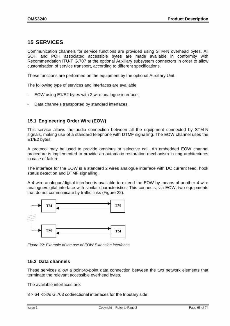
OMS3240 Product Description
Issue 1 Copyright – Refer to Page 2 Page 65 of 74
15 SERVICESCommunication channels for service functions are provided using STM-N overhead bytes. AllSOH and POH associated accessible bytes are made available in conformity withRecommendation ITU-T G.707 at the optional Auxiliary subsystem connectors in order to allowcustomisation of service transport, according to different specifications.
These functions are performed on the equipment by the optional Auxiliary Unit.
The following type of services and interfaces are available:
• EOW using E1/E2 bytes with 2 wire analogue interface;
• Data channels transported by standard interfaces.
15.1 Engineering Order Wire (EOW)
This service allows the audio connection between all the equipment connected by STM-Nsignals, making use of a standard telephone with DTMF signalling. The EOW channel uses theE1/E2 bytes.
A protocol may be used to provide omnibus or selective call. An embedded EOW channelprocedure is implemented to provide an automatic restoration mechanism in ring architecturesin case of failure.
The interface for the EOW is a standard 2 wires analogue interface with DC current feed, hookstatus detection and DTMF signalling.
A 4 wire analogue/digital interface is available to extend the EOW by means of another 4 wireanalogue/digital interface with similar characteristics. This connects, via EOW, two equipmentsthat do not communicate by traffic links (Figure 22).
TM
TM
TM
TM
Figure 22: Example of the use of EOW Extension interfaces
15.2 Data channels
These services allow a point-to-point data connection between the two network elements thatterminate the relevant accessible overhead bytes.
The available interfaces are:
8 × 64 Kbit/s G.703 codirectional interfaces for the tributary side;

Product Description OMS3240
Page 66 of 74 Copyright – Refer to Page 2 Issue 1
4 × (N×64) Kbit/s V.11 contradirectional interfaces for the line side7;
7 n can be 1,3,9; 3 or 9 in order to transport either DCCR or DCCM
OMS3240 Product Description
Issue 1 Copyright – Refer to Page 2 Page 67 of 74
16 GENERAL OPERATING FEATURESThe equipment assists the operators in a lot of common tasks, defined as general operatingfeatures, related with:
• equipment use;
• plug-in unit handling;
• fault maintenance (self diagnostic);
• recovery from faults;
• equipment robustness;
• inventory.
16.1 Equipment Use
The equipment supports the operator during installation and provides useful facilities likemanual restart, software and hardware consistency check, the possibility of upgrading systemfunctionality without disturbing the traffic.
16.2 Plug-in Unit Handling
Replacement of one plug-in unit with one of the same type does not require any reconfigurationon any of the other units on the shelf while the newly inserted unit is automatically configured asthe extracted one.
Removal and insertion of the units are reported to the management system.
16.3 Fault Management (Self Diagnostic)
Built-in diagnostic facilities identify the single unit that needs changing or the faulty interface, forall faults occurring within the equipment or detectable at its interface.
This operation is carried out automatically using non-intrusive monitoring inside the networkelement.
Management and operation of the diagnostic facilities are available both from a remote locationand from local operation. The equipment is capable of:
• automatically transferring an alarm report with data about the failure to a remotemanagement centre immediately on detection of a failure;
• automatically switching on fault the functionality to the protection units, if duplicated units arefitted.

Product Description OMS3240
Page 68 of 74 Copyright – Refer to Page 2 Issue 1
16.4 Recovery From Faults
A failure in the control unit does not cause traffic outage or affect the operation of networkprotection. The control unit contains and updates a complete and accurate ManagementInformation Base that corresponds to the hardware state of the equipment.
16.5 Equipment Robustness
The equipment is designed in order to protect the system data against unintentionalmodifications and to avoid faults or configuration changes occurring in limited portions of thesystem causing any functional degradation in the remaining parts of it.
16.6 Inventory
The equipment maintains a record of all its component units. Each equipment is modelled as acollection of managed objects as detailed in ITU-T Rec. G.774 SDH Information Model.
The equipment performs the following features:
• the Electronic Inventory Data is automatically updated; at all times it is the current record ofall the parts forming the equipment;
• all inventory information held by the equipment are accessible by the LCT and NMS;
• physical details (e.g. code, serial number, version) of all the hardware and software partswhich form the equipment are stored.
• the storage of inventory data within the equipment is non-volatile;
• all inventory information relating to a network element can be accessed remotely.

OMS3240 Product Description
Issue 1 Copyright – Refer to Page 2 Page 69 of 74
17 EQUIPMENT MANAGEMENTOMS3240 can be monitored and controlled through:
• F interface: to a local terminal;
• Q interface: to ServiceOn™ Optical Element Manager; the provided interface is type CLNS1(Ethernet), The new generation SDH/OTH equipment (OMS3240, OMS3250 and OMS3260)implement a standard based Q3 agent, but only the first four layers of the communicationstack will be used to carry the management information with sensible improvements in thebandwidth usage. This proprietary implementation, namely CMOX, exploits the capability tocarry the CMISE over the transport layer directly.
• Qecc (from line or tributary SDH interface): as defined by ITU-T/ G.784.
• GMPLS: the control plane on OMS3240 is able to support GMPLS functionality.
The provided OAM&P functions are in accordance with ITU-T/G.784. In particular it is possibleto perform:
• configuration management:
• provisioning (configuration of all equipment characteristics, e.g. internal channel routing);
• protection switching management;
• installation;
• fault (maintenance) management:
• alarm surveillance (collection, filtering, reporting);
• testing (equipment and connections);
• performance management:
• performance data collection;
• performance data reporting;
• general functions (e.g. security, software download).
• performance data reporting;
The equipment supports the ITU-T/ETSI standard information model.
More precisely, OMS3240 is designed to support the information model based on:
• ITU-T Recommendations M.3100, G.774;
• ETSI ETS 300 304, ETS 300 371.

Product Description OMS3240
Page 70 of 74 Copyright – Refer to Page 2 Issue 1
The OMS3240 can be managed by a computer system dedicated to the administration ofSDH/OTH equipment and allows functionality that deal with the data to be modifiable by theOperations System.
The main features of these functions are the following:
• equipment configuration is set and notified at card level and software download and versioncontrol is offered on all cards;
• Protection Switching Feature, line protection, path protection and card protection can beconfigured and notified to the management, to meet the service availability target;
• Performance monitoring is carried out continuously by the equipment: it allows evaluation ofthe quality of the links both at section and path level and gives an indication in advance ofpotential degradation of the service.
Physically, OMS3240 is managed through an Ethernet Local Area Network. Bridge/routers areused to provide interworking between the LAN and Wide Area Networks (Leased Lines). TheWAN shall be connected when the equipment is remotely located. If the equipment is close tothe Operations System, there is no need of routers and WAN connections.

OMS3240 Product Description
Issue 1 Copyright – Refer to Page 2 Page 71 of 74
18 TECHNICAL SPECIFICATIONS
18.1 Electrical Environment
The equipment is in compliance with: .................. EEC Council Directive 89/336/EEC;
.............. ETS 300 386-2 (EMC/EMI/ESD).
The requirements are met by the subrack alone and do not rely on any features of the rack.
18.2 Climatic and Mechanical Environment
18.2.1 General
The minimal classes of environmental conditions, their severity and general definitions arespecified according to ETSI ETS 300-019-1-0.
18.2.2 Storage Endurance
Storage endurance minimal requirements are according to ETSI ETS 300 019-1-1, Class 1.2,"Not temperature controlled storage locations".
The climatic environmental limits for normal storage conditions are:
• Temperature: from -25 to 55°C;
• Relative humidity: from 10% to 100%.
18.2.3 Transport Endurance
Transport endurance minimal requirements are according to ETSI ETS 300 019-1-2, Class 2.3,"Public Transportation".
The climatic environmental limits for normal transport conditions are:
• Temperature: from -40 to 70 °C;
• Relative humidity: up to 95%.
18.2.4 Environmental Endurance For Indoor Operation
Weather-protected stationary use endurance minimal requirements are according to ETSI ETS300 019-1-3, Class 3.2, "Partly temperature controlled locations".
The climatic environmental limits for normal operating conditions are:
• Temperature: from -5 to 45 °C;

Product Description OMS3240
Page 72 of 74 Copyright – Refer to Page 2 Issue 1
• Relative humidity: from 5% to 95%.
18.3 System Performance
18.3.1 Error Performance
The general error performance is that no errors are introduced into traffic by the equipmentunder the most adverse environmental and operational conditions specified.
18.3.2 Transmission Delay
The delay times for a transmission signal from its input to its output for multiplexing functions is ≤ 125 µs
18.3.3 Jitter Characteristics
According to:
Input jitter and wander tolerance……………ITU-T/ G. 823, 824, 825 requirements;
Maximum output jitter and wander…………ITU-T/ G. 783 requirements;
Jitter and wander transfer………………… ITU-T/ G. 783, 958 requirements.
18.4 Power Requirements (according to ETSI ETS 300-132)
The equipment operates without pre-setting in the range -38.4 to -72 V, suitable for the batteryvoltages (supplied by two separate fuse protected and diode connected parallel lines).
Supply voltages: …………………-48V +/- 20%
…………………-60V +/- 20%
The power supply from Vac mains (duplicated) is also possible by using external AC/DCconverters suitable for rack mounting and located on a different shelf.
The earthing is in accordance with ETSI standard ETS 300 253.
18.5 Synchronisation
Synchronisation sources available:
Independent external reference input. Either:
• 2 MHz G.703-13
• 2 Mb/s framed G.703-9, G.706
• 2 Mb/s unframed G.703-9);
• Recovered line timing via STM-N line Units;
OMS3240 Product Description
Issue 1 Copyright – Refer to Page 2 Page 73 of 74
• Recovered tributary timing derived STM-N tributary interface;
• Internal oscillator on the Switch Unit (stability better than 4.6 ppm. acc. to G.813).
Two independent synchronisation outputs are available.
Either:
• 2 MHz G.703-13
• 2 Mb/s framed G.703-9, G.706 with SSM
• 2 Mb/s framed G.703-9, G.706 w/o SSM
18.6 Power Consumption
Power consumption from the battery:
Example OMS3240 configs:
4xSTM-64, 8xSTM-16 (2p) approx. 0.7 kW
4xSTM-64, 8xSTM-4 (8p) approx. 0.9 kW
4xSTM-64, 8xSTM-1 (16p) approx. 0.8 kW
2xSTM-64, 10xSTM-16 (2p/4p) approx. 0.7 kW
2xSTM-64, 10xSTM-4 (8p) approx. 0.9 kW
2xSTM-64, 10xSTM-1 (16p) approx. 0.7 kW
18.7 Safety
18.7.1 General
The equipment is designed not to cause any harm or danger to personnel installing, maintainingor operating the equipment, and not to produce any damage to the network or other equipmentconnected to it.
The equipment complies with the following safety standards:
• EN 60950 (for information technology equipment)
• EN 41003 (for equipment to be connected to telecommunication network)
• IEC 364 (for electrical installations of buildings)
• IEC 825 (for laser products)

Product Description OMS3240
Page 74 of 74 Copyright – Refer to Page 2 Issue 1
18.7.2 Optical safety requirements
The automatic laser shutdown function complies with ITU-T G.958/G.664.
End of Document