
27 September 2002 Bobby Nazief ([email protected]) Johny Moningka ([email protected])
Upload
victoria-eatonCategory
view
239download
2
2 Fakultas Ilmu Komputer UI
True/falseTrue/false
Keys are always unique A row can be uniquely identified by a keyThe functional dependency noted as A B, means that the value of A can be determined from the value of B. A characteristic of a relation is that the cells of the relation hold a single value A tuple is a group of one or more columns that uniquely identifies a row.
3 Fakultas Ilmu Komputer UI
A “candidate key” is .a. a primary key.b. any group of attributes that are a determinantc. functionally dependent on the non-key attributesd. an attribute or group of attributes that can be the
primary keye. the primary key selected to be the key of a relation
4 Fakultas Ilmu Komputer UI
ExerciseExercise
1. A collection of relation schemas, describing one or more relations.
2. synonymous with data type.
3. Things that can be thought of as columns in a table.
4. Refers to the data type associated with a column.
5. A set of tuples (also known as rows or records) that each conform to the schema of the relation.
6. The number of tuples in the relation.
a. Domainb. A relational database
schemac. The relation cardinalityd. An attribute domaine. Attributes f. The relation degree g. A relation instance
5 Fakultas Ilmu Komputer UI
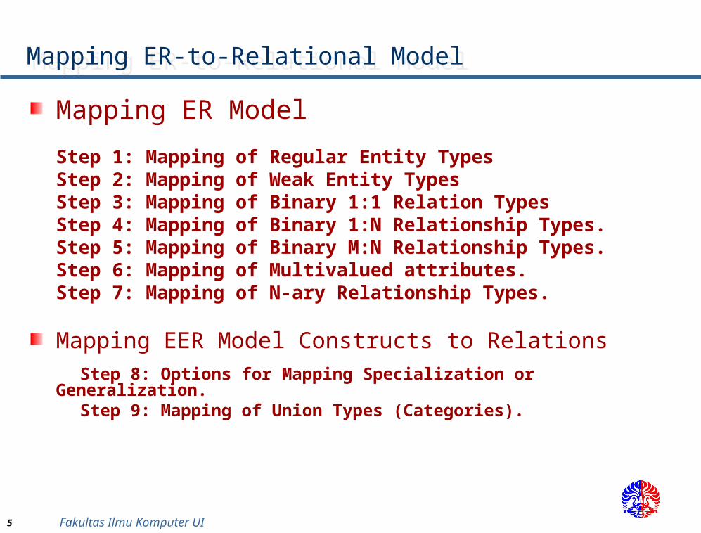
Mapping ER-to-Relational Model Mapping ER-to-Relational Model
Mapping ER Model
Step 1: Mapping of Regular Entity TypesStep 2: Mapping of Weak Entity TypesStep 3: Mapping of Binary 1:1 Relation TypesStep 4: Mapping of Binary 1:N Relationship Types.Step 5: Mapping of Binary M:N Relationship Types.Step 6: Mapping of Multivalued attributes.Step 7: Mapping of N-ary Relationship Types.
Mapping EER Model Constructs to Relations Step 8: Options for Mapping Specialization or Generalization. Step 9: Mapping of Union Types (Categories).
6 Fakultas Ilmu Komputer UI
Step 1: Mapping of Regular Entity TypesStep 1: Mapping of Regular Entity Types
For each regular (strong) entity type E in the ER schema, create a relation R that includes all the simple attributes of E. Include only the simple attributes of composite attributeChoose one of the key attributes of E as the primary key for R. If the chosen key of E is composite, the set of simple attributes that form it will together form the primary key of R.
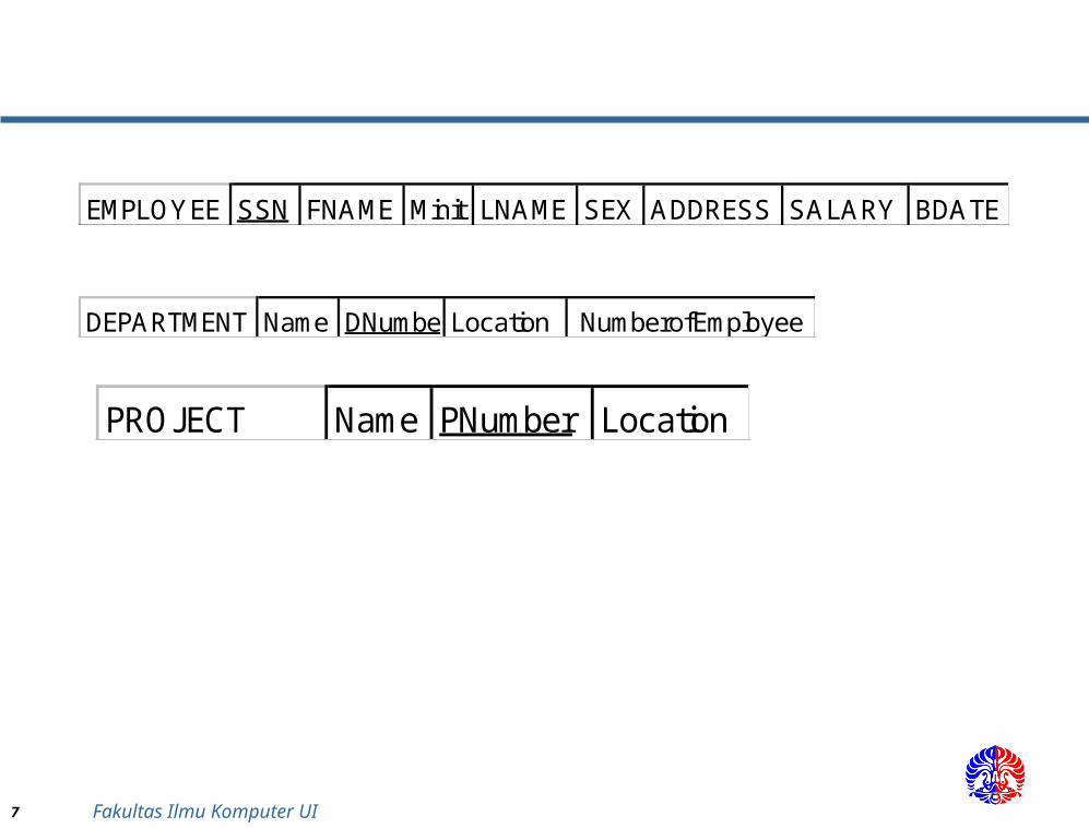
Example: We create the relations EMPLOYEE, DEPARTMENT, and PROJECT in the relational schema corresponding to the regular entities in the ER diagram. SSN, DNUMBER, and PNUMBER are the primary keys for the relations EMPLOYEE, DEPARTMENT, and PROJECT as shown.
7 Fakultas Ilmu Komputer UI
EMPLOYEE SSN FNAME Minit LNAME SEX ADDRESS SALARY BDATE
DEPARTMENT Name DNumberLocation NumberofEmployee
PROJECT Name PNumber Location
8 Fakultas Ilmu Komputer UI
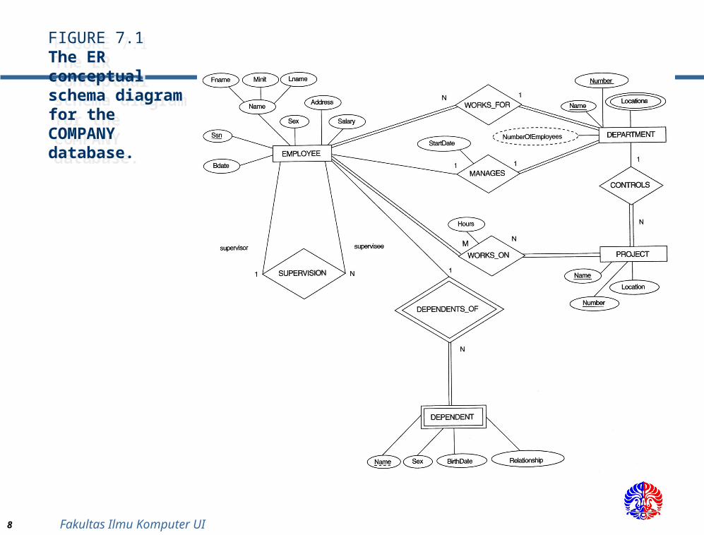
FIGURE 7.1The ER conceptual schema diagram for the COMPANY database.
FIGURE 7.1The ER conceptual schema diagram for the COMPANY database.
9 Fakultas Ilmu Komputer UI
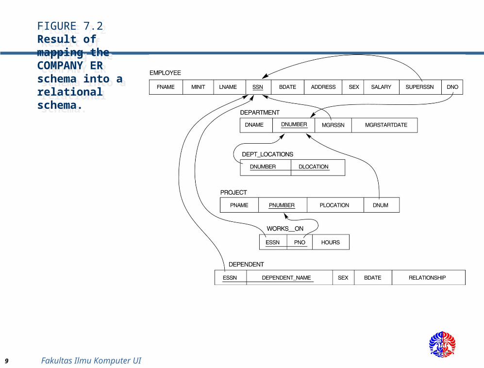
FIGURE 7.2Result of mapping the COMPANY ER schema into a relational schema.
FIGURE 7.2Result of mapping the COMPANY ER schema into a relational schema.
10 Fakultas Ilmu Komputer UI
Step 2: Mapping of Weak Entity Types Step 2: Mapping of Weak Entity Types
For each weak entity type W in the ER schema with owner entity type E, create a relation R and include all simple attributes (or simple components of composite attributes) of W as attributes of R.In addition, include as foreign key attributes of R the primary key attribute(s) of the relation(s) that correspond to the owner entity type(s).The primary key of R is the combination of the primary key(s) of the owner(s) and the partial key of the weak entity type W, if any.
Example: Create the relation DEPENDENT in this step to correspond to the weak entity type DEPENDENT. Include the primary key SSN of the EMPLOYEE relation as a foreign key attribute of DEPENDENT (renamed to ESSN).
The primary key of the DEPENDENT relation is the combination {ESSN, DEPENDENT_NAME} because DEPENDENT_NAME is the partial key of DEPENDENT.
11 Fakultas Ilmu Komputer UI
Step 3: Mapping of Binary 1:1 Relation TypesStep 3: Mapping of Binary 1:1 Relation Types
For each binary 1:1 relationship type R in the ER schema, identify the relations S and T that correspond to the entity types participating in R. There are three possible approaches:
(1) Foreign Key approach: Choose one of the relations-S, say-and include a foreign key in S the primary key of T. It is better to choose an entity type with total participation in R in the role of S.
Example: 1:1 relation MANAGES is mapped by choosing the participating entity type DEPARTMENT to serve in the role of S, because its participation in the MANAGES relationship type is total.
(2) Merged relation option: An alternate mapping of a 1:1 relationship type is possible by merging the two entity types and the relationship into a single relation. This may be appropriate when both participations are total.
12 Fakultas Ilmu Komputer UI
Step 4: Mapping of Binary 1:N Relationship Types.
Step 4: Mapping of Binary 1:N Relationship Types.
For each regular binary 1:N relationship type R, identify the relation S that represent the participating entity type at the N-side of the relationship type. Include as foreign key in S the primary key of the relation T that represents the other entity type participating in R. Include any simple attributes of the 1:N relation type as attributes of S.
Example: 1:N relationship types WORKS_FOR, CONTROLS, and SUPERVISION in the figure. For WORKS_FOR we include the primary key DNUMBER of the DEPARTMENT relation as foreign key in the EMPLOYEE relation and call it DNO.
13 Fakultas Ilmu Komputer UI
Step 5: Mapping of Binary M:N Relationship Types. Step 5: Mapping of Binary M:N Relationship Types.
For each regular binary M:N relationship type R, create a new relation S to represent R. Include as foreign key attributes in S the primary keys of the relations that represent the participating entity types; their combination will form the primary key of S. Also include any simple attributes of the M:N relationship type (or simple components of composite attributes) as attributes of S.
Example: The M:N relationship type WORKS_ON from the ER diagram is mapped by creating a relation WORKS_ON in the relational database schema. The primary keys of the PROJECT and EMPLOYEE relations are included as foreign keys in WORKS_ON and renamed PNO and ESSN, respectively.
Attribute HOURS in WORKS_ON represents the HOURS attribute of the relation type. The primary key of the WORKS_ON relation is the combination of the foreign key attributes {ESSN, PNO}.
14 Fakultas Ilmu Komputer UI
Step 6: Mapping of Multivalued attributes.Step 6: Mapping of Multivalued attributes.
For each multivalued attribute A, create a new relation R. This relation R will include an attribute corresponding to A, plus the primary key attribute K-as a foreign key in R-of the relation that represents the entity type of relationship type that has A as an attribute. The primary key of R is the combination of A and K. If the multivalued attribute is composite, we include its simple components.
Example: The relation DEPT_LOCATIONS is created. The attribute DLOCATION represents the multivalued attribute LOCATIONS of DEPARTMENT, while DNUMBER-as foreign key-represents the primary key of the DEPARTMENT relation. The primary key of R is the combination of {DNUMBER, DLOCATION}.
15 Fakultas Ilmu Komputer UI
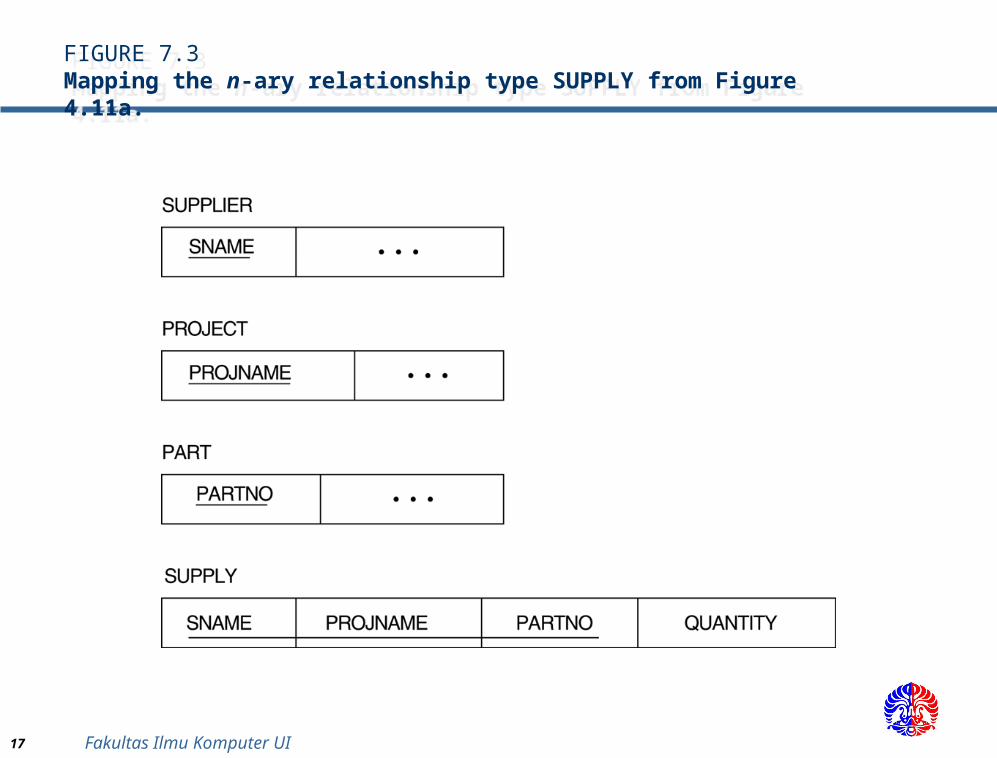
Step 7: Mapping of N-ary Relationship Types.Step 7: Mapping of N-ary Relationship Types.
For each n-ary relationship type R, where n>2, create a new relationship S to represent R.Include as foreign key attributes in S the primary keys of the relations that represent the participating entity types. Also include any simple attributes of the n-ary relationship type (or simple components of composite attributes) as attributes of S.
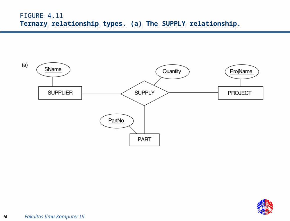
Example: The relationship type SUPPY in the ER below. This can be mapped to the relation SUPPLY shown in the relational schema, whose primary key is the combination of the three foreign keys {SNAME, PARTNO, PROJNAME}
16 Fakultas Ilmu Komputer UI
FIGURE 4.11Ternary relationship types. (a) The SUPPLY relationship.
FIGURE 4.11Ternary relationship types. (a) The SUPPLY relationship.
17 Fakultas Ilmu Komputer UI
FIGURE 7.3Mapping the n-ary relationship type SUPPLY from Figure 4.11a.
FIGURE 7.3Mapping the n-ary relationship type SUPPLY from Figure 4.11a.
18 Fakultas Ilmu Komputer UI
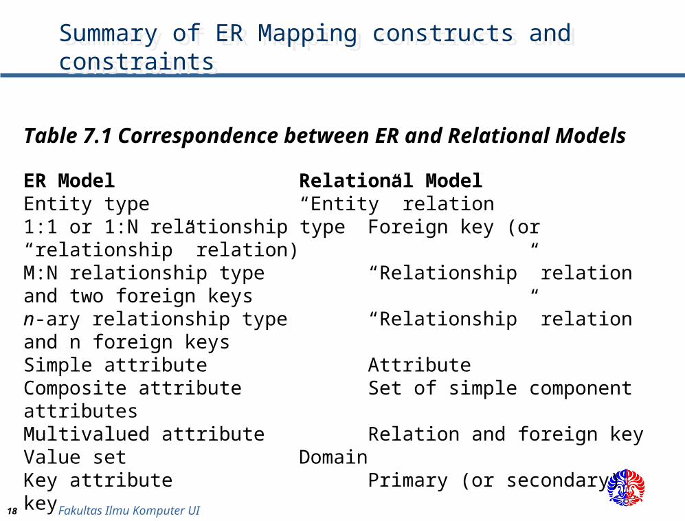
Summary of ER Mapping constructs and constraintsSummary of ER Mapping constructs and constraints
Table 7.1 Correspondence between ER and Relational Models
ER Model Relational ModelEntity type “Entity” relation1:1 or 1:N relationship type Foreign key (or “relationship” relation)M:N relationship type “Relationship” relation and two foreign keysn-ary relationship type “Relationship” relation and n foreign keysSimple attribute AttributeComposite attribute Set of simple component attributesMultivalued attribute Relation and foreign keyValue set DomainKey attribute Primary (or secondary) key
19 Fakultas Ilmu Komputer UI
Mapping EER Model Constructs to Relations Mapping EER Model Constructs to Relations
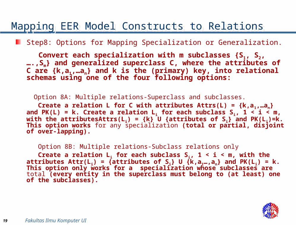
Step8: Options for Mapping Specialization or Generalization.
Convert each specialization with m subclasses {S1, S2,….,Sm} and generalized superclass C, where the attributes of C are {k,a1,…an} and k is the (primary) key, into relational schemas using one of the four following options:
Option 8A: Multiple relations-Superclass and subclasses. Create a relation L for C with attributes Attrs(L) = {k,a1,…an} and PK(L)
= k. Create a relation Li for each subclass Si, 1 < i < m, with the attributesAttrs(Li) = {k} U {attributes of Si} and PK(Li)=k. This option works for any specialization (total or partial, disjoint of over-lapping).
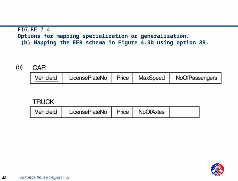
Option 8B: Multiple relations-Subclass relations only Create a relation Li for each subclass Si, 1 < i < m, with the attributes
Attr(Li) = {attributes of Si} U {k,a1…,an} and PK(Li) = k. This option only works for a specialization whose subclasses are total (every entity in the superclass must belong to (at least) one of the subclasses).
20 Fakultas Ilmu Komputer UI
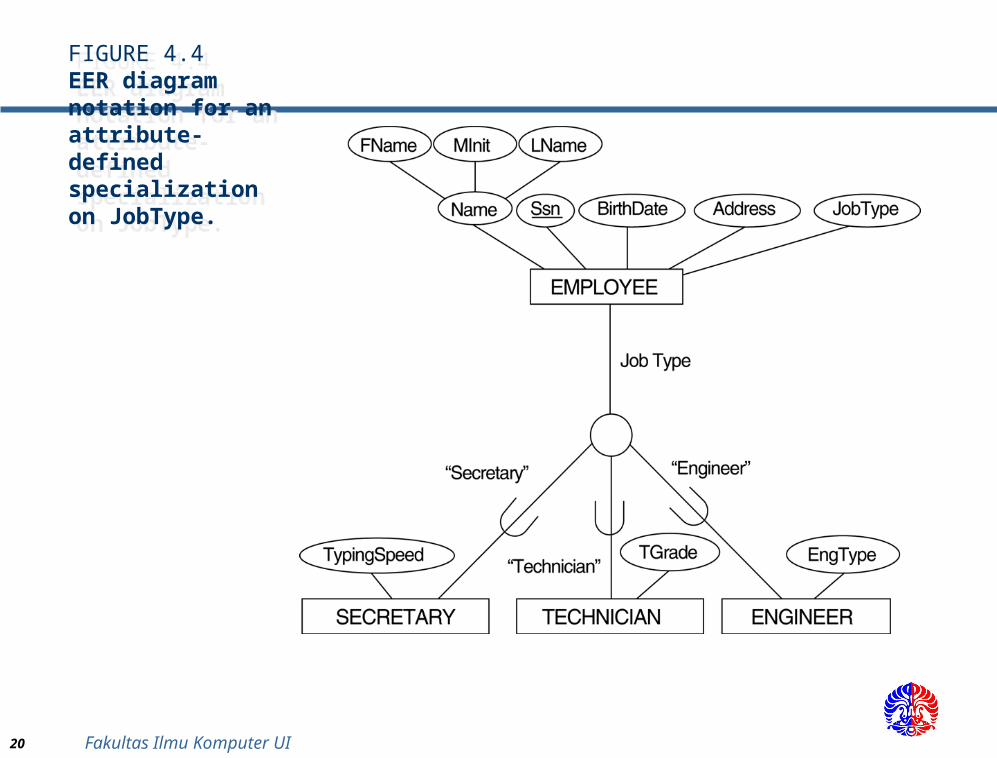
FIGURE 4.4EER diagram notation for an attribute-defined specialization on JobType.
FIGURE 4.4EER diagram notation for an attribute-defined specialization on JobType.
21 Fakultas Ilmu Komputer UI
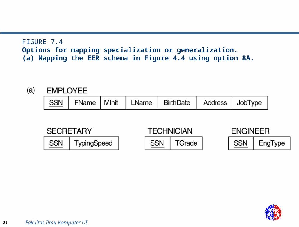
FIGURE 7.4Options for mapping specialization or generalization. (a) Mapping the EER schema in Figure 4.4 using option 8A.
22 Fakultas Ilmu Komputer UI
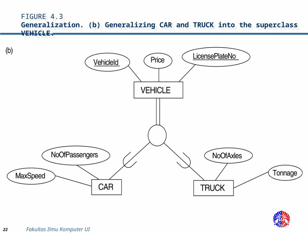
FIGURE 4.3Generalization. (b) Generalizing CAR and TRUCK into the superclass VEHICLE.
FIGURE 4.3Generalization. (b) Generalizing CAR and TRUCK into the superclass VEHICLE.
23 Fakultas Ilmu Komputer UI
FIGURE 7.4Options for mapping specialization or generalization. (b) Mapping the EER schema in Figure 4.3b using option 8B.
24 Fakultas Ilmu Komputer UI
Mapping EER Model Constructs to Relations (cont)Mapping EER Model Constructs to Relations (cont)
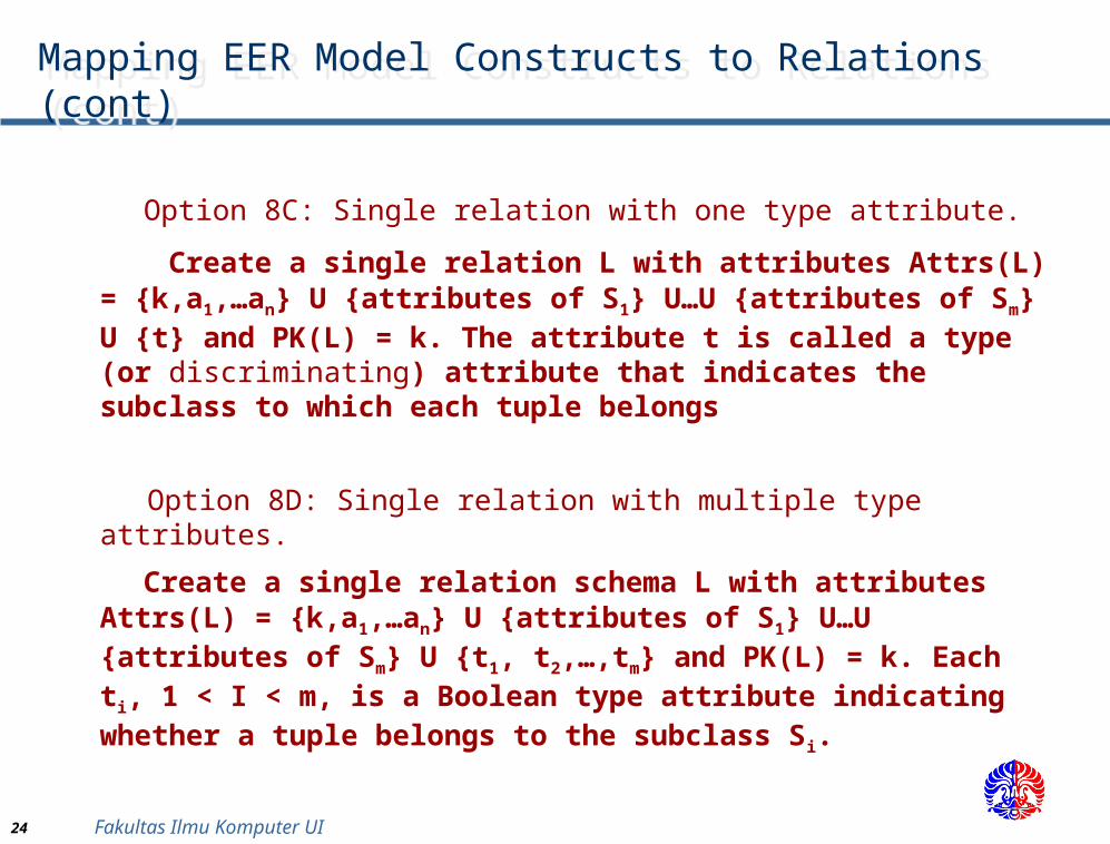
Option 8C: Single relation with one type attribute. Create a single relation L with attributes Attrs(L) =
{k,a1,…an} U {attributes of S1} U…U {attributes of Sm} U {t} and PK(L) = k. The attribute t is called a type (or discriminating) attribute that indicates the subclass to which each tuple belongs
Option 8D: Single relation with multiple type attributes.
Create a single relation schema L with attributes Attrs(L) = {k,a1,…an} U {attributes of S1} U…U {attributes of Sm} U {t1, t2,…,tm} and PK(L) = k. Each ti, 1 < I < m, is a Boolean type attribute indicating whether a tuple belongs to the subclass Si.

25 Fakultas Ilmu Komputer UI
FIGURE 4.4EER diagram notation for an attribute-defined specialization on JobType.
FIGURE 4.4EER diagram notation for an attribute-defined specialization on JobType.
26 Fakultas Ilmu Komputer UI
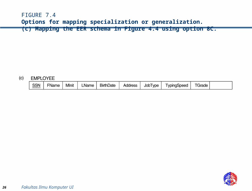
FIGURE 7.4Options for mapping specialization or generalization. (c) Mapping the EER schema in Figure 4.4 using option 8C.
27 Fakultas Ilmu Komputer UI
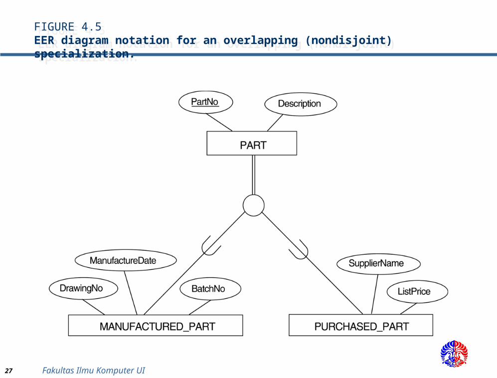
FIGURE 4.5EER diagram notation for an overlapping (nondisjoint) specialization.
FIGURE 4.5EER diagram notation for an overlapping (nondisjoint) specialization.
28 Fakultas Ilmu Komputer UI
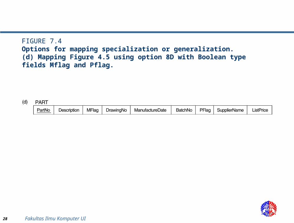
FIGURE 7.4Options for mapping specialization or generalization. (d) Mapping Figure 4.5 using option 8D with Boolean type fields Mflag and Pflag.
29 Fakultas Ilmu Komputer UI
Mapping EER Model Constructs to Relations (cont)Mapping EER Model Constructs to Relations (cont)
Mapping of Shared Subclasses (Multiple Inheritance)
A shared subclass, such as STUDENT_ASSISTANT, is a subclass of several classes, indicating multiple inheritance. These classes must all have the same key attribute; otherwise, the shared subclass would be modeled as a category.
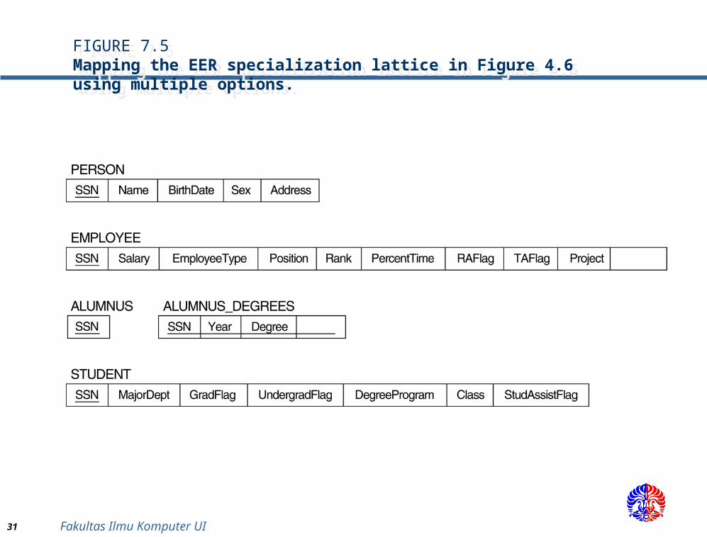
We can apply any of the options discussed in Step 8 to a shared subclass, subject to the restriction discussed in Step 8 of the mapping algorithm. Below both 8C and 8D are used for the shared class STUDENT_ASSISTANT.
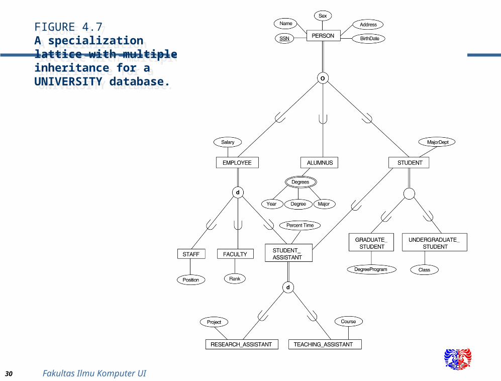
30 Fakultas Ilmu Komputer UI
FIGURE 4.7A specialization lattice with multiple inheritance for a UNIVERSITY database.
FIGURE 4.7A specialization lattice with multiple inheritance for a UNIVERSITY database.
31 Fakultas Ilmu Komputer UI
FIGURE 7.5Mapping the EER specialization lattice in Figure 4.6 using multiple options.
FIGURE 7.5Mapping the EER specialization lattice in Figure 4.6 using multiple options.
32 Fakultas Ilmu Komputer UI
Mapping EER Model Constructs to Relations (cont)Mapping EER Model Constructs to Relations (cont)
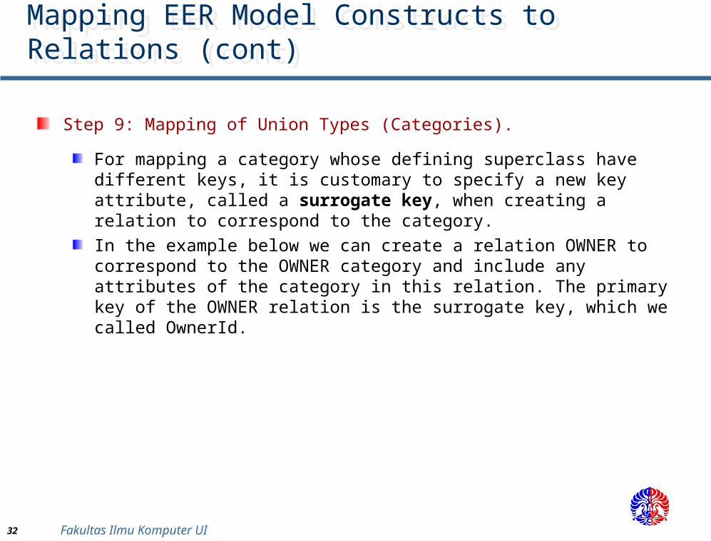
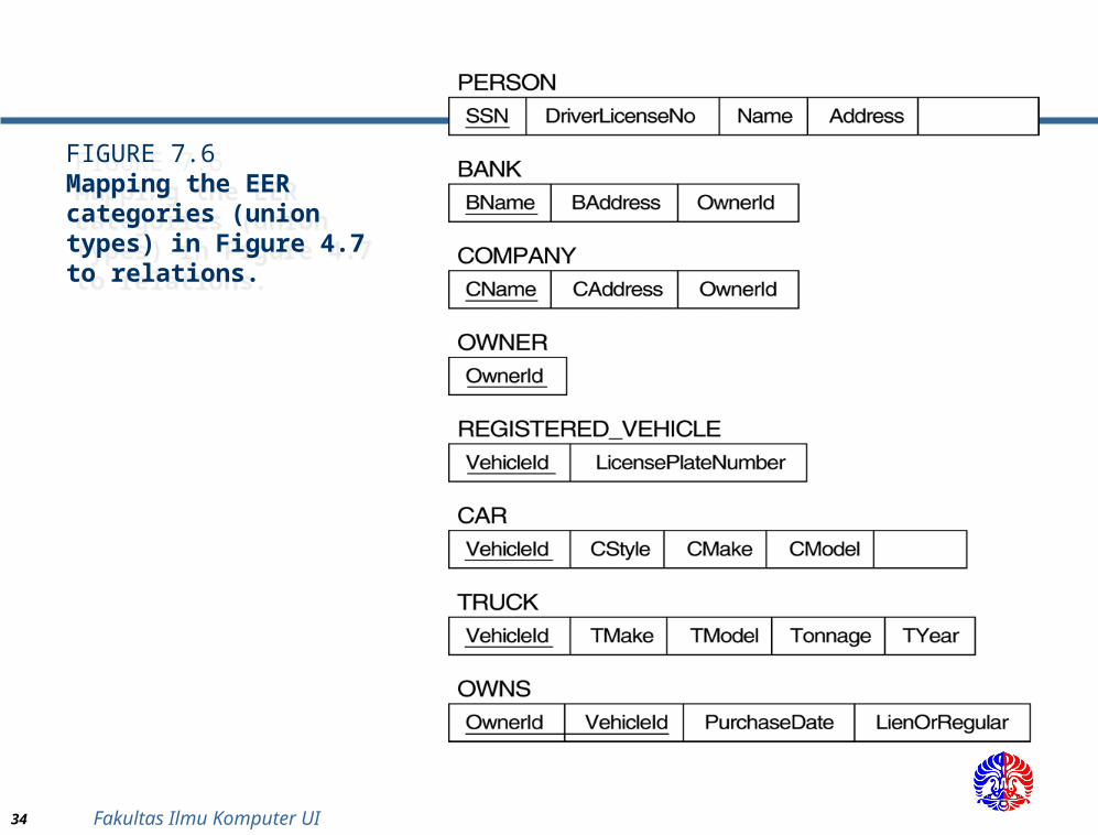
Step 9: Mapping of Union Types (Categories).
For mapping a category whose defining superclass have different keys, it is customary to specify a new key attribute, called a surrogate key, when creating a relation to correspond to the category. In the example below we can create a relation OWNER to correspond to the OWNER category and include any attributes of the category in this relation. The primary key of the OWNER relation is the surrogate key, which we called OwnerId.
33 Fakultas Ilmu Komputer UI
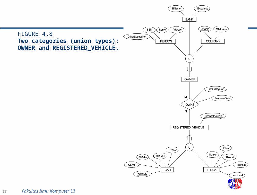
FIGURE 4.8Two categories (union types): OWNER and REGISTERED_VEHICLE.
FIGURE 4.8Two categories (union types): OWNER and REGISTERED_VEHICLE.
34 Fakultas Ilmu Komputer UI
FIGURE 7.6Mapping the EER categories (union types) in Figure 4.7 to relations.
FIGURE 7.6Mapping the EER categories (union types) in Figure 4.7 to relations.
35 Fakultas Ilmu Komputer UI
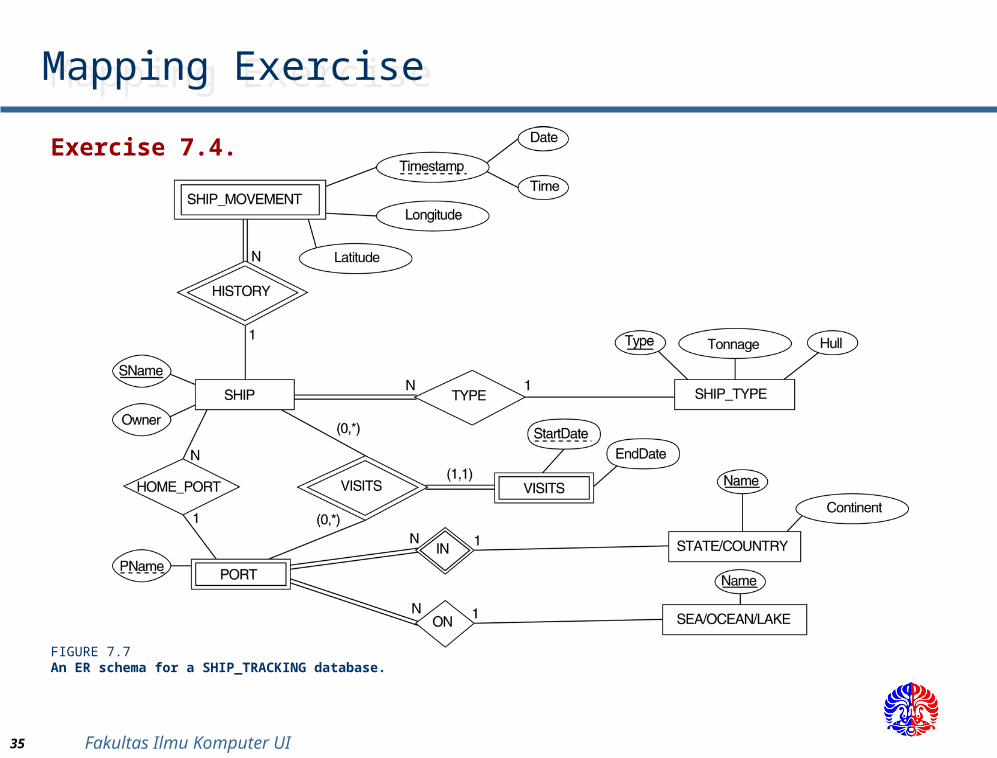
Mapping ExerciseMapping Exercise
Exercise 7.4.
FIGURE 7.7An ER schema for a SHIP_TRACKING database.