Map Reading and Land Navigation - eMilitary Manuals · · 2013-12-05*FM 21-26 FIELD MANUAL...
20
*FM 21-26 FIELD MANUAL HEADQUARTERS No. 21-26 DEPARTMENT OF THE ARMY Washington, DC, 7 May 1993 MAP READING AND LAND NAVAGATION CONTENTS Page Preface .................................................................................................................... ..v Part One. MAP READING Chapter 1. TRAINING STRATEGY 1-1. The Building-Block Approach .......................................................................... 1-1 1-2. Armywide Implementation ................................................................................ 1-2 1-3. Safety............................................................................................................... 1-2 Chapter 2. MAPS 2-1. Definition ......................................................................................................... 2-1 2-2. Purpose ............................................................................................................ 2-1 2-3. Procurement ..................................................................................................... 2-1 2-4. Security ............................................................................................................ 2-2 2-5. Care ................................................................................................................. 2-2 2-6. Categories........................................................................................................ 2-2 2-7. Military Map Substitutes ................................................................................... 2-4 2-8. Standards of Accuracy ...................................................................................... 2-4 Chapter 3. MARGINAL INFORMATION AND SYMBOLS 3-1. Marginal Information on a Military Map ........................................................... 3-1 3-2. Additional Notes ............................................................................................... 3-4 3-3. Topographic Map Symbols ............................................................................... 3-4 3-4. Military Symbols ............................................................................................... 3-4 3-5. Colors Used on a Military Map ......................................................................... 3-5 DISTRIBUTION RESTRICTION : Approved for public release; distribution is unlimited. *This publication supersedes FM 21 -26, 30 September 1987. i Manual Provided by eMilitary Manuals - http://www.emilitarymanuals.com
Transcript of Map Reading and Land Navigation - eMilitary Manuals · · 2013-12-05*FM 21-26 FIELD MANUAL...

*FM 21-26
FIELD MANUAL HEADQUARTERSNo. 21-26 DEPARTMENT OF THE ARMY
Washington, DC, 7 May 1993
MAP READING AND LAND NAVAGATION
CONTENTS
Page
Preface .................................................................................................................... ..v
Part One. MAP READING
Chapter 1. TRAINING STRATEGY1-1. The Building-Block Approach .......................................................................... 1-11-2. Armywide Implementation................................................................................ 1-21-3. Safety............................................................................................................... 1-2
Chapter 2. MAPS2-1. Definition......................................................................................................... 2-12-2. Purpose............................................................................................................ 2-12-3. Procurement..................................................................................................... 2-12-4. Security............................................................................................................ 2-22-5. Care .................................................................................................................2-22-6. Categories........................................................................................................ 2-22-7. Military Map Substitutes...................................................................................2-42-8. Standards of Accuracy......................................................................................2-4
Chapter 3. MARGINAL INFORMATION AND SYMBOLS3-1. Marginal Information on a Military Map...........................................................3-13-2. Additional Notes...............................................................................................3-43-3. Topographic Map Symbols............................................................................... 3-43-4. Military Symbols...............................................................................................3-43-5. Colors Used on a Military Map......................................................................... 3-5
DISTRIBUTION RESTRICTION: Approved for public release; distribution is unlimited.
*This publication supersedes FM 21-26, 30 September 1987.
i
Manual Provided by eMilitary Manuals - http://www.emilitarymanuals.com

FM 21-26
PageChapter 4. GRIDS
4-1. Reference System.............................................................................................4-14-2. Geographic Coordinates....................................................................................4-14-3. Military Grids...................................................................................................4-74-4. The US Army Military Grid Reference System..................................................4-94-5. Locating a Point Using Grid Coordinates........................................................4-124-6. Locating a Point Using the US Army Military Grid Reference System.............4-144-7. Grid Reference Box........................................................................................4-164-8. Other Grid Systems.........................................................................................4-174-9. Protection of Map Coordinates and Locations.................................................4-18
Chapter 5. SCALE AND DISTANCE5-1. Representative Fraction.....................................................................................5-15-2. Graphic (Bar) Scales.........................................................................................5-25-3. Other Methods..................................................................................................5-8
Chapter 6. DIRECTION6-1. Methods of Expressing Direction......................................................................6-16-2. Base Lines........................................................................................................6-16-3. Azimuths..........................................................................................................6-26-4. Grid Azimuths..................................................................................................6-26-5. Protractor .........................................................................................................6-46-6. Declination Diagram ........................................................................................6-66-7. Intersection.......................................................................................................6-96-8. Resection........................................................................................................6-106-9. Modified Resection.........................................................................................6-126-10. Polar Coordinates ........................................................................................6-12
Chapter 7. OVERLAYS7-1. Purpose............................................................................................................7-17-2. Map Overlay.....................................................................................................7-17-3. Aerial Photograph Overlay................................................................................7-3
Chapter 8. AERIAL PHOTOGRAPHS8-1. Comparison With Maps....................................................................................8-18-2. Types................................................................................................................8-18-3. Types of Film....................................................................................................8-58-4. Numbering and Titling Information...................................................................8-68-5. Scale Determination..........................................................................................8-68-6. Indexing............................................................................................................8-88-7. Orienting of Photograph.................................................................................8-11
ii
Manual Provided by eMilitary Manuals - http://www.emilitarymanuals.com

FM 21-26
Page8-8. Point Designation Grid................................................................................... 8-128-9. Identification of Photograph Features............................................................. 8-158-10. Stereovision.................................................................................................. 8-16
Part Two. LAND NAVIGATION
Chapter 9. NAVIGATION EQUIPMENT AND METHODS9-1. Types of Compasses......................................................................................... 9-19-2. Lensatic Compass.............................................................................................9-19-3. Compass Handling............................................................................................ 9-19-4. Using a Compass..............................................................................................9-29-5. Field-Expedient Methods.................................................................................. 9-69-6. Global Positioning System.............................................................................. 9-10
Chapter 10. ELEVATION AND RELIEF10-1. Definitions.................................................................................................... 10-110-2. Methods of Depicting Relief......................................................................... 10-110-3. Contour Intervals.......................................................................................... 10-210-4. 7 Types of Slopes......................................................................................... 10-410-5. Percentage of Slope...................................................................................... 10-610-6. Terrain Features............................................................................................ 10-910-7. Interpretation of Terrain Features............................................................... 10-1410-8. Profiles....................................................................................................... 10-16
Chapter 11. TERRAIN ASSOCIATION11-1. Orienting the Map......................................................................................... 11-111-2. Locations...................................................................................................... 11-411-3. Terrain Association Usage............................................................................ 11-411-4. Tactical Considerations................................................................................. 11-611-5. Movement and Route Selection.................................................................... 11-811-6. Navigation Methods..................................................................................... 11-911-7. Night Navigation........................................................................................ 11-12
Chapter 12. MOUNTED LAND NAVIGATION12-1. Principles...................................................................................................... 12-112-2. Navigator's Duties........................................................................................ 12-112-3. Movement.................................................................................................... 12-112-4. Terrain Association Navigation..................................................................... 12-312-5. Dead Reckoning Navigation......................................................................... 12-412-6. Stabilized Turret Alignment Navigation........................................................ 12-512-7. Combination Navigation............................................................................... 12-5
iii
Manual Provided by eMilitary Manuals - http://www.emilitarymanuals.com

FM 21-26
Page
Chapter 13. NAVIGATION IN DIFFERENT TYPES OF TERRAIN13-1. Desert Terrain...............................................................................................13-113-2. Mountain Terrain..........................................................................................13-313-3. Jungle Terrain...............................................................................................13-413-4. Arctic Terrain...............................................................................................13-613-5. Urban Areas..................................................................................................13-7
Chapter 14. UNIT SUSTAINMENT14-1. Set Up a Sustainment Program......................................................................14-114-2. Set Up a Train-the-Trainer Program..............................................................14-114-3. Set Up a Land Navigation Course.................................................................14-2
Appendix A FIELD SKETCHING..........................................................................................A-1
Appendix B. MAP FOLDING TECHNIQUES....................................................................... B-1
Appendix C. UNITS OF MEASURE AND CONVERSION FACTORS............................ ...C-1
Appendix D. JOINT OPERATIONS GRAPHICS..................................................................D-1
Appendix E. EXPORTABLE TRAINING MATERIAL........................................................ E-1
Appendix F. ORIENTEERING................................................................................................F-1
Appendix G. M2 COMPASS ...................................................................................................G-1
Appendix H. ADDITIONAL AIDS..........................................................................................H-1
Appendix I. FOREIGN MAPS.................................................................................................. I-1
Appendix J. GLOBAL POSITIONING SYSTEM.. ................................................................. J-1
GLOSSARY................................................................................................................. Glossary-1
REFERENCES..........................................................................................................References-1
INDEX ......................................................................................................................... Index-1
iv
Manual Provided by eMilitary Manuals - http://www.emilitarymanuals.com
PREFACE
The purpose of this field manual is to provide a standardized source document forArmywide reference on map reading and land navigation. It applies to every soldier in the Armyregardless of service branch, MOS, or rank. This manual contains both doctrine and trainingguidance on these subjects. Part One addresses map reading and Part Two, land navigation. Theappendixes include a list of exportable training materials, a matrix of land navigation tasks, anintroduction to orienteering, and a discussion of several devices that can assist the soldier inland navigation.
The proponent of this publication is the US Army Infantry School. Send comments andrecommendations on DA Form 2028 directly to Commandant, US Army Infantry School,ATTN: ATSH-IN-S3, Fort Benning, GA 31905-5596.
Unless this publication states otherwise, masculine nouns and pronouns do not referexclusively to men.
v
Manual Provided by eMilitary Manuals - http://www.emilitarymanuals.com

PART ONEMAP READING
CHAPTER 1TRAINING STRATEGY
This manual is in to an Armywide need for a new map reading and land navigationtraining strategy based on updated doctrine. This chapter describes and illustrates thisapproach to teaching these skills.
1-1. THE BUILDING-BLOCK APPROACHInstitution courses are designed to prepare the soldierfor a more advanced duty position in his unit. Thecritical soldiering skills of move, shoot, andcommunicate must be trained, practiced, and sustainedat every level in the schools as well as in the unit. Themap reading and land navigation skills taught at eachlevel are critical to the soldiering skills of the dutyposition for which he is being school-trained.Therefore, they are also a prerequisite for a critical skillat a more advanced level.
a. A soldier completing initial entry training mustbe prepared to become a team member. He must beproficient in the basic map reading and dead reckoningskills.
b. After completing the primary leadershipdevelopment course, a soldier should be ready to be ateam leader. This duty position requires expertise in theskills of map reading, dead reckoning, and terrainassociation.
c. A soldier completing the basic NCO course hasbeen trained for the squad leader position. Map readingand land navigation at skill level 3 requiresdevelopment of problem-solving skills; for example,route selection and squad tactical movement.
d. At skill level 4, the soldier completing theadvanced NCO course is prepared to assume the dutyposition of platoon sergeant or operations NCO.Planning tactical movements, developing unitsustainment, and making decisions are the importantland navigation skills at this level.
e. Officers follow similar progression. A newsecond lieutenant must have mastered map reading andland navigation skills, and have an aptitude for deadreckoning and terrain association.
(1) After completing a branch-specific officer basiccourse, the officer must be prepared to assume the dutiesand responsibilities of a platoon leader. He will berequired to execute the orders and operations of his
commander. Map reading and land navigation at thislevel require development of the problem-solving skillsof route selection and tactical movement.
(2) After completing the officer advanced course,the officer is prepared to assume the duties andresponsibilities of a company commander or primarystaff officer. The commander must plan and executeoperations with full consideration to all aspects ofnavigation. The staff officer must recommendbattlefield placement of all administrative, logistical,and personnel resources. These recommendationscannot be tactically sound unless the estimate processincludes a detailed analysis of the area of operations.This ability requires expertise in all map reading andnavigation skills to include the use of nonmilitary maps,aerial photographs, and terrain analysis with respect toboth friendly and enemy forces. The commander/staffofficer must plan and execute a program to develop theunit's Train the Trainer Program for land navigation.
f. A program of demonstrated proficiency of allthe preceding skill levels to the specified conditions andstandards is a prerequisite to the successfulimplementation of a building-block training approach.This approach will reflect duty position responsibilitiesin map reading and land navigation. An understandingof the fundamental techniques of dead reckoning orfield-expedient methods is a basic survival skill thateach soldier must develop at the initial entry level. Thisprovides a support foundation for more interpretiveanalysis at intermediate skill levels 2 and 3, with finalprogression to level 4. Mastery of all map reading andland navigation tasks required in previous duty positionsis essential for the sequential development ofincreasingly difficult abilities. This building-blockapproach is supported by scope statements. It is part ofthe training doctrine at each level in the institutionaltraining environment of each course.
1-1
Manual Provided by eMilitary Manuals - http://www.emilitarymanuals.com

FM 21-26
g. Exportable training end instructor support/cer-tification packages, based upon the updated map readingand land navigation field manual, are being developed.Innovative training devices and materials are beingdeveloped for use in the institution, ROTC regions, andthe field. (See Appendixes E and H.)
1-2. ARMYWIDE IMPLEMENTATIONA mandatory core of critical map reading and land navi-gation tasks and a list of electives will be provided toeach TRADOC service school and FORSCOMprofessional development school. Standardization will beachieved through the mandatory core. Exportable
training material will be made available to supportArmywide implementation.
1-3. SAFETYPlan to brief and enforce all safety regulations establishedby local range control. Coordinate the mode ofevacuation of casualties through the appropriatechannels. Review all installation safety regulations.Unit leaders must complete a thorough terrainreconnaissance before using an area for land navigationtraining. They should look for dangerous terrain, heavytrafficked roads, water obstacles, wildlife, and trainingdebris.
1-2
Manual Provided by eMilitary Manuals - http://www.emilitarymanuals.com
CHAPTER 2
MAPS
Cartography is the art and science of expressing the known physical features of the earthgraphical by maps and charts. No one knows who drew, molded, laced together, orscratched out us the dirt the first map. But a study of history reveals that the most pressingdemands for accuracy and detail in mapping have come as the result of military needs.Today, the complexities of tactical operations and deployment of troops is such that it isessential for all soldiers to be able to read and interpret their maps in order to move quicklyand effectively on the battlefield. This chapter explains maps; it includes the definition andpurpose of a map and describes map security, types, categories, and scales.
2-1. DEFINITIONA map is a graphic representation of a portion of theearth's surface drawn to scale, as seen from above. Ituses colors, symbols, and labels to represent featuresfound on the ground. The ideal representation would berealized if every feature of the area being mapped couldbe shown in true shape. Obviously this is impossible, andan attempt to plot each feature true to scale would resultin a product impossible to read even with the aid of amagnifying glass.
a. Therefore, to be understandable, features mustbe represented by conventional signs and symbols. To belegible, many of these must be exaggerated in size, oftenfar beyond the actual ground limits of the featurerepresented. On a 1:250,000 scale map, the prescribedsymbol for a building covers an area about 500 feetsquare on the ground; a road symbol is equivalent to aroad about 520 feet wide on the ground; the symbol for asingle-track railroad (the length of a cross-tie) isequivalent to a railroad cross-tie about 1,000 feet on theground.
b. The portrayal of many features requires similarexaggeration. Therefore, both the selection of features tobe shown, as well as their portrayal, are in accord withthe guidance established by the Defense MappingAgency.
2-2. PURPOSEA map provides information on the existence, the loca-tion of, and the distance between ground features, such aspopulated places and routes of travel and communication.It also indicates variations in terrain, heights of naturalfeatures, and the extent of vegetation cover. With ourmilitary forces dispersed throughout the world, it isnecessary to rely on maps to provide information to ourcombat elements and to resolve logistical operations farfrom our shores. Soldiers and materials must betransported, stored, and placed into operation at the
proper time and place. Much of this planning must bedone by using maps. Therefore, any operation requires asupply of maps; however, the finest maps available areworthless unless the map user knows how to read them.
2-3. PROCUREMENTMost military units are authorized a basic load of maps.Local command supplements to AR 115-11 providetables of initial allowances for maps. Map requisitionsand distribution follow the channels of Defense MappingAgency Hydrographic, Topographic Center's Office ofDistribution and Services. In the division, however,maps are a responsibility of the G2 section.
a. To order a map, refer to the DMA cataloglocated at your S2/G2 shop. Part 3 of this catalog,Topographic Maps, has five volumes. Using thedelineated map index, find the map or maps you wantbased upon the location of the nearest city. With thisinformation, order maps using the following forms:
(1) Standard Form 344. It can be typed orhandwritten; it is used for mailing or over-the-counterservice.
(2) Department of Defense Form 1348. Same as SF344. You can order copies of only one map sheet on eachform.
(3) Department of Defense Form 1348M. This is apunch card form for AUDODIN ordering.
(4) Department of Defense Form 173. This is amessage form to be used for urgent ordering.
With the exception of the message form (DD 173), thenumbered sections of all forms are the same. Forexample:. In block 1, if you are in CONUS, enter"AOD;" if you are overseas, enter "AO4." In block 2, useone of the following codes for your location.
2-1
Manual Provided by eMilitary Manuals - http://www.emilitarymanuals.com
FM 21-26
Location CodeEurope CS7Hawaii HM9Korea WM4Alaska WC1Panama HMJCONUS HM8
Your supply section will help you fill out the rest of theform.
b. Stock numbers are also listed in map catalogs,which are available at division and higher levels andoccasionally in smaller units. A map catalog consists ofsmall-scale maps upon which the outlines of the individualmap sheets of a series have been delineated. Anotherdocument that is an aid to the map user is the gazetteer. Agazetteer lists all the names appearing on a map series of ageographical area, a designation that identifies what islocated at that place name, a grid reference, a sheet numberof the map upon which the name appeared, and the latitudeand longitude of the named features. Gazetteers areprepared for maps of foreign areas only.
2-4. SECURITYAll maps should be considered as documents that requirespecial handling. If a map falls into unauthorized hands, itcould easily endanger military operations by providinginformation of friendly plans or areas of interest to theenemy. Even more important would be a map on whichthe movements or positions of friendly soldiers weremarked. It is possible, even though the markings on a maphave been erased, to determine some of the informationthat had been marked upon it. Maps are documents thatmust not fall into unauthorized hands.
a. If a map is no longer needed, it must be turned into the proper authority. If a map is in danger of beingcaptured, it must be destroyed. The best method ofdestruction is by burning it and scattering the ashes. Ifburning is not possible, the map can be torn into smallpieces and scattered over a wide area.
b. Maps of some areas of the world are subject tothird party limitations. These are agreements that permitthe United States to make and use maps of another countryprovided these maps are not released to any third partywithout permission of the country concerned. Such mapsrequire special handling.
c. Some maps may be classified and must be handledand cared for in accordance with AR 380-5 and, ifapplicable, other local security directives.
2-5. CAREMaps are documents printed on paper and requireprotection from water, mud, and tearing. Wheneverpossible, a map should be carried in a waterproof case, in
a pocket, or in some other place where it is handy for usebut still protected.
a. Care must also be taken when using a map since itmay have to last a long time. If it becomes necessary tomark a map, the use of a pencil is recommended. Use lightlines so they may be erased easily without smearing andsmudging, or leaving marks that may cause confusionlater. If the map margins must be trimmed for any reason,it is essential to note any marginal information that may beneeded later, such as grid data and magnetic declination.
b. Special care should be taken of a map that isbeing used in a tactical mission, especially in small units;the mission may depend on that map. All members of suchunits should be familiar with the map's location at alltimes.
c. Appendix B shows two ways of folding a map.
2-6. CATEGORIESThe DMA's mission is to provide mapping, charting, andall geodesy support to the armed forces and all othernational security operations. DMA produces fourcategories of products and services: hydrographic,topographic, aeronautical, and missile and targeting.Military maps are categorized by scale and type.
a. Scale. Because a map is a graphic representationof a portion of the earth's surface drawn to scale as seenfrom above, it is important to know what mathematicalscale has been used. You must know this to determineground distances between objects or locations on the map,the size of the area covered, and how the scale may affectthe amount of detail being shown. The mathematical scaleof a map is the ratio or fraction between the distance on amap and the corresponding distance on the surface of theearth. Scale is reported as a representative fraction (RF)with the map distance as the numerator and the grounddistance as the denominator.
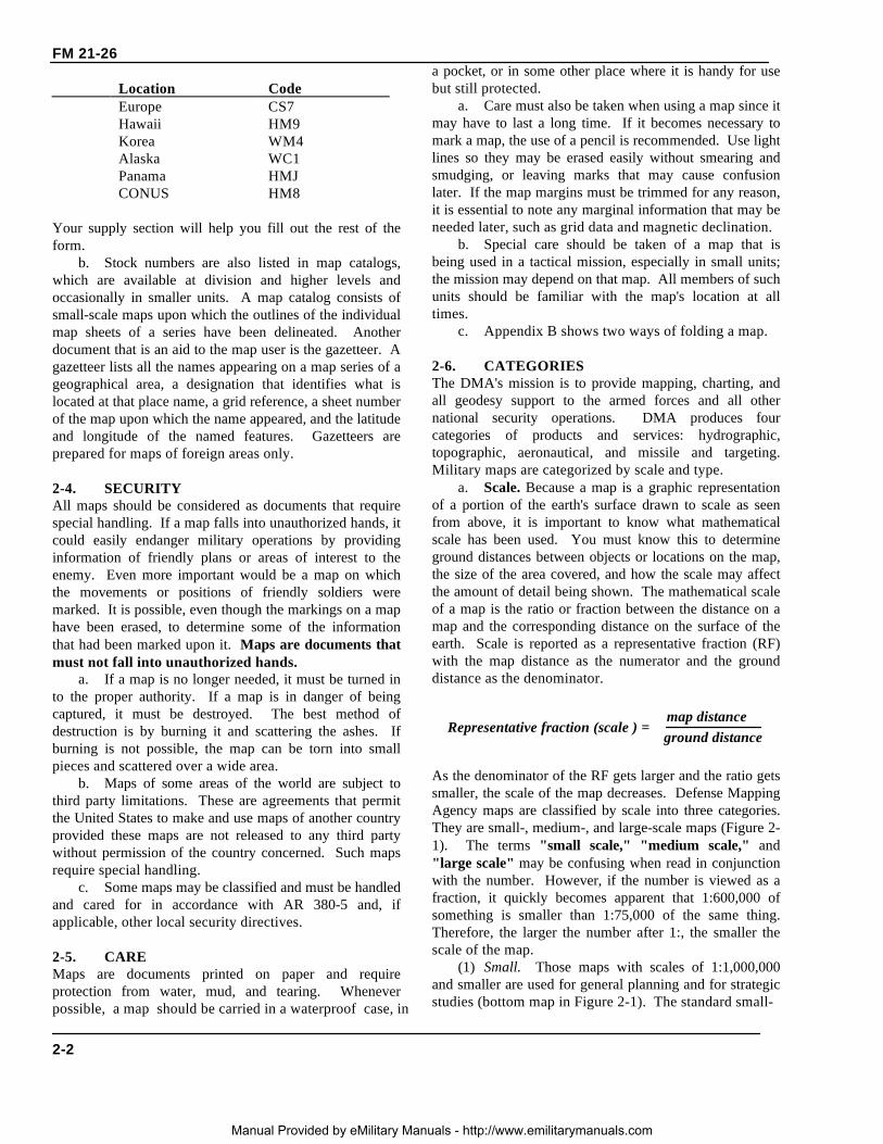
As the denominator of the RF gets larger and the ratio getssmaller, the scale of the map decreases. Defense MappingAgency maps are classified by scale into three categories.They are small-, medium-, and large-scale maps (Figure 2-1). The terms "small scale," "medium scale," and"large scale" may be confusing when read in conjunctionwith the number. However, if the number is viewed as afraction, it quickly becomes apparent that 1:600,000 ofsomething is smaller than 1:75,000 of the same thing.Therefore, the larger the number after 1:, the smaller thescale of the map.
(1) Small. Those maps with scales of 1:1,000,000and smaller are used for general planning and for strategicstudies (bottom map in Figure 2-1). The standard small-
ground distanceRepresentative fraction (scale ) =
map distance
2-2
Manual Provided by eMilitary Manuals - http://www.emilitarymanuals.com
FM 21-26
scale map is 1:1,000,000. This map covers a very largeland area at the expense of detail.
(2) Medium. Those maps with scales larger than1:1,000,000 but smaller than 1:75,000 are used foroperational planning (center map in Figure 2-1). Theycontain a moderate amount of detail, but terrain analysisis best done with the large-scale maps described below.The standard medium-scale map is 1:250,000. Mediumscale maps of 1:100,000 are also frequently encountered.
(3) Large. Those maps with scales of 1:75,000 andlarger are used for tactical, administrative, and logisticalplanning (top map in Figure 2-1). These are the mapsthat you as a soldier or junior leader are most likely toencounter. The standard large-scale map is 1:50,000;however, many areas have been mapped at a scale of1:25,000.
Figure 2-1. Scale classifications.
b. Types. The map of choice for land navigators isthe 1:50,000 scale military topographic map. It isimportant, however, that you know how to use the manyother products available from the DMA as well. Whenoperating in foreign places, you may discover that DMAmap products have not yet been produced to cover yourparticular area of operations, or they may not beavailable to your unit when you require them.Therefore, you must be prepared to use maps producedby foreign governments that may or may not meet thestandards for accuracy set by DMA. These maps oftenuse symbols that resemble those found on DMA mapsbut which have completed different meanings. Theremay be other times when you must operate with the onlymap you can obtain. This might be a commerciallyproduced map run off on a copy machine at higherheadquarters. In Grenada, many of our troops used aBritish tourist map.
(1) Planimetric map. This is a map that presentsonly the horizontal positions for the features represented.It is distinguished from a topographic map by theomission of relief, normally represented by contour lines.Some times, it is called a line map.
(2) Topographical map. This is a map thatportrays terrain features in a measurable way (usuallythrough use of contour lines), as well as the horizontalpositions of the features represented. The verticalpositions, or relief, are normally represented by contourlines on military topographic maps. On maps showingrelief, the elevations and contours are measured from aspecific vertical datum plane, usually mean sea level.Figure 3-1 shows a typical topographic map.
(3) Photomap. This is a reproduction of an aerialphotograph upon which grid lines, marginal data, placenames, route numbers, important elevations, boundaries,and approximate scale and direction have been added.(See Chapter 8)
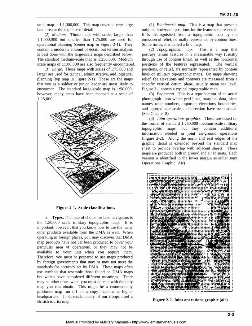
(4) Joint operations graphics. These are based onthe format of standard 1:250,000 medium-scale militarytopographic maps, but they contain additionalinformation needed in joint air-ground operations(Figure 2-2). Along the north and east edges of thegraphic, detail is extended beyond the standard mapsheet to provide overlap with adjacent sheets. Thesemaps are produced both in ground and air formats. Eachversion is identified in the lower margin as either JointOperations Graphic (Air)
Figure 2-2. Joint operations graphic (air).
2-3
Manual Provided by eMilitary Manuals - http://www.emilitarymanuals.com

FM 21-26
or Joint Operations Graphic (Ground). The topographicinformation is identical on both, but the ground versionshows elevations and contour in meters and the airversion shows them in feet. Layer (elevation) tinting andrelief shading are added as an aid to interpolating relief.Both versions emphasize airlanding facilities (shown inpurple), but the air version has additional symbols toidentify aids and obstructions to air navigation. (SeeAppendix D for additional information.)
(5) Photomosaic. This is an assembly of aerialphotographs that is commonly called a mosaic intopographic usage. Mosaics are useful when time doesnot permit the compilation of a more accurate map. Theaccuracy of a mosaic depends on the method employedin its preparation and may vary from simply a goodpictorial effect of the ground to that of a planimetricmap.
(6) Terrain model. This is a scale model of theterrain showing features, and in large-scale modelsshowing industrial and cultural shapes. It provides ameans for visualizing the terrain for planning orindoctrination purposes and for briefing on assaultlandings.
(7) Military city map. This is a topographic map(usually at 1:12,550 scale, sometimes up to 1:5,000),showing the details of a city. It delineates streets andshows street names, important buildings, and otherelements of the urban landscape important to navigationand military operations in urban terrain. The scale of amilitary city map depends on the importance and size ofthe city, density of detail, and available intelligenceinformation.
(8) Special maps These are maps for specialpurposes, such as trafficability, communications, andassault maps. They are usually in the form of anoverprint in the scales smaller than 1:100,000 but largerthan 1:1,000,000. A special purpose map is one that hasbeen designed or modified to give information notcovered on a standard map. The wide range of subjectsthat could be covered under the heading of specialpurpose maps prohibits, within the scope of this manual,more than a brief mention of a few important ones.Some of the subjects covered are:
• Terrain features.• Drainage characteristics.• Vegetation.• Climate.• Coasts and landing beaches.• Roads and bridges.• Railroads.• Airfields.• Urban areas.• Electric power.• Fuels.• Surface water resources.• Ground water resources.
• Natural construction materials.• Cross-country movements.• Suitability for airfield construction.• Airborne operations.
2 7. MILITARY MAP SUBSTITUTESIf military maps are not available, substitutes will haveto be used These can range from foreign military orcommercial maps to field sketches. The DMA canprovide black and white reproductions of many foreignmaps and can produce its own maps based uponintelligence
a. Foreign Maps. These are maps that have beencompiled by nations other than our own. When thesemust be used, the marginal information and grids arechanged to conform to our standards if time permits.The scales may differ from our maps, but they do expressthe ratio of map distant to ground distance and can beused in the same way. The legend must be used sincethe map symbols almost always differ from ours.Because the accuracy of foreign maps variesconsiderably, they are usually evaluated in regard toestablished accuracy standards before they are issued toour troops. (See Appendix K for additionalinformation.)
b. Atlases. Atlases are collections of maps ofregions, countries, continents, or the world. Such mapsare accurate only to a degree and can be used for generalinformation only.
c. Geographic Maps. These maps give an overallidea of the mapped area in relation to climate,population, relief, vegetation, and hydrography. Theyalso show general location of major urban areas.
d. Tourist Road Maps. These are maps of aregion in which the main means of transportation andareas of interest are shown. Some of these maps showsecondary networks of roads, historic sites, museums,and beaches in detail. They may contain road and timedistance between points. Careful consideration shouldbe exercised about the scale when using these maps.
e. City/Utility Maps. These are maps of urbanareas showing streets, water ducts, electricity andtelephone lines, and sewers.
f. Field Sketches. These are preliminarydrawings of an area or piece of terrain. (See AppendixA)
g. Aerial Photographs. These can be used as mapsupplements or substitutes to help you analyze theterrain, plan your route, or guide your movement. (SeeChapter 8 for additional information).
2-8. STANDARDS OF ACCURACYAccurate, is the degree of conformity with whichhorizontal positions and vertical values are representedon a map in relation to an established standard. Thisstandard is determined by the DMA based on userrequirements. A map can be considered to meetaccuracy requirement standards unless otherwisespecified in the marginal information.
2-4
Manual Provided by eMilitary Manuals - http://www.emilitarymanuals.com
MISPRINT
There is not an Appendix K in this book.

CHAPTER 3
MARGINAL INFORMATION AND SYMBOLS
A map could be compared to any piece of equipment, in that before it is placed intooperation the user must read the instructions. It is important that you, as a soldier, knowhow to read these instructions. The most logical place to begin is the marginal informationand symbols, where useful information telling about the map is located and explained. Allmaps are not the same, so it becomes necessary every time a different map is used toexamine the marginal information carefully.
3-1. MARGINAL INFORMATION ON AMILITARY MAP
Figure 3-1, page 3-3, shows a reduced version of a large-scale topographic map. The circled numbers indicate theitems of marginal information that the map user needs toknow. These circled numbers correspond to the fol-lowing listed items.
a. Sheet Name (1). The sheet name is found inbold print at the center of the top and in the lower leftarea of the map margin. A map is generally named forthe largest settlement contained within the area coveredby the sheet, or for the largest natural feature locatedentirely within the area at the time the map was drawn.
b. Sheet Number (2). The sheet number is foundin bold print in both the upper right and lower left areasof the margin, and in the center box of the adjoiningsheets diagram, which is found in the lower rightmargin. It is used as a reference number to link specificmaps to overlays, operations orders, and plans. Formaps at 1:100,000 scale and larger, sheet numbers arebased on an arbitrary system that makes possible theready orientation of maps at scales of 1:100,000,1:50,000, and 1:25,000.
c. Series Name (3). The map series name isfound in the same bold print as the sheet number in theupper left corner of the margin. The name given to theseries is generally that of a major political subdivision,such as a state within the United States or a Europeannation. A map series usually includes a group of similarmaps at the same scale and on the same sheet lines orformat designed to cover a particular geographic area. Itmay also be a group of maps that serve a commonpurpose, such as the military city maps.
d. Scale (4). The scale is found both in the upperleft margin after the series name, and in the center of thelower margin. The scale note is a representative fractionthat gives the ratio of a map distance to thecorresponding distance on the earth's surface. Forexample, the scale note 1:50,000 indicates that one unitof measure on the map equals 50,000 units of the samemeasure on the ground.
e. Series Number (5). The series number is foundin both the upper right margin and the lower left margin.It is a sequence reference expressed either as a four-digitnumeral (1125) or as a letter, followed by a three- orfour-digit numeral (M661; T7110).
f. Edition Number (6). The edition number isfound in bold print in the upper right area of the topmargin and the lower left area of the bottom margin.Editions are numbered consecutively; therefore, if youhave more than one edition, the highest numbered sheetis the most recent. Most military maps are nowpublished by the DMA, but older editions of maps mayhave been produced by the US Army Map Service. Stillothers may have been drawn, at least in part, by the USArmy Corps of Engineers, the US Geological Survey, orother agencies affiliated or not with the United States orallied governments. The credit line, telling whoproduced the map, is just above the legend. The mapinformation date is found immediately below the word"LEGEND" in the lower left margin of the map. Thisdate is important when determining how accurately themap data might be expected to match what you willencounter on the ground.
g. Index to Boundaries (7). The index toboundaries diagram appears in the lower or right marginof all sheets. This diagram, which is a miniature of themap, shoes the boundaries that occur within the maparea, such as county lines and state boundaries.
h. Adjoining Sheets Diagram (8). Maps at allstandard scales contain a diagram that illustrates theadjoining sheets. On maps at 1:100,000 and largerscales and at 1:1,000,000 scale, the diagram is called theindex to adjoining sheets. It consists of as manyrectangles representing adjoining sheets as are necessaryto surround the rectangle that represents the sheet underconsideration. The diagram usually contains ninerectangles, but the number may vary depending on the
3-1Manual Provided by eMilitary Manuals - http://www.emilitarymanuals.com

FM 21-26
locations of the adjoining sheets. All represented sheetsare identified by their sheet numbers. Sheets of anadjoining series, whether published or planned, that areat the same scale are represented by dashed lines. Theseries number of the adjoining series is indicated alongthe appropriate side of the division line between theseries.
i. Elevation Guide (9). This is normally found inthe lower right margin. It is a miniature characterizationof the terrain shown. The terrain is represented by bandsof elevation, spot elevations, and major drainage fea-tures. The elevation guide provides the map reader witha means of rapid recognition of major landforms.
j. Declination Diagram (10). This is located inthe lower margin of large-scale maps and indicates theangular relationships of true north, grid north, andmagnetic north. On maps at 1:250,000 scale, thisinformation is expressed as a note in the lower margin.In recent edition maps, there is a note indicating theconversion of azimuths from grid to magnetic and frommagnetic to grid next to the declination diagram.
k. Bar Scales (11). These are located in thecenter of the lower margin. They are rulers used toconvert map distance to ground distance. Maps havethree or more bar scales, each in a different unit ofmeasure. Care should be exercised when using thescales, especially in the selection of the unit of measurethat is needed.
l. Contour Interval Note (12). This note is foundin the center of the lower margin normally below the barscales. It states the vertical distance between adjacentcontour lines of the map. When supplementary contoursare used, the interval is indicated. In recent editionmaps, the contour interval is given in meters instead offeet.
m. Spheroid Note (13). This note is located in thecenter of the lower margin. Spheriods (ellipsoids) havespecific parameters that define the X Y Z axes of theearth. The spheriod is an integral part of the datum.
n. Grid Note (14). This note is located in thecenter of the lower margin. It gives informationpertaining to the grid system used and the intervalbetween grid lines, and it identifies the UTM grid zonenumber.
o. Projection Note (15). The projection system isthe framework of the map. For military maps, thisframework is of the conformal type; that is, small areasof the surface of the earth retain their true shapes on theprojection; measured angles closely approximate truevalues; and the scale factor is the same in all directionsfrom a point. The projection note is located in the centerof the lower margin. Refer to DMA for the developmentcharacteristics of the conformal-type projection systems.
(1) Between 80° south and 84° north, maps atscales larger than 1:500,000 are based on the transverseMercator projection. The note reads TRANSVERSEMERCATOR PROJECTION.
(2) Between 80° south and 84° north, maps at1:1,000,000 scale and smaller are based on standardparallels of the lambert conformal conic projection. Thenote reads, for example, LAMBERT CONFORMALCONIC PROJECTIONS 36° 40' N AND 39° 20' N.
(3) Maps of the polar regions (south of 80° southand north of 84 north) at 1:1,000,000 and larger scalesare based on the polar stereographic projection. Thenote reads POLAR STEREOGRAPHIC PROJECTION.
p. Vertical Datum Note (16). This note is locatedin the center of the lower margin. The vertical datum orvertical-control datum is defined as any level surface (forexample, mean sea level) taken as a surface of referencefrom which to reckon elevations. In the United States,Canada, and Europe, the vertical datum refers to themean sea level surface. However, in parts of Asia andAfrica, the vertical-control datum may vary locally andis based on an assumed elevation that has no connectionto any sea level surface. Map readers should habituallycheck the vertical datum note on maps, particularly if themap is used for low-level aircraft navigation, naval gun-fire support, or missile target acquisition.
q. Horizontal Datum Note (17). This note islocated in the center of the lower margin. Thehorizontal datum or horizontal-control datum is definedas a geodetic reference point (of which five quantities areknown: latitude, longitude, azimuth of a line from thispoint, and two constants, which are the parameters ofreference ellipsoid). These are the basis for horizontal-control surveys. The horizontal-control datum mayextend over a continent or be limited to a small localarea. Maps and charts produced by DMA are producedon 32 different horizontal-control data. Map readersshould habitually check the horizontal datum note onevery map or chart, especially adjacent map sheets. Thisis to ensure the products are based on the samehorizontal datum. If products are based on differenthorizontal-control data, coordinate transformations to acommon datum must be performed. UTM coordinatesfrom the same point computed on different data maydiffer as much as 900 meters.
r. Control Note (18). This note is located in thecenter of the lower margin. It indicates the specialagencies involved in the control of the technical aspectsof all the information that is disseminated on the map.
s. Preparation Note (19). This note is located inthe center of the lower margin. It indicates the agencyresponsible for preparing the map.
t. Printing Note (20). This note is also located inthe center of the lower margin. It indicates the agencyresponsible for printing the map and the date the mapwas printed. The printing data should not be used todetermine when the map information was obtained.
3-2
Manual Provided by eMilitary Manuals - http://www.emilitarymanuals.com
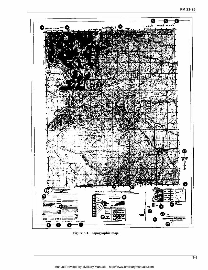
Figure 3-1. Topographic map.
FM 21-26
3-3
Manual Provided by eMilitary Manuals - http://www.emilitarymanuals.com

FM 21-26
u. Grid Reference Box (21). This box is normallylocated in the center of the lower margin. It containsinstructions for composing a grid reference.
v. Unit Imprint and Symbol (22). The unitimprint and symbol is on the left side of the lowermargin. It identifies the agency that prepared andprinted the map with its respective symbol. Thisinformation is important to the map user in evaluatingthe reliability of the map.
w. Legend (23). The legend is located in the lowerleft margin. It illustrates and identifies the topographicsymbols used to depict some of the more prominentfeatures on the map. The symbols are not always thesame on every map. Always refer to the legend to avoiderrors when reading a map.
3-2. ADDITIONAL NOTESNot all maps contain the same items of marginalinformation. Under certain conditions, special notes andscales may be added to aid the map user. The followingare examples:
a. Glossary. This is an explanation of technicalterms or a translation of terms on maps of foreign areaswhere the native language is other than English.
b. Classification. Certain maps require a noteindicating the security classification. This is shown inthe upper and lower margins.
c. Protractor Scale. This scale may appear in theupper margin on some maps. It is used to lay out themagnetic-grid declination for the map which, in turn, isused to orient the map sheet with the aid of the lensaticcompass.
d. Coverage Diagram. On maps at scales of1:100,000 and larger, a coverage diagram may be used.It is normally in the lower or right margin and indicatesthe methods by which the map was made, dates ofphotography, and reliability of the sources. On maps at1:250,000 scale, the coverage diagram is replaced by areliability diagram.
e. Special Notes (24). A special note is anystatement of general information that relates to themapped area. It is normally found in the lower rightmargin. For example: This map is red-light readable.
f. User's Note (25). This note is normally locatedin the lower right-hand margin. It requests cooperationin correcting errors or omissions on the map. Errorsshould be marked and the map forwarded to the agencyidentified in the note.
g. Stock Number Identification (26). All mapspublished by the DMA that are in the Department of theArmy map supply system contain stock numberidentifications that are used in requisitioning mapsupplies. The identification consists of the words"STOCK NO" followed by a unique designation that iscomposed of the series number, the sheet number of the
individual map and, on recently printed sheets, theedition number. The designation is limited to 15 units(letters and numbers). The first 5 units are allotted to theseries number; when the series number is less than 5units, the letter "X" is substituted as the fifth unit. Thesheet number is the next component; however, Romannumerals, which are part of the sheet number, areconverted to Arabic numerals in the stock number. Thelast 2 units are the edition number; the first digit of theedition number is a zero if the number is less than 10. Ifthe current edition number is unknown, the number 01 isused. The latest available edition will be furnished.Asterisks are placed between the sheet number and theedition number when necessary to ensure there are atleast 11 units in the stock number.
h. Conversion Graph (27). Normally found in theright margin, this graph indicates the conversion ofdifferent units of measure used on the map.
3-3. TOPOGRAPHIC MAP SYMBOLSThe purpose of a map is to permit one to visualize anarea of the earth's surface with pertinent features properlypositioned. The map's legend contains the symbols mostcommonly used in a particular series or on that specifictopographic map sheet. Therefore, the legend should bereferred to each time a new map is used. Every effort ismade to design standard symbols that resemble thefeatures they represent. If this is not possible, symbolsare selected that logically imply the features they portray.For example, an open-pit mining operation is representedby a small black drawing of a crossed hammer andpickax.
a. Ideally, all the features within an area wouldappear on a map in their true proportion, position, andshape. This, however, is not practical because many ofthe features would be unimportant and others would beunrecognizable because of their reduction in size.
b. The mapmaker has been forced to use symbolsto represent the natural and man-made features of theearth's surface. These symbols resemble, as closely aspossible, the actual features themselves as viewed fromabove. They are positioned in such a manner that thecenter of the symbol remains in its true location. Anexception to this would be the position of a featureadjacent to a major road. If the width of the road hasbeen exaggerated, then the feature is moved from its trueposition to preserve its relation to the road. Field Manual21-31 gives a description of topographic features andabbreviations authorized for use on our military maps.
3-4. MILITARY SYMBOLSIn addition to the topographic symbols used to representthe natural and man-made features of the earth, militarypersonnel require some method for showing identity,
3-4
Manual Provided by eMilitary Manuals - http://www.emilitarymanuals.com

size, location, or movement of soldiers; and militaryactivities and installations. The symbols used torepresent these military features are known as militarysymbols. These symbols are not normally printed onmaps because the features and units that they representare constantly moving or changing; military security isalso a consideration. They do appear in special mapsand overlays (Chapter 7). The map user draws them in,in accordance with proper security precautions. Refer toFM 101-5-1 for complete information on militarysymbols.
3-5. COLORS USED ON A MILITARY MAPBy the fifteenth century, most European maps werecarefully colored. Profile drawings of mountains andhills were shown in brown, rivers and lakes in blue,vegetation in green, roads in yellow, and specialinformation in red. A look at the legend of a modernmap confirms that the use of colors has not changedmuch over the past several hundred years. To facilitatethe identification of features on a map, the topographicaland cultural information is usually printed in different
colors. These colors may vary from map to map. On astandard large-scale topographic map, the colors usedand the features each represent are:
a. Black. Indicates cultural (man-made) featuressuch as buildings and roads, surveyed spot elevations,and all labels.
b. Red-Brown. The colors red and brown arecombined to identify cultural features, all relief features,non-surveyed spot elevations, and elevation, such ascontour lines on red-light readable maps.
c. Blue. Identifies hydrography or water featuressuch as lakes, swamps, rivers, and drainage.
d. Green. Identifies vegetation with militarysignificance, such as woods, orchards, and vineyards.
e. Brown. Identifies all relief features andelevation, such as contours on older edition maps, andcultivated land on red-light readable maps.
f. Red. Classifies cultural features, such aspopulated areas, main roads, and boundaries, on oldermaps.
g. Other. Occasionally other colors may be usedto show special information. These are indicated in themarginal information as a rule.
FM 21-26
3-5
Manual Provided by eMilitary Manuals - http://www.emilitarymanuals.com

CHAPTER 4
GRIDS
This chapter covers how to determine and report positions on the ground in terms of theirlocations on a map. Knowing where you are (position fixing) and being able to communicatethat knowledge is crucial to successful land navigation as well as to the effective employmentof direct and indirect fire, tactical air support, and medical evacuation. It is essential forvalid target acquisition; accurate reporting of nuclear, biological, and chemical (NBC)contamination and various danger areas; and obtaining emergency resupply. Few factorscontribute as much to the survivability of troops and equipment and to the successfulaccomplishment of a mission as always knowing where you are. The chapter includesexplanations of geographical coordinates, Universal Transverse Mercator grids, the militarygrid reference system, and the use of grid coordinates.
4-1. REFERENCE SYSTEMIn a city, it is quite simple to find a location; the streets arenamed and the buildings have numbers. The only thingneeded is the address. However, finding locations inundeveloped areas or in unfamiliar parts of the world canbe a problem. To cope with this problem, a uniform andprecise system of referencing has been developed.
4-2. GEOGRAPHIC COORDINATESOne of the oldest systematic methods of location is basedupon the geographic coordinate system. By drawing a setof east-west rings around the globe (parallel to the equa-tor), and a set of north-south rings crossing the equator atright angles and converging at the poles, a network ofreference lines is formed from which any point on theearth's surface can be located.
a. The distance of a point north or south of theequator is known as its latitude. The rings around theearth parallel to the equator are called parallels of latitudeor simply parallels. Lines of latitude run east-west butnorth-south distances are measured between them.
b. A second set of rings around the globe at rightangles to lines of latitude and passing through the polesare known as meridians of longitude or simply meridians.One meridian is designated as the prime meridian. Theprime meridian of the system we use runs throughGreenwich, England and is known as the Greenwichmeridian. The distance east or west of a prime meridian toa point is known as its longitude. Lines of longitude(meridians) run north-south but east-west distances aremeasured between them (Figures 4-1 and 4-2).
c. Geographic coordinates are expressed in angularmeasurement. Each circle is divided into 360
Figure 4-1. Prime meridian and equator.
Figure 4-2. Reference lines.
4-1
Manual Provided by eMilitary Manuals - http://www.emilitarymanuals.com

FM 21-26
degrees each degree into 60 minutes, and each minuteinto 60 seconds. The degree is symbolized by °,the minute by ’, and the second by ”. Starting with 0° atthe equator, the parallels of latitude are numbered to 90°both north and south. The extremities are the north pole at90° north latitude and the south pole at 90° south latitude-Latitude can have the same numerical value north orsouth of the equator, so the direction N or S must alwaysbe given. Starting with 0° at the prime meridian,longitude is measured both east and west around theworld. Lines east of the prime meridian are numbered to180° and identified as east longitude; lines west of theprime meridian are numbered to 180° and identified aswest longitude. The direction E or W must always hegiven. The line directly opposite the prime meridian,180°, may be referred to as either east or west longitude.The values of geographic coordinates, being in units ofangular measure, will mean more if they are comparedwith units of measure with which we are more familiar.At any point on the earth, the ground distance covered byone degree of latitude is about 111 kilometers (69 miles);one second is equal to about 30 meters (100 feet). Theground distance covered by one degree of longitude at theequator is also about 111 kilometers, but decreases as onemoves north or south, until it becomes zero at the poles.For example, one second of longitude represents about 30meters (100 feet) at the equator; but at the latitude ofWashington, DC, one second of longitude isapproximately 24 meters (78 feet). Latitude and longitudeare illustrated in Figure 4-3.
Figure 4-3. Latitude and longitude.
d. Geographic coordinates appear on all standardmilitary maps; on some they may be the only method oflocating and referencing the location of a point. The fourlines that enclose the body of the map (neatlines) arelatitude and longitude lines. Their values are given indegrees and minutes at each of the four corners. Ona portion of the Columbus map (Figure 4-4), the figures
32°15’ and 84°45’ appear at the lower right corner. Thebottom line of this map is latitude 32°15’00”N, and theline running up the right side is longitude 84°45’00”W.In addition to the latitude and longitude given for the fourcorners, there are, at regularly spaced intervals along thesides of the map, small tick marks extending into the bodyof the map. Each of these tick marks is identified by itslatitude or longitude value. Near the top of the right sideof the map is a tick mark and the number 20’. The fullvalue for this tick marks is 32°20’00” of latitude. Atone-third and two-thirds of the distance across the mapfrom the 20’ tick mark will be found a cross tick mark(grid squares 0379 and 9679) and at the far side another20’ tick mark. By connecting the tick marks and crosseswith straight lines, a 32°20’00” line of latitude can beadded to the map. This procedure is also used to locate the32°25’00” line of latitude. For lines of longitude, the sameprocedure is followed using the tick marks along the topand bottom edges of the map.
e. After the parallels and meridians have been drawn,the geographic interval (angular distance between twoadjacent lines) must be determined. Examination of thevalues given at the tick marks gives the interval. For mostmaps of scale 1:25,000, the interval is 2’30”. For theColumbus map and most maps of scale 1:50,000, it is5’00”. The geographic coordinates of a point are found bydividing the sides of the geographic square in which thepoint is located into the required number of equal parts. Ifthe geographic interval is 5’00 and the location of a pointis required to the nearest second, each side of thegeographic square must be divided into 300 equal parts(5’00” = 300”), each of which would have a value of onesecond. Any scale or ruler that has 300 equal divisionsand is as long as or longer than the spacing between thelines may be used.
f. The following steps will determine the geographiccoordinates of Wilkinson Cemetery (northwest of the townof Cusseta) on the Columbus map.
(1) Draw the parallels and meridians on the map thatenclose the area around the cemetery.
(2) Determine the values of the parallels and me-ridians where the point falls.
Latitude 32°15’00” and 32°20’00”.Longitude 84°45’00” and 84050100”.
(3) Determine the geographic interval (5’00” = 300”).
(4) Select a scale that has 300 small divisions ormultiples thereof (300 divisions, one second each; 150divisions, two seconds each; 75 divisions, four secondseach, and so forth).
4 -2
Manual Provided by eMilitary Manuals - http://www.emilitarymanuals.com
FM 21-26
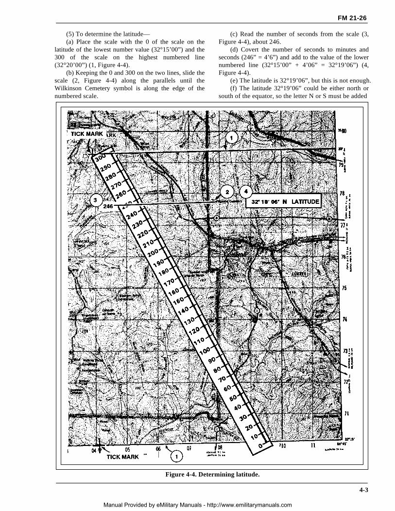
(5) To determine the latitude—(a) Place the scale with the 0 of the scale on the
latitude of the lowest number value (32°15’00”) and the300 of the scale on the highest numbered line(32°20’00”) (1, Figure 4-4).
(b) Keeping the 0 and 300 on the two lines, slide thescale (2, Figure 4-4) along the parallels until theWilkinson Cemetery symbol is along the edge of thenumbered scale.
(c) Read the number of seconds from the scale (3,Figure 4-4), about 246.
(d) Covert the number of seconds to minutes andseconds (246” = 4’6”) and add to the value of the lowernumbered line (32°15’00” + 4’06” = 32°19’06”) (4,Figure 4-4).
(e) The latitude is 32°19’06”, but this is not enough.(f) The latitude 32°19’06” could be either north or
south of the equator, so the letter N or S must be added
Figure 4-4. Determining latitude.
4-3
Manual Provided by eMilitary Manuals - http://www.emilitarymanuals.com

FM 21-26
to the latitude. To determine whether it is N or S, look atthe latitude values at the edge of the map and find thedirection in which they become larger. If they are largergoing north, use N; if they are larger going south, use S.
(g) The latitude for the cemetery is 32°19’06”N.
(6) To determine the longitude, repeat the samesteps but measure between lines of longitude and use Eand W. The geographic coordinates of WilkinsonCemetery should be about 32°19’06”N and 84°47’32”W(Figure 4-5).
Figure 4-5. Determining longitude.
4-4
Manual Provided by eMilitary Manuals - http://www.emilitarymanuals.com