Manufacturing Technology II Exercise 2 Powder Metallurgy€¦ · Manufacturing Technology II...
17
Lehrstuhl für Technologie der Fertigungsverfahren Laboratorium für Werkzeugmaschinen und Betriebslehre Manufacturing Technology II Exercise 2 Powder Metallurgy Werkzeugmaschinenlabor Lehrstuhl für Technologie der Fertigungsverfahren Prof. Dr. - Ing. F. Klocke RWTH - Aachen Steinbachstraße 53 52065 Aachen
Transcript of Manufacturing Technology II Exercise 2 Powder Metallurgy€¦ · Manufacturing Technology II...

Lehrstuhl für Technologieder Fertigungsverfahren
Laboratoriumfür Werkzeugmaschinenund Betriebslehre
Manufacturing Technology II
Exercise 2
Powder Metallurgy
WerkzeugmaschinenlaborLehrstuhl für
Technologie der FertigungsverfahrenProf. Dr. - Ing. F. Klocke
RWTH - AachenSteinbachstraße 53
52065 Aachen
Inhaltsverzeichnis
Fertigungstechnik II - Übung 2 2
Table of Contents1 Introduction .................................................................................................... 3
2 Technology and design related parameters................................................... 42.1 Potential and limitations of powder metallurgy............................................... 42.2 Sintering-oriented design ............................................................................... 6
3 Economic parameters .................................................................................... 9
4 Film: Steps in the operation and exemplar applications............................... 12
5 Tasks ........................................................................................................... 135.1 Tool design................................................................................................... 135.2 Manufacturing a sintered connecting rod ..................................................... 145.3 Manufacturing a sintered bronze shell ......................................................... 15
Einleitung
Fertigungstechnik II - Übung 2 3
1 Introduction
Powder metallurgy encompasses the manufacture of metallic powder and the
production of parts made from this powder by forming and sintering. The term
Sintering is used to describe the heat treatment of powder or of a compact at
temperatures below the melting point of the base material. The term Sinteringtechnology encompasses all of the steps involved in the operation to
manufacture a sintered part, with the exception of powder production.
There are certain materials which can only be produced in a powder metallurgical
operation, e.g. hard metals or alloys of metals with widely differing melting points.
The technological potential and limitations of powder metallurgy will be explained
in the first part of the exercise.
The limitations of powder metallurgy stem partly from geometric boundary
condition. The guidelines for sintering-oriented design are presented as a further
focus of this exercise.
Powder metallurgy competes with casting processes, solid forming and cutting
techniques in a number of applications. The decision in favour of powder
metallurgy, is therefore based not only on technological criteria. In fact, the
economic parameters are frequently the decisive factor.
The steps in the powder metallurgy will be shown in a short film along with typical
sintered parts within the framework of this exercise.
To conclude, the basic principles of sintering oriented design of pressing tools and
sintered parts will be examined in detail.

Technologische und konstruktive Randbedingungen
Fertigungstechnik II - Übung 2 4
2 Technology and design related parameters
2.1 Potential and limitations of powder metallurgy
Powder metallurgy offers possibilities in terms of material composition which are
either completely impossible when casting techniques are used or which can be
achieved only with considerable work and at great expense.
Suitability for metallic and non-metallic materials- combinations are also possible (Example: Cermets)
Manufacture of defined material combinations- Time-consuming and expensive via the casting process
- Example: High-purity metals, super-alloys
- Examples: Tungsten, molybdenum, tantalum, niobium
Manufacture of refractory metals- Cannot be produced using casting technology
Manufacture of metals with a wide variance in melting points- Manufacture by sintering with a liquid phase or via subsequent infiltration
- Example: tungsten-copper or molybdenum-silver switching contacts
Manufacture of materials with hard materials in a ductile matrix- Examples: Hard metals, stellites, high-speed metals
Regulating a controlled pore space- Disadvantage: 100% density impossible to achieve using sintering
technology
- Infiltrating with plastic or metal which has a low melting point:
Impermeable to oil and water
- Filling the pore space with oil: Lubricating sliding bearings
- Examples of highly porous parts: Filters, chokes, flame arresters
Technologische und konstruktive Randbedingungen
Fertigungstechnik II - Übung 2 5
The structure of parts produced using a powder-metallurgical process, has a high
level of homogeneity and isotropy. The directed fibre orientation seen in forged or
rolled parts, does not exist.
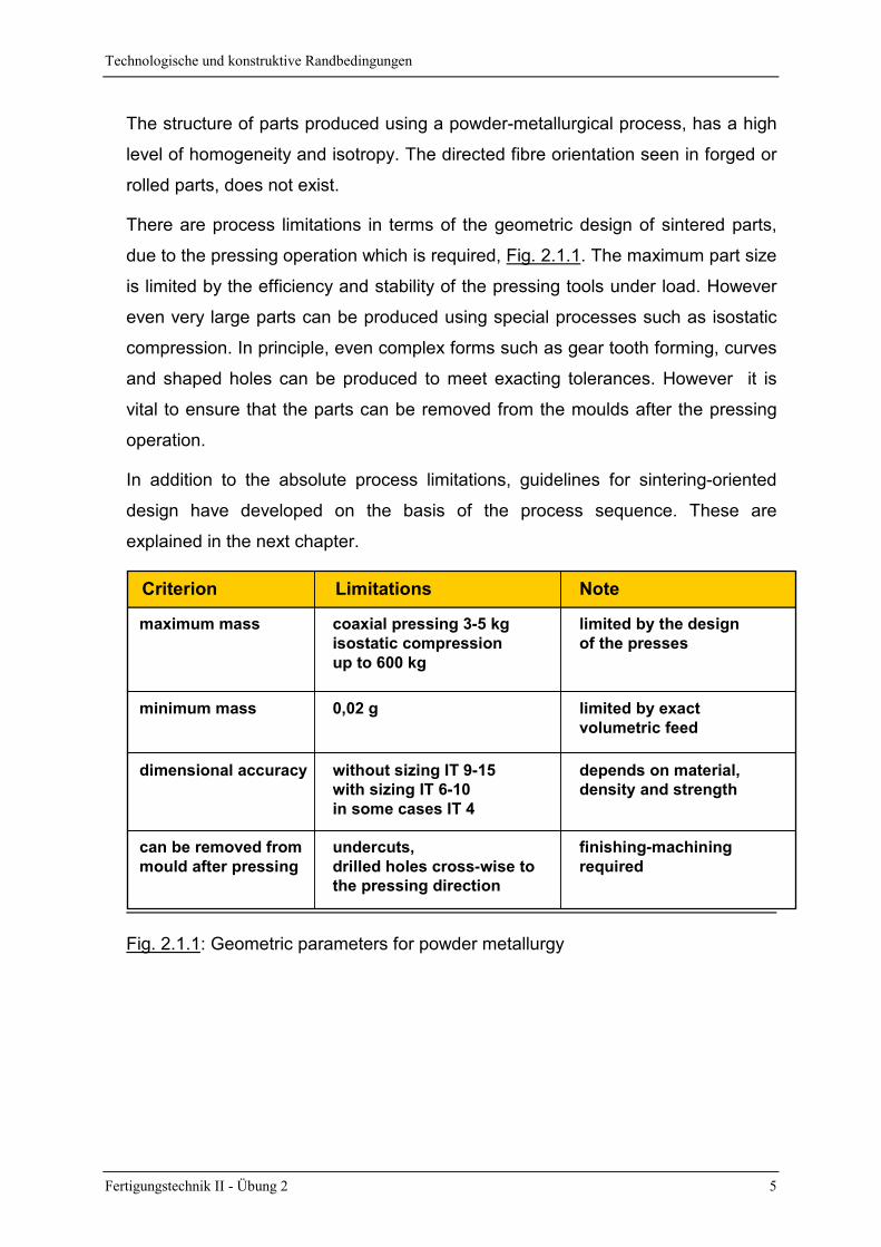
There are process limitations in terms of the geometric design of sintered parts,
due to the pressing operation which is required, Fig. 2.1.1. The maximum part size
is limited by the efficiency and stability of the pressing tools under load. However
even very large parts can be produced using special processes such as isostatic
compression. In principle, even complex forms such as gear tooth forming, curves
and shaped holes can be produced to meet exacting tolerances. However it is
vital to ensure that the parts can be removed from the moulds after the pressing
operation.
In addition to the absolute process limitations, guidelines for sintering-oriented
design have developed on the basis of the process sequence. These are
explained in the next chapter.
Criterion Limitations Note
maximum mass coaxial pressing 3-5 kgisostatic compressionup to 600 kg
limited by the designof the presses
minimum mass 0,02 g limited by exact volumetric feed
dimensional accuracy without sizing IT 9-15with sizing IT 6-10in some cases IT 4
depends on material,density and strength
can be removed frommould after pressing
undercuts,drilled holes cross-wise tothe pressing direction
finishing-machiningrequired
Fig. 2.1.1: Geometric parameters for powder metallurgy
Technologische und konstruktive Randbedingungen
Fertigungstechnik II - Übung 2 6
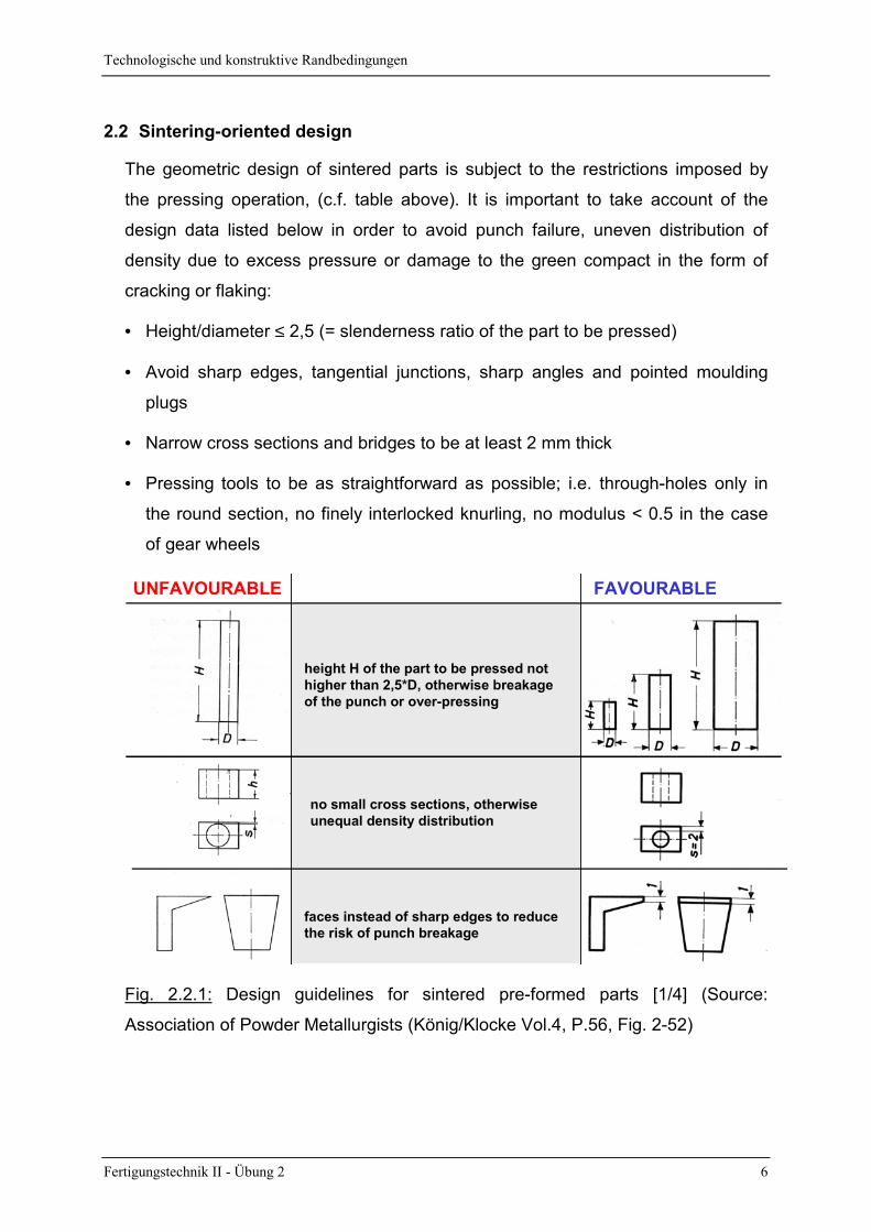
2.2 Sintering-oriented design
The geometric design of sintered parts is subject to the restrictions imposed by
the pressing operation, (c.f. table above). It is important to take account of the
design data listed below in order to avoid punch failure, uneven distribution of
density due to excess pressure or damage to the green compact in the form of
cracking or flaking:
• Height/diameter ≤ 2,5 (= slenderness ratio of the part to be pressed)
• Avoid sharp edges, tangential junctions, sharp angles and pointed moulding
plugs
• Narrow cross sections and bridges to be at least 2 mm thick
• Pressing tools to be as straightforward as possible; i.e. through-holes only in
the round section, no finely interlocked knurling, no modulus < 0.5 in the case
of gear wheels
UNFAVOURABLE FAVOURABLE
height H of the part to be pressed nothigher than 2,5*D, otherwise breakageof the punch or over-pressing
no small cross sections, otherwiseunequal density distribution
faces instead of sharp edges to reducethe risk of punch breakage
Fig. 2.2.1: Design guidelines for sintered pre-formed parts [1/4] (Source:
Association of Powder Metallurgists (König/Klocke Vol.4, P.56, Fig. 2-52)
Technologische und konstruktive Randbedingungen
Fertigungstechnik II - Übung 2 7
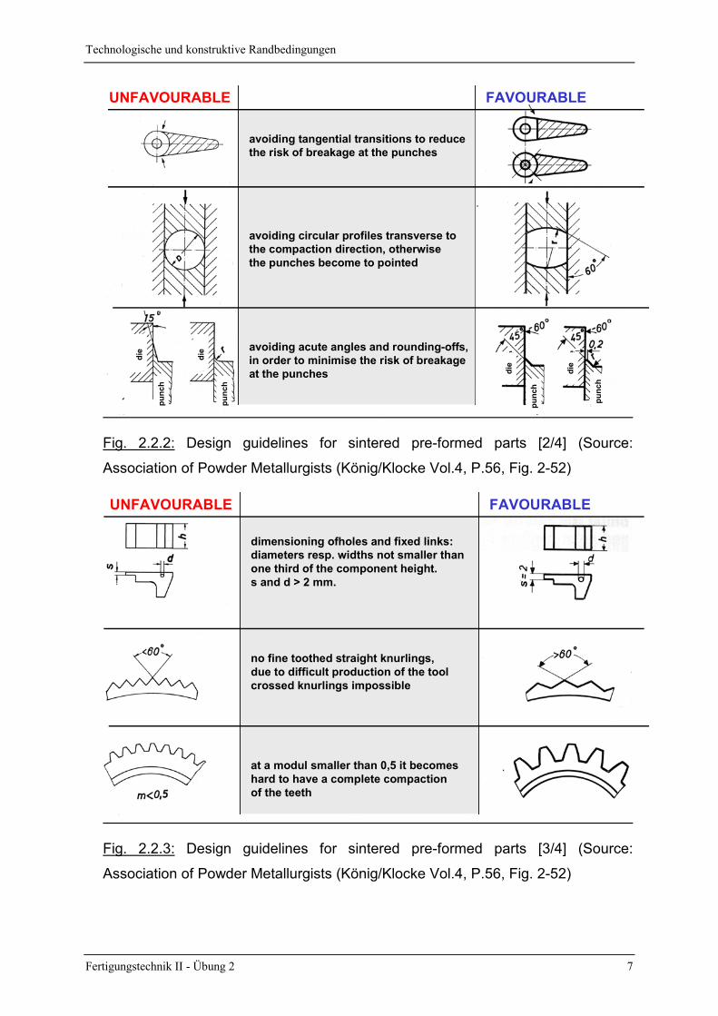
avoiding tangential transitions to reducethe risk of breakage at the punches
avoiding acute angles and rounding-offs,in order to minimise the risk of breakageat the punches
avoiding circular profiles transverse to the compaction direction, otherwisethe punches become to pointed
UNFAVOURABLE FAVOURABLE
punc
h
die
die
punc
h
punc
h
die
die
punc
h
Fig. 2.2.2: Design guidelines for sintered pre-formed parts [2/4] (Source:
Association of Powder Metallurgists (König/Klocke Vol.4, P.56, Fig. 2-52)
dimensioning ofholes and fixed links:diameters resp. widths not smaller thanone third of the component height.s and d > 2 mm.
no fine toothed straight knurlings, due to difficult production of the tool crossed knurlings impossible
at a modul smaller than 0,5 it becomeshard to have a complete compaction of the teeth
UNFAVOURABLE FAVOURABLE
Fig. 2.2.3: Design guidelines for sintered pre-formed parts [3/4] (Source:
Association of Powder Metallurgists (König/Klocke Vol.4, P.56, Fig. 2-52)

Technologische und konstruktive Randbedingungen
Fertigungstechnik II - Übung 2 8
bigger distance between the bottomof the tooth space and the internal bore,risk for punches
breaking througs if possible rounded,otherwise the tools become expensive
diameter tolerances not smaller thanIT 7, height tolerances not smaller thanIT 12.
UNFAVOURABLE FAVOURABLE
Fig. 2.2.4: Design guidelines for sintered pre-formed parts [4/4] (Source:
Association of Powder Metallurgists (König/Klocke Vol.4, P.56, Fig. 2-52)
Wirtschaftliche Randbedingungen
Fertigungstechnik II - Übung 2 9
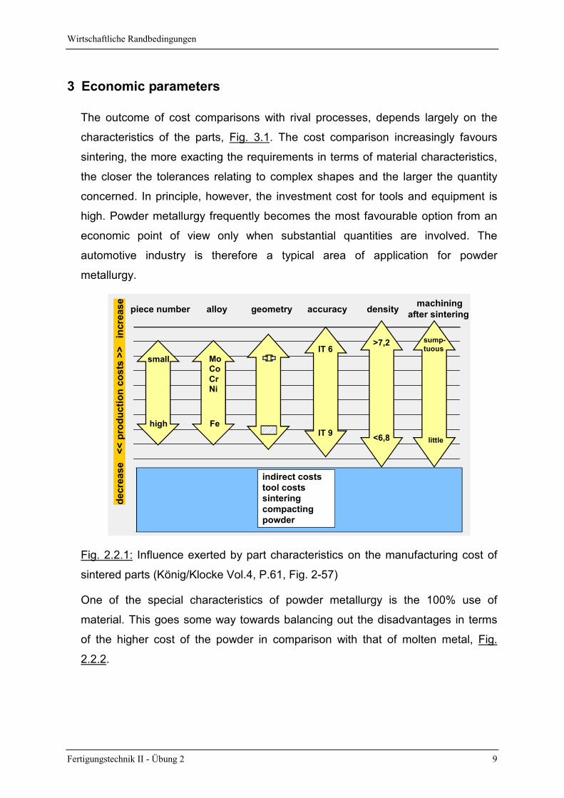
3 Economic parameters
The outcome of cost comparisons with rival processes, depends largely on the
characteristics of the parts, Fig. 3.1. The cost comparison increasingly favours
sintering, the more exacting the requirements in terms of material characteristics,
the closer the tolerances relating to complex shapes and the larger the quantity
concerned. In principle, however, the investment cost for tools and equipment is
high. Powder metallurgy frequently becomes the most favourable option from an
economic point of view only when substantial quantities are involved. The
automotive industry is therefore a typical area of application for powder
metallurgy.
piece number alloy geometry accuracy machining
after sintering
decr
ease
<<
pro
duct
ion
cost
s >>
in
crea
se
indirect coststool costssinteringcompactingpowder
>7,2
density
<6,8
small
high
MoCoCrNi
Fe
IT 6
IT 9
sump-tuous
little
Fig. 2.2.1: Influence exerted by part characteristics on the manufacturing cost of
sintered parts (König/Klocke Vol.4, P.61, Fig. 2-57)
One of the special characteristics of powder metallurgy is the 100% use of
material. This goes some way towards balancing out the disadvantages in terms
of the higher cost of the powder in comparison with that of molten metal, Fig.
2.2.2.
Wirtschaftliche Randbedingungen
Fertigungstechnik II - Übung 2 10
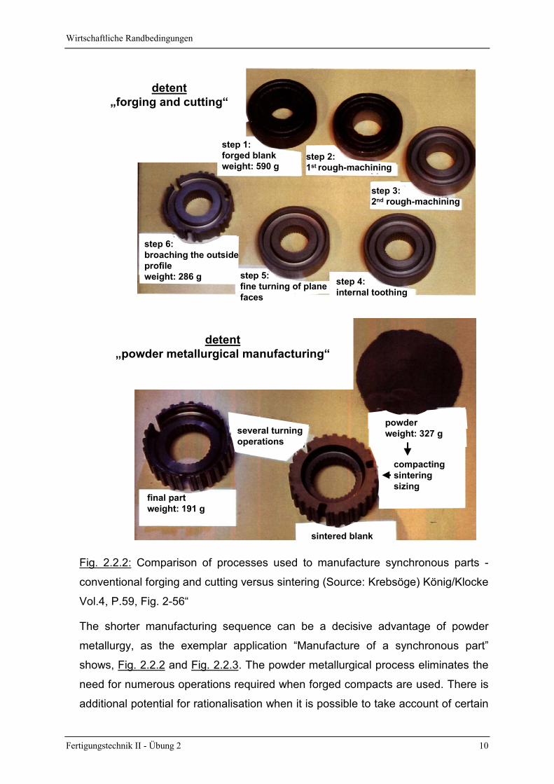
step 3:2nd rough-machining
step 2:1st rough-machining
step 4:internal toothing
step 5:fine turning of planefaces
step 6:broaching the outsideprofileweight: 286 g
detent„forging and cutting“
step 1:forged blankweight: 590 g
detent„powder metallurgical manufacturing“
final partweight: 191 g
several turningoperations
sintered blank
powderweight: 327 g
compactingsinteringsizing
Fig. 2.2.2: Comparison of processes used to manufacture synchronous parts -
conventional forging and cutting versus sintering (Source: Krebsöge) König/Klocke
Vol.4, P.59, Fig. 2-56“
The shorter manufacturing sequence can be a decisive advantage of powder
metallurgy, as the exemplar application “Manufacture of a synchronous part”
shows, Fig. 2.2.2 and Fig. 2.2.3. The powder metallurgical process eliminates the
need for numerous operations required when forged compacts are used. There is
additional potential for rationalisation when it is possible to take account of certain
Wirtschaftliche Randbedingungen
Fertigungstechnik II - Übung 2 11
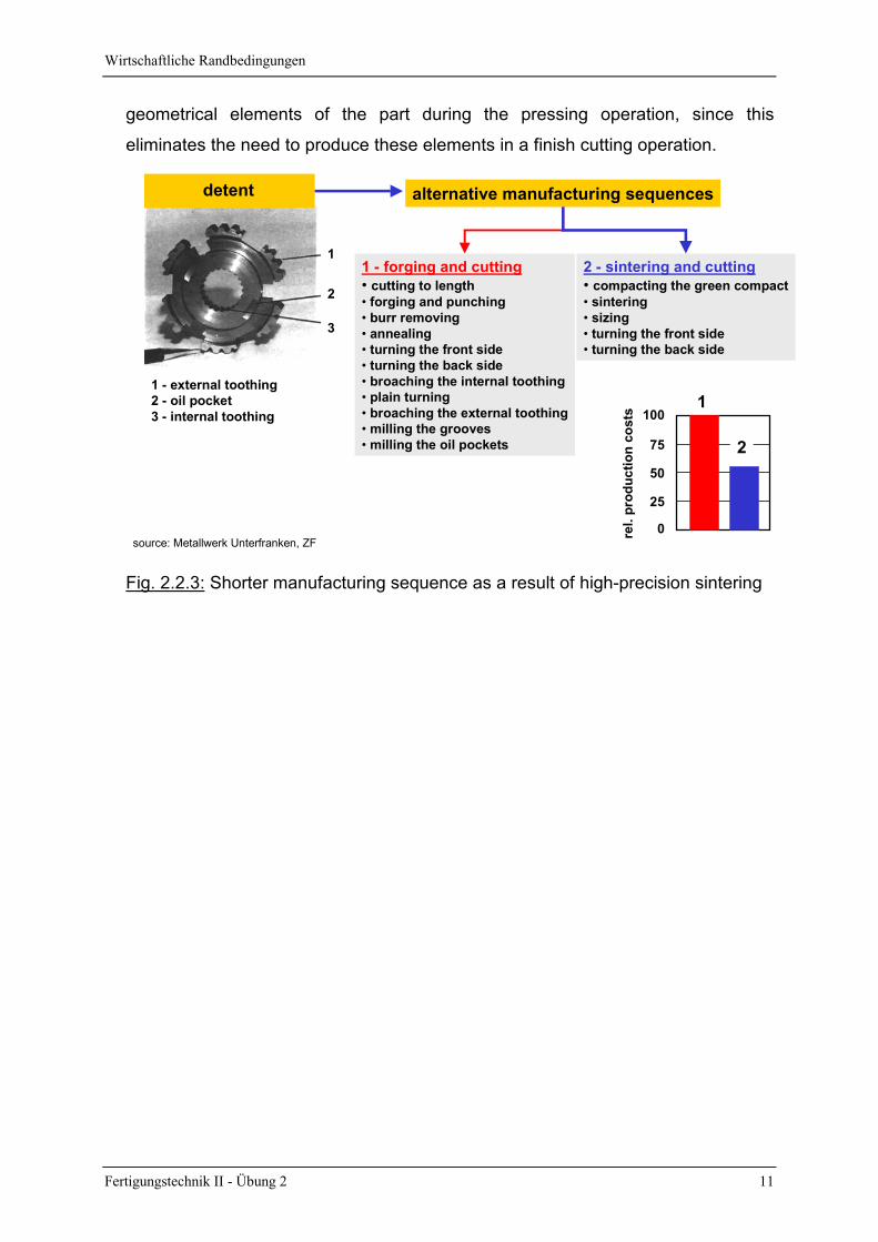
geometrical elements of the part during the pressing operation, since this
eliminates the need to produce these elements in a finish cutting operation.
source: Metallwerk Unterfranken, ZF
1 - forging and cutting• cutting to length• forging and punching• burr removing• annealing• turning the front side• turning the back side• broaching the internal toothing• plain turning• broaching the external toothing• milling the grooves• milling the oil pockets
alternative manufacturing sequences
2 - sintering and cutting• compacting the green compact• sintering• sizing• turning the front side• turning the back side
1 - external toothing2 - oil pocket3 - internal toothing
1
2
3
detent
1
2
0
25
50
75
100
rel.
prod
uctio
n co
sts
Fig. 2.2.3: Shorter manufacturing sequence as a result of high-precision sintering

Film: Verfahrensschritte und Anwendungsbeispiele
Fertigungstechnik II - Übung 2 12
4 Film: Steps in the operation and exemplar applications
Notes:
Übungsaufgaben
Fertigungstechnik II - Übung 2 13
5 Tasks
5.1 Tool design
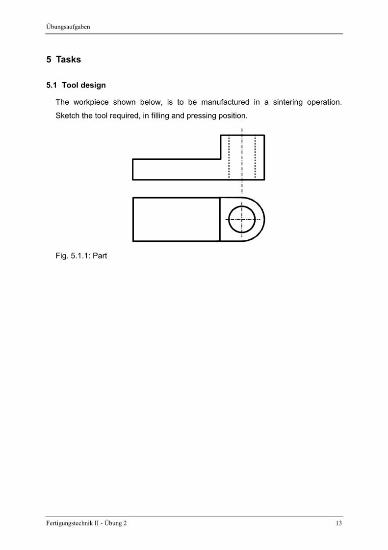
The workpiece shown below, is to be manufactured in a sintering operation.
Sketch the tool required, in filling and pressing position.
Fig. 5.1.1: Part
Übungsaufgaben
Fertigungstechnik II - Übung 2 14
5.2 Manufacturing a sintered connecting rod
A forged connecting rod is to be replaced by a sintered connecting rod with the
same dimensions. The sintered connecting rod weights 576 g and is 24 g lighter
than the forged one.
a) Calculate the porosity P and name the special operation required in order to
manufacture sintered parts with this level of porosity.
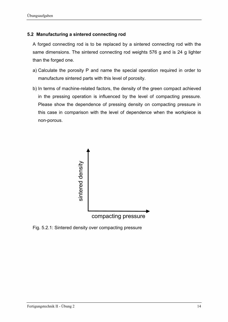
b) In terms of machine-related factors, the density of the green compact achieved
in the pressing operation is influenced by the level of compacting pressure.
Please show the dependence of pressing density on compacting pressure in
this case in comparison with the level of dependence when the workpiece is
non-porous.
compacting pressure
sint
ered
den
sity
Fig. 5.2.1: Sintered density over compacting pressure
Übungsaufgaben
Fertigungstechnik II - Übung 2 15
5.3 Manufacturing a sintered bronze shell
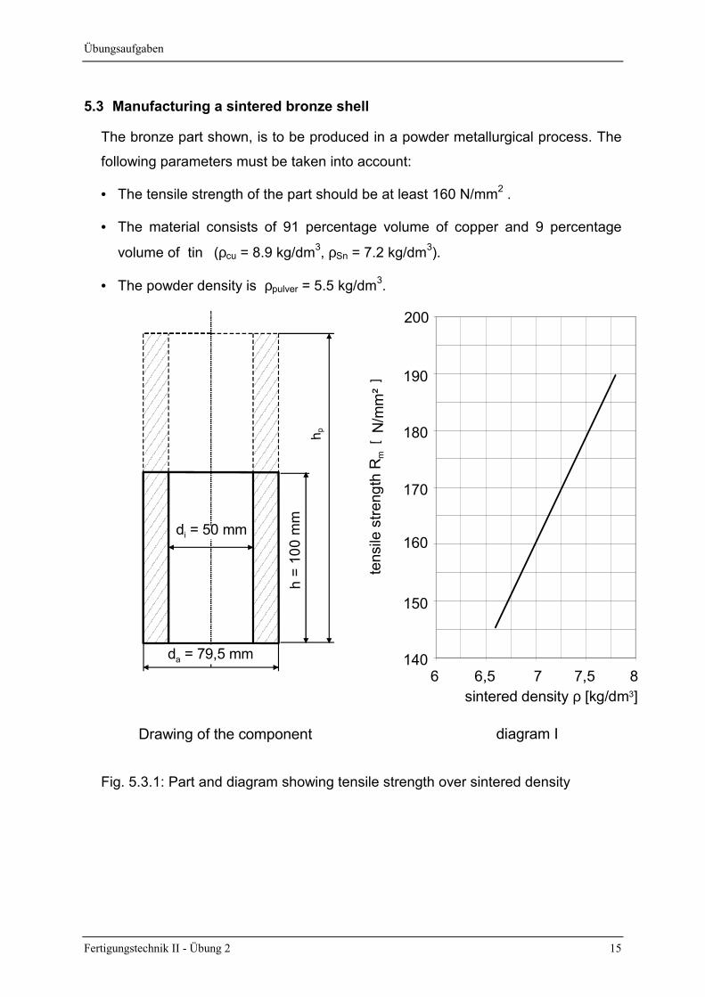
The bronze part shown, is to be produced in a powder metallurgical process. The
following parameters must be taken into account:
• The tensile strength of the part should be at least 160 N/mm2 .
• The material consists of 91 percentage volume of copper and 9 percentage
volume of tin (ρcu = 8.9 kg/dm3, ρSn = 7.2 kg/dm3).
• The powder density is ρpulver = 5.5 kg/dm3.h
= 10
0 m
mh p
di = 50 mm
da = 79,5 mm 140
150
160
170
180
190
6 6,5 7 7,5 8sintered density ρ [kg/dm3]
tens
ile s
treng
th R
mN
/ mm
²
200
[
]
Drawing of the component diagram I
Fig. 5.3.1: Part and diagram showing tensile strength over sintered density
Übungsaufgaben
Fertigungstechnik II - Übung 2 16
a) Calculate the porosity P, of the workpiece to be produced, taking account of the
part characteristics which are required.
b) Determine the height of the layer of powder hp before pressing.
Übungsaufgaben
Fertigungstechnik II - Übung 2 17
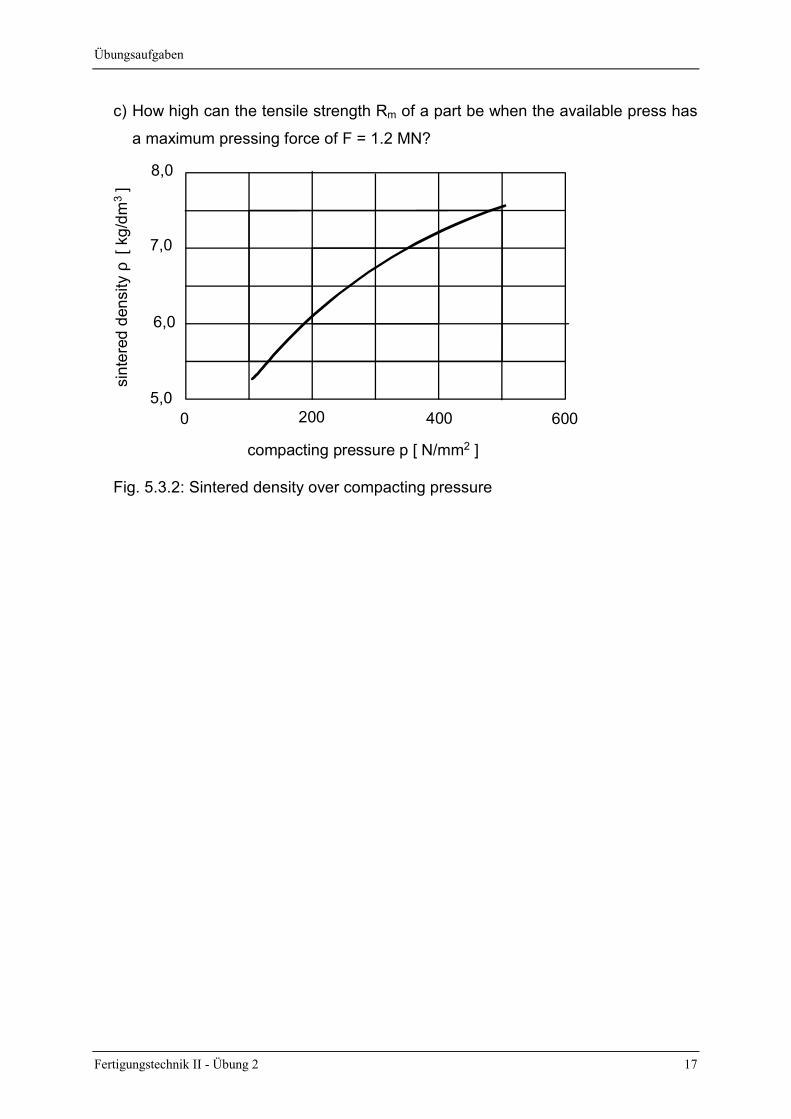
c) How high can the tensile strength Rm of a part be when the available press has
a maximum pressing force of F = 1.2 MN?
8,0
7,0
6,0
5,00 200 400 600
sint
ered
den
sity
ρ [
kg/
dm3 ]
compacting pressure p [ N/mm2 ]
Fig. 5.3.2: Sintered density over compacting pressure