manufacturing hydrogen fuelling stations · manufacturing hydrogen fuelling stations ... Content...
24
From prototype to serial production manufacturing hydrogen fuelling stations DI Markus Mayer A3PS Conference 2014
Transcript of manufacturing hydrogen fuelling stations · manufacturing hydrogen fuelling stations ... Content...
From prototype to serial
production
manufacturing hydrogen
fuelling stations
DI Markus Mayer
A3PS Conference 2014
2
Cryogenic piston pump
Content
Technology development
Linde small serial production of hydrogen fuelling stations
Linde hydrogen refuelling systems
Linde Vienna – ATZ
3
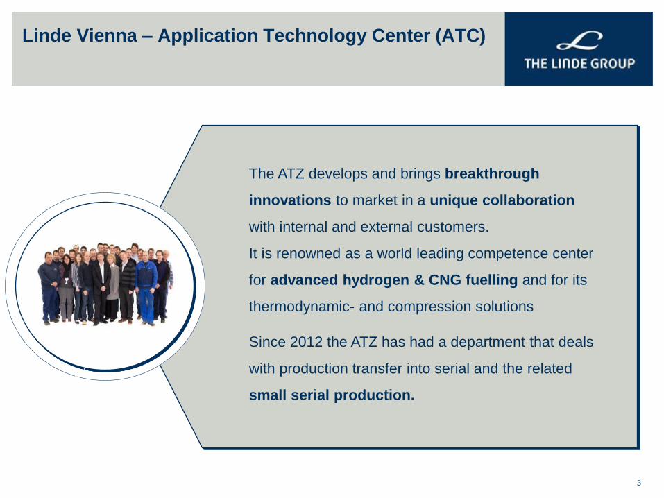
The ATZ develops and brings breakthrough
innovations to market in a unique collaboration
with internal and external customers.
It is renowned as a world leading competence center
for advanced hydrogen & CNG fuelling and for its
thermodynamic- and compression solutions
Since 2012 the ATZ has had a department that deals
with production transfer into serial and the related
small serial production.
Linde Vienna – Application Technology Center (ATC)
4
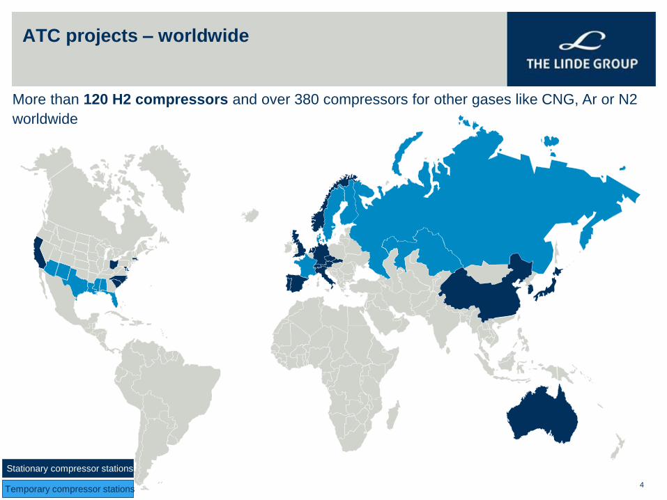
ATC projects – worldwide
More than 120 H2 compressors and over 380 compressors for other gases like CNG, Ar or N2
worldwide
Temporary compressor stations
Stationary compressor stations
5
Cryogenic piston pump
Content
Technology development
Linde small serial production of hydrogen fuelling stations
Linde hydrogen refuelling systems
Linde Vienna – ATZ
6
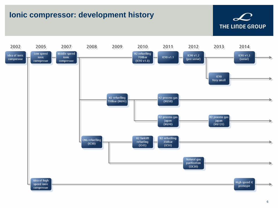
Discussion Outline Ionic compressor: development history
7
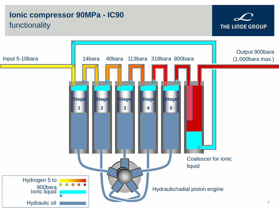
Ionic compressor 90MPa - IC90
functionality
Stage
1
Stage
2
Stage
3
Stage
4
Stage
5
Output 900bara
(1.000bara max.) Input 5-10bara
Coalescer for ionic
liquid
14bara 40bara 113bara 318bara 900bara
Hydrogen 5 to
900bara Ionic liquid
Hydraulic oil
Hydraulic/radial piston engine
8
Cryogenic piston pump
Content
Technology development
Linde small serial production of hydrogen fuelling stations
Linde hydrogen refuelling systems
Linde Vienna – ATZ
9
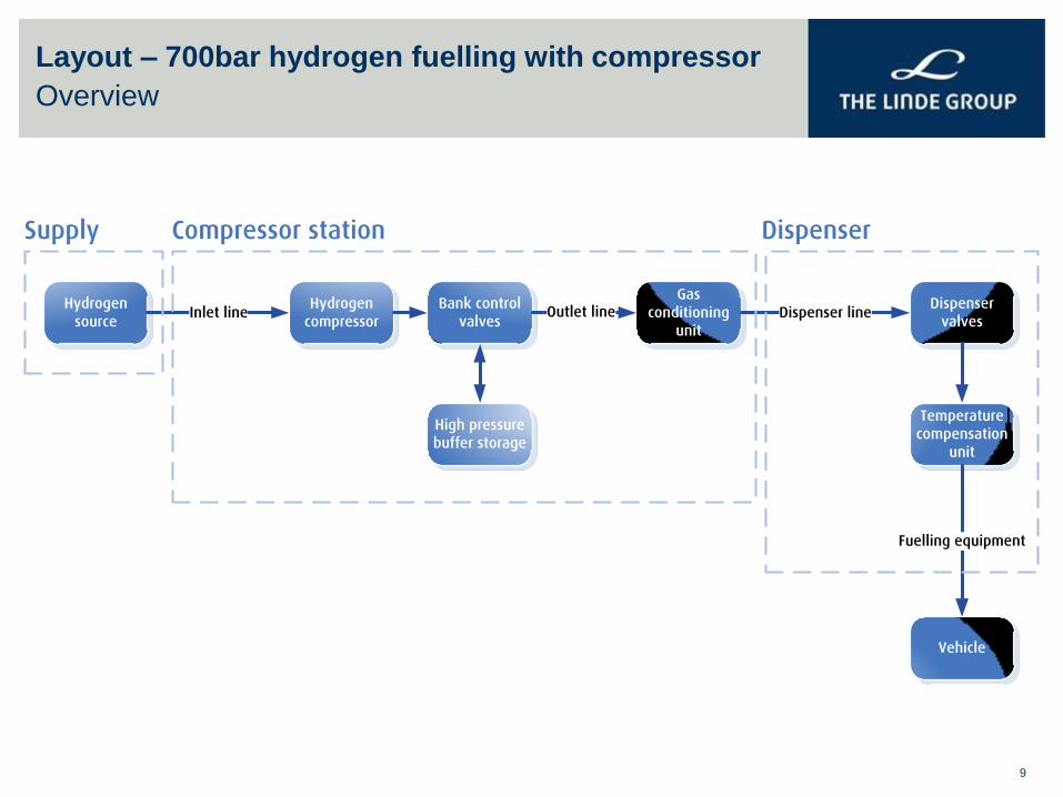
Layout – 700bar hydrogen fuelling with compressor
Overview
Hydrogen
sourceInlet line
Hydrogen
compressor
Bank control
valves
High pressure
buffer storage
Gas
conditioning
unit
Dispenser
valves
Temperature
compensation
unit
Outlet line Dispenser line
Fuelling equipment
Vehicle
Supply Compressor station Dispenser
10
Basic layout
Hydrogen source
Hydrogen
source
Inlet line
Hydrogen
compressor
Bank control
valves
High pressure
buffer storage
Gas
conditioning
unit
Dispenser
valves
Temperature
compensation
unit
Outlet line
Dispenser line
Fuelling equipment
Vehicle
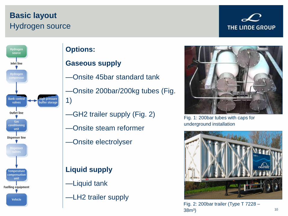
Options:
Gaseous supply
—Onsite 45bar standard tank
—Onsite 200bar/200kg tubes (Fig.
1)
—GH2 trailer supply (Fig. 2)
—Onsite steam reformer
—Onsite electrolyser
Liquid supply
—Liquid tank
—LH2 trailer supply
Fig. 1: 200bar tubes with caps for
underground installation
Fig. 2: 200bar trailer (Type T 7228 –
38m³)
11
Basic layout
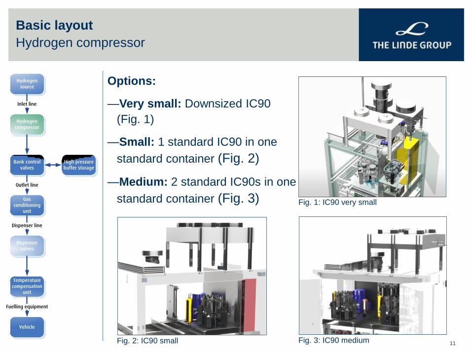
Hydrogen compressor
Options:
—Very small: Downsized IC90
(Fig. 1)
—Small: 1 standard IC90 in one
standard container (Fig. 2)
—Medium: 2 standard IC90s in one
standard container (Fig. 3)
Fig. 2: IC90 small
Fig. 1: IC90 very small
Fig. 3: IC90 medium
Hydrogen
source
Inlet line
Hydrogen
compressor
Bank control
valves
High pressure
buffer storage
Gas
conditioning
unit
Dispenser
valves
Temperature
compensation
unit
Outlet line
Dispenser line
Fuelling equipment
Vehicle
12
Basic layout
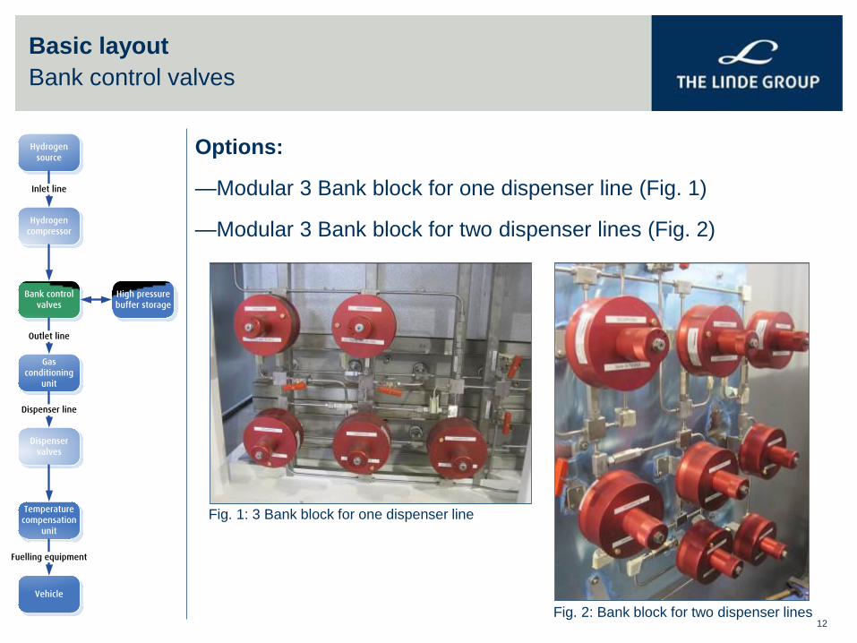
Bank control valves
Options:
—Modular 3 Bank block for one dispenser line (Fig. 1)
—Modular 3 Bank block for two dispenser lines (Fig. 2)
Fig. 1: 3 Bank block for one dispenser line
Fig. 2: Bank block for two dispenser lines
Hydrogen
source
Inlet line
Hydrogen
compressor
Bank control
valves
High pressure
buffer storage
Gas
conditioning
unit
Dispenser
valves
Temperature
compensation
unit
Outlet line
Dispenser line
Fuelling equipment
Vehicle
13
Basic layout
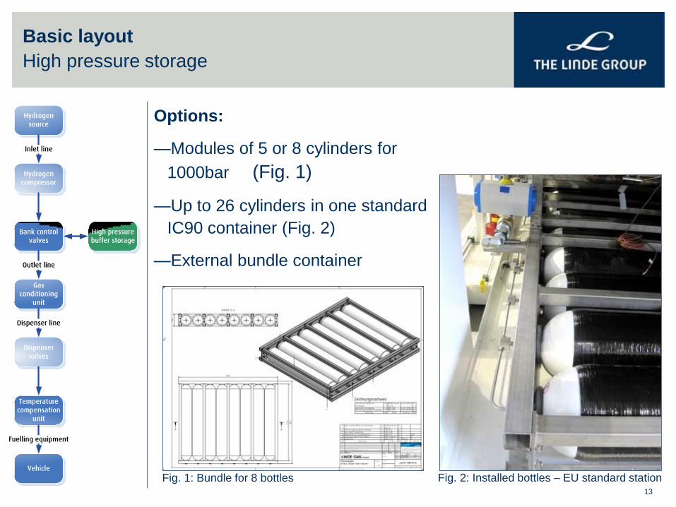
High pressure storage
Options:
—Modules of 5 or 8 cylinders for
1000bar (Fig. 1)
—Up to 26 cylinders in one standard
IC90 container (Fig. 2)
—External bundle container
Fig. 1: Bundle for 8 bottles Fig. 2: Installed bottles – EU standard station
Hydrogen
source
Inlet line
Hydrogen
compressor
Bank control
valves
High pressure
buffer storage
Gas
conditioning
unit
Dispenser
valves
Temperature
compensation
unit
Outlet line
Dispenser line
Fuelling equipment
Vehicle
14
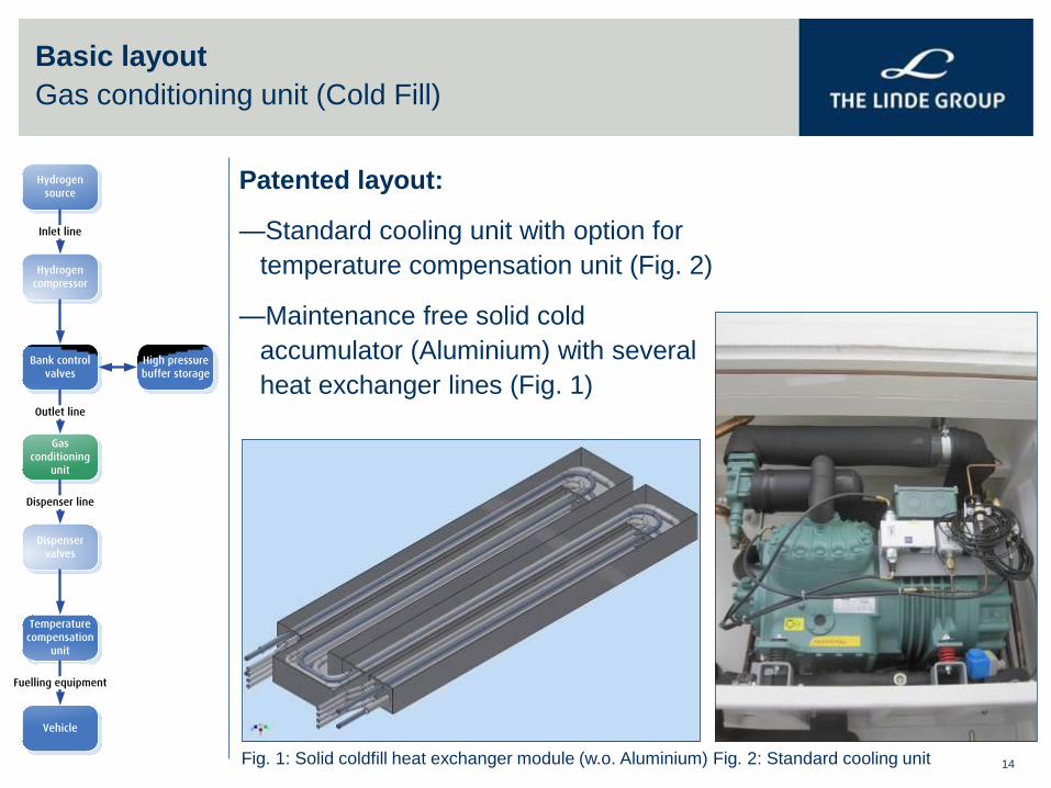
Basic layout
Gas conditioning unit (Cold Fill)
Patented layout:
—Standard cooling unit with option for
temperature compensation unit (Fig. 2)
—Maintenance free solid cold
accumulator (Aluminium) with several
heat exchanger lines (Fig. 1)
Fig. 1: Solid coldfill heat exchanger module (w.o. Aluminium) Fig. 2: Standard cooling unit
Hydrogen
source
Inlet line
Hydrogen
compressor
Bank control
valves
High pressure
buffer storage
Gas
conditioning
unit
Dispenser
valves
Temperature
compensation
unit
Outlet line
Dispenser line
Fuelling equipment
Vehicle
15
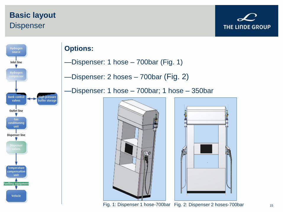
Basic layout
Dispenser
Options:
—Dispenser: 1 hose – 700bar (Fig. 1)
—Dispenser: 2 hoses – 700bar (Fig. 2)
—Dispenser: 1 hose – 700bar; 1 hose – 350bar
Fig. 1: Dispenser 1 hose-700bar Fig. 2: Dispenser 2 hoses-700bar
Hydrogen
source
Inlet line
Hydrogen
compressor
Bank control
valves
High pressure
buffer storage
Gas
conditioning
unit
Dispenser
valves
Temperature
compensation
unit
Outlet line
Dispenser line
Fuelling equipment
Vehicle
16
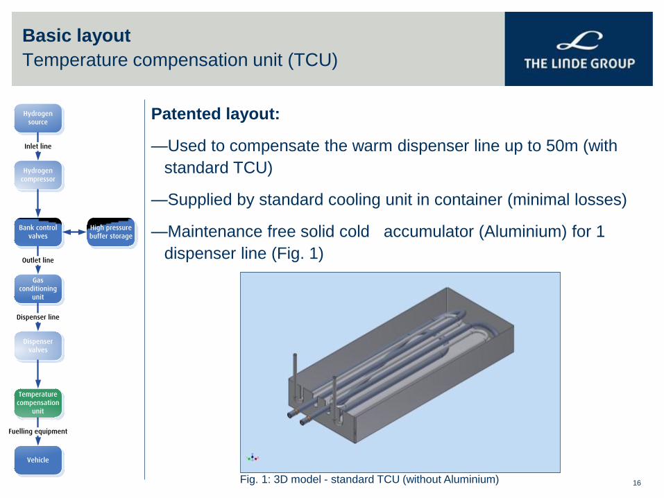
Basic layout
Temperature compensation unit (TCU)
Patented layout:
—Used to compensate the warm dispenser line up to 50m (with
standard TCU)
—Supplied by standard cooling unit in container (minimal losses)
—Maintenance free solid cold accumulator (Aluminium) for 1
dispenser line (Fig. 1)
Fig. 1: 3D model - standard TCU (without Aluminium)
Hydrogen
source
Inlet line
Hydrogen
compressor
Bank control
valves
High pressure
buffer storage
Gas
conditioning
unit
Dispenser
valves
Temperature
compensation
unit
Outlet line
Dispenser line
Fuelling equipment
Vehicle
17
Cryogenic piston pump
Content
Technology development
Linde small serial production of hydrogen fuelling stations
Linde hydrogen refuelling systems
Linde Vienna – ATZ
18
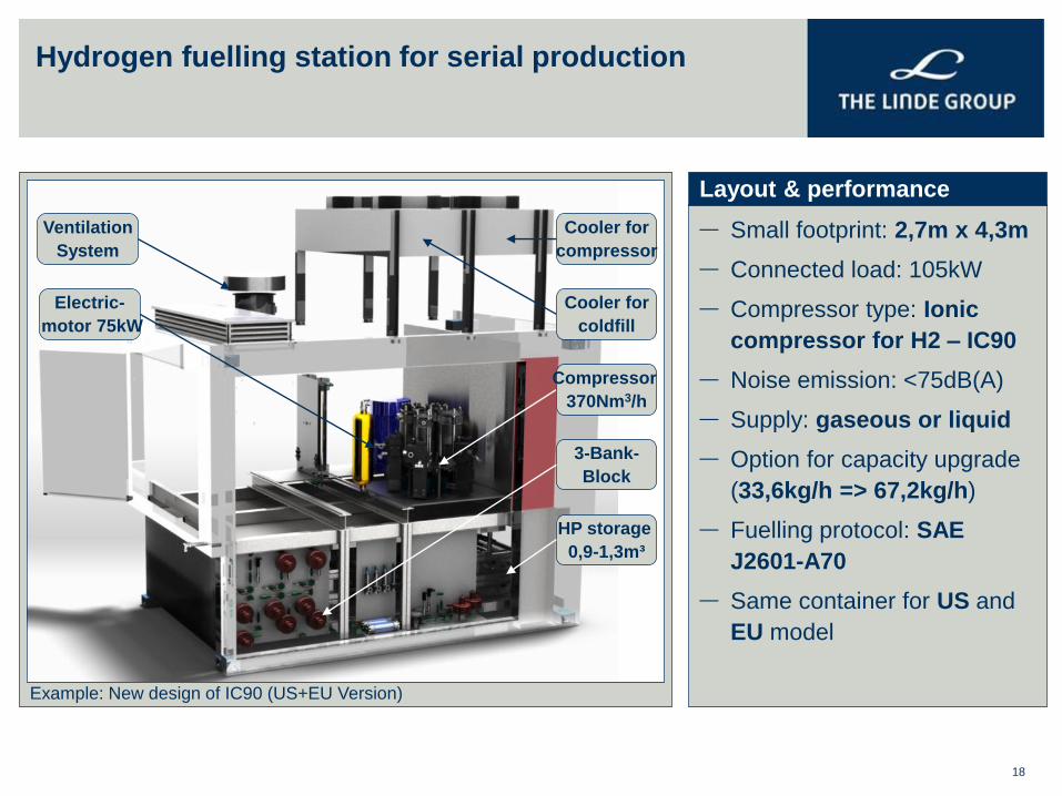
Hydrogen fuelling station for serial production
Example: New design of IC90 (US+EU Version)
— Small footprint: 2,7m x 4,3m
— Connected load: 105kW
— Compressor type: Ionic
compressor for H2 – IC90
— Noise emission: <75dB(A)
— Supply: gaseous or liquid
— Option for capacity upgrade
(33,6kg/h => 67,2kg/h)
— Fuelling protocol: SAE
J2601-A70
— Same container for US and
EU model
Layout & performance
Ventilation
System
Cooler for
compressor
Electric-
motor 75kW
Compressor
370Nm3/h
Cooler for
coldfill
3-Bank-
Block
HP storage
0,9-1,3m³
19
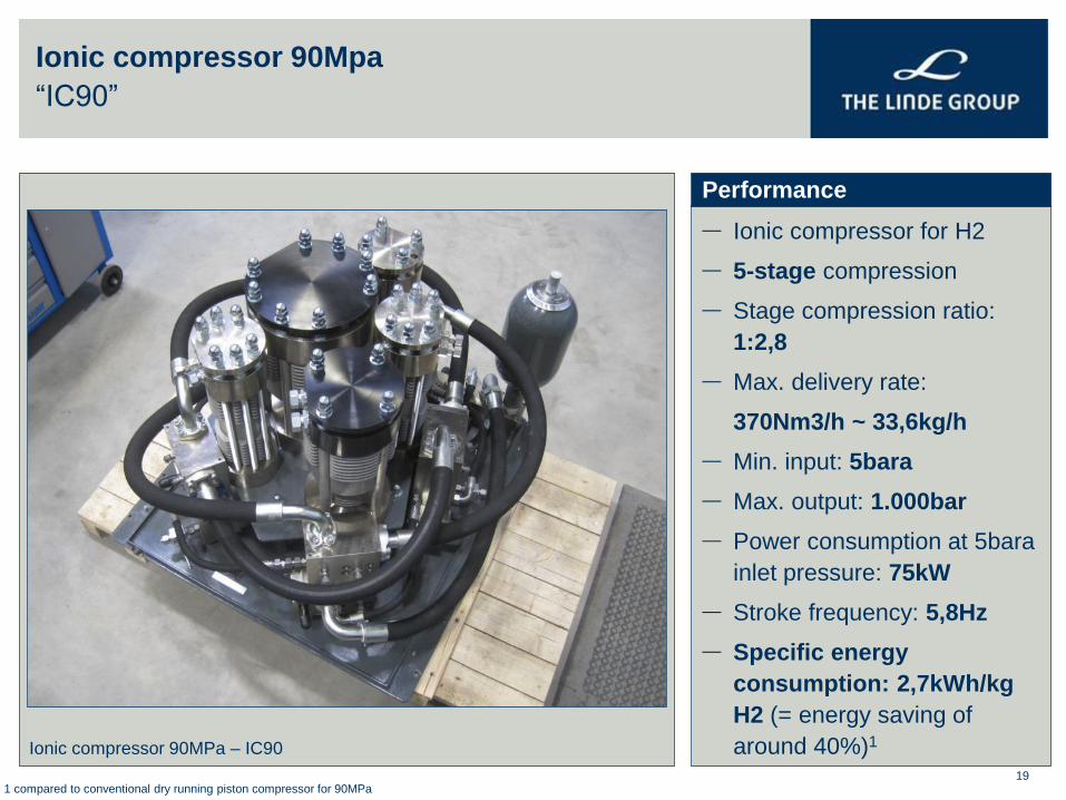
Ionic compressor 90Mpa
“IC90”
Ionic compressor 90MPa – IC90
— Ionic compressor for H2
— 5-stage compression
— Stage compression ratio:
1:2,8
— Max. delivery rate:
370Nm3/h ~ 33,6kg/h
— Min. input: 5bara
— Max. output: 1.000bar
— Power consumption at 5bara
inlet pressure: 75kW
— Stroke frequency: 5,8Hz
— Specific energy
consumption: 2,7kWh/kg
H2 (= energy saving of
around 40%)1
Performance
1 compared to conventional dry running piston compressor for 90MPa
20
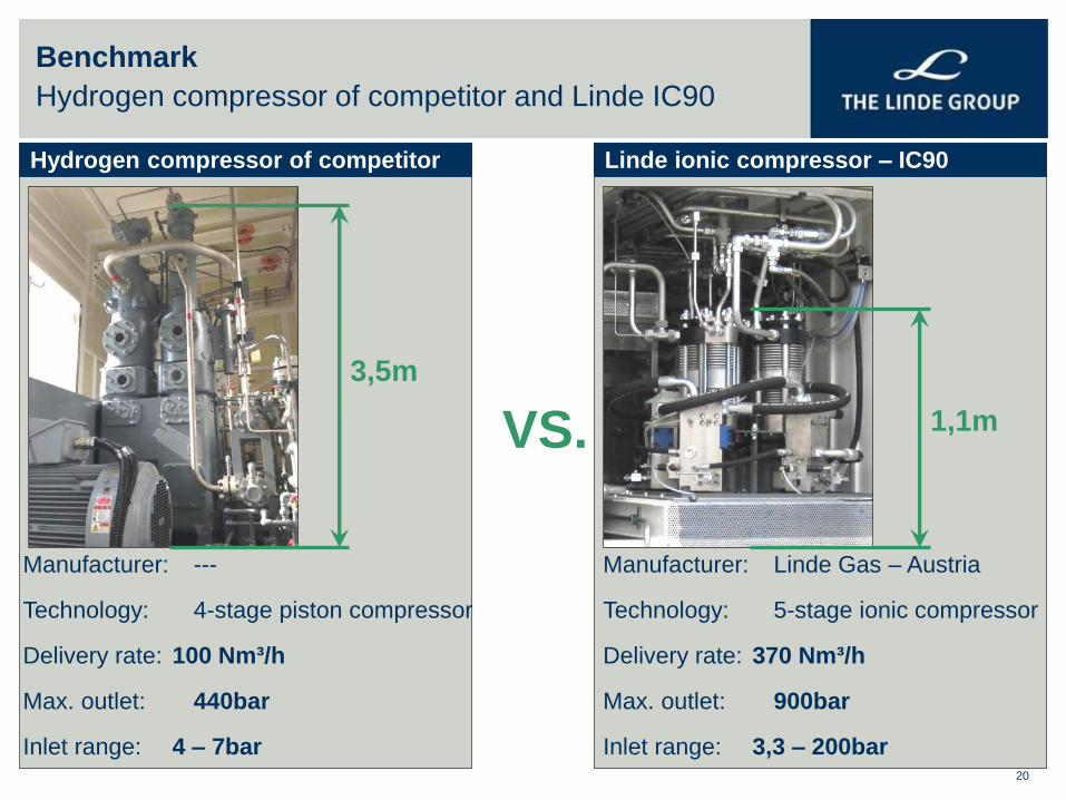
Benchmark
Hydrogen compressor of competitor and Linde IC90
Manufacturer: ---
Technology: 4-stage piston compressor
Delivery rate: 100 Nm³/h
Max. outlet: 440bar
Inlet range: 4 – 7bar
Manufacturer: Linde Gas – Austria
Technology: 5-stage ionic compressor
Delivery rate: 370 Nm³/h
Max. outlet: 900bar
Inlet range: 3,3 – 200bar
3,5m
1,1m
Hydrogen compressor of competitor Linde ionic compressor – IC90
VS.
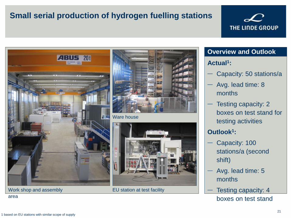
Small serial production of hydrogen fuelling stations
21
Work shop and assembly
area
Actual1:
— Capacity: 50 stations/a
— Avg. lead time: 8
months
— Testing capacity: 2
boxes on test stand for
testing activities
Outlook1:
— Capacity: 100
stations/a (second
shift)
— Avg. lead time: 5
months
— Testing capacity: 4
boxes on test stand
Overview and Outlook
Ware house
EU station at test facility
1 based on EU stations with similar scope of supply
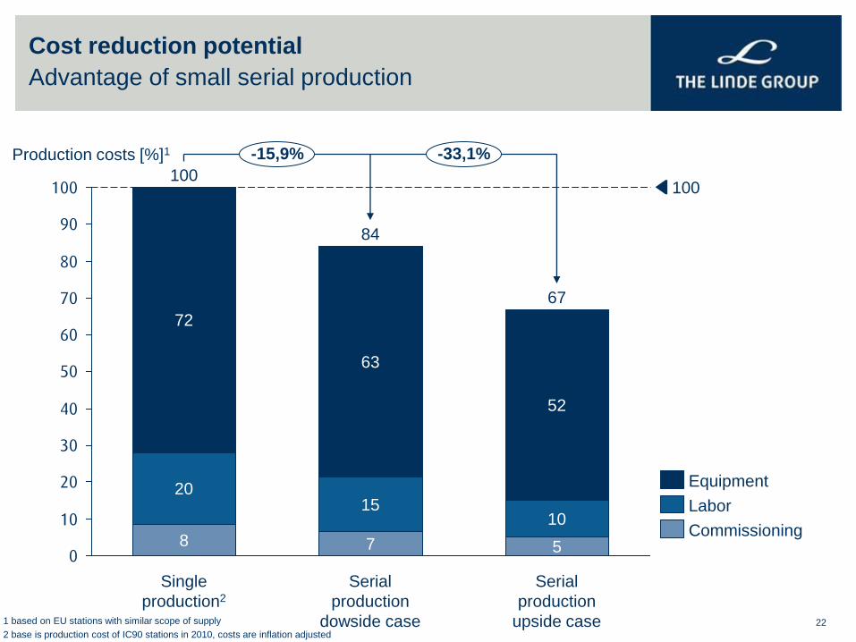
Cost reduction potential
Advantage of small serial production
22
0
10
20
30
40
50
60
70
80
90
100
10
5
Serial
production
upside case
8
72
20
67
-15,9% -33,1%
100
Production costs [%]1
52
7
84
Serial
production
dowside case
15
63
Single
production2
100
Commissioning
Labor
Equipment
1 based on EU stations with similar scope of supply
2 base is production cost of IC90 stations in 2010, costs are inflation adjusted
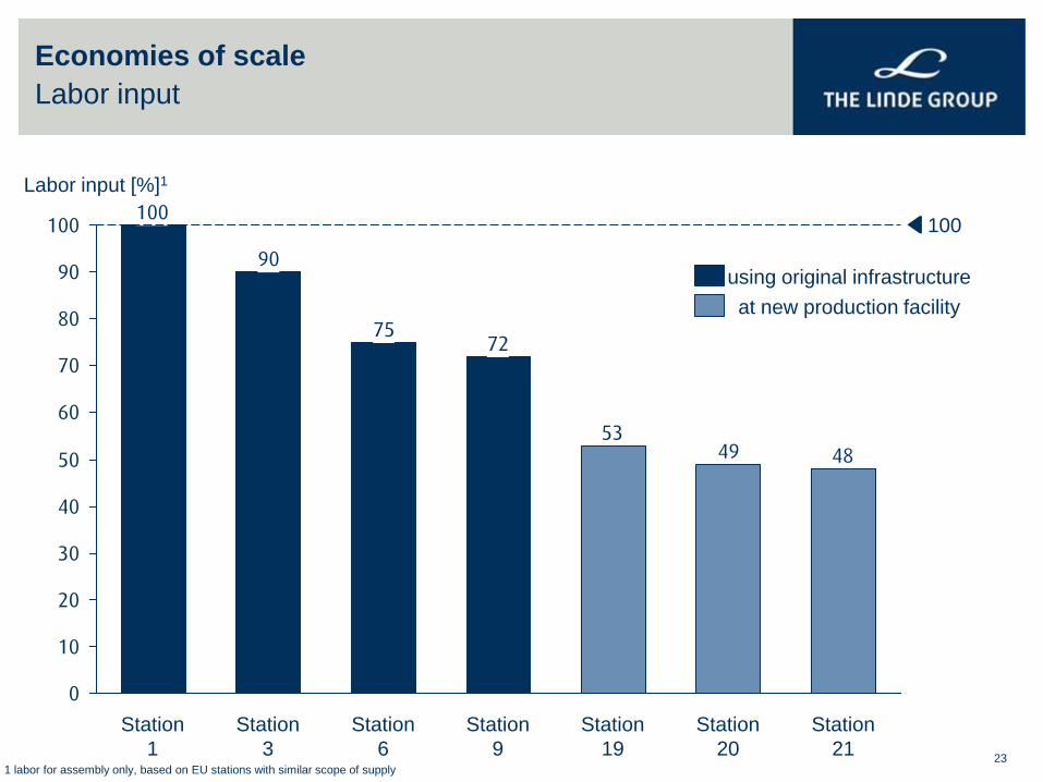
Economies of scale
Labor input
23
484953
7275
90
100
0
10
20
30
40
50
60
70
80
90
100
Station
21
Station
20
Station
19
Station
9
Station
6
Station
3
Station
1
Labor input [%]1
100
using original infrastructure
at new production facility
1 labor for assembly only, based on EU stations with similar scope of supply

24
Thank you