MANUFACTURING 3-D BRAIDED COMPOSITE TRUSSESautexrj.com/cms/zalaczone_pliki/4-07-3.pdf ·...
14
AUTEX Research Journal, Vol. 7, No3, September 2007 © AUTEX http://www.autexrj.org/No3-2007/0259.pdf 180 MANUFACTURING 3-D BRAIDED COMPOSITE TRUSSES Walaa El-Qaleoby 1 , Amira Gad El-Aela 1 Hemdan A. Abou-Taleb 1 and Aly H. El-Shiekh 2 1 Textile Engineering Department, Faculty of Engineering, Mansoura University, Mansoura 35516, Egypt. 2 College of Textiles, NC State University, Raleigh, NC 27965, USA. E-mail: [email protected] Fax: 0205 0224 4690 Abstract: A design methodology for the production of complex shapes through near net shape manufacturing is presented. The data was obtained by using a 3-D circular braiding machine that was designed and constructed by Prof. Dr. Aly El-Shiekh. Production of a braided truss shows the procedures required for producing right-angled and contoured parts, as well as the feasibility of producing such parts. The FRPC (Fibre-Reinforced Polymer Composites) truss reinforcement system was designed to simulate the conventional iron truss reinforcement system typically used in a concrete bridge deck. A technical comparison of FRPC (Fibre-Reinforced Polymer Composites) truss and steel truss is carried out with respect to weight, cost, compression and bending strength. Experimental results are presented to show how the nominal stresses (compression and bending) of 3-D braided composite trusses depend on truss height, truss width and truss angle, i.e. the number of working layers, number of yarns per each layer, braiding pattern and number of beats per cycle. It is shown that accurate mathematical models could be developed from the laboratory data to predict the compression and bending stresses of the truss from the basic braiding machine settings by using factorial design. The excellent fit of the predicted values with the measured values confirms that the mathematical models developed can be used to make accurate prediction of the compression and bending stresses from a knowledge of the truss specifications. Key words: 3D braided, composite trusses, FRPC 1. Introduction In the last 200 years, rapid advances in construction material technology have enabled civil engineers to achieve impressive gains in the safety, economy, and functionality of structures built to serve the common needs of society. The earliest FRPC (Fibre-Reinforced Polymer Composites) materials used glass fibres embedded in polymeric resins that were made available by the burgeoning petrochemical industry following World War II. The combination of high-strength, high-stiffness structural fibres with low-cost, light-weight, environmentally resistant polymers resulted in composite materials with mechanical properties and durability which were better than either of the constituents alone. Fibre materials with higher strength, higher stiffness, and lower density, such as boron, carbon, and aramid, were commercialised to meet the higher performance challenges of space exploration and air travel in the 1960s and 1970s. In the field of highway structures, several new FRPC (Fibre-Reinforced Polymer Composites) structural systems have been proposed, designed, and experimentally implemented. However, bridge decks have received the greatest amount of attention in recent years, due to their inherent advantages in strength and stiffness per unit weight as compared to traditional steel reinforced concrete (RC) decks. Reducing the weight of replacement decks in rehabilitation projects presents the opportunity for rapid replacement and reduction under dead load, thus raising the live load rating of the structure [1,2]. A bridge deck in this discussion is defined as a structural element that transfers loads transversely to supports, such as longitudinal running girders, cross beams, and/or stringers that bear on abutments. The connection of the deck to these underlying supports is typically made through applying shear
Transcript of MANUFACTURING 3-D BRAIDED COMPOSITE TRUSSESautexrj.com/cms/zalaczone_pliki/4-07-3.pdf ·...
AUTEX Research Journal, Vol. 7, No3, September 2007 © AUTEX
http://www.autexrj.org/No3-2007/0259.pdf 180
MANUFACTURING 3-D BRAIDED COMPOSITE TRUSSES
Walaa El-Qaleoby 1, Amira Gad El-Aela1 Hemdan A. Abou-Taleb1 and Aly H. El-Shiekh2
1Textile Engineering Department, Faculty of Engineering, Mansoura University, Mansoura 35516, Egypt. 2College of Textiles, NC State University, Raleigh, NC 27965, USA. E-mail: [email protected] Fax: 0205 0224 4690 Abstract:
A design methodology for the production of complex shapes through near net shape manufacturing is presented. The data was obtained by using a 3-D circular braiding machine that was designed and constructed by Prof. Dr. Aly El-Shiekh. Production of a braided truss shows the procedures required for producing right-angled and contoured parts, as well as the feasibility of producing such parts. The FRPC (Fibre-Reinforced Polymer Composites) truss reinforcement system was designed to simulate the conventional iron truss reinforcement system typically used in a concrete bridge deck. A technical comparison of FRPC (Fibre-Reinforced Polymer Composites) truss and steel truss is carried out with respect to weight, cost, compression and bending strength. Experimental results are presented to show how the nominal stresses (compression and bending) of 3-D braided composite trusses depend on truss height, truss width and truss angle, i.e. the number of working layers, number of yarns per each layer, braiding pattern and number of beats per cycle. It is shown that accurate mathematical models could be developed from the laboratory data to predict the compression and bending stresses of the truss from the basic braiding machine settings by using factorial design. The excellent fit of the predicted values with the measured values confirms that the mathematical models developed can be used to make accurate prediction of the compression and bending stresses from a knowledge of the truss specifications.
Key words:
3D braided, composite trusses, FRPC 1. Introduction In the last 200 years, rapid advances in construction material technology have enabled civil engineers to achieve impressive gains in the safety, economy, and functionality of structures built to serve the common needs of society. The earliest FRPC (Fibre-Reinforced Polymer Composites) materials used glass fibres embedded in polymeric resins that were made available by the burgeoning petrochemical industry following World War II. The combination of high-strength, high-stiffness structural fibres with low-cost, light-weight, environmentally resistant polymers resulted in composite materials with mechanical properties and durability which were better than either of the constituents alone. Fibre materials with higher strength, higher stiffness, and lower density, such as boron, carbon, and aramid, were commercialised to meet the higher performance challenges of space exploration and air travel in the 1960s and 1970s. In the field of highway structures, several new FRPC (Fibre-Reinforced Polymer Composites) structural systems have been proposed, designed, and experimentally implemented. However, bridge decks have received the greatest amount of attention in recent years, due to their inherent advantages in strength and stiffness per unit weight as compared to traditional steel reinforced concrete (RC) decks. Reducing the weight of replacement decks in rehabilitation projects presents the opportunity for rapid replacement and reduction under dead load, thus raising the live load rating of the structure [1,2]. A bridge deck in this discussion is defined as a structural element that transfers loads transversely to supports, such as longitudinal running girders, cross beams, and/or stringers that bear on abutments. The connection of the deck to these underlying supports is typically made through applying shear
AUTEX Research Journal, Vol. 7, No3, September 2007 © AUTEX
http://www.autexrj.org/No3-2007/0259.pdf 181
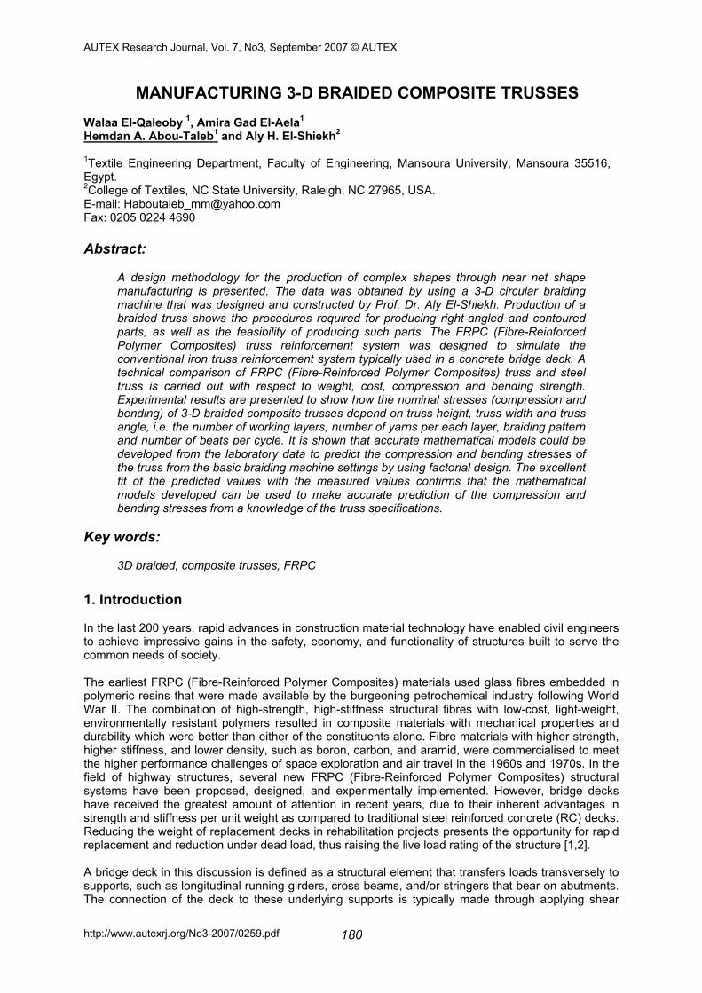
studs or a bolted connection in a simply supported condition that does not necessarily provide for composite action. The FRP decks which are commercially available at the present time can be classified according to two types of construction: sandwich and adhesively-bonded pultruded shapes [4]. (a) Sandwich Construction Sandwich structures have been widely used for applications in the aerospace, marine, and automotive industries, where stiffness and strength requirements must be met by structures with minimum weight, as explained in a number of textbooks on the subject [3]. Sandwich construction implies the use of strong, stiff face sheets that carry flexural loads and a low-density, bonded core material that separates the face sheets and ensures the composite action of the deck. Cellular materials are the most efficient core materials for weight-sensitive applications. Due to the ease with which face sheets can be changed in manufacturing, sandwich construction presents tremendous flexibility in design for varied depths and deflection requirements. The face sheets of sandwich bridge decks are primarily composed of E-glass mats and/or rovings infused with a polyester or vinylester resin. Current core materials are rigid foams or thin-walled cellular FRP materials, such as those shown in Figure 1 In such processes, the core and face sheets can be impregnated with resin and cured simultaneously. Changes in details related to materials, orientations, and the thickness of the FRP face sheets or core can be determined analytically and are easily accommodated in many of these processes [4].
Figure 1. Example of two types of sandwich construction (a) generic foam core; (b) proprietary (KSCI) corrugated cor (taken from Davalos et al. (2001) [Ref. 4])
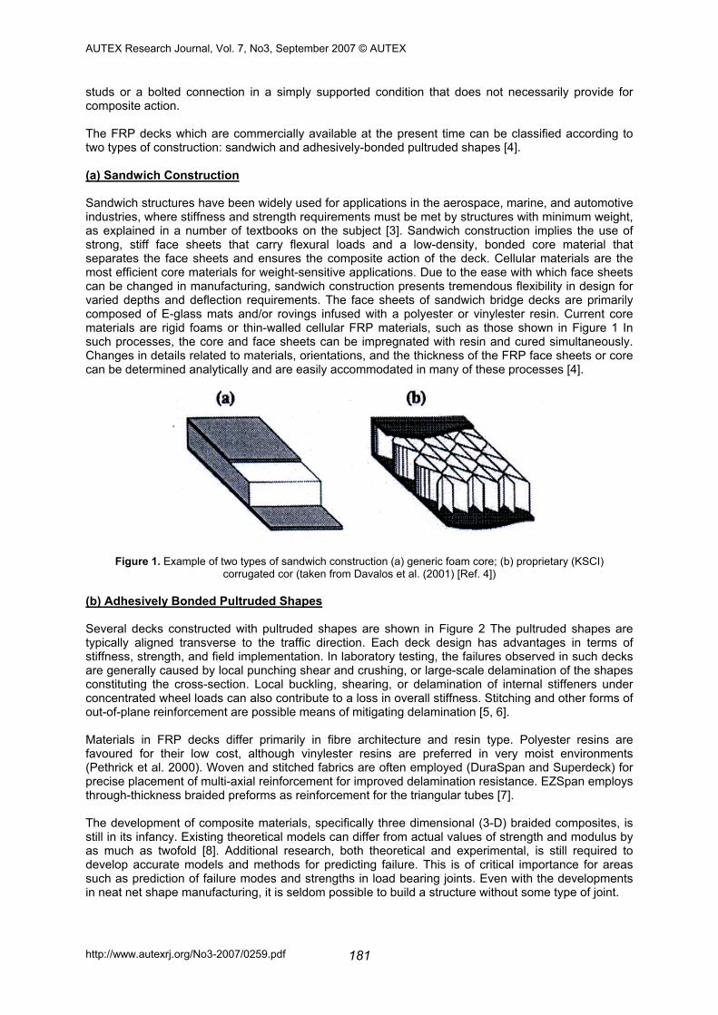
(b) Adhesively Bonded Pultruded Shapes Several decks constructed with pultruded shapes are shown in Figure 2 The pultruded shapes are typically aligned transverse to the traffic direction. Each deck design has advantages in terms of stiffness, strength, and field implementation. In laboratory testing, the failures observed in such decks are generally caused by local punching shear and crushing, or large-scale delamination of the shapes constituting the cross-section. Local buckling, shearing, or delamination of internal stiffeners under concentrated wheel loads can also contribute to a loss in overall stiffness. Stitching and other forms of out-of-plane reinforcement are possible means of mitigating delamination [5, 6]. Materials in FRP decks differ primarily in fibre architecture and resin type. Polyester resins are favoured for their low cost, although vinylester resins are preferred in very moist environments (Pethrick et al. 2000). Woven and stitched fabrics are often employed (DuraSpan and Superdeck) for precise placement of multi-axial reinforcement for improved delamination resistance. EZSpan employs through-thickness braided preforms as reinforcement for the triangular tubes [7]. The development of composite materials, specifically three dimensional (3-D) braided composites, is still in its infancy. Existing theoretical models can differ from actual values of strength and modulus by as much as twofold [8]. Additional research, both theoretical and experimental, is still required to develop accurate models and methods for predicting failure. This is of critical importance for areas such as prediction of failure modes and strengths in load bearing joints. Even with the developments in neat net shape manufacturing, it is seldom possible to build a structure without some type of joint.
AUTEX Research Journal, Vol. 7, No3, September 2007 © AUTEX
http://www.autexrj.org/No3-2007/0259.pdf 182
Figure 2. FRP decks produced from adhesively bonded pultruded shapes: (a) EZSpans (Atlantics Research); (b) Superdeck (Creative Pultrusions);
(c) DuraSpan (Martin Marietta Materials); (d) Square tube and plate deck (Strongwell) [Ref. 4]
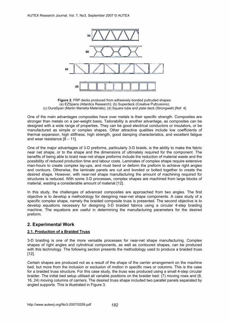
One of the main advantages composites have over metals is their specific strength. Composites are stronger than metals on a per-weight basis. Tailorability is another advantage, as composites can be designed with a wide range of properties. They can be good electrical conductors or insulators, or be manufactured as simple or complex shapes. Other attractive qualities include low coefficients of thermal expansion, high stiffness, high strength, good damping characteristics, and excellent fatigue and wear resistance [8 – 11]. One of the major advantages of 3-D preforms, particularly 3-D braids, is the ability to make the fabric near net shape, or to the shape and the dimensions of ultimately required for the component. The benefits of being able to braid near-net shape preforms include the reduction of material waste and the possibility of reduced production time and labour costs. Laminates of complex shape require extensive man-hours to create complex lay-ups, and must bend or deform the preform to achieve right angles and contours. Otherwise, the laminate panels are cut and bonded or bolted together to create the desired shape. However, with near-net shape manufacturing the amount of machining required for structures is reduced. With some 3-D processes, complex shapes are machined from large blocks of material, wasting a considerable amount of material [12]. In this study, the challenges of advanced composites are approached from two angles. The first objective is to develop a methodology for designing near-net shape components. A case study of a specific complex shape, namely the braided composite truss is presented. The second objective is to develop equations necessary for designing 3-D braided fabrics using a circular 4-step braiding machine. The equations are useful in determining the manufacturing parameters for the desired preform. 2. Experimental Work 2.1. Production of a Braided Truss 3-D braiding is one of the more versatile processes for near-net shape manufacturing. Complex shapes of right angles and cylindrical components, as well as contoured shapes, can be produced with this technology. The following section presents the methodology used to produce a braided truss [12]. Certain shapes are produced not as a result of the shape of the carrier arrangement on the machine bed, but more from the inclusion or exclusion of motion in specific rows or columns. This is the case for a braided truss structure. For this case study, the truss was produced using a small 4-step circular braider. The initial bed setup utilised all variable positions on the braider bed: (7) moving rows and (8, 16, 24) moving columns of carriers. The desired truss shape included two parallel panels separated by angled supports. This is illustrated in Figure 3.
AUTEX Research Journal, Vol. 7, No3, September 2007 © AUTEX
http://www.autexrj.org/No3-2007/0259.pdf 183
Figure 3. Sketch of braided truss
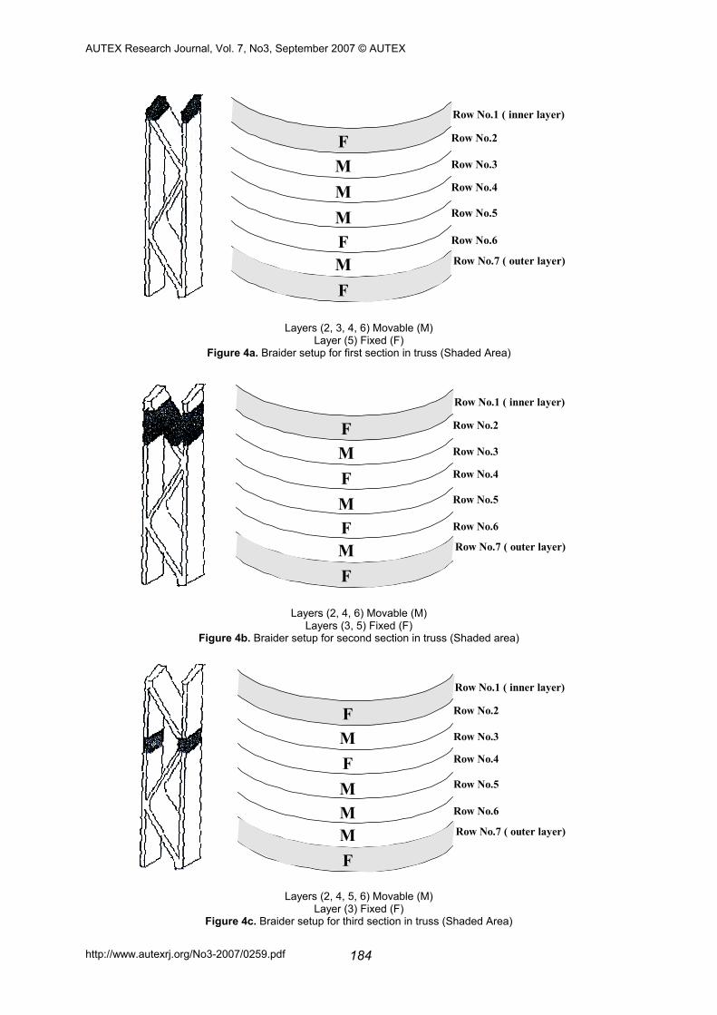
Using the (7×8, 7×16, 7×24) braider beds, four configurations were required to braid the truss. Each configuration was used to braid a different section along the truss lengthwise. These sections included:
- braiding the top, bottom and angled support panels, with the support connected to the top panel, for four cycles (Figure 4a),
- braiding the top, bottom and angled support panels as separate section (Figure 4b), - braiding the angled support panels for an additional length for four cycles (Figure 4c), and - braiding the top, bottom and angled support panels, with the support connected to the
bottom panel (Figure 4d). Although described as a connected area, the sections where the supports were ‘joined’ to a panel in fact constituted one integrated structure. Figures 4a-d illustrate the braider bed setup, machine motion and sections of the preform being braided. Note that the separation and connection of the different sections was achieved by blocking motion in one or more rows of carriers. For the support, extra length was required to separate the parallel panels while keeping them straight. This length determines the angle of the support and the distance separating the parallel panels. As the process requires separating and joining the braids several times, one repeat of the truss structure requires a great number of steps. Consolidation of the truss was a tedious process. The initial step was cutting gypsum wedges to fit the openings in the truss. The wedges were necessary to help the preform retain its shape during consolidation. After fitting and removing the wedges, the truss was placed in a rectangular mould and the mould was filled with resin. The mould assembly was placed in a room-temperature vacuum oven and evacuated to 1 torr (1mm Hg or 133.28 N / m2). This step removed air from the preform and resin while impregnating the fabric. The mould was removed from the oven and the wedges were inserted into their designated areas. The assembly was left to cure at room temperature for 24 hours, after which the wedges were removed. There were some concerns with the consolidation process. The first variations in wedge dimensions created resin-rich areas in some sections of the truss. The variation also hindered insertion of the wedges into the preform. Care must be taken to make wedges uniform and to ensure the production of a fabric with uniform spacing. Secondly, the act of inserting the wedges displaced the preform in some areas, as well as displacing large amounts of excess resin. The initial intention was to keep the areas open to aid the infiltration process. However; in hindsight, preserving the shape of the preform by inserting the wedges in the dry preform should have been the first priority. In addition, this would have reduced the level of waste and degree of messiness. Ideal consolidation methods for complex shapes would be the use of closed mould processes, such as resin transfer moulding.
Truss Angle
Width
Height
Constant Span Length = 40cm
AUTEX Research Journal, Vol. 7, No3, September 2007 © AUTEX
http://www.autexrj.org/No3-2007/0259.pdf 184
FM M M F M F
Row No.1 ( inner layer)
Row No.7 ( outer layer)
Row No.2
Row No.3
Row No.4
Row No.5
Row No.6
Layers (2, 3, 4, 6) Movable (M) Layer (5) Fixed (F)
Figure 4a. Braider setup for first section in truss (Shaded Area)
FM F M F M F
Row No.1 ( inner layer)
Row No.7 ( outer layer)
Row No.2
Row No.3
Row No.4
Row No.5
Row No.6
Layers (2, 4, 6) Movable (M) Layers (3, 5) Fixed (F)
Figure 4b. Braider setup for second section in truss (Shaded area)
FM F M M M F
Row No.1 ( inner layer)
Row No.7 ( outer layer)
Row No.2
Row No.3
Row No.4
Row No.5
Row No.6
Layers (2, 4, 5, 6) Movable (M) Layer (3) Fixed (F)
Figure 4c. Braider setup for third section in truss (Shaded Area)
AUTEX Research Journal, Vol. 7, No3, September 2007 © AUTEX
http://www.autexrj.org/No3-2007/0259.pdf 185
FM F M F M F
Row No.1 ( inner layer)
Row No.7 ( outer layer)
Row No.2
Row No.3
Row No.4
Row No.5
Row No.6
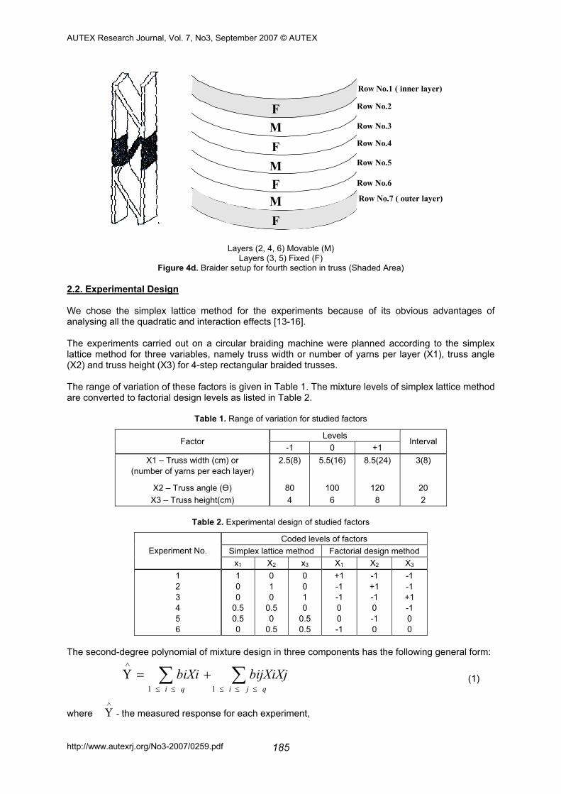
Layers (2, 4, 6) Movable (M) Layers (3, 5) Fixed (F)
Figure 4d. Braider setup for fourth section in truss (Shaded Area) 2.2. Experimental Design We chose the simplex lattice method for the experiments because of its obvious advantages of analysing all the quadratic and interaction effects [13-16]. The experiments carried out on a circular braiding machine were planned according to the simplex lattice method for three variables, namely truss width or number of yarns per layer (X1), truss angle (X2) and truss height (X3) for 4-step rectangular braided trusses. The range of variation of these factors is given in Table 1. The mixture levels of simplex lattice method are converted to factorial design levels as listed in Table 2.
Table 1. Range of variation for studied factors
Levels Factor
-1 0 +1 Interval
X1 – Truss width (cm) or (number of yarns per each layer)
X2 – Truss angle (Ө ) X3 – Truss height(cm)
2.5(8)
80 4
5.5(16)
100 6
8.5(24)
120 8
3(8)
20 2
Table 2. Experimental design of studied factors
Coded levels of factors Simplex lattice method Factorial design method Experiment No.
x1 X2 x3 X1 X2 X3 1 2 3 4 5 6
1 0 0
0.5 0.5 0
0 1 0
0.5 0
0.5
0 0 1 0
0.5 0.5
+1 -1 -1 0 0 -1
-1 +1 -1 0 -1 0
-1 -1 +1 -1 0 0
The second-degree polynomial of mixture design in three components has the following general form:
∑∑≤≤≤≤≤
∧
+=Υqjiqi
bijXiXjbiXi11
(1)
where ∧
Υ - the measured response for each experiment,
AUTEX Research Journal, Vol. 7, No3, September 2007 © AUTEX
http://www.autexrj.org/No3-2007/0259.pdf 186
bi - the coefficients of the main factor effects, bij - the coefficients of the interaction effects, and q - the number of the chosen factors. In order to determine the regression coefficients, the response Y has to be found by using different experimental combinations of the variables under consideration. The mathematical models obtained by the simplex lattice method could be modified by converting the coded levels of factors (0, 0.5, 1) to correspond with the factorial design levels (-1, 0, +1), as listed in Table II. 2.3. Materials and Test Methods 6.6×2 Ktex nylon yarns were chosen, in order to be as consistent with the assumptions in reference [17] as possible.
1
2
3
4
5
6
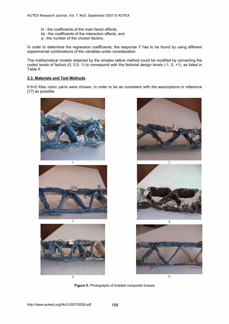
Figure 5. Photographs of braided composite trusses
AUTEX Research Journal, Vol. 7, No3, September 2007 © AUTEX
http://www.autexrj.org/No3-2007/0259.pdf 187
Six braided composite trusses were produced at different operating conditions as shown in Table 1 and Figure 5. The quantities measured experimentally are bending and compression stresses. The compression and bending stresses were measured using VEB Werkstoff-Prufmaschinen Leipzig and ELE International Testers respectively, as shown in Figures 6 and 7.
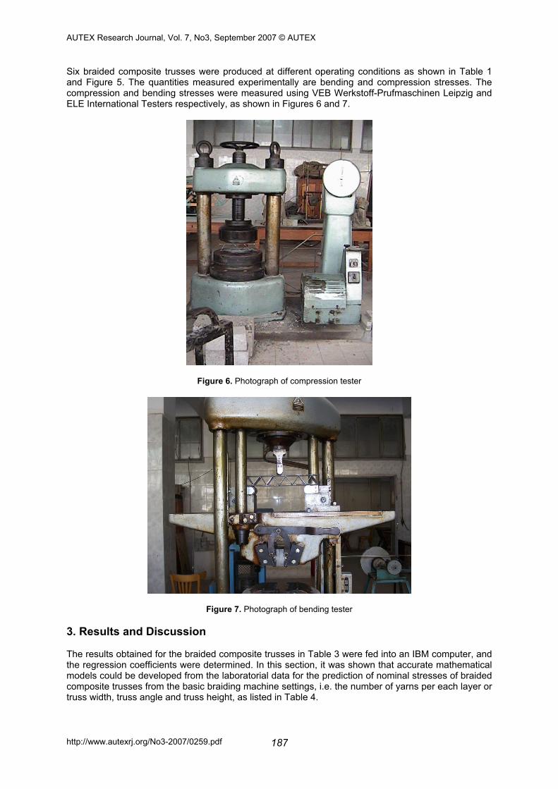
Figure 6. Photograph of compression tester
Figure 7. Photograph of bending tester
3. Results and Discussion The results obtained for the braided composite trusses in Table 3 were fed into an IBM computer, and the regression coefficients were determined. In this section, it was shown that accurate mathematical models could be developed from the laboratorial data for the prediction of nominal stresses of braided composite trusses from the basic braiding machine settings, i.e. the number of yarns per each layer or truss width, truss angle and truss height, as listed in Table 4.
AUTEX Research Journal, Vol. 7, No3, September 2007 © AUTEX
http://www.autexrj.org/No3-2007/0259.pdf 188
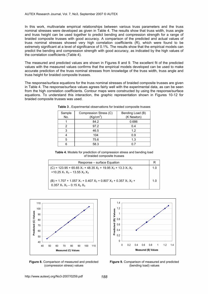
In this work, multivariate empirical relationships between various truss parameters and the truss nominal stresses were developed as given in Table 4. The results show that truss width, truss angle and truss height can be used together to predict bending and compression strength for a range of braided composite trusses with good accuracy. A comparison of the predicted and actual values of truss nominal stresses showed very high correlation coefficients (R), which were found to be extremely significant at a level of significance of 0.1%. The results show that the empirical models can predict the bending and compression strength with good accuracy, as indicated by the high values of the correlation coefficients (Table 4). The measured and predicted values are shown in Figures 8 and 9. The excellent fit of the predicted values with the measured values confirms that the empirical models developed can be used to make accurate prediction of the truss nominal stresses from knowledge of the truss width, truss angle and truss height for braided composite trusses. The response/surface equations for the truss nominal stresses of braided composite trusses are given in Table 4. The response/surface values agrees fairly well with the experimental data, as can be seen from the high correlation coefficients. Contour maps were constructed by using the response/surface equations. To understand this interaction, the graphic representation shown in Figures 10-12 for braided composite trusses was used.
Table 3 . Experimental observations for braided composite trusses
Sample No.
Compression Stress (C) (Kg/cm2)
Bending Load (B) (K Newton)
1 84.2 0.686 2 97.2 0.4 3 46.5 1.2 4 104 0.9 5 75.6 1.3 6 58.3 0.7
Table 4. Models for prediction of compression stress and bending load
of braided composite trusses
Response – surface Equation R
(C) = 123.95 + 65.65 X1 + 48.35 X2 + 19.95 X3 + 13.3 X1 X2 +10.25 X1 X3 – 13.55 X2 X3 (B) = 1.707 + 1.057 X1 + 0.407 X2 + 0.807 X3 + 0.357 X1 X2 + 0.357 X1 X3 – 0.15 X2 X3
1.0
1.0
40
50
60
70
80
90
100
110
40 50 60 70 80 90 100 110
Measured (C) Values
Pre
dict
ed (C
) Val
ues
0
0.2
0.4
0.6
0.8
1
1.2
1.4
0 0.2 0.4 0.6 0.8 1 1.2 1.4
Measured (B) Values
Pre
dic
ted
(B
) V
alu
es
Figure 8. Comparison of measured and predicted (compression stress) values
Figure 9. Comparison of measured and predicted (bending load) values
AUTEX Research Journal, Vol. 7, No3, September 2007 © AUTEX
http://www.autexrj.org/No3-2007/0259.pdf 189
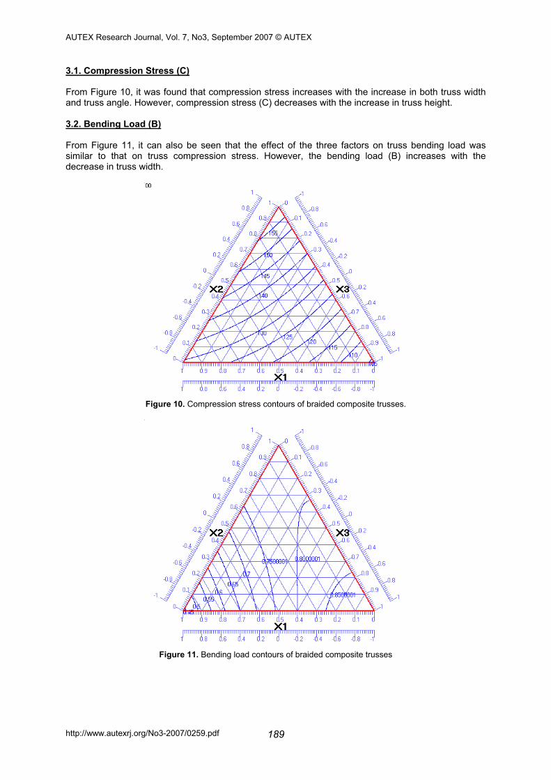
3.1. Compression Stress (C) From Figure 10, it was found that compression stress increases with the increase in both truss width and truss angle. However, compression stress (C) decreases with the increase in truss height. 3.2. Bending Load (B) From Figure 11, it can also be seen that the effect of the three factors on truss bending load was similar to that on truss compression stress. However, the bending load (B) increases with the decrease in truss width.
Figure 10. Compression stress contours of braided composite trusses.
Figure 11. Bending load contours of braided composite trusses
AUTEX Research Journal, Vol. 7, No3, September 2007 © AUTEX
http://www.autexrj.org/No3-2007/0259.pdf 190
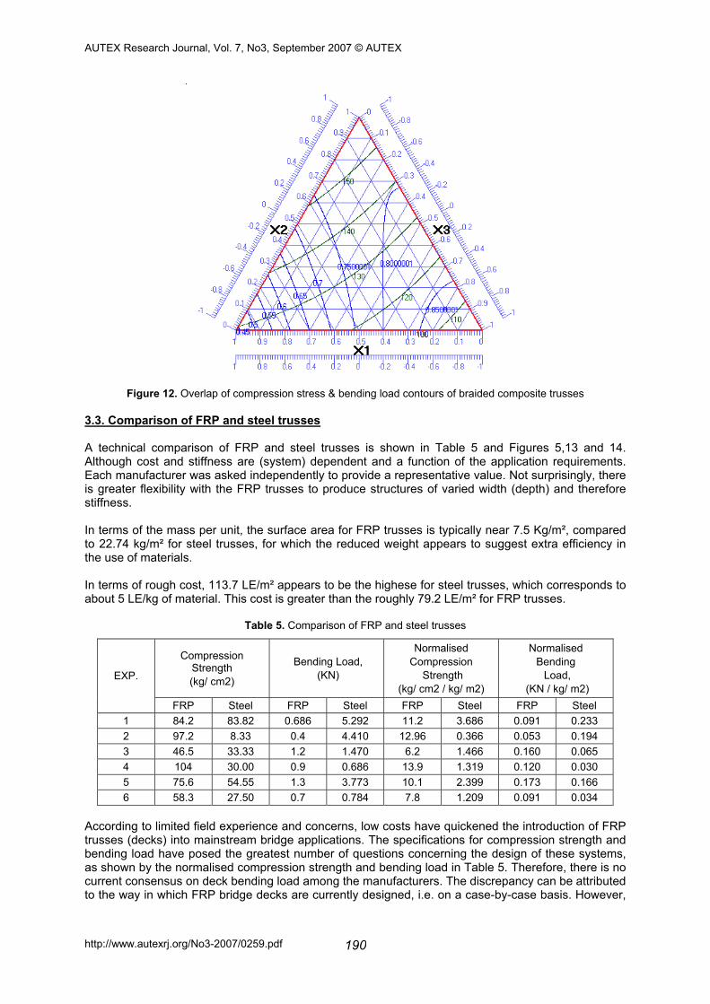
Figure 12. Overlap of compression stress & bending load contours of braided composite trusses 3.3. Comparison of FRP and steel trusses
A technical comparison of FRP and steel trusses is shown in Table 5 and Figures 5,13 and 14. Although cost and stiffness are (system) dependent and a function of the application requirements. Each manufacturer was asked independently to provide a representative value. Not surprisingly, there is greater flexibility with the FRP trusses to produce structures of varied width (depth) and therefore stiffness.
In terms of the mass per unit, the surface area for FRP trusses is typically near 7.5 Kg/m², compared to 22.74 kg/m² for steel trusses, for which the reduced weight appears to suggest extra efficiency in the use of materials.
In terms of rough cost, 113.7 LE/m² appears to be the highese for steel trusses, which corresponds to about 5 LE/kg of material. This cost is greater than the roughly 79.2 LE/m² for FRP trusses.
Table 5. Comparison of FRP and steel trusses
Compression Strength (kg/ cm2)
Bending Load, (KN)
Normalised Compression
Strength (kg/ cm2 / kg/ m2)
Normalised Bending Load,
(KN / kg/ m2)
EXP.
FRP Steel FRP Steel FRP Steel FRP Steel 1 84.2 83.82 0.686 5.292 11.2 3.686 0.091 0.233 2 97.2 8.33 0.4 4.410 12.96 0.366 0.053 0.194 3 46.5 33.33 1.2 1.470 6.2 1.466 0.160 0.065 4 104 30.00 0.9 0.686 13.9 1.319 0.120 0.030 5 75.6 54.55 1.3 3.773 10.1 2.399 0.173 0.166 6 58.3 27.50 0.7 0.784 7.8 1.209 0.091 0.034
According to limited field experience and concerns, low costs have quickened the introduction of FRP trusses (decks) into mainstream bridge applications. The specifications for compression strength and bending load have posed the greatest number of questions concerning the design of these systems, as shown by the normalised compression strength and bending load in Table 5. Therefore, there is no current consensus on deck bending load among the manufacturers. The discrepancy can be attributed to the way in which FRP bridge decks are currently designed, i.e. on a case-by-case basis. However,
AUTEX Research Journal, Vol. 7, No3, September 2007 © AUTEX
http://www.autexrj.org/No3-2007/0259.pdf 191
uncertainty in defining bending load limits is also present in existing design guidelines for conventional structures.
The situation facing the FRP bridge deck industry is not dissimilar to that faced by previous industries, such as steel and concrete, upon the introduction of new materials onto a well-entrenched market. When iron was first introduced as a building material, it was fashioned into shapes that resembled timber; perhaps the FRP decks of tomorrow will develop to take fuller advantage of the material properties and manufacturing methods of FRP materials, as experience and comfort with them grow.
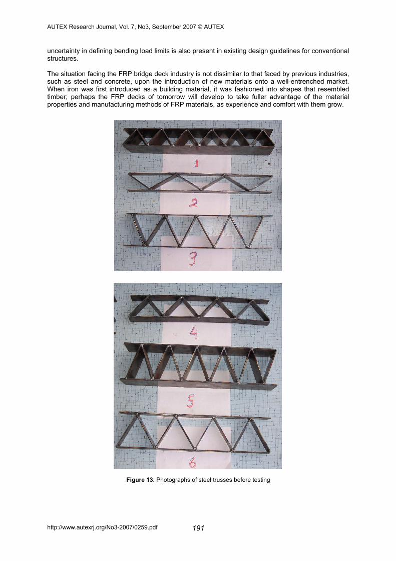
Figure 13. Photographs of steel trusses before testing
AUTEX Research Journal, Vol. 7, No3, September 2007 © AUTEX
http://www.autexrj.org/No3-2007/0259.pdf 192
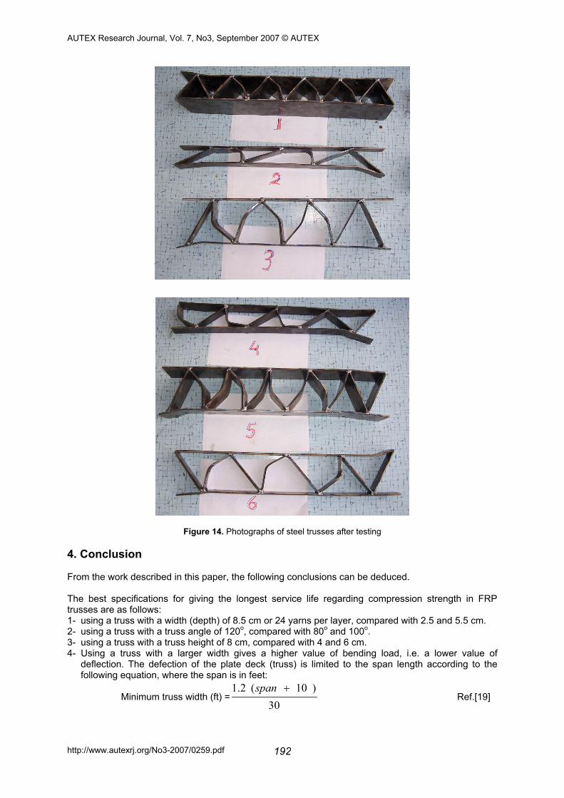
Figure 14. Photographs of steel trusses after testing 4. Conclusion From the work described in this paper, the following conclusions can be deduced. The best specifications for giving the longest service life regarding compression strength in FRP trusses are as follows: 1- using a truss with a width (depth) of 8.5 cm or 24 yarns per layer, compared with 2.5 and 5.5 cm. 2- using a truss with a truss angle of 120o, compared with 80o and 100o. 3- using a truss with a truss height of 8 cm, compared with 4 and 6 cm. 4- Using a truss with a larger width gives a higher value of bending load, i.e. a lower value of
deflection. The defection of the plate deck (truss) is limited to the span length according to the following equation, where the span is in feet:
Minimum truss width (ft) =30
)10(2.1 +span Ref.[19]
AUTEX Research Journal, Vol. 7, No3, September 2007 © AUTEX
http://www.autexrj.org/No3-2007/0259.pdf 193
5- using an FRP truss with a truss angle of 120o and a truss height of 8 cm gives the highest bending load (the lowest deflection).
From observation, it is seen that both the weight and cost of the FRP truss is much less than the steel truss. Also, both the normalised compression strength and bending load of the FRP truss are much greater than the steel truss. References:
1. Alampalli, S., O’Connor, J., Yannotti A. P., and Luu, K. T. (1999) ‘Fibre-reinforced plastics for bridge construction and rehabilitation in New York.’ Materials and Construction: Exploring the connection, Proc., 5th Materials Engineering Congress, L. C. Bank, ed., ASCE, Reston, Va., pp344-350.
2. Dagher, H. J. Schmidt, A. L., Abdel-Magid B., and Iyer, S. (1997) “FRP post-tensioning of laminated timber bridges”. Evolving Technologies for the Competitive Edge, Proc., 42nd Int. SAMPE Symposium, Vol. 2, Society for the advancement of material and process Engineering, Covina, Calif., pp933-938.
3. Vinson, J. R. (1999). The behavior of sandwich structures of isotropic and composite materials, Technomic, Lancaster, Pa.
4. Davalos, J. F., Qiao, P. Z., Xu, X. F., Robinson, J., and Barth, K. E. (2001). ‘Modeling and characterization of fibre-reinforced plastic honeycomb sandwich panels for highway bridge applications’, J. Compos. Constr., 52 (3-4), pp441-452.
5. GangaRao, H. V. S., Thippeswamy, H. K., Shekar, V., and Craigo, C. (1999). ‘Development of glass fibre reinforced polymer composite bridge deck.’ SAMPE J., 35 (4), 12 – 24.
6. Harik, I., et al. (1999). ‘Static testing on FRP bridge deck panels.’ Proc. 44th Int. SAMPE Symposium and Exhibition, Vol. 2, Society for the Advancement of Material and Process Engineering, Covina, Calif., 1643 – 1954.
7. Pethrick, R. A., Boinard, E., Dalzel-Job, J., and MacFarlane, C. J. (2000). ‘Influence of resin chemistry on water uptake and environmental aging in glass fibre reinforced composites: Polyester and vinyl ester laminates.’ J. Mater. Sci., 35(8), 1931 –1937.
8. Dostal, Cyril A., senior ed., Engineering Materials Handbook, Volume 1 : Composites, Metals Park, OH: ASM international.
9. Eckold, Geoff, Design and Manufacture of Composite Structure, NY, : McGraw-Hill, 1994. 10. Pilato, Louis A and Michael J. Michno. Advanced Composite Materials, New York, NY: Springer-
Verlag, 1994. 11. Epon® Resin Structural Manual, Shell Publication #SC:67-81 February 1992, PP. 9 – 13. 12. Reid Rona Levetta, ‘Structural Mechanics of Textile Composites: Effect of Braid Construction
and Geometric Parameters on Composite Performance.’ Ph.D. Dissertation, North Carolina State University, 1998.
13. Johnson N. L. and Leone F. C., ‘Statistics and Experimental Design in Engineering and the Physical Sciences’. John Wiley, NY, 1977.
14. Montgomery D. C., ‘Design and Analysis of Experiments’, John Wiley, NY, 1984. 15. Akhnazarova S. and Kafarov V., ‘Experimental Publishers, Optimization in Chemistry and
Chemical Engineering’, Mir, Moscow, 1978, (in Russian). 16. Abou-Taleb H.A., ‘Drapeability of Fabrics- Part II : A New Objective Method of Optimizing some
Tailoring Variables With Respect to Drapeability Using Mixture Design’, 4th International Engineering Conference, Mansoura–Sharm El-Sheikh, April 20-22, 2004, PP. (399-413)
17. Hammad, Mohamed A. ‘Mechanics of Modern Spinning Technology: 3-D Braiding.’ Ph.D. Dissertation. North Carolina State University and Alexandria University. November 1990.
18. Lopez–Anido, R. (2001). ‘Life-cycle cost survey of concrete decks – A benchmark for FRP bridge deck replacement’, (CD-Rom), Proc., 80th Transportation Research Board Meeting.
19. Bakis, C. E. et al., ‘Fibre-reinforced Polymer Composites for Construction: State of the Art Review’. Journal of Composites for Construction, May 2002, P. (73 – 87).


![MANUFACTURING 3-D BRAIDED COMPOSITE TRUSSES · 2010. 5. 25. · through-thickness braided preforms as reinforcement for the triangular tubes [7]. The development of composite materials,](https://static.fdocuments.net/doc/165x107/60d8496f3b243a3dec5dc269/manufacturing-3-d-braided-composite-2010-5-25-through-thickness-braided-preforms.jpg)