
Manuale DCC DVC - Benvenuto su Seatrevi.it INDEX INHALTSVERZEICHNIS INDEX INDICE 08.02...
47
DCC/DVC All rights reserved © WAMGROUP • SCREW BATCH FEEDERS • SCHNECKENDOSIERER • DOSEURS A VIS • DOSATORI A COCLEA CATALOGUE No. TO.1000 ISSUE A1 DATE OF LATEST UPDATE CREATION DATE CIRCULATION 100 08 / 2002 11.02
Transcript of Manuale DCC DVC - Benvenuto su Seatrevi.it INDEX INHALTSVERZEICHNIS INDEX INDICE 08.02...

DCC/DVC
All
right
s re
serv
ed ©
WA
MG
RO
UP
• SCREW BATCH FEEDERS
• SCHNECKENDOSIERER
• DOSEURS A VIS
• DOSATORI A COCLEA
CATALOGUE No. TO.1000
ISSUEA1
DATE OF LATEST UPDATE
CREATION DATE
CIRCULATION100
08 / 2002
11.02

INDEX
INDEX
INHALTSVERZEICHNIS
INDEX
INDICE
08.02
TO.1000
-
-
-
-
DCC•DVC
TECHNICAL CATALOGUE
INTRODUCTION............................................................................GENERAL VIEW...........................................................................GENERAL VIEW - ACCESSORIES................................................TECHNICAL DATA........................................................................TECHNICAL DATA AND PERFORMANCE.......................................APPROXIMATE THROUGHPUTS...................................................ORDER CODES............................................................................DIMENSIONS................................................................................
CATALOGUE TECNIQUE
INTRODUCTION............................................................................SCHÉMA GÉNÉRAL .....................................................................SCHÉMA GÉNÉRAL - ACCESSOIRES...........................................CARACTÉRISTIQUES TECHNIQUES............................................CARACTÉRISTIQUES TECHNIQUES E REPRÉSENTATION.............DEBITS INDICATIFS......................................................................CODES DE SELECTION................................................................ENCOMBREMENTS.......................................................................
TECHNISCHER KATALOG
EINFÜHRUNG..............................................................................ALLGEMEINES SCHEMA ...............................................................ALLGEMEINES SCHEMA - ZUBEHÖR.............................................TECHNISCHE DATEN......................................................................TECHNISCHE DATEN UND LEISTUNGSWERTE...............................DURCHSATZ CIRCAWERTE...........................................................BESTELLCODES............................................................................PLATZBEDARF..............................................................................
CATALOGO TECNICO
INTRODUZIONE..............................................................................SCHEMA GENERALE .....................................................................SCHEMA GENERALE - ACCESSORI...............................................DATI TECNICI .................................................................................DATI TECNICI E RAPPRESENTAZIONE............................................PORTATE INDICATIVE.....................................................................CODICI DI SCELTA..........................................................................INGOMBRI......................................................................................
1
MAINTENANCE CATALOGUE
OPERATION AND MAINTENANCE...................................................
WARTUNGSKATALOG
BETRIEBS- UND WARTUNGSANLEITUNG...................................
CATALOGUE D’ENTRETIEN
UTILISATION ET ENTRETIEN............................................................
CATALOGO DI MANUTENZIONE
USO E MANUTENZIONE..............................................................
2
M. .22<.39
SPARE PARTS CATALOGUE
SPARE PARTS................................................................................
ERSATZTEILKATALOG
ERSATZTEIL...............................................................................
CATALOGUE PIECES DE RECHANGE
PIECES DE RECHANGE................................................................
CATALOGO RICAMBI
RICAMBI........................................................................................
3
R. . 42<.47
T..04<.....06.07<.13.14.15.16.17.18.19
T..04<.....06.07<.13.14.15.16.17.18.19
M. .22<.39
R. . 42<.47

TE
CH
NIC
AL
CA
TAL
OG
UE
All
right
s re
serv
ed ©
WA
MG
RO
UP
1
• SCREW BATCH FEEDERSTECHNICAL CATALOGUE
• SCHNECKENDOSIERERTECHNISCHER KATALOGUE
• DOSEURS A VISCATALOGUE TECHNIQUE
• DOSATORI A COCLEACATALOGO TECNICO
CATALOGUE No. TO.1000.T
ISSUEA1
DATE OF LATEST UPDATE
CREATION DATE
CIRCULATION100
08 / 2002
DCC/DVC
11.02

DCC•DVC
08.02
1
TO.1000.T.
-
-
-
- 4
INTRODUCTION
EINFÜHRUNG
INTRODUCTION
INTRODUZIONE
CAREFULLY READ ALL THESAFETY INDICATIONS LISTEDIN THIS MANUAL AND NOTEALL THE WARNING SIGNSFIXED ON THE MACHINE.ENSURE THAT THESE ARE AL-WAYS WELL LEGIBLE ANDREPLACE THEM IF DAMAGEDOR LACKING.
Before starting to operate on themachine or parts of it, attentive-ly read the entire manual in or-der to have thorough knowledgeof the operating modes and thecontrol devices. Do not postponelearning until the time of opera-tion and do not allow unauthor-ised persons without the appro-priate knowledge to operate onthe machine.
DEFINITIONSExplained below are the defi-nitions used in this manual forthe warnings fixed on the prod-uct.
QUALIFIED PERSONNELQualified personnel are thosepersons who have specificknowledge of our machines, orwho however have specifictechnical qualifications in theelectrical or mechanical sec-tor.
DANGERSignals the possibility of anevent which may lead to death,serious injury or immense ma-terial damage if adequate pre-cautionary measures are nottaken.
WARNINGSignals the possibility of anevent which may lead to lightinjury to things or persons ifadequate precautionary meas-ures are not taken.The electrical equipment is to beused only in conformity with thetechnical purpose for which itwas constructed.Any tampering, the use of sup-plementary devices not sold orrecommended by the manufac-turer, and unauthorised exten-sions may cause damage to per-sons or things.
LEGGERE ATTENTAMENTE LEINDICAZIONI DI SICUREZZAELENCATE IN QUESTO MA-NUALE E ANNOTARE I SEGNA-LI FISSATI SULLA MACCHINA.QUESTI DEVONO ESSERESEMPRE BEN LEGGIBILI EDEVONO ESSERE SOSTITUITISE SONO DANNEGGIATI OMANCANO.
Prima di avviare la macchina ole parti di essa, leggere attenta-mente tutto il manuale in ordine,dopo aver approfondito la cono-scenza del modo di funziona-mento e il controllo dell’apparec-chio. Non rimandare tale prepa-razione e non permettere a per-sone non autorizzate e prive del-le appropriate conoscenze di farfunzionare la macchina.
DEFINIZIONIQui di seguito sono chiarite ledefinizioni usate in questomanuale per fissare il pericolodel prodotto.
PERSONALE QUALIFICATOSono quelle persone che han-no specifiche conoscenze del-la macchina, o che comunquepossiedono una preparazionetecnico specifica nel settoreelettro - meccanico.
PERICOLOSegnala la possibilità di unevento che può portare al de-cesso, gravi lesioni o dannimateriali ingenti se non siadottano adeguate misure.
AVVERTENZESegnala la possibilità del veri-ficarsi di un evento che puòportare a lievi lesioni a cose opersone se non si adottanoadeguate misure.L’apparecchiatura elettrica va uti-lizzata solo conformemente alloscopo tecnico per la quale è sta-ta costruita.Eventuali manomissioni, l’impie-go di dispositivi supplementarinon venduti o raccomandati dalcostruttore, ampliamenti non au-torizzati, possono essere causadi danni a persone o cose.
LIRE ATTENTIVEMENT LESCONSIGNES DE SÉCURITÉFOURNIES DANS CE MANUELET PRENDRE NOTE DES SI-GNAUX QUI SONT FIXÉS SURLA MACHINE.CES SIGNAUX DOIVENT TOU-JOURS ETRE BIEN LISIBLESET QUAND ILS SONT ABIMÉSOU MANQUANTS ILS DOIVENTETRE REMPLACÉS.
Avant de mettre la machine oules parties de celle-ci en marche,lire attentivement tout le manuel,après s’être familiarisé avec lefonctionnement et avoir pris lecontrôle de l’appareil.Ne renvoyer pas cette prépara-tion et ne permettre à des per-sonnes non autorisées de fairefonctionner la machine.
DÉFINITIONSLes définitions utilisées dansce manuel pour signaler le ni-veau de dangerosité de l’équi-pement sont fournies ci-des-sous.
PERSONNEL QUALIFIÉPersonnes ayant des connais-sances spécifiques de la ma-chine ou qui possèdent unepréparation technique spécifi-que dans le secteur électromé-canique.
DANGERSignale la possibilité d’un évé-nement pouvant provoquer lamort, des lésions graves oudes dommages matériels im-portants, si des mesures ap-propriées ne sont pas adop-tées.
AVERTISSEMENTSSignale la possibilité que puis-se se vérifier un événementpouvant causer des lésionsgraves aux choses et aux per-sonnes, si des mesures appro-priées ne sont pas adoptées.L’appareillage électrique doit êtreutilisé seulement en conformitédu but technique pour lequel il aété construit.Les manipulations, l’emploi dedispositifs supplémentaires nonvendus ou recommandés par leconstructeur, les modificationsnon autorisées peuvent être lacause de dommages aux person-nes ou aux choses.
LESEN SIE DIE IN DIESEM HAND-BUCH STEHENDEN SICHER-HEITSBESTIMMUNGEN AUF-MERKSAM DURCH UND BEACH-TEN SIE DIE HINWEISE, DIE ANDER MASCHINE BEFESTIGTSIND. DIESE MÜSSEN IMMERGUT LESERLICH SEIN UND SINDZU ERSETZEN, WENN SIE BE-SCHÄDIGT SIND ODER FEHLEN.
Bevor Sie die Maschine oder Tei-le davon in Betrieb nehmen, le-sen Sie das gesamte Handbuchseiner Reihenfolge nach durchund machen sich mit der Funkti-onsweise der Maschine und ihrerBedienung vertraut. Schieben Siediese für die Benutzung der Ma-schine erforderliche Vorbereitungnicht auf und gestatten es aufkeinen Fall unbefugten oder nichtmit den entsprechenden Kennt-nissen versehenen Personen, dieMaschine in Betrieb zu nehmen.
BEGRIFFEUntenstehend werden die Be-griffe erklärt, die in diesemHandbuch für die auf der Ma-schine vorhandenen Gefahren-hinweisen verwendet werden.
QUALIFIZIERTES PERSONALQualifiziertes Personal sind diePersonen, die eine spezifischeKenntnis unserer Maschinenhaben oder die eine spezifischetechnische Qualifizierung imelektrischen oder mechani-schen Sektor aufweisen.
GEFAHRMeldet die Möglichkeit einesEreignisses, das zum Tod, zuernsten Verletzungen oder Ma-terialschäden führen kann,wenn nicht angemessene Vor-sichtsmaßnahmen getroffenwerden.
WARNUNGMeldet die Möglichkeit einesEreignisses, das zu leichtenVerletzungen oder Sach- undPersonenschäden führen kann,wenn nicht angemessene Vor-sichtsmaßnahmen getroffenwerden.Die elektrische Vorrichtung darfnur in Übereinstimmung mit demtechnischen Zweck benutzt wer-den, zu dem sie hergestellt wor-den ist.Etwaige Manipulationen, die Be-nutzung von Zusatzeinrichtungen,die nicht vom Hersteller verkauftoder empfohlen wurden, und un-befugte Erweiterungen könnenSach- und Personenschäden ver-ursachen.

1
08.02
TO.1000.T.
-
-
-
-
DCC•DVC
5
INTRODUCTION
EINFÜHRUNG
INTRODUCTION
INTRODUZIONE
FOR REASONS OF CLARITYSOME ILLUSTRATIONS INTHIS MANUAL REPRESENTTHE MACHINE, OR PARTS OFIT, OPEN AND DISMANTLED.DO NOT USE THE MACHINE INTHESE CONDITIONS, BUTONLY WHEN COMPLETELYCLOSED AND ASSEMBLED.
No part of this manual may bereproduced without the prior writ-ten consent of TOREX®, and itscontents may not be used forpurposes not permitted by themanufacturer.Any violation shall be prosecutedin accordance with the provisionsof the law.
SAFEKEEPING AND USE OFTHIS MANUALThe purpose of this manual is toinform users of the machineabout the prescriptions and es-sential criteria relative to trans-port, handling, use and mainte-nance of the machine by meansof texts and clarifying illustra-tions.
Furthermore, keep the manual ina protected dry place near themachine, away from sunlight andin a place easily and rapidly ac-cessible for any future consulta-tion.
In case of cession of the ma-chine, advise the manufacturer ofthe new owner and his address.
The manual reflects the techni-cal state of the machine at thetime of commercialisation andcannot be considered inadequateif it has been updated followingnew experience.
In this connection the manufac-turer reserves the right to updatethe production and the relevantmanuals without obligation toupdate previous productions andmanuals, if not in exceptionalcases.
In case of doubt, contact thenearest technical service centreor the manufacturer directly.
The machine is consigned to theuser under the conditions of guar-antee valid at the time of pur-chase.Contact your dealer for any ques-tions you may have.
PER MOTIVI DI CHIAREZZAALCUNE ILLUSTRAZIONI DELPRESENTE MANUALE RAPP-RESENTANO LA MACCHINA OPARTI DI ESSA APERTE OSMONTATE.NON UTILIZZARE LA MACCHI-NA IN TALI CONDIZIONI, MASOLAMENTE QUANDO ÈCOMPLETAMENTE CHIUSA EMONTATA.
Nessuna parte di questo manu-ale può essere riprodotta senzail consenso di TOREX®, e il suocontenuto non può essere usatoper scopi non concessi dal cos-truttore.Ogni violazione può essereperseguita in accordo alle dispo-sizioni di legge.
CUSTODIA E USO DEL MA-NUALELo scopo di questo manuale è diinformare l’utente dell’uso dellamacchina sulle prescrizioni e suicriteri essenziali relativi al tra-sporto, alla sistemazione, all’usoe manutenzione della macchinaper mezzo di testi e chiare illu-strazioni.
Conservare il manuale in un luo-go protetto e asciutto vicino allamacchina, lontano dalla luce delsole e porlo in un luogo facilmen-te e rapidamente accessibile perogni futura consultazione.
In caso di cessione della mac-china, informare il costruttore delnuovo proprietario e il suo indi-rizzo.
Il manuale rispecchia lo statodella tecnica della macchina altempo della commercializzazio-ne e non può essere considera-to inadeguato se è stato aggior-nato sulle nuove esperienze.
A tale proposito il fabbricante siriserva il diritto di aggiornare laproduzione e i relativi manualisenza l’obbligo di aggiornare pro-duzioni e manuali precedenti, senon in casi eccezionali.
In caso di dubbio, contattare iltecnico presso il centro servizi odirettamente il costruttore.
La macchina è consegnata al-l’utente sotto le condizioni di ga-ranzie valide al momento dell’ac-quisto.Per ogni chiarimento contattareil Vostro rivenditore.
POUR DES RAISONS DE CLAR-TÉ CERTAINES ILLUSTRA-TIONS DU PRÉSENT MANUELREPRÉSENTENT LA MACHINEOU DES PARTIES DE CELLE CIOUVERTES OU DÉMONTÉES.NE PAS UTILISER PAS LA MA-CHINE DANS CES CONDI-TIONS, MAIS SEULEMENTQUAND ELLE EST COMPLÈ-TEMENT FERMÉE ET MON-TÉE.
Aucune partie de ce manuel nepeut être reproduite sans l’auto-risation de TOREX®, et son con-tenu ne peut pas être utilisé pourdes buts non autorisés par leconstructeur.Toute violation peut être sanc-tionnée par la loi.
CONSERVATION ET UTILISA-TION DU MANUELLe but du présent manuel estd’informer l’utilisateur sur l’em-ploi de la machine, sur les pres-criptions et les critères essentielsconcernant le transport, la miseen place, l’utilisation et l’entretiende la machine, au moyen de tex-tes et d’illustrations claires. Con-server le manuel dans un localprotégé et à l’abri de l’humidité,près de la machine, loin de la lu-mière du soleil, dans un endroitfacilement et rapidement acces-sible pour toute consultation fu-ture.Dans le cas de vente de la ma-chine, informer le constructeuren lui signalant le nouveau pro-priétaire et son adresse.Le manuel reflète l’état de latechnique de la machine au mo-ment de la commercialisation etil ne peut pas être considéré ina-dapté s’il a été actualisé sur lesnouvelles expériences.A ce propos le fabricant se ré-serve le droit de mettre à jour laproduction et les manuels sansl’obligation de mettre à jour lesproductions et les manuels pré-cédents, si ce n’est dans les casexceptionnels.En cas de doute, contacter letechnicien auprès du centre d’as-sistance ou directement le cons-tructeur.La machine est remise à l’utili-sateur aux conditions de garan-tie valables au moment del’achat.Pour tout complément d’informa-tions contacter votre revendeur.
DER DEUTLICHKEIT HALBERSIND IN EINIGEN ABBILDUNGENDIESES HANDBUCHS DIE MA-SCHINE ODER TEILE DAVONGEÖFFNET ODER AUSGEBAUTDARGESTELLT WORDEN.DIE MASCHINE NICHT IN EINEMSOLCHEN ZUSTAND BENUT-ZEN, SONDERN NUR DANN,WENN SIE GANZ GESCHLOS-SEN UND ZUSAMMENGEBAUTIST.
Kein Teil dieses Handbuchs darfohne die schriftliche Genehmigungvon TOREX® reproduziert werden.Der Inhalt des Handbuchs darfnicht für Zwecke verwendet wer-den, die der Hersteller nicht geneh-migt hat.Jede Zuwiderhandlung wird gemäßder gesetzlichen Bestimmungenverfolgt.
AUFBEWAHRUNG UND BENUT-ZUNG DES HANDBUCHSDer Zweck dieses Handbuchs istes, den Benutzer der Maschinedurch Texte und erläuternde Illu-strationen über die Vorschriftenund grundlegenden Kriterien zumTransport, dem Handling, der Be-nutzung und der Wartung der Ma-schine zu unterrichten.
Bewahren Sie das Handbuch ge-schützt und trocken, entfernt vomSonnenlicht und für jeden künftigenGebrauch einfach und schnell zu-gänglich auf.
Wenn Sie die Maschine abgeben,informieren Sie den Hersteller überden neuen Eigner und seine An-schrift.
Das Handbuch entspricht demStand der Technik der Maschinezum Zeitpunkt der Vermarktungund ist daher nicht als unangemes-sen zu betrachten, wenn es mit denneuen Erfahrungen aktualisiertwurde.
In diesem Zusammenhang behältsich der Hersteller das Recht vor,die Produktion und die entspre-chenden Handbücher auf denneuesten Stand zu bringen, ohneverpflichtet zu sein, die Vorproduk-tion und die entsprechende Doku-mentation zu aktualisieren, es seidenn in Sonderfällen.
Bei Zweifeln wenden Sie sich anden Techniker der nächsten Kun-dendienststelle oder direkt denHersteller.
Die Maschine wird dem Benutzerunter den Garantiebedingungenausgeliefert, die zum Zeitpunkt desVerkaufs gelten.Für alle Erläuterungen wenden Siesich am besten an den Händler.

DCC•DVC
08.02
1
TO.1000.T.
-
-
-
- 6
TIPO: DCC/DVC
DESCRIZIONE
DOSATORE CONTINUO A CO-CLEA/DOSATORE VOLUME-TRICO A COCLEA
Funzione d’usoParticolarmente adatti al dosag-gio, gravimetrico o volumetrico,di polveri asciutte e scorrevoli,sabbie, prodotti atomizzati e gra-nulari che abbiano un buon gra-do di scorrevolezza. Adatti ancheal trasporto di prodotti chimici ealimentari.
La differenza tra i due tipi di do-satori consiste nella possibilità dieffettuare il dosaggio gravimetri-co e volumetrico col DCC, inquanto è accoppiato ad una bi-lancia, mentre il DVC può dosa-re solo volumetricamente.
ControindicazioniI microdosatori continui a cocleasono concepiti e realizzati perl’impiego in impianti di dosaggionel rispetto degli standard quali-tativi richiesti dal mercato.
Si ritengono materiali pericolosi:- esplosivi,- tossici,- infiammabili,- nocivi e/o simili.
Si ritengono applicazioni perico-lose:- estrazioni da silo o celle conte-
nenti i suddetti materiali.
Temperature di funziona-mento- da –10°C a +50°C
INTRODUCTION
EINFÜHRUNG
INTRODUCTION
INTRODUZIONE
TYPE: DCC/DVC
DESCRIPTION
DOSEUR CONTINU A VIS /DOSEUR VOLUMÉTRIQUE AVIS
Domaine d’utilisationMachines tout particulièrementadaptées au dosage, gravimétri-que ou volumétrique, de poudressèches et fluides, sables, pro-duits atomisés et granulairesayant un bon degré de fluidité.Adaptées aussi au transport deproduits chimiques et alimen-taires.
La différence entre les deux ty-pes de doseurs consiste dans lapossibilité d’effectuer le dosagegravimétrique et volumétriqueavec le DCC, car il est accoupléà une balance, tandis que le DVCne peut réaliser que des dosa-ges volumétriques.
Contre-indicationsLes micro-doseurs continus àvis sont conçus et réalisés pourêtre utilisés dans des installa-tions de dosage dans le respectdes standard qualitatifs exigéspar le marché.
Matières considérées dangereu-ses:- explosives- toxiques- inflammables- nocives et similaires.
Applications considérées dan-gereuses:- extractions de silo ou cham-
bres contenant les matières ci-dessus.
Températures de fonction-nement :- de -10°C à +50°C
TYP: DCC/DVC
BESCHREIBUNG
DURCHLAUF-SCHNECKEN-D O S I E R E R / V O L U M E T R I -SCHER SCHNECKENDOSIE-RER
GebrauchsfunktionBesonders zum gravimetrischenoder volumetrischen Dosierenvon trockenem und fließfähigemSchüttgut mit pulverförmigen Ei-genschaften, Sand, zerstäubtemund granulierten Produkten mitguter Fließfähigkeit geeignet.Können auch zur Beförderungvon Chemikalien und Lebensmit-teln verwendet werden.
Der Unterschied zwischen denbeiden Dosierertypen besteht inder Möglichkeit, den gravimetri-schen und volumetrischen Do-siervorgang mit dem DCC vor-nehmen zu können, weil dieserTyp mit einer Waage kombiniertist, während DVC nur das volu-metrische Dosieren gestattet.
KontraindikationenDie Durchlauf-Schneckenmikro-dosierer sind für den Einsatz inDosieranlagen ausgelegt undwerden dem vom Markt verlang-ten Qualitätsstandard gerecht.
Als gefährlich gelten folgendeMaterialien:- explosive- toxische- entflammbare- schädliche und/oder ähnliche.
Als gefährlich gelten folgendeAnwendungen:- Austragung aus Silos oder
Behältern, welche die besag-ten Materialien enthalten.
Betriebstemperaturen:- von -10°C bis +50°C
TYPE: DCC/DVC
DESCRIPTION
CONTINUOUS SCREW BATCHF E E D E R / V O L U M E T R I CSCREW BATCH FEEDER
UseSpecially suitable for gravimet-ric or volumetric batch feedingof dry, flowable powders, sand,atomised and granular productswith good degree of flowability.Also suitable for transportingchemical and food products.
The difference between the twotypes of batch feeders consistsin the possibility of gravimetricand volumetric batch feedingusing the DCC, as it is combinedwith a balance, while the DVCcan only be used for volumetricbatch feeding.
ContraindicationsContinuous micro screw batchfeeders are designed and con-structed for use in batch feederplants in accordance with the re-quired market quality standards.
Hazardous materials are:- explosive;- toxic- inflammable;- harmful/and or similar.
Extraction of the above materi-als from silos or cells is consid-ered as a hazardous application.
Operating temperaturesFrom –10ºC to +50ºC

1
08.02
TO.1000.T.
-
-
-
-
DCC•DVC
7
GENERAL VIEW
ALLGEMEINES SCHEMA
SCHÉMA GÉNÉRAL
SCHEMA GENERALE
13
•
14
•
21•
12
•
11
•
10
•
9
•
8
•
7
•
6
•
5
•
4
•
3
•
2
•
1
•
20
•
19
•
18
•
17
•
15
•
15
•

DCC•DVC
08.02
1
TO.1000.T.
-
-
-
- 8
GENERAL VIEW
ALLGEMEINES SCHEMA
SCHÉMA GÉNÉRAL
SCHEMA GENERALE
metI.soP
noitpircseD gnunneneB noitangiséD enoizircseD
1 recuderraeG ebeirteG ruetcudéR erottudiR
2 tfahsevirdrotoM ellewsbeirtnA noitasirotomerbrA enoizazzirotomoreblA
3 etalpgnixifrecuderraeG ettalpsgnugitsefebebeirteG ruetcudérnoitaxifeuqalP erottudiroiggassifartsaiP
4 tnioj-flahrotoM rotoMetflähsgnulppuK ruetomtnioj-imeD erotomotnuigimeS
5 tnioj-flahtcuD gnutieLetflähsgnulppuK tiudnoctnioj-imeD ottodnocotnuigimeS
6 nipevirdlootgnireteMnezlobsbeirtnAguezkrewreisoD
egasodlituonoissimsnartexAelisnetuenoissimsartonreP
oiggasod
7 yelluprotoM ebiehcsnemeirsbeirtnA ruetomeiluoP erotomaiggeluP
8 elddaprekaerbegdirB guezkrewreisinegomoH etûov-essacruettabaR etnopipmoropsA
9 etalpedilsydoB ettalptielgesuäheG sproctnemessiluoceuqalP oprocotnemirrocsartsaiP
01 ydobredeefhctaB esuähegrereisoD ruesodsproC erotasodoproC
11 lootgnireteM guezkrewreisoD egasodedlituO oiggasodidelisnetU
21 ebutteltuolairetaM rhorfualsuA erèitameitrosebuT elairetamaticsuobuT
31 etalprevocydobtnorFeredroV
ettalpssulhcsrevesuäheGtnavasprocerutemrefeuqalP
oprocarusuihcartsaiPeroiretna
41 reppohtelnI rethcirtfualniE eimérT aiggomarT
51 etalprevocydobraeReretniH
ettalpssulhcsrevesuäheGsprocerutemrefeuqalP
erèirraoprocarusuihcartsaiP
eroiretsop
61 tfahstcuD elleWenebeirtegnA énemerbrA ottodnocoreblA
71 yelluptcuD ebiehcsnemeiRenebeirtegnA eénemeiluoP attodnocaiggeluP
81 tlebevirD nemeirbierT noissimsnartedeiorruoC enoissimsartidaihgniC
91 draugyelluP gnukcedbanebiehcsnemeiR seiluopretraC eggelupretraC
02 rotoM rotoM ruetoM erotoM
12 revocreppohtelnI rethcirtfualniEgnukcedbA eimértelcrevuoC aiggomartoihcrepoC

1
08.02
TO.1000.T.
-
-
-
-
DCC•DVC
9
METERING TOOL DOSIERWERKZEUG OUTIL DE DOSAGE UTENSILE DI DOSAGGIO
Metering tool dimensions Dimensioni utensile di do-saggio
Dimensions de l’outil de do-sage
Dosierwerkzeug Dimen-sions
-eziS eßörG-elliaT azzednarG
L D
13CVD/CCD 013 81Ø
23CVD/CCD 013 03Ø
GENERAL VIEW
ALLGEMEINES SCHEMA
SCHÉMA GÉNÉRAL
SCHEMA GENERALE
Dimensions in mm

DCC•DVC
08.02
1
TO.1000.T.
-
-
-
- 10
GENERAL VIEW
ALLGEMEINES SCHEMA
SCHÉMA GÉNÉRAL
SCHEMA GENERALE
1•
2•
3
•
•
5•
4
metI
.soP-seirosseccA röhebuZ -seriosseccA- irosseccA
1 -revocreppohtelnI -rethcirtfualniEgnukcedbA -eimértruopelcrevuoC aiggomartoihcrepoC
2 -reppohtelnI rethcirtfualniE -eimérT- aiggomarT
3 -tuopslacitreV -rhorfualbA -elacitreveitroS elacitrevociracS
4 -evlavedilscitamuenP -rebeihcshcalFrehcsitamuenP -euqitamuenpenitolliuG acitamuenpanittoilgihG
5 -selacS egaaW -ecnalaB- aicnaliB

1
08.02
TO.1000.T.
-
-
-
-
DCC•DVC
11
INLET HOPPER COVER ABDECKUNG EINLAUFTRICHTER COUVERCLE POUR TRÉMIE COPERCHIO PER TRAMOGGIA
GENERAL VIEW
ALLGEMEINES SCHEMA
SCHÉMA GÉNÉRAL
SCHEMA GENERALE
306
226
4620
Dimensions in mm

DCC•DVC
08.02
1
TO.1000.T.
-
-
-
- 12
INLET HOPPER WITH CAPACI-TY 20dm³
INLET HOPPER WITH CAPACI-TY 12 dm³
EINLAUFTRICHTER MIT 12 dm3
FASSUNGSVERMÖGENTRÉMIE CONTENANCE 12 dm3 TRAMOGGIA CON CAPACITÀ
12 dm3
EINLAUFTRICHTER MIT 20 dm3
FASSUNGSVERMÖGENTRÉMIE CONTENANCE 20 dm3 TRAMOGGIA CON CAPACITÀ
20 dm3
GENERAL VIEW
ALLGEMEINES SCHEMA
SCHÉMA GÉNÉRAL
SCHEMA GENERALE
Dimensions in mm
Dimensions in mm

1
08.02
TO.1000.T.
-
-
-
-
DCC•DVC
13
VERTICAL SPOUT ABLAUFROHR SORTIE VERTICALE SCARICO VERTICALE
-eziS eßörG-elliaT azzednarG
A B C D E F G H H°N L M S
13CVD/CCD 06 76 03 09 001 05 04 9 4 07 08 6
23CVD/CCD 5.37 79 5.24 09 001 05 04 9 4 07 08 6
GENERAL VIEW
ALLGEMEINES SCHEMA
SCHÉMA GÉNÉRAL
SCHEMA GENERALE
VALVOLA A GHIGLIOTTINAPNEUMATICA
VANNE GUILLOTINE PNEUMA-TIQUE
PNEUMATISCHER FLACH-SCHIEBER
PNEUMATIC SLIDE VALVE
-eziS eßörG-elliaT azzednarG
A B C
13CVD/CCD 032 001 681
23CVD/CCD 052 001 681
Dimensions in mm
Dimensions in mm

DCC•DVC
08.02
1
TO.1000.T.
-
-
-
- 14
BALANCE PAN WAAGSCHALE PLATEAU BALANCE PIATTO BILANCIA
FLANGIA PER DOSATORE SEN-ZA TRAMOGGIA
BRIDE POUR DOSEUR SANSTRÉMIE
FLANSCH FÜR DOSIERER OHNEEINLAUFTRICHTER
FLANGE FOR BATCH FEEDERWITHOUT INLET HOPPER
GENERAL VIEW - ACCESSORIES
ALLGEMEINES SCHEMA - ZUBEHÖR
SCHÉMA GÉNÉRAL - ACCESSOIRES
SCHEMA GENERALE - ACCESSORI
Dimensions in mm
Dimensions in mm

1
08.02
TO.1000.T.
-
-
-
-
DCC•DVC
15
TECHNICAL DATA
TECHNISCHE DATEN
CARACTÉRISTIQUES TECHNIQUES
DATI TECNICI
-SLAIRETAMNOITCURTSNOC -EFFOTSKREW -NOITCURTSNOCEDXUAIRÉTAM IVITTURTSOCILAIRETAM
-TRAP LIETLEZNIE
-ECÈIP ERALOCITRAP
-LAIRETAM LAIRETAM
-UAIRÉTAM ELAIRETAM
-ydobedisnI -esuähegnennI -rueirétnisproC onretnioproC
enelyporpyloPedarg-dooF
nelyporpyloPmethcelettimsgnurhaN
eriatnemilaenélyporpyloP
eratnemilaeneliporpiloP
-ydobedistuO -esuähegnennI -rueirétxesproC onretseoproC
403ISIA
1034.1lhatsledE
403ISIA
403ISIA
613ISIA
1044.1lhatsledE
613ISIA
613ISIA
-lootgnireteM -guezkrewreisoD -ruesodlituO erotasodelisnetU
403ISIA
1034.1lhatsledE
403ISIA
403ISIA
613ISIA
1044.1lhatsledE
613ISIA
613ISIA
-elddaprekaerbegdirB -guezkrewreisinegomoH -etûov-essacruettabaR etnopipmoropsA
403ISIA
1034.1lhatsledE
403ISIA
403ISIA
613ISIA
1044.1lhatsledE
613ISIA
613ISIA
-reppohtelnI -rethcirtfualniE -eimérT aiggomarT
403ISIA
1034.1lhatsledE
403ISIA
403ISIA
613ISIA
1044.1lhatsledE
613ISIA
613ISIA
-napecnalaB -egaaWredehcälfedaL -ecnalabtnemegrahceduaetalP aicnalibociracidonaiP
403ISIA
1034.1lhatsledE
403ISIA
403ISIA
613ISIA
1044.1lhatsledE
613ISIA
613ISIA
11.02 /

DCC•DVC
08.02
1
TO.1000.T.
-
-
-
- 16
TECHNICAL DATA AND PERFORMANCE
TECHNISCHE DATEN UND LEISTUNGSWERTE
CARACTÉRISTIQUES TECHNIQUES E REPRÉSENTATION
DATI TECNICI E RAPPRESENTAZIONE
Drive motor range - Motorenpalette - Gamme motorisations - Gamma motorizzazioni
-srecuderraeG -ebeirteG -sruetcudeR irottudiR
-oitarraeG gnuztesretnuebeirteG-noitcudéredtroppaR enoizudiridotroppaR
-eziS eßörG-elliaT azzednarG
01/1 mm36
02/1 mm36
04/1 mm36
01/1 mm65
02/1 mm65
04/1 mm65
-srotoM -nerotoM -sruetoM irotoM
-rewopevirD gnutsielsbeirtnA-ecnassiuP aznetoP
-seloP giloP-seloP iloP
-eziS eßörG-elliaT azzednarG
-egnalF hcsnalF-edirB aignalF
Wk90.0 4 mm65 41B -
Wk90.0 2 mm65 41B -
Wk21.0 4 mm36 41Btetfülebovres-detalitnevovres
-élitnevovres otalitnevovres
Wk21.0 2 mm36 41Btetfülebovres-detalitnevovres
-élitnevovres otalitnevovres
-llecdaoL ellezedaL-euqirtémomanydruetpaC ociracidalleC
gk53
gk54
gk06
-noisrevdradnatS noisrevdradnatS -dradnatsnoisreV- dradnatsenoisreV
-srotomlacirtcelE rotomortkelE
-euqirtceléruétoM ocirtteleerotoM
-eßörG-eziS -eruseM arusiM 65
-rewoP -gnutsieL -ecnassiuP aznetoP Wk90.0
lppusrewoP gnunnapssbeirteB-y
noitatnemila'degatloV enoizatnemilaenoisneT-004/032
F -zneuqerF-ycneuqer -ecneuqérF azneuqerF zH05
-deepS -lhazherD -essetiV àticoleV0041
.m.p.r
P -lhaznaloP-rebmunselo -rebmunseloP iloporemuN 4
ssalcnoitalusnI essalkffotsreilosI-
noitalosi'dessalC otnemalosiessalC-F
-noitcetorP -traztuhcS -noitcetorP enoizetorP 55PI
-epytegnalF -pythcsnalF -edirbepyT aignalfidopiT 41B
-xobraeG -ebeirteG -ruetcudéR erottudiR
-oitaR gnuztesretnU -noitcudeR- otroppaR 02/1
-eziS eßörG -eruseM- arusiM mm65
-epytegnalfedisrotoM pythcsnalF
-ruetométôcedirB erotomotalaignalF41B
-llecdaoL ellezegäW
-euqirtémomanydruetpaC ociracidalleC
-yticapaC tiekrabtsaleB -tibéD- atatroP gk54
-epyT pyT -epyT- opiT retnecffo
ycaruccallecdaoL
ellezegäWredtiekgiuaneG
euqirtémomanydruetpacudnoisicérP
ociracidallecalledazzetaruccA
ytiraenil-nondnasiseretsyhfotcefferofrorredenibmoc.xaM
tiekginildaregthciNdnueserehtsyHhcrudrelheftmaseG
étiraénilnontesisérétsyh'ledtefferapetniojnocruerrE
àtiraenilnoneiseretsi'lledottefferepotnuignocerorrE
.xam
%20.0
-langistuptuodaollanimoN langissgnagsuAselanimoN
-eitrosnelanimonlangiS aticsunielanimonelangeSV/Vm2
llecdaolnoerutarepmetfotceffE
ellezegäWfuaessülfnierutarepmeT
ruetpacelruserutarépmetaledteffE
euqirtémomanyd
ociracidallecallusarutarepmetalledotteffE
-oreznO dsèrP-tknuplluNmA e oréz - orezollaoniciV%500.0
C°/
-elacsfodnenO ellehcé'lednifA-galhcssualloVieB - alacsenifA%200.0
C°/
egnarnoitasnepmocerutarepmeT
hcierebsnoitasnepmokrutarepmeT
erutarépmetalruopnoitasnepmocedellavretnI
arutarepmetalrepenoizasnepmocidollavretnI
+ot01-
C°05
-erutarepmetegarotS rutarepmetregaL
-erutarépmetrioméM arutarepmetairomeM
+ot01-
C°05
-ylppusrewoP gnugrosrevmortS -noitatnemilA- enoizatnemilA V21

1
08.02
TO.1000.T.
-
-
-
-
DCC•DVC
17
0
20
40
60
80
100
120
140
160
180
200
10 20 30 40 50 60 70 80 90
Portate indicative in funzio-ne del rapporto di riduzionee della frequenza
Approximate throughputsdepending on gear ratio andcycle
Durchsatz (Circawerte) inAbhängigkeit von Getriebe-untersetzung und Frequenz
-rotoM rotoM-ruetoM erotoM
oitarraeGgnuztesretnuebeirteGnoitcudéredtroppaRenoizudiridotroppaR
-elcyC zneuqerF-ecneuqérF azneuqerF
)zH(
-tuphguorhT -ztashcruD -tibéD atatroP )h/gk(
-lairetaM tkudorP-erèitaM elairetaM
³md/gk1=sPhtiwlairetamarofh/³mdnituphguorhtlaciteroehTmdniztashcruDrehcsiteroehT 3 md/gk1=sPtimtkudorPmenieiebh/ 3
mdneeuqiroéhttibéD 3 md/gk1=sPàerèitamenu'dh/ 3
mdniaciroetatatroP 3 md/gk1=sPidelairetamnuidh/ 3
-ruolF -lheM -eniraF aniraFmd/gk367.0sP( 3)
90.0 13CCD 23CCD 13CCD 23CCD
4SELOP
GILOPSELOPILOP
01/1
02 81.21 91.46 3.9 94
03 62.91 23.49 7.41 27
04 33.62 54.421 1.02 59
05 14.33 85.451 5.52 811
06 84.04 17.481 9.03 141
07 55.74 48.412 3.63 461
08 36.45 79.442 7.14 781
02/1
02 24.6 32.23 9.4 6.42
03 90.01 80.84 7.7 7.63
04 57.31 39.36 5.01 8.84
05 24.71 87.97 3.31 9.06
06 90.12 36.59 1.61 37
07 67.42 84.111 9.81 1.58
08 34.82 33.721 7.12 2.79
04/1
02 76.3 55.71 8.2 4.31
03 5.5 49.52 2.4 8.91
04 43.7 23.43 6.5 2.62
05 71.9 17.24 7 6.23
06 11 90.15 4.8 93
07 48.21 74.95 8.9 4.54
08 76.41 68.76 2.11 8.15
Throughput depending on cycle (for a material with Ps = 1 kg/dm³) - Durchsatz in Abhängigkeit von der Frequenz (für ein Produkt mit Ps = 1 kg/dm3)Débit en fonction de la fréquence (pour une matière à Ps = 1 kg/dm3) - Portata in funzione della frequenza (per un materiale di Ps = 1 kg/dm3)
Débits indicatifs en fonctiondu rapport de réduction etde la frequence
APPROXIMATE THROUGHPUTS
DURCHSATZ CIRCAWERTE
DEBITS INDICATIFS
PORTATE INDICATIVET
hro
ug
hp
ut
(dm
3 /h
) -
Du
rch
satz
(d
m3 /
h)
-Déb
it (
dm
3 /h
) -
Po
rtat
a (d
m3 /
h)
Cycles (Hz) - Frequenza (Hz) - Frequenz (Hz) - Fréquence (Hz)
•
(*) Gear ratio - GetriebeuntersetzungRapport de réduction - Rapporto di riduzione
(*) 1/10 DCC31
(*) 1/20 DCC31
(*) 1/40 DCC31
(*) 1/10 DCC32
(*) 1/20 DCC32
(*) 1/40 DCC32

DCC•DVC
08.02
1
TO.1000.T.
-
-
-
- 18
ORDER CODES
BESTELLCODES
CODES DE SELECTION
CODICI DI SCELTA
DCC 31 2 A 10 A 1
No balance - Ohne WaageSans balance - Senza bilancia
No slide valve - ohne FlachschieberSans guillotine - Senza ghigliottinaVertical outlet - AblaufrohrDéchargement vertical - Scarico verticaleVertical outlet with slide valve - Ablaufrohr mit FlachschieberDéchargement vertical avec guillotine - Scarico verticale con ghigliottina
1
No inlet hopper - ohne EinlauftrichterSans trémie - Senza tramoggiaWith inlet hopper having capacity 12 dm³ - mit Einlauftrichter von 12 dm3
Avec trémie de capacité 12 dm3 - Con tramoggia di capacità 12 dm3
With inlet hopper having capacity 20 dm³ - mit Einlauftrichter von 20 dm3
Avec trémie de capacité 20 dm3 - Con tramoggia di capacità 20 dm3
With inlet hopper having capacity 12 dm³ and cover - mit Einlauf. 12 dm3 und AbdeckungAvec trémie de 12 dm3 et couvercle - Con tramoggia 12 dm3 e coperchioWith inlet hopper having capacity 20 dm³ and cover - mit Einlauf. 20 dm3 und AbdeckungAvec trémie de 20 dm3 et couvercle - Con tramoggia 20 dm3 e coperchio
A
B
C
2-pole motor - Motor 2-poligMoteur 2 pôles - motore 2 poli
A
B
C
D
Continuous screw batch feeder (with balance) - Durchlauf-Schneckendosierer (mit Waage)Doseur continu à vis (avec balance) - Dosatore a coclea continuo (con bilancia)Volumetric screw batch feeder (without balance) - Volumetrischer Schneckendosierer (ohne Waage)Doseur volumétrique à vis (sans balance) - Dosatore a coclea volumetrico (senza bilancia)
0
(DVC)0
With load cell - mit LadezelleAvec capteur dynamométrique - Con cella di carico
(kg 35)A
With load cell - mit LadezelleAvec capteur dynamométrique - Con cella di carico
With load cell - mit LadezelleAvec capteur dynamométrique - Con cella di carico
(kg 45)
(kg 60)
B
C
Without gear reducer - Ohne GetriebeSans reducteur - Senza riduttoreGear ratio - GetriebeuntersetzungRapport de réduction - Rapporto di riduzioneGear ratio - GetriebeuntersetzungRapport de réduction - Rapporto di riduzioneGear ratio - GetriebeuntersetzungRapport de réduction - Rapporto di riduzioneGear ratio - GetriebeuntersetzungRapport de réduction - Rapporto di riduzioneGear ratio - GetriebeuntersetzungRapport de réduction - Rapporto di riduzioneGear ratio - GetriebeuntersetzungRapport de réduction - Rapporto di riduzione
10
20
30
(1/10)
(1/20)
(1/40)
4-pole motor - Motor 4-poligMoteur 4 pôles - motore 4 poli2-pole servoventilated motor - Motor 2-polig, servobelüftetMoteur 2 pôles servoventilé - Motore 2 poli servoventilato4-pole servoventilated motor - Motor 4-polig, servobelüftetMoteur 4 pôles servoventilé - Motore 4 poli servoventilato
AISI 304 sheet steel - Edelstahlblech 1.4301Tôles en AISI 304 - Lamiere in AISI 304AISI 316 sheet steel - Edelstahlblech 1.4401Tôles en AISI 316 - Lamiere in AISI 316
3
Metering tool pitch 18mm x ø18mmDosierwerkzeug Steigung 18 mm x ø18 mmOutil doseur pas 18 mm x ø18 mmUtensile dosatore passo 18 mm x ø18 mmMetering tool pitch 30mm x ø30mmDosierwerkzeug Steigung 30 mm x ø30 mmOutil doseur pas 30 mm x ø30 mmUtensile dosatore passo 30 mm x ø30 mm
31
32
2
D
E
0
40
50
60
size - größetaille - grandezza 56
size - größetaille - grandezza 56
size - größetaille - grandezza 56
size - größetaille - grandezza 63
size - größetaille - grandezza 63
size - größetaille - grandezza 63
(1/10)
(1/20)
(1/40)
0.09 kW-g 56-B14
0.09 kW-g 56-B14
0.12 kW-g 63-B14
0.12 kW-g 63-B14
DCC
DVC
00
0Without motor - Ohne MotorSans moteur - Senza motore
2
11.02 /

1
08.02
TO.1000.T.
-
-
-
-
DCC•DVC
19
DIMENSIONS
PLATZBEDARF
ENCOMBREMENTS
INGOMBRI
-eziS eßörG-elliaT azzednarG
A B C D E F G H I L M NthciweG-thgieW
oseP-dioPgk
13CCD 675 782 051 572 46 52 081 003 032 041 503 566 92
23CCD 675 782 051 572 95 24 081 003 032 041 503 518 03
Dimensions in mm
-eziS eßörG
-elliaT azzednarGA B C D E F G H I L M N
thciweG-thgieW
oseP-dioP
gk
13CVD 675 782 051 572 46 52 081 022 032 041 503 065 42
23CVD 675 782 051 572 95 24 081 022 032 041 503 017 52
Dimensions in mm


MA
INT
EN
AN
CE
All
right
s re
serv
ed ©
WA
MG
RO
UP
2
• SCREW BATCH FEEDERSINSTALLATION, OPERATION AND MAINTENANCE
• SCHNECKENDOSIEREREINBAU-, BETRIEBS- UND WARTUNGSANLEITUNG
• DOSEURS A VISINSTALLATION, UTILISATION ET ENTRETIEN
• DOSATORI A COCLEAINSTALLAZIONE, USO E MANUTENZIONE
CATALOGUE No. TO.1000.M
ISSUEA1
DATE OF LATEST UPDATE
CREATION DATE
CIRCULATION100
DCC/DVC
08 / 2002
11.02

08.02
2TO.1000.M.
-
-
-
-
OPERATION AND MAINTENANCE
BETRIEBS- UND WARTUNGSANLEITUNG
UTILISATION ET ENTRETIEN
USO E MANUTENZIONE
DCC•DVC
22
Questo manuale USO E MANU-TENZIONE costituisce un’interaparte della macchina e dovreb-be essere facilmente accessibi-le al personale responsabile perle operazioni di manutenzione.L’utente, il conduttore e l’addet-to alla manutenzione hanno l’ob-bligo di conoscere il contenuto diquesto manuale.
Le descrizioni e le illustrazionicontenute nella presente pubbli-cazione si intendono non impe-gnative.
Ferme restando le caratteristicheessenziali delle macchine de-scritte, TOREX®, riserva il dirittodi apportare le eventuali modifi-che alle parti, componenti e ac-cessori che si considerano ne-cessari per il miglioramento delprodotto, o per esigenze di ca-rattere costruttivo o commercia-le, in qualsiasi momento e sen-za obbligo di aggiornare tempe-stivamente questa pubblicazio-ne.
PRESCRIZIONI GENERALI E DI-VIETI
- É vietato l’uso, anche parziale,dell’attrezzatura da parte dipersonale non espressamenteautorizzato.
- L’istruzione del personale pre-posto all’uso è da realizzare everificare a cura del capo offi-cina e dei capi reparto.
- É obbligatorio il collegamento aterra della carcassa metallicadell’attrezzatura.
- É vietato l’uso dell’attrezzaturaper modalità diverse da quellaper cui è stata prevista.
- Leggere attentamente le targhedi avvertenza e pericolo postesulla macchina.
- É vietato rimuovere le targhe diavvertenza e pericolo dellamacchina.
- É vietato manutenzionare, ripa-rare, apportare modifiche equanto non strettamente ne-cessario al ciclo del lavoro conla macchina in movimento. Pri-ma di effettuare qualsiasi ma-nutenzione è obbligatorio disin-nestare tutte le alimentazionielettriche della macchina.
This “OPERATING AND MAIN-TENANCE MANUAL” is an es-sential and integral part of theequipment and must be readilyavailable to operating and serv-icing personnel.The owner, operator and main-tenance manager must be famil-iar with the contents of this Man-ual.The description and illustrationsused in this Manual are not bind-ing on the Manufacturer.While the basic characteristicsof the equipment remain un-changed as described, the Man-ufacturer reserves the right tomake any modifications to as-semblies, parts and accessoriesit deems necessary for productimprovement on for fabricationor marketing needs and this with-out prior notice and without be-ing obliged to update this Manualat the time of modifications.
GENERAL PROHIBITIONS ANDREGULATIONS
- This equipment must not beused even partially by unau-thorised personnel.
- The shop foreman or depart-ment manager is responsible formachine operator training andfor checking training levelachieved.
- It is obligatory to connect theequipment metal casing toearth.
- The equipment must not beused for purposes other thanthose is was designed for.
- Read carefully the warningnotices attached to the equip-ment.
- Do not remove the warningnotices attached to the equip-ment.
- When the equipment is running,do not service, repair, regulatethe equipment or carry out anyother operation not strictly re-quired by the work cycle. Be-fore any of the above listedoperations, always disconnectthe equipment from all electricpower supply sources.
Die “BETRIEBS- UND WAR-TUNGSANLEITUNG” gehörtzum Gerät und muß an einem Ortaufbewahrt werden, der demBedienungs- und Wartungsper-sonal gut zugänglich ist.Betreiber, Bediener und War-tungspersonal sind verpflichtet,den Inhalt dieses Handbuchs zukennen.Unter Beibehaltung der wesent-lichen Merkmale der beschriebe-nen Geräte behält sich der Her-steller vor, jederzeit an Geräte-teilen und/oder am Zubehör Än-derungen im Interesse der Pro-duktverbesserung oder austechnisch oder kaufmännischnotwendigen Gründen vorzu-nehmen.
ALLGEMEINE VORSCHRIFTEN
- Jegliche auch teilweise Bedie-nung des Geräts von hierzunicht ausdrücklich autorisier-tem Personal ist untersagt.
- Der Betriebsleiter ist dafür ver-antwortlich, daß das zur Be-dienung autorisierte Personalin der Bedienung des Gerätsgeschult wird.
- Das Metallgehäuse der Einrich-tung muss unbedingt geerdetwerden.
- Das Gerät darf zu keinem an-deren Zweck als zu dem in die-sem Handbuch beschriebenenverwendet werden.
- Die Gefahren- und Hinweis-schilder am Gerät müssen be-achtet werden.
- Es ist verboten, die Gefahren-und Hinweisschilder vom Ge-rät zu entfernen.
- Wartungs-, Reparatur-, und/oder vom Hersteller autorisier-te Änderungsarbeiten dürfennicht bei laufendem Gerätdurchgeführt werden. Vor derDurchführung solcher Arbei-ten muß zuerst die Stromver-sorgung zum Gerät unterbro-chen werden.
La présente notice “UTILISA-TION ET ENTRETIEN” fait partieintégrante de la machine est elledoit être mise à la disposition dupersonnel préposé à la conduiteet à la maintenance de la machi-ne.L’utilisateur, le conducteur et letechnicien de maintenance ontl’obligation de connaître le con-tenu de cette notice d’instruc-tions.Les descriptions et les illustra-tions contenues dans la présen-te publication sont données sansengagement de la part du cons-tructeur.Bien que les caractéristiquesprincipales des machines décri-tes dans les présentes demeu-rent inchangées, le costucteurse réserve le droit d’apporter, àtout moment et sans obligationde mettre immédiatement à jourla présente publication, les mo-difications éventuelles d’orga-nes, pièces et accessoires re-tenu nécessaires pour l’amélio-ration du produit ou pour des exi-gences de fabrication ou com-merciale.
PRESCRIPTIONS ETCONSIGNES GENERALES
- L’utilisation, même partielle, del’équipement de la part du per-sonnel non autorisé est ex-pressément interdit.
- Le chef d’usine et les chefsd’atelier ont l’obligation d’ins-truire et de contrôler le person-nel préposé à l’utilisation del’équipement.
- Le raccordement de la carcas-se métallique de l’équipementest obligatoire.
- L’utilisation de l’équipementpour des usages différents deceux pour lesquels il a été pré-vu sont interdits.
- Lire attentivement les plaquessignalétiques et de danger ap-posées sur l’équipement.
- Il est interdit d’enlever de l’équi-pement les plaques de signali-sation et de danger.
- Il est interdit d’effectuer la main-tenance, réparer, modifier oude faire tout ce qui n’est passtrictement nécessaire au cy-cle de travail quand la machineest en marche. Avant d’effec-tuer aucune maintenance, estobligatoire debrancher toutesles alimentations éléctriques dela machine.

2
08.02
TO.1000.M.
-
-
-
-
OPERATION AND MAINTENANCE
BETRIEBS- UND WARTUNGSANLEITUNG
UTILISATION ET ENTRETIEN
USO E MANUTENZIONE
DCC•DVC
23
- É assolutamente vietato rimuo-vere le protezioni e le sicurez-ze presenti sulla macchina.
- É vietato iniziare il lavoro conle protezioni aperte o aprirledurante il lavoro.
- É obbligatorio operare sullamacchina con guanti di prote-zione.
- Al termine di ogni periodo di la-voro scollegare sempre la mac-china dalle alimentazioni elet-triche e idrauliche.
- Svuotare la macchina dal pro-dotto trasportato prima di arre-starla, per evitare blocchi mec-canici.
- Qualsiasi manutenzione elettri-ca e non elettrica deve attener-si alle norme CEI 64-8 462.1463.1 573.3.
- It is strictly prohibited to removethe protections and safety ele-ments on the machine.
- It is prohibited to start workwith the protections open, orto open them during operation.
- It is obligatory to work on themachine with protectivegloves.
- At the end of each work shiftalways disconnect the ma-chine from the electrical andhydraulic power supplies.
- Empty the machine of productcompletely before stopping it,to prevent mechanical block.
- Any electrical and non-electri-cal maintenance must complywith the regulations CEI 64-8462.1 463.1 573.3.
- Il est interdit de démonter lesprotections et les sécuritésprésentes sur la machine.
- Il est interdit de commencer letravail avec les protectionsouvertes ou de les ouvrir pen-dant le travail.
- Le port des gants de protec-tion est obligatoire pour tra-vailler sur la machine.
- A la fin des périodes de travaildébrancher toujours la machi-ne des alimentations électri-ques et hydrauliques.
- Vider la machine du produittransporté avant de l’arrêtée,pour éviter des blocages mé-caniques.
- Toute maintenance électrique etautre doit être conforme auxnormes CEI 64-8 462.2 463.1573.3.
- Es ist verboten, die am Gerätangebrachten Schutz- und Si-cherheitseinrichtungen zu ent-fernen.
- Schutzeinrichtungen am Gerätdürfen bei Kontroll-, Wartungs-Reparatur- und/oder Ände-rungsarbeiten weder fehlennoch während dieser Arbeitenentfernt werden.
- Nur mit Schutzhandschuhenam Gerät arbeiten.
- Bei Betriebsende immer dieStromzufuhr oder, falls vorhan-den, den Hydraulikkreislaufabschalten.
- Bevor man die Maschine an-hält, muss das beförderte Pro-dukt aus ihr entfernt werden,damit es nicht zu mechanischenSperren kommt.
- Für alle elektrischen und nichtelektrischen Wartungsarbeitendie Vorschriften der NormenIEC 64-8 462.2 463.1 573.3beachten.

08.02
2TO.1000.M.
-
-
-
-
OPERATION AND MAINTENANCE
BETRIEBS- UND WARTUNGSANLEITUNG
UTILISATION ET ENTRETIEN
USO E MANUTENZIONE
DCC•DVC
24
A) ADDRESS OF DEALER ORLOCAL SERVICE POINT
A) INDIRIZZO RIVENDITORE OPUNTO DI ASSISTENZA LOCA-LE
A) ANSCHRIFT DES HÄNDLERSODER LOKALEN KUNDENDIEN-STES
A) ADRESSE DU REVENDEUROU DU SERVICE APRES VEN-TE LOCAL
B) CONTRAINDICATIONS TOUSE
lf the customer observes the nor-mal caution (typical of this kindof equipment) together with theindications contained in this man-ual, work is safe.
NOTE FOR FOOD GRADE MI-CROFEEDERSClean micro-batch feeder withwater from time to time. Clean-ing frequency depends on typeof product and plant.In cleaning certain feeder partssuch as the body, the meteringscrew, the outlet pipe and theprotections, special care must betaken.Before using any other than wa-ter for cleaning, contact a WAM®
sales office.If material is acid or temperatureis extremely high or low also con-tact a WAM® sales office.
The equipment must not be start-ed before the plant it is going tobe installed in, has been declaredin conformity with the EuropeanDirective 14/06/1982 (89/392/EEC)
It is the plant designer’s / plantfitter’s responsibility to designand install all necessary protec-tion in order to avoid that break-ing and/or yielding of the equip-ment or of parts of it might dam-age people and/or parts of theplant.
B) KONTRAINDIKATIONENZUR BENUTZUNG
Es bestehen keine Kontraindika-tionen zur Benutzung, sofern dieallgemein üblichen Vorsichts-maßnahmen für Geräte dieserArt sowie die in dieser Dokumen-tation enthaltenen, speziellenVorschriften befolgt werden.
BETRIFFT MIKRODOSIERERFÜR NAHRUNGSMITTELDosierer regelmäßig mit Wasserabwaschen (Häufigkeit abhängigvon Produkt und Anlagentyp).Besonders bei der Reinigung vonGehäuse, Dosierwerkzeug, Ab-laufrohr und Schutzvorrichtungenmit Vorsicht vorgehen. BevorReinigungsmittel egal welcherArt verwendet werden, bei einemWAM®-Verkaufsbüro Informatio-nen in bezug auf die Verträglich-keit einholen. Ist das Produktsäurehaltig oder dessen Tempe-ratur entweder sehr hoch odersehr niedrig, ebenfalls mit einemWAM®-Verkaufsbüro Kontaktaufnehmen.
Das Gerät darf nicht in Betriebgenommen werden, bevor dieAnlage, in die es eingebaut wird,mit den Vorschriften der Direkti-ve 14/06/1982 (89/392/EEC) fürkonform erklärt wurde.
Es liegt in der Verantwortung desAnlagenplaners bzw.– aufstel-lers, alle notwendigen Schutzvor-richtungen vorzusehen, welchees verhindern, daß durch einenGeräte- oder Teiledefekt Perso-nen- und/oder Sachschäden ver-ursacht werden.
B) CONTREINDICATIONSA L’UTILISATION
Il n’y a aucune contreindicationà l’utilisation si les précautionsnormales pour machines de cetype sont observées ensembleaux indications contenues dansce catalogue.
NOTE POUR MICRODOSEURSALIMENTAIRESNettoyer le microdoseur périodi-quement avec de l’eau (fréquen-ce dépend du type de matériauet du type d’installation).Utilisez du soin particulier pourle corps, l’outil de dosage, la sor-tie verticale et les protections.Avant d’utiliser des autres pro-duits au lieu de l’eau contactezun bureau de vente WAM®. Lemême vaut si le matériau est aci-de ou sa température est tropélevée ou trop basse.
En outre il est interdit de mettrele microdoseur en fonction avantque la machine/l’installation danslaquelle il doit être monté a étédéclarée conforme aux disposi-tions de la Directive 14/06/1982(89/392/EEC).
Dans ce cadre il est la respon-sabilité du constructeur de l’ins-tallation ou de l’installateur deprojeter et d’installer tout équipe-ment de protection nécessaireafin d’éviter que des ruptures et/ou des tassements de la machi-ne et/ou des parties d’elle puis-sent causer de dégâts à des per-sonnes et/ou des choses.
B) CONTROINDICAZIONIALL’USO
Non vi è nessuna controin-dicazione all’uso, se vengono os-servate le normali precauzioniper macchine di questo tipo uni-tamente alle indicazioni riporta-te su questo manuale.
NOTE PER MICRODOSATORIPER USO ALIMENTARELavare il microdosatore periodi-camente con acqua. La frequen-za dipende dal tipo di materialee della natura dell’impianto. Cer-te parti come il corpo, l’utensiledi dosaggio, lo scarico verticalee le protezioni vanno puliti conparticolare cura. Prima di utiliz-zare altri prodotti per la puliziacontattare il ns. Ufficio Vendite.Anche se il materiale da dosarefosse acido o avesse una tem-peratura troppo alta o troppo bas-sa, contattare il ns. Ufficio Ven-dite.
E’ inoltre vietato mettere in fun-zione il microdosatore prima chela macchina/impianto nel qualedeve essere installato sia dichia-rato conforme alle disposizionidella direttiva 14/06/1982 (89/392/EEC).
In quest’ambito è cura dell’im-piantista / installatore predispor-re ed installare tutti gli accorgi-menti / protezioni al fine di evita-re danni a cose o persone in casodi rotture e conseguente cadutadi pezzi della macchina.

2
08.02
TO.1000.M.
-
-
-
-
OPERATION AND MAINTENANCE
BETRIEBS- UND WARTUNGSANLEITUNG
UTILISATION ET ENTRETIEN
USO E MANUTENZIONE
DCC•DVC
25
PRESCRIZIONI DI SICUREZZARELATIVE ALL’USONon indossare anelli, orologi dapolso, capi di vestiari penzolanticome cravatte, indumenti strap-pati, sciarpe, giacche sbottona-te o bluse con chiusura lampoaperte che possono impigliarsinelle parti in movimento.Si consiglia invece di usare capiapprovati ai fini antinfortunisticicome elmetti, scarpe anti- sci-volo, cuffie anti - rombo, occhialidi sicurezza, guanti anti- calore,mascherina antinfortunistica, di-pendendo dall’ambiente di lavo-ro e dei prodotti dosati.Consultare il datore di lavoro sulleprescrizioni di sicurezza vigentied i dispositivi antinfortunistici.Non avviare la macchina in ava-ria.Prima di utilizzare la macchinaaccertarsi dell’assenza di qual-siasi condizione di pericolo.Ad ogni irregolarità di funziona-mento avvertire i responsabilidella manutenzione. Accertarsidella presenza e della integritàdi ogni riparo o protezione e ve-rificare l’efficienza di tutti i dispo-sitivi di sicurezza.
SAFETY PRESCRIPTIONS REL-ATIVE TO USEDo not wear rings, wrist watch-es, jewellery, loose hangingclothing like ties, torn garments,scarves, unbuttoned jackets orunzipped shirts which may getcaught up in the moving parts.It is recommended to use ap-proved garments for accidentprevention, such as helmets,anti-slip shoes, anti-noise head-sets, safety glasses, anti-heatgloves, accident-preventionmasks, depending on the work-ing environment and the prod-ucts metered.Consult with the employer on thesafety prescriptions in force,and the accident-prevention de-vices.Do not start a faulty machine.Before using the machine ascer-tain the absence of any condi-tion of danger.Any functioning irregularity mustbe reported to the maintenancestaff. Ensure the presence andintegrity of each guard or pro-tection and check the efficiencyof all the safety devices.
SICHERHEITSBESTIMMUNGENZUM GEBRAUCHKeine Ringe, Armbanduhren,lose hängende Kleidungsstücke(wie Krawatten, zerrissene Klei-dungsteile, Schals, nicht zuge-knöpfte Jacken oder Blusen mitoffenem Reißverschluss tragen,die sich in den laufenden Teilenverfangen könnten.Tragen Sie dagegen je nach derArbeitsumgebung und dem zudosierenden Produkt zugelasse-ne Unfallschutzkleidung, wieSchutzhelme, trittsicheresSchuhwerk, Gehörschutz, Si-cherheitsbrille, vor Hitze schüt-zende Handschuhe, Unfall-schutzmasken.
Beraten Sie sich mit dem Arbeit-geber über die geltenden Sicher-heitsbestimmungen und die un-fallverhütenden Schutzvorrich-tungen.Die in Panne befindliche Maschi-ne nicht starten.Vor der Benutzung der Maschi-ne sicherstellen, dass keine ge-fährlichen Situationen vorliegen.Bei jeder Betriebsstörung ist dasfür die Wartung zuständige Per-sonal zu unterrichten. Sicherstel-len, dass alle Abdeckungen undSchutzvorrichtungen vorhandensind und alle Sicherheitsvorrich-tungen auf ihre Funktionstüch-tigkeit prüfen.
CONSIGNES DE SÉCURITÉ RE-LATIVES A L’UTILISATIONNe porter pas d’anneaux, mon-tres au poignet, de vêtementsflottants comme les cravates, devêtements déchirés, des échar-pes, vestes déboutonnées oublouses à fermeture éclairouverte qui peuvent s’entortillerdans les parties en mouvement.Il est au contraire conseillé d’uti-liser des vêtements de sécuritéagréés contre les accidents dutravail comme les casques,chaussures antidérapantes, ser-re-tête antibruit, lunettes de pro-tection, gants anti-chaleur, mas-que bucco-nasal, en fonction del’environnement de travail est desproduits dosés.Consulter l’employeur sur lesprescriptions de sécurité en vi-gueur et sur les dispositifs con-tre les accidents du travail. Nepas tenter de mettre en marcheune machine en panne. Avantd’utiliser la machine, s’assurer del’absence de toute condition dedanger.A chaque irrégularité de fonc-tionnement avertir les responsa-bles de la maintenance. S’assu-rer de la présence et de l’intégri-té de tout protecteur ou protec-tion et vérifier l’efficacité de tousles dispositifs de sécurité.

08.02
2TO.1000.M.
-
-
-
-
OPERATION AND MAINTENANCE
BETRIEBS- UND WARTUNGSANLEITUNG
UTILISATION ET ENTRETIEN
USO E MANUTENZIONE
DCC•DVC
26
SAFETY PRESCRIPTIONS REL-ATIVE TO MAINTENANCESTAFF
- The area where maintenanceis carried out must always bemaintained clean and dry. Im-mediately remove any spots ofoil or grease.
- Any maintenance work mustexclusively be carried out withthe machine off, after discon-necting the electric system.
- Do not permit unauthorisedpersonnel to work on the ma-chine.
- Do not carry out any repairswithout prior authorisation.
- Respect the procedures formaintenance and technical as-sistance.
- Do not insert the body, limbs orfingers in the articulated open-ings, uncontrolled cutting edg-es, and without adequateguards.
- Do not use petrol, solvents orother inflammable liquids as de-tergents. Use only authorisedcommercial non-inflammableand non-toxic solvents.
- Do not use compressed air forcleaning of parts. If absolutelynecessary, protect the eyeswith glasses fitted with lateralguards, and limit the air pres-sure to a maximum of 2 ATM(1.9 bar).
- When proceeding with main-tenance or control operations,do not use open flames asmeans of lighting.
- Do not grease the machinewhen in movement.
- In case of an accident due toelectrocution, immediately dis-connect the injured personfrom the conductor, since heis normally unconscious.
This condition is extremely dan-gerous, since the injured personis also a conductor: touching himmeans being electrocuted.Therefore, cut the electricalpower from the machine, open-ing the relevant switches. Ifpossible, remove the injuredperson using insulating materi-als such as wooden sticks, PVC,leather or pieces of cloth and im-mediately call medical staff andtake the patient to hospital.
PRESCRIZIONI DI SICUREZZARIVOLTE AI MANUTENTORI
- La zona dove si eseguono gliinterventi di manutenzione deveessere sempre mantenuta pu-lita e asciutta. Eliminare imme-diatamente eventuali macchiedi olio o di grasso.
- Ogni intervento di manutenzio-ne deve essere eseguitoesclusivamente a macchinaferma, dopo aver disconnes-so l’impianto elettrico.
- Non consentire al personalenon autorizzato di interveniresulla macchina.
- Non eseguire alcun interventosenza prevista autorizzazione.
- Rispettare le procedure impar-tite per la manutenzione e l’as-sistenza tecnica.
- Non inserire il corpo, gli arti o ledita in aperture articolate, ta-glienti non controllate e senzaadeguati ripari.
- Non utilizzare benzina, solventio altri liquidi infiammabili comedetergenti. Al contrario ricor-rere ai solventi commercialiautorizzati non infiammabili enon tossici.
- Non impiegare l’aria compres-sa per la pulizia delle parti. Se,in caso di assoluta necessità,proteggersi gli occhi con oc-chiali dotati di ripari laterali elimitare la pressione dell’aria adun massimo di 2 ATM (1.9 BAR).
- Quando si procede alla manu-tenzione o ad operazioni di con-trollo, non usare fiamme liberecome mezzo di illuminazione.
- Non lubrificare la macchinaquando è in movimento.
- In caso di incidente dovuto afolgorazione provvedere imme-diatamente a staccare l’infor-tunato dal conduttore, poichésolitamente ha perso i sensi.
Questa operazione è molto peri-colosa, poiché anche l’infortuna-to è un conduttore: toccarlo si-gnifica rimanere folgorati. Stac-care quindi l’alimentazione elet-trica della macchina, aprendo irelativi interruttori. Se ciò è pos-sibile, allontanare l’infortunatoutilizzando materiali isolanti comebastoni di legno, di PVC, di cuoioo con pezzi di stoffa e chiamareimmediatamente il personale me-dico e portare il paziente in ospe-dale.
CONSIGNES DE SÉCURITÉADRESSÉES AUX RESPONSA-BLES DE L’ENTRETIEN- La zone où sont exécutées les
interventions d’entretien doittoujours être maintenue propreet sèche. Eliminer immédiate-ment les taches d’huile ou degraisse.
- Toute intervention d’entretiendoit être effectuée exclusive-ment avec la machine arrêtée,après avoir débranché l’instal-lation électrique.
- Ne pas permettre au person-nel non autorisé d’intervenirsur la machine.
- N’effectuer aucune interven-tion sans une autorisation préa-lable.
- Respecter les procédures im-parties pour l’entretien et l’as-sistance technique.
- Ne pas introduire le corps, lesmembres ou les doigts dansdes ouvertures articulées,coupantes, non contrôlées ousans les protections appro-priées.
- Ne pas utiliser de l’essence,des solvants ou d’autres liqui-des inflammables comme dé-tergents. Au contraire em-ployer plutôt des solvants auto-risés vendus dans le commer-ce, non inflammables et nontoxiques.
- Ne pas utiliser l’air comprimépour nettoyer les pièces. En casde nécessité absolue, porterdes lunettes de sécurité à pro-tections latérales et limiter lapression de l’air à un maximumde 2 ATM (1.9 BARS).
- Quand on procède à l’entretienou à des opérations de contrô-le, n’utiliser pas de flammes li-bres comme moyen d’éclaira-ge.
- Ne pas lubrifier la machinequand elle est en marche.
- En cas d’accident dû à l’élec-trocution il faut détacher immé-diatement la victime du con-ducteur, car habituellement ellea perdu connaissance.
Cette opération est très dange-reuse, puisque que même la vic-time est un conducteur: le tou-cher signifie être foudroyé. Cou-per l’alimentation électrique de lamachine, en ouvrant les inter-rupteurs correspondants. Si celaest possible, éloigner la victimede l’accident en utilisant desmatériels isolants tels que bâ-tons de bois, PVC, cuir ou avecdes morceaux d’étoffe, appelerimmédiatement un médecin etamener le patient à l’hôpital.
SICHERHEITSBESTIMMUNGENFÜR DIE INSTANDHALTER
- Der Bereich, in dem die War-tungsarbeiten ausgeführt wer-den, muss immer sauber undtrocken sein. Etwaige Fett- undÖlflecke sofort entfernen.
- Alle Wartungsarbeiten dürfennur bei stehender Maschineausgeführt werden, nachdemman die Stromversorgung aus-geschaltet hat.
- Nicht zulassen, dass unbefug-tes Personal Arbeiten an derMaschine ausführt.
- Ohne die vorgesehene Geneh-migung keine Eingriffe ausfüh-ren.
- Die für die Wartung und dentechnischen Kundendienst er-teilten Prozeduren beachten.
- Weder den Körper, noch dieGliedmassen oder die Finger ingegliederte Öffnung, unkontrol-lierte Schneiden ohne ange-messene Schutzvorrichtungenstecken.
- Benzin, Lösemittel oder ande-re brennbare Flüssigkeiten wieReinigungsmittel nicht benut-zen. Verwenden Sie dagegenhandelsübliche Lösemittel, diegenehmigt, nicht brennbar undnicht giftig sind.
- Zum Reinigen der Teile keineDruckluft verwenden. Ist dieseinmal unbedingt erforderlich,schützen Sie die Augen mit ei-ner Brille mit Seitenschutz undbeschränken den Druckwertder Druckluft auf maximal 2ATM (1,9 bar).
- Bei der Ausführung von War-tungsarbeiten oder zu Inspek-tionen auf keinen Fall offenesFeuer zum Beleuchten benut-zen.
- Die Maschine nicht schmieren,wenn sie in Bewegung ist.
- Bei einem Unfall infolge eineselektrischen Schlags den Ver-unglückten sofort vom Strom-leiter trennen, weil dieser in derRegel bewusstlos ist.
Dieser Vorgang ist sehr gefähr-lich, weil der Verunglückte selbstein Stromleiter geworden ist.Wenn Sie ihn anfassen, bekom-men Sie selbst auch einenSchlag. Daher die Stromversor-gung der Maschine unterbre-chen, indem Sie die entsprechen-den Schalter ausschalten. Wenndas nicht möglich ist, trennen Sieden Verunglückten mit Hilfe ei-nes isolierenden Mittels vomStromleiter, wie beispielsweiseeinem Stück Holz, PVC, Lederoder Stoff. Verständigen Sie so-fort das ärztliche Personal undbringen den Patienten ins Kran-kenhaus.

2
08.02
TO.1000.M.
-
-
-
-
OPERATION AND MAINTENANCE
BETRIEBS- UND WARTUNGSANLEITUNG
UTILISATION ET ENTRETIEN
USO E MANUTENZIONE
DCC•DVC
27
GARANZIEL’utente non è autorizzato ad in-tervenire sulla la macchina.
Contattare il centro servizio tec-nico per ogni errore trovato.
Ogni smontaggio, modifica omanomissione in generale ver-so ogni componente della mac-china eseguito da operai o per-sone non autorizzate invalida lagaranzia e solleva il produttoreda ogni responsabilità per dannia cose o persone derivanti dalsuo utilizzo.
Il produttore, inoltre, è sollevatoda ogni responsabilità nei se-guenti casi:
- scorretta installazione- improprio uso della macchina
dovuto a inadeguato persona-le qualificato
- mancanza di manutenzione omanutenzione incompleta
- uso di parti non originali, o nonspecifiche secondo il modello
- uso di ricambi non originali, onon specifici per il modello
- totale o parziale inosservanzadelle istruzioni.
GUARANTEEThe user is not authorised for anyreason whatsoever to tamperwith the machine.
Contact the nearest technicalservice centre for any faultfound.
Any attempt at disassembly,modification or tampering in gen-eral with any component of themachine by the user or by unau-thorised personnel, will invalidatethe guarantee and release themanufacturer from any respon-sibility for damage to both per-sons and things deriving fromsuch action.
The manufacturer, furthermore,is relieved from any liability in thefollowing cases:
- incorrect installation- improper use of the machine
by inadequately trained per-sonnel
- lacking or inexpert maintenance- use of non-original spare parts,
or not specific to the model- use of non original spare parts
or not specific for the model- total or partial non-observance
of the instructions.
GARANTIEDer Benutzer ist nicht dazu be-fugt, aus irgendeinem Grund Ein-griffe an der Maschine auszu-führen.
Für jeden festgestellten Fehlerwenden Sie sich an den techni-schen Kundendienst.
Jeder Versuch durch Arbeiteroder unbefugtes Personal, ir-gendeine Komponente der Ma-schine auszubauen, zu ändernoder zu manipulieren, führt zumVerfall der Garantie und enthebtden Hersteller von jeder Haftungfür Sach- und Personenschä-den, die sich aus der Benutzungder Maschine ergeben.
Der Hersteller wird außerdem inden folgenden Fällen von jederHaftpflicht befreit:
- falsche Installation- bestimmungswidriger Ge-
brauch der Maschine infolgenicht angemessen qualifizier-ten Personals
- mangelnde oder unvollständi-ge Wartung
- Benutzung von Maschinentei-len, die kein Original sind odernicht zum Maschinenmodellpassen
- Benutzung von Ersatzteilen,die kein Original sind oder nichtzum Maschinenmodell passen
- Vollständige oder teilweiseNichtbeachtung der Anwei-sungen.
GARANTIESL’utilisateur n’est pas autorisé àintervenir sur la machine.
Contacter le centre Après-ven-te pour chaque défaut trouvé.
Tout démontage, modification oumanipulation en général d’unquelconque composant de lamachine effectué par desouvriers ou du personnel nonautorisé annule la garantie etdégage le producteur de touteresponsabilité pour les domma-ges aux choses ou aux person-nes dérivants de son utilisation.
En outre le producteur est déga-gé de toute responsabilité dansles cas suivants:
- installation incorrecte- utilisation impropre de la ma-
chine due à du personnel nonqualifié
- entretien non exécuté ou in-complet
- utilisation de pièces qui ne sontpas d’origine ou non spécifi-ques pour le modèle
- utilisation de pièces détachéesqui ne sont pas d’origines ounon spécifiques pour le modè-le
- inobservation totale ou partiel-le des instructions.

08.02
2TO.1000.M.
-
-
-
-
OPERATION AND MAINTENANCE
BETRIEBS- UND WARTUNGSANLEITUNG
UTILISATION ET ENTRETIEN
USO E MANUTENZIONE
DCC•DVC
28
UTILIZZO
Uso previstoQuesti dosatori sono specifica-tamente previsti per le polveri.
Usi non consentitiI dosatori devono essere utiliz-zati solamente per gli scopiespressamente previsti dal co-struttore. In particolare:- non utilizzare i dosatori se non
sono stati correttamente instal-lati e non azionare le macchinese il gruppo di motorizzazionenon è meccanicamente fissatoal resto del dosatore
- non utilizzare i dosatori con vitidi dosaggio non integre e nonperfettamente pulite. In questocaso non si garantisce pienacapacità di dosaggio e unifor-mità di portate
- non sfruttare le macchinecome punto di appoggio anchese non funzionanti. Oltre a ro-vinose cadute, si rischia il dan-neggiamento delle stesse
- non intervenire sul motore elet-trico o su qualsiasi altro com-ponente elettrico senza averein precedenza scollegato lemacchine dalla linea di alimen-tazione elettrica per evitare ilrischio di folgorazione
- non lavare le macchine con ungetto d’acqua in pressione. Ilmotore elettrico non è protettodalla polvere e dall’acqua
- non dosare prodotti di dubbiacomposizione, aggressivi chi-micamente, infiammabili o co-munque pericolosi per la mac-china o per l’operatore stesso
- non utilizzare le macchine al-l’aperto, ove possa essereesposta alle intemperie e a for-ti sbalzi di temperatura
- non installare nei pressi dellemacchine sistemi elettronicicome computer o altro che pos-sano creare disturbi ai segnalidella cella di carico. Inoltre leg-gere attentamente le prescri-zioni di sicurezza riportate alcapitolo dell’uso e al capitolodella manutenzione.
USE
Permitted useThese batch feeders are spe-cifically meant for handling pow-ders.
Uses not permittedThe screw feeders must beused exclusively for the purposefor which they are manufac-tured.- Do not use the batch feeders
unless they are correctly in-stalled and do not activate themachines if the drive unit is notfixed perfectly to the rest ofthe machinery.
- Do not use the batch feederwith metering screws that arenot in perfect condition orclean, as this will not guaran-tee complete metering capaci-ty and uniform throughput.
- Do not use the machine as asupport even if it is not work-ing. Apart from falling, there isrisk of damage to the machine.
- Do not operate on the electricmotor or other electrical com-ponents unless the machineryhas been completely discon-nected form the electric pow-er supply, as there is risk ofelectrocution.
- Do not wash the machine withpressurised water jets. Theelectric motor is not protectedfrom dust and water.
- Do not use the machine formetering products having un-certain composition, those thatare chemically aggressive, in-flammable or, in any case, haz-ardous for the machine or theoperator.
- Do not use the machine in theopen as it may be exposed touncertain weather and strongtemperature variations.
- Do not install near the machineelectronic systems like comput-ers or other equipment, whichcan create disturbance for theload cell signals. Carefully readthe safety prescriptions givenin the use and maintenancechapter.
UTILISATION
Utilisation prévueCes doseurs sont prévus spéci-fiquement pour les produits enpoudre.
Utilisations non autoriséesLes doseurs doivent être utili-sés seulement pour les buts pré-vus expressément par le cons-tructeur. En particulier:- ne pas utiliser les doseurs s’ils
n’ont pas été installés correc-tement et ne pas actionner lesmachines si le groupe de lamotorisation n’est pas fixé mé-caniquement au reste du do-seur
- ne pas utiliser les doseurs avecdes vis de dosage qui ne sontpas intactes et parfaitementpropres. Dans ce cas la pleinecapacité de dosage et l’unifor-mité des débits ne sont pas ga-rantis
- ne pas exploiter les machinescomme point d’appui même sielles ne sont pas en état demarche. Outre les chutes dé-sastreuses, on risque de lesendommager
- ne pas intervenir sur le moteurélectrique ou sur tout autrecomposant électrique sansavoir d’abord débranché lamachine de la ligne d’alimenta-tion électrique pour éviter le ris-que d’électrocution
- ne pas laver la machine avecun jet d’eau sous pression. Lemoteur électrique n’est étancheà la poussière et à l’eau
- ne pas doser des produits àcomposition douteuse, chimi-quement agressifs, inflamma-bles ou dangereux pour la ma-chine ou pour l’opérateur lui-même
- ne pas utiliser la machine enplein air, où elle peut être ex-posée aux intempéries et auxécarts importants de tempéra-ture
- ne pas placer des systèmesélectroniques à proximité desmachines comme les ordina-teurs ou autre, qui peuventcréer des perturbations aux si-gnaux du capteur dynamomé-trique. En outre lire attentive-ment les prescriptions de sé-curité fournies dans le chapi-tre de l’utilisation et dans lechapitre de l’entretien.
GEBRAUCH
Bestimmungsgemäßer Ge-brauchDiese Schneckendosierer sindspeziell für pulverförmige Pro-dukte bestimmt.Bestimmungswidriger Ge-brauchDie Dosierer dürfen nur für dieZwecke verwendet werden, fürdie sie vom Hersteller vorgese-hen sind. Insbesondere gilt fol-gendes:- Die Dosierer nicht benutzen,
wenn sie nicht korrekt instal-liert worden sind, und die Ma-schinen nicht betätigen, wenndie Antriebsgruppe nicht me-chanisch am Rest des Dosie-rers befestigt worden ist.
- Die Dosierer nicht mit beschä-digten oder nicht ganz saube-ren Dosierschnecken benut-zen. In diesem Fall werden dievolle Dosierfähigkeit und dieGleichmäßigkeit der Förder-mengen nicht gewährleistet.
- Die Maschinen nicht als Ab-stützstelle benutzen, auchwenn sie nicht laufen. Dieskann nicht nur zum Abstürzen,sondern auch zu Schäden ander Maschine führen.
- Nicht am Elektromotor oder ananderen elektrische Kompo-nenten arbeiten, wenn mannicht zuvor die Stromversor-gung der Maschine unterbro-chen hat. Sonst besteht dieGefahr elektrischer Schläge.
- Die Maschine nicht mit unterDruck stehendem Wasser ab-spritzen. Der Elektromotor istnicht gegen Staub und Was-ser geschützt.
- Keine Produkte dosieren, de-ren Zusammensetzung zwei-felhaft ist, die chemisch ag-gressiv, brennbar oder auf je-den Fall gefährlich für die Ma-schine oder den Bediener sind.
- Die Maschinen nicht im Freienbenutzen, wo sie der Witte-rung und Wechseltemperatu-ren ausgesetzt wären.
- In der Nähe der Maschine kei-ne elektronischen Vorrichtun-gen wie Rechner oder ähnli-che Geräte installieren, den die-se könnten Störsignale für dieLadezellen erzeugen. Außer-dem sorgfältig die Sicherheits-vorschriften durchlesen, die imKapitel Gebrauch und im Kapi-tel Wartung stehen.

2
08.02
TO.1000.M.
-
-
-
-
OPERATION AND MAINTENANCE
BETRIEBS- UND WARTUNGSANLEITUNG
UTILISATION ET ENTRETIEN
USO E MANUTENZIONE
DCC•DVC
29
C) TRANSPORT - HANDLINGWEIGHT - PACKAGING
C1) UNLOADING AND HAN-DLING
On arrival prior to unloadingcheck if nature and quantity ofthe goods comply with the ac-knowledgement of order.
If any parts are damaged throughtransport immediately state yourclaims in writing on the consign-ment note (waybill). The driveris obliged to accept this and toleave you a copy. Send off yourclaims without hesitation to thesupplier if you received thegoods free destination or directlyto your shipping agent. If you failto state your claims on arrival ofthe goods acceptance may bedenied.
Damage will be avoided duringunloading of the equipment. Bearin mind you are handling mechan-ical equipment. Please handlewith care.
Use lifting equipment adequatefor the weight, the size and thetype of movement to be made.
Do not use clamps, rings, openhooks or any other equipmentthat does not guarantee safeoperation of wires and safetyhooks.
PACKINGPacking depends on the type ofscrew feeder and quantity or-dered.
C) TRANSPORT - HANDLINGGEWICHT -VERPACKUNG
C1) ABLADEN UND HANDLING
Beim Empfang der Lieferung kon-trollieren, ob Ware in Beschaf-fenheit und Menge mit den An-gaben in der Auftragsbestäti-gung übereinstimmt.
Eventuelle Unstimmigkeiten und/oder Schäden müssen unver-züglich in der hierfür vorgese-henen Rubrik des Frachtbriefeseingetragen werden. Der Fah-rer ist dazu verpflichtet, die Re-klamation entgegen zu nehmenund dem Empfänger eine Kopiedes Frachtbriefes zu überlas-sen. Sollte es sich um eine Frei-Haus Lieferung handeln, mußder Empfänger die Reklamationan den Lieferanten schicken; istder Kunde selbst Frachtzahler,direkt an den Spediteur. EinEntschädigungsanspruch be-steht nur dann, wenn die Rekla-mation beim Warenempfang inder o.g. Weise erfolgt ist.
Beim Abladen und beim Handlingist jede Beschädigung der Warezu vermeiden.
Zum Handling und Transport Be-rücksichtigen Sie, dass es sichum Maschinen handelt, die mitVorsicht zu behandeln sind.Benutzen Sie Hebezeug, daszum Gewicht, den Abmessun-gen und dem auszuführendenTransport passt.
Die Benutzung von Klammern,Ringen, offenen Haken oder der-gleichen, was nicht die gleicheSicherheit wie Karabinerhakenoder Haken mit Sicherheitsver-schluss bietet, ist verboten.
VERPACKUNGVerpackungen, die aufgrund desTyps der Dosierer und der be-stellten Stückzahl ausgesuchtwerden.
C) TRASPORTO - RICEVIMEN-TO PESO - IMBALLO
C1) SCARICO E MOVIMENTA-ZIONE
Al ricevimento della merce con-trollare se la tipologia e la quan-tità corrispondono con i dati del-la conferma d’ordine.
Eventuali danni devono esserefatti presenti immediatamenteper iscritto nell’apposito spaziodella lettera di vettura. L’autistaè obbligato ad accettare tale re-clamo e lasciarne una copia aVoi. Se la fornitura è franco de-stino, inviate il Vs. reclamo a noi,altrimenti direttamente allo spe-dizioniere.Se non richiederete i danni im-mediatamente all’arrivo dellamerce, la vostra richiesta po-trebbe non essere accolta.
Evitare ogni tipo di danneg-giamento durante lo scarico e lemovimentazioni. Tenere contoche si tratta di materiale mecca-nico che deve essere movimen-tato con cura.
Utilizzare sistemi di sollevamen-to idonei alle masse, alle dimen-sioni e agli spostamenti da ese-guire.
E’ vietato l’utilizzo di morsetti, anel-li, ganci aperti o qualsiasi siste-ma che non garantisca la stessasicurezza dei grilli o dei gancicon chiusura di sicurezza.
IMBALLOImballi scelti in funzione del tipodi dosatore e della quantità ordi-nata.
C) TRANSPORT - RECEPTIONPOIDS - EMBALLAGE
C1) DECHARGEMENT ET MA-NUTENTION
A la réception de la marchandi-se contrôler si la typologie et laquantité soient conformes à laconfirmation de commande.
Si quelques pièces sont endom-magées il faut les réclamer im-médiatement sur le bordereau delivraison. Le chauffeur est obli-gé à accepter la réclamation et àlaisser une copie au destinatai-re. Il faut envoyer la réclamationtout de suite au fournisseur sion a acheté franco destinationou directement au votre transi-taire. Si on ne réclame pas im-médiatement, à la réception, onperd le droit de dédommagement.
Eviter des dommages pendant ledéchargement. Tenir compte qu’ils’agit de machines qu’il faut trai-ter avec soin.
Utiliser des moyens de levageappropriés aux masses, aux di-mensions et aux déplacementsà effectuer.
L’utilisation de mors, anneaux,crochets ouverts ou de toutautre système ne garantissantpas la même sécurité que lesmanilles ou les crochets à fer-meture de sécurité est interdite.
EMBALLAGEEmballages choisis en fonctiondu type de doseur et de la quan-tité commandée.

08.02
2TO.1000.M.
-
-
-
-
OPERATION AND MAINTENANCE
BETRIEBS- UND WARTUNGSANLEITUNG
UTILISATION ET ENTRETIEN
USO E MANUTENZIONE
DCC•DVC
30
INSTALLAZIONE
PreparazioneIl DCC/DVC viene spedito com-pletamente montato. Il microdo-satore deve essere poi fissatoinferiormente. Una volta installa-to si verifichi che il telaio dellamacchina sia ben fissato, inmodo solido e ben livellato. Inol-tre, verificare l’integrità del DCC/DVC.
Lower/outlet spout - Untere Öffnung/AuslaufBouche inférieure/déchargement - Bocca inferiore/scarico
Upper/inlet spout - Obere Öffnung/EinlaufBouche supérieure/chargement - Bocca superiore/carico
INSTALLATION
PreparationThe DCC/DVC are completelyassembled for shipment. The mi-cro batch feeder must then befixed below. Once installed,check to ensure that the machineframe is properly secured to asolid level surface. Also checkto ensure the DCC/DVC is in per-fect condition.
INSTALLATION
VorbereitungDie Schneckendosierer DCC/DVC werden voll montiert zurAuslieferung gebracht. Der Mi-krodosierer muss dann untenbefestigt werden. Nach erfolg-ter Installation sicherstellen,dass der Rahmen der Maschinegut befestigt ist, dass er tragfä-hig und nivelliert aufgestellt ist.Außerdem sicherstellen, dassder Schneckendosierer DCC/DVC unversehrt ist.
MISE EN PLACE
PréparationLe DCC/DVC est expédié entiè-rement monté. Le micro-doseurdoit ensuite être fixé dans la partieinférieure.Une fois mis en place, vérifierque le bâti de la machine est bienfixé, de manière solide et binenivelé. En outre vérifier l’intégri-té du DCC/DVC.

2
08.02
TO.1000.M.
-
-
-
-
OPERATION AND MAINTENANCE
BETRIEBS- UND WARTUNGSANLEITUNG
UTILISATION ET ENTRETIEN
USO E MANUTENZIONE
DCC•DVC
31
D) ELECTRICALCONNECTIONS
BEFORE ANY ACTION, DISCON-NECT FROM MAINS SUPPLY!
ELECTRICAL CONNECTIONSThe connection between DCC/DVCmotor and the mains electric supplymust be carried out by specialised per-sonnel in compliance with the environ-mental conditions where the valve isoperated, international standards andregulations applied in the countrywhere the valve is installed.Before making the electric hook up,check to be sure that the voltage re-quirements (given on the motor ratingplate) are the same as those of theelectric mains.Always observe safety regulations(See Safety Instructions - IEC.....).
CHARACTERISTICS OF THE ELEC-TRICAL MOTOR INSTALLEDSee the rating plate and electric mo-tor documents.Connect the electric motor through theterminal box.
MOTOR TERMINAL BOX LAYOUTWIRING DIAGRAMSTHREE-PHASE MOTORSThe winding of standard motors canbe wired together to form two differ-ent connections:
• star connection (Fig. 1)• delta connection (Fig. 2)
STAR CONNECTIONConnecting together the W2, U2, V2terminals (star pint) and connecting tothe mains the U1, V1, W1 terminals astar connection is obtained.
DELTA CONNECTIONConnecting the end of each windingto the beginning of the next winding adelta connection is obtained.
DURING THESE CHECKS, MAKESURE THAT VALVE OPERATIONDOES NOT INJURE PERSONNELOR DAMAGE THE MACHINE.
D) ELEKTRISCHEANSCHLÜSSE
VOR DER DURCHFÜHRUNG VONELEKTROARBEITEN IN JEDEMFALL DIE STROMZUFUHR UNTER-BRECHEN!
ELEKTRISCHE ANSCHLÜSSEDer Anschluß des ElektromotorsDCC/DVC an das Stromnetz darf nurvon einem Elektriker vorgenommenwerden. Beim elektrischen Anschlußmüssen die örtlichen Bedingungenebenso wie die internationalen Richt-linien und die im Aufstellungsland gel-tenden Vorschriften berücksichtigtwerden.Vor dem elektrischen Anschluß si-cherstellen, daß die Motorspannung(dem Motor-Typenschild zu entneh-men) und die Netzpannung überein-stimmen. Die Sicherheitsvorschriften(siehe IEC........) sind ständig zu be-achten.
TECHNISCHE MERKMALE DESEINGEBAUTEN MOTORS(siehe Angaben auf dem Motor-Ty-penschild sowie die den Elektromo-tor betreffenden Unterlagen).Der Anschluß des Stromkabels anden Motor erfolgt auf der Klemmen-leiste im Klemmenkasten des Motors.
KLEMMENANSCHLUSSPLANANSCHLUSSPLANDREHSTROMMOTORENDie Wicklungen der Standardmotorenkönnen auf zwei Arten angeschlossenwerden:
• Sternschaltung (Abb. 1)• Dreieckschaltung (Abb. 2)
STERNSCHALTUNGFür eine Sternschaltung müssen dieKlemmen W2, U2 und V2 zusammen-geschlossen und die Klemmen U1, V1und W1 gespeist werden.
DREIECKSCHALTUNGFür eine Dreickschaltung muß dasEnde einer Phase an den Beginn dernächsten Phase angeschlossen wer-den.
WÄHREND DER LAUFKONTROLLEDES MOTORS SICHERSTELLEN,DASS DURCH DEN LAUF DER ZEL-LENRADSCHLEUSE BEDINGT KEI-NE PERSONEN VERLETZT WER-DEN KÖNNEN ODER AN DERSCHLEUSE SCHADEN ENTSTE-HEN KANN.
D) BRANCHEMENTS ELECTRI-QUES
AVANT DE QUELCONQUE OPERA-TION DETACHER L’ALIMENTATIONDE COURANT.
RACCORDEMENTS ELECTRIQUESLe raccordement entre le moteur élec-trique du DCC/DVC et le secteur d’ali-mentation doit toujours être effectuépar du personnel spécialisé, en tenantcompte des conditions ambiantes dela localité d’installation, conformémentaux normes internationales et du paysd’installation.Avant d’effectuer le raccordement vé-rifier que le voltage (voir la plaque si-gnalétique du moteur fourni) corres-pond à celui du secteur d’alimentation.Faire toujours attention aux normes desécurité, voir fiche (réf. IEC .....).
CARACTERISTIQUES DES MO-TEURS INSTALLÉSVoir les plaques signalétiques et ladocumentation du moteur électrique.Le raccordement du moteur doit êtreréalisé sur le bornier de connexion dumoteur.
SCHEMA DU BORNIER DE CON-NEXIONSCHEMAS DE BRANCHEMENTMOTEURS TRIPHASESLes enroulements des moteurs stan-dard peuvent être reliés de deux fa-çons:
• connexion en étoile (Fig. 1)• connexion en triangle (Fig. 2)
CONNEXION EN ETOILELa connexion en étoile est obtenue enreliant ensemble les bornes W2, U2,V2 et en alimentant les bornes U1, V1,W1.
CONNEXION EN TRIANGLELa connexion en triangle s’obtient enreliant la fin d’une phase au début dela phase successive.
PENDANT CES CONTROLES VERI-FIER QUE LA ROTATION DE LAVANNE NE PEUT PROVOQUERAUCUN DOMMAGE AU PERSON-NEL ET A LA MACHINE.
D) COLLEGAMENTIELETTRICI
PRIMA Dl QUALSIASI OPERAZIO-NE STACCARE L’ALIMENTAZIONEDI CORRENTE!
COLLEGAMENTI ELETTRICIIl collegamento tra il motore elettricodel DCC/DVC e la rete deve sempreessere effettuato da personale specia-lizzato, secondo le condizioni ambien-tali della località delle installazioni,secondo le normative internazionali edella nazione di installazione.Prima del collegamento assicurarsiche il voltaggio (leggibile sulla targadel motore fornito) coincida con quel-lo della rete.Fare sempre attenzione alle norme disicurezza, vedi scheda (rif. IEC .....).
CARATTERISTICHE MOTORI IN-STALLATIVedi dati targhette e documenti moto-re elettrico.L’allacciamento al motore deve esse-re realizzato sulla morsettiera delmotore stesso.
SCHEMA MORSETTIERA MOTORESCHEMI DI COLLEGAMENTOMOTORI TRIFASEGli avvolgimenti dei motori standardpossono essere collegati in due modi:
• collegamento a stella (Figura 1)• collegamento a triangolo (Figura 2)
COLLEGAMENTO A STELLAIl collegamento a stella si ottiene col-legando insieme i terminali W2, U2,V2 e alimentando i terminali U1, V1,W1.
COLLEGAMENTO A TRIANGOLOIl collegamento a triangolo si ottienecollegando la fine di una fase al prin-cipio della fase successiva.
DURANTE QUESTE VERIFICHEACCERTARSI CHE IL MOVIMENTODELLA MACCHINA NON ABBIA ACAUSARE DANNI AL PERSONALEE ALLA MACCHINA STESSA.

08.02
2TO.1000.M.
-
-
-
-
OPERATION AND MAINTENANCE
BETRIEBS- UND WARTUNGSANLEITUNG
UTILISATION ET ENTRETIEN
USO E MANUTENZIONE
DCC•DVC
32
D1) PRECAUZIONI GENERALI
Se le bocche di carico e di scari-co non vengono collegate a nes-sun sistema di convogliamentodel materiale, è possibile attra-verso queste raggiungere gli or-gani in movimento. Per questomotivo è:
“ASSOLUTAMENTE VIETATOINTRODURRE QUALSIASICOSA, MANI, OGGETTI, NEL-LE BOCCHE DI CARICO E SCA-RICO”
Protezioni da realizzare acura dell’installatoreQueste aperture sulla macchina,rappresentando un potenzialepericolo, devono essere eviden-ziate con opportuna cartelloni-stica o essere interdette con si-stemi che ne impediscano l’ac-cesso agli operatori.
D1) PRECAUTIONS GENERA-LESSi les bouches de chargementet de déchargement ne sont re-liées à aucun système de con-voyage des matières, il est pos-sible à travers celles-ci d’attein-dre les organes en mouvement.Pour cette raison il est:
«IL EST ABSOLUMENT INTER-DIT D’INTRODUIRE LES MAINSOU QUELCONQUE OBJET DANSLES BOUCHES DE CHARGE-MENT ET DE VIDANGE».
Protections qui sont à lacharge de l’installateurCes ouvertures sur la machinereprésentent un danger poten-tiel; elles doivent être mises enévidence par des panneaux designalisations appropriés ou êtreinterdites par des systèmes quien empêchent l’accès aux opé-rateurs.
D1) ALLGEMEINE VORSICHTS-MASSNAHMENWenn der Ein- und der Auslaufnicht an Vorrichtungen zur Ma-terialbeförderung angeschlos-sen werden, ist es möglich,durch diese die sich bewegen-den Organe zu erreichen. Ausdiesem Grund ist es:
IST ES ABSOLUT VERBOTEN,DIE HÄNDE ODER GEGENSTÄN-DE, IN DIE EIN- UND AUSLAUF-ÖFFNUNGEN ZU STECKEN.
Durch den Installateur bereit-gestellt zu werden SchutzDiese Öffnungen auf der Ma-schine stellen eine potentielleGefahr dar und müssen daherdurch angemessen Schilderidentifiziert oder durch Systemeversperrt werden, die den Be-dienern den Zugriff verhindern.
D1) GENERAL PRECAUTIONS
If the inlet and outlet spouts arenot connected to a material con-veyor system, these can provideaccess to moving parts of themachine. Therefore:
IT IS ABSOLUTELY FORBIDDENTO INTRODUCE ANY OBJECT,OR THE HANDS INSIDE THE IN-LET AND OUTLETS SPOUTS.
Protection to be provided bythe installerThese openings on the machineare a source of potential dangerand must therefore be identifiedby means of suitable notices orsystems to prevent access tooperators.

2
08.02
TO.1000.M.
-
-
-
-
OPERATION AND MAINTENANCE
BETRIEBS- UND WARTUNGSANLEITUNG
UTILISATION ET ENTRETIEN
USO E MANUTENZIONE
DCC•DVC
33
E) COMMISSIONING PROCE-DURE
Before starting, check the elec-trical connections and the rightinstallation. To facilitate the op-eration, here are once more thechecks to do:
1. Read completely this OPER-ATION AND MAINTENANCEMANUAL.
2. Check the right connection ofthe flanges.
3. Check the right electrical con-nections and the perfect clo-sure of the terminal box.
4. Check the direction of rota-tion of the metering tool andbridgebreaker paddle.
5. Ensure that guards are in-stalled in the inlet and outletareas if these are not con-nected to conveyor systems.Ensure that all danger andwarning notices are presentand intact.If the outlet opening is notcovered, check to make surea guard has been installedand that all danger and warn-ing notices are present andintact.AT FIRST COMPLETE STARTUP, CHECK EVERYTHINGTHAT COULD INDICATE PROB-LEMS (NOISY RUNNING, UN-EVEN ROTATION, VIBRA-TION, ETC.)
6. Check to see if foreign bod-ies or water have entered theDCC/DVC. Empty and cleanthe visible compartments thor-oughly; remove hidden for-eign bodies, if possible.
7. The first operating test mustbe carried out without load.
8. Make sure that the oil of thereducer is to the just level.
These procedures should be re-peated whenever the plant is re-started after being stopped formore than a week.
E) AVVIAMENTO
Prima di procedere all’avviamen-to definitivo della macchina veri-ficare che sia stato completa-mente e correttamente eseguital’installazione e la connessionealle alimentazioni esterne che ri-petiamo sinteticamente:
1. Prendere visione completa delmanuale USO e MANUTEN-ZIONE
2. Verificare il corretto fissaggiodelle flange.
3. Verificare la corretta connes-sione delle alimentazioni elet-triche e la perfetta chiusuradelle scatole contenenti le con-nessioni stesse.
4. Verificare il corretto senso dirotazione dell’utensile dosato-re e dell’aspo rompiponte.
5. Verificare che siano state in-stallate protezioni nelle zonedi carico e di scarico, se noncollegate. Verificare la presen-za e l’integrità di tutte le se-gnalazioni di pericolo e di di-vieto. ALL’ATTO DEL PRIMOAVVIAMENTO COMPLETODELLA MACCHINA PRESTAREPARTICOLARE ATTENZIONE ATUTTO CIO’ CHE PUO’ ESSE-RE INDICAZIONE DI ANOMA-LIE (ELEVATA RUMOROSITA’- ROTAZIONI IRREGOLARI - VI-BRAZIONI - ecc.).
6. Verificare se sostanze estra-nee oppure acqua sono en-trate nel DCC/DVC. Se cosìfosse svuotare e pulire ac-curatamente le celle che ri-sultano visibili; quando pos-sibile estrarre eventuali cor-pi estranei nascosti.
7. La prima prova di funziona-mento deve essere fatta adosatore vuoto.
8. Assicurarsi che l’olio del ridut-tore sia al livello giusto.
La procedura di cui sopra saràda ripetere ogni qualvolta l’im-pianto sia riavviato dopo un peri-odo di sosta superiore alla setti-mana.
E) INBETRIEBNAHME
Vor Inbetriebnahme des Gerätsnochmals überprüfen, ob der Ein-bau und der Anschluß an dasStromnetz vollständig und kor-rekt erfolgt ist. Im folgendennochmals in Kürze die Vorge-hensweise:
1. Die BETRIEBS- UND WAR-TUNGSANLEITUNG auf-merksan durchlesen.
2. Sicherstellen, daß die Flan-sche korrekt befestigt sind.
3. Kontrollieren, ob die elektri-schen Anschlüsse korrektvorgenommen wurden undfest sitzen. Sicherstellen, daßder Klemmenkasten fest undsicher verschlossen ist.
4. Sicherstellen, dass die Dreh-richtung des Dosierwerk-zeugs und des Homogeni-sierwerkzeugs korrekt sind.
5. Sicherstellen, dass im Ein-und Auslaufbereich Schutz-vorrichtungen installiert sind,wenn diese nicht angeschlos-sen sind. Überprüfen, ob alleGefahrenhinweise und Ver-botsschilder unbeschädigtund korrekt angebracht sind.BEI DER ERSTEN INBETRIEB-NAHME AUF ALLE ANZEI-CHEN ACHTEN, DIE AUF EINEFEHLERHAFTE FUNKTIONDER SCHLEUSE HINWEISENKÖNNTEN (erhöhte Ge-räuschentwicklung, un-gleichmäßiger Lauf, Vibratio-nen etc.).
6. Prüfen, ob in den Schnecken-dosierer DCC/DVC Fremdkör-per oder Wasser eingedrun-gen sind. Sollte das der Fallsein, die sichtbaren Zellenentleeren und sorgfältig rei-nigen. Wenn möglich, even-tuell versteckte Fremdkörperentfernen.
7. Der erste Funktionstest ist beileerem Schneckendosierervorzunehmen.
8. Überprüfen, ob l.Öl des Re-duzierers es zum geradenNiveau ist.
Die vorgennanten Arbeitsgängemüssen immer dann wiederholtwerden, wenn das Gerät längerals eine Woche nicht in Betriebwar.
E) DEMARRAGE
Avant d’effectuer la mise en mar-che effective de la machine véri-fier que l’installation, les raccor-dements aux alimentations exté-rieures ont été réalisées correc-tement. Ces opérations sonténumérées de manière synthé-tique ci-dessous:
1. Lire attentivement et entière-ment le manuel UTILISATIONet ENTRETIEN
2. Vérifier que les brides sontfixées correctement.
3. Vérifier que le raccordementdes alimentations électriquesa été réalisé correctement etque les boîtiers des con-nexions sont bien fermés.
4. Vérifier que le sens de rota-tion de l’outil et du rabatteurcasse-voûte est correct.
5. Vérifier que les protectionsont été montées dans les zo-nes de chargement et de dé-chargement, si celles-ci nesont pas reliées.Vérifier laprésence et le bon état detoutes les signalisations dedanger et d’interdiction. AUMOMENT DE LA PREMIEREMISE EN MARCHE COMPLE-TE DE LA MACHINE FAIRETRES ATTENTION A TOUT CEQUI PEUT ETRE INDICED’ANOMALIE (MACHINEBRUYANTE - ROTATION IRRE-GULIERE - VIBRATIONS -etc.).
6. Vérifier si des substancesétrangères ou de l’eau sontentrées dans le DCC/DVC. Sicela se vérifie il faut vider etnettoyer soigneusement lescellules qui sont visibles;quand cela est possible, ex-traire les corps étrangers ca-chés.
7. Le premier essai de fonction-nement doit être réalisé avecle doseur vide.
8. S'assurer que l’huile du ré-ducteur est au niveau juste.
La procédure indiquée ci-des-sus doit être répétée chaquefois que l’installation est remiseen marche après une périoded’arrêt de plus d’une semaine.

08.02
2TO.1000.M.
-
-
-
-
OPERATION AND MAINTENANCE
BETRIEBS- UND WARTUNGSANLEITUNG
UTILISATION ET ENTRETIEN
USO E MANUTENZIONE
DCC•DVC
34
F) FUNZIONAMENTOIn base al tipo di impianto, il funziona-mento del microdosatore è controlla-to o da un quadro centrale di coman-do o da un comando in loco.É molto importante conoscere il pesodel prodotto che grava sul corpo delmicrodosatore: esso non deve maisuperare la massima resistenza dellacassa interna.Poichè è molto difficile quantificare ilpeso che realmente viene a gravarea causa della imprevedibilità del com-portamento dei vari prodotti, ritenia-mo che con nostre tramogge standardcon prodotti di peso specifico supe-riore a 1 t/m3 non abbiano problemi,in caso contrario consultare il ns. Uff.Tecnico Comm.le.
N.B.: Si aumenta notevolmente ladurata del microdosatore svuotando-lo al termine di ogni giorno lavorativo.Questo è particolarmente importantequando il materiale trasportato tendead indurirsi o a compattarsi se rimanefermo per un certo periodo di tempo.
É VIETATO
- l’uso della macchina per fluidi in-fiammabili o con parti solide chepotrebbero esplodere,
- l’uso della macchina priva dei dispo-sitivi di protezione e di sicurezzaelencati nel seguente manuale,
- l’uso della macchina qualora si ma-nifestino anomalie apprezzabili nelfunzionamento della stessa (ecces-siva rumorosità - vibrazioni - ecc.),
- l’uso della macchina dopo interven-ti di riparazione e/o manutenzionesenza avere rifatto i controllo di cuialla pag...
G) MONTAGGIO / SMONTAGGIO
H) FISSAGGIOIl microdosatore deve essere fissatosaldamente nella parte inferiore.Se sopra una tramoggia viene postoun altro sistema di carico questa con-nessione deve essere flessibile perevitare la propagazione di vibrazioni.In ogni caso l’importante è che sianoevitate vibrazioni.
IMPORTANTE: per rispettare le ví-genti disposizioni in materia di pre-venzione, è necessario che l’even-tuale tramoggia di carico manualesia sempre munita di protezione fis-sa (imbullonata).Le tramogge a caricamento manualesono fornite sempre complete di gri-glia di protezione, è di fondamentaleimportanza, per il rispetto delle nor-me antinfortunistiche, che tale prote-zione sia correttamente assemblata,e non venga rimossa. Qualora il clien-te usi un altro sistema di carico o pre-veda protezioni di tipo mobile, è ob-bligatorio dotare l’apparecchiatura diun dispositivo che ne provochi l’arre-sto immediato all’atto della rimozioneo apertura della protezione.
F) OPERATIONI Depending on the type of plant, op-eration of the micro-feeder is control-led by a central control panel or by alocal starter.It is very important to know the weightof the material column weighing on thefeeder trough which must never behigher than the maximum resistanceof the internal trough.Since it is very difficult to to establishthis weight the rule of thumb is thatwith a standard hopper there is noproblem with materials having bulkdensity of less than 1 t/m³. In all othercases contact a WAM® Sales Office.
N.B.: Life of the micro-batch feederincreases considerably if it is emptiedat the end of each working day. Thisbecomes even more important withmaterials which, through longer stor-age, tend to harden or pack.
IT IS FORBIDDEN
- to use the equipment for flammableliquids or with explosive solids,
- to use the Valve without the guardsand safety devices listed in the man-ual,
- to use the Valve if it has noticeableoperating defects (excessive noise,vibrations, etc.),
- to use it after repair, servicing ormaintenance work without first car-rying out the test schedule detailedon page ...
G) ASSEMBLY / DISMANTLING
H) FASTENINGThe bottom part of the micro-batchfeeder must be firmly fastened to theground.If on top of the standard hopper an-other loading system is installed theconnection must be flexible in orderto avoid vibrations.In any case, vibrations must be avoid-ed.
IMPORTANT: to prevent accidentsit is necessary that the hopper formanual loading is equipped withfixed (bolted) protection grille.Standard manual loading hoppers arealways supplied complete with a pro-tection grille. Accident prevention lawsrequire that this grille is correctly as-sembled and that the user does notremove it. If the user provides a dif-ferent loading system or different typesof mobile protection the protectionmust be able to stop the feeder instan-taneously if protection is removed oropened. Furthermore, it must be im-possible to start the feeder before theprotection is back in place or closed.
F) BETRIEBJe nach Anlagentyp wird der Mikrodo-sierer über eine zentrale Steuerungoder einen Vor-Ort-Schaltkasten inBetrieb genommen.Das Produktgewicht, das auf demDosierergehäuse lastet, muß bekanntsein und darf den Materialwiderstanddes Gehäuseinnerens nicht überstei-gen.Da sich dieses Gewicht aufgrund un-terschiedlicher Produkteigenschaftennur schwer ermitteln läßt, darf davonausgegangen werden, daß Produktemit einem Schüttgewicht kleiner 1 t/m³ problemlos sind. In allen anderenFällen mit einem unserer Verkaufsbü-ros Kontakt aufnehmen.
N.B.: Die Lebensdauer des Mikrodo-sierers erhöht sich merklich, wenn ertäglich nach Feierabend geleert wird.Besonders wichtig ist dies bei derDosierung von Medien, die nach län-gerer Lagerung zum Aushärten oderAnbacken neigen.
VERBOTEN IST
- der Einsatz der Schleuse für brenn-bare und/oder explosive Medien,
- die Schleuse ohne die in der Be-triebsanleitung angegebenenSchutz- und Sicherheitsvorrichtun-gen in Betrieb zu nehmen,
- die Inbetriebnahme bei einem klargestörten Lauf (erhöhte Geräusche,Vibrationen etc.),
- die Wiederinbetriebnahme des Ge-räts nach einer Reparatur und/oderWartungsarbeiten, ohne die auf Sei-te ... genannten Kontrollen vorge-nommen zu haben.
G) MONTAGE / DEMONTAGE
H) BEFESTIGUNGDer Mikrodosierer muß an seiner Un-terseite bündig.Falls über dem Trichter ein weiteresBefüllsystem vorgesehen ist, mußzwischen diesem und dem Trichterdes Dosierers eine flexible Verbindungvorgesehen werden, um zu verhin-dern, daß sich Vibrationen übertragen.Vibrationen sind im allgemeinen zuvermeiden.
WICHTIG: zur Unfallverhütung mußder Trichter zur manuellen Aufga-be mit einem fest installierten (ver-schraubten) Schutzgitter versehenwerden.WAM®-Sackaufgabetrichter werdenimmer mit Schutzgitter geliefert. ImInteresse der Unfallverhütung ist eswichtig, daß das Schutzgitter ord-nungsgemäß montiert ist und vom Be-treiber nicht entfernt wird. Falls der Be-treiber ein anderes Befüllsystem oderbewegliche Schutzvorrichtungen vor-sieht, so müssen diese Schutzvorrich-tungen so ausgeführt sein, daß dasGerät augenblicklich abschaltet, so-bald die Schutzvorrichtung entferntoder geöffnet wird.
F) FONCTIONNEMENTSelon le type d’installation, le fonction-nement du microdoseur est contrôleou par un pupitre de commande oupar starter sur place.Il est très important de connaître lepoids du produit qui grave sur le corpsdu microdoseur. Le poids ne doit ja-mais être supérieur à la résistancemaxi de la caisse intéreiure.Comme il est très difficile de quanti-fier le poids que réellement grave àcause de l’imprévidibilité du compor-tement des divers matériaux, il fautconsidérer qu’avec nos trémies stan-dard il n’y a pas de problèmes s’il s’agitde matériaux avec poids spécifiqueplus petits que 1 t/m³. Au cas contrai-re contactez notre Bureau de Vente.
N.B.: La durée du microdoseur aug-mente sensiblement si on le vide à lafin de la journée.Ceci est particulièrement importantquand le matériau dosé tend à durcirou à se compacter s’il reste ferme pourune certaine période de temos.
IL EST INTERDIT
- d’utiliser la machine avec des flui-des inflammables ou avec des par-ties solides pouvant exploser,
- d’utiliser la machine sans les dispo-sitifs de protection et de sécuritéénumérés dans le présent manuel,
- d’utiliser la machine en présenced’anomalies de fonctionnement (ma-chine trop bruyante - vibrations -etc.),
- d’utiliser la machine après les inter-ventions de réparation et/ou demaintenance sans d’abord avoir ef-fectué le contrôle indiqué à la page...
G) MONTAGE / DEMONTAGE
H) FIXAGELe microdoseur doit être bien fixédans la partie inférieure.Si au-dessus de la trémie est prévuun autre système de chargement, laconnexion doit être flexible afin d’évi-ter des vibrations.En tout cas il faut éviter toute vibra-tion.
IMPORTANT: pour respecter les dis-positions en vigueur en ce qui con-cerne la prévention d’accidents, ilest nécessaire que la trémie dechargement manuel soit toujoursmunie d’une protection fixe (bou-lonnée).Les trémies à chargement manuelsont toujours fournies complètes degrille de protection. Il est d’une impor-tance fondamentale que, pour le res-pect des normes de sécurité, telle pro-tection soit montée correctement etqu’elle ne soit pas enlevée démonta-ge ou de l’ouverture du dispositif-même.

2
08.02
TO.1000.M.
-
-
-
-
OPERATION AND MAINTENANCE
BETRIEBS- UND WARTUNGSANLEITUNG
UTILISATION ET ENTRETIEN
USO E MANUTENZIONE
DCC•DVC
35
Particular attention must be paidto the feeder outlet. Either a ver-tical outlet must be fitted (seecatalogue chapter on “accesso-ries”) or the area around the out-let must be made inaccessible tothe operator because the meter-ing screw runs freely.
G) DISMANTLINGBEFORE CARRYING OUT ANYTYPE OF WORK ON THE EQUIP-MENT, STOP THE SAME ANDDISCONNECT IT FROM ALLELECTRIC SUPPLY SOURCES.
ROUTINE MAINTENANCE - DAI-LYEmpty the batch feeder at theend of each working day.
WEEKLY MAINTENANCECheck to ensure the outlet isclear of material; make surethere is no hardened materialblocking the bridgebreaker pad-dle; leave the outlet opening clearwhere possible.
ROUTINE MAINTENANCE - AN-NUALLYChange the following parts atleast once a year if worn:guards, bearings.
Des weiteren muß ein neuerli-ches Einschalten des Gerätsunmöglich sein, solange dieSchutzvorrichtung nicht wirk-sam ist.Am Auslauf des Dosierers be-steht besondere Verletzungsge-fahr. Entweder muß ein vertika-les Ablaufrohr verwendet wer-den (siehe Katalog “Zubehör”)oder der gesamte Bereich mußdem Bedienungspersonal we-gen der sich frei drehenden Do-sierspirale unzugänglich ge-macht werden.
G) DEMONTAGEVOR BEGINN DER WARTUNGS-ARBEITEN SICHERSTELLEN,DASS DIE ZELLENRAD-SCHLEUSE UND DER HAUPT-SCHALTER AUSGESCHALTETSIND
TÄGLICHE WARTUNGDer Dosierer bei Betriebsschlußleeren.
WÖCHENTLICHE WARTUNGPrüfen, ob der Auslauf frei vonMaterial ist. Sicherstellen, dasskein ausgehärtetes Material dasHomogenisierwerkzeug blok-kiert. Wo es möglich ist, die Öff-nungen frei halten, damit sie aus-tragen können.
JÄHRLICHE WARTUNGWenigstens einmal jährlich Wel-lenabdichtungen und Lager aufVerschleiß prüfen und ggfls.austauschen.
Il faut faire attention particulièreà la sortie du microdoseur: ou ilfaut utiliser la sortie verticale (v.catalogue “accessoires”), oucette partie doit être inaccessi-ble au personnel parceque dansce point la spire peut tourner li-brement.
G) DEMONTAGEAVANT D’EFFECTUER UNEQUELCONQUE OPERATION SURLA MACHINE, IL FAUT L’AR-RETER ET LA DEBRANCHER DETOUTES LES ALIMENTATIONSELECTRIQUES.
MAINTENANCE JOURNALIEREVider le doseur à la fin de la jour-née de travail.
MAINTENANCEHEBDOMADAIREVérifier que le déchargement estlibre de tout produit. Contrôlerque les matières durcies ne blo-quent pas le rabatteur casse-voûte; quand cela est possible,laisser les ouvertures libres dedécharger.
MAINTENANCE ANNUELLERemplacer au moins une fois lesprotections et les roulementss’ils sont usés.
Tale dispositivo, inoltre, non deveconsentire l’avviamento dellamacchina se la protezione non ènella posizione di chiusura.Particolare attenzione deve poiessere posta al lato uscita delmicrodosatore: o si deve usarelo scarico verticale (vedi catalo-go accessori) oppure questaparte del microdosatore deveessere inaccessibile al perso-nale, in quanto in quel punto laspirale può ruotare a ciclo libe-ro.
G) SMONTAGGIOPRIMA DI ESEGUIRE QUALSI-ASI OPERAZIONE SULLAMACCHINA, ARRESTARLA ESCOLLEGARE TUTTE LE ALI-MENTAZIONI ELETTRICHE.
MANUTENZIONE QUOTIDIANAAlla fine della giornata lavorati-va svuotare il dosatore.
MANUTENZIONESETTIMANALEVerificare se lo scarico è liberoda materiali; controllare che ma-teriali induriti non blocchino l’asporompiponte; ove sarà possibilelasciare le aperture libere di sca-ricare.
MANUTENZIONE ANNUALESostituire almeno una volta le pro-tezioni e i cuscinetti se risultanologorati.

08.02
2TO.1000.M.
-
-
-
-
OPERATION AND MAINTENANCE
BETRIEBS- UND WARTUNGSANLEITUNG
UTILISATION ET ENTRETIEN
USO E MANUTENZIONE
DCC•DVC
36
PROCÉDURE DE DÉMONTAGEDES PIÈCES DE LA MACHI-NE
1. débrancher toutes les alimen-tations électriques
2. déposer la trémie du corpsen desserrant les crochetsprévus (pos. 1 sur le dessin)
3. dévisser les vis sur le paliermotorisation et déposer legroupe moteur+réducteur(pos. 2 sur le dessin)
4. démonter le carter de la moto-risation (pos. 3 sur le dessin)
5. déposer le demi-joint moteur,après avoir desserré la vissans tête, ensuite même l’ar-bre de la motorisation (pos. 4sur le dessin)
6. déposer le demi-joint menéaprès avoir desserré la vissans tête (pos. 5 sur le des-sin)
7. enlever la courroie de trans-mission (pos. 6)
8. enlever le circlip sur le petitarbre mené, desserré les vissans tête et déposer les 2poulies.(pos. 7)
9. dévisser l’outil doseur et lerabatteur casse-voûte (att.filetage gauche!) (pos. 8)
10.dévisser la vis (pos. 9 sur ledessin) et séparer le corpsdoseur de la plaque de cou-lissement.
11. il est maintenant possible dedesserrer la fixation de la pla-que et de démonter le palierde la motorisation et les cro-chets de blocage de la tré-mie. (pos. 10)
12.dévisser les tirants placéssur le corps et séparer lecorps du doseur. (pos. 11)
13.extraire les petits arbres deleur logement sur la plaquede fermeture (après avoirenlevé les circlips sur lesbagues), les roulements etles joints d’étanchéité. (pos.12)
S’il y a aussi la balance, arrivésau point 11, il faut d’abord sépa-rer la plaque de coulissement duplateau de la balance. Après quoion pourra procéder au démon-tage du palier du réducteur, etc.(voir pos. 13 sur le dessin)N.B. Pour remonter les pièces effec-tuer les opérations dans l’ordre inver-ses en prenant soin de nettoyer et degraisser méticuleusement les jointsd’étanchéité.N.B.: L’inobservation de ces instruc-tions peut provoquer des problèmeset invalider la garantie sur des machi-nes fournies.
VORGEHENSWEISE BEIM ZER-LEGEN DER MASCHINE
1. Alle Stromversorgungen ab-trennen.
2. Den Trichter aus dem Gehäu-se herausnehmen, indem mandie dafür vorgesehenen Ha-ken lockert (Pos. 1 in derZeichnung).
3. Die Schrauben auf dem Motor-träger losschrauben und dieGruppe mit Motor + Getriebe(Pos. 2 in der Zeichnung) her-ausziehen.
4. Das Gehäuse des Antriebs(Pos. 3 in der Zeichnung) aus-bauen.
5. Die antreibende Kupplungshälf-te herausziehen, nachdemman die Madenschraube ge-lockert hat. Dann auch die An-triebswelle (Pos. 4 in derZeichnung) herausziehen.
6. Die angetriebene Kupplungs-hälfte herausziehen, nach-dem man die entsprechendeMadenschraube (Pos. 5 in derZeichnung) gelockert hat.
7. Den Treibriemen (Pos. 6 in derZeichnung) entfernen.
8. Den Sicherungsring auf derangetriebenen Welle entfer-nen, die Madenschrauben lok-kern und die 2 Riemenschei-ben (Pos. 7) herausziehen.
9. Das Dosierwerkzeug und dasHomogenisierwerkzeug (Ach-tung: linksgängiges Gewinde)(Pos. 8) losschrauben.
10.Die Schraube (Pos. 9 in derZeichnung) losdrehen und dasDosierergehäuse von derGleitplatte trennen.
11.Nun kann man die Befestigungder Platte lockern und denMotorträger und die Haken zurBefestigung des Trichters(Pos. 10) ausbauen.
12.Die Zugschrauben auf demGehäuse losschrauben unddas Gehäuse des Dosiererszerlegen (Pos. 11).
13.Die Wellen (nach dem Abzie-hen der Sicherungsringe aufden Buchsen), die Lager unddie Dichtungen aus den Sit-zen in der Verschlussplatteherausziehen (Pos. 12).
Falls auch die Waage vorhanden ist,nach der Ausführung der Vorgänge vonPunkt 11 die Gleitplatte von der Waa-genplatte trennen. Danach kann manden Getriebeträger etc. ausbauen (sie-he Pos. 13 in der Zeichnung).N.B.: Zum Zusammenbauen der Teilein der umgekehrten Richtung vorge-hen. Darauf achten, dass die Dich-tungen sorgfältig gereinigt und ge-schmiert werden.N.B.: Die Nichtbeachtung der oben ge-nannten Vorschriften kann zu Betriebs-störungen und zum Verfall der auf dieSchleuse gewährten Garantie führen.
PROCEDURA DI SMONTAGGIOPARTI MACCHINA
1. Scollegare tutte le alimenta-zioni elettriche
2. togliere la tramoggia dal cor-po allentando gli opportuniganci (pos. 1 sul disegno)
3. svitare le viti sul supporto mo-torizzazione e sfilare il grup-po motore+riduttore (pos. 2sul disegno)
4. smontare il carter della moto-rizzazione (pos. 3 sul dise-gno)
5. sfilare il semigiunto motore,dopo aver allentato il suo gra-no, quindi anche l’albero del-la motorizzazione (pos. 4 suldisegno)
6. sfilare il semigiunto condottodopo aver allentato il relativograno (pos. 5 sul disegno)
7. togliere la cinghia di trasmis-sione (pos. 6)
8. levare il seeger sull’alberinocondotto, allentare i grani esfilare le 2 pulegge.(pos. 7)
9. svitare l’utensile dosatore el’aspo rompiponte (attenz. fi-lettatura sinistra!) (pos. 8)
10.svitare la vite (pos. 9 sul di-segno) e dividere il corpo do-satore dalla piastra di scorri-mento.
11.e’ possibile ora allentare il fis-saggio della piastra e smon-tare il supporto motorizzazio-ne e i gangi per il bloccaggiodella tramoggia. (pos. 10)
12.svitare i tiranti posti sul cor-po e dividere il corpo del do-satore stesso. (pos. 11)
13.estrarre dalle apposite sedisulla piastra di chiusura glialberini (dopo aver tolto i se-eger sulle boccole), i cusci-netti e le tenute. (pos. 12)
Nel caso si abbia anche la bilan-cia, arrivati al punto 11, si deveprima dividere la piastra di scor-rimento dal piatto bilancia. Dopo-diché si può procedere allo smon-taggio del supporto del riduttoreecc. (vedi pos. 13 sul disegno)N.B. Per rimontare i particolari effet-tuare il procedimento inverso al sud-detto avendo cura di pulire ed ingras-sare accuratamente le tenute.N.B. Il non attenersi strettamente allesuddette istruzioni può causare deiproblemi ed invalidare la garanzia sul-le macchine fornite.
MACHINE DISMANTLING SE-QUENCE
1. Disconnect all electric pow-er connections.
2. Remove the inlet hopper fromthe body by slackening thehooks (pos. 1 on drawing).
3. Unscrew the screws on thedrive unit support and extractthe motor+gear reducer unit(pos. 2 on drawing).
4. Dismantle the drive unit guard(pos. 3 on drawing).
5. Extract the motor half-joint,after slackening its grubscrew, then also remove thedrive unit shaft (pos. 4 ondrawing).
6. Remove the duct half-jointafter slackening the relativegrub screw (pos. 5 on draw-ing).
7. Remove the drive belt (pos.6).
8. Remove the snap ring on thedrive shaft, slacken the grubscrews and extract the twopulleys (pos. 7).
9. Unscrew the metering tooland bridgebreaker paddle(attn. left threading!) (pos. 8).
10.Slacken screws (pos. 9 ondrawing) and separate thebatch feeder body from theslide plate.
11.The plate fixture can now beslackened; then dismantle thedrive unit support and thelocks for blocking the hopper(pos. 10).
12.Unscrew the tierods on thebody and separate the bodyfrom the screw feeder (pos.11).
13.Extract the bearings andseals (pos. 12) from theirseats on the shaft cover plate(after removing the snap ringson the bushings).
If a balance is also present, af-ter point 11, separate the slideplate from the balance pan. Thenproceed with dismantling thegear reducer support etc. (seepos. 13 on drawing).N.B.: To reassemble the components,follow the above procedure in re-verse, making sure to thoroughlyclean and grease the seals.N.B.: Failure to observe these in-structions can cause problems andmake the warranty null and void.

2
08.02
TO.1000.M.
-
-
-
-
OPERATION AND MAINTENANCE
BETRIEBS- UND WARTUNGSANLEITUNG
UTILISATION ET ENTRETIEN
USO E MANUTENZIONE
DCC•DVC
37
SMONTAGGIO DEMONTAGEDISMANTLING DEMONTAGE
2
•
10
•
6
•
3
•
1
• 11
•8
•
11
•
9
•
13•
10
•
127
•
5
•
4
•
•
•
•
08.02
2TO.1000.M.
-
-
-
-
OPERATION AND MAINTENANCE
BETRIEBS- UND WARTUNGSANLEITUNG
UTILISATION ET ENTRETIEN
USO E MANUTENZIONE
DCC•DVC
38
H) NOISENoise level depends on severalfactors, among which Valve di-mensions, type of material han-dled and box loadThe noise level, however, isnever higher than 65 dB(A).This value was measured fromone metre distance in the mostunfavourable position.
N.B: with special materials (e.g.large grain size) contact oursales office.
J) STORAGE FOR LONGER PE-RIODSTo store the equipment correctlyfor a long period of inactivity, fillthe gear reducer (if installed)with oil, thoroughly clean themetering tool, the bridgebreakerpaddle and the internal parts, andprotect the machined compo-nents.
J1) DISMANTLING AND DIS-POSAL OF ROTARY VALVES
When scrapping the equipment,bear in mind the different kindsof material used.
H) BETRIEBSGERÄUSCHEDie Geräuschentwicklung ist vonunterschiedlichen Faktoren ab-hängig, zum einen von den Ab-messungen des Geräts, vomMedium und vom Füllgrad. Die Ge-räuschentwicklung beträgt je-doch nie mehr als 65 dB(A).Dieser Wert wurde in einem Me-ter Abstand in der ungünstigstenPosition gemessen.
N.B: Bei besonderen Medien (z.B.grobe Körnung) bei einem unse-rer Verkaufsbüros nachfragen.
J) LÄNGERE LAGERUNGZur korrekten Lagerung der Ma-schine auf längere Zeit ist dasGetriebe (falls vorhanden) immerganz mit Öl zu füllen. Das Do-sierwerkzeug, das Homogeni-sierwerkzeug und die Innen-wände der Maschine sorgfältigreinigen und die verarbeitetenTeile schützen.
J1)LAGERUNG UND VER-SCHROTTUNG VON ZELLEN-RADSCHLEUSEN
Bei der Entsorgung der Zellen-radschleuse muß die unter-schiedliche Beschaffenheit derWerkstoffe berücksichtigt wer-den.
H) BRUITLe niveau de bruit dépend defacteurs divers , comme dimen-sions de la vis, type du matériauet coefficient de remplissage. Lebruit des doseurs dans 65dB(A), valeur mesurée à unmètre de distance dans la posi-tion plus défavorable.
N.B.: au cas de matériaux parti-culiers, par exemple avec gra-nulométrie considérable, consul-ter notre bureau de vente.
J) EMMAGASINAGE DE LAMACHINE POUR UNE PERIODEPROLONGEEPour remiser correctement lamachine pendant une périoded’inactivité il faut remplir entière-ment le réducteur d’huile; s’il estprévu, nettoyer soigneusementl’outil de dosage, le rabatteurcasse-voûte et les pièces inter-nes et protéger les pièces usi-nées
J1) DEMANTELEMENT ET DE-MOLITION DES DISTRIBU-TEURS ALVEOLAIRES
En cas de mise à la décharge ilfaut tenir compte de la diversifi-cation et de la qualité des maté-riaux.
H) RUMOREIl livello di rumorosità dipende dadiversi fattori, quali dimensioni,natura del materiale e coefficentedi riempimento.Il rumore dei dosatori è comun-que entro 65 dB(A), valore mi-surato a 1m di distanza, nella po-sizione più sfavorevole.
N.B: in caso di materiali partico-lari, ad esempio con pezzaturaragguardevole, consultare il ns.Uff. Vendite.
J) IMMAGAZZINAGGIO DELLAMACCHINA PER PERIODOPROLUNGATOPer immagazzinare correttamen-te la macchina per un periodo diinattività bisogna riempire com-pletamente di olio il riduttore, sepresente, pulire accuratamentel’utensile di dosaggio, l’aspo rom-piponte e le parti interne e pro-teggere le parti lavorate.
J1) SMANTELLAMENTO EDEMOLIZIONE DEI DOSATORIA COCLEA
In caso di demolizione conside-rare la diversificazione della qua-lità dei materiali.

2
08.02
TO.1000.M.
-
-
-
-
OPERATION AND MAINTENANCE
BETRIEBS- UND WARTUNGSANLEITUNG
UTILISATION ET ENTRETIEN
USO E MANUTENZIONE
DCC•DVC
39
M) CHECK-LIST IN CASO DI GUA-STO
DOMANDE GENERALIa) L’utensile di dosaggio parte senza
problemi anche dopo lunghi periodidi sosta?
b) Pare che le condizioni atmosferichecontribuiscano al malfunzionamen-to?
c) La macchina deve lavorare in modoperfettamente orizzontale.
d) La bocca di scarico deve essere li-bera.
CONTROLLO DELLATRAMOGGIAa) La tramoggia deve essere inferiore
a 100 litri.b) La tramoggia è equipaggiata con un
deflettore rompiponte?c) La tramoggia è equipaggiata con un
impianto di fluidificazione, di un vi-bratore o martellatore?
CONTROLLO MOTOREELETTRICOa) Sono possibili sbalzi di corrente di
alimentazione a causa dell’avvia-mento contemporaneo di diversemacchine?
b) L’impianto è equipaggiato con un ge-neratore di corrente?
c) Controllare se il motore riceve cor-rente!
d) Controllare se il motore è collegatocorrettamente e se i fili sono fissatibene ai morsetti!
e) Controllare la regolazione della ter-mica del motore nel quadro genera-le e confrontarla con i dati sulla tar-ghetta del motore!
f) Verificare il giusto senso di rotazio-ne del motore elettrico!
g) Verificare se la sezione dei cavi dialimentazione è idonea alla potenzainstallata.
CONTROLLO DEL MICRODOSATO-REa) Il materiale si è attaccato all’elica di
dosaggio?b) Ci sono dei blocchi di materiale che
ostruiscono il trasporto?c) Il corpo in poliuretano si è rovinato?d) Accertarsi che le tenute non perda-
no materiale.e) Durante il trasporto l’elica non deve
toccare il tubo di scarico.
CONTROLLO DEL PRODOTTOa) denominazione del prodotto ?b) densità? (kg/dm3)c) granulometria ? (µm/mm)d) umidità? (%)e) scorrevolezza? (fare scorrere il ma-
teriale su una lamiera aumentandolentamente l’inclinazione!)
f ) comprimibilità ‘ (è possibile fare una“palla di neve”?)
g) abrasività? (fa male quando si sfre-ga il prodotto tra le dita?)
4) Controllo parte meccanicaa) Funziona il tappo di sfiato del ridutto-
re?b) Assicurarsi che la bocca di scarico sia
libera di incrostazioni che riducono lasezione della stessa bocca. Descri-vere la situazione della bocca di sca-rico.
c) Verificare il livello dell’olio nel ri-duttore
d) controllare lo stato dei cuscinetti,se usurati o grippati, sostituirli.
M) CHECK LIST IN CASE OFTROUBLE
GENERAL QUESTIONSa) Does metering screw start without
problems even after longer downperiods?
b) Does it seem that atmospheric con-ditions contribute to malfunctioning?
c) Feeder must work in perfectly hor-izontal position.
d) Outlet must be free.
HOPPER CHECKa) Hopper capacity must be less
than 100 litres.b) Is hopper equipped with bridge
breaking deflector?c) Is hopper equipped with fluidiza-
tion, vibrator or knocker?
ELECTRIC MOTOR CHECKa) Are voltage drops possible due
to contemperary starting of dif-ferent machines?
b) Is the plant equipped with a powergenerator ?
c) Check if motor receives power.d) Check motor is correctly connect-
ed and wires are fixed properly toterminals.
e) Check power cut-out in main con-trols is correctly set and compareto motor plate data.
f) Check correct sense of rotation ofelectric motor.
MICRO-BATCH FEEDER CHECKa) Does material stick to metering
screw?b) Are there any lumps of material hin-
dering material transport?c) Is the polyurethane body dam-
aged?d) Ensure shaft seals do not loose
material.e) During transport metering screw
must not touch feeder pipe.
MATERIAL CHECKa) Material description?b) Bulk density? (kg/dm3)c) Particle size? (µm/mm)d) Humidity? (%)e) Flowability? (make material slide
down a metal plate by varying theangle from low to steep)
f) Compressible material? (can youmake a “snowball”?)
g) Abrasive material? (does it hurtwhen rubbing it between fingers?)
4) Mechanical parts checka) Is breather plug of gear reducer
working okay?b) Check outlet is free of crusts.
Describe outletc) Check the oil level in the gear
reducer.d) Check the bearings, and replace
if they are worn or seized.
M) CHECKLISTE BEIBETRIEBSSTÖRUNGEN
ALLGEMEINE FRAGENa) Läuft Dosierwerkzeug auch nach
längeren Betriebsunterbrechun-gen problemlos an?
b) Scheint Fehlfunktion durch Wit-terung begünstigt ?
c) Gerät muß sich in exakt horizon-taler Lage befinden.
d) Auslauf muß frei sein.
KONTROLLE DES TRICHTERSa) Trichterinhalt muß weniger als
100 l betragen.b) Ist Trichter mit Entlastungsvor-
richtung ausgestattet?c) Ist Trichter mit Luftauflocke-
rung, Rüttler oder Klopfer aus-gestattet?
KONTROLLE E-MOTORa) Sind aufgrund gleichzeitigen Ein-
schaltens mehrerer Geräte Span-nungsschwankungen möglich?
b) Ist Anlage mit einem Stromge-nerator ausgerüstet?
c) Prüfen, ob am Motor Strom an-liegt.
d) Prüfen, ob Motor korrekt ange-schlossen ist und ob Klemmenmut-tern fest angezogen sind.
e) Prüfen, ob Überstromschalterdes Motors in der Hauptsteue-rung richtig eingestellt ist und mitTypenschilddaten vergleichen.
f ) Motordrehrichtung prüfen.
KONTROLLE DES MIKRO-DOSIE-RERSa) Haftet Dosiergut am Dosier-
werkzeug?b) Behindern Produktklumpen die
Dosierung?c) Ist der Polyurethankörper be-
schädigt?d) Sicherstellen, daß durch die Wel-
lenabdichtungen kein Produktaustritt.
e) Während der Dosierung darf dasDosierwerkzeug das Förderrohrnicht berühren.
PRÜFUNG DES DOSIERGUTSa) Materialbezeichnung?b) Schüttgewicht? (kg/dm3)c) Körnung? (µm/mm)d) Feuchte? (%)e) Fließfähigkeit ? (Materialprobe
auf einem geneigten Blech zumFließen bringen)
f ) Komprimierbarkeit? (Kann ein“Schneeball” geformt wer-den?)
g) Abrasivität? (Schmerzt es, wennman Material zwischen den Fin-gern reibt?)
4) Kontrolle der mechanischenTeile
a) Sind Getriebe-Entlüftungsschrau-ben funktionstüchtig?
b) Prüfen, ob Auslauf frei von Ver-krustungen ist. Auslaufsituationaufnehmen bzw. beschreiben.
c) Den Ölstand im Getriebe prüfen.d) Den Lagerzustand prüfen. Ggf.
ersetzen, wenn sie verschlissenoder festgefressen sind.
M) CHECK-LIST EN CAS DE VISEN PANNE
DEMANDES GENERALESa) L’outil de dosage démarre sans pro-
blèmes même après des longuespériodes d’inactivité?
b) Il semble que les conditions atmos-phériques contribuisent au malfonc-tionnement?
c) Il faut que le doseur travaille demanière parfaitement horizontale.
d) Il faut que la bouche de sortie soitlibre.
CONTROLE DE LA TREMIEa) La trémie doit être plus petite que
100 litres.b) La trémie est équipée d’un déflec-
teur casse-voûte?c) La trémie est équipée d’un système
de fluidification, d’un vibrateur oud’un percuteur?
CONTROLE MOTEUR ELECTRI-QUEa) Est-ce qu’il y a la possibilité de va-
riations de courant d’alimentation àcause d’un démarrage de divers ap-pareils au même temps?
b) L’installation est équipée d’un gé-nérateur de courant?
c) Contrôler si le moteur reçoit du cou-rant!
d) Contrôler si le moteur est connectécorrectement et si les fils sont fixésbien aux bornes.
e) Contrôler le réglage thermique dumoteur dans le pupitre général etle confronter avec les données surla plaque du moteur.
f) Verificare il giusto senso di rotazionedel motore elettrico!
CONTROLE DU MICRODOSEURa) Le matériau a adhéré à l’outil de
dosage?b) Est-ce qu’il y a des blocs de maté-
riau qui obstruisent le dosage?c) Est-ce que le corps en polyurétha-
ne est ruiné?d) S’assurer que les joints d’étanchéi-
té ne perdent pas de matériau.e) Durant le transport l’outil de dosa-
ge ne doit pas toucher le tube dedécharge.
CONTROLE DU MATERIAUa) Désignation du matériaub) Densité? (kg/dm3)c) Granulométrie? (µm/mm)d) Humidité? (%)e) Fluidité? (faites couler le matériau sur
une tôle en augmentant l’inclinaison dela même)
f) Compressibilité? (est-il possible defaire une “boule de neige”?)
g) Abrasivité? (est ce qu’il fait mal quandon frotte le matériau dans lesdoigts?)
4) Contrôle des composants mé-caniques
a) Est ce que l’évent du réducteur fonc-tionne?
b) Contrôler si la bouche de déchargede la vis est libre. Décriver la situa-tion de la bouche.
c) Vérifier le niveau de l’huile dansle réducteur
d) contrôler l’état des roulements;s’ils sont usés ou grippés, lesremplacer.


SP
AR
E P
AR
TS
All
right
s re
serv
ed ©
WA
MG
RO
UP
3
DCC/DVC• SCREW BATCH FEEDERS
SPARE PARTS CATALOGUE
• SCHNECKENDOSIERERERSATZTEILKATALOG
• DOSEURS A VISPIECES DE RECHANGE
• DOSATORI A COCLEAPEZZI DI RICAMBIO
CATALOGUE No. TO.1000.R
ISSUEA1
DATE OF LATEST UPDATE
CREATION DATE
CIRCULATION100
08 / 2002
11.02

08.02
3TO.1000.R.
DCC•DVC
-
-
-
-
SPARE PARTS CATALOGUE
ERSATZTEILKATALOG
PIECES DE RECHANGE
PEZZI DI RICAMBIO 4219
•
18
•
21
•
22
•
23
•
24
•
20
•
1
•
2
•
3
•
4
•
6
•
25
•
26
•
16
•
15
•
14
•
13
•
12
•
17
•
11
•
9
•
8
•
7•
DVC 31
10
•
5
•
11.02 /

3
08.02
TO.1000.R.
-
-
-
-
SPARE PARTS CATALOGUE
ERSATZTEILKATALOG
PIECES DE RECHANGE
PEZZI DI RICAMBIO
DCC•DVC
4318
•
19
•
20
•
21
•
22 •
23 •
24
•
1
•
2
•
3
•
4
•
6
•25
•
26
•
7
•
8
•
9
•11
•
12
•
13
•
14
•
15
•
16
•
17
•
28
•27
•
DCC 31
10
•
5
•
11.02 /
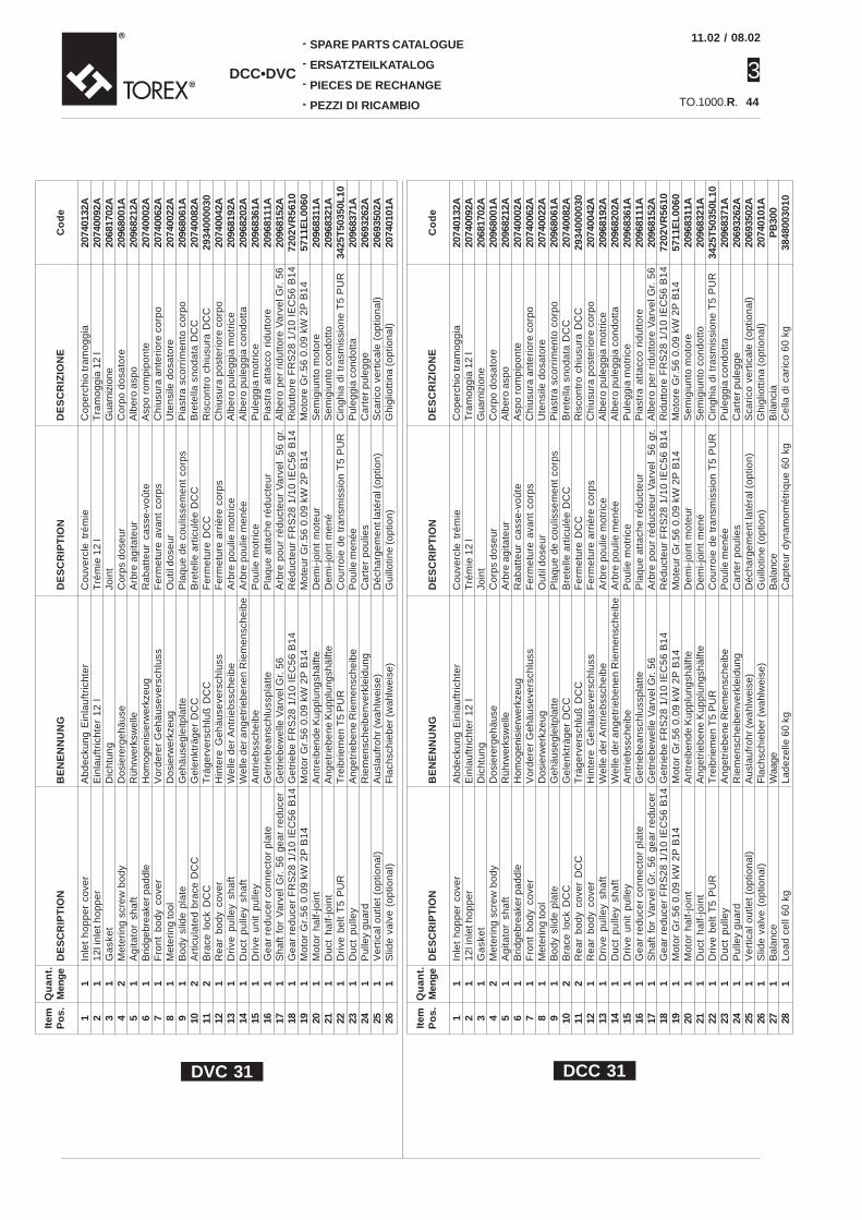
08.02
3TO.1000.R.
DCC•DVC
-
-
-
-
SPARE PARTS CATALOGUE
ERSATZTEILKATALOG
PIECES DE RECHANGE
PEZZI DI RICAMBIO 44
DE
SC
RIZ
ION
E
Cop
erch
io tr
amog
gia
Tra
mog
gia
12 l
Gua
rniz
ione
Cor
po d
osat
ore
Alb
ero
aspo
Asp
o ro
mpi
pont
eC
hius
ura
ante
rior
e co
rpo
Ute
nsile
dos
ator
eP
iast
ra s
corr
imen
to c
orpo
Bre
tella
sno
data
DC
CR
isco
ntro
chi
usur
a D
CC
Chi
usur
a po
ster
iore
cor
poA
lber
o pu
legg
ia m
otri
ceA
lber
o pu
legg
ia c
ondo
tta
Pul
eggi
a m
otri
ceP
iast
ra a
ttac
co r
idut
tore
Alb
ero
per
ridu
ttor
e V
arve
l Gr.
56
Rid
utto
re F
RS
28 1
/10
IEC
56 B
14M
otor
e G
r.56
0.0
9 kW
2P
B14
Sem
igiu
nto
mot
ore
Sem
igiu
nto
cond
otto
Cin
ghia
di t
rasm
issi
one
T5
PU
RP
uleg
gia
cond
otta
Car
ter
pule
gge
Sca
rico
ver
tical
e (o
ptio
nal)
Ghi
glio
ttin
a (o
ptio
nal)
Co
de
2074
0132
A20
7400
92A
2068
1702
A20
9680
01A
2096
8212
A20
7400
02A
2074
0062
A20
7400
22A
2096
8061
A20
7400
82A
2934
0000
3020
7400
42A
2096
8192
A20
9682
02A
2096
8361
A20
9681
11A
2096
8152
A72
02V
R56
1057
11E
L00
6020
9683
11A
2096
8321
A34
25T
5035
0L10
2096
8371
A20
6932
62A
2069
3502
A20
7401
01A
BE
NE
NN
UN
G
Abd
ecku
ng E
inla
uftr
icht
erE
inla
uftr
icht
er 1
2 l
Dic
htun
gD
osie
rerg
ehäu
seR
ührw
erks
wel
leH
omog
enis
ierw
erkz
eug
Vor
dere
r G
ehäu
seve
rsch
luss
Dos
ierw
erkz
eug
Geh
äuse
glei
tpla
tteG
elen
kträ
ger
DC
CT
räge
rver
schl
uß D
CC
Hin
tere
Geh
äuse
vers
chlu
ssW
elle
der
Ant
rieb
ssch
eibe
Wel
le d
er a
nget
rieb
enen
Rie
men
sche
ibe
Ant
rieb
ssch
eibe
Get
rieb
eans
chlu
sspl
atte
Get
rieb
ewel
le V
arve
l Gr.
56
Get
rieb
e F
RS
28 1
/10
IEC
56 B
14M
otor
Gr.
56 0
.09
kW 2
P B
14A
ntre
iben
de K
uppl
ungs
hälft
eA
nget
riebe
ne K
uppl
ungs
hälft
eT
reib
riem
en T
5 P
UR
Ang
etrie
bene
Rie
men
sche
ibe
Rie
men
sche
iben
verk
leid
ung
Aus
lauf
rohr
(wah
lwei
se)
Fla
chsc
hieb
er (w
ahlw
eise
)
DE
SC
RIP
TIO
N
Inle
t ho
pper
cov
er12
l inl
et h
oppe
rG
ask
et
Met
erin
g sc
rew
bod
yA
gita
tor
sha
ftB
ridge
brea
ker p
addl
eF
ront
bod
y co
ver
Met
erin
g to
olB
ody
slid
e pl
ate
Art
icul
ated
bra
ce D
CC
Bra
ce l
ock
DC
CR
ear
body
cov
erD
rive
pu
lley
sha
ftD
uct
pu
lley
sha
ftD
rive
uni
t pu
lley
Gea
r re
duce
r co
nnec
tor
plat
eS
haft
for
Var
vel
Gr.
56
gear
red
ucer
Gea
r re
duce
r F
RS
28 1
/10
IEC
56 B
14M
otor
Gr.
56 0
.09
kW 2
P B
14M
otor
hal
f-jo
int
Duc
t ha
lf-jo
int
Dri
ve b
elt
T5
PU
RD
uct
pulle
yP
ulle
y gu
ard
Ver
tical
out
let (
optio
nal)
Slid
e va
lve
(opt
iona
l)
DE
SC
RIP
TIO
N
Cou
verc
le t
rém
ieT
rém
ie 1
2 l
Join
tC
orps
dos
eur
Arb
re a
gita
teur
Rab
atte
ur c
asse
-voû
teF
erm
etur
e av
ant
corp
sO
util
dose
urP
laqu
e de
cou
lisse
men
t co
rps
Bre
telle
art
icul
ée D
CC
Fer
met
ure
DC
CF
erm
etur
e ar
rièr
e co
rps
Arb
re p
oulie
mot
rice
Arb
re p
oulie
men
éeP
oulie
mot
rice
Pla
que
atta
che
rédu
cteu
rA
rbre
pou
r ré
duct
eur
Var
vel
56 g
r.R
éduc
teur
FR
S28
1/1
0 IE
C56
B14
Mot
eur
Gr.
56 0
.09
kW 2
P B
14D
emi-
join
t m
oteu
rD
emi-
join
t m
ené
Cou
rroi
e de
tra
nsm
issi
on T
5 P
UR
Pou
lie m
enée
Car
ter
poul
ies
Déc
harg
emen
t lat
éral
(opt
ion)
Gui
llotin
e (o
ptio
n)
Item
Po
s. 1 2 3 4 5 6 7 8 9 10 11 12 13 14 15 16 17 18 19 20 21 22 23 24 25 26
Qu
ant.
Men
ge
1 1 1 2 1 1 1 1 1 2 2 1 1 1 1 1 1 1 1 1 1 1 1 1 1 1
DE
SC
RIZ
ION
E
Cop
erch
io tr
amog
gia
Tra
mog
gia
12 l
Gua
rniz
ione
Cor
po d
osat
ore
Alb
ero
aspo
Asp
o ro
mpi
pont
eC
hius
ura
ante
rior
e co
rpo
Ute
nsile
dos
ator
eP
iast
ra s
corr
imen
to c
orpo
Bre
tella
sno
data
DC
CR
isco
ntro
chi
usur
a D
CC
Chi
usur
a po
ster
iore
cor
poA
lber
o pu
legg
ia m
otri
ceA
lber
o pu
legg
ia c
ondo
tta
Pul
eggi
a m
otri
ceP
iast
ra a
ttac
co r
idut
tore
Alb
ero
per
ridu
ttor
e V
arve
l Gr.
56
Rid
utto
re F
RS
28 1
/10
IEC
56 B
14M
otor
e G
r.56
0.0
9 kW
2P
B14
Sem
igiu
nto
mot
ore
Sem
igiu
nto
cond
otto
Cin
ghia
di t
rasm
issi
one
T5
PU
RP
uleg
gia
cond
otta
Car
ter
pule
gge
Sca
rico
ver
tical
e (o
ptio
nal)
Ghi
glio
ttin
a (o
ptio
nal)
Bila
ncia
Cel
la d
i car
ico
60 k
g
Co
de
2074
0132
A20
7400
92A
2068
1702
A20
9680
01A
2096
8212
A20
7400
02A
2074
0062
A20
7400
22A
2096
8061
A20
7400
82A
2934
0000
3020
7400
42A
2096
8192
A20
9682
02A
2096
8361
A20
9681
11A
2096
8152
A72
02V
R56
1057
11E
L00
6020
9683
11A
2096
8321
A34
25T
5035
0L10
2096
8371
A20
6932
62A
2069
3502
A20
7401
01A
PB
300
3848
0030
10
BE
NE
NN
UN
G
Abd
ecku
ng E
inla
uftr
icht
erE
inla
uftr
icht
er 1
2 l
Dic
htun
gD
osie
rerg
ehäu
seR
ührw
erks
wel
leH
omog
enis
ierw
erkz
eug
Vor
dere
r G
ehäu
seve
rsch
luss
Dos
ierw
erkz
eug
Geh
äuse
glei
tpla
tteG
elen
kträ
ger
DC
CT
räge
rver
schl
uß D
CC
Hin
tere
Geh
äuse
vers
chlu
ssW
elle
der
Ant
rieb
ssch
eibe
Wel
le d
er a
nget
rieb
enen
Rie
men
sche
ibe
Ant
rieb
ssch
eibe
Get
rieb
eans
chlu
sspl
atte
Get
rieb
ewel
le V
arve
l Gr.
56G
etri
ebe
FR
S28
1/1
0 IE
C56
B14
Mot
or G
r.56
0.0
9 kW
2P
B14
Ant
reib
ende
Kup
plun
gshä
lfte
Ang
etrie
bene
Kup
plun
gshä
lfte
Tre
ibrie
men
T5
PU
RA
nget
riebe
ne R
iem
ensc
heib
eR
iem
ensc
heib
enve
rkle
idun
gA
usla
ufro
hr (w
ahlw
eise
)F
lach
schi
eber
(wah
lwei
se)
Waa
geLa
deze
lle 6
0 kg
DE
SC
RIP
TIO
N
Inle
t ho
pper
cov
er12
l inl
et h
oppe
rG
ask
et
Met
erin
g sc
rew
bod
yA
gita
tor
sha
ftB
ridge
brea
ker p
addl
eF
ront
bod
y co
ver
Met
erin
g to
olB
ody
slid
e pl
ate
Bra
ce l
ock
DC
CR
ear
body
cov
er D
CC
Rea
r bo
dy c
over
Dri
ve p
ulle
y sh
aft
Du
ct p
ulle
y sh
aft
Dri
ve u
nit
pulle
yG
ear
redu
cer
conn
ecto
r pl
ate
Sha
ft fo
r V
arve
l G
r. 56
gea
r re
duce
rG
ear
redu
cer
FR
S28
1/1
0 IE
C56
B14
Mot
or G
r.56
0.0
9 kW
2P
B14
Mot
or h
alf-
join
tD
uct
half-
join
tD
rive
bel
t T
5 P
UR
Duc
t pu
lley
Pul
ley
guar
dV
ertic
al o
utle
t (op
tiona
l)S
lide
valv
e (o
ptio
nal)
Bal
ance
Load
cel
l 60
kg
DE
SC
RIP
TIO
N
Cou
verc
le t
rém
ieT
rém
ie 1
2 l
Join
tC
orps
dos
eur
Arb
re a
gita
teur
Rab
atte
ur c
asse
-voû
teF
erm
etur
e av
ant
corp
sO
util
dose
urP
laqu
e de
cou
lisse
men
t co
rps
Bre
telle
art
icul
ée D
CC
Fer
met
ure
DC
CF
erm
etur
e ar
rièr
e co
rps
Arb
re p
oulie
mot
rice
Arb
re p
oulie
men
éeP
oulie
mot
rice
Pla
que
atta
che
rédu
cteu
rA
rbre
pou
r ré
duct
eur
Var
vel
56 g
r.R
éduc
teur
FR
S28
1/1
0 IE
C56
B14
Mot
eur
Gr.
56 0
.09
kW 2
P B
14D
emi-
join
t m
oteu
rD
emi-
join
t m
ené
Cou
rroi
e de
tra
nsm
issi
on T
5 P
UR
Pou
lie m
enée
Car
ter
poul
ies
Déc
harg
emen
t lat
éral
(opt
ion)
Gui
llotin
e (o
ptio
n)B
alan
ceC
apte
ur d
ynam
omét
riqu
e 60
kg
Item
Po
s. 1 2 3 4 5 6 7 8 9 10 11 12 13 14 15 16 17 18 19 20 21 22 23 24 25 26 27 28
Qu
ant.
Men
ge
1 1 1 2 1 1 1 1 1 2 2 1 1 1 1 1 1 1 1 1 1 1 1 1 1 1 1 1
DVC 31 DCC 31
11.02 /

3
08.02
TO.1000.R.
-
-
-
-
SPARE PARTS CATALOGUE
ERSATZTEILKATALOG
PIECES DE RECHANGE
PEZZI DI RICAMBIO
DCC•DVC
45
20
•
19
•
22
•
23
•
24
•
25
•
21
•
1
•
2
•
3
•
4
•
6
•
26
•
27
•
17
•
16
•
15
•
14
•
13
•
18
•
12•
11
•
8
•
7•
9•
DVC 32
5
•
10•
11.02 /

08.02
3TO.1000.R.
DCC•DVC
-
-
-
-
SPARE PARTS CATALOGUE
ERSATZTEILKATALOG
PIECES DE RECHANGE
PEZZI DI RICAMBIO 4619
•
20
•
21
•
22
•23
•
24
•
25 •
1
•
2
•
3
•
4
•
5
•
26
•
27
•
18
•
17
•
16
•
15
•
14
•
13
•
12
•
11
•
9•
8•
7•
29•
28•
DCC 32
10
•
6
•
11.02 /

3
08.02
TO.1000.R.
-
-
-
-
SPARE PARTS CATALOGUE
ERSATZTEILKATALOG
PIECES DE RECHANGE
PEZZI DI RICAMBIO
DCC•DVC
47
DE
SC
RIZ
ION
EC
oper
chio
tram
oggi
aT
ram
oggi
a 12
lG
uarn
izio
neC
orpo
dos
ator
eA
lber
o as
poA
spo
rom
pipo
nte
Chi
usur
a an
teri
ore
corp
oU
tens
ile d
osat
ore
Pia
stra
sco
rrim
ento
cor
poB
rete
lla s
noda
ta D
CC
Ris
cont
ro c
hius
ura
DC
CC
hius
ura
post
erio
re c
orpo
Tend
icin
ghia
Alb
ero
pule
ggia
mot
rice
Alb
ero
pule
ggia
con
dott
aP
uleg
gia
mot
rice
Pia
stra
att
acco
rid
utto
reA
lber
o pe
r ri
dutt
ore
Var
vel G
r. 5
6R
idut
tore
FR
S28
1/1
0 IE
C56
B14
Mot
ore
Gr.
56 0
.09
kW 2
P B
14S
emig
iunt
o m
otor
eS
emig
iunt
o co
ndot
toC
ingh
ia d
i tra
smis
sion
e T
5 P
UR
Pul
eggi
a co
ndot
taC
arte
r pu
legg
eS
cari
co v
ertic
ale
(opt
iona
l)G
higl
iott
ina
(opt
iona
l)
Co
de
2074
0132
A20
7400
92A
2068
1702
A20
9680
01A
2096
8212
A20
7400
02A
2074
0072
A20
7400
32A
2096
8061
A20
7400
82A
2934
0000
3020
7400
52A
2074
0201
A20
9681
92A
2096
8202
A20
9683
61A
2096
8121
A20
9681
52A
7202
VR
5610
5711
EL
0060
2096
8311
A20
9683
21A
3425
T50
350L
1020
9683
71A
2069
3262
A20
7401
42A
2074
0122
A
BE
NE
NN
UN
GA
bdec
kung
Ein
lauf
tric
hter
Ein
lauf
tric
hter
12
lD
icht
ung
Dos
iere
rgeh
äuse
Rüh
rwer
ksw
elle
Hom
ogen
isie
rwer
kzeu
gV
orde
rer
Geh
äuse
vers
chlu
ssD
osie
rwer
kzeu
gG
ehäu
segl
eitp
latte
Gel
enkt
räge
r D
CC
Trä
gerv
ersc
hluß
DC
CH
inte
re G
ehäu
seve
rsch
luss
Hin
tere
Geh
äuse
vers
chlu
ssW
elle
der
Ant
rieb
ssch
eibe
Wel
le d
er a
nget
rieb
enen
Rie
men
sche
ibe
Ant
rieb
ssch
eibe
Get
rieb
eans
chlu
sspl
atte
Get
rieb
ewel
le V
arve
l Gr.
56G
etri
ebe
FR
S28
1/1
0 IE
C56
B14
Mot
or G
r.56
0.0
9 kW
2P
B14
Ant
reib
ende
Kup
plun
gshä
lfte
Ang
etrie
bene
Kup
plun
gshä
lfte
Tre
ibrie
men
T5
PU
RA
nget
riebe
ne R
iem
ensc
heib
eR
iem
ensc
heib
enve
rkle
idun
gA
usla
ufro
hr (w
ahlw
eise
)F
lach
schi
eber
(wah
lwei
se)
DE
SC
RIP
TIO
NIn
let
hopp
er c
over
12l i
nlet
hop
per
Ga
ske
tM
eter
ing
scre
w b
ody
Ag
itato
r sh
aft
Brid
gebr
eake
r pad
dle
Fro
nt b
ody
cove
rM
eter
ing
tool
Bod
y sl
ide
plat
eA
rtic
ulat
ed b
race
DC
CB
race
loc
k D
CC
Rea
r bo
dy c
over
Bel
t tig
hten
erD
rive
pu
lley
sha
ftD
uct
pu
lley
sha
ftD
rive
uni
t pu
lley
Gea
r re
duce
r co
nnec
tor
plat
eS
haft
for
Var
vel
Gr.
56
gear
red
ucer
Gea
r re
duce
r F
RS
28 1
/10
IEC
56 B
14M
otor
Gr.
56 0
.09
kW 2
P B
14M
otor
hal
f-jo
int
Duc
t ha
lf-jo
int
Dri
ve b
elt
T5
PU
RD
uct
pulle
yP
ulle
y gu
ard
Ver
tical
out
let (
optio
nal)
Slid
e va
lve
(opt
iona
l)
DE
SC
RIP
TIO
NC
ouve
rcle
tré
mie
Tré
mie
12
lJo
int
Cor
ps d
oseu
rA
rbre
agi
tate
urR
abat
teur
cas
se-v
oûte
Fer
met
ure
avan
t co
rps
Out
il do
seur
Pla
que
de c
oulis
sem
ent
corp
sB
rete
lle a
rtic
ulée
DC
CF
erm
etur
e D
CC
Fer
met
ure
arri
ère
corp
sTe
ndeu
r de
cour
roie
Arb
re p
oulie
mot
rice
Arb
re p
oulie
men
éeP
oulie
mot
rice
Pla
que
atta
che
rédu
cteu
rA
rbre
pou
r ré
duct
eur
Var
vel
56 g
r.R
éduc
teur
FR
S28
1/1
0 IE
C56
B14
Mot
eur
Gr.
56 0
.09
kW 2
P B
14D
emi-
join
t m
oteu
rD
emi-
join
t m
ené
Cou
rroi
e de
tra
nsm
issi
on T
5 P
UR
Pou
lie m
enée
Car
ter
poul
ies
Déc
harg
emen
t lat
éral
(opt
ion)
Gui
llotin
e (o
ptio
n)
Item
Po
s. 1 2 3 4 5 6 7 8 9 10 11 12 13 14 15 16 17 18 19 20 21 22 23 24 25 26 27
Qu
ant.
Men
ge
1 1 1 2 1 1 1 1 1 2 2 1 1 1 1 1 1 1 1 1 1 1 1 1 1 1 1
DE
SC
RIZ
ION
EC
oper
chio
tram
oggi
aT
ram
oggi
a 12
lG
uarn
izio
neC
orpo
dos
ator
eA
lber
o as
poA
spo
rom
pipo
nte
Chi
usur
a an
teri
ore
corp
oU
tens
ile d
osat
ore
Pia
stra
sco
rrim
ento
cor
poB
rete
lla s
noda
ta D
CC
Ris
cont
ro c
hius
ura
DC
CC
hius
ura
post
erio
re c
orpo
Tend
icin
ghia
Alb
ero
pule
ggia
mot
rice
Alb
ero
pule
ggia
con
dott
aP
uleg
gia
mot
rice
Pia
stra
att
acco
rid
utto
reA
lber
o pe
r ri
dutt
ore
Var
vel G
r. 5
6R
idut
tore
FR
S28
1/1
0 IE
C56
B14
Mot
ore
Gr.
56 0
.09
kW 2
P B
14S
emig
iunt
o m
otor
eS
emig
iunt
o co
ndot
toC
ingh
ia d
i tra
smis
sion
e T
5 P
UR
Pul
eggi
a co
ndot
taC
arte
r pu
legg
eS
cari
co v
ertic
ale
(opt
iona
l)G
higl
iott
ina
(opt
iona
l)B
ilanc
iaC
ella
di c
aric
o 60
kg
Co
de
2074
0132
A20
7400
92A
2068
1702
A20
9680
11A
2096
8212
A20
7400
02A
2074
0072
A20
7400
32A
2096
8061
A20
7400
82A
2934
0000
3020
7400
52A
2074
0201
A20
9681
92A
2096
8202
A20
9683
61A
2096
8121
A20
9681
52A
7202
VR
5610
5711
EL
0060
2096
8311
A20
9683
21A
3425
T50
350L
1020
9683
71A
2069
3262
A20
7401
42A
2074
0122
AP
B30
038
4800
3010
BE
NE
NN
UN
GA
bdec
kung
Ein
lauf
tric
hter
Ein
lauf
tric
hter
12
lD
icht
ung
Dos
iere
rgeh
äuse
Rüh
rwer
ksw
elle
Hom
ogen
isie
rwer
kzeu
gV
orde
rer
Geh
äuse
vers
chlu
ssD
osie
rwer
kzeu
gG
ehäu
segl
eitp
latte
Gel
enkt
räge
r D
CC
Trä
gerv
ersc
hluß
DC
CH
inte
re G
ehäu
seve
rsch
luss
Hin
tere
Geh
äuse
vers
chlu
ssW
elle
der
Ant
rieb
ssch
eibe
Wel
le d
er a
nget
rieb
enen
Rie
men
sche
ibe
Ant
rieb
ssch
eibe
Get
rieb
eans
chlu
sspl
atte
Get
rieb
ewel
le V
arve
l Gr.
56G
etri
ebe
FR
S28
1/1
0 IE
C56
B14
Mot
or G
r.56
0.0
9 kW
2P
B14
Ant
reib
ende
Kup
plun
gshä
lfte
Ang
etrie
bene
Kup
plun
gshä
lfte
Tre
ibrie
men
T5
PU
RA
nget
riebe
ne R
iem
ensc
heib
eR
iem
ensc
heib
enve
rkle
idun
gA
usla
ufro
hr (w
ahlw
eise
)F
lach
schi
eber
(wah
lwei
se)
Waa
geLa
deze
lle 6
0 kg
DE
SC
RIP
TIO
NIn
let
hopp
er c
over
12l i
nlet
hop
per
Ga
ske
tM
eter
ing
scre
w b
ody
Ag
itato
r sh
aft
Brid
gebr
eake
r pad
dle
Fro
nt b
ody
cove
rM
eter
ing
tool
Bod
y sl
ide
plat
eA
rtic
ulat
ed b
race
DC
CB
race
loc
k D
CC
Rea
r bo
dy c
over
Bel
t tig
hten
erD
rive
pu
lley
sha
ftD
uct
pu
lley
sha
ftD
rive
uni
t pu
lley
Gea
r re
duce
r co
nnec
tor
plat
eS
haft
for
Var
vel
Gr.
56
gear
red
ucer
Gea
r re
duce
r F
RS
28 1
/10
IEC
56 B
14M
otor
Gr.
56 0
.09
kW 2
P B
14M
otor
hal
f-jo
int
Duc
t ha
lf-jo
int
Dri
ve b
elt
T5
PU
RD
uct
pulle
yP
ulle
y gu
ard
Ver
tical
out
let (
optio
nal)
Slid
e va
lve
(opt
iona
l)B
alan
ceLo
ad c
ell 6
0 kg
DE
SC
RIP
TIO
NC
ouve
rcle
tré
mie
Tré
mie
12
lJo
int
Cor
ps d
oseu
rA
rbre
agi
tate
urR
abat
teur
cas
se-v
oûte
Fer
met
ure
avan
t co
rps
Out
il do
seur
Pla
que
de c
oulis
sem
ent
corp
sB
rete
lle a
rtic
ulée
DC
CF
erm
etur
e D
CC
Fer
met
ure
arri
ère
corp
sTe
ndeu
r de
cour
roie
Arb
re p
oulie
mot
rice
Arb
re p
oulie
men
éeP
oulie
mot
rice
Pla
que
atta
che
rédu
cteu
rA
rbre
pou
r ré
duct
eur
Var
vel
56 g
r.R
éduc
teur
FR
S28
1/1
0 IE
C56
B14
Mot
eur
Gr.
56 0
.09
kW 2
P B
14D
emi-
join
t m
oteu
rD
emi-
join
t m
ené
Cou
rroi
e de
tra
nsm
issi
on T
5 P
UR
Pou
lie m
enée
Car
ter
poul
ies
Déc
harg
emen
t lat
éral
(opt
ion)
Gui
llotin
e (o
ptio
n)B
alan
ceC
apte
ur d
ynam
omét
riqu
e 60
kg
Item
Po
s. 1 2 3 4 5 6 7 8 9 10 11 12 13 14 15 16 17 18 19 20 21 22 23 24 25 26 27 28 29
Qu
ant.
Men
ge
1 1 1 2 1 1 1 1 1 2 2 1 1 1 1 1 1 1 1 1 1 1 1 1 1 1 1 1 1
DVC 32 DCC 32
11.02 /