
Manual WPIL Vertical Turbine Pumps
57
INSTALLATION, OPERATION & MAINTENANCE INSTRUCTIONS Product, Oil, Grease & Water Flush Lubricated Construction Pumps VERTICAL TURBINE PUMPS Juan Gutemberg 438 / G 7 y 8 · Tel. (56-55) 556606 · Fax. (56-55) 556607 E - mail: [email protected] · Antofagasta Chile
-
Upload
david-osores -
Category
Documents
-
view
1.305 -
download
101
Transcript of Manual WPIL Vertical Turbine Pumps
INSTALLATION, OPERATION & MAINTENANCE INSTRUCTIONS
Product, Oil, Grease & Water Flush Lubricated Construction Pumps
VERTICAL TURBINE PUMPS
Juan Gutemberg 438 / G 7 y 8 · Tel. (56-55) 556606 · Fax. (56-55) 556607E - mail: [email protected] · Antofagasta Chile
Installation and Operation Manual for Vertical Turbine Pumps
WPIL formerly Worthington Pump India Ltd.
NOTICEThis WPIL Pumps manual provides instructions for installing, operating, and maintaining our vertical turbine pumps. These instructions are written only for those who have a working knowledge of vertical pumps and a familiarity with both the terminology and proper field practices used in the vertical pump industry. Cautions and warnings are included, but they are not substitutes for the careful work of the experienced.
By furnishing this manual, WPIL (WM Group Member). does not accept liability for successful pump installation, operation, or maintenance; that liability belongs to those who actually install, operate, and maintain the pump.
Although we used the most current information available at the time this manual was published, all information contained herein is subject to change without notice. We made every effort to avoid errors, but we cannot guarantee that this manual is error-free.
We appreciate your interest in our product. If you have questions about the contents of this manual, please contact VMS Engineering and Support Department at your place in Antofagasta,Chile.
Sales and Service Centers
Juan Gutemberg 438 / G 7 y 8 Tel. (56-55) 556606 · Fax. (56-55) 556607
E - mail: [email protected] www.vms.cl
Antofagasta Chile
Installation and Operation Manual for Vertical Turbine Pumps
WPIL formerly Worthington Pump India Ltd. 1
TABLE OF CONTENTS (TOC 1–6)
EGAP NOITCUDORTNI 1 NOITCES
1-1 INTRODUCTION…………………………………………………………………………………….. 11-2 Briefing………………………………………………………………………………………………... 1 1-3 Assistance Information & Warranty Warning……………………………………………………... 1 1-4 RECEIVING AND CHECKING…………………………………………………………………….. 11-5 Unloading and Inspection…………………………………………………………………………… 1 1-6 Shortages and Damages…………………………………………………………………………… 1 1-7 SAFETY PRECAUTIONS………………………………………………………………………….. 11-8 Personnel Injury Prevention………………………………………………………………………… 1 1-9 REQUIRED MATERIALS AND EQUIPMENT……………………………………………………. 11-10 Briefing………………………………………………………………………………………………... 1 A. Lifting Equipment 1 B. Bulk Material 1 C. Hand Tools 1 & 2 D. Optional Tools 2
2 EGAROTS 2 NOITCES
2-1 STORAGE……………………………………………………………………………………………. 22-2 Environmental Briefing………...………………………………………………………….………… 2 2-3 STORAGE PREPARATION………………………………………………………………………... 22-4 Definition………..…………………………………………………………………………………….. 2 2-5 Shortage Claims………...…………………………………………………………………………… 2 2-6 RECOMMENDED STORAGE PROCEDURE (ONE MONTH OR LESS AFTER
DELIVERY)…………………………………………………………………………………………… 22-7 One Month or Less……………….………………………………………………………………….. 2 2-8 RECOMMENDED STORAGE PROCEDURE (MORE THAN ONE MONTH AFTER
DELIVERY)…………………………………………………………………………………………… 22-9 Assembled Pumps…………………………………………………………………………………... 2 2-10 Disassembled Pumps……………………………………………………………………………….. 2
3 NOITPIRCSED LARENEG 3 NOITCES
3-1 GENERAL DESCRIPTION & INFORMATION…………………………………………………… 33-2 Major Sub-Assemblies………………………………………………………………………………. 3 3-3 DRIVERS……………………………………………………………………………………………... 33-4 Common Type Drivers………………………………………………………………………………. 3 3-5 DISCHARGE HEAD ASSEMBLY…………………………………………………………………. 33-6 Designs of the Discharge Head….………………………………………………………………… 3 3-7 COLUMN ASSEMBLY……………………………………………………………………………… 43-8 Designs of the Column……………………………………………………………………………… 4 3-9 BOWL ASSEMBLY……………………………………………………………………...………….. 43-10 Designs of the Bowl Assembly…...………………………………………………………………… 4 3-11 PUMP BEARING LUBRICATION CONSTRUCTIONS……………………………...………….. 4
4 detacirbuL tcudorP fo noitinifeD .A 4 detacirbuL hsulfretaW fo noitinifeD .B 4 detacirbuL esaerG fo noitinifeD .C 4 detacirbuL liO fo noitinifeD .D
Installation and Operation Manual for Vertical Turbine Pumps
WPIL formerly Worthington Pump India Ltd.2
21 NOITADNUOF 4 NOITCES
4-1 PREPARING THE FOUNDATION………………………………………………………………… 124-2 Foundation Design…………………………………………………………………………………... 12 4-3 Foundation Types- Concrete.………………………………………………………………………. 12 4-4 FoundationTypes- I-Beams, Timbers………..…………………………………………………….. 12 4-5 INSTALLATION……………………………………………………………………………………… 124-6 Sub-Base Leveling and Grout Type……………………………………………………………….. 12 4-7 Barrel Leveling and Grout Type……………………………………………………………………. 12
31 NOITALLATSNI PMUP 5 NOITCES
5-1 NECESSARY STEPS BEFORE PUMP INSTALLATION………………………………………. 135-2 Well Examination…………………………………………………………………………………….. 13 5-3 Inspection Instructions and Procedure….………………………………………………………… 13 5-4 INSTALLING A PARTIALLY ASSEMBLED PUMP…………………………………………….. 135-5 Briefing and Procedure……………………………………………………………………………… 13
SECTION 6 INSTALLING THE STRAINER ASSEMBLY (OPTIONAL) 14
6-1 BASKET & CONE STRAINERS…………………………………………………………………… 14 6-2 Installation Instructions……….……………………………………………………………………... 14 6-3 Cone Strainer Procedure……………………………………………………………………………. 14 6-4 Cone Strainer with Suction Pipe Procedure………………………………………………………. 14 6-5 Basket Strainer—Clip on Type Procedure………………………………………………………... 14 6-6 Basket Strainer/Threaded Type, Briefing and Procedure….……………………………………. 14
SECTION 7 INSTALLING THE BOWL AND OPEN LINESHAFT ASSEMBLY 15
7-1 BOWL ASSEMBLY…………………………………………………………………………………. 157-2 Installation Instructions……………………………………………………………………………… 15 7-3 THREADED OR FLANGED COLUMN ASSEMBLY …………………………..……………….. 157-4 Installation Procedure……………………………………………………………………………….. 15 7-5 Large Flanged Column/Fabricated Retainer/Threaded Coupling Instruction and Procedure.. 15 7-6 Large Flanged Column/Fabricated Retainer/Thrust Stud Coupling Instruction and
Procedure…………………………………………………………………………………………….. 167-7 Thrust Stud Coupling Instruction and Procedure...………………………………………………. 16 7-8 Lineshaft Sleeve (Optional) Instruction and Procedure...……………………………………….. 16 7-9 Flanged Column/”O”-Ring Instructions……………………………………………………………. 16 7-10 Top Column/Threaded or Flanged Procedure……………………………………………………. 16
SECTION 8 INSTALLING THE BOWL AND ENCLOSED LINESHAFT ASSEMBLY 16
8-1 BOWL ASSEMBLY…………………………………………………………………………………. 178-2 Installation Instructions……………………………………………………………………………… 17 8-3 Optional External Grease Line Instructions………………………………………………………. 17 8-4 THREADED OR FLANGED COLUMN ASSEMBLY……………………………………………. 178-5 Installation Procedure……………………………………………………………………………….. 17 8-6 Thrust Stud Coupling Instruction and Procedure…...……………………………………………. 17 8-7 Top Column/Threaded or Flanged Procedure……………………………………………………. 17 & 18 8-8 Top Column/Flanged/Thrust Stud Coupling Procedure…………………………………………. 18 8-9 SUB-BASE (OPTIONAL)…………………………………………………………………………… 188-10 Installation Instructions……………………………………………………………………………… 18
Installation and Operation Manual for Vertical Turbine Pumps
WPIL formerly Worthington Pump India Ltd. 3
8-11 BELOW BASE DISCHARGE-BASE PLATE ASSEMBLY, SPECIAL INSTRUCTIONS…… 18
SECTION 9 INSTALLING THE DISCHARGE HEAD ASSEMBLY (OPEN LINESHAFT) 18
9-1 DISCHARGE HEADS……………………………………………………………………………….. 18 9-2 Type A or L Discharge Head Procedure.…………………………………………………………. 19 9-3 Type AB Discharge Head Procedure…………………………………………………………….. 19 9-4 Large Fabricated Head Procedure………………………………………………………………... 19 9-5 Fabricated Barrel Procedure……………………………………………………………………….. 19 9-6 PACKING BOXES……………………………………………………………………….………….. 199-7 Six Ring Packing Box Procedure..………………………………………………………………… 19 9-8 By-Pass Packing Box Procedure ………………………………………………………………….. 19 9-9 Packing Box Sleeve Procedure……………...……………………………………………………. 20 9-10 MECHANICAL SEALS……………………………………………………………………………… 20
SECTION 10 INSTALLING THE DISCHARGE HEAD ASSEMBLY (ENCLOSED LINESHAFT) 21
10-1 DISCHARGE HEADS……………………………………………………………………………….. 2110-2 Type A or L Discharge Head Procedure.…………………………………………………………. 21 10-3 Type AB Discharge Head Procedure…………………………………………………………….. 21 10-4 Large Fabricated Head Procedure………………………………………………………………... 21 10-5 TUBE TENSION NUTS……………………………………………………………………….…….. 2110-6 Enclosing Tube Oil Lubricated Procedure.……………………………………………………….. 21 10-7 Enclosing Tube Grease Lubricated Procedure…………………………………………………… 21 10-8 Enclosing Tube Waterflush Lubricated Procedure…………….………………………………… 21 10-9 Enclosing Tube Waterflush With Sleeve Procedure……………………………………………... 22
22 )SHV( REVIRD EHT GNILLATSNI 11 NOITCES
11-1 HOLLOW SHAFT DRIVES……………………………………………………………………….… 2211-2 Installing the Driver Procedure……………………………………………………………………... 22 11-3 Pump Alignment Procedure………………………………………………………………………… 22 11-4 Driver Electrical Connection Procedure……..……………………………………………………. 22 11-5 Impeller Adjustment Procedure…………………………………………………………………….. 22 & 23 11-6 HOLLW SHAFT DRIVES/TWO PIECE HEADSHAFT AND THREADED COUPLING 2311-7 Installing the Driver Procedure……….…………………………………………………………….. 23 11-8 Driver Electrical Connection Procedure…………………………………………………………… 23 11-9 Pump Alignment Procedure………………………………………………………………………… 23 11-10 Impeller Adjustment Procedure…………………………………………………………………….. 23 11-11 HOLLOW SHAFT DRIVES/TWO PIECE HEADSHAFT /RIGID FLANGEDCOUPLING…… 2311-12 Installing the Driver, Electrical Connection, Pump Alignment and Impeller Adjustment
Procedure…………………………………………………………………………………………….. 23 & 24
42 )SSV( REVIRD EHT GNILLATSNI 21 NOITCES
12-1 SOLID SHAFT DRIVES/ADJUSTABLE FLANGED COUPLINGS……………………………. 2412-2 Installing the Driver and Flanged Coupling Procedure………………………...………………... 24 12-3 Driver Electrical Connection Procedure…………………………………………………………… 24 12-4 Impeller Adjustment Procedure…………………………………………………………………….. 24 12-5 Pump Alignment Procedure………………………………………………………………………… 24 12-6 Flanged Coupling/Short Spacer, Driver, Electrical Connection, Pump Alignment and
Impeller Adjustment Procedure…………………………………………………………………….. 2512-7 Flanged Coupling/Long Spacer, Driver, Electrical Connection, Pump Alignment and
Impeller Adjustment Procedure…………………………………………………………………….. 25
Installation and Operation Manual for Vertical Turbine Pumps
WPIL formerly Worthington Pump India Ltd.4
52 SEIROSSECCA GNILLATSNI 31 NOITCES
13-1 OILER ASSEMBLY FOR OIL LUBRICATED PUMPS, MANUAL OR SOLENOID……….… 2513-2 Installing Instructions………………………………………………………………………………… 25 & 26 13-3 AIRLINE AND GAUGE (OPTIONAL)……………………………………………………………... 2613-4 Installing Instructions………………………………………………………………………………… 26 13-5 PRE-LUBE TANK AND FITTING (OPTIONAL)…………………………………………………. 2613-6 Briefing and Installing Instructions…………………………………………………………………. 26
72 NOITAREPO DNA PU-TRATS PMUP 41 NOITCES
14-1 PRE-START PROCEDURE………………………………………………………………………... 2714-2 PRIMING (First Stage).…………………………………………………………………………….. 2814-3 PUMP START-UP (Product Lubricated)………………………………………………………… 2814-4 VHS or VSS Drive…………………………………………………………..……………………….. 28 14-5 IMPORTANT OPERATING GUIDELINES…………………………………………………….…. 2814-6 Guideline Instructions……………………………………………………………………………….. 28 14-7 LUBRICATION DURING OPERATION/PRODUCT LUBRICATED PUMPS………………… 2814-8 Stuffing Box…………………………………………………………………………………………... 28 & 29 14-9 Mechanical Seal …………………………………………………………………………………….. 29 14-10 Suction Bearing ……………………………………………………………………………………... 29 14-11 Suction Bearing Lubrication Chart…………………………………………………………………. 29 14-12 PUMP START-UP (Oil Lubricated)………………………………………………………………. 2914-13 VHS Drive…………………………………………………………………………………………….. 29 14-14 ADDITIONAL IMPORTANT OPERATING GUIDELINES………………………………………. 2914-15 Oil Lubricated Pumps………………………………………………………………………..……… 29 14-16 LUBRICATION DURING OPERATION/OIL LUBRICATED PUMPS…………………………. 2914-17 Lineshaft Lubricant …………….……………………………………………………………………. 29 14-18 Lineshaft Lubrication Chart…………………………………………………………………………. 29 & 30 14-19 Suction Bearing Lubricant…………………………………………………………………………... 30 14-20 PUMP START-UP & LUBRICATION DURING OPERATION/GREASE LUBRICATED….... 3014-21 VHS Drive…………………………………………………………………………………………….. 30 14-22 Lineshaft Lubricant…………………………………………………………………………………... 30 14-23 Grease Lubrication Chart…………………………………………………………………………… 30 14-24 Suction Bearing Lubricant…………………………………………………………………………... 30 14-25 PUMP START-UP & LUBRICATION DURING OPERATION/WATERFLUSH
LUBRICATED………………………………………………………………………………………... 3014-26 VHS Drive…………………………………………………………………………………………….. 30 14-27 Suction Bearing Lubricant…………………………………………………………………………... 30 14-28 RECOMMENDED SPARE PARTS………………………………………………………………... 3014-29 Ordering Procedure and Parts Subject to Most Wear…………………………………………… 30
SECTION 15 MAINTENANCE INSTRUCTIONS BOWL ASSEMBLY, LOCK COLLET CONSTRUCTION 31
15-1 VERTICAL TURBINE PUMP BOWL ASSEMBLY, PRODUCT LUBRICATED, ENCLOSED IMPELLER(S)………………………………………………………………………… 31
15-2 Assembly Procedure………………………………………………………………………………… 31 & 32 15-3 Disassembly Procedure…………………………………………………………………………….. 32 15-4 VERTICAL TURBINE PUMP BOWL ASSEMBLY, PRODUCT LUBRICATED, SEMI-
OPEN IMPELLER(S)………………………………………………………………………………... 3215-5 Assembly Procedure………………………………………………………………………………… 32 15-6 Disassembly Procedure…………………………………………………………………………….. 32 15-7 VERTICAL TURBINE PUMP BOWL ASSEMBLY, OIL LUBRICATED, ENCLOSED
IMPELLER(S)………………………………………………………………………………………... 3215-8 Assembly Procedure………………………………………………………………………………… 32 & 33 15-9 Disassembly Procedure…………………………………………………………………………….. 33
Installation and Operation Manual for Vertical Turbine Pumps
WPIL formerly Worthington Pump India Ltd. 5
15-10 VERTICAL TURBINE PUMP BOWL ASSEMBLY, OIL LUBRICATED, SEMI-OPEN IMPELLER(S)………………………………………………………………………………………... 34
15-11 Assembly Procedure………………………………………………………………………………… 34 15-12 Disassembly Procedure…………………………………………………………………………….. 34 15-13 VERTICAL TURBINE PUMP BOWL ASSEMBLY, GREASE LUBRICATED, ENCLOSED
OR SEMI-OPEN IMPELLER(S)……………………………………………………………………. 3415-14 Assembly and Disassembly Procedure…………………………………………………………… 34 15-15 VERTICAL TURBINE PUMP BOWL ASSEMBLY, WATERFLUSH LUBRICATED,
ENCLOSED OR SEMI-OPEN IMPELLER(S) SPECIAL INSTRUCTIONS…………………… 34
SECTION 16 MAINTENANCE INSTRUCTIONS BOWL ASSEMBLY, KEYED CONSTRUCTION 37
16-1 Thrust Ring Location Briefing………………………………………………………………………. 37 16-2 VERTICAL TURBINE PUMP BOWL ASSEMBLY, PRODUCT LUBRICATED,
ENCLOSED OR SEMI-OPEN IMPELLER(S)……………………………………………………. 3716-3 Assembly Procedure..……………………………………………………………………………….. 37 & 38 16-4 Disassembly Procedure.……………………………………………………………………………. 38 16-5 VERTICAL TURBINE PUMP BOWL ASSEMBLY, OIL LUBRICATED, ENCLOSED OR
SEMI-OPEN IMPELLER(S)…...………………………………………………………………….... 3816-6 Assembly Procedure..……………………………………………………………………………….. 38 & 39 16-7 Disassembly Procedure…………………………………………………………………………….. 39
SECTION 17 MAINTENANCE INSTRUCTIONS BOWL ASSEMBLY, ASSEMBLY & DISASSEMBLY 93 ”SLAICEPS“
17-1 “O” Ring Gasket(s)…………………………………………………………………………………... 39 17-2 Thrust Balanced Impeller(s)………………………………………………………………………… 39 17-3 Thrust Balanced Impeller(s)/”O” Rings……………………………………………………………. 39 17-4 Thrust Balanced Impeller(s)/Wear Ring(s)………………………………………………………... 40 17-5 Keyed Impeller(s)/Lock Collet(s)…………………………………………………………………… 40 17-6 Keyed Impeller(s)/Retaining Rings………………………………………………………………… 40 17-7 Bowl Wear Ring(s)…………………………………………………………………………………… 40
04 SNOITCURTSNI ECNANETNIAM EVITNEVERP 81 NOITCES
18-1 Preventive Maintenance Table…………………………………………………………………….. 40
SERVICE REPORT START-UP CHECK LIST…………………………………………………... 41VIBRATION SENSOR LOCATION ILLUSTRATION AND H.I.S. VIBRATION LIMIT CHARTS……………………………………………………………………………………………… 42
34 GNITOOHSELBUORT 91 NOITCES
19-1 Trouble Indicators, Possible Causes and Recommended Remedies Table………………... 43 & 44
TERMS AND CONDITONS OF SALE
Installation and Operation Manual for Vertical Turbine Pumps
WPIL formerly Worthington Pump India Ltd.6
LIST OF ASSEMBLY AND ILLUSTRATIONS (DRAWINGS)
EGAP GNIWARD FO NOITPIRCSED ERUGIF
A Bowl Assembly and Strainer………………………………………………………………………... 3 B Column Assembly……………………………………………………………………………………. 3 C Discharge Head Assembly………………………………………………………………………….. 3 D Driver………………………………………………………………………………………………….. 3 Oil Lubricated Deep Well with Cone Strainer…………………………………………………….. 3 E Packing Box………………………………………………………………………………………….. 4 F Enclosing Tube Waterflush…………….…………………………………………………………… 4 G Enclosing Tube Grease……………………………………………………………………………... 4 H Enclosing Tube Oil…………………………………………………………………………………... 4 Turbine Bowl Assembly—Product and Oil Lubricated—Lock Collet—Semi-Open and
Enclosed Impeller……………………………………………………………………………………. 5
Product Lubricated Column Assembly—Flanged and Threaded………………………………. 6 Oil Lubricated Column Assembly—Threaded and Flanged…………………………………….. 7 Product Lubricated Discharge Head Assembly…………………………………………………... 8 Oil Lubricated Discharge Head Assembly………………………………………………………… 9 Waterflush Pump Assembly………………………………………………………………………… 10
11 pmuP ebuL tcudorP lacipyT 4.1 Sub-base Installation………………………………………………………………………………… 12 4.2 Barrel Installation…………………………………………………………………………………….. 12 6.1 Cone Strainer Assembly…………………………………………………………………………….. 14 6.2 Cone Strainer with Suction Pipe Assembly……………………………………………………….. 14 6.3 Basket Strainer—Clip on Type Assembly…………………………………………………………. 14 6.4 Basket Strainer—Threaded Type Assembly……………………………………………………… 14 7.1 Threaded Coupling Assembly……………………………………………………………………… 15 7.2 Bearing Retainer……………………………………………………………………………………... 15 7.3 Thrust Stud Coupling Assembly……………………………………………………………………. 16 7.4 Lineshaft Sleeve Assembly…………………………………………………………………………. 16 8.1 Enclosing Tube Assembly…………………………………………………………………………... 17 8.2 Threaded Top Column Assembly………………………………………………………………….. 18 8.3 Flanged Top Column Assembly……………………………………………………………………. 18 8.4 Flanged Top Column Thrust Stud Coupling Assembly………………………………………….. 18 9.1 Six Ring Packing Box Assembly…………………………………………………………………… 19 9.2 Shaft Sleeve Assembly……………………………………………………………………………… 20 9.3 By-Pass Packing Box Assembly…………………………………………………………………… 20 9.4 Outside Mechanical Seal Assembly……………………………………………………………….. 20 9.5 Inside Mechanical Seal Assembly…………………………………………………………………. 20 11.1 Rigid Flanged Coupling Assembly…………………………………………………………………. 24 12.1 Adjustable Flanged Coupling Assembly…………………………………………………………... 25 12.2 Adjustable Flanged Short Spacer Coupling Assembly………………………………………….. 25 12.3 Adjustable Flanged Long Spacer Coupling Assembly…………………………………………... 25 13.1 Oiler Reservoir Installation Assembly……………………………………………………………… 26 13.2 Airline and Gauge Installation Assembly………………………………………………………….. 26 13.3 Pre-Lube Tank Installation Assembly……………………………………………………………… 27 Suction Bearing Lubrication Chart…………………………………………………………………. 29 Lineshaft Lubrication Chart…………………………………………………………………………. 29 & 30 Grease Lubrication Chart…………………………………………………………………………… 30
Installation and Operation Manual for Vertical Turbine Pumps
WPIL formerly Worthington Pump India Ltd. 7
EGAP GNIWARD FO NOITPIRCSED ERUGIF15.1 Product Lubricated Bowl Assembly Installation/Enclosed Impeller/Lock Collet Construction. 32 15.2 Product Lubricated Bowl Assembly Installation/Semi-Open Impeller/Lock Collet
Construction………………………………………………………………………………………….. 3215.3 Oil Lubricated Bowl Assembly Installation/Semi-Open Impeller/Lock Collet Construction….. 34 15.4 Oil Lubricated Bowl Assembly Installation/Enclosed Impeller/Lock Collet Construction…….. 34 Typical Lock Collet Assembly and Disassembly Illustrations…………………………………… 35 & 36 16.1 Thrust Ring Assembly Mounted at Bottom……………………………………………………….. 37 16.2 Thrust Ring Assembly Mounted at Top…………………………………………………………… 37 16.3 Product Lubricated Bowl Assembly Installation/Semi-Open and Enclosed Impeller/Keyed
Construction………………………………………………………………………………………….. 3716.4 Oil Lubricated Bowl Assembly Installation/Semi-Open and Enclosed Impeller/Keyed
Construction………………………………………………………………………………………….. 3817.1 “O” Ring Construction Bowl Assembly…………………………………………………………….. 39 17.2 Thrust Balanced Impeller Assembly……………………………………………………………….. 39 17.3 Bowl Wear Ring Assembly………………………………………………………………………….. 40 Preventive Maintenance Table…………………………………………………………………….. 40 Start Up Check List………………………………………………………………………………….. 41 Vibration Sensor Location Illustration and H.I.S. Vibration Limit Charts………………………. 42 Troubleshooting Table………………………………………………………………………………. 43 & 44
Installation and Operation Manual for Vertical Turbine Pumps
WPIL formerly Worthington Pump India Ltd..
1
SECTION 1-INTRODUCTION1-1 INTRODUCTION
1-2 The design, material, and workmanship incorporated in the construction of our pumps make them capable of giving long, trouble-free service. The life and satisfactory service of any mechanical unit, however, is enhanced and extended by correct application, proper installation, periodic inspection and careful maintenance. This instruction manual was prepared to assist operators in understanding the construction and the correct methods of installing, operating, and maintaining these pumps.
1-3 The following pages are instructions for installation, operation and maintenance of a WPIL Vertical Turbine Pump. These instructions should be read carefully. After reading, any questions, technical advice or requests for assistance needed should be directed to:
Juan Gutemberg 438 / G 7 y 8 Tel. (56-55) 556606 · Fax. (56-55) 556607
E - mail: [email protected] www.vms.cl
Antofagasta Chile
WARNINGWPIL LIMITED. WILL NOT
BE LIABLE FOR ANY DAMAGES ORDELAY CAUSED BY FAILURE TO COMPLY WITH THE PROVISIONS OF THIS INSTRUCTION MANUAL
1-4 RECEIVING AND CHECKING
1-5 The pump should be carefully supported prior to unloading from the carrier. Handle all components carefully. Inspection for damage of the shipping crate should be made prior to unpacking the pump. After unpacking, visually inspect the pump and check the following:A. Contents of the pump assembly against shipping list.B. All components for damage. C. Shafting for straightness and damage should the crate be broken or show careless handling.
1-6 Any shortages or damages should be immediately called to the attention of the local freight agent of the carrier by which the shipment arrived and proper notation made on the bill. This shall prevent any controversy when a claim is made and facilitate prompt and satisfactory adjustment.
1-7 SAFETY PRECAUTIONS 1-8 Personnel must be protected at all times fromrotating shafts and couplings. All screens and protective devices furnished with the pump, driver, and related equipment must be installed prior to pump startup and must remain in place during operation. If protective devices are not furnished, then the user must provide safety equipment conforming to regulations, codes, and statutes applicable to the operation site.
1-9 REQUIRED MATERIALS AND EQUIPMENT
1-10 The material and equipment necessary for installation of the pump will vary with the size of the pump and type of installation. The following list of lifting equipment and hand tools is offered only as a guide.
A. Lifting Equipment: Hoist (may be in the form of a portable crane, a
permanent crane, tripod or other suitable and safe hoisting means)
Wire, rope, blocks, and metal windlasses are recommended as lifting devices and must be fitted with sufficient flexible steel cable and a load hook
IMPORTANT: The installation rig should be rated to hold at least 1-1/2 times the weight of the complete pumping unit (i.e., the assembled pump and driver).
B. Bulk Material: Anti-galling lubricant (such as “MOLYKOTE”
DOW-CORNING) Pipe joint compound Lubrication oil Turbine oil (see 14-18 Lubrication Chart) --one
gallon for each 100 feet of tube and shaft assembly.
Light grease Cleaning solvent, petroleum-base (kerosene,
distillate)
C. Hand Tools: Installing elevators Installing clamps Chain tongs
Installation and Operation Manual for Vertical Turbine Pumps
WPIL formerly Worthington Pump India Ltd..
2
Cable slings 10-foot piece of 1/2-inch rope Pipe wrenches Tube tension wrench Clean rags Wire brush 12-inch ruler Two-inch wide paintbrushes
D. Optional Tools to Facilitate Pump Assembly and Disassembly: Dial indicator to assist in motor & pump alignment Lock collet hammer
SECTION 2-STORAGE2-1 STORAGE 2-2 WPIL Pumps carefully preserves and protects its products for shipment. However, the effective life of the preservatives applied at the factory can vary from 3 to 18 months depending on the severity of the environment in which the equipment is stored. This section provides procedures for preparation prior to storage and maintenance during storage of our vertical pumps. These procedures are necessary to protect the precision parts of the pump. Specific procedures for storing motors, gearheads, and engines, should be obtained from the equipment manufacturer. This section is intended to be of general assistance to the users of WPIL Pumps. It shall not modify, amend and/or otherwise alter the scope of WPIL Pumps warranty responsibilities to the purchaser in any way whatsoever.
2-3 STORAGE PREPARATION2-4 Our Vertical Pumps require preparation for storage and regular maintenance during storage. The pump shall be considered in storage when it has been delivered to the job site and waiting installation.
2-5 It is suggested that a check of parts and material against the bill of material be made jointly with a WPIL Limited representative and customer representative.
NO CLAIMS FOR SHORTAGES WILL BE HONORED BY WPIL (WM Group Member). AFTER THE MATERIAL HAS BEEN PLACED IN STORAGE.
2-6 RECOMMENDED STORAGE PROCEDURE--ONE MONTH OR LESS AFTER DELIVERY
2-7 Rust preventative applied to material for shipment is satisfactory unless the equipment is subject to extreme humidity or air borne corrosive gases. In this case, proper preservatives must be applied. (Consult your lubrication specialist)
2-8 RECOMMENDED STORAGE PROCEDURE—MORE THAN ONE MONTH AFTER DELIVERY
2-9 PROCEDURE FOR ASSEMBLED PUMPS The storage area must be level and not subject to
flooding. Blocks must support the pump at intervals to keep
the weight off the flanges and suction bell. The suction and discharge openings are to be
sealed. Small pumps may be stored as received, provided
the skids were not damaged in transmit. All machined surfaces and exposed shafting must
be coated with rust preventative. (Consult your lubrication specialist)
The pump must be inspected periodically to insure that all preservatives are intact.
Packing must be removed from the packing box for extended storage for possible pitting on the shaft or sleeve.
2-10 PROCEDURE FOR DISASSEMBLED PUMPS
Storage must not be subject to flooding. All small parts should be stored in boxes under cover.
All openings are to be sealed. Heavy components must be placed on supports to
keep them off the ground. Shafting must be removed from the boxes and
coated with preservative, then reboxed with preservative paper.
All machined surfaces must be coated with rust preventative. (Consult your lubrication specialist)
Rubber parts i.e., “O” rings, gaskets and bearings must be stored in a closed container.
Machined areas must be inspected periodically to assure that all preservatives are intact.
Installation and Operation Manual for Vertical Turbine Pumps
WPIL formerly Worthington Pump India Ltd..
3
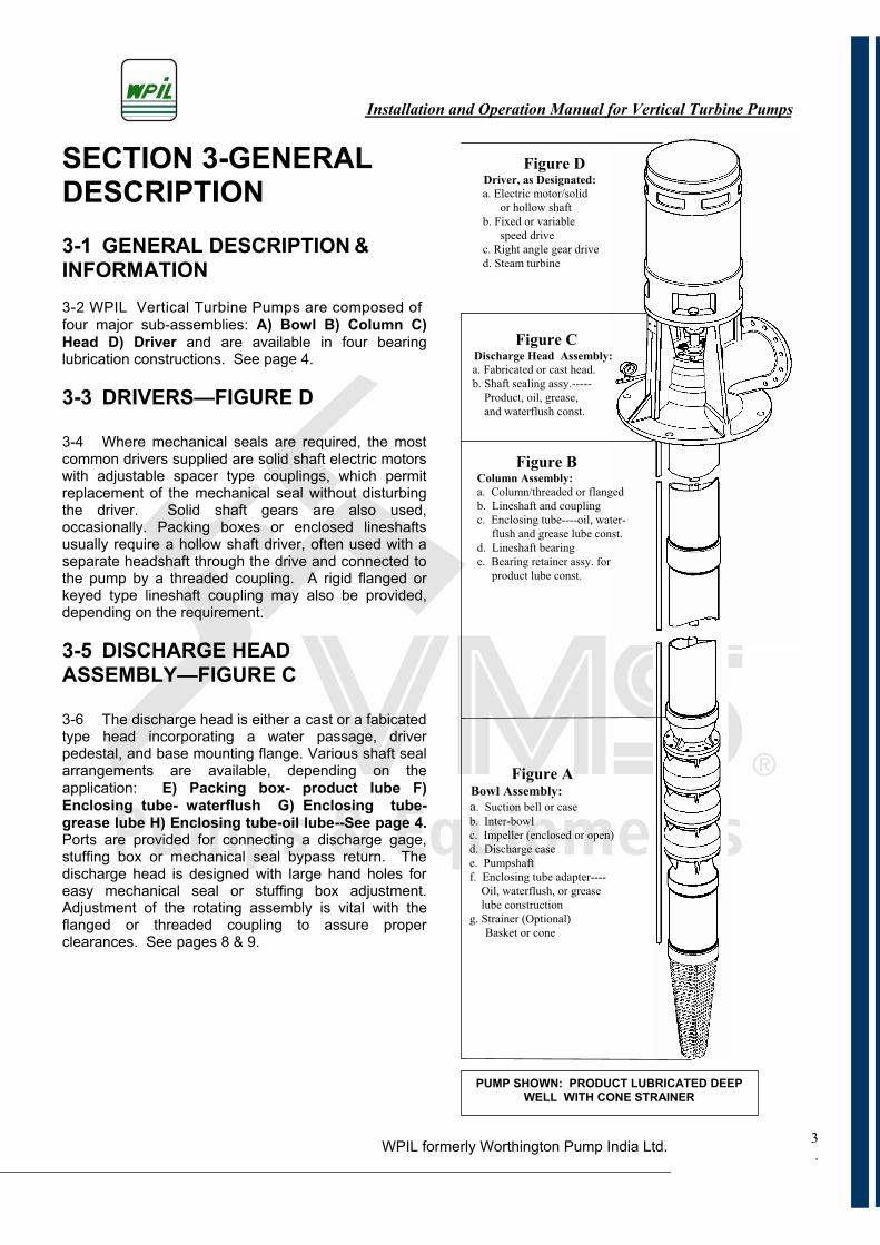
SECTION 3-GENERAL DESCRIPTION3-1 GENERAL DESCRIPTION &INFORMATION3-2 WPIL Vertical Turbine Pumps are composed of four major sub-assemblies: A) Bowl B) Column C) Head D) Driver and are available in four bearing lubrication constructions. See page 4.
3-3 DRIVERS—FIGURE D
3-4 Where mechanical seals are required, the most common drivers supplied are solid shaft electric motors with adjustable spacer type couplings, which permit replacement of the mechanical seal without disturbing the driver. Solid shaft gears are also used, occasionally. Packing boxes or enclosed lineshafts usually require a hollow shaft driver, often used with a separate headshaft through the drive and connected to the pump by a threaded coupling. A rigid flanged or keyed type lineshaft coupling may also be provided, depending on the requirement.
3-5 DISCHARGE HEAD ASSEMBLY—FIGURE C
3-6 The discharge head is either a cast or a fabicated type head incorporating a water passage, driver pedestal, and base mounting flange. Various shaft seal arrangements are available, depending on the application: E) Packing box- product lube F) Enclosing tube- waterflush G) Enclosing tube- grease lube H) Enclosing tube-oil lube--See page 4.Ports are provided for connecting a discharge gage, stuffing box or mechanical seal bypass return. The discharge head is designed with large hand holes for easy mechanical seal or stuffing box adjustment. Adjustment of the rotating assembly is vital with the flanged or threaded coupling to assure proper clearances. See pages 8 & 9.
Figure D Driver, as Designated:
a. Electric motor/solid
or hollow shaft
b. Fixed or variable
speed drive
c. Right angle gear drive
d. Steam turbine
Figure C Discharge Head Assembly:
a. Fabricated or cast head.
b. Shaft sealing assy.-----
Product, oil, grease,
and waterflush const.
Figure B Column Assembly:
a. Column/threaded or flanged
b. Lineshaft and coupling
c. Enclosing tube----oil, water-
flush and grease lube const.
d. Lineshaft bearing
e. Bearing retainer assy. for
product lube const.
Figure A Bowl Assembly:
a. Suction bell or case
b. Inter-bowl
c. Impeller (enclosed or open)
d. Discharge case
e. Pumpshaft
f. Enclosing tube adapter----
Oil, waterflush, or grease
lube construction
g. Strainer (Optional)
Basket or cone
PUMP SHOWN: PRODUCT LUBRICATED DEEP WELL WITH CONE STRAINER
Installation and Operation Manual for Vertical Turbine Pumps
WPIL formerly Worthington Pump India Ltd..
4
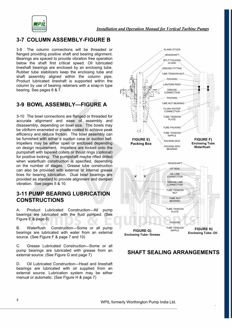
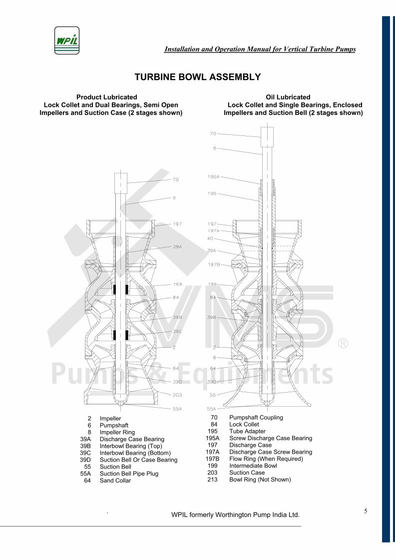
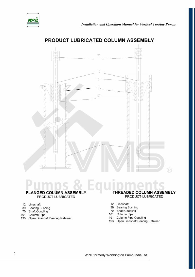
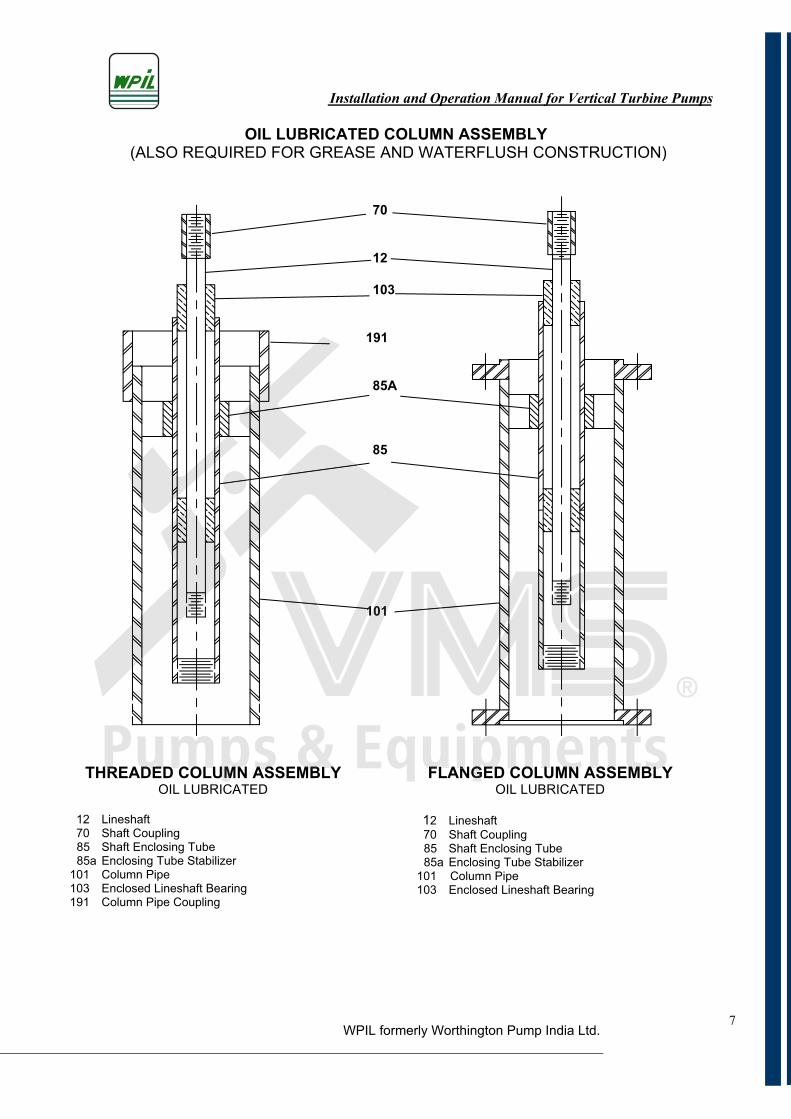
3-7 COLUMN ASSEMBLY-FIGURE B 3-8 The column connections will be threaded or flanged providing positive shaft and bearing alignment. Bearings are spaced to provide vibration free operation below the shaft first critical speed. Oil lubricated lineshaft bearings are enclosed by an enclosing tube. Rubber tube stabilizers keep the enclosing tube and shaft assembly aligned within the column pipe. Product lubricated lineshaft is supported within the column by use of bearing retainers with a snap-in type bearing. See pages 6 & 7.
3-9 BOWL ASSEMBLY—FIGURE A
3-10 The bowl connections are flanged or threaded for accurate alignment and ease of assembly and disassembly, depending on bowl size. The bowls may be vitriform enameled or plasite coated to achieve peak efficiency and reduce friction. The bowl assembly can be furnished with either a suction case or suction bell. Impellers may be either open or enclosed depending on design requirement. Impellers are locked onto the pumpshaft with tapered collets or thrust rings (optional) for positive locking. The pumpshaft maybe rifled drilled when waterflush construction is specified, depending on the number of stages. Grease lube construction can also be provided with external or internal grease lines for bearing lubrication. Dual bowl bearings are provided as standard to provide alignment and dampen vibration. See pages 5 & 10.
3-11 PUMP BEARING LUBRICATION CONSTRUCTIONSA. Product Lubricated Construction---All pump bearings are lubricated with the fluid pumped. (See Figure E & page 6)
B. Waterflush Construction---Some or all pump bearings are lubricated with water from an external source. (See Figure F & page 7 and 10)
C. Grease Lubricated Construction---Some or all pump bearings are lubricated with grease from an external source. (See Figure G and page 7)
D. Oil Lubricated Construction---Head and lineshaft bearings are lubricated with oil supplied from an external source. Lubrication system may be either manual or automatic. (See Figure H & page 7)
GLAND STUDS
HEADSHAFT
SPLIT PACKING GLAND
GREASE FITTING
TTUBE TENSION NUT
PACKING
LANTERN RING
GREASE CONNECTION
PACKING
TTUBE NUT BEARING
FLUSH WATER CONNECTION
TUBE TENSION PLATE
TUBE PACKING
TUBE TENSION NIPPLE
PACKING BOX
PACKING BOX BEARING
HEADSHAFT
LIP SEAL
OIL LINE CONNECTION
GREASE LINE CONNECTION
TUBE TENSION NUT
TUBE NUT BEARING
TUBE TENSION PLATE
PACKING
TUBE TENSION NIPPLE
FIGURE E) Packing Box
FIGURE F) Enclosing Tube
Waterflush
FIGURE G) Enclosing Tube- Grease
FIGURE H) Enclosing Tube- Oil
SHAFT SEALING ARRANGEMENTS
Installation and Operation Manual for Vertical Turbine Pumps
WPIL formerly Worthington Pump India Ltd.. 5
TURBINE BOWL ASSEMBLY
detacirbuL liO detacirbuL tcudorP Lock Collet and Dual Bearings, Semi Open
Impellers and Suction Case (2 stages shown) Lock Collet and Single Bearings, Enclosed
Impellers and Suction Bell (2 stages shown)
2 Impeller 6 Pumpshaft 8 Impeller Ring 39A Discharge Case Bearing 39B Interbowl Bearing (Top) 39C Interbowl Bearing (Bottom) 39D Suction Bell Or Case Bearing 55 Suction Bell 55A Suction Bell Pipe Plug 64 Sand Collar
70 Pumpshaft Coupling 84 Lock Collet 195 Tube Adapter 195A Screw Discharge Case Bearing 197 Discharge Case 197A Discharge Case Screw Bearing 197B Flow Ring (When Required) 199 Intermediate Bowl 203 Suction Case 213 Bowl Ring (Not Shown)
Installation and Operation Manual for Vertical Turbine Pumps
WPIL formerly Worthington Pump India Ltd.6
PRODUCT LUBRICATED COLUMN ASSEMBLY
THREADED COLUMN ASSEMBLY PRODUCT-LUBRICATED
12 Lineshaft 39 Bearing Bushing 70 Shaft Coupling 101 Column Pipe 191 Column Pipe Coupling 193 Open Lineshaft Bearing Retainer
FLANGED COLUMN ASSEMBLY PRODUCT-LUBRICATED
12 Lineshaft 39 Bearing Bushing 70 Shaft Coupling 101 Column Pipe 193 Open Lineshaft Bearing Retainer
7
OIL LUBRICATED COLUMN ASSEMBLY (ALSO REQUIRED FOR GREASE AND WATERFLUSH CONSTRUCTION)
70
12
103
191
85A
85
101
THREADED COLUMN ASSEMBLY OIL LUBRICATED
12 Lineshaft 70 Shaft Coupling
85 Shaft Enclosing Tube 85a Enclosing Tube Stabilizer
101 Column Pipe 103 Enclosed Lineshaft Bearing 191 Column Pipe Coupling
FLANGED COLUMN ASSEMBLY OIL LUBRICATED
12 Lineshaft 70 Shaft Coupling
85 Shaft Enclosing Tube 85a Enclosing Tube Stabilizer
101 Column Pipe 103 Enclosed Lineshaft Bearing
HR DEDD COLUUMN AS MBLY FLAANGED COLUMN ASS MBLY
1011
Installation and Operation Manual for Vertical Turbine Pumps
WPIL formerly Worthington Pump India Ltd.
Installation and Operation Manual for Vertical Turbine Pumps
WPIL formerly Worthington Pump India Ltd.8
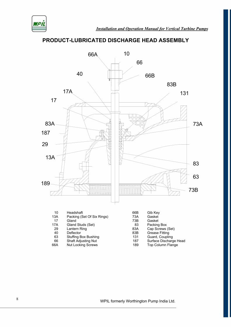
PRODUCT-LUBRICATED DISCHARGE HEAD ASSEMBLY
66A
17A
83A
13A
189
1066
66B83B
131
73A
83
63
73B
187
29
17
40
66B Gib Key 73A Gasket 73B Gasket 83 Packing Box 83A Cap Screws (Set) 83B Grease Fitting
131 Guard, Coupling 187 Surface Discharge Head
189 Top Column Flange
10 Headshaft 13A Packing (Set Of Six Rings)
17 Gland 17A Gland Studs (Set) 29 Lantern Ring
40 Deflector 63 Stuffing Box Bushing 66 Shaft Adjusting Nut 66A Nut Locking Screws
Installation and Operation Manual for Vertical Turbine Pumps
WPIL formerly Worthington Pump India Ltd.9
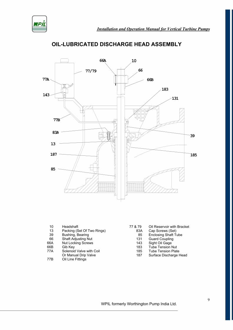
OIL-LUBRICATED DISCHARGE HEAD ASSEMBLY
66B66
66A77/79
77B
183131
39
185
85
18713
83A
143
77A
10
10 Headshaft 13 Packing (Set Of Two Rings) 39 Bushing, Bearing 66 Shaft Adjusting Nut 66A Nut Locking Screws 66B Gib Key 77A Solenoid Valve with Coil Or Manual Drip Valve 77B Oil Line Fittings
77 & 79 Oil Reservoir with Bracket 83A Cap Screws (Set) 85 Enclosing Shaft Tube 131 Guard Coupling 143 Sight Oil Gage 183 Tube Tension Nut 185 Tube Tension Plate 187 Surface Discharge Head
Installation and Operation Manual for Vertical Turbine Pumps
WPIL formerly Worthington Pump India Ltd.10
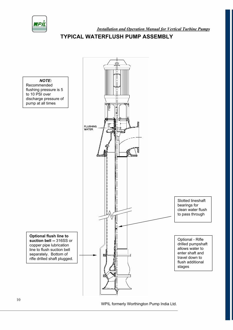
TYPICAL WATERFLUSH PUMP ASSEMBLY
Slotted lineshaft bearings for clean water flush to pass through
NOTE:Recommendedflushing pressure is 5 to 10 PSI over discharge pressure of pump at all times
Optional - Rifle drilled pumpshaft allows water to enter shaft and travel down to flush additional stages
Optional flush line to suction bell -- 316SS or copper pipe lubrication line to flush suction bell separately. Bottom of rifle drilled shaft plugged.
WPIL formerly Worthington Pump India Ltd.11
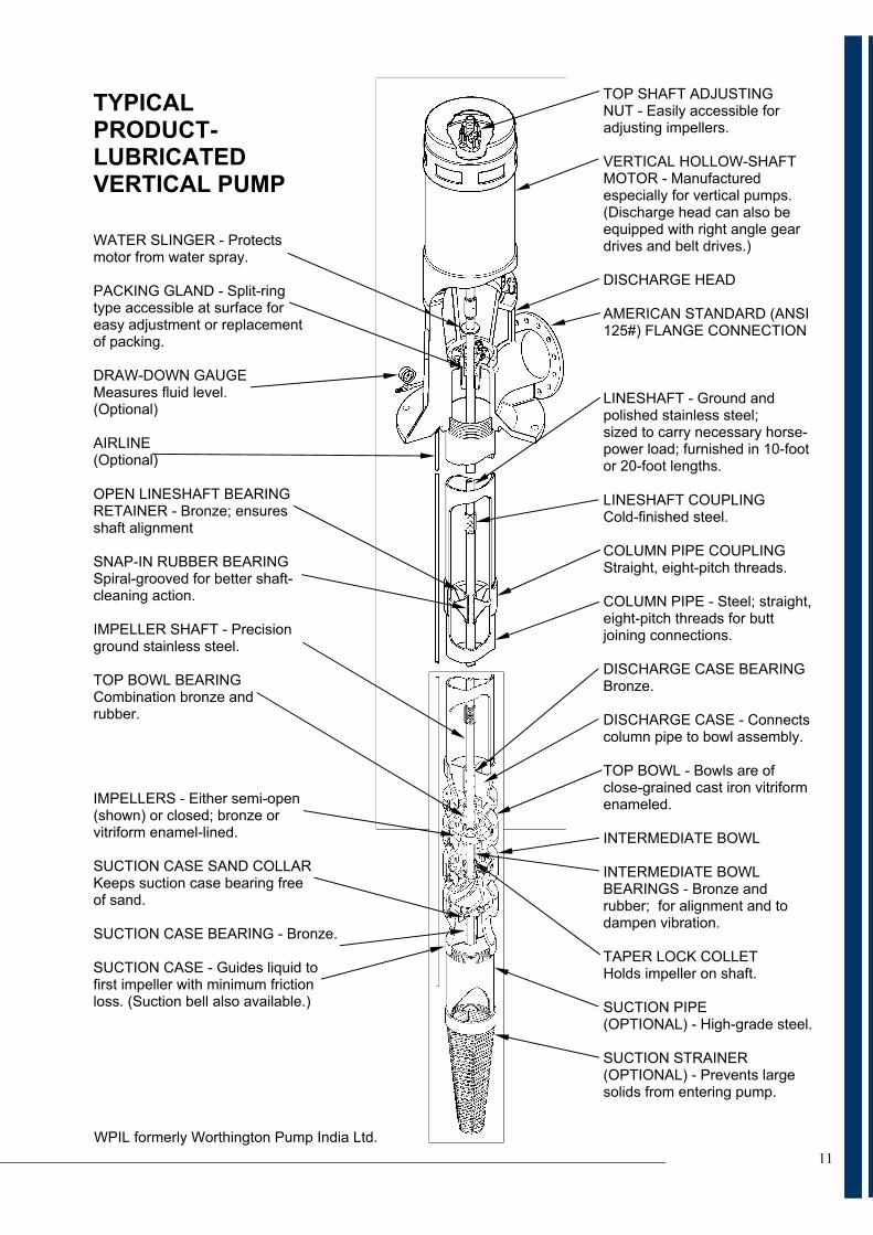
TYPICALPRODUCT-LUBRICATEDVERTICAL PUMP
WATER SLINGER - Protects motor from water spray.
PACKING GLAND - Split-ring type accessible at surface for easy adjustment or replacement of packing.
DRAW-DOWN GAUGE Measures fluid level. (Optional)
AIRLINE(Optional)
OPEN LINESHAFT BEARING RETAINER - Bronze; ensures shaft alignment
SNAP-IN RUBBER BEARING Spiral-grooved for better shaft- cleaning action.
IMPELLER SHAFT - Precision ground stainless steel.
TOP BOWL BEARING Combination bronze and rubber.
IMPELLERS - Either semi-open (shown) or closed; bronze or vitriform enamel-lined.
SUCTION CASE SAND COLLAR Keeps suction case bearing free of sand.
SUCTION CASE BEARING - Bronze.
SUCTION CASE - Guides liquid to first impeller with minimum friction loss. (Suction bell also available.)
TOP SHAFT ADJUSTING NUT - Easily accessible for adjusting impellers.
VERTICAL HOLLOW-SHAFT MOTOR - Manufactured especially for vertical pumps. (Discharge head can also be equipped with right angle gear drives and belt drives.)
DISCHARGE HEAD
AMERICAN STANDARD (ANSI 125#) FLANGE CONNECTION
LINESHAFT - Ground and polished stainless steel; sized to carry necessary horse- power load; furnished in 10-foot or 20-foot lengths.
LINESHAFT COUPLING Cold-finished steel.
COLUMN PIPE COUPLING Straight, eight-pitch threads.
COLUMN PIPE - Steel; straight, eight-pitch threads for butt joining connections.
DISCHARGE CASE BEARING Bronze.
DISCHARGE CASE - Connects column pipe to bowl assembly.
TOP BOWL - Bowls are of close-grained cast iron vitriform enameled.
INTERMEDIATE BOWL
INTERMEDIATE BOWL BEARINGS - Bronze and rubber; for alignment and to dampen vibration.
TAPER LOCK COLLET Holds impeller on shaft.
SUCTION PIPE (OPTIONAL) - High-grade steel.
SUCTION STRAINER (OPTIONAL) - Prevents large solids from entering pump.
Installation and Operation Manual for Vertical Turbine Pumps
WPIL formerly Worthington Pump India Ltd.
12
SECTION 4- FOUNDATION
4-1 PREPARING THE FOUNDATION 4-2 A foundation is required for a WPIL Vertical Turbine Pump. The foundation must be built to support the weight of the entire pump when the pump is full of water and should be rigid enough to withstand and prevent vibration.
4-3 WPIL Pumps recommends that a concrete foundation be used whenever possible. This type of foundation provides the best support and minimizes vibration.
4-4 Steel I-beams or timbers may also be used as a foundation, but they must be strong enough to prevent spring action and braced to stop lateral movement.
4-5 INSTALLATION
4-6 Sub-base(1) WPIL Pumps recommends that 2 to 3 inches of epoxy grout be required under the pump baseplate flanges to reach the desired compressive strength. Thinner pours do not generate enough exothermic reaction heat to fully cure the epoxy. NOTE: Before leveling, the sub-base or baseplate should be high enough in grout thickness as noted above.
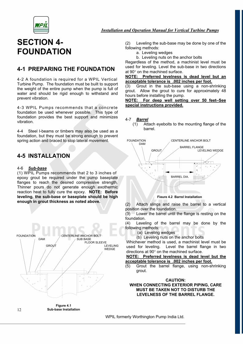
(2) Leveling the sub-base may be done by one of the following methods: a. Leveling wedges b. Leveling nuts on the anchor bolts Regardless of the method, a machinist level must be used for leveling. Level the sub-base in two directions at 90 on the machined surface. NOTE: Preferred levelness is dead level but an acceptable tolerance is .002 inches per foot.(3) Grout in the sub-base using a non-shrinking grout. Allow the grout to cure for approximately 48 hours before installing the pump. NOTE: For deep well setting over 50 feet–See special instructions provided.
4-7 Barrel(1) Attach eyebolts to the mounting flange of the
barrel.
(2) Attach slings and raise the barrel to a vertical position over the foundation. (3) Lower the barrel until the flange is resting on the foundation.(4) Leveling of the barrel may be done by the following methods: (a) Leveling wedges (b) Leveling nuts on the anchor bolts Whichever method is used, a machinist level must be used for leveling. Level the barrel flange in two directions at 90 on the machined surface. NOTE: Preferred levelness is dead level but the acceptable tolerance is .002 inches per foot.(5) Grout the barrel flange, using non-shrinking
grout.
CAUTION:WHEN CONNECTING EXTERIOR PIPING, CARE
MUST BE TAKEN NOT TO DISTURB THE LEVELNESS OF THE BARREL FLANGE.
FOUNDATION CENTERLINE ANCHOR BOLT DAM SUB BASE
FLOOR SLEEVEGROUT LEVELING
WEDGE
FOUNDATION CENTERLINE ANCHOR BOLT DAM BARREL FLANGE GROUT LEVELING WEDGE
BARREL DIA.
Figure 4.1Sub-base Installation
Figure 4.2 Barrel Installation
Installation and Operation Manual for Vertical Turbine Pumps
WPIL formerly Worthington Pump India Ltd.
13
SECTION 5- PUMP INSTALLATION
5-1 NECESSARY STEPS PRIOR TO PUMP INSTALLATION
5-2 Well Examination Examine the well before installing the pump. The well should be straight and of sufficient diameter, depth, and capacity to receive the pump. The well must be developed, tested, and free of all foreign material in the liquid before the new pump is installed. Never use a new pump to develop and test a well; use a test pump for this purpose. Your new vertical pump is not warranted for pumping foreign material in the liquid (see Section 14-4 (7) CAUTION).
5-3 Layout of Pump Parts for Inspection Uncrate and layout all parts on suitable timbers. Arrange the components in a manner that is convenient for the site and for the equipment to be used during the installation. Keep all parts away from the dirt. Be sure all the parts are clean and the threads are protected at all times. The headshaft and tube tension nipple should be left in the shipping crate until you are ready to install them.
CAUTION:Never drop any crate or part to the ground. Always use skids. Great care should be taken in handling the shafting. Do not install a bent or sprung shaft.
(1) Compare the parts against the quantities listed on the bill of material. (2) Prior to the installation of components received assembled, all nuts and bolts must be checked for tightness since they may have loosened during transportation. (3) Cleanse the lineshaft of all grease, oil and foreign matter. (4) The enclosing tube and lineshaft are ordinarily shipped assembled, if not, the shaft should be slipped into the tube carefully so no damage will occur to the shaft bearing which will serve as a coupling for the five foot lengths of tube. (5) Slide each shaft and tube section or each shaft into a matching length of column pipe. If threaded column is provided, the top end is located where the coupling is. For flanged column, either end may serve as the top end.
(6) Clean all threads, shaft ends, couplings, and mating surfaces with a solvent and wire brush just before making connections. (7) Pipe joint compound should be used on column threads. Non metallic antisieze compound should be used on the tube-connector threads and shaft threads.
5-4 INSTALLING A PARTIALLY ASSEMBLED PUMP 5-5 InstallationPumps 20 feet or less in length are usually shipped assembled, with the exception of the driver, packing, mechanical seal with tubing and coupling assembly, spacer or non-spacer type.(1) See section 14-1, Pre-start procedure before commencing the installation. (2) Check all nuts and bolts for tightness. (3) Check the mounting flange of the pump and the matching flange on the foundation for burrs and nicks. These must be smoothed with a mill file. (4) Attach a lifting device to the upper end of the assembled pump and raise it to a vertical position over the mounting foundation.
CAUTION:When a strainer is attached to the suction end of
the pump, use care not to damage the strainer when raising the assembly to the vertical position. Do not allow the suction end to drag or support the
total weight of the assembled pump. (5) Lower the unit until the mounting flange of the pump rests on the foundation.
CAUTION:When the pump is fitted with external lines such as grease, by-pass, flush etc., extreme care must be used not to damage these lines while raising or
lowering the assembly. (6) When the headshaft is shipped separately, clean the threads and install the headshaft. Hand tighten only. Note: The threads are left hand.(7) Install the shaft sealing assembly, when shipped separately, in accordance with section 9 & 10. (8) Mount the drive and align the pump in accordance with section 11 & 12. (9) Adjust the impellers in accordance with section 11.
CAUTION:When connecting piping to the pump do not put a
strain on the pump as this may cause misalignment.
Installation and Operation Manual for Vertical Turbine Pumps
WPIL formerly Worthington Pump India Ltd.14
SECTION 6-INSTALLINGTHE STRAINER ASSEMBLY
(OPTIONAL)
6-1 BASKET & CONE STRAINERS 6-2 There is a number of methods for installing strainers, but the following steps are among the most common and practical.
6-3 Cone Strainer(1) Clean the threads on the cone strainer and the suction case of the bowl assembly. (2) Apply pipe joint compound to the threads. (3) Thread the cone strainer into the suction case and tighten with chain tongs.
6-4 Cone Strainer with Suction Pipe(1) Repeat the above two steps. (2) Attach the elevators and raise the suction pipe with the strainer to a vertical position over the foundation and lower until the elevators are resting on the foundation. (3) Clean the threads on the suction pipe and the suction case of the bowl assembly. (4) Apply pipe joint compound to the threads. (5) Thread the suction pipe into the suction case.
NOTE: Suction pipe has tapered threads
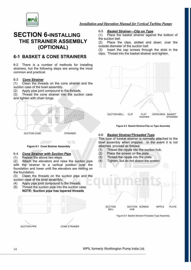
6-5 Basket Strainer—Clip on Type(1) Place the basket strainer against the bottom of the suction bell. (2) Place the clips, slotted end down, over the outside diameter of the suction bell. (3) Insert the cap screws through the slots in the clips. Thread into the basket strainer and tighten.
6-6 Basket Strainer/Threaded TypeThis type of basket strainer is normally attached to the bowl assembly when shipped. In the event it is not attached, proceed as follows: (1) Thread the nipple into the suction hub. (2) Place the screen on the plate. (3) Thread the nipple into the plate. (4) Tighten, but do not distort the screen.
SUCTION CASE STRAINER
Figure 6.1 Cone Strainer Assembly
SUCTION PIPE CONE STRAINER
SUCTION SUCTION SCREEN NIPPLE PLATE BELL HUB
SUCTION BELL CLIP FLAT CAPSCREW BASKET WASHER STRAINER
Figure 6.4 Basket Strainer/Threaded Type Assembly
Figure 6.3 Basket Strainer/Clip on Type Assembly
Installation and Operation Manual for Vertical Turbine Pumps
WPIL formerly Worthington Pump India Ltd.*Repeat Procedure15
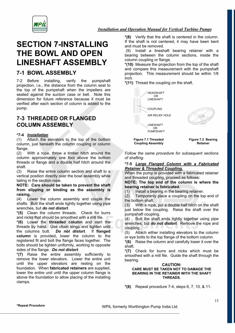
SECTION 7-INSTALLING THE BOWL AND OPEN LINESHAFT ASSEMBLY 7-1 BOWL ASSEMBLY 7-2 Before installing, verify the pumpshaft projection, i.e., the distance from the column seat to the top of the pumpshaft when the impellers are seated against the suction case or bell. Note this dimension for future reference because it must be verified after each section of column is added to the pump.
7-3 THREADED OR FLANGED COLUMN ASSEMBLY*7-4 Installation(1) Attach the elevators to the top of the bottom column, just beneath the column coupling or column flange.(2) With a rope, throw a timber hitch around the column approximately one foot above the bottom threads or flange and a double half hitch around the shaft.(3) Raise the entire column section and shaft to a vertical position directly over the bowl assembly while tailing in the section rope.NOTE: Care should be taken to prevent the shaft from slipping or binding as the assembly is raising.(4) Lower the column assembly and couple the shafts. Butt the shaft ends tightly together using pipe wrenches, but do not distort.*(5) Clean the column threads. Check for burrs and nicks that should be smoothed with a mill file. *(6) Lower the threaded column and start the threads by hand. Use chain tongs and tighten until the columns butt. Do not distort. If flangedcolumn is provided, lower the column to the registered fit and bolt the flange faces together. The bolts should be tighten uniformly, working to opposite sides of the flange. Do not distort.*(7) Raise the entire assembly sufficiently to remove the lower elevators. Lower the entire unit until the upper elevators are resting on the foundation. When fabricated retainers are supplied, lower the entire unit until the upper column flange is above the foundation to allow placing of the installing clamps.
*(8) Verify that the shaft is centered in the column. If the shaft is not centered, it may have been bent and must be removed. (9) Install a lineshaft bearing retainer with a bearing between the column sections, inside the column coupling or flange. *(10) Measure the projection from the top of the shaft and compare this measurement with the pumpshaft projection. This measurement should be within 1/8 inch.*(11) Thread the coupling on the shaft.
Follow the same procedure for subsequent sections of shafting. *7-5 Large Flanged Column with a Fabricated Retainer & Threaded Coupling.When the pump is provided with a fabricated retainer and threaded coupling, proceed as follows:NOTE: The top end of the column is where the bearing retainer is fabricated. (1) Install a bearing in the bearing retainer. (2) Temporarily place a coupling on the top end of the bottom shaft.(3) With a rope, put a double half hitch on the shaft just below the coupling. Raise the shaft over the pumpshaft coupling. (4) Butt the shaft ends tightly together using pipe wrenches, but do not distort. Remove the rope and coupling.(5) Attach either installing elevators to the column or eye bolts to the top flange of the bottom column. *(6) Raise the column and carefully lower it over the shaft.*(7) Check for burrs and nicks which must be smoothed with a mill file. Guide the shaft through the bearing.
CAUTION:CARE MUST BE TAKEN NOT TO DAMAGE THE BEARING IN THE RETAINER WITH THE SHAFT
THREADS.
*(8) Repeat procedure 7-4, steps 6, 7, 10, & 11.
HEADSHAFT OR LINESHAFT
COUPLING
AIR RELIEF HOLE
LINESHAFT OR PUMPSHAFT
Figure 7.2 Bearing Retainer
Figure 7.1 Threaded Coupling Assembly
Installation and Operation Manual for Vertical Turbine Pumps
WPIL formerly Worthington Pump India Ltd.*Repeat Procedure16
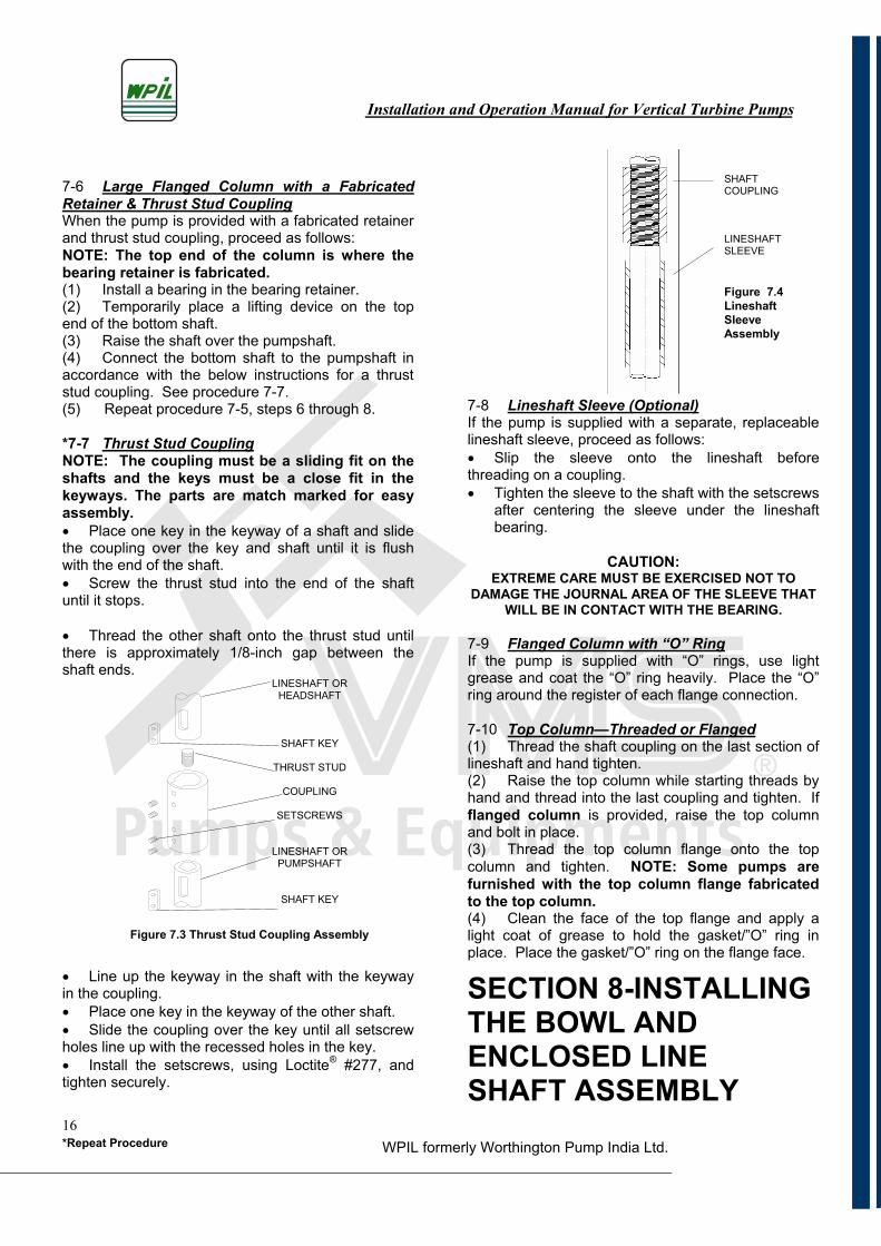
Figure 7.3 Thrust Stud Coupling Assembly
7-6 Large Flanged Column with a Fabricated Retainer & Thrust Stud CouplingWhen the pump is provided with a fabricated retainer and thrust stud coupling, proceed as follows:NOTE: The top end of the column is where the bearing retainer is fabricated. (1) Install a bearing in the bearing retainer. (2) Temporarily place a lifting device on the top end of the bottom shaft. (3) Raise the shaft over the pumpshaft. (4) Connect the bottom shaft to the pumpshaft in accordance with the below instructions for a thrust stud coupling. See procedure 7-7. (5) Repeat procedure 7-5, steps 6 through 8.
*7-7 Thrust Stud CouplingNOTE: The coupling must be a sliding fit on the shafts and the keys must be a close fit in the keyways. The parts are match marked for easy assembly. Place one key in the keyway of a shaft and slide
the coupling over the key and shaft until it is flush with the end of the shaft. Screw the thrust stud into the end of the shaft
until it stops.
Thread the other shaft onto the thrust stud until there is approximately 1/8-inch gap between the shaft ends.
Line up the keyway in the shaft with the keyway in the coupling. Place one key in the keyway of the other shaft. Slide the coupling over the key until all setscrew
holes line up with the recessed holes in the key. Install the setscrews, using Loctite® #277, and
tighten securely.
7-8 Lineshaft Sleeve (Optional)If the pump is supplied with a separate, replaceable lineshaft sleeve, proceed as follows: Slip the sleeve onto the lineshaft before
threading on a coupling. Tighten the sleeve to the shaft with the setscrews
after centering the sleeve under the lineshaft bearing.
CAUTION:EXTREME CARE MUST BE EXERCISED NOT TO
DAMAGE THE JOURNAL AREA OF THE SLEEVE THAT WILL BE IN CONTACT WITH THE BEARING.
7-9 Flanged Column with “O” Ring If the pump is supplied with “O” rings, use light grease and coat the “O” ring heavily. Place the “O” ring around the register of each flange connection.
7-10 Top Column—Threaded or Flanged(1) Thread the shaft coupling on the last section of lineshaft and hand tighten.(2) Raise the top column while starting threads by hand and thread into the last coupling and tighten. If flanged column is provided, raise the top column and bolt in place.(3) Thread the top column flange onto the top column and tighten. NOTE: Some pumps are furnished with the top column flange fabricated to the top column.(4) Clean the face of the top flange and apply a light coat of grease to hold the gasket/”O” ring in place. Place the gasket/”O” ring on the flange face.
SECTION 8-INSTALLING THE BOWL AND ENCLOSED LINE SHAFT ASSEMBLY
LINESHAFT OR HEADSHAFT
SHAFT KEY
THRUST STUD
COUPLING
SETSCREWS
LINESHAFT OR PUMPSHAFT
SHAFT KEY
SHAFTCOUPLING
LINESHAFTSLEEVE
Figure 7.4 LineshaftSleeve Assembly
Installation and Operation Manual for Vertical Turbine Pumps
WPIL formerly Worthington Pump India Ltd.*Repeat Procedure17
Figure 8.1 Enclosing Tube Assembly
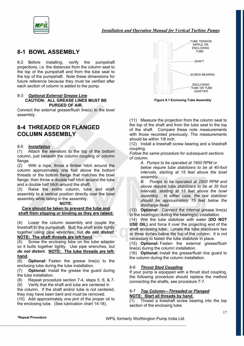
8-1 BOWL ASSEMBLY 8-2 Before installing, verify the pumpshaft projections, i.e. the distances from the column seat to the top of the pumpshaft and from the tube seat to the top of the pumpshaft. Note these dimensions for future reference because they must be verified after each section of column is added to the pump.
8-3 Optional External Grease LineCAUTION: ALL GREASE LINES MUST BE
PURGED OF AIR. Connect the external grease/flush line(s) to the bowl assembly.
8-4 THREADED OR FLANGED COLUMN ASSEMBLY
8-5 Installation(1) Attach the elevators to the top of the bottom column, just beneath the column coupling or column flange.(2) With a rope, throw a timber hitch around the column approximately one foot above the bottom threads or the bottom flange that matches the bowl flange; then throw a double half hitch around the tube and a double half hitch around the shaft. (3) Raise the entire column, tube and shaft assembly to a vertical position directly over the bowl assembly while tailing in the assembly.
NOTE:Care should be taken to prevent the tube and
shaft from slipping or binding as they are raised.
(4) Lower the column assembly and couple the lineshaft to the pumpshaft. Butt the shaft ends tightly together using pipe wrenches, but do not distort.NOTE: The shaft threads are left hand.(5) Screw the enclosing tube on the tube adapter so it butts together tightly. Use pipe wrenches, but do not distort. NOTE: The tube threads are left-hand.(6) Optional: Fasten the grease line(s) to the enclosing tube during the tube installation. (7) Optional: Install the grease line guard during the tube installation. (8) Repeat procedure section 7-4, steps 5, 6, & 7. (9) Verify that the shaft and tube are centered in the column. If the shaft and/or tube is not centered, they may have been bent and must be removed. (10) Add approximately one pint of the proper oil to the enclosing tube. (See lubrication chart 14-18).
(11) Measure the projection from the column seat to the top of the shaft and from the tube seat to the top of the shaft. Compare these note measurements with those recorded previously. The measurements should be within 1/8 inch.(12) Install a lineshaft screw bearing and a lineshaft coupling.Follow the same procedure for subsequent sections of column. A. Pumps to be operated at 1800 RPM or below require tube stabilizers to be at 40-foot intervals, starting at 15 feet above the bowl assembly. B. Pumps to be operated at 2900 RPM and above require tube stabilizers to be at 30 foot intervals, starting at 15 feet above the bowl assembly. In either case, the last stabilizer should be approximately 15 feet below the discharge head. (13) Optional: Connect the internal grease line(s) to the bearing(s) during the bearing(s) installation.(14) Wet the tube stabilizer with water (DO NOTUSE OIL) and force it over the projecting end of the shaft enclosing tube. Locate the tube stabilizers two or three inches below the top of the column. It is not necessary to fasten the tube stabilizer in place. (15) Optional: Fasten the external grease/flush line(s) during the column installation. (16) Optional: Install the grease/flush line guard to the column during the column installation.
8-6 Thrust Stud CouplingIf your pump is equipped with a thrust stud coupling, the following procedure should replace the method connecting the shafts, see procedure 7-7.
8-7 Top Column—Threaded or FlangedNOTE: Start all threads by hand.(1) Thread a lineshaft screw bearing into the top section of the enclosing tube.
TUBE TENSION NIPPLE OR ENCLOSING
TUBE
SHAFT
SCREW BEARING
ENCLOSING TUBE OR TUBE
ADAPTER
Installation and Operation Manual for Vertical Turbine Pumps
WPIL formerly Worthington Pump India Ltd.*Repeat Procedure18
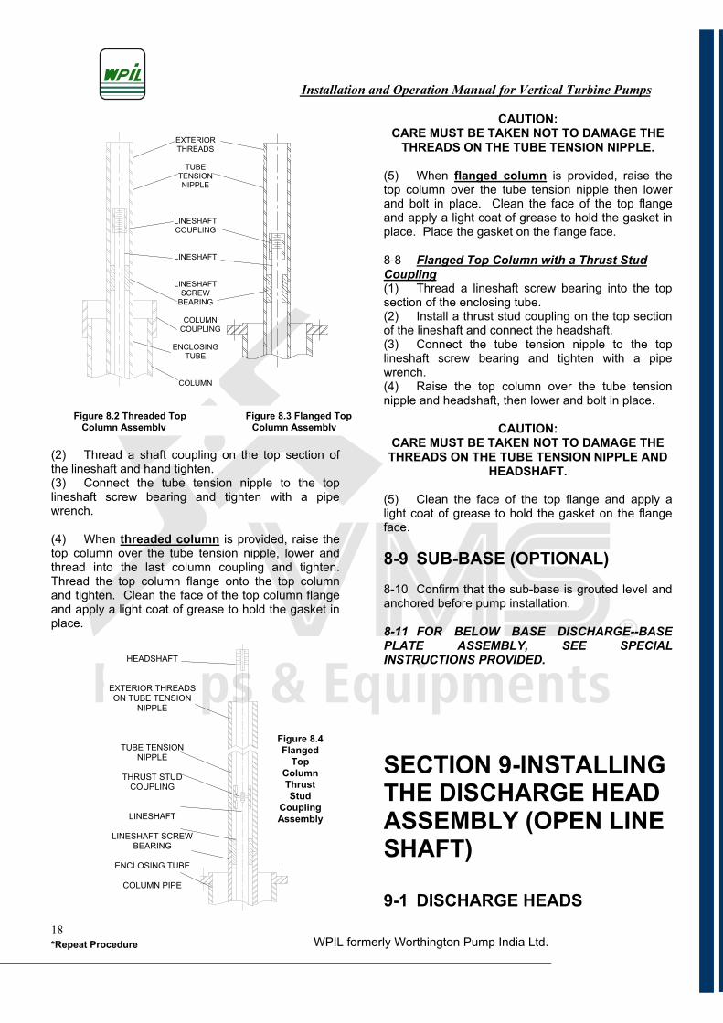
(2) Thread a shaft coupling on the top section of the lineshaft and hand tighten.(3) Connect the tube tension nipple to the top lineshaft screw bearing and tighten with a pipe wrench.
(4) When threaded column is provided, raise the top column over the tube tension nipple, lower and thread into the last column coupling and tighten. Thread the top column flange onto the top column and tighten. Clean the face of the top column flange and apply a light coat of grease to hold the gasket in place.
CAUTION:CARE MUST BE TAKEN NOT TO DAMAGE THE
THREADS ON THE TUBE TENSION NIPPLE.
(5) When flanged column is provided, raise the top column over the tube tension nipple then lower and bolt in place. Clean the face of the top flange and apply a light coat of grease to hold the gasket in place. Place the gasket on the flange face.
8-8 Flanged Top Column with a Thrust Stud Coupling(1) Thread a lineshaft screw bearing into the top section of the enclosing tube.(2) Install a thrust stud coupling on the top section of the lineshaft and connect the headshaft.(3) Connect the tube tension nipple to the top lineshaft screw bearing and tighten with a pipe wrench.(4) Raise the top column over the tube tension nipple and headshaft, then lower and bolt in place.
CAUTION:CARE MUST BE TAKEN NOT TO DAMAGE THE THREADS ON THE TUBE TENSION NIPPLE AND
HEADSHAFT.
(5) Clean the face of the top flange and apply a light coat of grease to hold the gasket on the flange face.
8-9 SUB-BASE (OPTIONAL) 8-10 Confirm that the sub-base is grouted level and anchored before pump installation.
8-11 FOR BELOW BASE DISCHARGE--BASE PLATE ASSEMBLY, SEE SPECIAL INSTRUCTIONS PROVIDED.
SECTION 9-INSTALLING THE DISCHARGE HEAD ASSEMBLY (OPEN LINE SHAFT)
9-1 DISCHARGE HEADS
HEADSHAFT
EXTERIOR THREADS ON TUBE TENSION
NIPPLE
TUBE TENSION NIPPLE
THRUST STUD COUPLING
LINESHAFT
LINESHAFT SCREW BEARING
ENCLOSING TUBE
COLUMN PIPE
Figure 8.2 Threaded Top Figure 8.3 Flanged Top Column Assembly Column Assembly
EXTERIOR THREADS
TUBETENSION NIPPLE
LINESHAFTCOUPLING
LINESHAFT
LINESHAFTSCREW
BEARING
COLUMNCOUPLING
ENCLOSINGTUBE
COLUMN
Figure 8.4Flanged
TopColumnThrustStud
CouplingAssembly
Installation and Operation Manual for Vertical Turbine Pumps
WPIL formerly Worthington Pump India Ltd.*Repeat Procedure19
9-2 Type A or type L Cast Discharge Head(1) Raise the discharge head and clean the machined area that mates with the top column flange.(2) Lower and bolt the head securely to the top column flange.(3) Raise the assembly enough to remove the elevators.(4) Remove the elevators and lower the unit until the discharge head rests on the foundation.(5) Install the headshaft through the packing box register and hand tighten only.
9-3 Type AB Cast Discharge Head(1) Thread the top column into the discharge head and tighten with chain tongs.(2) Raise the assembly, then lower and thread into the last column coupling. Tighten with chain tongs, but do not distort.(3) Raise the assembly enough to remove the lower elevators. Remove the elevators and lower the unit until the discharge head rests on the foundation.
(4) Install the headshaft through the packing box register and hand tighten only.
9-4 Large Fabricated Discharge Head(1) Raise the discharge head over the headshaft.
CAUTION:CARE MUST BE TAKEN NOT TO DAMAGE THE
THREADS ON THE HEADSHAFT. (2) Check for burrs and nicks on the top flange of the column including the register fit on the discharge head. The column flange and register fit must be smoothed with a mill file.(3) Lower the discharge head to the register fit and bolt it to the top flange of the column. The bolts must be tightened uniformly, working to opposite sides of the flange. Do not distort.(4) While raising the entire unit, remove the installing clamps and lower until the discharge head rests on the foundation. (5) Install the headshaft through the packing box register and hand tighten only.
9-5 Fabricated Barrel Discharge Head(1) Raise the head and check the flange faces for burrs and nicks that must be smoothed with a mill file.(2) Lay the barrel flange on the elevators. Lower the head and connect it to the column. (3) Raise the entire unit and remove the elevator. Place the gasket on the barrel flange.(5) Lower the entire unit and bolt the head to the barrel.
(6) Install the headshaft through the packing box register and hand tighten only.
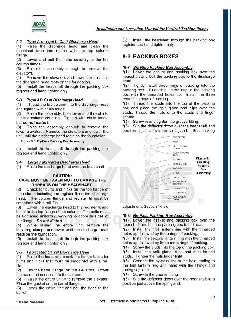
9-6 PACKING BOXES
*9-7 Six Ring Packing Box Assembly*(1) Lower the gasket and packing box over the headshaft and bolt the packing box to the discharge head.*(2) Tightly install three rings of packing into the packing box. Place the lantern ring in the packing box with the threaded holes up. Install the three remaining rings of packing.*(3) Thread the studs into the top of the packing box and place the split gland and clips over the studs. Thread the nuts onto the studs and finger tighten.*(4) Screw in and tighten the grease fitting.*(5) Slip the deflector down over the headshaft and position it just above the split gland. (See packing
adjustment, Section 14-8).
*9-8 By-Pass Packing Box Assembly*(1) Lower the gasket and packing box over the headshaft and bolt the packing box to the head.*(2) Install the first lantern ring with the threaded holes up, followed by three rings of packing. *(3) Install the second lantern ring with the threaded holes up, followed by three more rings of packing. *(4) Screw the studs into the top of the packing box. *(5) Install the split gland, clips and nuts for the studs. Tighten the nuts finger tight. *(6) Connect the by-pass line to the hole leading to the first lantern ring and head with the fittings and tubing supplied. *(7) Screw in the grease fitting. *(8) Slip the deflector down over the headshaft to a position just above the split gland.
DEFLECTOR
NUTS
SPLIT PACKING GLAND
PACKING GLAND CLIPS
PACKING
LANTERN RING
PACKING
STUDS
CAP SCREWS
PACKING BOX BEARING
GREASE FITTING
PACKING BOX
PACKING BOX GASKET
Figure 9.3 By-Pass Packing Box Assembly
Figure 9.1 Six Ring Packing
BoxAssembly
Installation and Operation Manual for Vertical Turbine Pumps
WPIL formerly Worthington Pump India Ltd.*Repeat Procedure20
SET SCREW
SHAFT SLEEVE
“O” RING
9-9 Packing Box Sleeve (Optional) Coat the “O” ring lightly with grease and install
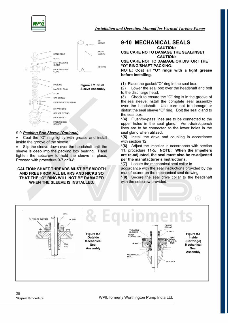
inside the groove of the sleeve. Slip the sleeve down over the headshaft until the
sleeve is deep into the packing box bearing. Hand tighten the setscrew to hold the sleeve in place. Proceed with procedure 9-7 or 9-8.
CAUTION: SHAFT THREADS MUST BE SMOOTH AND FREE FROM ALL BURRS AND NICKS SOTHAT THE “O” RING WILL NOT BE DAMAGED
WHEN THE SLEEVE IS INSTALLED.
9-10 MECHANICAL SEALS CAUTION:
USE CARE NO TO DAMAGE THE SEAL/INSET CAUTION:
USE CARE NOT TO DAMAGE OR DISTORT THE “O” RING/SHAFT PACKING. NOTE: Coat all “O” rings with a light grease before installing.
(1) Place the gasket/”O” ring in the seal box. (2) Lower the seal box over the headshaft and bolt to the discharge head. (3) Check to ensure the “O” ring is in the groove of the seal sleeve. Install the complete seal assembly over the headshaft. Use care not to damage or distort the seal sleeve “O” ring. Bolt the seal gland to the seal box. *(4) Flush/by-pass lines are to be connected to the upper holes in the seal gland. Vent-drain/quench lines are to be connected to the lower holes in the seal gland when utilized. *(5) Install the drive and coupling in accordance with section 12. *(6) Adjust the impeller in accordance with section 11, procedure 11-5. NOTE: When the impellers are re-adjusted, the seal must also be re-adjusted per the manufacturer’s instructions. *(7) Locate the mechanical seal collar in accordance with the seal instructions provided by the manufacturer on the mechanical seal drawing. *(8) Secure the seal drive collar to the headshaft with the setscrew provided. .
DEFLECTOR
NUTS
SPLIT PACKING GLAND
PACKING GLAND CLIPS
PACKING
LANTERN RING
STUD
CAP SCREW
PACKING BOX BEARING
BY-PASS LINE
GREASE FITTING
PACKING BOX
PACKING BOX GASKET
Figure 9.4 Outside
MechanicalSeal
Assembly
GLAND
SEAL
SEAL BOX
Figure 9.5 Inside
(Cartridge)Mechanical
SealAssembly
Figure 9.2 Shaft Sleeve Assembly
Installation and Operation Manual for Vertical Turbine Pumps
WPIL formerly Worthington Pump India Ltd.*Repeat Procedure21
SECTION 10-INSTALLING THE DISCHARGE HEAD ASSEMBLY(ENCLOSED LINE- SHAFT) 10-1 DISCHARGE HEADS 10-2 Type A or Type L Cast Discharge Head(1) Raise the discharge head over the tube tension nipple. Lower and bolt the head securely to the top column flange.
Caution: Be careful not to damage the tube tension nipple threads.
(2) Raise the assembly enough to remove the lower elevators.(3) Remove the elevators and lower the unit until the discharge head rests on the foundation.
10-3 Type AB Cast Discharge Head(1) Thread the top column into the discharge head and tighten with chain tongs. (2) Raise the assembly over the tube tension nipple.(3) Lower the assembly and thread it into the last section of column. Tighten with chain tongs, but donot distort.
Caution: Be careful not to damage the tube tension nipple threads.
(4) Raise the assembly enough to remove the lower elevators.(5) Remove the elevators and lower the unit until the discharge head rests on the foundation.
10-4 Large Fabricated Discharge Head(1) Raise the discharge head over the tube tension nipple.
Caution: Be careful not to damage the tube tension nipple threads.
(2) Check for burrs and nicks on the top flange of the column including the register fit on the discharge head. The column flange and register fit must be smoothed with a mill file.(3) Lower the discharge head to the register fit and then bolt to the top flange of the column. The bolts must be tightened uniformly, working to opposite sides of the flange. Do not distort.(4) Raise the entire unit while removing the installing clamps and lower until the discharge headrests on the foundation.
(5) Install the headshaft through the packing box register and hand tighten only.
10-5 TUBE TENSION NUTS
*10-6 Enclosing Tube- OilSee page 4, Figure H for the drawing illustration assembly.*(1) Install the tube tension plate using a tube tension plate wrench to tighten the plate to the tube tension nipple. NOTE: The tube tension nipplethreads are left-hand. Adjust the tube tension by stretching the tube about 1/8” for every 100 feet of tubing, or about 1-1/4 turns of the tube tension plate for every 100 feet of tubing after all slack is taken out of the tube.NOTE: FOR DEEP SETTING PUMPS (OVER 700 FEET), SEE SPECIAL INSTRUCTIONS PROVIDED.*(2) Bolt the plate to the head. *(3) Install the headshaft through the tube tension nipple and hand-tighten. NOTE: The headshaftthreads are left-hand.*(4) Install two rings of packing in the tube tension plate.(5) Check to make sure the oil passage in the tube nut is clear. Install the tube tension nut and tighten.
10-7 Enclosing Tube- GreaseSee page 4, Figure G for the drawing illustration assembly.(1) Repeat procedure 10-6, steps 1 through 4. (2) Check to make sure the grease passage in the tube tension nut is clear.(3) Install the tube tension nut and tighten. (4) Install the lip seal in the tube tension nut with the lip down.
*10-8 Enclosing Tube – Water FlushSee page 4, Figure F for the drawing illustration. (1) Repeat procedure 10-6, steps 1 through 4. *(2) Check to be sure the grease and water passages in the tube tension nut are clear. Install the tube tension nut and tighten. *(3) Install three rings of packing and place the lantern ring with the threaded holes up.*(4) Add the remaining three rings of packing and screw the studs into the top of the tube tension nut. *(5) Add the split gland, clips and nuts for the studsand tighten the nuts finger tight.*(6) Screw in the grease fitting and connect the water flush line to the fresh water supply.
Installation and Operation Manual for Vertical Turbine Pumps
WPIL formerly Worthington Pump India Ltd.*Repeat Procedure22
10-9 Enclosing Tube with Shaft Sleeve- Water Flush(1) Repeat procedure 10-6, steps 1 through 4. (2) Repeat procedure 10-8, step 2. (3) Coat the “O” ring lightly with grease and install inside the groove of the sleeve.(4) Slip the sleeve down over the headshaft until the sleeve is well into the tube tension nut bearing. Hand tighten the setscrew to hold the sleeve in place.CAUTION: SHAFT THREADS MUST BE SMOOTH
AND FREE FROM ALL BURRS AND NICKS SO THE “O” RING WILL NOT BE DAMAGED WHEN
THE SLEEVE IS INSTALLED. (5) Repeat procedure 10-8, steps 3 through 6. (6) Loosen the setscrew in the sleeve and adjust the sleeve to a position approximately one inch above the packing gland. This step will have to be made after the impeller adjustment is completed. (See Section 11, procedure 11-5 for impeller adjustment.)
SECTION 11-INSTALL- ING THE DRIVER (VHS)
11-1 HOLLOW SHAFT DRIVES
Warning: Pumps will be damaged by the wrong direction of rotation. Drive should first run UNCOUPLED from pump to check direction of rotation. Rotation of the drive should be in accordance with the rotation indicated on the nameplate.
*11-2 Electric Motor, Gear or Belt Drive*(1) Remove the drive cover and the top drive coupling. Try the drive coupling by slipping it over the headshaft. Note: This must be a sliding fit. If necessary, file, dress and polish, but do not force. Remove the coupling and try the gib key in the headshaft keyway and in the coupling keyway. This must be a sliding fit, but not loose. *(2) Raise the drive and check for burrs and nicks on the mounting register. This must be smoothed with a mill file. (3) Lower the drive over the headshaft and bolt it to the discharge head.(4) CAUTION: CARE MUST BE TAKEN NOT TO DAMAGE THE THREADS ON THE HEADSHAFT OR BEND THE HEADSHAFT.
11-3 Pump Alignment(1) Check the shaft alignment just below the pump coupling half by means of a dial indicator. The total runout at this point should not exceed .003” for 3000 RPM or faster units, or .006” for slower speed units. Preferably, the runout should be as close to .000” as possible. Care must be used when rotating the shaft so the play in the lower drive bearing does not give a false reading..
*11-4 Driver Electrical ConnectionConnect the drive terminals to the leads from the starter panel. Bump the drive to make sure the rotation is as indicated on nameplate when viewed from above. Drive should first run UNCOUPLED from pump to check direction of rotation.
If the
rotation is wrong, interchange any two leads on three phase drives. On single-phase drives, follow the manufacturer’s instructions which accompany the driver. After changing the connections, recheck the rotation.
*11-5 Impeller Adjustment*(1) Slide the top drive coupling in place and insert the gib key. The top of the key should be slightly below the top of the drive coupling. Thread the adjusting nut on the headshaft.
*(2) INITIAL ADJUSTMENT:a. Rotate the adjusting nut until the rotation assembly turns without dragging. Continue to rotate the adjusting nut until the vertical clearance obtained is slightly higher than the one listed in the pump nameplate. Install the capscrews through the adjusting nut into the coupling. b. Use an ammeter to check the preliminary setting. IMPORTANT: Make sure that the impellers are not dragging and the motor is not overloaded.
*(3) FINAL ADJUSTMENT: a. After the system is operational, the impellers can be reset to the recommended impeller lift as indicated on pump nameplate.
Installation and Operation Manual for Vertical Turbine Pumps
WPIL formerly Worthington Pump India Ltd.*Repeat Procedure23
Note: The impellers must be adjusted so that they will turn without rubbing on the top or bottom while the pump is operating.
NOTE: REFER TO THE MANUFACTURER’S SPECIAL OPERATING INSTRUCTIONS PROVIDED FOR PUMP SETTINGS 50’ OR DEEPER. MECHANICAL SEALS SHOULD BE ADJUSTED PER THE MANUFACTURER’S INSTRUCTIONS AFTER IMPELLER ADJUSTMENTS HAVE BEEN COMPLETED.
*(4) Check the lubricant in the driver in accordance with the drive lubrication instructions. *(5) The unit is now ready for operation.
11-6 HOLLOW SHAFT DRIVES WITH A TWO PIECE HEADSHAFT AND THREADED COUPLING
11-7 Electric Motor, Gear or Belt Drive
(1) Repeat procedure 11-2, steps 1 and 2. (2) Thread a shaft coupling on the lower headshaft and hand tighten. NOTE: Threads are left-hand.(3) Lower the drive and bolt it securely to the discharge head.
11-8 Driver Electrical Connection(1) Repeat procedure 11-4.
11-9 Pump Alignment(1) Install the upper headshaft through the drive hollow shaft. If the drive is supplied with a steady bushing or a guide/centering bearing, lubricate the upper headshaft with oil and use care when installing. Check the shaft alignment just below the pump coupling half by means of a dial indicator. The total runout at this point should not exceed .003” for 3000 RPM or faster units, or .006” for slower speed units. Preferably, the runout should be as close to .000” as possible. Care must be used when rotating the shaft so the play in the lower drive bearing does not give a false reading. NOTE: The shaft threads are left-hand.
11-10 Impeller Adjustment(1) Repeat all of procedure 11-5.
11-11 HOLLOW SHAFT DRIVES WITH A TWO PIECE HEADSHAFT AND RIGID FLANGED COUPLING
11-12 Electric Motor, Gear or Belt Drive Connection, Pump Alignment and Impeller Adjustment(1) Repeat procedure 11-2, steps 1 and 2.
*(2) Make sure all mating surfaces are clean and free of any burrs or chips.
NOTE: KEYS SHOULD BE A SLIP FIT IN THE HEADSHAFT KEYWAY AND THE KEYS MUST BE LUBRICATED WITH AN ANTISIEZE COMPOUND
FOR FUTURE REMOVAL. DRESS TO FIT.*(3) Slip a key and coupling half over the lower headshaft.*(4) Place a thrust ring in the thrust ring groove of the lower headshaft. *(5) Lower the drive and bolt it securely to the discharge head. *(6) Connect the electric driver as stated in procedure 11-4. *(7) Install the upper headshaft through the drive hollow shaft. If the drive is supplied with a steady bushing or a guide/centering bearing, lubricate the upper headshaft with oil and use care when installing.*(8) Slip a key and coupling over the upper headshaft.*(9) Place a thrust ring in the thrust ring groove of the upper headshaft and place the spacer on the pump coupling half. *(10) Line up the bolt holes on the coupling halves and the spacer. Orient keyway at 180 . Bolt securely together. *(11) Slide the top drive coupling in place and insert the gib key. The top of the key should be slightly below the top of the drive coupling. Thread the adjusting nut on the headshaft. *(12) Adjust the impellers in accordance with procedure 11-5. *(13) Check the shaft alignment just below the pump coupling half by means of a dial indicator. The total runout at this point should not exceed .003” for 3000 RPM or faster units, or .006” for slower speed units. Preferably, the runout should be as close to .000” as possible. Care must be used when rotating the shaft so the play in the lower drive bearing does not give a false reading. NOTE: Removing the coupling bolts and rotating the drive coupling half relative to the spacer can result in a lower runout. *(14) Check and lubricate the drive in accordance with the drive lubrication instructions.
Installation and Operation Manual for Vertical Turbine Pumps
WPIL formerly Worthington Pump India Ltd.*Repeat Procedure24
*(15) The unit is now ready for operation.
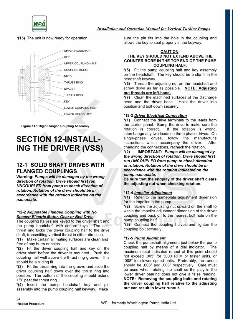
SECTION 12-INSTALL-ING THE DRIVER (VSS)
12-1 SOLID SHAFT DRIVES WITH FLANGED COUPLINGS Warning: Pumps will be damaged by the wrong direction of rotation. Drive should first run UNCOUPLED from pump to check direction of rotation. Rotation of the drive should be in accordance with the rotation indicated on the nameplate.
*12-2 Adjustable Flanged Coupling with No Spacer/ Electric Motor, Gear or Belt DriveThe coupling halves are keyed to the driver shaft and the pump headshaft with square keys. The split thrust ring locks the driver coupling half to the drive shaft, transmitting vertical thrust in either direction. *(1) Make certain all mating surfaces are clean and free of any burrs or chips. *(2) Fit the driver coupling half and key on the driver shaft before the driver is mounted. Push the coupling half well above the thrust ring groove. This should be a sliding fit. *(3) Fit the thrust ring into the groove and slide the driver coupling half down over the thrust ring into position. The bottom of the coupling should extend 1/8” past the thrust ring. *(4) Insert the pump headshaft key and pin assembly into the pump coupling half keyway. Make
sure the pin fits into the hole in the coupling and allows the key to seat properly in the keyway.
CAUTION:THE KEY SHOULD NOT EXTEND ABOVE THE
COUNTER BORE IN THE TOP END OF THE PUMP COUPLING HALF.
*(5) Fit the pump coupling half and key assembly on the headshaft. The key should be a slip fit in the headshaft keyway.*(6) Thread the adjusting nut on the headshaft and screw down as far as possible. NOTE: Adjusting nut threads are left-hand. *(7) Clean the machined surfaces of the discharge head and the driver base. Hoist the driver into position and bolt down securely.
*12-3 Driver Electrical Connection*(1) Connect the drive terminals to the leads from the starter panel. Bump the drive to make sure the rotation is correct. If the rotation is wrong, interchange any two leads on three phase drives. On single-phase drives, follow the manufactur’s instructions which accompany the driver. After changing the connections, recheck the rotation. *(2) IMPORTANT: Pumps will be damaged by the wrong direction of rotation. Drive should first run UNCOUPLED from pump to check direction of rotation. Rotation of the drive should be in accordance with the rotation indicated on the pump nameplate.Be sure that the endplay of the driver shaft clears the adjusting nut when checking rotation.
*12-4 Impeller Adjustment*(1) Refer to the nameplate adjustment dimension for the impeller in the pump.*(2) Screw the adjusting nut upward on the shaft to within the impeller adjustment dimension of the driver coupling and back off to the nearest bolt hole on the pump coupling half. *(3) Connect the coupling halves and tighten the coupling bolt securely.
*12-5 Pump AlignmentCheck the pumpshaft alignment just below the pump coupling half by means of a dial indicator. The maximum total indicated runout at this point should not exceed .005” for 3000 RPM or faster units, or .008” for slower speed units. Preferably, the runout should be .003” and .006” respectively. Care must be used when rotating the shaft so the play in the lower driver bearing does not give a false reading. NOTE: Removing the coupling bolts and rotating the driver coupling half relative to the adjusting nut can result in lower runout.
UPPER HEADSHAFT
KEY
UPPER COUPLING HALF
COUPLING BOLTS
NUTS
THRUST RING
SPACER
THRUST RING
KEY
LOWER COUPLING HALF
LOWER HEADSHAFT
Figure 11.1 Rigid Flanged Coupling Assembly
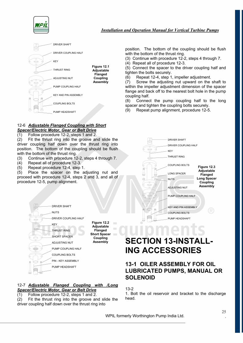
Installation and Operation Manual for Vertical Turbine Pumps
WPIL formerly Worthington Pump India Ltd. .25
12-6 Adjustable Flanged Coupling with Short Spacer/Electric Motor, Gear or Belt Drive(1) Follow procedure 12-2, steps 1 and 2. (2) Fit the thrust ring into the groove and slide the driver coupling half down over the thrust ring into position. The bottom of the coupling should be flush with the bottom of the thrust ring.(3) Continue with procedure 12-2, steps 4 through 7. (4) Repeat all of procedure 12-3. (5) Repeat procedure 12-4, step 1. (5) Place the spacer on the adjusting nut and proceed with procedure 12-4, steps 2 and 3, and all of procedure 12-5, pump alignment.
12-7 Adjustable Flanged Coupling with /Long Spacer/Electric Motor, Gear or Belt Drive(1) Follow procedure 12-2, steps 1 and 2.(2) Fit the thrust ring into the groove and slide the driver coupling half down over the thrust ring into
position. The bottom of the coupling should be flush with the bottom of the thrust ring. (3) Continue with procedure 12-2, steps 4 through 7.(4) Repeat all of procedure 12-3.(5) Connect the spacer to the driver coupling half and tighten the bolts securely. (6) Repeat 12-4, step 1, impeller adjustment.(7) Screw the adjusting nut upward on the shaft to within the impeller adjustment dimension of the spacer flange and back off to the nearest bolt hole in the pump coupling half.(8) Connect the pump coupling half to the long spacer and tighten the coupling bolts securely. (9) Repeat pump alignment, procedure 12-5.
SECTION 13-INSTALL-ING ACCESSORIES 13-1 OILER ASSEMBLY FOR OIL LUBRICATED PUMPS, MANUAL OR SOLENOID
13-21. Bolt the oil reservoir and bracket to the discharge head.
DRIVER SHAFT
NUTS
DRIVER COUPLING HALF
KEY
THRUST RING
SHORT SPACER
ADJUSTING NUT
PUMP COUPLING HALF
COUPLING BOLTS
PIN - KEY ASSEMBLY
PUMP HEADSHAFT
DRIVER SHAFT
DRIVER COUPLING HALF
KEY
THRUST RING
ADJUSTING NUT
PUMP COUPLING HALF
KEY AND PIN ASSEMBLY
COUPLING BOLTS
PUMP HEADSHAFT
DRIVER SHAFT
DRIVER COUPLING HALF
KEY
THRUST RING
COUPLING BOLTS
LONG SPACER
NUTS
ADJUSTING NUT
PUMP COUPLING HALF
KEY AND PIN ASSEMBLY
COUPLING BOLTS
PUMP HEADSHAFT
Figure 12.1 Adjustable
FlangedCouplingAssembly
Figure 12.2 Adjustable
FlangedShort Spacer
CouplingAssembly
Figure 12.3 Adjustable
FlangedLong Spacer
CouplingAssembly
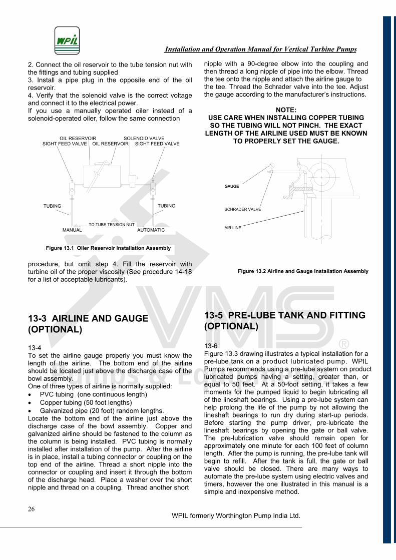
Installation and Operation Manual for Vertical Turbine Pumps
WPIL formerly Worthington Pump India Ltd.26
2. Connect the oil reservoir to the tube tension nut with the fittings and tubing supplied 3. Install a pipe plug in the opposite end of the oil reservoir.4. Verify that the solenoid valve is the correct voltage and connect it to the electrical power. If you use a manually operated oiler instead of a solenoid-operated oiler, follow the same connection
procedure, but omit step 4. Fill the reservoir with turbine oil of the proper viscosity (See procedure 14-18 for a list of acceptable lubricants).
13-3 AIRLINE AND GAUGE (OPTIONAL)
13-4To set the airline gauge properly you must know the length of the airline. The bottom end of the airline should be located just above the discharge case of the bowl assembly. One of three types of airline is normally supplied: PVC tubing (one continuous length) Copper tubing (50 foot lengths) Galvanized pipe (20 foot) random lengths.
Locate the bottom end of the airline just above the discharge case of the bowl assembly. Copper and galvanized airline should be fastened to the column as the column is being installed. PVC tubing is normally installed after installation of the pump. After the airline is in place, install a tubing connector or coupling on the top end of the airline. Thread a short nipple into the connector or coupling and insert it through the bottom of the discharge head. Place a washer over the short nipple and thread on a coupling. Thread another short
nipple with a 90-degree elbow into the coupling and then thread a long nipple of pipe into the elbow. Thread the tee onto the nipple and attach the airline gauge tothe tee. Thread the Schrader valve into the tee. Adjust the gauge according to the manufacturer’s instructions.
NOTE:USE CARE WHEN INSTALLING COPPER TUBING SO THE TUBING WILL NOT PINCH. THE EXACT
LENGTH OF THE AIRLINE USED MUST BE KNOWN TO PROPERLY SET THE GAUGE.
13-5 PRE-LUBE TANK AND FITTING (OPTIONAL)
13-6Figure 13.3 drawing illustrates a typical installation for a pre-lube tank on a product lubricated pump. WPILPumps recommends using a pre-lube system on productlubricated pumps having a setting, greater than, or equal to 50 feet. At a 50-foot setting, it takes a few moments for the pumped liquid to begin lubricating all of the lineshaft bearings. Using a pre-lube system can help prolong the life of the pump by not allowing the lineshaft bearings to run dry during start-up periods. Before starting the pump driver, pre-lubricate the lineshaft bearings by opening the gate or ball valve. The pre-lubrication valve should remain open for approximately one minute for each 100 feet of column length. After the pump is running, the pre-lube tank will begin to refill. After the tank is full, the gate or ball valve should be closed. There are many ways to automate the pre-lube system using electric valves and timers, however the one illustrated in this manual is a simple and inexpensive method.
GAUGE
SCHRADER VALVE
AIR LINE
GAUGE
OIL RESERVOIR SOLENOID VALVE SIGHT FEED VALVE OIL RESERVOIR SIGHT FEED VALVE
MANUAL AUTOMATIC
Figure 13.1 Oiler Reservoir Installation Assembly
TUBING
TO TUBE TENSION NUT
TUBING
Figure 13.2 Airline and Gauge Installation Assembly
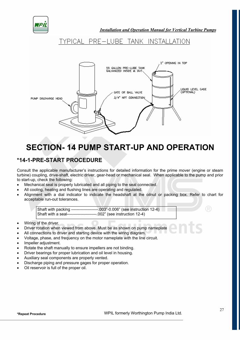
Installation and Operation Manual for Vertical Turbine Pumps
WPIL formerly Worthington Pump India Ltd.*Repeat Procedure27
SECTION- 14 PUMP START-UP AND OPERATION *14-1-PRE-START PROCEDURE Consult the applicable manufacturer’s instructions for detailed information for the prime mover (engine or steam turbine) coupling, drive-shaft, electric driver, gear-head or mechanical seal. When applicable to the pump and prior to start-up, check the following: Mechanical seal is properly lubricated and all piping to the seal connected. All cooling, heating and flushing lines are operating and regulated. Alignment with a dial indicator to indicate the headshaft at the oilnut or packing box. Refer to chart for
acceptable run-out tolerances.
Wiring of the driver. Driver rotation when viewed from above. Must be as shown on pump nameplate All connections to driver and starting device with the wiring diagram. Voltage, phase, and frequency on the motor nameplate with the line circuit. Impeller adjustment. Rotate the shaft manually to ensure impellers are not binding. Driver bearings for proper lubrication and oil level in housing. Auxiliary seal components are properly vented. Discharge piping and pressure gages for proper operation. Oil reservoir is full of the proper oil.
Shaft with packing --------------------.003”-0.006” (see instruction 12-4)Shaft with a seal----------------------.002” (see instruction 12-4)
Installation and Operation Manual for Vertical Turbine Pumps
WPIL formerly Worthington Pump India Ltd.*Repeat Procedure28
14-2 PRIMING
The first stage must always be completely submerged. The pump must not run dry as the rotating parts within the pump may gall and seize to the stationary parts. The liquid being pumped must lubricate the parts.
14-3 PUMP START-UP/PRODUCT LUBRICATED
*14-4 VHS or VSS Drive*(1) For settings greater than fifty feet, open the pre-lube valve and allow fluid to run for one minute per each 100 feet of setting to pre-lubricate the lineshaft bearings.*(2) Momentarily bump-start the driver to tighten all the lineshaft couplings then immediately stop the pump. This step is necessary only on the initial start-up after pump installation. *(3) Re-check the impeller adjustment making sure the rotating element turns freely by hand. If impeller adjustment is required, see Section 11 or Section 12 as applicable to the pump. *(4) For settings greater than fifty feet, repeat step (1) as above. *(5) Set the discharge valve to a nearly closed position before starting the pump on a new installation.*(6) Start the pump and then open the valve slowly after the liquid begins to flow.
*(7) CAUTION: THIS NEW PUMP IS NOT WARRANTED FOR PUMPING FOREIGN MATERIAL IN THE LIQUID. All foreign material should have been removed from the sump, well system, etc. before the pump was installed to avoid possible pump damage. In the event foreign material is encountered, the following instructions will minimize the damage:
Do not immediately stop the pump. If you stop it while foreign material is still present in the flow, additional foreign material suspended in the liquid may settle in the pump bowls and cause the rotating element to seize.
Stop the unit after the fluid has cleared. Determine the extent of the damage incurred in
pumping the foreign material. It may be necessary to pull the unit to check the problem.
14-5 IMPORTANT OPERATING GUIDELINES*14-6 Operating Guidelines for Vertical Turbine PumpsFollowing these helpful guidelines will assure longer life for your vertical pump. *(1) If the pump loses its prime or breaks suction, immediately shut it down! DO NOT RUN IT DRY! The impellers and bearing have small clearances and may bind and cause serious trouble. NOTE: Productlubricated rubber lineshaft bearings require continuous lubrication.*(2) It is better to operate the pump without suction lift. Ideal operating conditions call for at least ten feet of submergence for the top bowl—although this may vary, depending on the installation. For example, a small-capacity pump in a large diameter well will require less submergence than a large-capacity pump in a small-diameter well.*(3) If the pump capacity is too great for the supply, it is better to throttle the pump than to let it break suction. Only vertical turbine and mixed flow pumps may be throttled, however, the throttling should be limited to 50 percent of design flow. NOTE: Throttling may affect impeller adjustment and driver load.*(4) When the pump is stopped, the flow of liquid backing down through the column will cause the pump to rotate backward without a foot valve or a non-reverse ratchet. Caution: Never start the pumpagain while this backward rotation is occurring! If you do, you will place a severe strain on the shafting and it may break. Always allow the pump to stop completely before restarting it.*(5) The discharge head should never be the sole support for the discharge pipe. Use concrete or steel structures as the primary support.*(6) If the pump is operating in a closed system, an air-relief valve should be installed on the discharge pipe between the discharge head and the check valve. Air must be admitted to the column when the pump is stopped and vented when the pump is started.
14-7 LUBRICATION DURING OPERATION/PRODUCT LUBRI- CATED PUMPS 14-8 Stuffing BoxWhen the pump is in operation, there should be some leakage at the stuffing box packing. For cooling and lubrication, allow approximately 60 drops of liquid to escape each minute. Upon initial start-up, use a hand grease gun filled with a light waterproof grease and apply two full strokes of grease to the packing at the grease fitting. NOTE: Do not over grease, sincethis may distort the split gland. Packing lubrication is not required after initial start-up.
Installation and Operation Manual for Vertical Turbine Pumps
WPIL formerly Worthington Pump India Ltd.*Repeat Procedure29
14-9 Mechanical SealIf the seal leaks slightly at start-up, allow a reasonable amount of time for the seal to adjust itself. Liquids with good lubricating qualities normally take longer to wear in the seal than liquid with lesser qualities. When a seal starts out with a slight leak and gets progressively less with running, it indicates leakage across the seal faces and continued running will usually eliminate this. Where leakage occurs immediately and remains constant, unaffected by running, it usually indicates a secondary seal damage (shaft packing), or the seal faces are warped out of flat. See Section 19Troubleshooting, for possible causes and remedies.
*14-10 Suction BearingThe suction bearing for your new vertical pump was packed with grease at the factory and will not require further attention until the pump is removed from service. Before re-installing the pump, repack the suction bearing with any of the following greases:
*14-11 Suction Bearing Lubrication ChartLyondell . . . . . . . . . . . . . . Litholine H EP # 2Exxon . . . . . . . . . . . . . . . Lidox EP # 2Sun Oil. . . . . . . . . . . . . . . Sun Prestige EP # 2Mobil . . . . . . . . . . . . . . . . Mobilux EP # 2Phillips . . . . . . . . . . . . . . . Philube EP # 2Shell . . . . . . . . . . . . . . . . Alvania EP # 2Chevron . . . . . . . . . . . . . Duralith EP # 2Citgo. . . . . . . . . . . . . . . . Premium Lithium EP #2
USDA H-1 Lubricants: Chevron ……...Chevron FM Greases EP NLGI 2Shell…. Shell Cassida Grease EPS 2
NOTE: When pumping grease dissolving fluid or operating the pump at high temperatures, grease is not used in the suction bearing. For these types of applications, do not pack the suction with grease when re-installing the pump.
14-12 PUMP START-UP/OIL LUBRI- CATED PUMPS 14-13 VHS Drive(1) Verify that the oil reservoir is full of the proper oil.
See the lubrication chart in section 14-18. (2) Adjust the sight feed valve to one drop per second.(3) Momentarily bump-start the driver to tighten all the lineshaft couplings, then immediately stop thepump. This step is necessary only on the initial start-up after pump installation.(4) Re-check the impeller adjustment making sure the rotating element turns freely by hand. If impeller
adjustment is required, see section 11 as applicable to the pump.(5) Set the discharge valve to a nearly closed position before starting the pump on a new installation.(6) Start the pump and then open the valve slowly after the liquid begins to flow. (7) Review procedure 14-4, step 7—Caution. After the fluid pumped has cleared, adjust the sight feed valve to one drop of oil per minute for each 40 feet of column (but never under 5 drops per minute) for the first week of operation.
NOTE:MANUAL AND AUTOMATIC LUBRICATORS USE
THE SAME ADJUSTMENTS. THE MANUAL LUBRICATOR MUST BE SHUT OFF WHEN THE
PUMP IS IDLE.
14-14 ADDITIONAL IMPORTANT OPERATING GUIDELINES 14-15 Oil Lubricated Pumps(1) Review all of section 14-6—Operating Guidelines.(2) Keep the oil supply container covered. Do not permit the container to collect dirt.(3) Check the oil reservoir at least once every eight hours to assure an adequate supply of lubricant.
14-16 LUBRICATION DURING OPERATION/OIL LUBRICATED PUMPS14-17Lineshaft LubricantUsing the lubricants listed below will help ensure proper operation and long pump life. Use turbine oil only. Do not use automotive or diesel engine lubricating oils. The oils listed below are recommended for lubricating lineshaft bearings:
14-18Lineshaft Lubrication Chart-Hydrocarbon Oils Lyondell . . . . . . . . . . . . . . . . Duro 32 Exxon . . . . . . . . . . . . . . . . . . Terresstic Gulf . . . . . . . . . . . . . . . . . . . Gulfcrest # 32 Mobil . . . . . . . . . . . . . . . . . . . DTE # 797 Phillips . . . . . . . . . . . . . . . . . Magnus 150 Shell . . . . . . . . . . . . . . . . . . . Turbo # 32 Chevron . . . . . . . . . . . . . . . .GST # 32 Sun . . . . . . . . . . . . . . . . . . . Sunvis # 916 Texaco . . . . . . . . . . . . . . . . Regal 32 (R&O) Citgo . . . . . . . . . . . . . . . . . . PaceMaker 32
NSF Approved Food Grade Oils Citgo . . . . . . . . . . . . . . . . . . Ideal GF #32 Chevron . . . . . . . . . . . . . . . FM #32 Texaco . . . . . . . . . . . . . . . . Cynus #32 Huskey . . . . . . . . . . . . . . . . 15A14
Installation and Operation Manual for Vertical Turbine Pumps
WPIL formerly Worthington Pump India Ltd.*Repeat Procedure30
14-19 Suction Bearing Lubricant(1) Review all of procedure 14-10 & 14-11.
14-20 PUMP START-UP & LUBRICATION DURING OPERA- TION/GREASE LUBRICATED
14-21 VHS DriveCAUTION: THE GREASE LINES MUST HAVE BEEN
PURGED OF AIR BEFORE PROCEEDING. (1) Fill the grease reservoir and fill all the grease lines. For proper grease selection see the lubrication chart in section 14-23.(2) A heavy duty, high-pressure grease gun is recommended for manual operation. When using an automatic grease system see the manufacturer’s instructions for operation.(3) Repeat procedure 14-4, steps 2 through 6. Pump Start-Up(4) Review procedure 14-4, step 7—Caution.NOTE: The bearings must be lubricated every eight hours of operation. (5) Review all of procedure 14-6. Operating Guidelines.14-22 Lineshaft LubricantThe greases listed below are recommended for automatic lubricator applications and for grease packing the shaft enclosing tube for grease lubricated lineshaft bearings. 14-23 Grease Lubrication Chart
14-24Suction Bearing Lubricant(1) Review all of procedure 14-10 & 14-11.
14-25 PUMP START-UP &LUBRICATION DURING OPERA- TION/WATERFLUSH LUBRICATED
14-26 VHS Drive(1) Tighten the packing gland nuts finger tight.(2) Flush the pump bearings with 1-5 GPM of water at a pressure of 15 PSI greater than the discharge pressure of the pump. NOTE: Establish the flow rate BEFORE the pump is started.(3) Control the packing gland leakage after start-up by tightening or loosening the gland nuts. Always allow enough leakage to keep the tube tension nut cool.NOTE: When the pump is in operation, there should be some leakage at the stuffing box packing. For cooling and lubrication, allow approximately 60 drops of liquid to escape each minute. Upon initial start-up,use a hand grease gun filled with a light waterproof grease and apply two full strokes of grease to the packing at the grease fitting.(4) Repeat procedure 14-4, steps 2 through 6. Pump Start-Up.(5) Review procedure 14-4, step 7—Caution.(6) Review procedure 14-6. Operating Guidelines.
14-27 Suction Bearing Lubricant(1) Review procedure 14-10 & 14-11.
14-28 RECOMMENDED SPARE PARTS14-29 Recommended Spare Parts for Product, Oil, Grease and Waterflush Construction.
(1) Procedure for ordering spare parts: List the serial number of the pump List the part number (from the bill of material) List the quantity List the complete part description (from the bill of
material)
(2) List of parts subject to the most wear: Bowl assembly/lineshaft bearings Shaft sealing assembly bearing Seal rings/wear rings/liners Packing Complete mechanical seal (less gland and sleeve)
(3) List of parts to be stocked if down time is critical: Gaskets and “o” rings Rotating parts Seal rings/wear rings/liners Driver bearings and mechanical seal sleeve
Company Normal Temp. Low Temp.
Lyondell Litholine H EP #1 Litholine H EP #00 Exxon Lidox EP #1 Lidok EP #0 Citgo Premium Lithium
EP #1 Premium Lithium EP #0
Mobil Mobilux EP #1 Mobilux EP #0 Phillips Philube EP #1 ---------------------- Shell Alvania EP #1 Alvania EP R/0 Sun Sun Prestige
EP #1 Sun Prestige EP #0
Texaco Novatex #1 Low Temp. EP Chevron Duralith EP #1 Duralith EP #0
Installation and Operation Manual for Vertical Turbine Pumps
WPIL formerly Worthington Pump India Ltd.*Repeat Procedure31
SECTION 15-MAINTE- NANCE INSTRUCTIONS BOWL ASSEMBLY, LOCK COLLET CON- STRUCTION
READ THE FOLLOWING INSTRUCTIONS THOROUGHLY BEFORE DISASSEMBLING OR REASSEMBLING A BOWL ASSEMBLY.
15-1 VERTICAL TURBINE PUMP BOWL ASSEMBLY, PRODUCT LUBRICATED, ENCLOSED IMPELLER(S)
*15-2 Assembly Procedure*(1) Layout the bowl assembly parts and check them against the bill of material. *(2) Check the impeller diameter against the trim shown on the bill of material. *(3) Install the bearings in the bowls. Where dual bearings are required (check the bill of material), press the bronze bearings into place then install the rubber bearings using 3M Scotch-Grip 1711 Rubber Adhesive (or an equivalent product) to hold them in place. Do not get adhesive into any bearing bore. Install the suction bearing in the suction (on some pumps, the suction bearing will project above the suction bearing hub).NOTE: The discharge case and the top intermediate bowl must be screwed or bolted together (depending on the type of construction being used), and the combination bearing must be pressed in the intermediate bowl flush with the top of the rubber bearing pocket.(4) Position the bottom impeller at the pin line etched on the pumpshaft. *(5) Clamp the pumpshaft in a vice with a soft metal cover on the jaws. Slip an impeller and taper lock collet over the end of the pumpshaft and lock it into position using a lock collet hammer (available from WPIL Limited.). When the lock collet is in the proper position, it will project about 1/8 inch above the impeller hub. (6) Use a straightedge to verify that the bottom of the impeller wear ring is aligned with the pin line on
the pumpshaft. If adjustment is required, remove the impeller by using the opposite end of the lock collet hammer. If a sand collar is provided (see bill of material), install it on the shaft beneath the impeller. (7) Insert the pumpshaft into the suction bearing and position it so the impeller seats in the bowl wear ring seat. *(8) Support the pumpshaft with collapsible supports at several points to hold it horizontal. *(9) Remove the pipe plug from the bottom of the suction piece. (10) Thread the stop into the bottom of the shaft and tighten it firmly to seat the impeller in the bowl. Keep this stop tight while assembling the bowl. NOTE: After the bowl assembly is completed, the stop must be removed. (See step 16 below).*(11) Slip an intermediate bowl over the end of the shaft and bolt or thread the bowl in position (depending on whether flanged or threaded bowls are required). (12) Place the next impeller and lock collet on the pumpshaft and use the lock collet hammer to lock them in position in the bowl ring seat.
SEE THE ILLUSTRATIONS ON PAGES 35 & 36 FOR
ASSEMBLY AND DISASSEMBLY OF A LOCK
COLLET IMPELLER(S)
*(13) Compare the endplay with the specification on the bill of material. Do this by unthreading the pumpshaft stop and measuring the lateral travel of the shaft; this travel is the endplay. Relock the shaft and proceed to install the bowls and impellers for the remaining number of stages. *(14) After the final impeller is positioned, install the top inter-bowl and the discharge case. Bolt or thread the assembly in position (depending on whether threaded or flanged construction is provided). Recheck the endplay. *(15) With the impellers in their lowest position, verify that the pumpshaft projection matches what’s specified on the bill of material. The projection is the distance from the end of the shaft to the column seat when the shaft is in its lowest position. NOTE: The column seat for threaded column is the point at which the column bottoms. The column seat for flanged column is the face of the flange. *(16) Remove the stop from the bottom of the shaft.
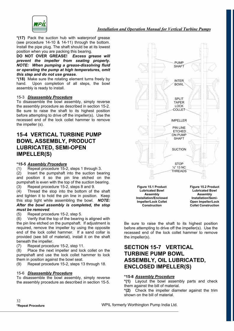
Installation and Operation Manual for Vertical Turbine Pumps
WPIL formerly Worthington Pump India Ltd.*Repeat Procedure32
*(17) Pack the suction hub with waterproof grease (see procedure 14-10 & 14-11) through the bottom. Install the pipe plug. The shaft should be at its lowest position when you are packing this bearing. DO NOT OVER GREASE! Excess grease will prevent the impeller from seating properly. NOTE: When pumping a grease-dissolving fluid or operating the pump at high temperatures, omit this step and do not use grease. *(18) Make sure the rotating element turns freely by hand. Upon completion of all steps, the bowl assembly is ready to install.
15-3 Disassembly ProcedureTo disassemble the bowl assembly, simply reverse the assembly procedure as described in section 15-2. Be sure to raise the shaft to its highest position before attempting to drive off the impeller(s). Use the recessed end of the lock collet hammer to remove the impeller (s).
15-4 VERTICAL TURBINE PUMP BOWL ASSEMBLY, PRODUCT LUBRICATED, SEMI-OPEN IMPELLER(S)
*15-5 Assembly Procedure(1) Repeat procedure 15-2, steps 1 through 3. (2) Insert the pumpshaft into the suction bearing and position it so the pin line etched on the pumpshaft is even with the top of the suction bearing. (3) Repeat procedure 15-2, steps 8 and 9. (4) Thread the stop into the bottom of the shaft and tighten it to hold the pin line in position. Keep this stop tight while assembling the bowl. NOTE:After the bowl assembly is completed, the stop must be removed.(5) Repeat procedure 15-2, step 5. (6) Verify that the top of the bearing is aligned with the pin line etched on the pumpshaft. If adjustment is required, remove the impeller by using the opposite end of the lock collet hammer. If a sand collar is provided (see bill of material), install it on the shaft beneath the impeller. (7) Repeat procedure 15-2, step 11. (8) Place the next impeller and lock collet on the pumpshaft and use the lock collet hammer to lock them in position against the bowl seat. (9) Repeat procedure 15-2, steps 13 through 18.
15-6 Disassembly ProcedureTo disassemble the bowl assembly, simply reverse the assembly procedure as described in section 15-5.
Be sure to raise the shaft to its highest position before attempting to drive off the impeller(s). Use the recessed end of the lock collet hammer to remove the impeller(s).
SECTION 15-7 VERTICAL TURBINE PUMP BOWL ASSEMBLY, OIL LUBRICATED,ENCLOSED IMPELLER(S) *15-8 Assembly Procedure*(1) Layout the bowl assembly parts and check them against the bill of material.*(2) Check the impeller diameter against the trim shown on the bill of material.
PUMPSHAFT
INTERBOWL
SPLITTAPERLOCK
COLLET
IMPELLER
PIN LINE ETCHED ON PUMP
SHAFT
SUCTION
STOP½” 13 NC THREADS
Figure 15.1 Product Lubricated Bowl
Assembly Installation/EnclosedImpeller/Lock Collet
Construction
Figure 15.2 Product Lubricated Bowl
Assembly Installation/Semi-
Open Impeller/Lock Collet Construction
Installation and Operation Manual for Vertical Turbine Pumps
WPIL formerly Worthington Pump India Ltd.*Repeat Procedure33
*(3) Install the bearings in the bowls. Where dual bearings are required (check the bill of material), press the bronze bearings into place then install the rubber bearings using 3M Scotch-Grip 1711 Adhesive (or an equivalent product) to hold them in place. Do not get adhesive into any bearing bore. Install the suction bearing in the suction (on some pumps, the suction bearing will project above the suction bearing hub). NOTE: The discharge case and the top intermediate bowl must be screwed or bolted together (depending on the type of construction being used), and the combination bearing must be pressed in the intermediate bowl flush with the top of the rubber bearing pocket. NOTE: Check the by-pass ports to verify that the combination bearing does not seal them shut. If these ports are closed, the tube and shaft will not be properly lubricated and early pump failure will result. CAUTION: Never install a rubber bearing in the top inter-bowl! (4) Position the bottom impeller at the pin line etched on the pumpshaft.*(5) Clamp the pumpshaft in a vice with a soft metal cover on the jaws. Slip an impeller and taper lock collet over the end of the pumpshaft and lock it into position using a lock collet hammer (available from WPIL Limited.). When the lock collet is in the proper position, it will project about 1/8 inch above the impeller hub.(6) Use a straightedge to verify that the bottom of the impeller wear ring is aligned with the pin line on the pumpshaft. If adjustment is required, remove the impeller by using the opposite end of the lock collet hammer. If a sand collar is provided (see parts list/), install it on the shaft beneath the impeller.(7) Insert the pumpshaft into the suction bearing and position it so the impeller seats in the bowl wear ring seat.*(8) Support the pumpshaft with collapsible supports at several points to hold it horizontal.*(9) Remove the pipe plug from the bottom of the suction piece.(10) Thread the stop into the bottom of the shaft and tighten it firmly to seat the impeller in the bowl. Keep this stop tight while assembling the bowl. NOTE: After the bowl assembly is completed, the stop must be removed (see step 21).*(11) Slip an intermediate bowl over the end of the shaft and bolt or thread the bowl in position (depending on whether flanged or threaded bowls are required). (12) Place the next impeller and lock collet on the pumpshaft and use the lock collet hammer to lock them in position in the bowl ring seat.
*(13) Compare the endplay with the specification on the bill of material. Do this by unthreading the pumpshaft stop and measuring the lateral travel of the shaft; this travel is the endplay. Relock the shaft and proceed to install the bowls and impellers for the remaining stages.*(14) After the final impeller is positioned, install the top inter-bowl and the discharge case. Bolt or thread the assembly in position (depending on whether threaded or flanged construction is provided).*(15) Install the O-ring slinger on the shaft in line with the bypass ports located in the discharge case. Recheck the endplay.*(16) Verify that the pumpshaft projection matches what’s specified on the bill of material. The projection is the distance from the end of the shaft to the column seat when the shaft is in its lowest position. NOTE: The column seat for threaded column is the point at which the column bottoms. The column seat for flanged column is the face of the flange.*(17) Thread the discharge case screw bearing into the discharge case.*(18) Thread the tube adapter on the discharge case screw bearing and tighten.*(19) Thread the tube adapter screw bearing into the tube adapter. *(20) With the impellers in their lowest position, check the projection of the shaft above the tube seat.*(21) Remove the stop from the bottom of the shaft.*(22) Pack the suction hub with waterproof grease (see procedure 14-10 & 14-11) through the bottom. Install the pipe plug. The shaft should be at its lowest position when you are packing this bearing,. DO NOT OVER GREASE! Excess grease will prevent the impeller from seating properly. NOTE: When pumping a grease-dissolving fluid or operating the pump at high temperatures, omit this step and do not use grease. *(23) Make sure the rotating element turns freely by hand. Upon completion of all steps, the bowl assembly is ready to install.
15-9 Disassembly ProcedureTo disassemble the bowl assembly, simply reverse the assembly procedure as described in section 15-8. Be sure to raise the shaft to its highest position before attempting to drive off the impeller(s). Use the recessed end of the lock collet hammer to remove the impeller(s).
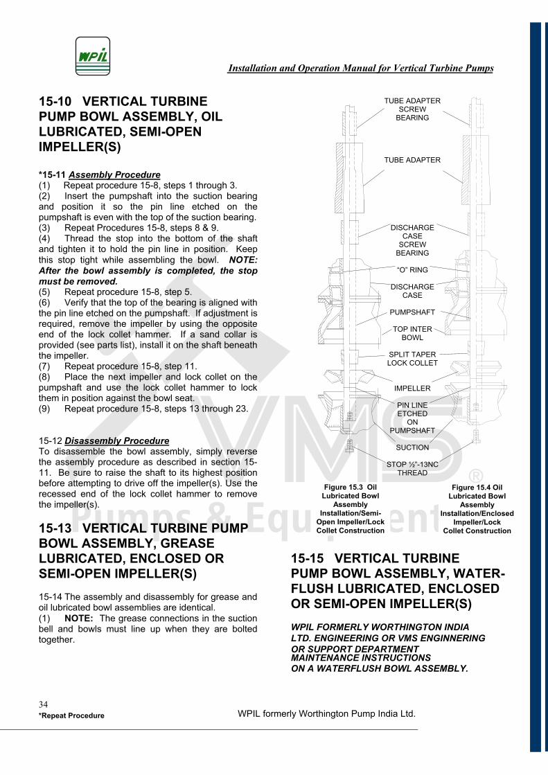
Installation and Operation Manual for Vertical Turbine Pumps
WPIL formerly Worthington Pump India Ltd.*Repeat Procedure34
15-10 VERTICAL TURBINEPUMP BOWL ASSEMBLY, OIL LUBRICATED, SEMI-OPEN IMPELLER(S)
*15-11 Assembly Procedure(1) Repeat procedure 15-8, steps 1 through 3.(2) Insert the pumpshaft into the suction bearing and position it so the pin line etched on the pumpshaft is even with the top of the suction bearing.(3) Repeat Procedures 15-8, steps 8 & 9.(4) Thread the stop into the bottom of the shaft and tighten it to hold the pin line in position. Keep this stop tight while assembling the bowl. NOTE:After the bowl assembly is completed, the stop must be removed.(5) Repeat procedure 15-8, step 5.(6) Verify that the top of the bearing is aligned with the pin line etched on the pumpshaft. If adjustment is required, remove the impeller by using the opposite end of the lock collet hammer. If a sand collar is provided (see parts list), install it on the shaft beneath the impeller.(7) Repeat procedure 15-8, step 11.(8) Place the next impeller and lock collet on the pumpshaft and use the lock collet hammer to lock them in position against the bowl seat.(9) Repeat procedure 15-8, steps 13 through 23.
15-12 Disassembly ProcedureTo disassemble the bowl assembly, simply reverse the assembly procedure as described in section 15-11. Be sure to raise the shaft to its highest position before attempting to drive off the impeller(s). Use the recessed end of the lock collet hammer to remove the impeller(s).
15-13 VERTICAL TURBINE PUMP BOWL ASSEMBLY, GREASE LUBRICATED, ENCLOSED OR SEMI-OPEN IMPELLER(S) 15-14 The assembly and disassembly for grease and oil lubricated bowl assemblies are identical.(1) NOTE: The grease connections in the suction bell and bowls must line up when they are bolted together.
15-15 VERTICAL TURBINE PUMP BOWL ASSEMBLY, WATER- FLUSH LUBRICATED, ENCLOSED OR SEMI-OPEN IMPELLER(S) WPIL FORMERLY WORTHINGTON INDIALTD. ENGINEERING OR VMS ENGINNERINGOR SUPPORT DEPARTMENTMAINTENANCE INSTRUCTIONS ON A WATERFLUSH BOWL ASSEMBLY.
TUBE ADAPTER SCREW
BEARING
TUBE ADAPTER
DISCHARGECASE
SCREWBEARING
“O” RING
DISCHARGECASE
PUMPSHAFT
TOP INTER BOWL
SPLIT TAPER LOCK COLLET
IMPELLER
PIN LINE ETCHED
ONPUMPSHAFT
SUCTION
STOP ½”-13NC THREAD
Figure 15.3 Oil Lubricated Bowl
Assembly Installation/Semi-
Open Impeller/Lock Collet Construction
Figure 15.4 Oil Lubricated Bowl
Assembly Installation/Enclosed
Impeller/LockCollet Construction
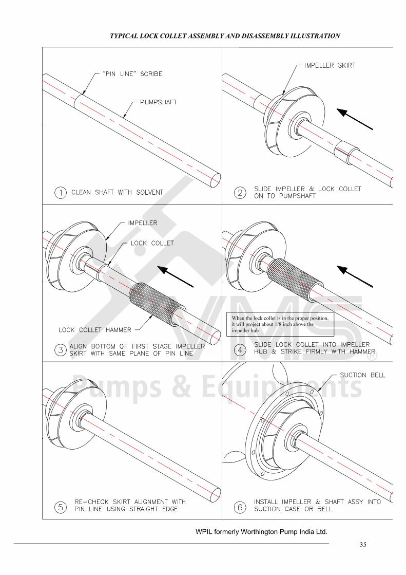
35
TYPICAL LOCK COLLET ASSEMBLY AND DISASSEMBLY ILLUSTRATION
When the lock collet is in the proper position,
it will project about 1/8 inch above the
impeller hub
et is i e prWh he lo
it w oject ut 1/8 abo
im ub
hen th in th
will pro 8 inch
peller hu
position,per
e the
WPIL formerly Worthington Pump India Ltd.
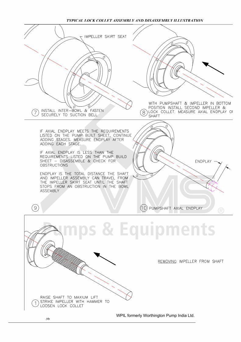
36
TYPICAL LOCK COLLET ASSEMBLY AND DISASSEMBLY ILLUSTRATION
WPIL formerly Worthington Pump India Ltd.
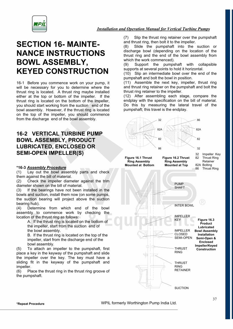
Installation and Operation Manual for Vertical Turbine Pumps
WPIL formerly Worthington Pump India Ltd.*Repeat Procedure37
SECTION 16- MAINTE-NANCE INSTRUCTIONS BOWL ASSEMBLY,KEYED CONSTRUCTION 16-1 Before you commence work on your pump, it will be necessary for you to determine where the thrust ring is located. A thrust ring maybe installed either at the top or bottom of the impeller. If the thrust ring is located on the bottom of the impeller, you should start working from the suction end of the bowl assembly. However, if the thrust ring is located on the top of the impeller, you should commence from the discharge end of the bowl assembly.
16-2 VERTICAL TURBINE PUMP BOWL ASSEMBLY, PRODUCT LUBRICATED, ENCLOSED OR SEMI-OPEN IMPELLER(S)
*16-3 Assembly Procedure(1) Lay out the bowl assembly parts and check them against the bill of material.(2) Check the impeller diameter against the trim diameter shown on the bill of material.(3) If the bearings have not been installed in the bowls and suction, install them now (on some pumps, the suction bearing will project above the suction bearing hub).(4) Determine from which end of the bowl assembly to commence work by checking the location of the thrust ring as follows:
A. If the thrust ring is located on the bottom ofthe impeller, start from the suction end ofthe bowl assembly.B. If the thrust ring is located on the top of theimpeller, start from the discharge end of thebowl assembly.
(5) To attach an impeller to the pumpshaft, first place a key in the keyway of the pumpshaft and slide the impeller over the key. The key must have a sliding fit in the keyway of the pumpshaft and impeller.(6) Place the thrust ring in the thrust ring groove of the pumpshaft.
(7) Slip the thrust ring retainer over the pumpshaft and thrust ring, then bolt it to the impeller. (8) Slide the pumpshaft into the suction or discharge bowl (depending on the location of the thrust ring and the end of the bowl assembly from which the work commenced).(9) Support the pumpshaft with collapsible supports at several points to hold it horizontal.(10) Slip an intermediate bowl over the end of the pumpshaft and bolt the bowl in position.(11) Assemble the next key, impeller, thrust ring and thrust ring retainer on the pumpshaft and bolt the thrust ring retainer to the impeller. (12) After assembling each stage, compare the endplay with the specification on the bill of material. Do this by measuring the lateral travel of the pumpshaft; this travel is the endplay.
PUMPSHAFT
INTER BOWL
IMPELLERKEY
IMPELLERCLOSEDSEMI-OPEN
THRUSTRING
THRUSTRINGRETAINER
SUCTION
32 Impeller Key 82 Thrust Ring Retainer 82A Bolting 86 Thrust Ring
Figure 16.1 Thrust Figure 16.2 Thrust Ring Assembly Ring Assembly Mounted at Bottom Mounted at Top
32
82A
82
86
Figure 16.3 Product
LubricatedBowl Assembly
InstallationSemi-Open &
EnclosedImpeller/Keyed Construction
86
82A
82
32
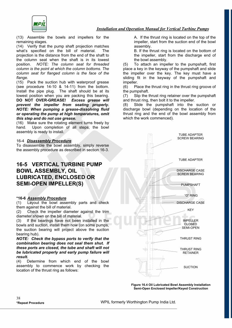
Installation and Operation Manual for Vertical Turbine Pumps
WPIL formerly Worthington Pump India Ltd.*Repeat Procedure38
(13) Assemble the bowls and impellers for the remaining stages.(14) Verify that the pump shaft projection matches what’s specified on the bill of material. The projection is the distance from the end of the shaft to the column seat when the shaft is in its lowest position. NOTE: The column seat for threaded column is the point at which the column bottoms. The column seat for flanged column is the face of the flange.(15) Pack the suction hub with waterproof grease (see procedure 14-10 & 14-11) from the bottom. Install the pipe plug. The shaft should be at its lowest position when you are packing this bearing. DO NOT OVER-GREASE! Excess grease will prevent the impeller from seating properly. NOTE: When pumping a grease-dissolving fluid or operating the pump at high temperatures, omit this step and do not use grease.(16) Make sure the rotating element turns freely by hand. Upon completion of all steps, the bowl assembly is ready to install.
16-4 Disassembly ProcedureTo disassemble the bowl assembly, simply reverse the assembly procedure as described in section 16-3.
16-5 VERTICAL TURBINE PUMP BOWL ASSEMBLY, OIL LUBRICATED, ENCLOSED OR SEMI-OPEN IMPELLER(S)
*16-6 Assembly Procedure(1) Layout the bowl assembly parts and check them against the bill of material. (2) Check the impeller diameter against the trim diameter shown on the bill of material.(3) If the bearings have not been installed in the bowls and suction, install them now (on some pumps, the suction bearing will project above the suction bearing hub). NOTE: Check the bypass ports to verify that the combination bearing does not seal them shut. If these ports are closed, the tube and shaft will not be lubricated properly and early pump failure will result.(4) Determine from which end of the bowl assembly to commence work by checking the location of the thrust ring as follows:
A. If the thrust ring is located on the top of the impeller, start from the suction end of the bowl assembly.B. If the thrust ring is located on the bottom of the impeller, start from the discharge end of the bowl assembly.
(5) To attach an impeller to the pumpshaft, first place a key in the keyway of the pumpshaft and slide the impeller over the key. The key must have a sliding fit in the keyway of the pumpshaft and impeller.(6) Place the thrust ring in the thrust ring groove of the pumpshaft.(7) Slip the thrust ring retainer over the pumpshaft and thrust ring, then bolt it to the impeller.(8) Slide the pumpshaft into the suction or discharge bowl (depending on the location of the thrust ring and the end of the bowl assembly from which the work commenced).
TUBE ADAPTER SCREW BEARING
TUBE ADAPTER
DISCHARGE CASE SCREW BEARING
PUMPSHAFT
“O” RING
DISCHARGE CASE
KEY
IMPELLERCLOSED
SEMI-OPEN
THRUST RING
THRUST RING RETAINER
SUCTION
Figure 16.4 Oil Lubricated Bowl Assembly Installation Semi-Open Enclosed Impeller/Keyed Construction
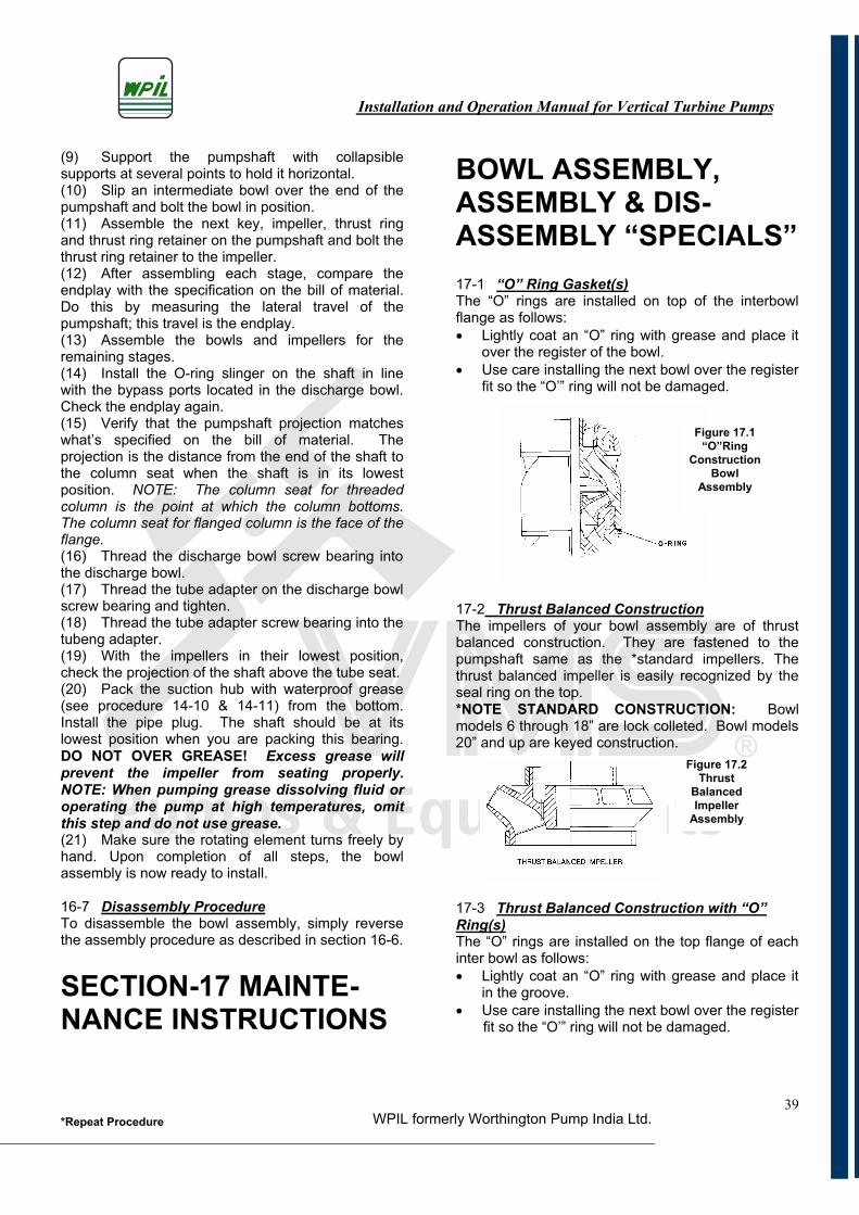
Installation and Operation Manual for Vertical Turbine Pumps
WPIL formerly Worthington Pump India Ltd.*Repeat Procedure39
(9) Support the pumpshaft with collapsible supports at several points to hold it horizontal.(10) Slip an intermediate bowl over the end of the pumpshaft and bolt the bowl in position.(11) Assemble the next key, impeller, thrust ring and thrust ring retainer on the pumpshaft and bolt the thrust ring retainer to the impeller. (12) After assembling each stage, compare the endplay with the specification on the bill of material. Do this by measuring the lateral travel of the pumpshaft; this travel is the endplay. (13) Assemble the bowls and impellers for the remaining stages. (14) Install the O-ring slinger on the shaft in line with the bypass ports located in the discharge bowl. Check the endplay again. (15) Verify that the pumpshaft projection matches what’s specified on the bill of material. The projection is the distance from the end of the shaft to the column seat when the shaft is in its lowest position. NOTE: The column seat for threaded column is the point at which the column bottoms. The column seat for flanged column is the face of the flange.(16) Thread the discharge bowl screw bearing into the discharge bowl. (17) Thread the tube adapter on the discharge bowl screw bearing and tighten. (18) Thread the tube adapter screw bearing into the tubeng adapter. (19) With the impellers in their lowest position, check the projection of the shaft above the tube seat. (20) Pack the suction hub with waterproof grease (see procedure 14-10 & 14-11) from the bottom. Install the pipe plug. The shaft should be at its lowest position when you are packing this bearing. DO NOT OVER GREASE! Excess grease will prevent the impeller from seating properly. NOTE: When pumping grease dissolving fluid or operating the pump at high temperatures, omit this step and do not use grease.(21) Make sure the rotating element turns freely by hand. Upon completion of all steps, the bowl assembly is now ready to install.
16-7 Disassembly ProcedureTo disassemble the bowl assembly, simply reverse the assembly procedure as described in section 16-6.
SECTION-17 MAINTE- NANCE INSTRUCTIONS
BOWL ASSEMBLY, ASSEMBLY & DIS- ASSEMBLY “SPECIALS” 17-1 “O” Ring Gasket(s)The “O” rings are installed on top of the interbowl flange as follows: Lightly coat an “O” ring with grease and place it
over the register of the bowl. Use care installing the next bowl over the register
fit so the “O’” ring will not be damaged.
17-2 Thrust Balanced ConstructionThe impellers of your bowl assembly are of thrust balanced construction. They are fastened to the pumpshaft same as the *standard impellers. The thrust balanced impeller is easily recognized by the seal ring on the top. *NOTE STANDARD CONSTRUCTION: Bowl models 6 through 18” are lock colleted. Bowl models 20” and up are keyed construction.
17-3 Thrust Balanced Construction with “O” Ring(s)The “O” rings are installed on the top flange of each inter bowl as follows: Lightly coat an “O” ring with grease and place it
in the groove. Use care installing the next bowl over the register
fit so the “O’” ring will not be damaged.
Figure 17.1 “O”Ring
ConstructionBowl
Assembly
Figure 17.2 Thrust
BalancedImpeller
Assembly
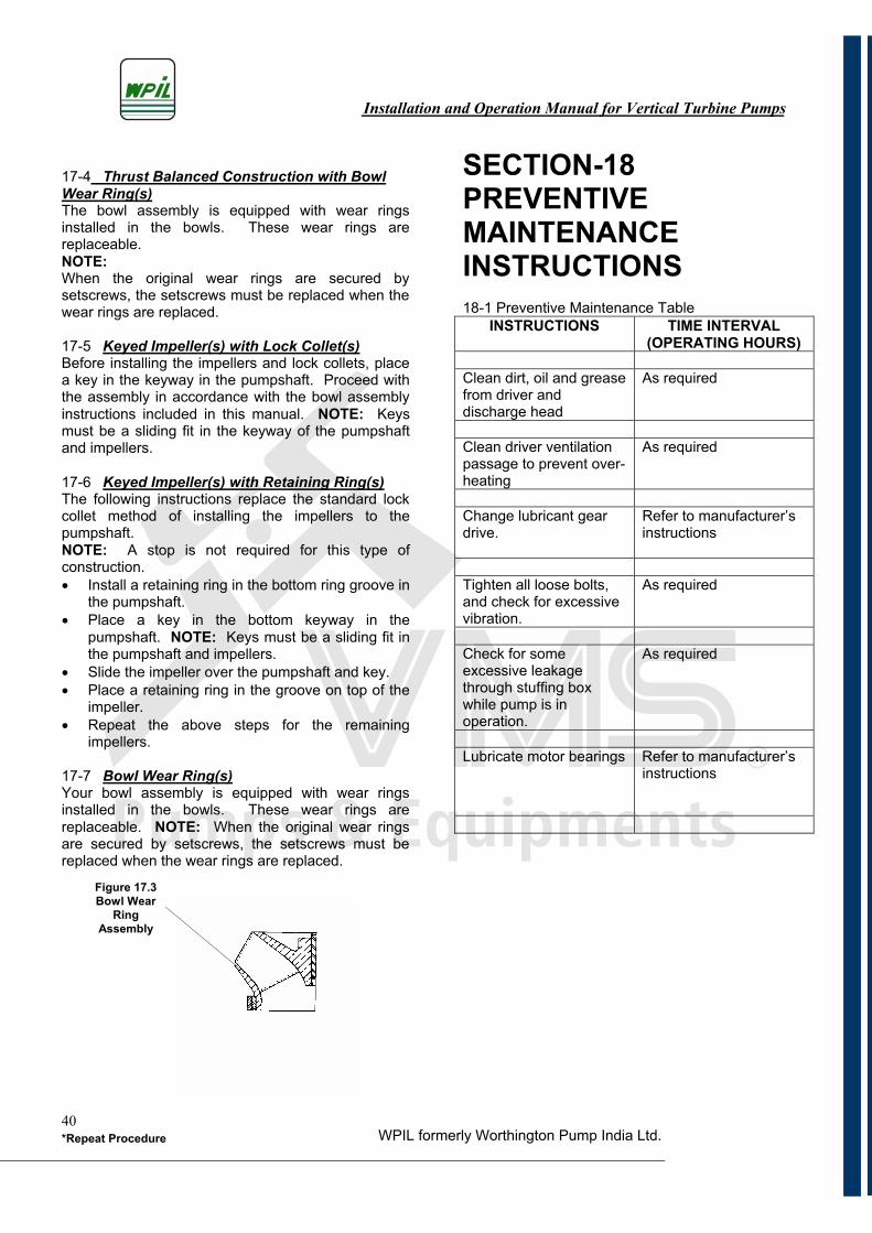
Installation and Operation Manual for Vertical Turbine Pumps
WPIL formerly Worthington Pump India Ltd.*Repeat Procedure40
17-4 Thrust Balanced Construction with Bowl Wear Ring(s)The bowl assembly is equipped with wear rings installed in the bowls. These wear rings are replaceable.NOTE:When the original wear rings are secured by setscrews, the setscrews must be replaced when the wear rings are replaced.
17-5 Keyed Impeller(s) with Lock Collet(s)Before installing the impellers and lock collets, place a key in the keyway in the pumpshaft. Proceed with the assembly in accordance with the bowl assembly instructions included in this manual. NOTE: Keys must be a sliding fit in the keyway of the pumpshaft and impellers.
17-6 Keyed Impeller(s) with Retaining Ring(s)The following instructions replace the standard lock collet method of installing the impellers to the pumpshaft.NOTE: A stop is not required for this type of construction. Install a retaining ring in the bottom ring groove in
the pumpshaft. Place a key in the bottom keyway in the
pumpshaft. NOTE: Keys must be a sliding fit in the pumpshaft and impellers.
Slide the impeller over the pumpshaft and key. Place a retaining ring in the groove on top of the
impeller. Repeat the above steps for the remaining
impellers.
17-7 Bowl Wear Ring(s)Your bowl assembly is equipped with wear rings installed in the bowls. These wear rings are replaceable. NOTE: When the original wear rings are secured by setscrews, the setscrews must be replaced when the wear rings are replaced.
SECTION-18PREVENTIVEMAINTENANCEINSTRUCTIONS18-1 Preventive Maintenance Table
INSTRUCTIONS TIME INTERVAL (OPERATING HOURS)
Clean dirt, oil and grease from driver and discharge head
As required
Clean driver ventilationpassage to prevent over- heating
As required
Change lubricant gear drive.
Refer to manufacturer’s instructions
Tighten all loose bolts, and check for excessive vibration.
As required
Check for some excessive leakage through stuffing box while pump is in operation.
As required
Lubricate motor bearings Refer to manufacturer’s instructions
Figure 17.3 Bowl Wear
RingAssembly
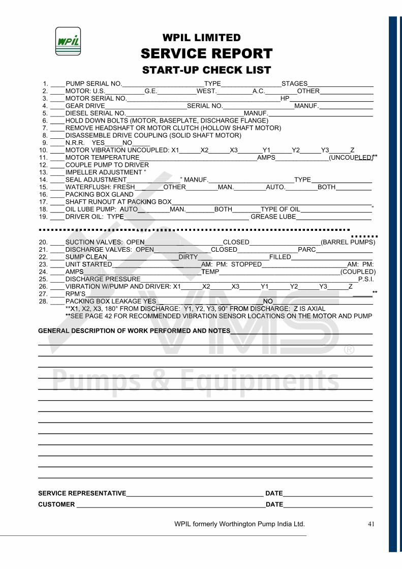
SERVICE REPORTSTART-UP CHECK LIST
41
1. ____ PUMP SERIAL NO._______________________TYPE_________________STAGES 2. ____ MOTOR: U.S.___________G.E.___________WEST.__________A.C._________OTHER 3. ____ MOTOR SERIAL NO.___________________________________________HP 4. ____ GEAR DRIVE_______________________SERIAL NO.____________________MANUF. 5. ____ DIESEL SERIAL NO._________________________________MANUF. 6. ____ HOLD DOWN BOLTS (MOTOR, BASEPLATE, DISCHARGE FLANGE) 7. ____ REMOVE HEADSHAFT OR MOTOR CLUTCH (HOLLOW SHAFT MOTOR) 8. ____ DISASSEMBLE DRIVE COUPLING (SOLID SHAFT MOTOR) 9. ____ N.R.R. YES_____NO_____
10. ____ MOTOR VIBRATION UNCOUPLED: X1______X2______X3_______Y1______Y2______Y3______Z **11. ____ MOTOR TEMPERATURE_________________________________AMPS_______________(UNCOUPLED)
12. ____ COUPLE PUMP TO DRIVER 13. ____ IMPELLER ADJUSTMENT ” 14. ____ SEAL ADJUSTMENT_______________” MANUF.________________________TYPE 15. ____ WATERFLUSH: FRESH________OTHER_________MAN._________AUTO._________BOTH 16. ____ PACKING BOX GLAND 17. ____ SHAFT RUNOUT AT PACKING BOX
”18. ____ OIL LUBE PUMP: AUTO_________MAN.________BOTH________TYPE OF OIL EBUL ESAERG ___________________________________EPYT :LIO REVIRD ____ .91
20. ____ SUCTION VALVES: OPEN______________________CLOSED____________________(BARREL PUMPS) 21. ____ DISCHARGE VALVES: OPEN________________CLOSED_________________PARC
DELLIF____________________YTRID____________________NAELC PMUS ____ .2223. ____ UNIT STARTED_________________________AM: PM: STOPPED________________________AM: PM: 24. ____ AMPS_________________________________TEMP__________________________________(COUPLED) 25. ____ DISCHARGE PRESSURE_____________________________________________________________P.S.I. 26. ____ VIBRATION W/PUMP AND DRIVER: X1______X2______X3______Y1______Y2______Y3______Z
**27. ____ RPM’S ON______________________________SEY EGAKAEL XOB GNIKCAP ____ .82
**X1, X2, X3, 180° FROM DISCHARGE: Y1, Y2, Y3, 90° FROM DISCHARGE: Z IS AXIAL **SEE PAGE 42 FOR RECOMMENDED VIBRATION SENSOR LOCATIONS ON THE MOTOR AND PUMP
SETON DNA DEMROFREP KROW FO NOITPIRCSED LARENEG
SSERVICE REPRESENTATIVE DATE
CUSTOMER DATE
WPIL LIMITED
N_____________ ______OPEN___________ ________
__________YTRID_________________________________ _____ _____AM_______ _____TESSU
SUCTION VADISCHARG
CPMU ESTART
S________ ___HARGE PR
TION W/PU
XOBGNIKX1, X2, X3
**SEE PA
EDLAREN
_______________
PACKINAUTO____ ___
________________________E
ES: ALVE
_______1, Y
VIBR
DEM
EYDISC
MM
FRE
___________SECHA Y1MEN D V
MROF
ON_____________________Y3, 0° FROM DISCHARON ENSO LOC ION
ON
____90SE
SETO
ONCH
CAT: ZON THE MOTO
GES O
WPIL formerly Worthington Pump India Ltd.
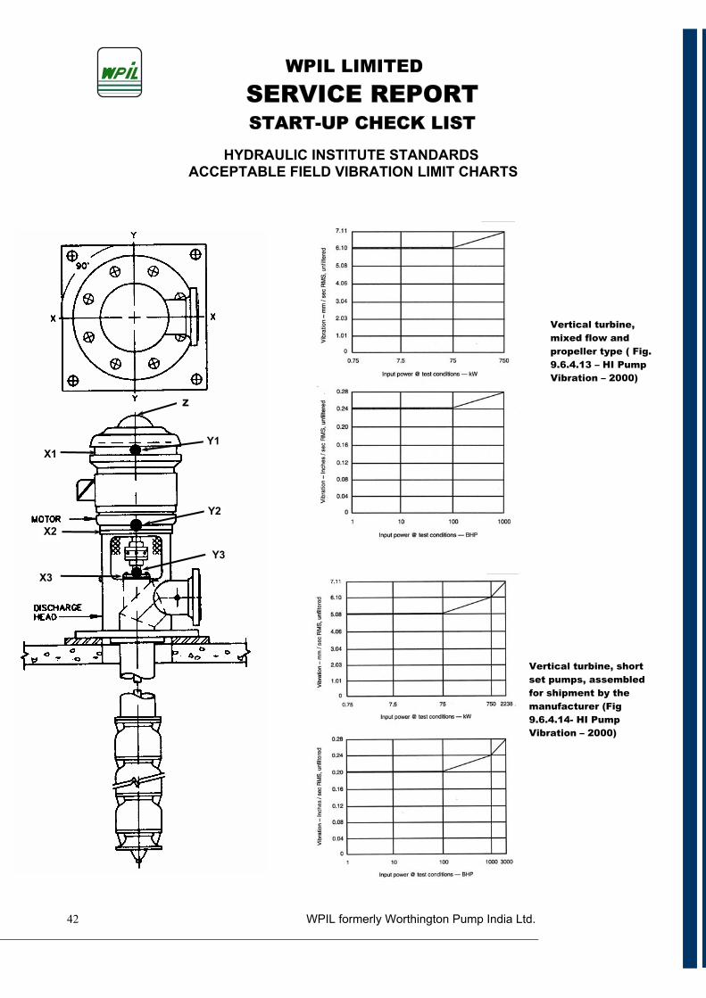
WPIL formerly Worthington Pump India Ltd.
SERVICE REPORTSTART-UP CHECK LIST
42
HYDRAULIC INSTITUTE STANDARDS ACCEPTABLE FIELD VIBRATION LIMIT CHARTS
z
X1
X2
X3
Y1
Y2
Y3
Vertical turbine, short
set pumps, assembled for shipment by the
manufacturer (Fig 9.6.4.14- HI Pump Vibration – 2000)
Vertical turbine,
mixed flow and propeller type ( Fig.
9.6.4.13 – HI Pump Vibration – 2000)
WPIL LIMITED
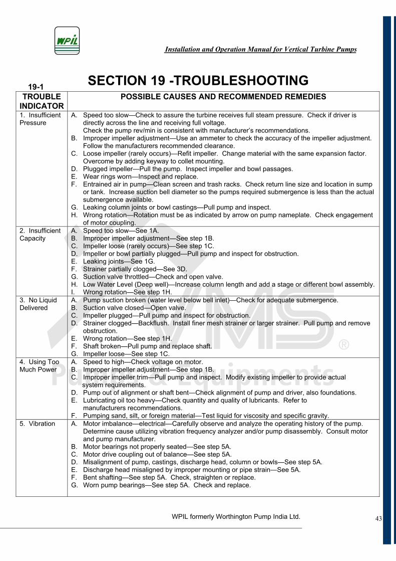
Installation and Operation Manual for Vertical Turbine Pumps
WPIL formerly Worthington Pump India Ltd.
SECTION 19 -TROUBLESHOOTING19-1TROUBLE
INDICATORPOSSIBLE CAUSES AND RECOMMENDED REMEDIES
1. InsufficientPressure
A. Speed too slow—Check to assure the turbine receives full steam pressure. Check if driver is directly across the line and receiving full voltage.Check the pump rev/min is consistent with manufacturer’s recommendations.
B. Improper impeller adjustment—Use an ammeter to check the accuracy of the impeller adjustment.Follow the manufacturers recommended clearance.
C. Loose impeller (rarely occurs)—Refit impeller. Change material with the same expansion factor.Overcome by adding keyway to collet mounting.
D. Plugged impeller—Pull the pump. Inspect impeller and bowl passages. E. Wear rings worn—Inspect and replace. F. Entrained air in pump—Clean screen and trash racks. Check return line size and location in sump
or tank. Increase suction bell diameter so the pumps required submergence is less than the actual submergence available.
G. Leaking column joints or bowl castings—Pull pump and inspect. H. Wrong rotation—Rotation must be as indicated by arrow on pump nameplate. Check engagement
of motor coupling. 2. InsufficientCapacity
A. Speed too slow—See 1A. B. Improper impeller adjustment—See step 1B. C. Impeller loose (rarely occurs)—See step 1C. D. Impeller or bowl partially plugged—Pull pump and inspect for obstruction. E. Leaking joints—See 1G. F. Strainer partially clogged—See 3D. G. Suction valve throttled—Check and open valve. H. Low Water Level (Deep well)—Increase column length and add a stage or different bowl assembly. I. Wrong rotation—See step 1H.
3. No LiquidDelivered
A. Pump suction broken (water level below bell inlet)—Check for adequate submergence. B. Suction valve closed—Open valve. C. Impeller plugged—Pull pump and inspect for obstruction. D. Strainer clogged—Backflush. Install finer mesh strainer or larger strainer. Pull pump and remove
obstruction.E. Wrong rotation—See step 1H. F. Shaft broken—Pull pump and replace shaft. G. Impeller loose—See step 1C.
4. Using TooMuch Power
A. Speed to high—Check voltage on motor. B. Improper impeller adjustment—See step 1B. C. Improper impeller trim—Pull pump and inspect. Modify existing impeller to provide actual system requirements. D. Pump out of alignment or shaft bent—Check alignment of pump and driver, also foundations. E. Lubricating oil too heavy—Check quantity and quality of lubricants. Refer to
manufacturers recommendations. F. Pumping sand, silt, or foreign material—Test liquid for viscosity and specific gravity.
5. Vibration A. Motor imbalance—electrical—Carefully observe and analyze the operating history of the pump.Determine cause utilizing vibration frequency analyzer and/or pump disassembly. Consult motor and pump manufacturer.
B. Motor bearings not properly seated—See step 5A. C. Motor drive coupling out of balance—See step 5A. D. Misalignment of pump, castings, discharge head, column or bowls—See step 5A. E. Discharge head misaligned by improper mounting or pipe strain—See 5A. F. Bent shafting—See step 5A. Check, straighten or replace. G. Worn pump bearings—See step 5A. Check and replace.
43
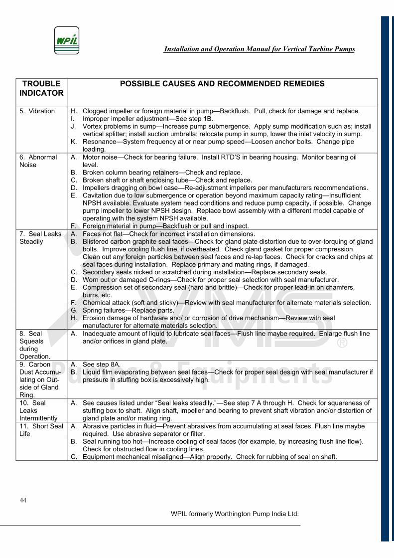
Installation and Operation Manual for Vertical Turbine Pumps
WPIL formerly Worthington Pump India Ltd.
TROUBLEINDICATOR
POSSIBLE CAUSES AND RECOMMENDED REMEDIES
5. Vibration H. Clogged impeller or foreign material in pump—Backflush. Pull, check for damage and replace. I. Improper impeller adjustment—See step 1B. J. Vortex problems in sump—Increase pump submergence. Apply sump modification such as; install
vertical splitter; install suction umbrella; relocate pump in sump, lower the inlet velocity in sump. K. Resonance—System frequency at or near pump speed—Loosen anchor bolts. Change pipe
loading.6. AbnormalNoise
A. Motor noise—Check for bearing failure. Install RTD’S in bearing housing. Monitor bearing oil level.
B. Broken column bearing retainers—Check and replace. C. Broken shaft or shaft enclosing tube—Check and replace.D. Impellers dragging on bowl case—Re-adjustment impellers per manufacturers recommendations. E. Cavitation due to low submergence or operation beyond maximum capacity rating—Insufficient
NPSH available. Evaluate system head conditions and reduce pump capacity, if possible. Change pump impeller to lower NPSH design. Replace bowl assembly with a different model capable of operating with the system NPSH available.
F. Foreign material in pump—Backflush or pull and inspect. 7. Seal LeaksSteadily
A. Faces not flat—Check for incorrect installation dimensions. B. Blistered carbon graphite seal faces—Check for gland plate distortion due to over-torquing of gland
bolts. Improve cooling flush line, if overheated. Check gland gasket for proper compression.Clean out any foreign particles between seal faces and re-lap faces. Check for cracks and chips at seal faces during installation. Replace primary and mating rings, if damaged.
C. Secondary seals nicked or scratched during installation—Replace secondary seals. D. Worn out or damaged O-rings—Check for proper seal selection with seal manufacturer.
E. Compression set of secondary seal (hard and brittle)—Check for proper lead-in on chamfers, burrs, etc.
F. Chemical attack (soft and sticky)—Review with seal manufacturer for alternate materials selection. G. Spring failures—Replace parts. H. Erosion damage of hardware and/ or corrosion of drive mechanism—Review with seal
manufacturer for alternate materials selection. 8. SealSquealsduringOperation.
A. Inadequate amount of liquid to lubricate seal faces—Flush line maybe required. Enlarge flush line and/or orifices in gland plate.
9. Carbon Dust Accumu-lating on Out- side of Gland Ring.
A. See step 8A. B. Liquid film evaporating between seal faces—Check for proper seal design with seal manufacturer if
pressure in stuffing box is excessively high.
10. Seal LeaksIntermittently
A. See causes listed under “Seal leaks steadily.”—See step 7 A through H. Check for squareness of stuffing box to shaft. Align shaft, impeller and bearing to prevent shaft vibration and/or distortion of gland plate and/or mating ring.
11. Short Seal Life
A. Abrasive particles in fluid—Prevent abrasives from accumulating at seal faces. Flush line maybe required. Use abrasive separator or filter.
B. Seal running too hot—Increase cooling of seal faces (for example, by increasing flush line flow).Check for obstructed flow in cooling lines.
C. Equipment mechanical misaligned—Align properly. Check for rubbing of seal on shaft.
44

NOTES
45
Installation and Operation Manual for Vertical Turbine Pumps
WPIL formerly Worthington Pump India Ltd.
NOTES
46
Installation and Operation Manual for Vertical Turbine Pumps
WPIL formerly Worthington Pump India Ltd.
RReepppaaaarrrraaaaccciiióóóónnnIInnssttaallacciióónn
MMMMeedición
IInnfraaeessttrrruucturaEEEnnssaaammmmm
bbbbblllleeeIIInnssttrruummm
eeeennttaacciónJuan Gutemberg 438 / G 7 y 8 Tel. (56-55) 556606 · Fax. (56-55) 556607 · Cel. (09) 91589966E - mail: [email protected] · www.vms.cl · Antofagasta Chile © 2009
El departamento de servicios de VMS, se crea en el año 1996, con el objetivo de entregar el apoyo técnico postventa a nuestra cartera de clientes de la zonanorte.A partir del año 2004 comienza la etapa de elaboración y ejecución de proyectos relacionados al giro de bombas hidráulicas, logrando gran prestigio ennuestra amplia cartera comercial que abarcaba la primera y segunda región de nuestro país. A partir del plan de reestructuración proyectado por la empresa, además de la ampliación de nuestra cartera de cliente, cubriendo prácticamente todo el país y parte de América del sur, el departamento de servicios de VMS ha invertido sistemáticamente en equipos e instrumentos de alta tecnología para un óptimo desempeño de las labores de los distintosprofesionales que cuenta el área de servicios.
Departamento de servicios

Juan Gutemberg 438 / G 7 y 8 · Tel. (56-55) 556606 · Fax. (56-55) 556607E - mail: [email protected] · www.vms.cl · Antofagasta Chile © 2009


