Distributed by Raccordi in PVC-U U-PVC fittings Raccords ...

MANUAL VALVESPVC-U
The PVC-U manual valves line consists of a comprehensive range of ball valves, butterfly valves, diaphragm valves, check valves, sediment strainers,
air release valves, foot valves and angle seat valves for use in the construction of process and service lines for conveying pressurised industrial fluids and for maximum
operating temperatures of no more than 60°C
PV
C-U

PVC-UGeneral characteristicsReference standardsApprovals and quality marksSolvent welding instructions
page 2page 4page 6page 8
VKD DN 10÷50DUAL BLOCK® 2-way ball valve page 15
VKD DN 65÷100DUAL BLOCK® 2-way ball valve page 31
VKRDUAL BLOCK® regulating ball valve page 45
TKDDUAL BLOCK® 3-way ball valve page 59
VXE DN 10÷50Easyfit 2-way ball valve page 75
VXE DN 65÷100Easyfit 2-way ball valve page 89
VEE DN 10÷50Easyfit 2-way ball valve page 103
VEE DN 65÷100Easyfit 2-way ball valve page 117
SXE-SSE DN 10÷50Easyfit True Union ball and spring check valve page 131
SXE-SSE DN 65÷100Easyfit True Union ball and spring check valve page 149
FEButterfly valve page 165
FKButterfly valve page 179
DKDIALOCK® 2-way diaphragm valve page 199
VMDiaphragm valve page 215
CMCompact diaphragm valve page 227
VM-RMMini-valve and diaphragm cock valve page 237
RVSediment strainer page 243
VVAngle seat valve page 255
VRCheck valve page 265
VAAir release valve page 275
VZFoot valve page 283
CRWafer check valve page 291
Key abbreviations page 297
MANUAL VALVES
IN PVC-U
CONTENTS

PVC-U
Developed in 1930 in Germany, PVC-U (rigid polyvinyl chloride – unplasticized) is obtained through the polymerization of a vinyl chloride monomer. The presence of chlorine in the PVC-U molecule results in a high performance resin, in terms of thermal stability and chemical and mechanical resistance, up to temperatures of 60° C.
The different formulations obtained by adding suitable additives and stabi-lizers render the PVC-U the most versatile of all plastic materials, allowing it to be adapted to many applications involving fluids under pressure.PVC-U represents one of the more economic solutions in the field of ther-moplastic and metal materials for resolving problems in the transport of corrosive chemical fluids, and in the distribution and treatment of water in general. The mains reasons for this preference are the unique characteristics of the resin, which include:• Good chemical resistance: PVC-U resins have excellent chemical resist-
ance to most acids and alkalis, paraffin/aliphatic hydrocarbons and saline solutions. It is not recommended for the transport of polar organic com-pounds, including some types of chlorinated and aromatic solvents. PVC-U resins are also fully compatible with the transport of foodstuffs, deminer-alised water, potable water and unconditioned water, as provided for by current national and international standards.
• Good thermal stability: PVC-U resins have good thermal stability in the temperature range between 20°C and 50°C and are typically used in in-dustrial and water supply applications, guaranteeing excellent mechanical strength, sufficient rigidity for the purpose, reduced thermal expansion co-efficients and high factors of safety in service. PVC-U compounds are also resistant to combustion with a flash point of 399°C. The flame, in fact, only persists if the oxygen concentration is twice that of atmospheric or in the presence of a flame from an external source. Flash point: 399° C. Oxygen index: 45%. UL 94 class: V0. Thanks to the reduced coefficient of thermal conductivity (λ = 0.15 W/m °C according to ASTM C177) the use of PVC-U resin for transporting hot fluids reduces heat loss and virtually eliminates condensation problems.
• Good mechanical strength: PVC-U resins are characterised by their low permeability to oxygen and reduced water absorption (0.1% at 23°C according to ASTM D 570). The thermal stability of the material leads to good impact resistance and the capacity to support service pressures of 4 – 6 – 10 – 16 bar at 20°C.
• Resistance to ageing: PVC-U resins have a high circumferential breaking strength (Minimum Required Strength MRS ≥ 25.0 MPa at 20°C) and allow long installation lifetimes without showing any signs of significant physi-cal-mechanical deterioration.
GENERAL CHARACTERISTICS
2

DensityTest method ISO 1183 - ASTM D792Unit of measurement g/cm3
Value 1.38
Modulus of elasticityTest method ISO 527Unit of measurement MPa = N/mm2
Value 3200
IZOD notched impact strength at 23°CTest method ASTM D256Unit of measurement J/mValue 50
Ultimate elongationTest method ISO 527Unit of measurement %Value 50
Shore hardnessTest method ISO 868Unit of measurement Shore DValue 80
Tensile strengthTest method ISO 527Unit of measurement MPa = N/mm2
Value 50
VICAT softening point (B/50)Test method ISO 306Unit of measurement °CValue 76
Heat distortion temperature HDT (0.46 N/mm2)Test method ASTM D648Unit of measurement °CValue 86
Thermal conductivity at 23° CTest method DIN 52612-1 - ASTM C177Unit of measurement W/(m °C)Value 0.16
Coefficient of linear thermal expansionTest method DIN 53752 - ASTM D696Unit of measurement m/(m °C)Value 8 x 10⁻⁵
Limiting Oxygen IndexTest method ISO 4859-1 - ASTM D2863Unit of measurement %Value 45
3

REFERENCE
• ANSI B16.5 Pipe flanges and flanged fittings-NPS 1/2 to NPS 24 mm / inch• ASTM D 2464 Standard Specification for Threaded Poly Vinyl Chloride (PVC) Plastic Pipe
Fittings• ASTM D 2467 Standard Specification for Poly Vinyl Chloride (PVC) Plastic Pipe Fittings,
Schedule 80• BS 10 Specification for flanges and bolts for pipes, valves and fittings• BS 1560 Flanges for pipes, valves and fittings (Class designated). Steel, cast iron
and copper alloy flanges. Specification for steel flanges • BS 4504 Flanges for pipes, valves and fittings (PN designated).• DIN 2501 Flanges, dimensions• DIN 2999 Whitworth thread for threaded pipes and fittings• DIN 3202 Overall valve dimensions• DIN 3441-2 Dimensions of PVC-U ball valves• DIN 8062 Dimensions of PVC-U pipes• DIN 8063 Dimensions of PVC-U fittings• DIN 16962 PVC-C fittings for butt-welding or socket fusion, dimensions• DIN 16963 Pipe connections and pipe components for pressurised fluids in HDPE• DVS 2204 - 2221 Solvent welding of thermoplastic materials PVC-U• EN 558-1 Industrial valves - face-to-face and centre-to-face dimensions of metal
valves for use in flanged pipe systems - Part 1: PN designated valves • EN 1092-1 Flanges and their joints - Circular flanges for pipes, valves and accessories
- Part 1: Steel flanges, PN designated • EN ISO 1452 Characteristics of fittings and pipes in PVC-U for piping systems intended
for water supply
STANDARDSProduction of the PVC-U lines is carried out according to the highest quality standards and in full compliance with the environmental restrictions set by the applicable laws in force and in accordance with ISO 14001. All products are made in accordance with the quality guarantee system in compliance with ISO 9001.
4

• EN ISO 15493 Specifications for components and the system (Pipes, Fittings and Valves)
in ABS, PVC-U, PVC-C for industrial applications• EN ISO 16135 Industrial valves - Ball valves of thermoplastic material• EN ISO 16136 Industrial valves - Butterfly valves of thermoplastic material• EN ISO 16137 Industrial valves - Check valves of thermoplastic material• EN ISO 16138 Industrial valves - Diaphragm valves of thermoplastic material• ISO 7 PVC-U fittings with threaded connections for pressure-tight joints• ISO 161-1 Dimensions of PVC-U pipes and fittings - metric series• ISO 228-1 PVC-U fittings with threaded connections• ISO 727 PVC-U pipes and fittings. Dimensions and tolerances - metric series• ISO 5211 Part-turn actuator attachments• ISO 5752 Metal valves for use in flanged pipe systems; Face-to-face and centre-to-
face dimensions• ISO 7005-1 Metal flanges; part 1: steel flanges• ISO 9393 Thermoplastics valves - pressure test methods and requirements• JIS B 2220 Flanges for metal pipes• JIS K 6743 Polyvinyl chloride (PVC-U) pipe fittings for water supply• UNI 11242 Solvent welding of PVC-U pipes, fittings and valves
5

APPROVALS AND
• ABS FIP PVC-U valves have been recongnised as suitable for conveying, treat-
ing domestic and air conditioning waters on board ships and other units classified by the American Bureau of Shipping (ABS)
• ACS FIP PVC-U ball valves are certified as suitable for coming into contact with
water intended for human consumption according to the Attestation de conformité sanitaire (ACS)
• Bureau Veritas FIP PVC-U valves have been recognised as suitable for conveying, treating
domestic and air conditioning waters on board ships and other units clas-sified by the Bureau Veritas - Marine Division
• DIBt FIP PVC-U valves have been tested and certified by DIBt (Deutsches Insti-
tut für Bautechnik)
• GOST-R - EAC FIP PVC-U valves are GOST-R and EAC certified in accordance with Rus-
sian regulations on Safety, Hygiene and Quality
• NSF FIP PVC-U ball valves are listed according to the NSF/ANSI Standard 61 -
Drinking Water System Components - Health Effects
QUALITY MARKS
6
TA-Luft • TA-Luft FIP PVC-U valves have been tested and certified ac-
cording to “TA-Luft” by MPA Stuttgart in compliance with the Technical Instruction on Air Quality Control TA-Luft/ VDI 2440
• UKR SEPRO FIP PVC-U valves are certified in accordance with
Ukrainian regulations on Safety and Quality
• WRAS FIP PVC-U valves are recognised by the WRAS (Water
Regulation Advisory Scheme - UK)
7

SOLVENT WELDINGINSTRUCTIONS
Fig. 2
Fig. 1
Solvent welding, or cement jointing, is the longitudinal joining system for connecting rigid PVC-U pipes and fittings.The "cementing" is carried out using adhesives/cements obtained by dissolving PVC-U polymer in a solvent mixture. This solvent liquefies the walls of the pipe and/or fitting, allowing the constituent material to chemically combine and be subse-quently welded. Chemical welding allows permanent joints be achieved possessing chemical and mechanical strength characteristics identical to those of the pipes and fittings joined. The adhesives/solvent cements must be selected according to the type of thermoplastic resin to weld, in that the nature of the solvents vary, as does the weld material contained in them. It must be remembered, therefore, that all the solvent cements designed for joining thermoplastic pipes and fittings must be used to join pipes, fittings and valves of the same material.Before starting any solvent welding operations, the efficiency and condition of the equipment used and the pieces to be assembled must be verified, in particular the uniformity, fluidity and expiry date of the solvent cement. 1) Cut the pipe perpendicular to its axis to obtain a clean square section, preferably
using a wheeled pipe cutter designed specifically for thermoplastic pipes (fig. 1).2) Chamfer the outer edges of the pipe in order to ensure that it enters the socket
of the fitting at an angle of 15°. The chamfering operation must be carried out at all costs, otherwise the lack of chamfer can lead to the solvent being scraped off the surface of the fitting, thus compromising the effectiveness of the joint. The chamfering must be carried out using the appropriate chamfering tool (fig. 2).
3) Measure the depth of the socket of the fitting to the internal shoulder and mark the corresponding distance on the end of the pipe (fig. 3 and 4). For more de-tails, refer to the "Socket depth, cement and chamfer length" table.
4) Using an clean paper towel or applicator soaked in Cleaner-Primer, remove any traces of dirt or grease from the outer surface of the pipe for the entire cement-ing length. Repeat the same operation on the internal surface of the socket of the fitting: leaving the surfaces softened (fig. 5).
Leave the surfaces to dry for a few minutes before applying the solvent cement. Remember that, in addition to cleaning the joint surfaces, the Cleaner-Primer also performs the important role of softening and preparing the surface to receive the solvent, an operation that enables a perfect joint to be obtained.
5) Apply the solvent cement in a uniform manner longitudinally over both parts to be assembled (outer surface of the pipe and internal coupling surface of the fit-ting) using an applicator or suitably sized coarse brush.
For more detailed information, refer to the “Brush-applicator characteristics and dimensions” table.
Fig. 3 Fig. 4 Fig. 5
8

Fig. 6 It is advisable to use an applicator/brush of dimension not less than half the di-
ameter of the pipe. The solvent cement must be applied along the entire length of the joining surface of both the pipe and the fitting:
- for the entire joint length of the pipe previously marked on the outer surface (fig. 6)
- for the entire depth of the socket as far as the internal shoulder (fig.7)6) Fully insert the pipe into the fitting immediately and without any rotation. Only
after this operation will it be possible to slightly rotate both ends (max. 1/4 of a turn between pipe and fitting). This rotation movement will render the layer of applied solvent cement more uniform (fig. 8)
7) The pipe must be inserted in the fitting as soon and as quick as possible (after no more than 20-25 seconds is recommended). Depending on the external diameter of the pipe and, as a result, possible handling difficulties, the insertion of the pipe into the fitting must be carried out:
- manually by one person for external diameters < 90 mm. - manually by two people for external diameters from d 90 to d < 160 mm. - using mechanical pipe-pullers for external diameters > 160 mm.8) Immediately after fully inserting the pipe in the fitting, apply pressure to the
joined parts for a few seconds. Then use crepe paper or a clean cloth to remove any excess solvent cement from the outer surfaces, and from internal surfaces where possible (fig. 9).
9) Solvent cement drying: the joined parts must be left to stand in order to allow the solvent cement to set naturally without generating any unnecessary stress. The setting time depends on the amount of stress that the joint will be placed under.
In particular, the following minimum setting times must be respected according to the ambient temperature:
• before handling the joint: - from 5 to 10 minutes for ambient T. > 10°C - from 15 to 20 minutes for ambient T. < 10°C
• for repair joints on pipes of any size or pressure not subject to hydraulic testing: - 1 hour for each atm of applied pressure
• for joints in pipes and fittings of any diameter subject to pressure testing up to PN 16:
- minimum 24 hours The solvent cement setting times indicated are valid at ambient temperature (ap-
prox. 25°C.). For particular climatic conditions (humidity, temperature, etc…), we recommend you contact our technical services department and/or the solvent cement manufacturer for more information (fig. 10 and 11).
Fig. 7
Fig. 8
Fig. 9 Fig. 10
5’/10’ min. > 10° C
15’/20’ min. < 10° C
Fig. 11
16 bar > 24 h
1 bar = 1 h
9

SOCKET DEPTH, CEMENT AND CHAMFER LENGTH
External diameterde (mm)
Cementing lengthL (mm)
ChamferSm (mm)
Metric series de (mm)
BS series (inches)
Metric series BS series
16 3/8” 14 14.5
20 1/2” 16 16.5 1.5
25 3/4” 18.5 19.5 3
32 1” 22 22.5 3
40 1” 1/4 26 27 3
50 1” 1/2 31 30 3
63 2” 37.5 36 5
75 2” 1/2 43.5 43.5 5
90 3” 51 50.5 5
110 4” 61 63 5
125 - 68.5 - 5
140 5” 76 76 5
160 6” 86 90 5
180 - 96 - 5÷6
200 - 106 - 5÷6
225 8” 118.5 115.5 5÷6
250 - 131 - 5÷6
280 10” 146 142.5 5÷6
315 12” 163.5 168 5/6
CHARACTERISTICS AND DIMENSIONS OF BRUSHES- APPLICATORS
External diameter Type and dimensions of Brush or Applicatorde (mm) (inches)
16 - 25 3/8” - 3/4” Round (8 - 10 mm)
32 - 63 1” - 2” Round (20 - 25 mm)
75 - 160 2” 1/2 - 6” Rectangular / round (45 - 50 mm)
>160 >6” Rectangular / cylindrical (45 - 50 mm)
>160 - 315 >6” - 12” Rectangular / cylindrical (60 - 65 mm)
10

• In the case where the external diameter of the pipe and the internal diameter of the fitting are at opposite extremes of their tolerance values, the dry pipe cannot be in-serted in the dry socket of the fitting. Insertion will only be possible after having ap-plied the Cleaner and Solvent Cement to both parts to be joined.
• The solvent cement is manufactured from the same PVC resin used for the production of the pipes, fittings and valves. Unless otherwise specified, the solvent cement used on the surfaces to join must also be usable with the following tolerances:
- maximum interference 0.2 mm. - maximum clearance 0.6 mm. • When using the Cleaner and Solvent Cement, the following precautions should be
adopted:- Use gloves and safety glasses to protect hands and eyes.- Use the Cleaner and Solvent Cement in a working environment with sufficient ventila-
tion to avoid the formation of pockets of air containing concentrations of evaporated solvent, which can irritate the respiratory tract and eyes.
- Due to the volatile nature of the solvents in the cleaner and cement, the containers must be closed immediately after use.
- Solvents in the gaseous phase tend to form flammable mixtures. Therefore, remove any ignition sources such as welding operations, accumulation of electrostatic charg-es, etc. from the work area, and do not smoke. In all cases, it is advisable to adhere strictly to the solvent cement manufacturer's instructions written on the packaging.
- In order to prevent a deterioration in the performance of the cleaner and solvent cement, the joining operations should be carried out within an ambient temperature range of between + 5 and + 40° C.
• The amount of solvent cement used on the joints depends on a number of factors (en-vironmental conditions, pipe size, cement viscosity, operator experience, etc.) which are often difficult to quantify. In this respect, Table “Rigid PVC-U pipes and fittings. Theoretical solvent cement consumption” reports the approximate quantities of ce-ment normally used for joining various diameter pipes and fittings.
• After having completed all the joints and prior to putting the lines into service, make sure that the insides of the pipes and fittings are completely free of any solvent trac-es/vapours. This will prevent contamination of the fluids conveyed.
• Table “Most common defects” reports the most common types of defect found if the correct solvent welding procedure is not followed.
WARNINGS
11

RIGID PVC-U PIPES AND FITTINGS THEORETICAL SOLVENT CEMENT CONSUMPTION
MOST COMMON DEFECTS
Pipe/Fitting diameter Number of joints per kg of solvent cement
d (mm) d (inches)
16 3/8” 550
20 1/2” 500
25 3/4” 450
32 1” 400
40 1” 1/4 300
50 1” 1/2 200
63 2” 140
75 2” 1/2 90
90 3” 60
110 4” 40
125 - 30
140 5” 25
160 6” 15
180 - 12
200 - 10
225 8” 6
250 - 4
280 10” 2
315 12” 2
Solvent cement too fluid (incorrect diluent addition)Immediate effect Cementing failure.
Consequence Joint separation or leaks from between the pipe and fitting.
Excess solvent cementImmediate effect Internal and external runs beyond the joint zone.
Consequence Weakening of the outer surface of the joint area and formation of bubbles with micro-cracks/sources of fracture in the base material.
Excessively dense solvent cement due to evaporated solventImmediate effect Cementing failure.
Consequence Joint separation or leaks from between the pipe and fitting.Possible surface cracks triggering cracks in the base material.
Insufficient and/or incorrect distribution of solvent cementImmediate effect Cementing failure or local weakness.
Consequence Joint separation or leaks from between the pipe and fitting.
Incorrect pipe insertion (incomplete, excessive, misaligned)Immediate effect Imperfect joint.
Consequence Transmission of mechanical stresses from the pipe to the fitting and/or leaks from the joint.
Impurities and/or humidity on the surfaces of the parts to joinImmediate effect Imperfect joint.
Consequence Joint separation or leaks (fluid seepage) from between the pipe and fitting.
12

13


VKD DN 10÷50PVC-U
DUAL BLOCK® 2-way ball valve

16
Technical specificationsConstruction 2-way True Union ball valve with locked carrier and
union nuts.Size range DN 10 ÷ 50Nominal pressure PN 16 with water at 20 °CTemperature range 0 °C ÷ 60 °CCoupling standards Solvent welding: EN ISO 1452, EN ISO 15493, BS
4346-1, DIN 8063, NF T54-028, ASTM D 2467, JIS K 6743. Pipe coupling as per EN ISO 1452, EN ISO 15493, DIN 8062, NF T54-016, ASTM D 1785, JIS K 6741
Thread: ISO 228-1, DIN 2999, ASTM D 2464, JIS B 0203
Flanging system: ISO 7005-1, EN ISO 1452, EN ISO 15493, EN 558-1, DIN 2501, ANSI B.16.5 cl. 150, JIS B 2220
Reference standards Construction criteria: EN ISO 16135, EN ISO 1452, EN ISO 15493Test methods and requirements: ISO 9393Installation criteria: DVS 2204, DVS 2221, UNI 11242Actuator couplings: ISO 5211
Valve material PVC-USeal material EPDM, FPM (standard size O-Ring);
PTFE (ball seats)
Control options Manual control; electric actuator; pneumatic actuator
VKD
FIP has developed aVKD DUAL BLOCK®ball valve to introduce a high reference standard in thermosplastic valve design. VKD is a True Union ball valve that meets the most stringent needs required by industrial applications.
DUAL BLOCK® 2-WAY BALL VALVE
DN 10÷50
• Connection system for solvent weld, threaded and flanged joints• Patented SEAT STOP® ball carrier system that lets you micro-adjust ball
seats and minimise the axial force effect• Easy radial dismounting allowing quick replacement of O-rings and ball
seats without any need for tools• PN16 True Union valve body made for rigid PVC-U injection moulding
equipped with built-in bores for actuation. ISO 9393 compliant test requi-sites
• Option of dismounting downstream pipes with the valve in the closed po-sition
• Floating full bore ball with high surface finish• Integrated bracket for valve anchoring• Ball seat carriers can be adjusted using the Easytorque adjustment kit
17
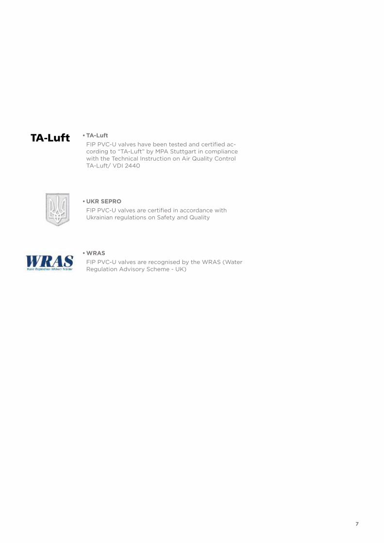
1 Ergonomic HIPVC handle equipped with removable tool to adjust the ball seat carrier.
2 Handle lock 0°- 90° SHKD (available as an accessory) ergonomically operable during service and padlockable
3 Robust integrated bracket for valve anchoring, for easy and quick automation even after valve installation on the system via the Power Quick module (optional)
4 DUAL BLOCK® patented lock system that ensures union nut tightening hold even in severe conditions such as vibrations or heat dilation
1
2
3
4

PRESSURE DROP GRAPH
Pre
ssu
re d
rop
Flow Rate
bar1 10 100 1000 10000 l/min
1
0.1
0.01
0.001
DN
15
DN
10
DN
20
DN
25
DN
32
DN
40
DN
50
18
TECHNICAL DATA
-40 -20 0 20 40 60 80 100 120 140 °C
16
14
12
10
8
6
4
2
0
Wo
rkin
g p
ress
ure
Working temperature
barPRESSURE VARIATION ACCORDING TO TEMPERATURE
For water and harmless fluids to which the material is classified as CHEMICALLY RESISTANT. In other cases, a reduction of the nominal PN pressure is required (25 years with safety factor).
KV100 FLOW COEFFICIENTThe Kv100 flow coefficient is the Q flow rate of litres per minute of water at a temperature of 20°C that will generate ∆p= 1 bar pressure drop at a certain valve position.The Kv100 values shown in the table are calculated with the valve completely open.
DN 10 15 20 25 32 40 50
Kv100 l/min 80 200 385 770 1100 1750 3400

19
The information in this leaflet is provided in good faith. No liability will be accepted concerning technical data that is not directly covered by recognised international standards. FIP reserves the right to carry out any modification. Products must be installed and maintained by qualified personnel.
OPERATING TORQUE AT MAXIMUM WORKING PRESSURE
Nm 10 15 20 25 32 40 50 DN
20
18
16
14
12
10
8
6
4
2
0
Op
erat
ing
to
rqu
e

d DN PN B B1 C C1 E H H1 L Z g EPDM Code FPM Code
16 10 16 54 29 67 40 54 103 65 14 75 215 VKDIV016E VKDIV016F
20 15 16 54 29 67 40 54 103 65 16 71 205 VKDIV020E VKDIV020F
25 20 16 65 34.5 85 49 65 115 70 19 77 330 VKDIV025E VKDIV025F
32 25 16 69.5 39 85 49 73 128 78 22 84 438 VKDIV032E VKDIV032F
40 32 16 82.5 46 108 64 86 146 88 26 94 693 VKDIV040E VKDIV040F
50 40 16 89 52 108 64 98 164 93 31 102 925 VKDIV050E VKDIV050F
63 50 16 108 62 134 76 122 199 111 38 123 1577 VKDIV063E VKDIV063F
d DN PN B B1 C C1 E H H1 L g EPDM Code FPM Code
16 10 16 54 29 67 40 54 149 65 14 215 VKDDV016E VKDDV016F
20 15 16 54 29 67 40 54 124 65 16 220 VKDDV020E VKDDV020F
25 20 16 65 34.5 85 49 65 144 70 19 340 VKDDV025E VKDDV025F
32 25 16 69.5 39 85 49 73 154 78 22 443 VKDDV032E VKDDV032F
40 32 16 82.5 46 108 64 86 174 88 26 693 VKDDV040E VKDDV040F
50 40 16 89 52 108 64 98 194 93 31 945 VKDDV050E VKDDV050F
63 50 16 108 62 134 76 122 224 111 38 1607 VKDDV063E VKDDV063F
d DN PN B B1 C C1 E H H1 L Z g EPDM Code FPM Code
16 10 16 54 29 67 40 54 103 65 14 75 225 VKDIVSHX016E VKDIVSHX016F
20 15 16 54 29 67 40 54 103 65 16 71 215 VKDIVSHX020E VKDIVSHX020F
25 20 16 65 34.5 85 49 65 115 70 19 77 340 VKDIVSHX025E VKDIVSHX025F
32 25 16 69.5 39 85 49 73 128 78 22 84 448 VKDIVSHX032E VKDIVSHX032F
40 32 16 82.5 46 108 64 86 146 88 26 94 703 VKDIVSHX040E VKDIVSHX040F
50 40 16 89 52 108 64 98 164 93 31 102 935 VKDIVSHX050E VKDIVSHX050F
63 50 16 108 62 134 76 122 199 111 38 123 1587 VKDIVSHX063E VKDIVSHX063F
VKDIV
VKDDV
DUAL BLOCK® 2-way ball valve with female ends for solvent welding, metric series
DUAL BLOCK® 2-way ball valve with male ends for solvent welding, metric series
VKDIV/SHXDUAL BLOCK® 2-way ball valve with handle lock and STAINLESS steel threaded inserts with female ends for solvent welding, metric series
20
DIMENSIONS

d DN PN B B1 C C1 E H H1 L Z g EPDM Code FPM Code
3/8” 10 16 54 29 67 40 54 103 65 14.5 74 210 VKDLV038E VKDLV038F
1/2” 15 16 54 29 67 40 54 103 65 16.5 70 205 VKDLV012E VKDLV012F
3/4” 20 16 65 34.5 85 49 65 115 70 19 77 335 VKDLV034E VKDLV034F
1” 25 16 69.5 39 85 49 73 128 78 22.5 83 433 VKDLV100E VKDLV100F
1” 1/4 32 16 82.5 46 108 64 86 146 88 26 94 703 VKDLV114E VKDLV114F
1” 1/2 40 16 89 52 108 64 98 164 93 30 104 925 VKDLV112E VKDLV112F
2” 50 16 108 62 134 76 122 199 111 36 127 1647 VKDLV200E VKDLV200F
VKDLVDUAL BLOCK® 2-way ball valve with female ends for solvent welding, BS series
R DN PN B B1 C C1 E H H1 L Z g EPDM Code FPM Code
3/8” 10 16 54 29 67 40 54 103 65 12** 80 215 VKDFV038E VKDFV038F
1/2” 15 16 54 29 67 40 54 110 65 15 80 210 VKDFV012E VKDFV012F
3/4” 20 16 65 34.5 85 49 65 116 70 16 83 335 VKDFV034E VKDFV034F
1” 25 16 69.5 39 85 49 73 134 78 19 96 448 VKDFV100E VKDFV100F
1” 1/4 32 16 82.5 46 108 64 86 153 88 21 110 678 VKDFV114E VKDFV114F
1” 1/2 40 16 89 52 108 64 98 156 93 21 113 955 VKDFV112E VKDFV112F
2” 50 16 108 62 134 76 122 186 111 26 135 1667 VKDFV200E VKDFV200F
d DN PN B B1 C C1 E H H1 L Z g EPDM Code FPM Code
3/8” 10 16 54 29 67 40 54 117 65 19.5 78 230 VKDAV038E VKDAV038F
1/2” 15 16 54 29 67 40 54 117 65 22.5 72 215 VKDAV012E VKDAV012F
3/4” 20 16 65 34.5 85 49 65 129 70 25.5 78 345 VKDAV034E VKDAV034F
1” 25 16 69.5 39 85 49 73 142 78 28.7 84.6 448 VKDAV100E VKDAV100F
1” 1/4 32 16 82.5 46 108 64 86 162 88 32 98 718 VKDAV114E VKDAV114F
1” 1/2 40 16 89 52 108 64 98 172 93 35 102 975 VKDAV112E VKDAV112F
2” 50 16 108 62 134 76 122 199 111 38.2 122.6 1712 VKDAV200E VKDAV200F
VKDFV
VKDAV
DUAL BLOCK® 2-way ball valve with BSP threaded female ends
DUAL BLOCK® 2-way ball valve with female ends for solvent welding, ASTM series
21

R DN PN B B1 C C1 E H H1 L Z g EPDM Code FPM Code
3/8” 10 16 54 29 67 40 54 103 65 13.7 75.6 215 VKDNV038E VKDNV038F
1/2” 15 16 54 29 67 40 54 111 65 17.8 75.4 210 VKDNV012E VKDNV012F
3/4” 20 16 65 34.5 85 49 65 117 70 18 81 335 VKDNV034E VKDNV034F
1” 25 16 69.5 39 85 49 73 135 78 22.6 89.8 448 VKDNV100E VKDNV100F
1” 1/4 32 16 82.5 46 108 64 86 153 88 25.1 102.8 678 VKDNV114E VKDNV114F
1” 1/2 40 16 89 52 108 64 98 156 93 24.7 106.6 955 VKDNV112E VKDNV112F
2” 50 16 108 62 134 76 122 186 111 29.6 126.8 1667 VKDNV200E VKDNV200F
d DN PN B B1 C C1 E H H1 L Z g EPDM Code FPM Code
1/2” 15 16 54 29 67 40 54 131 65 30 71 225 VKDJV012E VKDJV012F
3/4” 20 16 65 34.5 85 49 65 147 70 35 77 335 VKDJV034E VKDJV034F
1” 25 16 69.5 39 85 49 73 164 78 40 84 448 VKDJV100E VKDJV100F
1” 1/4 32 16 82.5 46 108 64 86 182 88 44 94 728 VKDJV114E VKDJV114F
1” 1/2 40 16 89 52 108 64 98 212 93 55 102 1015 VKDJV112E VKDJV112F
2” 50 16 108 62 134 76 122 248 111 63 122 1727 VKDJV200E VKDJV200F
R DN PN B B1 C C1 E H H1 L Z g EPDM Code FPM Code
1/2” 15 16 54 29 67 40 54 103 65 16 71 210 VKDGV012E VKDGV012F
3/4” 20 16 65 34.5 85 49 65 115 70 19 77 330 VKDGV034E VKDGV034F
1” 25 16 69.5 39 85 49 73 128 78 22 84 438 VKDGV100E VKDGV100F
1” 1/4 32 16 82.5 46 108 64 86 146 88 25 96 678 VKDGV114E VKDGV114F
1” 1/2 40 16 89 52 108 64 98 164 93 26 112 975 VKDGV112E VKDGV112F
2” 50 16 108 62 134 76 122 199 111 31 137 1627 VKDGV200E VKDGV200F
VKDNV
VKDJV
VKDGV
DUAL BLOCK® 2-way ball valve with female ends, NPT thread
DUAL BLOCK® 2-way ball valve with female ends for solvent welding, JIS series
DUAL BLOCK® 2-way ball valve with female ends, JIS thread
22

d DN PN B B1 C C1 F f H H1 Sp U g EPDM Code FPM Code
20 15 16 54 29 67 40 65 14 130 65 11 4 375 VKDOV020E VKDOV020F
25 20 16 65 34.5 85 49 75 14 150 70 14 4 590 VKDOV025E VKDOV025F
32 25 16 69.5 39 85 49 85 14 160 78 14 4 713 VKDOV032E VKDOV032F
40 32 16 82.5 46 108 64 100 18 180 88 14 4 1108 VKDOV040E VKDOV040F
50 40 16 89 52 108 64 110 18 200 93 16 4 1485 VKDOV050E VKDOV050F
63 50 16 108 62 134 76 125 18 230 111 16 4 2347 VKDOV063E VKDOV063F
d DN PN B B1 C C1 F f H H1 Sp U g EPDM Code FPM Code
1/2” 15 16 54 29 67 40 60.3 15.9 143 65 11 4 460 VKDOAV012E VKDOAV012F
3/4” 20 16 65 34.5 85 49 69.9 15.9 172 70 14 4 632 VKDOAV034E VKDOAV034F
1” 25 16 69.5 39 85 49 79.4 15.9 187 78 14 4 853 VKDOAV100E VKDOAV100F
1” 1/4 32 16 82.5 46 108 64 88.9 15.9 190 88 14 4 1313 VKDOAV114E VKDOAV114F
1” 1/2 40 16 89 52 108 64 98.4 15.9 212 93 16 4 1669 VKDOAV112E VKDOAV112F
2” 50 16 108 62 134 76 120.7 19.1 234 111 16 4 2577 VKDOAV200E VKDOAV200F
VKDOV
VKDOAV
DUAL BLOCK® 2-way ball valve with EN/ISO/DIN PN 10/16 fixed flanges, Face to face according to EN 558-1
DUAL BLOCK® 2-way ball valve with fixed flange, drilled ANSI B16.5 cl.150#FF
d DN PN B B1 C C1 E H H1 L Z g EPDM Code FPM Code
20 15 16 54 29 67 40 54 175 65 41 94 220 VKDBEV020E VKDBEV020F
25 20 16 65 34.5 85 49 65 210 70 52 106 340 VKDBEV025E VKDBEV025F
32 25 16 69.5 39 85 49 73 226 78 55 117 443 VKDBEV032E VKDBEV032F
40 32 16 82.5 46 108 64 86 243 88 56 131 693 VKDBEV040E VKDBEV040F
50 40 16 89 52 108 64 98 261 93 58 145 945 VKDBEV050E VKDBEV050F
63 50 16 108 62 134 76 122 293 111 66 161 1607 VKDBEV063E VKDBEV063F
VKDBEVDUAL BLOCK® 2-way ball valve with PE100 SDR 11 male end connectors for butt weld-ing or electrofusion (CVDE)
23

ACCESSORIES
d DN Code
16 - 20 10 - 15 SHKD020
25 - 32 20 - 25 SHKD032
40 - 50 32 - 40 SHKD050
63 50 SHKD063
SHKDHandle block kit 0° - 90° lockable
d DN A A1 A2 E B B1 B min Code
16 10 32 25 32 54 70 29 139.5 PSKD020
20 15 32 25 32 54 70 29 139.5 PSKD020
25 20 32 25 40 65 89 34.5 164.5 PSKD025
32 25 32 25 40 73 93.5 39 169 PSKD032
40 32 40 32 50 86 110 46 200 PSKD040
50 40 40 32 50 98 116 52 206 PSKD050
63 50 40 32 59 122 122 62 225 PSKD063
PSKDStem extension
PMKD
d DN A B C C1 C2 F f f1 S Code
16 10 30 86 20 46 67.5 6.5 5.3 5.5 5 PMKD1
20 15 30 86 20 46 67.5 6.5 5.3 5.5 5 PMKD1
25 20 30 86 20 46 67.5 6.5 5.3 5.5 5 PMKD1
32 25 30 86 20 46 67.5 6.5 5.3 5.5 5 PMKD1
40 32 40 122 30 72 102 6.5 6.3 6.5 6 PMKD2
50 40 40 122 30 72 102 6.5 6.3 6.5 6 PMKD2
63 50 40 122 30 72 102 6.5 6.3 6.5 6 PMKD2
Mounting plate
24
d DN PN L SDR Code
20 15 16 55 11 CVDE11020
25 20 16 70 11 CVDE11025
32 25 16 74 11 CVDE11032
40 32 16 78 11 CVDE11040
52 40 16 84 11 CVDE11050
63 50 16 91 11 CVDE11063
CVDELong spigot PE100 end connectors for joints with electrofusion fittings or for butt welding

POWER QUICK CPThe valve can be equipped with pneumatic actuators, using the PP-GR module repro-ducing the drilling pattern foreseen by ISO 5211
d DN B2 Q T p x j P x J Code
16 10 58 11 12 F03 x 5,5 F04 x 5,5 PQCP020
20 15 58 11 12 F03 x 5,5 F04 x 5,5 PQCP020
25 20 69 11 12 *F03 x 5,5 F05 x 6,5 PQCP025
32 25 74 11 12 *F03 x 5,5 F05 x 6,5 PQCP032
40 32 91 14 16 F05 x 6,5 F07 x 8,5 PQCP040
50 40 97 14 16 F05 x 6,5 F07 x 8,5 PQCP050
63 50 114 14 16 F05 x 6,5 F07 x 8,5 PQCP063
*F04 x 5.5 on request
POWER QUICK CEThe valve can be equipped with electric actuators, using the PP-GR module reproduc-ing the drilling pattern foreseen by ISO 5211
d DN B2 Q T p x j P x J Code
16 10 58 14 16 F03 x 5,5 F04 x 5,5 PQCE020
20 15 58 14 16 F03 x 5,5 F04 x 5,5 PQCE020
25 20 69 14 16 *F03 x 5,5 F05 x 6,5 PQCE025
32 25 74 14 16 *F03 x 5,5 F05 x 6,5 PQCE032
40 32 91 14 16 F05 x 6,5 F07 x 8,5 PQCE040
50 40 97 14 16 F05 x 6,5 F07 x 8,5 PQCE050
63 50 114 14 16 F05 x 6,5 F07 x 8,5 PQCE063
*F04 x 5.5 on request
EASYTORQUE KITKit for ball seat carrier tightening adjustment for DUAL BLOCK® DN 10÷50 series valves
d DN Tightening torque recommended* Code
3/8”-1/2” 10-15 3 N m - 2,21 Lbf ft KET01
3/4” 20 4 N m - 2,95 Lbf ft KET01
1” 25 5 N m - 3,69 Lbf ft KET01
1” 1/4 32 5 N m - 3,69 Lbf ft KET01
1” 1/2 40 7 N m - 5,16 Lbf ft KET01
2” 50 9 N m - 6,64 Lbf ft KET01
*calculated in ideal installation conditions
25
FASTENING AND SUPPORTING
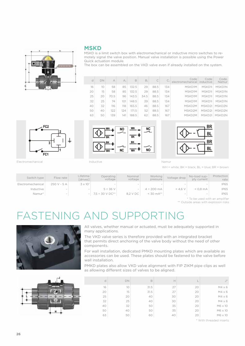
d DN B H L J*
16 10 31.5 27 20 M4 x 6
20 15 31.5 27 20 M4 x 6
25 20 40 30 20 M4 x 6
32 25 40 30 20 M4 x 6
40 32 50 35 20 M6 x 10
50 40 50 35 20 M6 x 10
63 50 60 40 20 M6 x 10
* With threaded inserts
All valves, whether manual or actuated, must be adequately supported in many applications. The VKD valve series is therefore provided with an integrated bracket that permits direct anchoring of the valve body without the need of other components.For wall installation, dedicated PMKD mounting plates which are available as accessories can be used. These plates should be fastened to the valve before wall installation. PMKD plates also allow VKD valve alignment with FIP ZIKM pipe clips as well as allowing different sizes of valves to be aligned.
Switch type Flow rate Lifetime[drives]
Operating voltage
Nominal voltage
Working pressure Voltage drop No-load sup-
ply currentProtection
rate
Electromechanical 250 V - 5 A 3 x 10⁷ - - - - - IP65
Inductive - - 5 ÷ 36 V - 4 ÷ 200 mA < 4,6 V < 0,8 mA IP65
Namur* - - 7,5 ÷ 30 V DC** 8,2 V DC < 30 mA** - - IP65
* To be used with an amplifier** Outside areas with explosion risks
Electromechanical Inductive Namur
WH = white; BK = black; BL = blue; BR = brown
MSKDMSKD is a limit switch box with electromechanical or inductive micro switches to re-motely signal the valve position. Manual valve installation is possible using the Power Quick actuation module.The box can be assembled on the VKD valve even if already installed on the system.
d DN A A1 B B1 C C1Code
electromechanicalCode
inductiveCode.
Namur
16 10 58 85 132.5 29 88.5 134 MSKD1M MSKD1I MSKD1N
20 15 58 85 132.5 29 88.5 134 MSKD1M MSKD1I MSKD1N
25 20 70.5 96 143.5 34.5 88.5 134 MSKD1M MSKD1I MSKD1N
32 25 74 101 148.5 39 88.5 134 MSKD1M MSKD1I MSKD1N
40 32 116 118 165.5 46 88.5 167 MSKD2M MSKD2I MSKD2N
50 40 122 124 171.5 52 88.5 167 MSKD2M MSKD2I MSKD2N
63 50 139 141 188.5 62 88.5 167 MSKD2M MSKD2I MSKD2N
26

COMPONENTSEXPLODED VIEW
1 Handle insert (PVC-U - 1)2 Handle (HIPVC - 1)3 Stem O-rings
(EPDM-FPM - 2)*4 Stem (PVC-U - 1)5 Ball seat
(PTFE - 2)*6 Ball (PVC-U - 1)7 Body (PVC-U - 1)8 Ball seat O-Rings (EPDM-FPM - 2)*
* Spare parts
** Accessories
The component material and quantity supplied are indicated in the parentheses.
9 Radial seal O-Ring (EPDM-FPM - 1)10 Socket seal O-Ring (EPDM-FPM - 2)11 Ball seat carrier
(PVC-U - 1)12 End connector (PVC-U - 2)13 Union nut (PVC-U - 2)14 Spring (STAINLESS steel - 1)**15 Handle safety
block (PP-GR - 1)**
16 DUAL BLOCK® (POM - 1)17 Threaded inserts
(STAINLESS steel or Brass - 2)**18 Distance plate (PP-GR - 1)**19 Screw (STAINLESS steel - 2)**
27

INSTALLATIONBefore proceeding with installation. please follow these instructions carefully:1) Check that the pipes to be connected to the valve are aligned in order to avoid
mechanical stress on the threaded joints.2) Check that the DUAL BLOCK® union nut locking device (16) is fitted to the valve
body.3) To release the union nuts, axially press the release lever to separate the lock and
then unscrew it in the counter-clockwise direction.4) Unscrew the union nuts (13) and insert them on the pipe segments.5) Solvent weld or screw the end connectors (12) onto the pipe ends.6) Position the valve body between the end connectors and fully tighten the union
nuts (13) manually by rotating clockwise without using wrenches or other tools that could damage the union nut surface.
7) Lock the union nuts by returning the DUAL BLOCK® to its housing, pressing on it until the hinges lock on the union nuts.
DISMOUNTING ASSEMBLY1) Isolate the valve from the line (re-
lease the pressure and empty the pipeline).
2) Unlock the union nuts by pressing the lever on the DUAL BLOCK® (16) along the axis and separate it from the union nut (fig. 1-2). It is also pos-sible to completely remove the block device from the body of the valve.
3) Fully unscrew the union nuts (13) and extract the body sideways.
4) Before dismounting, hold the valve in a vertical position and open it 45° to drain any liquid that might remain.
5) After closing the valve, remove the special insert (1) from the handle (2) and push the two projecting ends into the corresponding recesses on the ball seat carrier (11). Rotate the stop ring anti-clockwise to extract it (fig. 3-4).
6) Pull the handle (2) upwards to re-move it from the valve stem (4).
7) Press on the ball from the side oppo-site the “REGULAR - ADJUST” label, being sure not to scratch it, until the ball seat carrier exits (11), then ex-tract the ball (6).
8) Press the stem (4) inwards until it ex-its the body.
9) Remove the O-Ring (3, 8, 9, 10) and PTFE ball seats (5) extracting them from their grooves, as illustrated in the exploded view.
1) All the O-rings (3, 8, 9, 10) must be in-serted in their grooves as shown in the exploded view.
2) Insert the stem (4) from inside the valve body (7).
3) Place the PTFE ball seats (5) in the housings in the body (7) and in the ball seat ball seat carrier (11).
4) Insert the ball (6) rotating it to the closed position.
5) Screw the carrier (11) into the body and tighten up in the clockwise direc-tion using the handle (2) to limit stop.
6) lnsert the valve between the end con-nectors (12) and tighten the union nuts (13) making sure that the socket seal O-rings (10) do not exit their seats.
7) The handle (2) should be placed on the valve stem (4).
Note: during assembly operations, it is advisable to lubricate the rubber seals. Mineral oils are not recommended for this task as they react aggressively with EPDM rubber.
Fig. 3
Fig. 4
Fig. 2
Fig. 1
28

Fig. 5
8) If necessary, support the pipework with FIP pipe clips or by means of the carrier built into the valve itself (see paragraph “fastening and carriers”).
The VKD valve can be equipped with a handle lock to prevent ball rotation (supplied separately).When the handle safety block (14, 15) is installed, lift the lever (15) and rotate the handle (fig. 6-7).A lock can also be installed on the handle to protect the system against tampering (fig. 8).Seal can be adjusted using the extractable insert on the handle (fig. 3-4). The seals can be adjusted later with the valve installed on the pipe by simply tight-ening the union nuts. This "micro adjustment", only possible with FIP valves thanks to the patented "Seat stop system", allows the seal to be recovered where PTFE ball seats are worn due to a high number of operations.The Easytorque kit can also be used for micro adjustments (fig. 5).
WARNINGS- If volatile liquid such as Hydrogen Peroxide (H2O2) or Sodium Hypochlorite
(NaCIO) are used, for safety reasons we recommend you contact the service cen-tre. These liquids, upon vaporising, could create hazardous over pressures in the area between the body and ball.
- Always avoid sudden closing operations and protect the valve from accidental op-erations.
Fig. 8
Fig. 7
Fig. 6
29


VKD DN 65÷100PVC-U
DUAL BLOCK® 2-way ball valve

FIP has developed aVKD DUAL BLOCK®ball valve to introduce a high reference standard in thermosplastic valve design. VKD is a True Union ball valve that meets the most stringent needs required by industrial applications.This valve is alsoequipped with acustomisableLabelling System.
32
Technical specificationsConstruction 2-way True Union ball valve with locked carrier and
union nuts.Size range DN 65 ÷ 100Nominal pressure PN 16 with water at 20° CTemperature range 0 °C ÷ 60 °CCoupling standards Solvent welding: EN ISO 1452, EN ISO 15493, BS 4346-
1, DIN 8063, NF T54-028, ASTM D 2467, JIS K 6743. Pipe coupling as per EN ISO 1452, EN ISO 15493, DIN 8062, NF T54-016, ASTM D 1785, JIS K 6741
Thread: ISO 228-1, DIN2999, ASTM D 2467, JIS B 0203
Flanging system: ISO 7005-1, EN ISO 1452, EN ISO 15493, EN 588-1, DIN 2501, ANSI B.16.5 cl.150, JIS B 2220
Reference standards Construction criteria: EN ISO 16135, EN ISO 1452, EN ISO 15493Test methods and requirements: ISO 9393Installation criteria: DVS 2204, DVS 2221, UNI 11242Actuator couplings: ISO 5211
Valve material PVC-USeal material EPDM, FPM;
PTFE (ball seats)
Control options Manual control; electric actuator; pneumatic actuator
VKD
DUAL BLOCK® 2-WAY BALL VALVE
• Connection system for solvent weld, threaded and flanged joints• Patented SEAT STOP® ball carrier system that lets you micro-adjust seals
and minimise axial force effects • Easy radial dismounting allowing quick replacement of O-rings and ball
seats without any need for tools• PN16 True Union valve body made for rigid PVC-U injection moulding
equipped with built-in bores for actuation. ISO 9393 compliant test requi-sites
• Option of dismounting downstream pipes with the valve in the closed po-sition
• Full bore ball with high surface finish • Integrated bracket for valve anchoring• Possibility of installing a manual reducer or pneumatic and/or electric ac-
tuators by applying an ISO standard bore PP-GR flange• STAINLESS steel co-moulded stem, with square section as per ISO 5211
DN 65÷100

33
1 HIPVC ergonomic multifunctional handle for quick operation, lock and graduated adjustment in 10 positions. Possibility of inhibiting rotation with a lock
2 Customisable Labelling System: LCE module made of a transparent protection plug and customisable tag holder using the LSE set (available as accessory). The customisation lets you identify the valve on the system according to specific needs
3 DUAL BLOCK® patented lock system that ensures union nut tightening hold even in severe conditions such as vibrations or heat dilation
4 Double stem with double O-Rings for ball centring and operating torque reduction
1
2
3
4
4

PRESSURE DROP GRAPH
Pre
ssu
re d
rop
Flow Rate
bar1 10 100 1000 10000 l/min
1
0.1
0.01
0.001
DN
65
DN
80
DN
100
34
TECHNICAL DATA
-40 -20 0 20 40 60 80 100 120 140 °C
16
14
12
10
8
6
4
2
0
Wo
rkin
g p
ress
ure
Working temperature
barPRESSURE VARIATION ACCORDING TO TEMPERATUREFor water and harmless fluids to which the material is classified as CHEMICALLY RESISTANT. In other cases, a reduction of the nominal PN pressure is required (25 years with safety factor).
KV100 FLOW COEFFICIENTThe Kv100 flow coefficient is the Q flow rate of litres per minute of water at a temperature of 20°C that will generate ∆p= 1 bar pressure drop at a certain valve position.The Kv100 values shown in the table are calculated with the valve completely open.
DN 65 80 100
Kv100 l/min 5250 7100 9500

35
The information in this leaflet is provided in good faith. No liability will be accepted concerning technical data that is not directly covered by recognised international standards. FIP reserves the right to carry out any modification. Products must be installed and maintained by qualified personnel.
OPERATING TORQUE AT MAXIMUM WORKING PRESSURE
Nm 65 80 100 65 80 100 65 80 100 DN
70
60
50
40
30
20
10
0
Op
erat
ing
to
rqu
e
PN 6 PN 10 PN 16

d DN PN B B1 C C1 E H H1 L Z g EPDM Code FPM Code
75 65 16 164 87 225 175 164 235 133 44 147 4380 VKDIV075E VKDIV075F
90 80 16 177 105 327 272 203 270 149 51 168 7200 VKDIV090E VKDIV090F
110 100 16 195 129 385 330 238 308 167 61 186 11141 VKDIV110E VKDIV110F
d DN PN B B1 C C1 E H H1 L g EPDM Code FPM Code
75 65 16 164 87 225 175 164 284 133 44 4420 VKDDV075E VKDDV075F
90 80 16 177 105 327 272 203 300 149 51 6930 VKDDV090E VKDDV090F
110 100 16 195 129 385 330 238 340 167 61 10950 VKDDV110E VKDDV110F
VKDIV
VKDDV
DUAL BLOCK® 2-way ball valve with female ends, metric series
DUAL BLOCK® 2-way ball valve with male ends for solvent welding, metric series
d DN PN B B1 C C1 E H H1 L Z g EPDM Code FPM Code
2” 1/2 65 16 164 87 225 175 164 235 133 44 147 4380 VKDLV212E VKDLV212F
3” 80 16 177 105 327 272 203 270 149 51 168 7250 VKDLV300E VKDLV300F
4” 100 16 195 129 385 330 238 308 167 63 182 10995 VKDLV400E VKDLV400F
VKDLVDUAL BLOCK® 2-way ball valve with female ends for solvent welding, BS series
R DN PN B B1 C C1 E H H1 L Z g EPDM Code FPM Code
2” 1/2 65 16 164 87 225 175 164 235 133 30 175 4395 VKDFV212E VKDFV212F
3” 80 16 177 105 327 272 203 270 149 34 203 7260 VKDFV300E VKDFV300F
4” 100 16 195 129 385 330 238 308 167 40 229 11100 VKDFV400E VKDFV400F
VKDFVDUAL BLOCK® 2-way ball valve with BSP threaded female ends
36
DIMENSIONS

d DN PN B B1 C C1 E H H1 L Z g EPDM Code FPM Code
2” 1/2 65 16 164 87 225 175 164 235 133 44,5 146 4390 VKDAV212E VKDAV212F
3” 80 16 177 105 327 272 203 270 149 48 174 7210 VKDAV300E VKDAV300F
4” 100 16 195 129 385 330 238 308 167 57,5 193 11065 VKDAV400E VKDAV400F
VKDAVDUAL BLOCK® 2-way ball valve with female ends for solvent welding, ASTM series
R DN PN B B1 C C1 E H H1 L Z g EPDM Code FPM Code
2” 1/2 65 16 164 87 225 175 164 235 133 33,2 168,6 4395 VKDNV212E VKDNV212F
3” 80 16 177 105 327 272 203 270 149 35,5 199 7260 VKDNV300E VKDNV300F
4” 100 16 195 129 385 330 238 308 167 37,6 232,8 11100 VKDNV400E VKDNV400F
VKDNVDUAL BLOCK® 2-way ball valve with female ends, NPT thread
d DN PN B B1 C C1 E H H1 L Z g EPDM Code FPM Code
2” 1/2 65 16 164 87 225 175 164 267 133 61 145 4435 VKDJV212E VKDJV212F
3” 80 16 177 105 327 272 203 294 149 64,5 165 7250 VKDJV300E VKDJV300F
4” 100 16 195 129 385 330 238 370 167 84 202 11580 VKDJV400E VKDJV400F
VKDJVDUAL BLOCK® 2-way ball valve with female ends for solvent welding, JIS series
R DN PN B B1 C C1 E H H1 L Z g EPDM Code FPM Code
2” 1/2 65 16 164 87 225 175 164 235 133 35 165 4400 VKDGV212E VKDGV212F
3” 80 16 177 105 327 272 203 270 149 40 190 7270 VKDGV300E VKDGV300F
4” 100 16 195 129 385 330 238 308 167 45 218 11115 VKDGV400E VKDGV400F
VKDGVDUAL BLOCK® 2-way ball valve with female ends, JIS thread
37

d DN PN B B1 C C1 F f H H1 Sp U g EPDM Code FPM Code
75 65 16 164 87 225 175 145 17 290 133 21 4 6610 VKDOV075E VKDOV075F
90 80 16 177 105 327 272 160 17 310 149 21.5 8 9330 VKDOV090E VKDOV090F
110 100 16 195 129 385 330 180 17 350 167 21.5 8 13815 VKDOV110E VKDOV110F
d DN PN B B1 C C1 F f H H1 Sp U g EPDM Code FPM Code
2” 1/2 65 16 164 87 225 175 139.7 18 290 133 21 4 6610 VKDOAV075E VKDOAV075F
3” 80 16 177 105 327 272 152.4 18 310 149 21.5 8 9330 VKDOAV090E VKDOAV090F
4” 100 16 195 129 385 330 190.5 18 350 167 21.5 8 13815 VKDOAV110E VKDOAV110F
VKDOV
VKDOAV
DUAL BLOCK® 2-way ball valve with fixed flanges, drilled PN10/16. Face to face accord-ing to EN 558-1
DUAL BLOCK® 2-way ball valve with fixed flanges, drilled ANSI B.16.5 cl.150 #FF.Face to face according to EN 558-1
d DN PN B B1 C C1 E H H1 L Z g EPDM Code FPM Code
75 65 16 164 87 225 175 162 356 133 71 214 4400 VKDOV075E VKDOV075F
90 80 16 177 105 327 272 202 390 149 88 214 7100 VKDOV090E VKDOV090F
110 100 16 195 129 385 330 236 431 167 92 247 10800 VKDOV110E VKDOV110F
VKDBEVDUAL BLOCK® 2-way valve with PE100 SDR 11 male end connectors for butt welding or electrofusion (CVDE)
38

ACCESSORIES
LSECustomisation and label printing set for Easyfit handle made up of precut adhesive sheets and software for guided label creation.
d DN Code
75 65 LSE040
90 80 LSE040
110 100 LSE040
Electromechanical Inductive Namur*
* To be used with an amplifier
VKD-MSThe MS kit lets you install a limit switch valve with electromechanical or inductive micro switches on a manual VKD valve to remotely signal the valve position (open-closed). The kit can be assembled on the valve even if already installed on the system.
d DN B B1 C C1Protection
rateCode.
electromechanicalCode
inductiveCode
Namur
75 65 266 87 150 80 IP67 FKMS1M FKMS1I FKMS1N
90 80 279 105 150 80 IP67 FKMS1M FKMS1I FKMS1N
110 100 297 129 150 80 IP67 FKMS1M FKMS1I FKMS1N
d DN PN L SDR Code
75 65 16 111 11 CVDE11075
90 80 16 118 11 CVDE11090
110 100 16 132 11 CVDE11110
CVDELong spigot PE100 end connectors for joints with electrofusion fittings or for butt welding
39

ACTUATOR MOUNTING FLANGEThe valve can be equipped with pneumatic or electric standard actuators and handwheel reduces for heavy-duty operations, using the PP-GR module reproducing the drilling pattern foreseen by ISO 5211 F07.
d DN P x J T Q
75 65 F07 x 9 16 14
90 80 F07 x 9 16 14
110 100 F07 x 9 19 17
FASTENING AND SUPPORTING
d DN J f I I1 I2
75 65 M6 6.3 17.4 90 51.8
90 80 M6 8.4 21.2 112.6 63
110 100 M8 8.4 21.2 137 67
All valves, whether manual or actuated, must be adequately supported in many applications. The VKD DN 65÷100 valve series is therefore provided with an integrated bracket that permits direct anchoring on the valve body without the need of other components.Using standard threaded nuts (not included) made of stainless steel, you can anchor the valve on 4 fastening points.
The VKD DN 65÷100 valve is equipped with the customisable Labelling System.This system lets you create special labels to insert in the handle. This makes it ex-tremely easy to apply company logos, identification serial numbers or service indica-tions such as, for example, the valve function in the system, the transported fluid, but also specific information for customer service, such as the customer name or installa-tion date or location on the valves.The specific LCE module is a standard supply and is made up of a rigid transparent water-resistant PVC plug (A-C) and white tag holder (B) made of the same material, one side of which bears the FIP logo.The holder, inserted in the plug, can be removed and, once overturned, used for cus-tomisation by applying labels printed with the software supplied with the LSE set.Proceed as follows to apply the label on the valve:1) Remove the upper part of the transparent plug (A) rotating it counter-clockwise
as indicated by the "Open" label on the plug and remove it.2) Extract the tag holder from its housing on the lower part of the plug (C)3) Apply the adhesive label on the tag holder (B) to align the profiles matching the
tab position.4) Reinsert the tag holder in its housing at the bottom of the plug5) Reposition the top of the plug in the housing rotating it clockwise; this way the
label is protected against the elements.
CUSTOMISATION
A
B
C
40

COMPONENTSEXPLODED VIEW
1-1a Transparent protection plug (PVC - 1)1b Tag holder (PVC - 1)1c O-Ring (NBR - 1)2 Handle (HIPVC - 1)3 Screw (Stainless steel - 1)4 Washer (STAINLESS steel - 1)5 Ball seat
(PTFE - 2)*6 Ball (PVC-U - 1)7 Body (PVC-U - 1)
* Spare parts
** Accessories
The component material and quantity supplied are indicated in the parentheses.
8 Ball seat O-ring (EPDM-FPM - 2)*
9 Radial seal O-Ring (EPDM- FPM - 1)*
10 Socket seal O-Ring (EPDM-FPM - 2)*
11 Screw (STAINLESS steel - 2)12 End connector (PVC-U - 2)13 Union nut (PVC-U - 2)14 Washer (STAINLESS steel - 2)15 Nut (STAINLESS steel - 2)16 Ball seat carrier (PVC-U - 1)17 Threaded ring (PVC-U - 1)
18 Stems O-Ring (EPDM-FPM - 4)19 Anti-friction disk (PTFE - 2)*20 Upper stem (PVC/Stainless steel- 1)21 Lower stem (PVC-U - 1)22 Plate (PP-GR - 1)23 Protection plug (PE - 2)24 Position indicator (PA - 1)25 DUAL BLOCK® (PP-GR +
various- 1)30 Threaded inserts (Brass - 2)**31 Actuation plate (PP-GR - 1)**
41

INSTALLATIONBefore proceeding with installation. please follow these instructions carefully:1) Check that the pipes to be connected to the valve are aligned in order to avoid
mechanical stress on the threaded joints.2) Make sure the DUAL BLOCK® union nut lock system (25) is in the FREE position.3) Unscrew the union nuts (13) and insert them on the pipe segments.4) Solvent weld or screw the end connectors (12) onto the pipe ends.5) Position the valve body between the end connectors and fully tighten the union
nuts (13) clockwise with an appropriate wrench.6) Lock the union nuts rotating the button (25) clockwise (see paragraph "union nut
lock").7) If necessary, support the piping with FIP pipe clips or by means of the carrier
built into the valve itself (see paragraph “fastening and supporting”).Adjust the ball seat carriers using the supplied tool (fig. 3).The seals can be installed later with the valve installed on the pipe by simply tighten-ing the union nuts. This "micro adjustment", only possible with FIP valves thanks to the patented "Seat stop system", allows the seal to be recovered where PTFE ball seats are worn due to a high number of operations.
DISMOUNTING ASSEMBLY1) Isolate the valve from the line (re-
lease the pressure and empty the pipeline).
2) Release the union nuts by rotating the button (25) to the left, pointing the arrow on the open lock (fig. 1).
3) Unscrew the union nuts (13) and ex-tract the body (7) (fig. 2).
4) Before dismounting, hold the valve in a vertical position and open it 45° to drain any liquid that might remain.
5) Open the valve.6) Remove the protection plug on the
handle (2) and unscrew the screw (3) with the washer (4).
7) Remove the handle (2).8) Remove the screws (11) and plate
(22) from the body (7).9) Insert the two supplied wrench
protrusions in the corresponding apertures on the threaded ring (17), extracting it by rotating counter-clockwise with the ball seat carrier (16) (fig. 3).
10) Press on the ball (6), being careful not to scratch it, and remove it from the body.
11) Press the upper stem (20) inwards and extract it from the body and remove the lower stem (21). Remove the anti-friction disks (19).
12) Remove the O-Ring (8, 9, 10, 18) and PTFE ball seats (5) extracting them from their housings, as illustrated in the exploded view.
1) All the O-rings (8, 9, 10, 18) must be inserted in their grooves as shown in the exploded view.
2) Place the anti-friction disks (19) on the stems (20-21) and insert the stems in their housings in the body.
3) Place the PTFE ball seats (5) in the housings in the valve body (7) and in the carrier (16).
4) Insert the ball (6) rotating it to the closed position.
5) Insert the carrier with threaded ring (17) into the body and tighten up in the clockwise direction using the sup-plied tool, to limit stop.
6) Position the plate (22) with rack on the body, and screw in the screws (11) washers (14) and nuts (15).
7) The handle (2) with protection plug (1, 1a, 1b, 1c) should be placed on the stem (20) (fig. 4).
8) Screw in the screw (3) with the wash-er (4) and position the protection plug (1, 1a, 1b, 1c).
9) Insert the valve between the end con-nectors (12) and tighten the union nuts (13), making sure that the socket seal O-rings (10) do not exit their seats.
10) Release the union nuts by rotating the button (25) to the right, pointing the arrow on the closed lock (fig. 1).
Note: during assembly operations, it is advisable to lubricate the rubber seals. Mineral oils are not recommended for this task as they react aggressively with EPDM rubber.
Fig. 3
Fig. 4
Fig. 2
Fig. 1
42

WARNINGS- If volatile liquid such as Hydrogen Peroxide (H2O2) or Sodium Hypochlorite
(NaCIO) are used, for safety reasons we recommend you contact the service cen-tre. These liquids, upon vaporising, could create hazardous over pressures in the area between the body and ball.
- Always avoid sudden closing operations and protect the valve from accidental op-erations.
UNION NUT LOCK
HANDLE LOCK
Rotate the button to the left, pointing the arrow on the open lock to unlock DUAL BLOCK®: the valve union nuts are free to rotate clockwise and counter-clockwise.Rotate the button to the right, pointing the arrow on the closed lock to lock DUAL BLOCK®: the valve union nuts are blocked in the desired position.
Thanks to the multifunctional handle and the red manoeuvre button on the lever, you can perform a 0°-90° operation and a graduated operation by means of the 10 inter-mediate positions and a stop lock: the handle can be locked in each of the 10 positions by simply pressing the Free-lock button. A lock can also be installed on the handle to protect the system against tampering.
The valve is two-way and can be installed in any position. It can also be installed at end line or tank.
FREE
LOCK
FREE LOCK
43

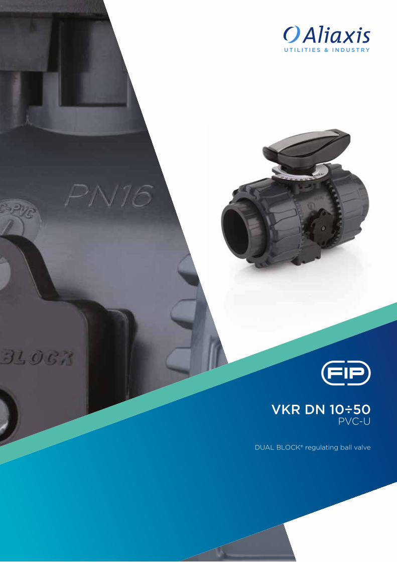
VKR DN 10÷50PVC-U
DUAL BLOCK® regulating ball valve

46
Technical specificationsConstruction 2-way True Union adjusting ball valve with locked
carrier and union nuts.Size range DN 10 ÷ 50Nominal pressure PN 16 with water at 20 °CTemperature range 0 °C ÷ 60 °CCoupling standards Solvent welding: EN ISO 1452, EN ISO 15493, BS
4346-1, DIN 8063, NF T54-028, ASTM D 2467, JIS K 6743. Pipe coupling as per EN ISO 1452, EN ISO 15493, DIN 8062, NF T54-016, ASTM D 1785, JIS K 6741
Thread: ISO 228-1, DIN 2999, ASTM D 2464, JIS B 0203
Flanging system: ISO 7005-1, EN ISO 1452, EN ISO 15493, EN 558-1, DIN 2501, ANSI B.16.5 cl. 150, JIS B 2220
Reference standards Construction criteria: EN ISO 16135, EN ISO 1452, EN ISO 15493Test methods and requirements: ISO 9393Installation criteria: DVS 2204, DVS 2221, UNI 11242Actuator couplings: ISO 5211
Valve material PVC-USeal material EPDM, FPM (standard size O-Ring);
PTFE (ball seats)
Control options Manual control; electric actuator
VKR
The VKR DUALBLOCK® valve combines high reliability and safety aspects typical ofVKD full bore ball valves with the new flow adjustment function with typical linear curve that meets the most stringent needs typical ofindustrial applications.
DUAL BLOCK® REGULATING BALL VALVE
• Connection system for solvent weld, threaded and flanged joints• Patented SEAT STOP® ball carrier system that lets you micro-adjust seals
and minimise the axial force effect • Easy radial dismounting allowing quick replacement of O-rings and ball
seats without any need for tools • PN16 True Union valve body made for rigid PVC-U injection moulding
equipped with built-in bores for actuation. ISO 9393 compliant test requi-sites
• Option of dismounting downstream pipes with the valve in the closed po-sition
• High surface finish stem with double O-Ring and double connection key to ball
• Integrated bracket for valve anchoring• Ball seat carrier can be adjusted using the Easytorque adjustment kit• Actuation option: version with electric modulating actuator with 4-20 mA
/ 0-10 V inlet and 4-20 mA / 0-10 V outlet to monitor the position • Valve suitable for carrying fluids that are clean and free of suspended
particles
DN 10÷50

1
2
5
3
4
47
1 HIPVC ergonomic multifunctional handle with position indicator and tool to adjust the ball seat carrier
2 Flow direction indication plate and opening angle with graduated scale with 5° detail for clear and accurate readings
3 90° operating angle that permits the use of standard quarter turn actuators
4 The patented ball design provides linear flow adjustment throughout its range of operation even when the valve is open just a few degrees and guarantees minimum pressure drops
5 Patented DUAL BLOCK® system: prevents union nuts from loosening even under extreme operating conditions: e.g. vibration or thermal expansion

48
TECHNICAL DATA
DN 10 15 20 25 32 40 50
Kv100 l/min 83 88 135 256 478 592 1068
KV100 FLOW COEFFICIENTThe Kv100 flow coefficient is the Q flow rate of litres per minute of water at a temperature of 20°C that will generate ∆p= 1 bar pressure drop at a certain valve position.The Kv100 values shown in the table are calculated with the valve completely open.
-40 -20 0 20 40 60 80 100 120 140 °C
16
14
12
10
8
6
4
2
0
Wo
rkin
g p
ress
ure
Working temperature
barPRESSURE VARIATION ACCORDING TO TEMPERATURE
For water and harmless fluids to which the material is classified as CHEMICALLY RESISTANT. In other cases, a reduction of the nominal PN pressure is required (25 years with safety factor).
PRESSURE DROP GRAPH
Pre
ssu
re d
rop
Flow Rate
bar1 10 100 1000 10000 l/min
1
0.1
0.01
0.001
DN
15
DN
10D
N 2
0D
N 2
5D
N 3
2D
N 4
0D
N 5
0

49
The information in this leaflet is provided in good faith. No liability will be accepted concerning technical data that is not directly covered by recognised international standards. FIP reserves the right to carry out any modification. Products must be installed and maintained by qualified personnel.
OPERATING TORQUE AT MAXIMUM WORKING PRESSURE
Nm 10 15 20 25 32 40 50 DN
20
18
16
14
12
10
8
6
4
2
0
Op
erat
ing
to
rqu
e
RELATIVE FLOW COEFFICIENT DIAGRAM
5 10 15 20 25 30 35 40 45 50 55 60 65 70 75 80 85 90 °
100
90
80
70
60
50
40
30
20
10
0
Rel
ativ
e fl
ow
co
effici
ent
Ball aperture angle
%
The relative flow coefficient is the flow rate through the valve as a function of the degree of valve aperture.

d DN PN B B1 C C1 E H H1 L Z g EPDM Code FPM Code
16 10 16 54 29 67 40 54 103 65 14 75 215 VKRIV016E VKRIV016F
20 15 16 54 29 67 40 54 103 65 16 71 205 VKRIV020E VKRIV020F
25 20 16 65 34.5 85 49 65 115 70 19 77 330 VKRIV025E VKRIV025F
32 25 16 69.5 39 85 49 73 128 78 22 84 438 VKRIV032E VKRIV032F
40 32 16 82.5 46 108 64 86 146 88 26 94 693 VKRIV040E VKRIV040F
50 40 16 89 52 108 64 98 164 93 31 102 925 VKRIV050E VKRIV050F
63 50 16 108 62 134 76 122 199 111 38 123 1577 VKRIV063E VKRIV063F
d DN PN B B1 C C1 E H H1 L Z g EPDM Code FPM Code
3/8” 10 16 54 29 67 40 54 103 65 14.5 74 210 VKRLV038E VKRLV038F
1/2” 15 16 54 29 67 40 54 103 65 16.5 70 205 VKRLV012E VKRLV012F
3/4” 20 16 65 34.5 85 49 65 115 70 19 77 335 VKRLV034E VKRLV034F
1” 25 16 69.5 39 85 49 73 128 78 22.5 83 433 VKRLV100E VKRLV100F
1” 1/4 32 16 82.5 46 108 64 86 146 88 26 94 703 VKRLV114E VKRLV114F
1” 1/2 40 16 89 52 108 64 98 164 93 30 104 925 VKRLV112E VKRLV112F
2” 50 16 108 62 134 76 122 199 111 36 127 1647 VKRLV200E VKRLV200F
d DN PN B B1 C C1 E H H1 L g EPDM Code FPM Code
16 10 16 54 29 67 40 54 149 65 14 215 VKRDV016E VKRDV016F
20 15 16 54 29 67 40 54 124 65 16 220 VKRDV020E VKRDV020F
25 20 16 65 34.5 85 49 65 144 70 19 340 VKRDV025E VKRDV025F
32 25 16 69.5 39 85 49 73 154 78 22 443 VKRDV032E VKRDV032F
40 32 16 82.5 46 108 64 86 174 88 26 693 VKRDV040E VKRDV040F
50 40 16 89 52 108 64 98 194 93 31 945 VKRDV050E VKRDV050F
63 50 16 108 62 134 76 122 224 111 38 1607 VKRDV063E VKRDV063F
VKRIVDUAL BLOCK® regulating ball valve with female ends for solvent welding, metric series
DUAL BLOCK® regulating ball valve with male ends for solvent welding, metric series
VKRDV
DUAL BLOCK® regulating ball valve with female ends for solvent welding, ASTM se-ries
VKRLV
50
DIMENSIONS

R DN PN B B1 C C1 E H H1 L Z g EPDM Code FPM Code
3/8” 10 16 54 29 67 40 54 103 65 12 80 215 VKRFV038E VKRFV038F
1/2” 15 16 54 29 67 40 54 110 65 15 80 210 VKRFV012E VKRFV012F
3/4” 20 16 65 34.5 85 49 65 116 70 16 83 335 VKRFV034E VKRFV034F
1” 25 16 69.5 39 85 49 73 134 78 19 96 448 VKRFV100E VKRFV100F
1” 1/4 32 16 82.5 46 108 64 86 153 88 21 110 678 VKRFV114E VKRFV114F
1” 1/ 40 16 89 52 108 64 98 156 93 21 113 955 VKRFV112E VKRFV112F
2” 50 16 108 62 134 76 122 186 111 26 135 1667 VKRFV200E VKRFV200F
DUAL BLOCK® regulating ball valve with BSP threaded female endsVKRFV
DUAL BLOCK® regulating ball valve with female ends for solvent welding, ASTM series
DUAL BLOCK® regulating ball valve with female ends, NPT thread
VKRAV
VKRNV
d DN PN B B1 C C1 E H H1 L Z g EPDM Code FPM Code
3/8” 10 16 54 29 67 40 54 117 65 19.5 78 230 VKRAV038E VKRAV038F
1/2” 15 16 54 29 67 40 54 117 65 22.5 72 215 VKRAV012E VKRAV012F
3/4” 20 16 65 34.5 85 49 65 129 70 25.5 78 345 VKRAV034E VKRAV034F
1” 25 16 69.5 39 85 49 73 142 78 28.7 84.6 448 VKRAV100E VKRAV100F
1” 1/4 32 16 82.5 46 108 64 86 162 88 32 98 718 VKRAV114E VKRAV114F
1” 1/2 40 16 89 52 108 64 98 172 93 35 102 975 VKRAV112E VKRAV112F
2” 50 16 108 62 134 76 122 199 111 38.2 122.6 1712 VKRAV200E VKRAV200F
R DN PN B B1 C C1 E H H1 L Z g EPDM Code FPM Code
3/8” 10 16 54 29 67 40 54 103 65 13.7 75.6 215 VKRNV038E VKRNV038F
1/2” 15 16 54 29 67 40 54 111 65 17.8 75.4 210 VKRNV012E VKRNV012F
3/4” 20 16 65 34.5 85 49 65 117 70 18 81 335 VKRNV034E VKRNV034F
1” 25 16 69.5 39 85 49 73 135 78 22.6 89.8 448 VKRNV100E VKRNV100F
1” 1/4 32 16 82.5 46 108 64 86 153 88 25.1 102.8 678 VKRNV114E VKRNV114F
1” 1/2 40 16 89 52 108 64 98 156 93 24.7 106.6 955 VKRNV112E VKRNV112F
2” 50 16 108 62 134 76 122 186 111 29.6 126.8 1667 VKRNV200E VKRNV200F
51

d DN PN B B1 C C1 E H H1 L Z g EPDM Code FPM Code
1/2” 15 16 54 29 67 40 54 131 65 30 71 225 VKRJV012E VKRJV012F
3/4” 20 16 65 34.5 85 49 65 147 70 35 77 335 VKRJV034E VKRJV034F
1” 25 16 69.5 39 85 49 73 164 78 40 84 448 VKRJV100E VKRJV100F
1” 1/4 32 16 82.5 46 108 64 86 182 88 44 94 728 VKRJV114E VKRJV114F
1” 1/2 40 16 89 52 108 64 98 212 93 55 102 1015 VKRJV112E VKRJV112F
2” 50 16 108 62 134 76 122 248 111 63 122 1727 VKRJV200E VKRJV200F
R DN PN B B1 C C1 E H H1 L Z g EPDM Code FPM Code
1/2” 15 16 54 29 67 40 54 103 65 16 71 210 VKRGV012E VKRGV012F
3/4” 20 16 65 34.5 85 49 65 115 70 19 77 330 VKRGV034E VKRGV034F
1” 25 16 69.5 39 85 49 73 128 78 22 84 438 VKRGV100E VKRGV100F
1” 1/4 32 16 82.5 46 108 64 86 146 88 25 96 678 VKRGV114E VKRGV114F
1” 1/2 40 16 89 52 108 64 98 164 93 26 112 975 VKRGV112E VKRGV112F
2” 50 16 108 62 134 76 122 199 111 31 137 1627 VKRGV200E VKRGV200F
d DN PN B B1 C C1 F H H1 U f Sp g EPDM Code FPM Code
20 15 16 54 29 67 40 65 130 65 4 14 11 375 VKROV020E VKROV020F
25 20 16 65 34.5 85 49 75 150 70 4 14 14 590 VKROV025E VKROV025F
32 25 16 69.5 39 85 49 85 160 78 4 14 14 713 VKROV032E VKROV032F
40 32 16 82.5 46 108 64 100 180 88 4 18 14 1108 VKROV040E VKROV040F
50 40 16 89 52 108 64 110 200 93 4 18 16 1485 VKROV050E VKROV050F
63 50 16 108 62 134 76 125 230 111 4 18 16 2347 VKROV063E VKROV063F
DUAL BLOCK® regulating ball valve with female ends for solvent welding, JIS series
DUAL BLOCK® regulating ball valve with female ends, JIS thread
DUAL BLOCK® regulating ball valve with EN/ISO/DIN fixed flange, drilled PN10/16. Face to face according to EN 558-1
VKRJV
VKRGV
VKROV
52

ACCESSORIES
d DN PN B B1 C C1 E H H1 L Z g EPDM Code FPM Code
20 15 16 54 29 67 40 54 175 65 41 94 220 VKRBEV020E VKRBEV020F
25 20 16 65 34.5 85 49 65 210 70 52 106 340 VKRBEV025E VKRBEV025F
32 25 16 69.5 39 85 49 73 226 78 55 117 443 VKRBEV032E VKRBEV032F
40 32 16 82.5 46 108 64 86 243 88 56 131 693 VKRBEV040E VKRBEV040F
50 40 16 89 52 108 64 98 261 93 58 145 945 VKRBEV050E VKRBEV050F
63 50 16 108 62 134 76 122 293 111 66 161 1607 VKRBEV063E VKRBEV063F
d DN PN B B1 C C1 F H H1 U f Sp g EPDM Code FPM Code
1/2” 15 16 54 29 67 40 60.3 143 65 4 15.9 11 460 VKROAV012E VKROAV012F
3/4” 20 16 65 34.5 85 49 69.9 172 70 4 15.9 14 632 VKROAV034E VKROAV034F
1” 25 16 69.5 39 85 49 79.4 187 78 4 15.9 14 853 VKROAV100E VKROAV100F
1” 1/4 32 16 82.5 46 108 64 88.9 190 88 4 15.9 14 1313 VKROAV114E VKROAV114F
1” 1/2 40 16 89 52 108 64 98.4 212 93 4 15.9 16 1669 VKROAV112E VKROAV112F
2” 50 16 108 62 134 76 120.7 234 111 4 19.1 16 2577 VKROAV200E VKROAV200F
Dual Block® regulating ball valve with PE100 SDR 11 male end connectors for butt welding or electrofusion (CVDE)
DUAL BLOCK® regulating ball valve with ANSI B16.5 cl.150#FF fixed flange
VKRBEV
VKROAV
d DN PN L SDR Code
20 15 16 55 11 CVDE11020
25 20 16 70 11 CVDE11025
32 25 16 74 11 CVDE11032
40 32 16 78 11 CVDE11040
52 40 16 84 11 CVDE11050
63 50 16 91 11 CVDE11063
CVDELong spigot PE100 end connectors for joints with electrofusion fittings or for butt welding
53

All valves, whether manual or driven, must be adequately supported in many applications. The VKR valve series is therefore provided with an integrated bracket that permits direct anchoring of the valve body without the need of other components.For wall installation, dedicated PMKD mounting plates which are available as accessories can be used. These plates should be fastened to the valve before wall installation. PMKD plates also allow VKD valve alignment with FIP ZIKM pipe clips as well as allowing different sizes of valves to be aligned.
PMKD
d DN A B C C1 C2 F f f1 S Code
16 10 30 86 20 46 67.5 6.5 5.3 5.5 5 PMKD1
20 15 30 86 20 46 67.5 6.5 5.3 5.5 5 PMKD1
25 20 30 86 20 46 67.5 6.5 5.3 5.5 5 PMKD1
32 25 30 86 20 46 67.5 6.5 5.3 5.5 5 PMKD1
40 32 40 122 30 72 102 6.5 5.3 5.5 5 PMKD2
50 40 40 122 30 72 102 6.5 5.3 5.5 5 PMKD2
63 50 40 122 30 72 102 6.5 5.3 5.5 5 PMKD2
Mounting plate
FASTENING AND SUPPORTING
d DN B H L J*
16 10 31.5 27 20 M4 x 6
20 15 31.5 27 20 M4 x 6
25 20 40 30 20 M4 x 6
32 25 40 30 20 M4 x 6
40 32 50 35 20 M6 x 10
50 40 50 35 20 M6 x 10
63 50 60 40 20 M6 x 10
* With threaded inserts
EASYTORQUE KITKit for ball seat carrier tightening adjustment for DUAL BLOCK® DN 10÷50 series valves
d DN Tightening torque recommended* Code
3/8”-1/2” 10-15 3 N m - 2,21 Lbf ft KET01
3/4” 20 4 N m - 2,95 Lbf ft KET01
1” 25 5 N m - 3,69 Lbf ft KET01
1” 1/4 32 5 N m - 3,69 Lbf ft KET01
1” 1/2 40 7 N m - 5,16 Lbf ft KET01
2” 50 9 N m - 6,64 Lbf ft KET01
*calculated in ideal installation conditions
54

COMPONENTSEXPLODED VIEW
1 Handle insert (PVC-U - 1)2 Handle (HIPVC - 1)3 Stem O-ring
(EPDM-FPM - 2)*4 Stem (PVC-U - 1)5 Ball seat (PTFE - 2)*6 Patented ball design (PVC-U - 1)7 Body (PVC-U - 1)8 Ball seat O-ring
(EPDM-FPM - 2)*
* Spare parts
** Accessories
The component material and quantity supplied are indicated in the parentheses.
9 Radial seal O-Ring (EPDM, FPM - 1)
10 Socket seal O-Ring (EPDM, FPM - 2)
11 Ball seat carrier (PVC-U - 1)
12 End connector (PVC-U - 2)13 Union nut (PVC-U - 2)16 DUAL BLOCK® (POM - 1)17 Threaded inserts (STAINLESS steel or Brass - 2)**
18 Distance plate (PP-GR - 1)**19 Screw (STAINLESS steel - 2)**28 Graduated plate (POM-PVC - 1)29 Indicator (PVC - 1)
55

INSTALLATIONBefore proceeding with installation. please follow these instructions carefully:1) Check that the pipes to be connected to the valve are aligned in order to avoid
mechanical stress on the threaded joints.2) Check that the DUAL BLOCK® union nut locking device (16) is fitted to the valve
body.3) To release the union nuts (13), axially press the release lever to separate the lock
and then unscrew it in the counter-clockwise direction.4) Unscrew the union nuts (13) and insert them on the pipe segments.5) Solvent weld or screw the end connectors (12) onto the pipe ends.6) Position the valve between the pipe end connectors making sure the that direc-
tion of flow is the same as shown on the plate (Fig.4). Hand tighten the union nuts in the clockwise direction. Do not use a wrench or other tools which might damage the surface.
7) Lock the union nuts by returning the DUAL BLOCK® to its housing, pressing on it until the hinges lock on the nuts.
Fig. 3
DISMOUNTING ASSEMBLY
Fig. 4
1) Isolate the valve from the line (re-lease the pressure and empty the pipeline).
2) Unlock the union nuts by pressing the lever on the DUAL BLOCK® (16) along the axis and separate it from the union nut (fig. 1). It is also pos-sible to completely remove the block device from the body of the valve.
3) Fully unscrew the union nuts (13) and extract the body sideways.
4) Before dismounting, hold the valve in a vertical position and open it 45° to drain any liquid that might remain.
5) After closing the valve, remove the special insert (1) from the handle (2) and push the two projecting ends into the corresponding recesses on the ball seat carrier (11). Rotate the stop ring anti-clockwise to extract it.
6) Pull the handle (2) upwards to re-move it from the valve stem (4).
7) Make sure that the position indicator (29) remains properly fastened to the handle (2).
8) Press on the ball from the side oppo-site the "REGULAR - ADJUST" label, being sure not to scratch it, until the ball seat carrier exits (11), then ex-tract the ball (6).
9) Press the stem (4) inwards until it exits the valve body.
10) All the O-rings (3, 8, 9, 10) and PTFE ball seats (5) must be removed from their grooves, as shown in the ex-ploded view.
1) All the O-rings (3, 8, 9, 10) must be in-serted in their grooves as shown in the exploded view.
2) Insert the stem (4) from inside the body (7).
3) Place the PTFE ball seats (5) in the housings in the body (7) and in the ball seat carrier (11).
4) lnsert the ball (6) in the body as shown in Fig. 3
5) Screw the carrier (11) into the body and tighten up in the clockwise direction using the special insert (1) to limit stop.
6) Position the indicator (29) on the han-dle with the pointer set to 0 on the graduated scale while making sure that the valve is in the closed position (fig. 2-3).
7) Insert the handle (2) with the insert (1) in its housing on the stem (4).
8) lnsert the valve between the end con-nectors (12) making sure that they match the direction of flow shown on the plate (fig. 2) then tighten the union nuts (13) making sure that the socket seal O-rings (10) do not come out of their grooves.
Note: during assembly operations, it is advisable to lubricate the rubber seals. Mineral oils are not recommended for this task as they react aggressively with EPDM rubber.
Fig. 2
Fig. 1
56

8) If necessary, support the pipework with FIP pipe clips or by means of the carrier built into the valve itself (see paragraph “fastening and supporting”).
Seals can be adjusted using the removable insert on the handle. The seals can be installed later with the valve installed on the pipe by simply tighten-ing the union nuts. This "micro adjustment", only possible with FIP valves thanks to the patented "Seat stop system", allows the seal to be recovered where PTFE ball seats are worn due to a high number of operations. The Easytorque kit can also be used for micro adjustments (fig. 5).
Fig. 5
WARNINGS- Always avoid sudden closing operations and protect the valve from accidental op-
erations.
57


TKD DN 10÷50PVC-U
DUAL BLOCK® 3-way ball valve

60
Technical specificationsConstruction 3-way True Union ball valve with locked carrier and
union nutsSize range DN 10 ÷ 50Nominal pressure PN 16 with water at 20 °CTemperature range 0 °C ÷ 60 °CCoupling standards Solvent welding: EN ISO 1452, EN ISO 15493, BS 4346-1,
DIN 8063, NF T54-028, ASTM D 2467, JIS K 6743. Pipe coupling capacity according to EN ISO 1452, EN ISO 15493, DIN 8062, NF T54-016, ASTM D 1785, JIS K 6741
Thread: ISO 228-1, DIN 2999, ASTM D 2467, JIS B 0203.
Flanging system: ISO 7005-1, EN ISO 1452, EN ISO 15493, DIN 2501, ANSI B16.5 cl.150, JIS B 2220.
Reference standards Construction criteria: EN ISO 16135, EN ISO 1452, EN ISO 15493Test methods and requirements: ISO 9393Installation criteria: DVS 2204, DVS 2221, UNI 11242Actuator couplings: ISO 5211
Valve material PVC-USeal material EPDM, FPM (standard size O-Ring);
PTFE (ball seats)
Control options Manual control; electric actuator; pneumatic actuator
TKD
FIP has developed aTKD DUAL BLOCK®ball valve to introduce a high referencestandard in thermosplastic valve design. TKD is a True Union diverting and mixing ball valve that meets the most stringent needs required inindustrial applications.
DUAL BLOCK® 3-WAY BALL VALVE
• Connection system for solvent weld, threaded and flanged joints• Patented SEAT STOP® ball carrier system that lets you micro-adjust ball
seats and minimise axial force effects• Easy radial dismounting allowing quick replacement of O-rings and ball
seats without any need for tools• PN16 True Union valve body made for rigid PVC-U injection moulding
equipped with built-in bores for actuation. ISO 9393 compliant test requi-sites
• Option of dismounting downstream pipes with the valve in the closed position
• High surface finish stem with double O-Ring and double connection key to the ball, equipped with visual ball position indicator for correct handle installation
• Integrated bracket for valve anchoring• Possibility of installing pneumatic and/or electric actuators thanks to the
robust anchor tower for easy and quick automation using the Power Quick module (optional)
DN 10÷50

1
4
2
3
5
61
1 Ergonomic HIPVC handle equipped with removable tool to adjust the ball seat carrier. Possibility of installing the LTKD stroke limiter (available as an accessory) that permits ball and handle rotation only for set opening and closing angles at 90° or 180°
2 Handle lock 0°- 90° SHKD (available as an accessory) ergonomically operable during service and padlockable
3 DUAL BLOCK® patented lock system that ensures union nut tightening hold even in severe conditions such as vibrations or heat dilation
4 Ball shutter high surface finish with floating type full passage with T or L port
5 4 PTFE ball seat system that compensates axial force guaranteeing optimal manageability and long working life

62
bar1 10 100 1000 10000 l/min
1
0,1
0,01
0,001
DN
10
DN
20
DN
15
DN
25
DN
32
DN
40
DN
50
bar1 10 100 1000 10000 l/min
1
0,1
0,01
0,001
DN
10D
N 15
DN
20
DN
25
DN
32
DN
40
DN
50
TECHNICAL DATA
Wo
rkin
g p
ress
ure
Working temperature
PRESSURE VARIATION ACCORDING TO TEMPERATURE
For water and harmless fluids to which the material is classified as CHEMICALLY RESISTANT. In other cases, a reduction of the nominal PN pressure is required (25 years with safety factor).
PRESSURE DROP GRAPH AND WORK POSITIONS
Pre
ssu
re d
rop
Flow Rate
A - T-port ball valve:0°- Mixing
Pre
ssu
re d
rop
Flow Rate
B - T-port ball valve:90° - Diverting
-40 -20 0 20 40 60 80 100 120 140 °C
16
14
12
10
8
6
4
2
0
bar

63
bar1 10 100 1000 10000 l/min
1
0,1
0,01
0,001
DN
15
DN
10
DN
20
DN
25
DN
32
DN
40
DN
50
bar1 10 100 1000 10000 l/min
1
0,1
0,01
0,001
DN
15
DN
10
DN
20
DN
25
DN
32
DN
40
DN
50
bar1 10 100 1000 10000 l/min
1
0,1
0,01
0,001
DN
15
DN
10
DN
20
DN
25
DN
32
DN
40
DN
50
Pre
ssu
re d
rop
Flow Rate
C - T-port ball valve:180° - Branch closed/direct flow
Pre
ssu
re d
rop
Flow Rate
D - T-port ball valve:270° - Diverting
Pre
ssu
re d
rop
Flow Rate
E - L-port ball valve:0°/270° - Diverting
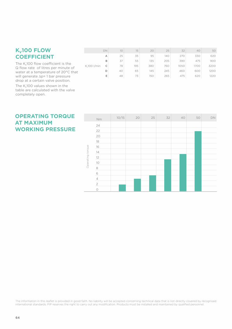
64
KV100 FLOW COEFFICIENTThe Kv100 flow coefficient is the Q flow rate of litres per minute of water at a temperature of 20°C that will generate ∆p= 1 bar pressure drop at a certain valve position.The Kv100 values shown in the table are calculated with the valve completely open.
OPERATING TORQUE AT MAXIMUM WORKING PRESSURE
Op
erat
ing
to
rqu
e
The information in this leaflet is provided in good faith. No liability will be accepted concerning technical data that is not directly covered by recognised international standards. FIP reserves the right to carry out any modification. Products must be installed and maintained by qualified personnel.
DN 10 15 20 25 32 40 50
Kv100 l/min
A 25 35 95 140 270 330 620
B 37 55 135 205 390 475 900
C 78 195 380 760 1050 1700 3200
D 40 65 145 245 460 600 1200
E 48 73 150 265 475 620 1220
Nm 10/15 20 25 32 40 50 DN
24
22
20
18
16
14
12
10
8
6
4
2
0
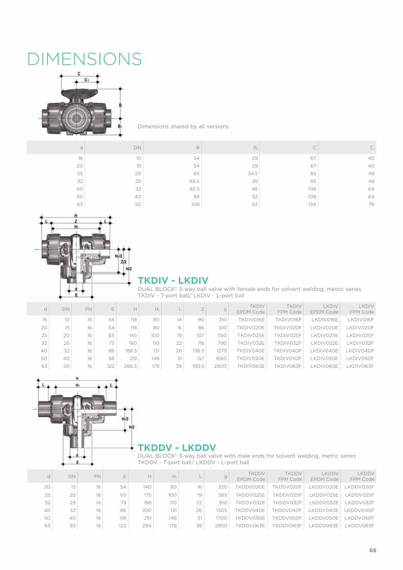
d DN PN E H H1 L Z g TKDIVEPDM Code
TKDIVFPM Code
LKDIVEPDM Code
LKDIVFPM Code
16 10 16 54 118 80 14 90 310 TKDIV016E TKDIV016F LKDIV016E LKDIV016F
20 15 16 54 118 80 16 86 310 TKDIV020E TKDIV020F LKDIV020E LKDIV020F
25 20 16 65 145 100 19 107 550 TKDIV025E TKDIV025F LKDIV025E LKDIV025F
32 25 16 73 160 110 22 116 790 TKDIV032E TKDIV032F LKDIV032E LKDIV032F
40 32 16 86 188.5 131 26 136.5 1275 TKDIV040E TKDIV040F LKDIV040E LKDIV040F
50 40 16 98 219 148 31 157 1660 TKDIV050E TKDIV050F LKDIV050E LKDIV050F
63 50 16 122 266.5 179 38 190.5 2800 TKDIV063E TKDIV063F LKDIV063E LKDIV063F
TKDIV - LKDIV
Dimensions shared by all versions
d DN PN E H H1 L g TKDDVEPDM Code
TKDDVFPM Code
LKDDVEPDM Code
LKDDVFPM Code
20 15 16 54 140 80 16 320 TKDDV020E TKDDV020F LKDDV020E LKDDV020F
25 20 16 65 175 100 19 565 TKDDV025E TKDDV025F LKDDV025E LKDDV025F
32 25 16 73 188 110 22 810 TKDDV032E TKDDV032F LKDDV032E LKDDV032F
40 32 16 86 220 131 26 1305 TKDDV040E TKDDV040F LKDDV040E LKDDV040F
50 40 16 98 251 148 31 1700 TKDDV050E TKDDV050F LKDDV050E LKDDV050F
63 50 16 122 294 179 38 2850 TKDDV063E TKDDV063F LKDDV063E LKDDV063F
TKDDV - LKDDVDUAL BLOCK® 3-way ball valve with male ends for solvent welding, metric seriesTKDDV - T-port ball/ LKDDV - L-port ball
DUAL BLOCK® 3-way ball valve with female ends for solvent welding, metric seriesTKDIV - T-port ball/ LKDIV - L-port ball
65
DIMENSIONS
d DN B B1 C C1
16 10 54 29 67 40
20 15 54 29 67 40
25 20 65 34.5 85 49
32 25 69.5 39 85 49
40 32 82.5 46 108 64
50 40 89 52 108 64
63 50 108 62 134 76

TKDLV - LKDLVDUAL BLOCK® 3-way ball valve with female ends for solvent welding, BS seriesTKDLV - T-port ball/ LKDLV - L-port ball
d DN PN E H H1 L Z g TKDLVEPDM Code
TKDLVFPM Code
LKDLVEPDM Code
LKDLVFPM Code
3/8” 10 16 54 118 80 14.7 88.6 310 TKDLV038E TKDLV038F LKDLV038E LKDLV038F
1/2” 15 16 54 118 80 17 85 310 TKDLV012E TKDLV012F LKDLV012E LKDLV012F
3/4” 20 16 65 144.8 100 19 106.8 550 TKDLV034E TKDLV034F LKDLV034E LKDLV034F
1” 25 16 73 160 110 22.5 115 790 TKDLV100E TKDLV100F LKDLV100E LKDLV100F
1” 1/4 32 16 86 188.6 131 26 136.6 1275 TKDLV114E TKDLV114F LKDLV114E LKDLV114F
1” 1/2 40 16 98 219.4 148 30.2 159 1660 TKDLV112E TKDLV112F LKDLV112E LKDLV112F
2” 50 16 122 266.6 179 36.2 194.2 2800 TKDLV200E TKDLV200F LKDLV200E LKDLV200F
TKDFV - LKDFVDUAL BLOCK® 3-way ball valve with BSP threaded female endsTKDFV - T-port ball/ LKDFV - L-port ball
R DN PN E H H1 L Z g TKDFVEPDM Code
TKDFVFPM Code
LKDFVEPDM Code
LKDFVFPM Code
3/8” 10 16 54 118 80 11.4 95 310 TKDFV038E TKDFV038F LKDFV038E LKDFV038F
1/2” 15 16 54 125 80 15 95 310 TKDFV012E TKDFV012F LKDFV012E LKDFV012F
3/4” 20 16 65 146 100 16.3 114 550 TKDFV034E TKDFV034F LKDFV034E LKDFV034F
1” 25 16 73 166 110 19.1 129 790 TKDFV100E TKDFV100F LKDFV100E LKDFV100F
1” 1/4 32 16 86 195.5 131 21.4 151 1275 TKDFV114E TKDFV114F LKDFV114E LKDFV114F
1” 1/2 40 16 98 211 148 21.4 166 1660 TKDFV112E TKDFV112F LKDFV112E LKDFV112F
2” 50 16 122 253.5 179 25.7 199 2800 TKDFV200E TKDFV200F LKDFV200E LKDFV200F
TKDAV - LKDAVDUAL BLOCK® 3-way ball valve with female ends for solvent welding, ASTM seriesTKDAV - T-port ball/ LKDAV - L-port ball
d DN PN E H H1 L Z g TKDAVEPDM Code
TKDAVFPM Code
LKDAVEPDM Code
LKDAVFPM Code
3/8” 10 16 54 132.2 80 19.5 93.2 310 TKDAV038E TKDAV038F LKDAV038E LKDAV038F
1/2” 15 16 54 132.2 80 23 87.2 310 TKDAV012E TKDAV012F LKDAV012E LKDAV012F
3/4” 20 16 65 159.2 100 25.5 108.2 550 TKDAV034E TKDAV034F LKDAV034E LKDAV034F
1” 25 16 73 174 110 28.7 116.6 790 TKDAV100E TKDAV100F LKDAV100E LKDAV100F
1” 1/4 32 16 86 205 131 32 141 1275 TKDAV114E TKDAV114F LKDAV114E LKDAV114F
1” 1/2 40 16 98 227.6 148 35 157.6 1660 TKDAV112E TKDAV112F LKDAV112E LKDAV112F
2” 50 16 122 267 179 38.2 190.6 2800 TKDAV200E TKDAV200F LKDAV200E LKDAV200F
66

TKDNV - LKDNV
TKDJV - LKDJV
TKDGV - LKDGV
DUAL BLOCK® 3-way ball valve with female ends, NPT threadTKDNV - T-port ball/ LKDNV - L-port ball
DUAL BLOCK® 3-way ball valve with female ends for solvent welding, JIS seriesTKDJV - T-port ball/ LKDJV - L-port ball
DUAL BLOCK® 3-way ball valve with female ends, JIS threadTKDGV - T-port ball/ LKDGV - L-port ball
R DN PN E H H1 L Z g TKDNVEPDM Code
TKDNVFPM Code
LKDNVEPDM Code
LKDNVFPM Code
3/8” 10 16 54 118 80 13.7 90.6 310 TKDNV038E TKDNV038F LKDNV038E LKDNV038F
1/2” 15 16 54 126 80 18 90.4 310 TKDNV012E TKDNV012F LKDNV012E LKDNV012F
3/4” 20 16 65 146.4 100 18 110.4 550 TKDNV034E TKDNV034F LKDNV034E LKDNV034F
1” 25 16 73 166.6 110 22.6 121.4 790 TKDNV100E TKDNV100F LKDNV100E LKDNV100F
1” 1/4 32 16 86 195.8 131 25.1 145.6 1275 TKDNV114E TKDNV114F LKDNV114E LKDNV114F
1” 1/2 40 16 98 211.4 148 24.7 162 1660 TKDNV112E TKDNV112F LKDNV112E LKDNV112F
2” 50 16 122 253.8 179 29.6 194.6 2800 TKDNV200E TKDNV200F LKDNV200E LKDNV200F
d DN PN E H H1 L Z g TKDJVEPDM Code
TKDJVFPM Code
LKDJVEPDM Code
LKDJVFPM Code
1/2” 15 16 54 146 80 30 86 310 TKDJV012E TKDJV012F LKDJV012E LKDJV012F
3/4” 20 16 65 177 100 35 107 550 TKDJV034E TKDJV034F LKDJV034E LKDJV034F
1” 25 16 73 196 110 40 116 790 TKDJV100E TKDJV100F LKDJV100E LKDJV100F
1” 1/4 32 16 86 225 131 44 137 1275 TKDJV114E TKDJV114F LKDJV114E LKDJV114F
1” 1/2 40 16 98 267.2 148 55 157.2 1660 TKDJV112E TKDJV112F LKDJV112E LKDJV112F
2” 50 16 122 316 179 63 190 2800 TKDJV200E TKDJV200F LKDJV200E LKDJV200F
R DN PN E H H1 L Z g TKDGVEPDM Code
TKDGVFPM Code
LKDGVEPDM Code
LKDGVFPM Code
1/2” 15 16 54 118 80 16 86 310 TKDGV012E TKDGV012F LKDGV012E LKDGV012F
3/4” 20 16 65 144.8 100 19 106.8 550 TKDGV034E TKDGV034F LKDGV034E LKDGV034F
1” 25 16 73 160 110 22 116 790 TKDGV100E TKDGV100F LKDGV100E LKDGV100F
1” 1/4 32 16 86 188.6 131 25 138.6 1275 TKDGV114E TKDGV114F LKDGV114E LKDGV114F
1” 1/2 40 16 98 219.4 148 26 167.4 1660 TKDGV112E TKDGV112F LKDGV112E LKDGV112F
2” 50 16 122 266.6 179 31 204.6 2800 TKDGV200E TKDGV200F LKDGV200E LKDGV200F
67

ACCESSORIES
d DN Code 90° Code 180°
16 - 20 10 - 15 LTKD090020 LTKD180020
25 - 32 20 - 25 LTKD090032 LTKD180032
40 - 50 32 - 40 LTKD090050 LTKD180050
63 50 LTKD090063 LTKD180063
LTKDThe LTKD stroke limiter specifically permits handle and ball rotation only at set open-ing and closing angles. The LTKD090 version permits operations for 90° angles while the LTKD180 version for 180° angles. The LTKD stroke limiter is made up of a single removable plate made of technopolymer. Designed for ISO 5211 bore and specifically designed to be directly housed on the valve body mounting flange. It is secured to the valve body by self-tapping screws or plastic rivets.
d DN Code
16 - 20 10 - 15 SHKD020
25 - 32 20 - 25 SHKD032
40 - 50 32 - 40 SHKD050
63 50 SHKD063
SHKDHandle block kit 0° - 90° lockable
90°
180°
d DN PN L SDR Code
20 15 16 55 11 CVDE11020
25 20 16 70 11 CVDE11025
32 25 16 74 11 CVDE11032
40 32 16 78 11 CVDE11040
52 40 16 84 11 CVDE11050
63 50 16 91 11 CVDE11063
CVDELong spigot PE100 end connectors for joints with electrofusion fittings or for butt welding
68

POWER QUICK CEThe valve can be equipped with electric actuators, using the PP-GR module reproduc-ing the drilling pattern foreseen by ISO 5211 regulations
d DN B2 Q T p x j P x J Code
16 10 58 14 16 F03 x 5,5 F04 x 5,5 PQCE020
20 15 58 14 16 F03 x 5,5 F04 x 5,5 PQCE020
25 20 69 14 16 *F03 x 5,5 F05 x 6,5 PQCE025
32 25 74 14 16 *F03 x 5,5 F05 x 6,5 PQCE032
40 32 91 14 16 F05 x 6,5 F07 x 8,5 PQCE040
50 40 97 14 16 F05 x 6,5 F07 x 8,5 PQCE050
63 50 114 14 16 F05 x 6,5 F07 x 8,5 PQCE063
POWER QUICK CPThe valve can be equipped with pneumatic actuators, using the PP-GR module repro-ducing the drilling pattern foreseen by ISO 5211 regulations
d DN B2 Q T p x j P x J Code
16 10 58 11 12 F03 x 5,5 F04 x 5,5 PQCP020
20 15 58 11 12 F03 x 5,5 F04 x 5,5 PQCP020
25 20 69 11 12 *F03 x 5,5 F05 x 6,5 PQCP025
32 25 74 11 12 *F03 x 5,5 F05 x 6,5 PQCP032
40 32 91 14 16 F05 x 6,5 F07 x 8,5 PQCP040
50 40 97 14 16 F05 x 6,5 F07 x 8,5 PQCP050
63 50 114 14 16 F05 x 6,5 F07 x 8,5 PQCP063
*F04 x 5.5 upon request
*F04 x 5.5 upon request
d DN A A1 A2 E B B1 B min Code
16 10 32 25 32 54 70 29 139.5 PSKD020
20 15 32 25 32 54 70 29 139.5 PSKD020
25 20 32 25 40 65 89 34.5 164.5 PSKD025
32 25 32 25 40 73 93.5 39 169 PSKD032
40 32 40 32 50 86 110 46 200 PSKD040
50 40 40 32 50 98 116 52 206 PSKD050
63 50 40 32 59 122 122 62 225 PSKD063
PSKDStem extension
69
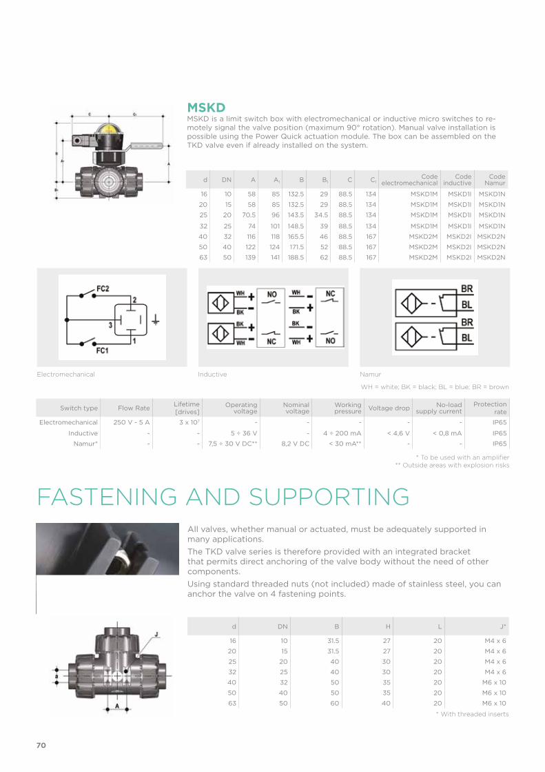
FASTENING AND SUPPORTING
d DN B H L J*
16 10 31.5 27 20 M4 x 6
20 15 31.5 27 20 M4 x 6
25 20 40 30 20 M4 x 6
32 25 40 30 20 M4 x 6
40 32 50 35 20 M6 x 10
50 40 50 35 20 M6 x 10
63 50 60 40 20 M6 x 10
* With threaded inserts
All valves, whether manual or actuated, must be adequately supported in many applications. The TKD valve series is therefore provided with an integrated bracket that permits direct anchoring of the valve body without the need of other components. Using standard threaded nuts (not included) made of stainless steel, you can anchor the valve on 4 fastening points.
Switch type Flow Rate Lifetime[drives]
Operating voltage
Nominal voltage
Working pressure Voltage drop No-load
supply currentProtection
rate
Electromechanical 250 V - 5 A 3 x 10⁷ - - - - - IP65
Inductive - - 5 ÷ 36 V - 4 ÷ 200 mA < 4,6 V < 0,8 mA IP65
Namur* - - 7,5 ÷ 30 V DC** 8,2 V DC < 30 mA** - - IP65
* To be used with an amplifier** Outside areas with explosion risks
Electromechanical Inductive Namur
WH = white; BK = black; BL = blue; BR = brown
MSKDMSKD is a limit switch box with electromechanical or inductive micro switches to re-motely signal the valve position (maximum 90° rotation). Manual valve installation is possible using the Power Quick actuation module. The box can be assembled on the TKD valve even if already installed on the system.
d DN A A1 B B1 C C1Code
electromechanicalCode
inductiveCode
Namur
16 10 58 85 132.5 29 88.5 134 MSKD1M MSKD1I MSKD1N
20 15 58 85 132.5 29 88.5 134 MSKD1M MSKD1I MSKD1N
25 20 70.5 96 143.5 34.5 88.5 134 MSKD1M MSKD1I MSKD1N
32 25 74 101 148.5 39 88.5 134 MSKD1M MSKD1I MSKD1N
40 32 116 118 165.5 46 88.5 167 MSKD2M MSKD2I MSKD2N
50 40 122 124 171.5 52 88.5 167 MSKD2M MSKD2I MSKD2N
63 50 139 141 188.5 62 88.5 167 MSKD2M MSKD2I MSKD2N
70
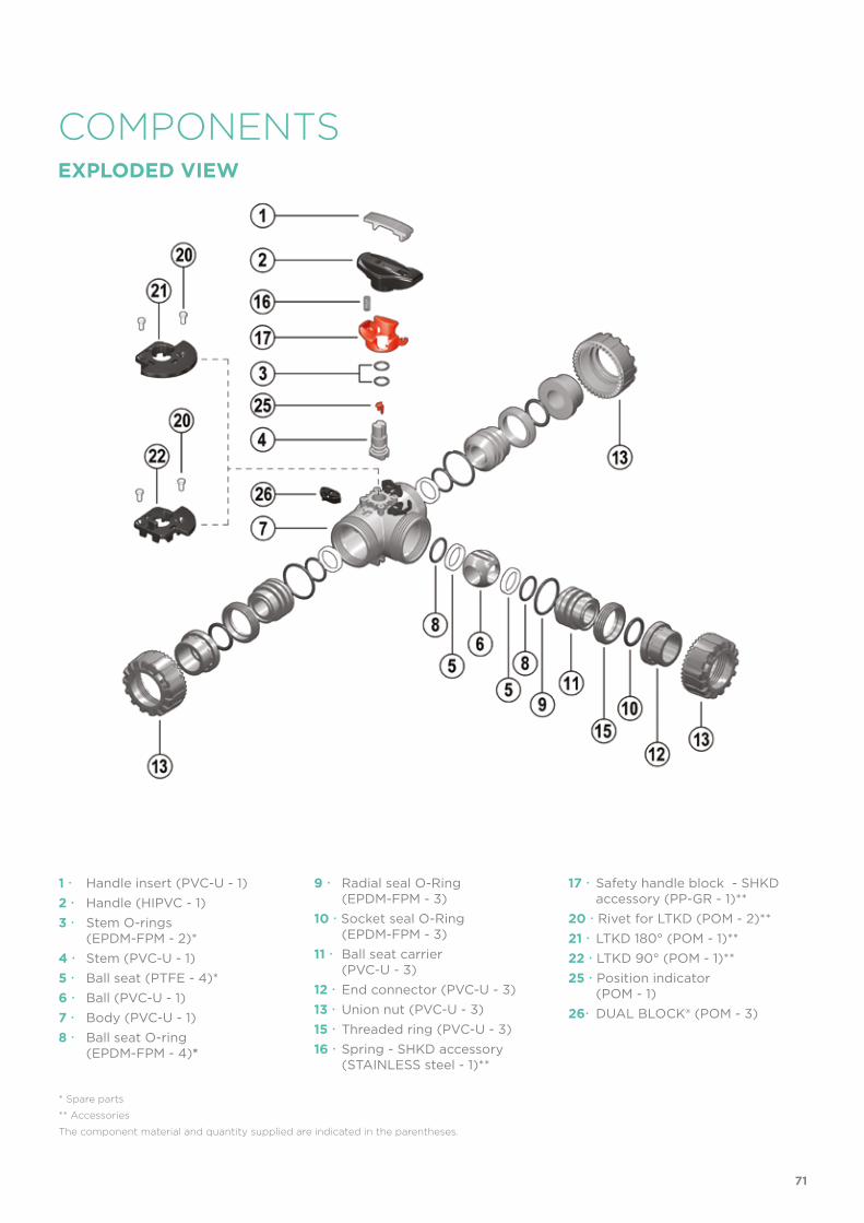
COMPONENTSEXPLODED VIEW
1 Handle insert (PVC-U - 1)2 Handle (HIPVC - 1)3 Stem O-rings
(EPDM-FPM - 2)*4 Stem (PVC-U - 1)5 Ball seat (PTFE - 4)*6 Ball (PVC-U - 1)7 Body (PVC-U - 1)8 Ball seat O-ring
(EPDM-FPM - 4)*
* Spare parts
** Accessories
The component material and quantity supplied are indicated in the parentheses.
9 Radial seal O-Ring (EPDM-FPM - 3)10 Socket seal O-Ring (EPDM-FPM - 3)11 Ball seat carrier
(PVC-U - 3)12 End connector (PVC-U - 3)13 Union nut (PVC-U - 3)15 Threaded ring (PVC-U - 3)16 Spring - SHKD accessory (STAINLESS steel - 1)**
17 Safety handle block - SHKD accessory (PP-GR - 1)**
20 Rivet for LTKD (POM - 2)**21 LTKD 180° (POM - 1)**22 LTKD 90° (POM - 1)**25 Position indicator (POM - 1)26 DUAL BLOCK® (POM - 3)
71

INSTALLATIONBefore proceeding with installation. please follow these instructions carefully:1) Check that the pipes to be connected to the valve are aligned in order to avoid
mechanical stress on the threaded joints.2) Check that the DUAL BLOCK® union nut locking device (26) is fitted to the valve
body.3) To release the union nuts (13), axially press the release lever to separate the lock
and then unscrew it in the counter-clockwise direction.4) Unscrew the three union nuts (13) and insert them on the pipe segments. 5) Solvent weld or screw the end connectors (12) onto the pipe ends.6) Position the valve body between the end connectors (12) and fully tighten the
union nuts (13) manually by rotating clockwise, without using wrenches or other tools that could damage the union nut surface.
7) Lock the union nuts by returning the DUAL BLOCK® to its housing, pressing on it until the hinges lock on the union nuts.
8) If necessary, support the pipework with FIP pipe clips or by means of the carrier built-into the valve itself (see paragraph “fastening and supporting”).
DISMOUNTING ASSEMBLY1) Isolate the valve from the line (re-
lease the pressure and empty the pipeline).
2) Unlock the union nuts by pressing the lever on the DUAL BLOCK® (26) along the axis and separate it from the union nut (fig. 1). It is also pos-sible to completely remove the block device from the body of the valve.
3) Unscrew the union nuts (13) and ex-tract the body (7).
4) After turning the handle (2) to the position with the three arrows point-ing at the three ports (for L-port ball with two arrows facing the ports a and b), extract the insert (1) from the handle (2) and insert the two protru-sions in the corresponding apertures in the threaded rings (15), extracting the carriers (11) by turning counter-clockwise.
5) Extract the ball (6) from the central port being careful not to damage the seat surface.
6) Remove the PTFE ball seats (5) and O-Rings (8, 9, 10) from the carriers (11).
7) Pull the handle (2) upwards to re-move it from the stem (4).
8) Press the stem (4) into the body and extract it.
9) Remove the PTFE ball seat (5) with relevant O-ring (8) from inside the valve body.
10) Remove the stem (4) O-rings (3) from their seats.
1) Insert the O-rings (3) on the stem (4).2) Insert the O-ring (8) in the seat in the
valve body and, next, the PTFE ball seat (5).
3) Insert the stem (4), from the interior, in the body, being sure the three marks on the socket correspond to the three outlets.
4) Insert the ball (6) from the central port b, being careful that the three bores match the three outlets (for L-port ball, the two bores must match the a and b outlets).
5) Insert the O-rings (8), PTFE ball seats (5), socket seal O-rings (10) and ra-dial seal O-rings (9) in their seats on the carriers (11).
6) Insert the three carriers (11) with the relevant threaded rings (15), screwing in clockwise with the handle insert (1) and starting from the one on the central outlet b.
7) Press the handle (2) on the stem (4), being careful to match the printed arrows with the lines on the stem (fig. 2-3).
8) Return the insert (1) in the handle (2)9) Insert the valve between the end
connectors (12) and tighten the union nuts (13), making sure that the socket seal O-rings (10) do not exit their seats.
Note: during assembly operations, it is advisable to lubricate the rubber seals. Mineral oils are not recommended for this task as they react aggressively with EPDM rubber.
Fig. 3
Fig. 4
Fig. 2
Fig. 1
72

Fig. 5
WARNINGS
The TKD valve can be equipped with a handle lock to prevent ball rotation (available as an accessory). When the block (16, 17) is installed, lift the lever (17) and rotate the handle.A padlock can also be installed on the handle to protect the system against tamper-ing (fig. 4).Seals can be adjusted using the extractable insert on the handle (fig. 5-6). After posi-tioning the ball as in figure 7-8, using this insert as a tool you can adjust the seals by screwing in the carriers following the indicated sequence (fig. 7-8).A further fine-tuning of the seals can be done with the valve installed on the pipe by simply tightening the union nuts.This "micro adjustment", only possible with FIP valves thanks to the patented "Seat stop system", allows the seal to be recovered where PTFE ball seats are worn due to a high number of operations.
Always avoid sudden closing manoeuvres and protect the valve from accidental operations.
Fig. 8
Fig. 7
Fig. 6
1
1
2
2
3
3
73


VXE DN 10÷50PVC-U
Easyfit 2-way ball valve

76
Technical specificationsConstruction Easyfit 2-way True Union ball valve with locked
carrierSize range DN 10 ÷ 50Nominal pressure PN 16 with water at 20 °CTemperature range 0 °C ÷ 60 °CCoupling standards Solvent welding: EN ISO 1452, EN ISO 15493, BS 4346-1,
DIN 8063, NF T54-028, ASTM D 2467, JIS K 6743. Pipe coupling capacity according to EN ISO 1452, EN ISO 15493, DIN 8062, NF T54-016, ASTM D 1785, JIS K 6741
Thread: ISO 228-1, DIN 2999, ASTM D 2467, JIS B 0203
Reference standards Construction criteria: EN ISO 16135, EN ISO 1452, EN ISO 15493Test methods and requirements: ISO 9393Installation criteria: DVS 2204, DVS 2221, UNI 11242
Valve material PVC-USeal material EPDM, FPM (standard size O-Ring);
PTFE (ball seats)
Control options Manual control
VXE
FIP and Giugiaro Design designed anddeveloped VXE Easyfit, the innovative True Union ballwith union nuttightening control that permitssimple and safe installation for reliable service in time. This valve is also equipped with the customisable Labelling System.
EASYFIT 2-WAY BALL VALVE
• Patented Easyfit system: innovative mechanism based on the principle of the bevel gear pair that controls valve union nut rotation during installa-tion
• Connection system for solvent weld and threaded joints• Valve material compatibility (PVC-U) and elastomer seal elements (EPDM
or FPM), with water, drinking water and other food substances as per cur-rent regulations
• Easy radial dismounting allowing quick replacement of O-rings and ball seats without any need for tools
• PN16 True Union valve body made for PVC-U injection moulding and Eu-ropean Directive 97/23/EC compliant for PED pressurised equipment. ISO 9393 compliant test requirements
• Short face to face dimension according to international regulation ISO 7508 series III and European regulation EN 1452 ”short” and fully inter-changeable with previous VX Ergo series models
• Option of dismounting downstream pipes with the valve in the closed position
• Floating full bore ball with high surface finish made in CNC work stations to achieve precise dimensional tolerance and high surface finish
DN 10÷50
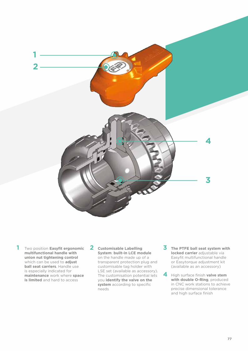
77
1 Two position Easyfit ergonomic multifunctional handle with union nut tightening control which can be used to adjust ball seat carriers. Handle use is especially indicated for maintenance work where space is limited and hard to access
2 Customisable Labelling System: built-in LCE module on the handle made up of a transparent protection plug and customisable tag holder with LSE set (available as accessory). The customisation potential lets you identify the valve on the system according to specific needs
3 The PTFE ball seat system with locked carrier adjustable via Easyfit multifunctional handle or Easytorque adjustment kit (available as an accessory)
4 High surface finish valve stem with double O-Ring, produced in CNC work stations to achieve precise dimensional tolerance and high surface finish
21
4
3

78
TECHNICAL DATA
-40 -20 0 20 40 60 80 100 120 140 °C
16
14
12
10
8
6
4
2
0
Wo
rkin
g p
ress
ure
Working temperature
barPRESSURE VARIATION ACCORDING TO TEMPERATURE
For water and harmless fluids to which the material is classified as CHEMICALLY RESISTANT. In other cases, a reduction of the nominal PN pressure is required (25 years with safety factor).
The information in this leaflet is provided in good faith. No liability will be accepted concerning technical data that is not directly covered by recognised international standards. FIP reserves the right to carry out any modification. Products must be installed and maintained by qualified personnel.
PRESSURE DROP GRAPH
Pre
ssu
re d
rop
Flow Rate
bar1 10 100 1000 10000 l/min
1
0.1
0.01
0.001
DN
15
DN
10
DN
20
DN
25
DN
32
DN
40
DN
50
KV100 FLOW COEFFICIENTThe Kv100 flow coefficient is the Q flow rate of litres per minute of water at a temperature of 20°C that will generate ∆p= 1 bar pressure drop at a certain valve position.The Kv100 values shown in the table are calculated with the valve completely open.
DN 10 15 20 25 32 40 50
Kv100 l/min 80 200 385 770 1100 1750 3400

79
R DN PN B C C1 E H L Z g EPDM Code FPM Code
3/8” 10 16 49 64 44 54 82 11.4 59.2 180 VXEFV038E VXEFV038F
1/2” 15 16 49 64 44 54 90 15 60 175 VXEFV012E VXEFV012F
3/4” 20 16 62 78 55 63 93 16.3 60.4 260 VXEFV034E VXEFV034F
1” 25 16 71 87 60 72 110 19.1 71.8 365 VXEFV100E VXEFV100F
1” 1/4 32 16 82 102 72 85 127 21.4 84.2 565 VXEFV114E VXEFV114F
1” 1/2 40 16 92 109 76 100 131 21.4 88.2 795 VXEFV112E VXEFV112F
2” 50 16 110 133 94 118 161 25.7 109.6 1325 VXEFV200E VXEFV200F
DIMENSIONS
d DN PN B C C1 E H L Z g EPDM Code FPM Code
16 10 16 49 64 44 54 82 14 54 180 VXEIV016E VXEIV016F
20 15 16 49 64 44 54 82 16 50 175 VXEIV020E VXEIV020F
25 20 16 62 78 55 63 91 19 53 260 VXEIV025E VXEIV025F
32 25 16 71 87 60 72 103 22 59 365 VXEIV032E VXEIV032F
40 32 16 82 102 72 85 120 26 68 565 VXEIV040E VXEIV040F
50 40 16 92 109 76 100 139 31 77 795 VXEIV050E VXEIV050F
63 50 16 110 133 94 118 174 38 98 1325 VXEIV063E VXEIV063F
VXEIVEasyfit 2-way ball valve with female ends for solvent welding, metric series
VXEFVEasyfit 2-way ball valve with BSP threaded female ends
d DN PN B C C1 E H L Z g EPDM Code FPM Code
1/2” 15 16 49 64 44 54 82 16.5 49 175 VXELV012E VXELV012F
3/4” 20 16 62 78 55 63 91 19 53 260 VXELV034E VXELV034F
1” 25 16 71 87 60 72 103 22.5 58 365 VXELV100E VXELV100F
1” 1/4 32 16 82 102 72 85 120 26 68 565 VXELV114E VXELV114F
1” 1/2 40 16 92 109 76 100 139 30 79 795 VXELV112E VXELV112F
2” 50 16 110 133 94 118 174 36 102 1325 VXELV200E VXELV200F
VXELVEasyfit 2-way ball valve with female ends for solvent welding, BS series

d DN PN B C C1 E H L Z g EPDM Code FPM Code
1/2” 15 16 49 64 44 54 96 22.5 51 175 VXEAV012E VXEAV012F
3/4” 20 16 62 78 55 63 105 25.5 54 260 VXEAV034E VXEAV034F
1” 25 16 71 87 60 72 117 28.7 59.5 365 VXEAV100E VXEAV100F
1” 1/4 32 16 82 102 72 85 136 32 72 565 VXEAV114E VXEAV114F
1” 1/2 40 16 92 109 76 100 147 35 77 795 VXEAV112E VXEAV112F
2” 50 16 110 133 94 118 174 38.2 97.6 1325 VXEAV200E VXEAV200F
VXEAVEasyfit 2-way ball valve with female ends for solvent welding, ASTM series
R DN PN B C C1 E H L Z g EPDM Code FPM Code
3/8” 10 16 49 64 44 54 82 13.7 54.6 180 VXENV038E VXENV038F
1/2” 15 16 49 64 44 54 90 17.8 54.4 175 VXENV012E VXENV012F
3/4” 20 16 62 78 55 63 93 18 57 260 VXENV034E VXENV034F
1” 25 16 71 87 60 72 110 22.6 64.8 365 VXENV100E VXENV100F
1” 1/4 32 16 82 102 72 85 127 25.1 76.8 565 VXENV114E VXENV114F
1” 1/2 40 16 92 109 76 100 131 24.7 81.6 795 VXENV112E VXENV112F
2” 50 16 110 133 94 118 161 29.6 101.8 1325 VXENV200E VXENV200F
VXENVEasyfit 2-way ball valve with female ends, NPT thread
d DN PN B C C1 E H L Z g EPDM Code FPM Code
1/2” 15 16 49 64 44 54 110 30 50 195 VXEJV012E VXEJV012F
3/4” 20 16 62 78 55 63 123 35 53 285 VXEJV034E VXEJV034F
1” 25 16 71 87 60 72 139 40 59 395 VXEJV100E VXEJV100F
1” 1/4 32 16 82 102 72 85 156 44 68 600 VXEJV114E VXEJV114F
1” 1/2 40 16 92 109 76 100 187 55 77 835 VXEJV112E VXEJV112F
2” 50 16 110 133 94 118 228 63 102 1375 VXEJV200E VXEJV200F
VXEJVEasyfit 2-way ball valve with female ends for solvent welding, JIS series
80

R DN PN B C C1 E H L Z g EPDM Code FPM Code
1/2” 15 16 49 64 44 54 82 16 50 175 VXEGV012E VXEGV012F
3/4” 20 16 62 78 55 63 91 19 53 260 VXEGV034E VXEGV034F
1” 25 16 71 87 60 72 103 22 59 365 VXEGV100E VXEGV100F
1” 1/4 32 16 82 102 72 85 120 25 70 565 VXEGV114E VXEGV114F
1” 1/2 40 16 92 109 76 100 139 26 87 795 VXEGV112E VXEGV112F
2” 50 16 110 133 94 118 174 31 112 1325 VXEGV200E VXEGV200F
VXEGVEasyfit 2-way valve with female ends, JIS thread
d DN PN B C C1 E H L Z g EPDM Code FPM Code
20 15 16 49 64 44 54 154 41 72 180 VXEBEV020E VXEBEV020F
25 20 16 62 78 55 63 186 52 82 269 VXEBEV025E VXEBEV025F
32 25 16 71 87 60 72 199 54.5 90 379 VXEBEV032E VXEBEV032F
40 32 16 82 102 72 85 217 56 105 591 VXEBEV040E VXEBEV040F
50 40 16 92 109 76 100 236 58 120 851 VXEBEV050E VXEBEV050F
63 50 16 110 133 94 118 268 66 136 1407 VXEBEV063E VXEBEV063F
VXEBEVEasyfit 2-way ball valve with PE100 SDR 11 male end connectors for butt welding or electrofusion (CVDE)
81

LCETransparent protection plug with tag holder
d DN Code
16 10 LCE020
20 15 LCE020
25 20 LCE025
32 25 LCE032
40 32 LCE040
50 40 LCE050
63 50 LCE063
ACCESSORIES
d DN PN L SDR Code
20 15 16 55 11 CVDE11020
25 20 16 70 11 CVDE11025
32 25 16 74 11 CVDE11032
40 32 16 78 11 CVDE11040
52 40 16 84 11 CVDE11050
63 50 16 91 11 CVDE11063
CVDELong spigot PE100 end connectors for joints with electrofusion fittings or for butt welding
EASYTORQUE KITKit for union nut tightening adjustment and ball seat carrier for Easyfit DN 10÷50 valves.
d DN Union nut tightening torque*
Seat carrier tightening torque* Code
3/8”-1/2” 10-15 5 N m - 3,69 Lbf ft 3 N m - 2,21 Lbf ft KET01
3/4” 20 5 N m - 3,69 Lbf ft 3 N m - 2,21 Lbf ft KET01
1” 25 6 N m - 4,43 Lbf ft 4 N m - 2,95 Lbf ft KET01
1” 1/4 32 7 N m - 5,16 Lbf ft 4 N m - 2,95 Lbf ft KET01
1” 1/2 40 8 N m - 5,90 Lbf ft 5 N m - 3,69 Lbf ft KET01
2” 50 10 N m - 7,38 Lbf ft 6 N m - 4,43 Lbf ft KET01
*calculated in ideal installation conditions
82

CUSTOMISATION
LSECustomisation and label printing set for Easyfit handle made up of precut adhesive sheets and software for guided label creation.
The VXE DN 10÷50 Easyfit valve is equipped with the customisable Labelling System. This system lets you create special labels to insert in the handle. This makes it ex-tremely easy to apply company logos, identification serial numbers or service indica-tions such as, for example, the valve function in the system, the transported fluid, but also specific information for customer service, such as the customer name or installa-tion date or location on the valves.The specific LCE module is a standard supply and is made up of a rigid transparent water-resistant PVC plug (A) and white tag holder (B) made of the same material, one side of which bears the FIP logo (fig. 1). The holder, inserted in the plug, can be removed and, once overturned, used for cus-tomisation by applying labels printed with the software supplied with the LSE set.Proceed as follows to apply the label on the valve:1) Extract the handle from the valve body and extract the transparent plug.2) Extract the tag holder from the transparent plug (fig. 2).3) Apply the adhesive label on the tag holder to align the profiles matching the tab
position.4) Re-insert the tag holder in the transparent plug so that the label is protected from
the elements.5) Apply the transparent plug on the handle matching the two fittings (one narrow
and one wide) with their housings (fig. 3).
d DN Code
16 10 LSE020
20 15 LSE020
25 20 LSE025
32 25 LSE032
40 32 LSE040
50 40 LSE050
63 50 LSE063
Fig. 1
Fig. 2
Fig. 3
A
B
83

COMPONENTSEXPLODED VIEW
1a Transparent protection plug (PVC - 1)2 Stem O-Ring
(EPDM - FPM 2)*3 Stem (PVC-U - 1)4 Body (PVC-U - 1) 5 Ball (PVC-U - 1)
* Spare parts
The component material and quantity supplied are indicated in the parentheses.
6 Radial seal O-Ring (EPDM-FPM - 1)7 End connector (PVC-U - 2)8 Ball seat carrier
(PVC-U - 1)9 Ball seat (PTFE - 2)*
10 Socket seal O-Ring (EPDM-FPM - 2)12 Handle (HIPVC - 1)13 Union nut (PVC-U - 2)14 Tag holder
(PVC-U - 1)
84

INSTALLATIONBefore proceeding with installation. please follow these instructions carefully:1) Check that the pipes to be connected to the valve are aligned in order to avoid
mechanical stress on the threaded joints.2) Unscrew the union nuts from the valve body (4) and slide them onto the pipe.3) Solvent weld or screw the end connectors (7) onto the pipe segments.4) Position the valve body between the end connectors (fig. 5). Warning: if a high pressure test is required, always position the body with the
"REGULAR" label upstream from the fluid direction. 5) Fit the union nuts on the valve body and manually tighten clockwise until they
become hard to turn; do not use wrenches or other tools that can damage the union nut surfaces.
6) Extract the handle (12) from the valve body and extract the transparent plug (1a).7) Overturn the handle and insert in on the valve stem matching the handle teeth (A)
with the union nut teeth (B) (fig. 8-9).8) Turn the handle counter-clockwise to fully tighten the union nut. The rotation
directions to tighten (TIGHTEN) and loosen (UNTIGHTEN) the union nuts are indicated on the handle (fig. 10). Generally, if pipes are not offset, one turn is suf-ficient for correct tightening.
DISMOUNTING ASSEMBLY1) Isolate the valve from the line (re-
lease the pressure and empty the pipeline).
2) Fully unscrew the union nuts (13) from the valve body and slide the body out sideways (fig. 4-5).
To do this, we recommend you use the Easyfit handle as a tool (fig. 8-9)
3) Before dismounting, hold the valve in a vertical position and open it 45° to drain any liquid that might remain.
4) After closing the valve, remove the handle (12) (fig. 6) and insert the two protrusions in the lower side in the two apertures and in the carrier pas-sage bore (8) extracting it by turning counter-clockwise (fig. 7).
5) Press on the ball from the side oppo-site the "REGULAR" label, being sure not to scratch it, until the ball seat exits (9), then extract the ball (5).
6) Press the stem (3) inwards until it ex-its the body.
7) Remove the O-Rings (2, 6, 10) and ball seats (9) extracting them from their seats, as illustrated in the ex-ploded view.
1) All the O-Rings (2, 6, 10) must be in-serted in their grooves as shown in the exploded view.
2) Insert the stem (3) from inside the body (4).
3) Place the ball seats (9) in the housings in the body (4) and in the carrier (8).
4) Insert the ball (5) rotating it to the closed position.
5) Screw the carrier (8) into the body and tighten up in the clockwise direction us-ing the handle (12) to limit stop.
6) Position the valve between the end con-nectors (7) and tighten the union nuts (13) clockwise using the Easyfit multi-functional handle, being sure the socket seal O-Rings (10) do not exit the seats.
7) Position the handle (12) on the stem (3).
Note: during assembly operations, it is advisable to lubricate the rubber seals. Mineral oils are not recommended for this task as they react aggressively with EPDM rubber.
Fig. 5
Fig. 4
Fig. 6
Fig. 7
85

WARNINGS
9) Repeat point 7 for the other union nut. Note: A small force applied on the handle develops a torque much higher than
manual tightening. You can also, using the Easytorque kit (fig. 11), supplied as an accessory, tighten
union nuts using a torque wrench to quantify the force and thus monitor the stress applied to the thermoplastic threads according to the installation indica-tions in the instructions enclosed with the kit.
10) Apply the plug (1a) on the handle (12) matching the two fittings (one narrow and one wide) with the relevant housings on the handle (fig. 3).
11) Install the handle (12) on the stem (3) again.12) If necessary, support the pipe with FIP pipe clip model ZIKM and DSM distance
plates.
- If volatile liquid such as Hydrogen Peroxide (H2O2) or Sodium Hypochlorite (NaCIO) is used, for safety reasons we recommend you contact the service centre. These liquids, upon vaporising, could create hazardous over pressures in the area between the body and ball.
- Do not used compressed air or other gases to test thermoplastic lines.- Always avoid sudden closing manoeuvres and protect the valve from accidental
manoeuvres.
Fig. 10
Fig. 11
Fig. 8
Fig. 9
A
B
86


VXE DN 65÷100PVC-U
Easyfit 2-way ball valve

90
Technical specificationsConstruction Easyfit 2-way True Union ball valve with locked
carrierSize range DN 65 ÷ 100Nominal pressure PN 16 with water at 20 °CTemperature range 0 °C ÷ 60 °CCoupling standards Solvent welding: EN ISO 1452, EN ISO 15493, BS 4346-1,
DIN 8063, NF T54-028, ASTM D 2467, JIS K 6743. Pipe coupling capacity according to EN ISO 1452, EN ISO 15493, DIN 8062, NF T54-016, ASTM D 1785, JIS K 6741
Thread: ISO 228-1, DIN 2999, ASTM D 2467, JIS B 0203
Reference standards Construction criteria: EN ISO 16135, EN ISO 1452, EN ISO 15493Test methods and requirements: ISO 9393Installation criteria: DVS 2204, DVS 2221, UNI 11242Actuator couplings: ISO 5211
Valve material PVC-USeal material EPDM, FPM (standard size O-Ring);
PTFE, PE (ball seats)
Control options Manual control, electric actuator, pneumatic actuator
VXE
FIP and Giugiaro Designdesigned anddeveloped VXE Easyfit,the innovative True Union ball valve with union nut tightening control system that permits simple and safe installation for reliable service in time. This valve is also equipped with the customisable Labelling System.
EASYFIT 2-WAY BALL VALVE
• Patented Easyfit system: innovative mechanism based on the multifunc-tional handle quick release mechanism that permits union nut rotation during valve installation and ball carrier adjustment
• Connection system for solvent weld and threaded joints• Valve material compatibility (PVC-U) and elastomer seal elements (EPDM
or FPM), with water, drinking water and other food substances as per cur-rent regulations
• Easy radial dismounting allowing quick replacement of O-rings and ball seats without any need for tools
• PN16 True Union valve body made for PVC-U injection moulding and Eu-ropean Directive 97/23/EC compliant for PED pressurised equipment. ISO 9393 compliant test requirements
• Valve body with built in anchoring frame for the special Power Quick module dedicated to accessory or pneumatic and electric actuator instal-lation
• Option of dismounting downstream pipes with the valve in the closed position
• Floating full bore ball with high surface finish made in CNC work stations to achieve precise dimensional tolerance and high surface finish
DN 65÷100
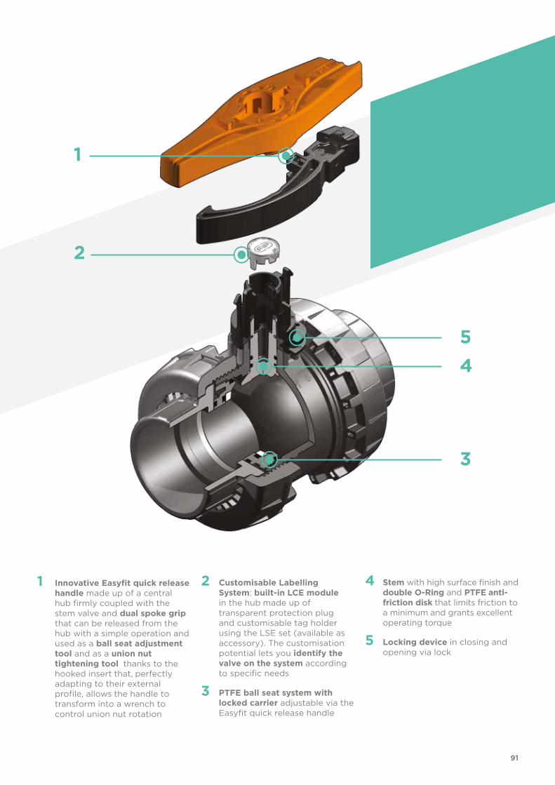
1
91
1 Innovative Easyfit quick release handle made up of a central hub firmly coupled with the stem valve and dual spoke grip that can be released from the hub with a simple operation and used as a ball seat adjustment tool and as a union nut tightening tool thanks to the hooked insert that, perfectly adapting to their external profile, allows the handle to transform into a wrench to control union nut rotation
2 Customisable Labelling System: built-in LCE module in the hub made up of transparent protection plug and customisable tag holder using the LSE set (available as accessory). The customisation potential lets you identify the valve on the system according to specific needs
3 PTFE ball seat system with locked carrier adjustable via the Easyfit quick release handle
4 Stem with high surface finish and double O-Ring and PTFE anti-friction disk that limits friction to a minimum and grants excellent operating torque
5 Locking device in closing and opening via lock
2
3
45

92
TECHNICAL DATA
-40 -20 0 20 40 60 80 100 120 140 °C
16
14
12
10
8
6
4
2
0
Wo
rkin
g p
ress
ure
Working temperature
barPRESSURE VARIATION ACCORDING TO TEMPERATURE
For water and harmless fluids to which the material is classified as CHEMICALLY RESISTANT. In other cases, a reduction of the nominal PN pressure is required (25 years with safety factor).
KV100 FLOW COEFFICIENTThe Kv100 flow coefficient is the Q flow rate of litres per minute of water at a temperature of 20°C that will generate ∆p= 1 bar pressure drop at a certain valve position.The Kv100 values shown in the table are calculated with the valve completely open.
PRESSURE DROP GRAPH
Pre
ssu
re d
rop
Flow Rate
bar1 10 100 1000 10000 l/min
1
0.1
0.01
0.001
DN
65
DN
80
DN
100
DN 65 80 100
Kv100 l/min 5000 7000 9400
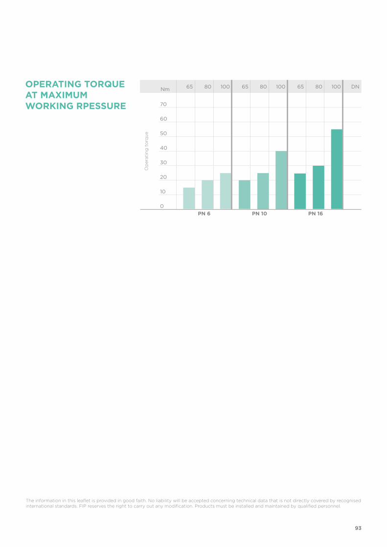
OPERATING TORQUE AT MAXIMUM WORKING RPESSURE
Nm 65 80 100 65 80 100 65 80 100 DN
70
60
50
40
30
20
10
0
Op
erat
ing
to
rqu
e
PN 6 PN 10 PN 16
93
The information in this leaflet is provided in good faith. No liability will be accepted concerning technical data that is not directly covered by recognised international standards. FIP reserves the right to carry out any modification. Products must be installed and maintained by qualified personnel.

R DN PN B C C1 E H L Z g CodePTFE - EPDM
CodePTFE - FPM
CodePE - EPDM
2” 1/2 65 16 142 214 115 157 211 30.2 150.6 2750 VXEFV212E VXEFV212F VXEFV212M
3” 80 16 151 239 126 174 248 33.3 181.4 3432 VXEFV300E VXEFV300F VXEFV300M
4” 100 16 174.5 270 145 212 283 39.3 204.4 5814 VXEFV400E VXEFV400F VXEFV400M
d DN PN B C C1 E H L Z g CodePTFE - EPDM
CodePTFE - FPM
CodePE - EPDM
2” 1/2 65 16 142 214 115 157 211 44 123 2750 VXELV212E VXELV212F VXELV212M
3” 80 16 151 239 126 174 248 51 146 3432 VXELV300E VXELV300F VXELV300M
4” 100 16 174.5 270 145 212 283 63 157 5814 VXELV400E VXELV400F VXELV400M
d DN PN B C C1 E H L Z g CodePTFE - EPDM
CodePTFE - FPM
CodePE - EPDM
75 65 16 142 214 115 157 211 44 123 2750 VXEIV075E VXEIV075F VXEIV075M
90 80 16 151 239 126 174 248 51 146 3432 VXEIV090E VXEIV090F VXEIV090M
110 100 16 174.5 270 145 212 283 61 161 5814 VXEIV110E VXEIV110F VXEIV110M
VXEIVEasyfit 2-way ball valve with female ends for solvent welding, metric series
VXEFVEasyfit 2-way ball valve with BSP threaded female ends
VXELVEasyfit 2-way ball valve with female ends, BS series
VXEAVEasyfit 2-way ball valve with female ends, ASTM series
d DN PN B C C1 E H L Z g CodePTFE - EPDM
CodePTFE - FPM
CodePE - EPDM
2” 1/2 65 16 142 214 115 157 211 44.5 122 2750 VXEAV212E VXEAV212F VXEAV212M
3” 80 16 151 239 126 174 248 48 152 3432 VXEAV300E VXEAV300F VXEAV300M
4” 100 16 174.5 270 145 212 283 57.5 168 5814 VXEAV400E VXEAV400F VXEAV400M
DIMENSIONS
94
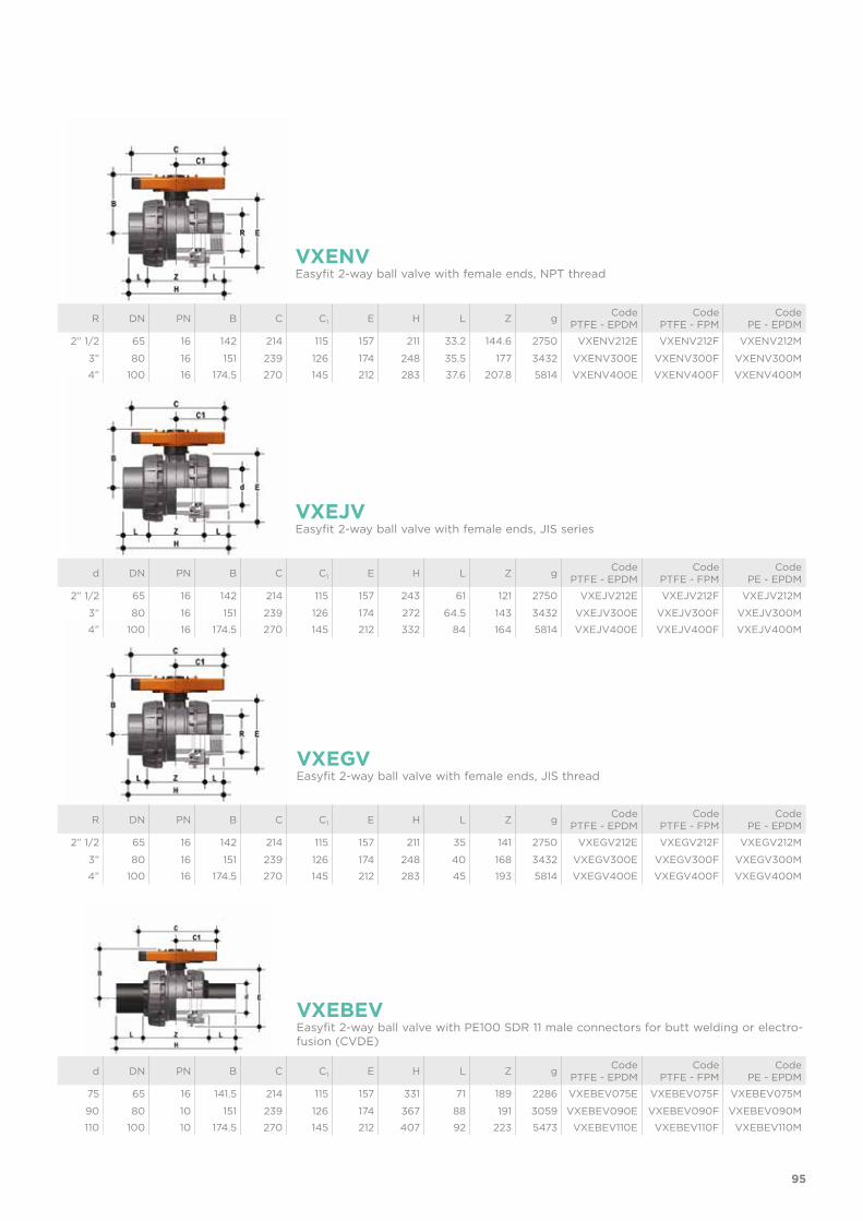
R DN PN B C C1 E H L Z g CodePTFE - EPDM
CodePTFE - FPM
CodePE - EPDM
2” 1/2 65 16 142 214 115 157 211 35 141 2750 VXEGV212E VXEGV212F VXEGV212M
3” 80 16 151 239 126 174 248 40 168 3432 VXEGV300E VXEGV300F VXEGV300M
4” 100 16 174.5 270 145 212 283 45 193 5814 VXEGV400E VXEGV400F VXEGV400M
d DN PN B C C1 E H L Z g CodePTFE - EPDM
CodePTFE - FPM
CodePE - EPDM
75 65 16 141.5 214 115 157 331 71 189 2286 VXEBEV075E VXEBEV075F VXEBEV075M
90 80 10 151 239 126 174 367 88 191 3059 VXEBEV090E VXEBEV090F VXEBEV090M
110 100 10 174.5 270 145 212 407 92 223 5473 VXEBEV110E VXEBEV110F VXEBEV110M
VXENVEasyfit 2-way ball valve with female ends, NPT thread
VXEGVEasyfit 2-way ball valve with female ends, JIS thread
VXEBEVEasyfit 2-way ball valve with PE100 SDR 11 male connectors for butt welding or electro-fusion (CVDE)
VXEJVEasyfit 2-way ball valve with female ends, JIS series
R DN PN B C C1 E H L Z g CodePTFE - EPDM
CodePTFE - FPM
CodePE - EPDM
2” 1/2 65 16 142 214 115 157 211 33.2 144.6 2750 VXENV212E VXENV212F VXENV212M
3” 80 16 151 239 126 174 248 35.5 177 3432 VXENV300E VXENV300F VXENV300M
4” 100 16 174.5 270 145 212 283 37.6 207.8 5814 VXENV400E VXENV400F VXENV400M
d DN PN B C C1 E H L Z g CodePTFE - EPDM
CodePTFE - FPM
CodePE - EPDM
2” 1/2 65 16 142 214 115 157 243 61 121 2750 VXEJV212E VXEJV212F VXEJV212M
3” 80 16 151 239 126 174 272 64.5 143 3432 VXEJV300E VXEJV300F VXEJV300M
4” 100 16 174.5 270 145 212 332 84 164 5814 VXEJV400E VXEJV400F VXEJV400M
95

LSE
LCE
Customisation and label printing set for Easyfit handle made up of precut adhesive sheets and software for guided label creation.
Transparent protection plug with tag holder
d inch DN A A1 B B min CodeISO pipe
CodeASTM-BS pipe
75 2” 1/2 65 76 63 159 364 PSE090 PSE300
90 3” 80 76 63 166 371 PSE090 PSE300
110 4” 100 76 63 186 433 PSE110 PSE400
PSEStem extension
d DN Code
75 65 LSE040
90 80 LSE040
110 100 LSE040
d DN Code
75 65 LCE040
90 80 LCE040
110 100 LCE040
POWER QUICK EASYFITThe valve can be equipped with pneumatic or electric standard actuators and gearbox for heavy-duty operations, using the PP-GR module reproducing the drilling pattern foreseen by ISO 5211.
d DN B2 Q T p x j P x J Code
75 65 129 14 16 F05 x 6,5 F07 x 8,5 PQE090
90 80 136 14 16 F05 x 6,5 F07 x 8,5 PQE090
110 100 156 17 19 F05 x 6,5 F07 x 8,5 PQE110
ACCESSORIES
d DN PN L SDR Code
75 65 16 111 11 CVDE11075
90 80 16 118 11 CVDE11090VXE
110 100 16 127 11 CVDE11110VXE
CVDELong spigot PE100 end connectors for joints with electrofusion fittings or for butt welding
96

CUSTOMISATIONThe VXE DN 65÷100 Easyfit valve is equipped with the customisable Labelling System. This system lets you create special labels to insert in the handle. This makes it ex-tremely easy to apply company logos, identification serial numbers or service indica-tions such as, for example, the valve function in the system, the transported fluid, but also specific information for customer service, such as the customer name or installa-tion date or location on the valves. The specific LCE module is a standard supply and is made up of a rigid transparent water-resistant PVC plug (A) and white tag holder (B) made of the same material, one side of which bears the FIP logo (fig. 1). The holder, inserted in the plug, can be removed and, once overturned, used for cus-tomisation by applying labels printed with the software supplied with the LSE set.Proceed as follows to apply the label on the valve:1) Release the handle from the central hub (C) and extract the transparent plug.2) Extract the tag holder from the transparent plug (fig. 2).3) Apply the adhesive label on the tag holder to align the profiles matching the tab
position.4) Re-insert the tag holder in the transparent plug so that the label is protected from
the elements.5) Apply the transparent plug on the central hub matching the two fittings (one nar-
row and one wide) with the relevant housings.
Fig. 1
Fig. 2
Switch type Flow Rate Lifetime[drives]
Operating voltage
Nominal voltage
Working pressure Voltage drop No-load sup-
ply currentProtection
rate
Electromechanical 250 V - 5 A 3 x 10⁷ - - - - - IP65
Inductive - - 5 ÷ 36 V - 4 ÷ 200 mA < 4,6 V < 0,8 mA IP65
Namur* - - 7,5 ÷ 30 V DC** 8,2 V DC < 30 mA** - - IP65
* To be used with an amplifier** Outside areas with explosion risks
Electromechanical Inductive Namur
WH = white; BK = black; BL = blue; BR = brown
MSEMSE is a limit switch box with electromechanical or inductive micro switches to remote-ly signal the valve position. Manual valve installation is possible using the Power Quick Easyfit actuation module.The box can be assembled on the VXE valve even if already installed on the system.
d DN A B B1Code
electromechanicalCode
inductiveCode
Namur
75 65 139 203 79 MSE1M MSE1I MSE1N
90 80 146 210 87 MSE1M MSE1I MSE1N
110 100 166 231 106 MSE2M MSE2I MSE2N
A
B
C
97

COMPONENTSEXPLODED VIEW
1 Hooked Easyfit multifunctional handle insert (PP-GR - 1)
2 Easyfit multifunctional handle (HIPVC - 1)3 Stem O-Ring (FPM, EPDM** - 2)*4 Stem (PVC-U - 1) 5 Ball seat (PTFE, PE** - 2)*6 Ball (PVC-U - 1)*
* Spare parts
** For the VXE-PE version: EPDM O-ring (3, 8, 9, 10), PE ball seat (5)
The component material and quantity supplied are indicated in the parentheses.
7 Body (PVC-U - 1)8 Ball seat O-Ring
(FPM, EPDM** - 2)*9 Radial seal O-Ring (FPM, EPDM** - 1)*10 Socket seal O-Ring (FPM, EPDM** - 2)*11 Ball seat carrier
(PVC-U - 1)12 End connector (PVC-U - 2)13 Union nut (PVC-U - 2)
14 Transparent protection plug (PVC - 1)14a Grey protection plug for
VXE-PE version (PVC - 1)15 Central hub (HIPVC - 1)16 Anti-friction disk (PTFE - 1)*17 Tag holder (PVC-U - 1)18 Locking device plate (HIPVC - 1)19 Self-tapping screw (STAINLESS steel - 2)
98

INSTALLATIONBefore proceeding with installation. please follow these instructions carefully:1) Check that the pipes to be connected to the valve are aligned in order to avoid
mechanical stress on the threaded joints.2) Unscrew the union nuts (13) from the body (7) and insert them in the pipe segments.3) Solvent weld or screw the end connectors (12) onto the pipe segments.4) Position the valve body between the end connectors. Warning: if a high pressure test is required, always position the body with the
"REGULAR" label upstream from the fluid direction.5) Place the union nuts on the valve body and start tightening manually clockwise
until they are hard to turn. To complete tightening, extract the Easyfit quick re-lease multifunctional handle (2) pushing on the centre of the central hub hinges (15) (fig. 3 and 4)
DISMOUNTING ASSEMBLY1) Isolate the valve from the line (re-
lease the pressure and empty the pipeline).
2) Extract the Easyfit multifunctional handle from the central hub press-ing on the centre of the hub hinges (fig. 5) and use it as a wrench to fully unscrew the union nuts (13) from the valve body and slide the body out sideways (fig. 5).
3) Reposition the handle on the central hub.
4) Before dismounting, hold the valve in a vertical position and open it 45° to drain any liquid that might remain.
5) Open the valve. 6) Remove the ball seat carrier (11) us-
ing the Easyfit quick release handle. Insert the two protrusions at the top of the handle in the seat carriers (11) and unscrew, extracting it by turning counter-clockwise (fig. 6).
7) Press on the ball from the side oppo-site the "REGULAR" label, being sure not to scratch it, until the ball seat exits (5), then extract the ball (6).
8) Remove the central hub (15) firmly sliding it off the stem (4). Press the stem inwards and extract it from the body and remove the anti-friction disk (16).
9) Remove the O-Ring (3, 8, 9, 10) and ball seats (5) extracting them from their seats, as illustrated in the ex-ploded view.
1) All the O-rings (3, 8, 9, 10) must be inserted in their grooves as shown in the exploded view.
2) Place the anti-friction disk (16) on the stem (4) and insert it in the body (7).
3) Place the ball seats (5) in the hous-ings in the body (7) and in the carrier (11).
4) Insert the ball (6) rotating it to the closed position.
5) Screw the carrier (11) into the body and tighten up in the clockwise di-rection using the handle (2) to limit stop.
6) Place the central hub (15) on the stem (4) firmly pressing down to match the internal hub key with one of the two seats on the stem.
7) Position the valve between the end connectors (12) and tighten the union nuts clockwise (13) using the Easyfit multifunctional handle (fig. 9) and being sure the socket seal O-rings (10) do not exit the seats.
8) Re-insert the hooked insert (1) in the housing on the handle (2).
9) Reposition the handle on the central hub making sure the two grooves in the central handle bore match the two grooves on the side of the hub and slightly press down until the two hinges click. Fig. 5
Fig. 6
Fig. 4
Fig. 3
Note: during assembly operations, it is advisable to lubricate the rubber seals. Mineral oils are not recommended for this task as they react aggressively with EPDM rubber.
99

Fig. 8
Fig. 7
Fig. 10
Fig. 9
6) Extract the hooked insert (1) in the handle (fig. 7) overturn it and fit it in the seat on the lower part of the handle (fig. 8).
7) Fit the tool (fig. 8) on the external union nut profile until firmly and safely se-cured, allowing for adequate torque without damaging the union nut in any way (fig. 9).
8) Repeat point 7 for the other union nut.9) When tightened, remove the hooked insert and replace it in its seat in the handle.10) Reposition the handle on the central hub making sure the two grooves in the
central handle bore match the two grooves on the side of the hub and slightly press down until the two hinges click.
11) If necessary, support the pipe with FIP pipe clip model ZIKM and DSM distance plates.
The VXE valve is equipped with a locking device to protect the system against tam-pering (fig. 10).
WARNINGS- If volatile liquid such as Hydrogen Peroxide (H2O2) or Sodium Hypochlorite
(NaCIO) are used, for safety reasons we recommend you contact the service cen-tre. These liquids, upon vaporising, could create hazardous over pressures in the area between the body and ball.
- Always avoid sudden closing manoeuvres and protect the valve from accidental manoeuvres.
100


VEE DN 10÷50PVC-U
Easyfit 2-way ball valve

104
Technical specificationsConstruction Easyfit 2-way True Union ball valve with locked
carrierSize range DN 10 ÷ 50 Nominal pressure PN 16 with water at 20 °CTemperature range 0 °C ÷ 60 °CCoupling standards Solvent welding: EN ISO 1452, EN ISO 15493, BS
4346-1, DIN 8063, NF T54-028, ASTM D 2467, JIS K 6743. Pipe coupling capacity according to EN ISO 1452, EN ISO 15493, DIN 8062, NF T54-016, ASTM D 1785, JIS K 6741Thread: ISO 228-1, DIN 2999, ASTM D 2467, JIS B 0203.
Reference standards Construction criteria: EN ISO 16135, EN ISO 1452, EN ISO 15493
Test methods and requirements: ISO 9393 Installation criteria: DVS 2204, DVS 2221, UNI 11242Actuator couplings: ISO 5211
Valve material PVC-USeal material EPDM (standard size O-Ring);
PE (ball seats)
Control options Manual control
VEE
FIP and Giugiaro Design designed anddeveloped VEE Easyfit,the innovative True Union ball valve with union nut tightening control, that permits simple and safe installation for reliable service in time.
EASYFIT 2-WAY BALL VALVE
• Patented Easyfit system: innovative mechanism based on the principle of the bevel gear pair that controls valve union nut rotation during installa-tion.
• Connection system for solvent weld and threaded joints• Valve material compatibility (PVC-U) with water, drinking water and other
food substance conveyance according to current regulations• Easy radial dismounting allowing quick replacement of O-rings and ball
seats without any need for tools • PN16 True Union valve body made for PVC-U injection moulding and
European Directive 97/23/EC compliant for PED pressurised equipment. ISO 9393 compliant test requirements
• Short face to face dimension according to international regulation ISO 7508 series III and European regulation EN 1452 ”short” and fully inter-changeable with previous VE series models
• Option of dismounting downstream pipes with the valve in the closed position
• Floating full bore ball with high surface finish made in CNC work stations to achieve precise dimensional tolerance and high surface finish
DN 10÷50
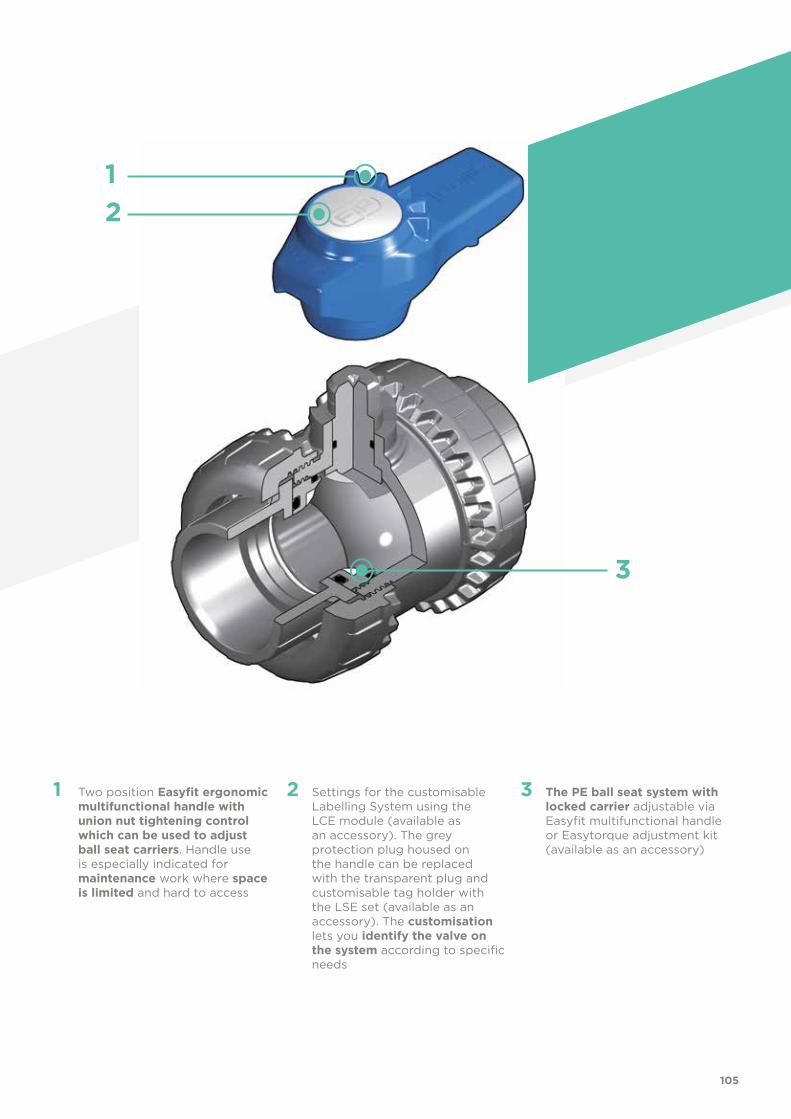
21
3
105
1 Two position Easyfit ergonomic multifunctional handle with union nut tightening control which can be used to adjust ball seat carriers. Handle use is especially indicated for maintenance work where space is limited and hard to access
2 Settings for the customisable Labelling System using the LCE module (available as an accessory). The grey protection plug housed on the handle can be replaced with the transparent plug and customisable tag holder with the LSE set (available as an accessory). The customisation lets you identify the valve on the system according to specific needs
3 The PE ball seat system with locked carrier adjustable via Easyfit multifunctional handle or Easytorque adjustment kit (available as an accessory)

106
TECHNICAL DATA
-40 -20 0 20 40 60 80 100 120 140 °C
16
14
12
10
8
6
4
2
0
Wo
rkin
g p
ress
ure
Working temperature
barPRESSURE VARIATION ACCORDING TO TEMPERATURE
For water and harmless fluids to which the material is classified as CHEMICALLY RESISTANT. In other cases, a reduction of the nominal PN pressure is required (25 years with safety factor).
The information in this leaflet is provided in good faith. No liability will be accepted concerning technical data that is not directly covered by recognised international standards. FIP reserves the right to carry out any modification. Products must be installed and maintained by qualified personnel.
PRESSURE DROP GRAPH
Pre
ssu
re d
rop
Flow Rate
bar1 10 100 1000 10000 l/min
1
0.1
0.01
0.001
DN
15
DN
10
DN
20
DN
25
DN
32
DN
40
DN
50
KV100 FLOW COEFFICIENTThe Kv100 flow coefficient is the Q flow rate of litres per minute of water at a temperature of 20°C that will generate ∆p= 1 bar pressure drop at a certain valve position.The Kv100 values shown in the table are calculated with the valve completely open.
DN 10 15 20 25 32 40 50
Kv100 l/min 80 200 385 770 1100 1750 3400

107
R DN PN B C C1 E H L Z g Code
3/8” 10 16 49 64 44 54 82 11.4 59.2 180 VEEFV038E
1/2” 15 16 49 64 44 54 90 15 60 175 VEEFV012E
3/4” 20 16 62 78 55 63 93 16.3 60.4 260 VEEFV034E
1” 25 16 71 87 60 72 110 19.1 71.8 365 VEEFV100E
1” 1/4 32 16 82 102 72 85 127 21.4 84.2 565 VEEFV114E
1” 1/2 40 16 92 109 76 100 131 21.4 88.2 795 VEEFV112E
2” 50 16 110 133 94 118 161 25.7 109.6 1325 VEEFV200E
DIMENSIONS
d DN PN B C C1 E H L Z g Code
16 10 16 49 64 44 54 82 14 54 180 VEEIV016E
20 15 16 49 64 44 54 82 16 50 175 VEEIV020E
25 20 16 62 78 55 63 91 19 53 260 VEEIV025E
32 25 16 71 87 60 72 103 22 59 365 VEEIV032E
40 32 16 82 102 72 85 120 26 68 565 VEEIV040E
50 40 16 92 109 76 100 139 31 77 795 VEEIV050E
63 50 16 110 133 94 118 174 38 98 1325 VEEIV063E
VEEIVEasyfit 2-way ball valve with female ends for solvent welding, metric series
VEEFVEasyfit 2-way ball valve with BSP threaded female ends
d DN PN B C C1 E H L Z g Code
1/2” 15 16 49 64 44 54 82 16.5 49 175 VEELV012E
3/4” 20 16 62 78 55 63 91 19 53 260 VEELV034E
1” 25 16 71 87 60 72 103 22.5 58 365 VEELV100E
1” 1/4 32 16 82 102 72 85 120 26 68 565 VEELV114E
1” 1/2 40 16 92 109 76 100 139 30 79 795 VEELV112E
2” 50 16 110 133 94 118 174 36 102 1325 VEELV200E
VEELVEasyfit 2-way ball valve with female ends for solvent welding, BS series

d DN PN B C C1 E H L Z g Code
1/2” 15 16 49 64 44 54 96 22.5 51 175 VEEAV012E
3/4” 20 16 62 78 55 63 105 25.5 54 260 VEEAV034E
1” 25 16 71 87 60 72 117 28.7 59.5 365 VEEAV100E
1” 1/4 32 16 82 102 72 85 136 32 72 565 VEEAV114E
1” 1/2 40 16 92 109 76 100 147 35 77 795 VEEAV112E
2” 50 16 110 133 94 118 174 38.2 97.6 1325 VEEAV200E
VEEAVEasyfit 2-way ball valve with female ends for solvent welding, ASTM series
R DN PN B C C1 E H L Z g Code
3/8” 10 16 49 64 44 54 82 13.7 54.6 180 VEENV038E
1/2” 15 16 49 64 44 54 90 17.8 54.4 175 VEENV012E
3/4” 20 16 62 78 55 63 93 18 57 260 VEENV034E
1” 25 16 71 87 60 72 110 22.6 64.8 365 VEENV100E
1” 1/4 32 16 82 102 72 85 127 25.1 76.8 565 VEENV114E
1” 1/2 40 16 92 109 76 100 131 24.7 81.6 795 VEENV112E
2” 50 16 110 133 94 118 161 29.6 101.8 1325 VEENV200E
VEENVEasyfit 2-way ball valve with female ends, NPT thread
d DN PN B C C1 E H L Z g Code
1/2” 15 16 49 64 44 54 110 30 50 195 VEEJV012E
3/4” 20 16 62 78 55 63 123 35 53 285 VEEJV034E
1” 25 16 71 87 60 72 139 40 59 395 VEEJV100E
1” 1/4 32 16 82 102 72 85 156 44 68 600 VEEJV114E
1” 1/2 40 16 92 109 76 100 187 55 77 835 VEEJV112E
2” 50 16 110 133 94 118 228 63 102 1375 VEEJV200E
VEEJVEasyfit 2-way ball valve with female ends for solvent welding, JIS series
108

R DN PN B C C1 E H L Z g Code
1/2” 15 16 49 64 44 54 82 16 50 175 VEEGV012E
3/4” 20 16 62 78 55 63 91 19 53 260 VEEGV034E
1” 25 16 71 87 60 72 103 22 59 365 VEEGV100E
1” 1/4 32 16 82 102 72 85 120 25 70 565 VEEGV114E
1” 1/2 40 16 92 109 76 100 139 26 87 795 VEEGV112E
2” 50 16 110 133 94 118 174 31 112 1325 VEEGV200E
VEEGVEasyfit 2-way ball valve with female ends, JIS thread
ACCESSORIES
DN R PN CH H L LT Z g Code
40 1” 1/2 16 52 196 21.4 63.4 153.2 795 CVRV112
50 2” 16 62 226 25.7 69.2 174.6 1325 CVRV200
CVRVThreaded male end connectors for ball valves
DN PN H P1 P2 g Code
40 16 246 50 52 840 CVPV050
50 16 273 60 64 1350 CVPV063
CVPVHose adaptor for ball valves
d DN PN L SDR Code
20 15 16 55 11 CVDE11020
25 20 16 70 11 CVDE11025
32 25 16 74 11 CVDE11032
40 32 16 78 11 CVDE11040
52 40 16 84 11 CVDE11050
63 50 16 91 11 CVDE11063
CVDELong spigot PE100 end connectors for joints with electrofusion fittings or for butt welding
109

LSE
LCE
Customisation and label printing set for Easyfit handle made up of precut adhesive sheets and software for guided label creation.
Transparent protection plug with tag holder
d DN Code
16 10 LSE020
20 15 LSE020
25 20 LSE025
32 25 LSE032
40 32 LSE040
50 40 LSE050
63 50 LSE063
d DN Code
16 10 LCE020
20 15 LCE020
25 20 LCE025
32 25 LCE032
40 32 LCE040
50 40 LCE050
63 50 LCE063
EASYTORQUE KITKit for union nut tightening adjustment and ball seat carrier for Easyfit DN 10÷50 valves.
d DN *Union nut tightening torque
*Seat carrier tightening torque Code
3/8”-1/2” 10-15 5 N m - 3,69 Lbf ft 3 N m - 2,21 Lbf ft KET01
3/4” 20 5 N m - 3,69 Lbf ft 3 N m - 2,21 Lbf ft KET01
1” 25 6 N m - 4,43 Lbf ft 4 N m - 2,95 Lbf ft KET01
1” 1/4 32 7 N m - 5,16 Lbf ft 4 N m - 2,95 Lbf ft KET01
1” 1/2 40 8 N m - 5,90 Lbf ft 5 N m - 3,69 Lbf ft KET01
2” 50 10 N m - 7,38 Lbf ft 6 N m - 4,43 Lbf ft KET01
*calculated in ideal installation conditions
110
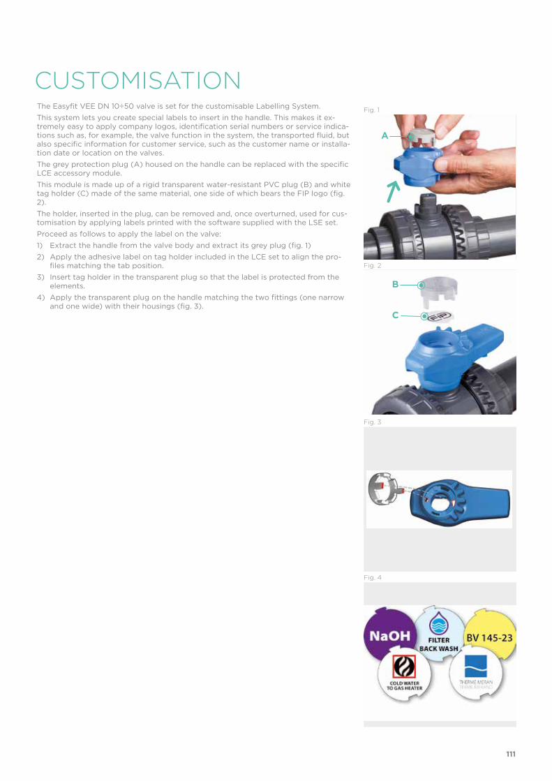
CUSTOMISATIONThe Easyfit VEE DN 10÷50 valve is set for the customisable Labelling System. This system lets you create special labels to insert in the handle. This makes it ex-tremely easy to apply company logos, identification serial numbers or service indica-tions such as, for example, the valve function in the system, the transported fluid, but also specific information for customer service, such as the customer name or installa-tion date or location on the valves.The grey protection plug (A) housed on the handle can be replaced with the specific LCE accessory module. This module is made up of a rigid transparent water-resistant PVC plug (B) and white tag holder (C) made of the same material, one side of which bears the FIP logo (fig. 2). The holder, inserted in the plug, can be removed and, once overturned, used for cus-tomisation by applying labels printed with the software supplied with the LSE set. Proceed as follows to apply the label on the valve:1) Extract the handle from the valve body and extract its grey plug (fig. 1)2) Apply the adhesive label on tag holder included in the LCE set to align the pro-
files matching the tab position.3) Insert tag holder in the transparent plug so that the label is protected from the
elements.4) Apply the transparent plug on the handle matching the two fittings (one narrow
and one wide) with their housings (fig. 3).
Fig. 1
Fig. 2
Fig. 4
Fig. 3
A
B
C
111

COMPONENTSEXPLODED VIEW
1 Handle plug (PVC-U - 1)2 Stem O-Ring
(EPDM - 2)*3 Stem (PVC-U - 1)4 Body (PVC-U - 1) 5 Ball (PVC-U - 1)
* Spare parts
The component material and quantity supplied are indicated in the parentheses.
6 Radial seal O-Ring (EPDM - 1)*7 End connector (PVC-U - 2)8 Ball seat carrier
(PVC-U - 1)9 Ball seat (PE - 2)
10 Socket seal O-Ring (EPDM - 2)*12 Handle (HIPVC - 1)13 Union nut (PVC-U - 2)
112

INSTALLATIONBefore proceeding with installation. please follow these instructions carefully:1) Check that the pipes to be connected to the valve are aligned in order to avoid
mechanical stress on the threaded joints.2) Unscrew the union nuts (13) and slide them onto the pipe.3) Solvent weld or screw the end connectors (7) onto the pipe segments.4) Position the valve between the end connectors (fig. 6). Warning: if a high pressure test is required, always position the body with the
"REGULAR" label upstream from the fluid direction.5) Fit the union nuts on the valve body and manually tighten clockwise until they be-
come hard to turn; do not use wrenches or other tools that can damage the union nut surfaces.
6) Extract the handle (12) from the valve body and extract its grey plug (1) (fig. 2)7) Overturn the handle and insert in on the valve stem matching the handle teeth (A)
with the union nut teeth (B) (fig. 9-10).8) Turn the handle counter-clockwise to fully tighten the union nut. The rotation
directions to tighten (TIGHTEN) and loosen (UNTIGHTEN) the union nuts are indi-cated on the handle (fig. 11). Generally, if pipes are not offset, one turn is sufficient for correct tightening.
DISMOUNTING ASSEMBLY1) Isolate the valve from the line (re-
lease the pressure and empty the pipeline).
2) Fully unscrew the union nuts (13) from the valve body and slide the body out sideways (fig. 5-6).
To do this, we recommend you use the Easyfit handle as a tool (fig. 9-10)
3) Before dismounting, hold the valve in a vertical position and open it 45° to drain any liquid that might remain.
4) After closing the valve, remove the handle (12) (fig. 7) and insert the two protrusions in the lower side in the two apertures and in the carrier pas-sage bore (8), extracting it by turning counter-clockwise (fig. 8).
5) Press on the ball from the side oppo-site the "REGULAR" label, being sure not to scratch it, until the ball seat carrier exits (8), then extract the ball (5).
6) Press the stem (3) inwards until it ex-its the body.
7) Remove the O-Rings (2, 6, 10) and ball seats (9) extracting them from their seats, as illustrated in the ex-ploded view.
1) All the O-Rings (2, 6, 10) must be in-serted in their grooves as shown in the exploded view.
2) Insert the stem (3) from inside the body (4).
3) Place the ball seats (9) in the housings in the body (4) and in the carrier (8).
4) Insert the ball (5) rotating it to the closed position.
5) Screw the carrier (8) into the body and tighten up in the clockwise direction us-ing the handle (12) to limit stop.
6) Position the valve between the end con-nectors (7) and tighten the union nuts (13) clockwise using the Easyfit multi-functional handle, being sure the socket seal O-Rings (10) do not exit the seats.
7) Position the handle (12) on the stem (3).
Fig. 8
Fig. 7
Note: during assembly operations, it is advisable to lubricate the rubber seals. Mineral oils are not recommended for this task as they react aggressively with EPDM rubber.
Fig. 5
Fig. 6
113

WARNINGS
9) Repeat point 7 for the other union nut. Note: A small force applied on the handle develops a torque much higher than
manual tightening. You can also, using the Easytorque kit (fig. 12), supplied as an accessory, tighten
union nuts using a torque wrench to quantify the force and thus monitor the stress applied to the thermoplastic threads according to the installation indica-tions in the instructions enclosed with the kit.
10) Apply the plug (1) on the handle (12) matching the two fittings (one narrow and one wide) with the relevant housings on the handle (fig. 3).
11) Install the handle (12) on the stem (3) again.12) If necessary, support the pipe with FIP pipe clip model ZIKM and DSM distance
plates.
- If volatile liquid such as Hydrogen Peroxide (H2O2) or Sodium Hypochlorite (NaCIO) is used, for safety reasons we recommend you contact the service centre. These liquids, upon vaporising, could create hazardous over pressures in the area between the body and ball.
- Do not use compressed air or other gases to test thermoplastic lines.- Always avoid sudden closing manoeuvres and protect the valve from accidental
manoeuvres.
Fig. 9
Fig. 10
Fig. 11
Fig. 12
A
B
114


VEE DN 65÷100PVC-U
Easyfit 2-way ball valve

118
VEE
EASYFIT 2-WAY BALL VALVE
• Patented Easyfit system: innovative mechanism that lets you use the quick release handle to adjust the ball carrier
• Connection system for solvent weld and threaded joints• Valve material compatibility (PVC-U) with water, drinking ware and other
food substances according to current regulations• Easy radial dismounting allowing quick replacement of O-rings and ball
seats without any need for tools • PN16 True Union valve body made for PVC-U injection moulding and Eu-
ropean Directive 97/23/EC compliant for PED pressurised equipment. ISO 9393 compliant test requirements
• Valve body with built-in anchoring frame for the special Power Quick Easyfit module dedicated to the installation of pneumatic and electric actuators or accessories
• Option of dismounting downstream pipes with the valve in the closed position
• Floating full bore ball with high surface finish made in CNC work stations to achieve precise dimensional tolerance and high surface finish
DN 65÷100FIP and Giugiaro Design designed anddeveloped VEE Easyfit, the innovative True Union ball valve that permits simple and safe installation for reliable service over time.
Technical specificationsConstruction Easyfit 2-way True Union ball valve with locked
carrierSize range DN 65 ÷ 100Nominal pressure PN 16 with water at 20 °CTemperature range 0 °C ÷ 60 °CCoupling standards Solvent welding: EN ISO 1452, EN ISO 15493, BS 4346/1,
DIN 8063, NF T54-028, ASTM D 2467, JIS K 6743. Pipe coupling capacity according to EN ISO 1452, EN ISO 15493, DIN 8062, NF T54-016, ASTM D 1785, JIS K 6741
Thread: ISO 228-1, DIN 2999, ASTM D 2467, JIS B 0203
Reference standards Construction criteria: EN ISO 16135, EN ISO 1452, EN ISO 15493Test methods and requirements: ISO 9393Installation criteria: DVS 2204, DVS 2221, UNI 11242Actuator couplings: ISO 5211
Valve material PVC-USeal material EPDM (standard size O-Ring);
PE (ball seats)
Control options Manual control

1
2
5
4
3
119
1 Innovative quick release Easyfit handle made up of a central hub firmly coupled with the stem by a dual spoke grip that can be released from the hub with a simple operation and used as a ball seat adjustment tool
2 Settings for the customisable Labelling System using the LCE module (available as an accessory). The grey protection plug housed on the central hub can be replaced with the transparent plug and customisable tag holder with
the LSE set (available as an accessory). The customisation lets you identify the valve on the system according to specific needs
3 PE seal system with locked carrier adjustable via the Easyfit quick release handle
4 Stem with high surface finish and double O-Ring and PTFE anti-friction disk that limits friction to a minimum and grants excellent operating torque
5 Valve body set for SHE kit installation (available as an accessory) that blocks the closing and opening manoeuvres with a lock

120
TECHNICAL DATA
-40 -20 0 20 40 60 80 100 120 140 °C
16
14
12
10
8
6
4
2
0
Wo
rkin
g p
ress
ure
Working temperature
barPRESSURE VARIATION ACCORDING TO TEMPERATURE
For water and harmless fluids to which the material is classified as CHEMICALLY RESISTANT. In other cases, a reduction of the nominal PN pressure is required (25 years with safety factor).
KV100 FLOW COEFFICIENTThe Kv100 flow coefficient is the Q flow rate of litres per minute of water at a temperature of 20°C that will generate ∆p= 1 bar pressure drop at a certain valve position.The Kv100 values shown in the table are calculated with the valve completely open.
PRESSURE DROP GRAPH
Pre
ssu
re d
rop
Flow Rate
bar1 10 100 1000 10000 l/min
1
0.1
0.01
0.001
DN
65
DN
80
DN
100
DN 65 80 100
Kv100 l/min 5000 7000 9400

121
The information in this leaflet is provided in good faith. No liability will be accepted concerning technical data that is not directly covered by recognised international standards. FIP reserves the right to carry out any modification. Products must be installed and maintained by qualified personnel.
OPERATING TORQUE AT MAXIMUM WORKING RPESSURE
Nm 65 80 100 65 80 100 65 80 100 DN
70
60
50
40
30
20
10
0
Op
erat
ing
to
rqu
e
PN 6 PN 10 PN 16

R DN PN B C C1 E H L Z g Code
2” 1/2 65 16 142 214 115 157 211 30.2 150.6 2750 VEEFV212E
3” 80 16 151 239 126 174 248 33.3 181.4 3432 VEEFV300E
4” 100 16 174.5 270 145 212 283 39.3 204.4 5814 VEEFV400E
d DN PN B C C1 E H L Z g Code
2” 1/2 65 16 142 214 115 157 211 44 123 2750 VEELV212E
3” 80 16 151 239 126 174 248 51 146 3432 VEELV300E
4” 100 16 174.5 270 145 212 283 63 157 5814 VEELV400E
d DN PN B C C1 E H L Z g Code
75 65 16 142 214 115 157 211 44 123 2750 VEEIV075E
90 80 16 151 239 126 174 248 51 146 3432 VEEIV090E
110 100 16 174.5 270 145 212 283 61 161 5814 VEEIV110E
VEEIVEasyfit 2-way ball valve with female ends for solvent welding, metric series
VEEFVEasyfit 2-way ball valve with BSP threaded female ends
VEELVEasyfit 2-way ball valve with female ends, BS series
VEEAVEasyfit 2-way ball valve with female ends, ASTM series
d DN PN B C C1 E H L Z g Code
2” 1/2 65 16 142 214 115 157 211 44.5 122 2750 VEEAV212E
3” 80 16 151 239 126 174 248 48 152 3432 VEEAV300E
4” 100 16 174.5 270 145 212 283 57.5 168 5814 VEEAV400E
122
DIMENSIONS

R DN PN B C C1 E H L Z g Code
2” 1/2 65 16 142 214 115 157 211 35 141 2750 VEEGV212E
3” 80 16 151 239 126 174 248 40 168 3432 VEEGV300E
4” 100 16 174.5 270 145 212 283 45 193 5814 VEEGV400E
d DN PN B C C1 E H L Z g Code
75 65 16 141.5 214 115 157 331 71 189 2286 VEEBEV075E
90 80 10 151 239 126 174 367 88 191 3059 VEEBEV090E
110 100 10 174.5 270 145 212 407 92 223 5814 VEEBEV110E
VEENVEasyfit 2-way ball valve with female ends, NPT thread
VEEGVEasyfit 2-way ball valve with female ends, JIS thread
VEEBEVEasyfit 2-way ball valve with PE100 SDR 11 male end connectors for butt welding or electrofusion (CVDE)
VEEJVEasyfit 2-way ball valve with female ends, JIS series
R DN PN B C C1 E H L Z g Code
2” 1/2 65 16 142 214 115 157 211 33.2 144.6 2750 VEENV212E
3” 80 16 151 239 126 174 248 35.5 177 3432 VEENV300E
4” 100 16 174.5 270 145 212 283 37.6 207.8 5814 VEENV400E
d DN PN B C C1 E H L Z g Code
2” 1/2 65 16 142 214 115 157 243 61 121 2750 VEEJV212E
3” 80 16 151 239 126 174 272 64.5 143 3432 VEEJV300E
4” 100 16 174.5 270 145 212 332 84 164 5814 VEEJV400E
123

LSE
LCE
Customisation and label printing set for Easyfit handle made up of precut adhesive sheets and software for guided label creation.
Transparent protection plug with tag holder
d inch DN A A1 B B min CodeISO pipe
CodeASTM-BS pipe
75 2” 1/2 65 76 63 159 364 PSE090 PSE300
90 3” 80 76 63 166 371 PSE090 PSE300
110 4” 100 76 63 186 433 PSE110 PSE400
PSEStem extension
d DN Code
75 65 LSE040
90 80 LSE040
110 100 LSE040
d DN Code
75 65 LCE040
90 80 LCE040
110 100 LCE040
ACCESSORIES
d DN PN L SDR Code
75 65 16 111 11 CVDE11075
90 80 16 118 11 CVDE11090VXE
110 100 16 127 11 CVDE11110VXE
CVDELong spigot PE100 end connectors for joints with electrofusion fittings or for butt welding
124

POWER QUICK EASYFITThe valve can be equipped with pneumatic or electric standard actuators and gearboxfor heavy-duty operations, using the PP-GR module reproducing the drilling pattern foreseen by ISO 5211.
d DN B2 Q T p x j P x J Code
75 65 129 14 16 F05 x 6,5 F07 x 8,5 PQE090
90 80 136 14 16 F05 x 6,5 F07 x 8,5 PQE090
110 100 156 17 19 F05 x 6,5 F07 x 8,5 PQE110
Switch type Flow Rate Lifetime[drives]
Operating voltage
Nominal voltage
Working pressure Voltage drop No-load sup-
ply currentProtection
rate
Electromechanical 250 V - 5 A 3 x 10⁷ - - - - - IP65
Inductive - - 5 ÷ 36 V - 4 ÷ 200 mA < 4,6 V < 0,8 mA IP65
Namur* - - 7,5 ÷ 30 V DC** 8,2 V DC < 30 mA** - - IP65
* To be used with an amplifier** Outside areas with explosion risks
Electromechanical Inductive Namur
WH = white; BK = black; BL = blue; BR = brown
MSEMSE is a limit switch box with electromechanical or inductive micro switches to remote-ly signal the valve position. Manual valve installation is possible using the Power Quick Easyfit actuation module.The box can be assembled on the VEE valve even if already installed on the system.
d DN A B B1Code
electromechanicalCode
inductiveCode
Namur
75 65 139 203 79 MSE1M MSE1I MSE1N
90 80 146 210 87 MSE1M MSE1I MSE1N
110 100 166 231 106 MSE2M MSE2I MSE2N
SHEAnti-tampering lock kit
d DN Code
75 65 SHE090
90 80 SHE090
110 100 SHE110
125

CUSTOMISATIONThe Easyfit VEE DN 65÷100 valve is set for the customisable Labelling System. This system lets you create special labels to insert in the handle. This makes it ex-tremely easy to apply company logos, identification serial numbers or service indica-tions such as, for example, the valve function in the system, the transported fluid, but also specific information for customer service, such as the customer name or installa-tion date or location on the valves. The grey protection plug (A) housed on the handle can be replaced with the specific LCE accessory module. This module is made up of a rigid transparent water-resistant PVC plug (B) and white tag holder (C) made of the same material, one side of which bears the FIP logo (fig. 2). The holder, inserted in the plug, can be removed and, once overturned, used for cus-tomisation by applying labels printed with the software supplied with the LSE set.Proceed as follows to apply the label on the valve:1) Release the handle from the central hub (D) and extract the grey plug (fig. 1).2) Apply the adhesive label on tag holder included in the LCE set to align the pro-
files matching the tab position.3) Insert tag holder in the transparent plug so that the label is protected from the
elements (fig. 3).4) Apply the transparent plug on the central hub matching the two fittings (one nar-
row and one wide) with the relevant housings.
Fig. 2
Fig. 1
Fig. 3
Fig. 4
CD
B
A
126

COMPONENTSEXPLODED VIEW
2 Easyfit quick release handle (HIPVC - 1)3 Stem O-Ring (EPDM - 2)*4 Stem (PVC-U - 1) 5 Ball seat (PE - 2)*6 Ball (PVC-U - 1)*
* Spare parts
The component material and quantity supplied are indicated in the parentheses.
7 Body (PVC-U - 1)8 Ball seat O-Ring
(EPDM, FPM - 2)9 Radial seal O-Ring (EPDM - 1)*10 Socket seal O-Ring (EPDM - 2)*11 Ball seat carrier
(PVC-U - 1)12 End connector (PVC-U - 2)
13 Union nut (PVC-U - 2)14 Grey protection plug (PVC - 1)15 Central hub (HIPVC - 1)16 Anti-friction disk (PTFE - 1)*
127

INSTALLATIONBefore proceeding with installation. please follow these instructions carefully:1) Check that the pipes to be connected to the valve are aligned in order to avoid
mechanical stress on the threaded joints.2) Unscrew the union nuts (13) from the body (7) and insert them in the pipe seg-
ments.3) Solvent weld or screw the end connectors (12) onto the pipe segments.4) Position the valve between the end connectors (fig. 8). Warning: if a high pressure test is required, always position the body with the
"REGULAR" label upstream from the fluid direction.5) Fit the union nuts on the valve body and tighten clockwise (fig. 7).
DISMOUNTING ASSEMBLY1) Isolate the valve from the line (re-
lease the pressure and empty the pipeline).
2) Fully unscrew the union nuts (13) from the valve body and slide the body out sideways (7) (fig. 7-8).
3) Before dismounting, hold the valve in a vertical position and open it 45° to drain any liquid that might remain.
4) Open the valve.5) Remove the ball seat carrier (11) us-
ing the Easyfit quick release handle (2). Extract the handle from the central hub (15) pushing towards the hub hinge centres (fig. 5-6). Insert the two protrusion at the top of the handle in the carrier seats (11) and unscrew, extracting it by turning counter-clockwise (fig. 9-10).
6) Press on the ball (6) from the side opposite the "REGULAR" label, being sure not to scratch it, until the ball seat exits (11) then extract the ball (6).
7) Remove the central hub (15) firmly sliding it off the stem (4). Press the stem inwards and extract it from the body and remove the anti-friction disk (16).
8) Remove the O-Ring (3, 8, 9, 10) and ball seats (5) extracting them from their seats, as illustrated in the ex-ploded view.
1) All the O-rings (3, 8, 9, 10) must be inserted in their grooves as shown in the exploded view.
2) Place the anti-friction disk (16) on the stem (4) and insert it in the body (7).
3) Place the ball seats (5) in the hous-ings in the body (7) and in the carrier (11).
4) Insert the ball (6) rotating it to the closed position.
5) Screw the carrier (11) into the body and tighten up in the clockwise direc-tion using the handle (2) to limit stop.
6) Place the central hub (15) on the stem (4) firmly pressing down to match the internal hub key with one of the two seats on the stem.
7) Position the valve between the end connectors (12) and tighten the union nuts (13) clockwise making sure the socket seal O-Rings (10) do not exit the seats (fig. 7-8).
8) Reposition the handle (2) on the central hub (15) making sure the two grooves in the central handle bore match the two grooves on the side of the hub and slightly press down until the two hinges click.
Fig. 6
Fig. 5
Note: during assembly operations, it is advisable to lubricate the rubber seals. Mineral oils are not recommended for this task as they react aggressively with EPDM rubber.
Fig. 7
Fig. 8
128
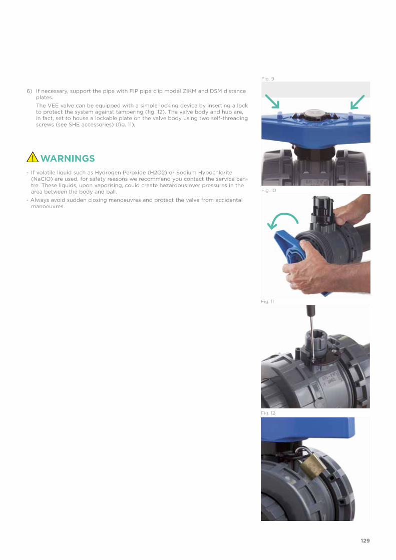
Fig. 9
Fig. 10
6) If necessary, support the pipe with FIP pipe clip model ZIKM and DSM distance plates.
The VEE valve can be equipped with a simple locking device by inserting a lock to protect the system against tampering (fig. 12). The valve body and hub are, in fact, set to house a lockable plate on the valve body using two self-threading screws (see SHE accessories) (fig. 11),
WARNINGS- If volatile liquid such as Hydrogen Peroxide (H2O2) or Sodium Hypochlorite
(NaCIO) are used, for safety reasons we recommend you contact the service cen-tre. These liquids, upon vaporising, could create hazardous over pressures in the area between the body and ball.
- Always avoid sudden closing manoeuvres and protect the valve from accidental manoeuvres.
Fig. 11
Fig. 12
129


SXE-SSE DN 10÷50PVC-U
Easyfit True Union ball and spring check valve

132
Technical specificationsConstruction SXE: Easyfit True Union ball check valve with locked
carrier SSE: Easyfit True Union spring check valve
Size range DN 10 ÷ 50Nominal pressure PN 16 with water at 20 °CTemperature range 0 °C ÷ 60 °CCoupling standards Solvent welding: EN ISO 1452, EN ISO 15493, BS 4346-1,
DIN 8063, NF T54-028, ASTM D 2467, JIS K 6743. Pipe coupling capacity according to EN ISO 1452, EN ISO 15493, DIN 8062, NF T54-016, ASTM D 1785, JIS K 6741
Thread: ISO 228-1, DIN 2999, ASTM D 2464, JIS B 0203
Reference standards Construction criteria: EN ISO 16137, EN ISO 1452, EN ISO 15493Test methods and requirements: ISO 9393Installation criteria: DVS 2204, DVS 2221, UNI 11242
Valve material PVC-USeal material EPDM, FPM Spring material (SSE) Available in STAINLESS steel 316, Hastelloy C276,
A316 PTFE encapsulated (DN 40 and DN 50 only)
SXE-SSE
The Easyfit check valve line developed with Giugiaro Design offers two different versions: SXE with ball shutter and SSE with spring loaded shutter. Easyfit check valves stand out for the innovative installation method that guarantees reliable service over time.This valve is also equipped with the customisable Labelling System.
EASYFIT TRUE UNION BALL AND SPRING CHECK VALVE• Connection system for solvent weld and threaded joints• Valve material compatibility (PVC-U) with water conveyance, drinking
water and other food substances according to current regulations• PN16 True Union valve body made for PVC-U injection moulding and
compliant with European Directive 97/23/EC for PED pressurised equip-ment. Test requirements compliant with ISO 9393
• Short face to face dimension according to international regulation ISO 7508 series III and European regulation EN 1452 ”short” and fully inter-changeable with VXE and VEE DN 10÷50 ball valve models
• Union nuts with rack for tightening adjustment via Easyfit handle or via Easytorque adjustment kit (available as accessories)
• Vertical (preferable for SXE model) and horizontal installation potential
DN 10÷50

133
1 Customisable Labelling System: built-in LCE module on the valve body made up of transparent protection plug and customisable tag holder using the LSE set (available as accessory). The customisation potential lets you identify the valve on the system according to specific needs
2 Optimised dynamic fluid design: energy savings thanks to the improved valve Kv value with consequent pressure drop reduction
3 High surface finish ball shutter: wear reduction, increase in working life and reduced valve maintenance. Ideal for conveying dirty fluids, even with suspended solids and filaments thanks to the special design that permits internal valve self-cleaning
4 Locked ball seat carrier: safe dismounting for maintenance with the Easyfit multifunctional handle or Easytorque kit
5 Ideal for horizontal installations: perfect seal even with low back pressure.
Silent and durable even with strong vibrations and pulsating fluid
6 PVC-U shutter and springs available made of STAINLESS steel 316, Hastelloy C276, A316 PTFE encapsulated: maximum reliability in a wide field of applications from salt water to aggressive acids
SSE
6
5
SXE
2
3
41

134
-40 -20 0 20 40 60 80 100 120 140 °C
16
14
12
10
8
6
4
2
0
bar
TECHNICAL DATA
Wo
rkin
g p
ress
ure
Working temperature
PRESSURE VARIATION ACCORDING TO TEMPERATURE
For water and harmless fluids to which the material is classified as CHEMICALLY RESISTANT. In other cases, a reduction of the nominal PN pressure is required (25 years with safety factor).
PRESSURE DROP GRAPH
Pre
ssu
re d
rop
Flow Rate
KV100 FLOW COEFFICIENTThe Kv100 flow coefficient is the Q flow rate of litres per minute of water at a temperature of 20°C that will generate ∆p= 1 bar pressure drop at a certain valve position.The Kv100 values shown in the table are calculated with the SXE valve completely open.
bar1 10 100 1000 10000 l/min
1
0,1
0,01
0,001
DN
15D
N 10
DN
20
DN
25
DN
32
DN
40
DN
50
DN 10 15 20 25 32 40 50
Kv100 l/min 172 152 258 433 643 928 1343

135
The information in this leaflet is provided in good faith. No liability will be accepted concerning technical data that is not directly covered by recognised international standards. FIP reserves the right to carry out any modification. Products must be installed and maintained by qualified personnel.
MINIMUM VALVE SEALING PRESSURE
The PVC-U SXE valve can only be used with liquids with specific weight under 1.37g/cm3.
DN 10 15 20 25 32 40 50
SXE (bar) 0,2 0,2 0,2 0,2 0,2 0,2 0,2
SSE (bar) 0,08 0,08 0,08 0,08 0,08 0,08 0,08

136
DIMENSIONS
d DN PN E H L Z g EPDM Code FPM Code
16 10 16 54 82 14 54 145 SXEIV016E SXEIV016F
20 15 16 54 82 16 50 148 SXEIV020E SXEIV020F
25 20 16 63 91 19 53 190 SXEIV025E SXEIV025F
32 25 16 72 103 22 59 300 SXEIV032E SXEIV032F
40 32 16 85 120 26 68 460 SXEIV040E SXEIV040F
50 40 16 100 139 31 77 675 SXEIV050E SXEIV050F
63 50 16 118 174 38 98 1080 SXEIV063E SXEIV063F
SXEIVEasyfit ball check valve with female ends for solvent welding, metric series
R DN PN E H L Z g EPDM Code FPM Code
3/8” 10 16 54 82 11.4 59.2 145 SXEFV038E SXEFV038F
1/2” 15 16 54 90 15 60 148 SXEFV012E SXEFV012F
3/4” 20 16 63 93 16.3 60.4 190 SXEFV034E SXEFV034F
1” 25 16 72 110 19.1 71.8 300 SXEFV100E SXEFV100F
1” 1/4 32 16 85 127 21.4 84.2 460 SXEFV114E SXEFV114F
1” 1/2 40 16 100 131 21.4 88.2 675 SXEFV112E SXEFV112F
2” 50 16 118 161 25.7 109.6 1080 SXEFV200E SXEFV200F
SXEFVEasyfit ball check valve with BSP threaded female ends
d DN PN E H L Z g EPDM Code FPM Code
1/2” 15 16 54 82 16.5 49 148 SXELV012E SXELV012F
3/4” 20 16 63 91 19 53 190 SXELV034E SXELV034F
1” 25 16 72 103 22.5 58 300 SXELV100E SXELV100F
1” 1/4 32 16 85 120 26 68 460 SXELV114E SXELV114F
1” 1/2 40 16 100 139 30 79 675 SXELV112E SXELV112F
2” 50 16 118 174 36 102 1080 SXELV200E SXELV200F
SXELVEasyfit ball check valve with female ends for solvent welding, BS series

137
d DN PN E H L Z g EPDM Code FPM Code
1/2” 15 16 54 96 22.5 51 148 SXEAV012E SXEAV012F
3/4” 20 16 63 105 25.5 54 190 SXEAV034E SXEAV034F
1” 25 16 72 117 28.7 59.5 300 SXEAV100E SXEAV100F
1” 1/4 32 16 85 136 32 72 460 SXEAV114E SXEAV114F
1” 1/2 40 16 100 147 35 77 675 SXEAV112E SXEAV112F
2” 50 16 118 174 38.2 97.6 1080 SXEAV200E SXEAV200F
SXEAVEasyfit ball check valve with female ends for solvent welding, ASTM series
R DN PN E H L Z g EPDM Code FPM Code
3/8” 10 16 54 82 13.7 54.6 145 SXENV038E SXENV038F
1/2” 15 16 54 90 17.8 54.4 148 SXENV012E SXENV012F
3/4” 20 16 63 93 18 57 190 SXENV034E SXENV034F
1” 25 16 72 110 22.6 64.8 300 SXENV100E SXENV100F
1” 1/4 32 16 85 127 25.1 76.8 460 SXENV114E SXENV114F
1” 1/2 40 16 100 131 24.7 81.6 675 SXENV112E SXENV112F
2” 50 16 118 161 29.6 101.8 1080 SXENV200E SXENV200F
SXENVEasyfit ball check valve with female ends, NPT thread
d DN PN E H L Z g EPDM Code FPM Code
1/2” 15 16 54 110 30 50 160 SXEJV012E SXEJV012F
3/4” 20 16 63 123 35 53 235 SXEJV034E SXEJV034F
1” 25 16 72 139 40 59 325 SXEJV100E SXEJV100F
1” 1/4 32 16 85 156 44 68 490 SXEJV114E SXEJV114F
1” 1/2 40 16 100 187 55 77 680 SXEJV112E SXEJV112F
2” 50 16 118 228 63 102 1150 SXEJV200E SXEJV200F
SXEJVEasyfit ball check valve with female ends for solvent welding, JIS series

138
d DN E H L Z g EPDM Code FPM Code
20 15 54 154 41 72 150 SXEBEV020E SXEBEV020F
25 20 63 186 52 82 225 SXEBEV025E SXEBEV025F
32 25 72 199 54.5 90 310 SXEBEV032E SXEBEV032F
40 32 85 217 56 105 485 SXEBEV040E SXEBEV040F
50 40 100 236 58 120 700 SXEBEV050E SXEBEV050F
63 50 118 268 66 136 1150 SXEBEV063E SXEBEV063F
SXEBEVEasyfit ball check valve with PE100 SDR 11 male ends for butt welding or electrofusion welding (CVDE)
R DN PN E H L Z g EPDM Code FPM Code
1/2” 15 16 54 82 16 50 148 SXEGV012E SXEGV012F
3/4” 20 16 63 91 19 53 190 SXEGV034E SXEGV034F
1” 25 16 72 103 22 59 300 SXEGV100E SXEGV100F
1” 1/4 32 16 85 120 25 70 460 SXEGV114E SXEGV114F
1” 1/2 40 16 100 139 26 87 675 SXEGV112E SXEGV112F
2” 50 16 118 174 31 112 1080 SXEGV200E SXEGV200F
SXEGVEasyfit ball check valve with female ends, JIS thread

139
d DN PN E H L Z g EPDM Code FPM Code
16 10 16 54 82 14 54 146 SSEIV016E SSEIV016F
20 15 16 54 82 16 50 149 SSEIV020E SSEIV020F
25 20 16 63 91 19 53 188 SSEIV025E SSEIV025F
32 25 16 72 103 22 59 292 SSEIV032E SSEIV032F
40 32 16 85 120 26 68 445 SSEIV040E SSEIV040F
50 40 16 100 139 31 77 640 SSEIV050E SSEIV050F
63 50 16 118 174 38 98 1010 SSEIV063E SSEIV063F
SSEIVEasyfit spring check valve with female ends for solvent welding, metric series
R DN PN E H L Z g EPDM Code FPM Code
3/8” 10 16 54 82 11.4 59.2 146 SSEFV038E SSEFV038F
1/2” 15 16 54 90 15 60 149 SSEFV012E SSEFV012F
3/4” 20 16 63 93 16.3 60.4 188 SSEFV034E SSEFV034F
1” 25 16 72 110 19.1 71.8 292 SSEFV100E SSEFV100F
1” 1/4 32 16 85 127 21.4 84.2 445 SSEFV114E SSEFV114F
1” 1/2 40 16 100 131 21.4 88.2 640 SSEFV112E SSEFV112F
2” 50 16 118 161 25.7 109.6 1010 SSEFV200E SSEFV200F
SSEFVEasyfit spring check valve with BSP threaded female ends
d DN PN E H L Z g EPDM Code FPM Code
1/2” 15 16 54 82 16.5 49 149 SSELV012E SSELV012F
3/4” 20 16 63 91 19 53 188 SSELV034E SSELV034F
1” 25 16 72 103 22.5 58 292 SSELV100E SSELV100F
1” 1/4 32 16 85 120 26 68 445 SSELV114E SSELV114F
1” 1/2 40 16 100 139 30 79 640 SSELV112E SSELV112F
2” 50 16 118 174 36 102 1010 SSELV200E SSELV200F
SSELVEasyfit spring check valve with female ends for solvent welding, BS series
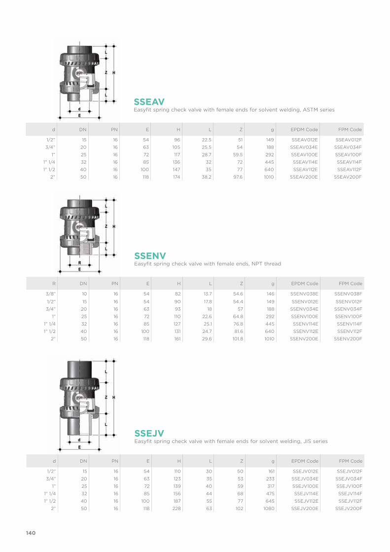
140
R DN PN E H L Z g EPDM Code FPM Code
3/8” 10 16 54 82 13.7 54.6 146 SSENV038E SSENV038F
1/2” 15 16 54 90 17.8 54.4 149 SSENV012E SSENV012F
3/4” 20 16 63 93 18 57 188 SSENV034E SSENV034F
1” 25 16 72 110 22.6 64.8 292 SSENV100E SSENV100F
1” 1/4 32 16 85 127 25.1 76.8 445 SSENV114E SSENV114F
1” 1/2 40 16 100 131 24.7 81.6 640 SSENV112E SSENV112F
2” 50 16 118 161 29.6 101.8 1010 SSENV200E SSENV200F
SSENVEasyfit spring check valve with female ends, NPT thread
d DN PN E H L Z g EPDM Code FPM Code
1/2” 15 16 54 110 30 50 161 SSEJV012E SSEJV012F
3/4” 20 16 63 123 35 53 233 SSEJV034E SSEJV034F
1” 25 16 72 139 40 59 317 SSEJV100E SSEJV100F
1” 1/4 32 16 85 156 44 68 475 SSEJV114E SSEJV114F
1” 1/2 40 16 100 187 55 77 645 SSEJV112E SSEJV112F
2” 50 16 118 228 63 102 1080 SSEJV200E SSEJV200F
SSEJVEasyfit spring check valve with female ends for solvent welding, JIS series
d DN PN E H L Z g EPDM Code FPM Code
1/2” 15 16 54 96 22.5 51 149 SSEAV012E SSEAV012F
3/4” 20 16 63 105 25.5 54 188 SSEAV034E SSEAV034F
1” 25 16 72 117 28.7 59.5 292 SSEAV100E SSEAV100F
1” 1/4 32 16 85 136 32 72 445 SSEAV114E SSEAV114F
1” 1/2 40 16 100 147 35 77 640 SSEAV112E SSEAV112F
2” 50 16 118 174 38.2 97.6 1010 SSEAV200E SSEAV200F
SSEAVEasyfit spring check valve with female ends for solvent welding, ASTM series
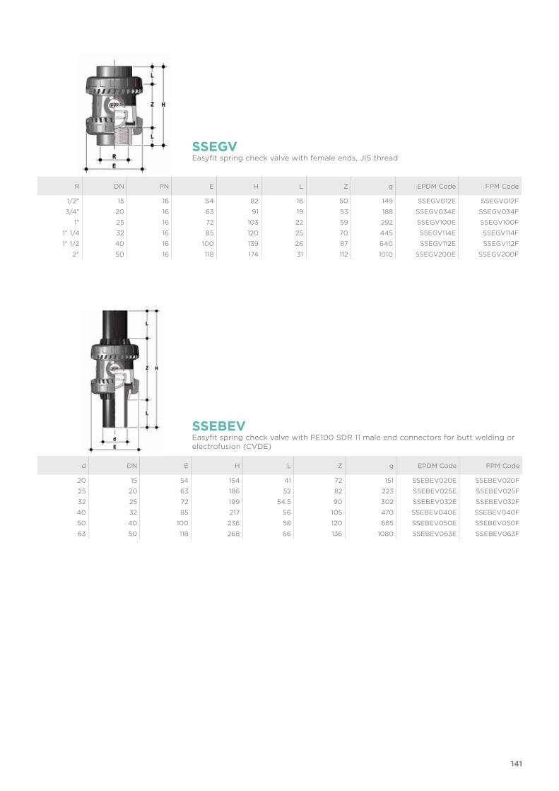
141
d DN E H L Z g EPDM Code FPM Code
20 15 54 154 41 72 151 SSEBEV020E SSEBEV020F
25 20 63 186 52 82 223 SSEBEV025E SSEBEV025F
32 25 72 199 54.5 90 302 SSEBEV032E SSEBEV032F
40 32 85 217 56 105 470 SSEBEV040E SSEBEV040F
50 40 100 236 58 120 665 SSEBEV050E SSEBEV050F
63 50 118 268 66 136 1080 SSEBEV063E SSEBEV063F
SSEBEVEasyfit spring check valve with PE100 SDR 11 male end connectors for butt welding or electrofusion (CVDE)
R DN PN E H L Z g EPDM Code FPM Code
1/2” 15 16 54 82 16 50 149 SSEGV012E SSEGV012F
3/4” 20 16 63 91 19 53 188 SSEGV034E SSEGV034F
1” 25 16 72 103 22 59 292 SSEGV100E SSEGV100F
1” 1/4 32 16 85 120 25 70 445 SSEGV114E SSEGV114F
1” 1/2 40 16 100 139 26 87 640 SSEGV112E SSEGV112F
2” 50 16 118 174 31 112 1010 SSEGV200E SSEGV200F
SSEGVEasyfit spring check valve with female ends, JIS thread

d DN PN L SDR Code
20 15 16 55 11 CVDE11020
25 20 16 70 11 CVDE11025
32 25 16 74 11 CVDE11032
40 32 16 78 11 CVDE11040
52 40 16 84 11 CVDE11050
63 50 16 91 11 CVDE11063
CVDELong spigot PE100 end connectors for joints with electrofusion fittings or for butt welding
d DN Code
16 - 20 10 - 15 HAVXE020
25 20 HAVXE025
32 25 HAVXE032
40 32 HAVXE040
52 40 HAVXE050
63 50 HAVXE063
EASYFIT HANDLE DN 10÷50Easyfit multifunctional handle for union nut tightening SXE-SSE DN 10÷50
EASYTORQUE KITKit for union nut tightening adjustment and ball seat carrier for Easyfit DN 10÷50 valves.
d DN Union nuts tightening torque*
Seat carrier tightening torque* Code
3/8”-1/2” 10-15 5 N m - 3,69 Lbf ft 3 N m - 2,21 Lbf ft KET01
3/4” 20 5 N m - 3,69 Lbf ft 3 N m - 2,21 Lbf ft KET01
1” 25 6 N m - 4,43 Lbf ft 4 N m - 2,95 Lbf ft KET01
1” 1/4 32 7 N m - 5,16 Lbf ft 4 N m - 2,95 Lbf ft KET01
1” 1/2 40 8 N m - 5,90 Lbf ft 5 N m - 3,69 Lbf ft KET01
2” 50 10 N m - 7,38 Lbf ft 6 N m - 4,43 Lbf ft KET01
*calculated in ideal installation conditions
142
ACCESSORIES

CUSTOMISATIONSXE and SSE DN 10÷50 Easyfit valves are equipped with a customisable Labelling System. This system lets you create special labels to affix to the valve body. This makes it extremely easy to apply company logos, identification serial numbers or service indications such as, for example, the valve function in the system, the transported fluid, but also specific information for customer service, such as the customer name or installation date or location on the valves.The specific LCE module is a standard supply and is made up of a rigid transparent water-resistant PVC plug and white tag holder made of the same material, one side of which bears the FIP logo (fig. 1). The holder, inserted in the plug, can be removed and, once overturned, used for cus-tomisation by applying labels printed with the software supplied with the LSE set.Proceed as follows to apply the label on the valve:1) Extract the transparent plug from the seat on the valve body (fig. 1).2) Extract the tag holder from the transparent plug (fig. 2).3) Apply the adhesive label on the tag holder to align the profiles matching the tab
position.4) Re-insert the tag holder in the transparent plug so that the label is protected from
the elements.5) Replace the transparent plug in its seat on the valve body.
LSECustomisation set and label printing for Easyfit handle made up of precut adhesive sheets and software for guided label creation.
d DN Code
16 10 -
20 15 -
25 20 -
32 25 LSE020
40 32 LSE025
50 40 LSE032
63 50 LSE032
Fig. 1
Fig. 2
Fig. 3
143

COMPONENTSEXPLODED VIEW
1 Union nut (PVC-U - 2)2 End connector (PVC-U - 2)3 Socket seal O-Ring (EPDM, FPM - 2)4 Body (PVC-U - 1) 5 Tag holder (PVC - 1)
* Also available made of Hastelloy C276 or A316 PTFE encapsulated (for DN 40 and DN 50 only)
The component material and quantity supplied are indicated in the parentheses.
6 Transparent protection plug (PVC - 1)7 SXE Ball (PVC-U - 1)7 SSE Shutter (PVC-U - 1)8 Gland packing ring
(PVC-U - 1)9 SXE Ball seat O-Ring (EPDM,
FPM - 1)
9 SSE Shutter gasket (EPDM, FPM - 1)
10 Ball seat carrier (PVC-U - 1)
11 Radial seal O-Ring (EPDM, FPM - 1)
12 Spring (Stainless STEEL* - 1)
144
SSESXE

DISMOUNTING ASSEMBLYSXESXE valves do not require maintenance in normal operating conditions. In the event of leaks or wear, before performing main-tenance, cut-off fluid upstream from the valve and make sure it is de-pressurised (downstream drain if necessary).1) Fully drain residual liquid that could
be aggressive for the operator and, if possible, circulate water to internally clean the valve.
2) To easily unscrew the union nuts when dismounting, use the Easyfit multifunctional handle (supplied as an accessory) (fig. 4) or Easytorque kit (fig. 5-6).
3) Unscrew the seal carrier (10) with the Easyfit multifunctional handle (fig. 7) or Easytorque kit (fig. 8).
4) Remove all internal components.
SSEIn the event of leaks or wear, before performing maintenance, cut-off fluid upstream from the valve and make sure it is de-pressurised (downstream drain if necessary).1) Fully drain residual liquid that could
be aggressive for the operator and, if possible, circulate water to internally clean the valve.
2) To easily unscrew the union nuts when dismounting, use the Easyfit multifunctional handle (supplied as an accessory) (fig. 4) or Easytorque kit (fig. 5-6).
3) Extract the ball seat O-ring (9).4) Remove all internal components.
SXE1) Reconstruct the valve following the
exploded view on the previous page2) Tighten the ball seat carrier (10) using
the Easyfit multifunctional handle (fig. 7) or Easytorque wrench (fig. 8) ac-cording to the torque indicated in the enclosed instructions. This way valve installation and excellent operations are guaranteed.
3) Position the valve between the end connectors (2) and tighten the union nuts clockwise (1) using the Easyfit multifunctional handle (fig. 4) or Easytorque kit (fig. 5-6), being sure the socket seal O-ring (3) does not exit the seats.
SSE1) Reconstruct the valve following the
exploded view on the previous page.2) Position the valve between the end
connectors (2) and tighten the union nuts clockwise (1) using the Easyfit multifunctional handle (fig. 4) or Easytorque kit (fig. 5-6), being sure the socket seal O-ring (3) does not exit the seats.
Fig. 6
Fig. 7
Fig. 5
Fig. 4
Note: during assembly operations, it is advisable to lubricate the rubber seals. Mineral oils are not recommended for this task as they react aggressively with EPDM rubber.
145

INSTALLATIONSXE-SSE valves can be installed both vertically (upward flow) or horizontally (SXE with a minimum 0.2 bar back pressure).Before proceeding with installation. please follow these instructions carefully:1) Check that the pipes to be connected to the valve are aligned in order to avoid
mechanical stress on the threaded joints.2) Unscrew the union nuts (1) from the body (4) and insert them in the pipe seg-
ments.3) Solvent weld or screw the end connectors (2) onto the pipe segments.4) Position the valve body between the end connectors (fig. 9).5) Fit the union nuts on the valve body and manually tighten clockwise until they be-
come hard to turn; do not use wrenches or other tools that can damage the union nut surfaces.
6) For easy union nut tightening in assembly, use the Easyfit multifunctional handle (supplied as an accessory).
7) Overturn the handle and insert it on the stem so the handle teeth (A) match the union nut teeth (B) (fig. 10)
8) Turn the handle counter-clockwise to fully tighten the union nut (fig. 10). The rota-tion directions to tighten (TIGHTEN) and loosen (UNTIGHTEN) the union nuts are indicated on the handle (fig. 11). Generally, if pipes are not offset, a single turn is sufficient for correct tightening.
9) Repeat point 7 for the other union nut. Note: A small force applied on the handle develops a torque much higher than
manual tightening. You can also, using the Easytorque kit (fig. 5-6), supplied as an accessory, tighten
union nuts using a torque wrench to quantify the force and thus monitor the stress applied to the thermoplastic threads according to the installation indica-tions in the instructions enclosed with the kit.
10) If necessary, support pipes with FIP pipe clip model ZIKM and DSM distance plates.
Fig. 8
WARNINGS- Do not use compressed air or other gases to test thermoplastic lines.- Always avoid sudden closing manoeuvres and protect the valve against accidental
manoeuvres.
Fig. 9
Fig. 11
Fig. 10
A
B
146


SXE-SSE DN 65÷100PVC-U
Easyfit True Union ball and spring check valve

150
Technical specificationsConstruction SXE: Easyfit True Union ball check valve with locked
carrier SXE: Easyfit True Union spring check valve with locked carrier
Size range DN 65 ÷ 100Nominal pressure PN 16 with water at 20 °CTemperature range 0 °C ÷ 60 °CCoupling standards Solvent welding: EN ISO 1452, EN ISO 15493, BS
4346-1, DIN 8063, NF T54-028, ASTM D 2467, JIS K 6743. Pipe coupling capacity according to EN ISO 1452, EN ISO 15493, DIN 8062, NF T54-016, ASTM D 1785, JIS K 6741Thread: ISO 228-1, DIN 2999, ASTM D 2464, JIS B 0203
Reference standards Construction criteria: EN ISO 16137, EN ISO 1452, EN ISO 15493Test methods and requirements: ISO 9393Installation criteria: DVS 2204, DVS 2221, UNI 11242
Valve material PVC-USeal material EPDM, FPM (standard size O-Ring) Spring material (SSE) Available in STAINLESS Steel 316, A316 PTFE
encapsulated
SXE-SSE
EASYFIT TRUE UNION BALL AND SPRING CHECK VALVE• Connection system for solvent weld and threaded joints • Valve material compatibility (PVC-U) with water, drinking water and other
food substance conveyance according to current regulations • PN16 True Union valve body made for PVC-U injection moulding and
compliant with European Directive 97/23/EC for PED pressurised equip-ment. Test requirements compliant with ISO 9393
• Easy radial dismounting and fully interchangeable with VEE and VXE 65-100 valve models
• Union nut profile that perfectly adapts to the Easyfit multifunctional han-dle hooked insert (available as an accessory) that lets you control union nut rotation
• Vertical (preferable for SXE model) and horizontal installation potential
DN 65÷100The Easyfit check valve line developed with Giugiaro Design offers two different versions: SXE with ball shutter and SSE with spring loaded shutter. Easyfit check valves stand out for the innovative installation method that guarantees reliable service over time.This valve is alsoequipped with acustomisableLabelling System.

151
1 Customisable Labelling System: built-in LCE module on the valve body made up of transparent protection plug and customisable tag holder using the LSE set (available as accessory). The customisation potential lets you identify the valve on the system according to specific needs
2 Optimised dynamic fluid design: energy savings due to the improved valve Kv value and consequent reduced pressure drop
3 High surface finish ball shutter: reduced wear, longer working life and reduced valve maintenance. Ideal to convey dirty fluids, even with suspended fluids or filaments, thanks to the special design that permits internal valve self-cleaning
4 Locked ball seat carrier: safe dismounting for maintenance with the Easyfit multifunctional handle
5 Ideal for horizontal installations: perfect seal even with low back pressure.
Silent and durable even with strong vibrations and pulsating fluid
6 PVC-U shutter and springs available in STAINLESS Steel 316, A316 PTFE encapsulated: maximum reliability in a wide field of applications from salt water to aggressive acids
2
3
1SXE SSE
6
5
4
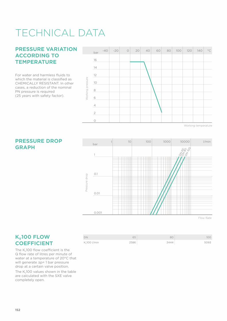
152
TECHNICAL DATA
-40 -20 0 20 40 60 80 100 120 140 °C
16
14
12
10
8
6
4
2
0
Wo
rkin
g p
ress
ure
Working temperature
barPRESSURE VARIATION ACCORDING TO TEMPERATURE
For water and harmless fluids to which the material is classified as CHEMICALLY RESISTANT. In other cases, a reduction of the nominal PN pressure is required (25 years with safety factor).
PRESSURE DROP GRAPH
Pre
ssu
re d
rop
Flow Rate
bar1 10 100 1000 10000 l/min
1
0.1
0.01
0.001
DN
65
DN
80
DN
100
KV100 FLOW COEFFICIENTThe Kv100 flow coefficient is the Q flow rate of litres per minute of water at a temperature of 20°C that will generate ∆p= 1 bar pressure drop at a certain valve position.The Kv100 values shown in the table are calculated with the SXE valve completely open.
DN 65 80 100
Kv100 l/min 2586 3444 5093

153
The information in this leaflet is provided in good faith. No liability will be accepted concerning technical data that is not directly covered by recognised international standards. FIP reserves the right to carry out any modification. Products must be installed and maintained by qualified personnel.
MINIMUM VALVE SEALING PRESSURE
The PVC-U SXE valve can only be used with liquids with specific weight under 1,37g/cm3.
DN 65 80 100
SXE (bar) 0.2 0.2 0.2
SSE (bar) 0.08 0.08 0.08

154
DIMENSIONS
d DN PN E H L Z g EPDM Code FPM Code
75 65 16 157 211 44 123 2605 SXEIV075E SXEIV075F
90 80 16 174 248 51 146 3300 SXEIV090E SXEIV090F
110 100 16 212 283 61 161 5770 SXEIV110E SXEIV110F
SXEIVEasyfit ball check valve with female ends for solvent welding, metric series
R DN PN E H L Z g EPDM Code FPM Code
2” 1/2 65 16 157 211 30.2 150.6 2605 SXEFV212E SXEFV212F
3” 80 16 174 248 33.3 181.4 3300 SXEFV300E SXEFV300F
4” 100 16 212 283 39.3 204.4 5770 SXEFV400E SXEFV400F
SXEFVEasyfit ball check valve with BSP threaded female ends
d DN PN E H L Z g EPDM Code FPM Code
2” 1/2 65 16 157 211 44 123 2605 SXELV212E SXELV212F
3” 80 16 174 248 51 146 3300 SXELV300E SXELV300F
4” 100 16 212 283 63 157 5770 SXELV400E SXELV400F
SXELVEasyfit ball check valve with female ends for solvent welding, BS series

155
d DN PN E H L Z g EPDM Code FPM Code
2” 1/2 65 16 157 211 44.5 122 2605 SXEAV212E SXEAV212F
3” 80 16 174 248 48 152 3300 SXEAV300E SXEAV300F
4” 100 16 212 283 57.5 168 5770 SXEAV400E SXEAV400F
SXEAVEasyfit ball check valve with female ends for solvent welding, ASTM series
R DN PN E H L Z g EPDM Code FPM Code
2” 1/2 65 16 157 211 33.2 144.6 2605 SXENV212E SXENV212F
3” 80 16 174 248 35.5 177 3300 SXENV300E SXENV300F
4” 100 16 212 283 37.6 207.8 5770 SXENV400E SXENV400F
SXENVEasyfit ball check valve with female ends, NPT thread
d DN PN E H L Z g EPDM Code FPM Code
2” 1/2 65 16 157 243 61 121 2605 SXEJV212E SXEJV212F
3” 80 16 174 272 64.5 143 3300 SXEJV300E SXEJV300F
4” 100 16 212 332 84 164 5770 SXEJV400E SXEJV400F
SXEJVEasyfit ball check valve with female ends for solvent welding, JIS series

156
R DN PN E H L Z g EPDM Code FPM Code
2” 1/2 65 16 157 211 35 141 2605 SXEGV212E SXEGV212F
3” 80 16 174 248 40 168 3300 SXEGV300E SXEGV300F
4” 100 16 212 283 45 193 5770 SXEGV400E SXEGV400F
SXEGVEasyfit ball check valve with female ends, JIS thread
d DN E H L Z g EPDM Code FPM Code
75 65 157 331 71 189 2605 SXEBEV075E SXEBEV075F
90 80 174 367 88 191 3300 SXEBEV090E SXEBEV090F
110 100 212 407 92 223 5770 SXEBEV110E SXEBEV110F
SXEBEVEasyfit ball check valve with PE100 SDR 11 male end connectors for butt welding or electrofusion (CVDE)

157
d DN PN E H L Z g EPDM Code FPM Code
75 65 16 157 211 44 123 2480 SSEIV075E SSEIV075F
90 80 16 174 248 51 146 3090 SSEIV090E SSEIV090F
110 100 16 212 283 61 161 5370 SSEIV110E SSEIV110F
SSEIVEasyfit spring check valve with female ends for solvent welding, metric series
R DN PN E H L Z g EPDM Code FPM Code
2” 1/2 65 16 157 211 30.2 150.6 2480 SSEFV212E SSEFV212F
3” 80 16 174 248 33.3 181.4 3090 SSEFV300E SSEFV300F
4” 100 16 212 283 39.3 204.4 5370 SSEFV400E SSEFV400F
SSEFVEasyfit spring check valve with BSP threaded female ends
d DN PN E H L Z g EPDM Code FPM Code
2” 1/2 65 16 157 211 44 123 2480 SSELV212E SSELV212F
3” 80 16 174 248 51 146 3090 SSELV300E SSELV300F
4” 100 16 212 283 63 157 5370 SSELV400E SSELV400F
SSELVEasyfit spring check valve with female ends for solvent welding, BS series

158
R DN PN E H L Z g EPDM Code FPM Code
2” 1/2 65 16 157 211 33.2 144.6 2480 SSENV212E SSENV212F
3” 80 16 174 248 35.5 177 3090 SSENV300E SSENV300F
4” 100 16 212 283 37.6 207.8 5370 SSENV400E SSENV400F
SSENVEasyfit spring check valve with female ends, NPT thread
d DN PN E H L Z g EPDM Code FPM Code
2” 1/2 65 16 157 243 61 121 2480 SSEJV212E SSEJV212F
3” 80 16 174 272 64.5 143 3090 SSEJV300E SSEJV300F
4” 100 16 212 332 84 164 5370 SSEJV400E SSEJV400F
SSEJVEasyfit spring check valve with female ends for solvent welding, JIS series
d DN PN E H L Z g EPDM Code FPM Code
2” 1/2 65 16 157 211 44.5 122 2480 SSEAV212E SSEAV212F
3” 80 16 174 248 48 152 3090 SSEAV300E SSEAV300F
4” 100 16 212 283 57.5 168 5370 SSEAV400E SSEAV400F
SSEAVEasyfit spring check valve with female ends for solvent welding, ASTM series

159
d DN E H L Z g EPDM Code FPM Code
75 65 157 331 71 189 2480 SSEBEV075E SSEBEV075F
90 80 174 367 88 191 3090 SSEBEV090E SSEBEV090F
110 100 212 407 92 223 5370 SSEBEV110E SSEBEV110F
SSEBEVEasyfit spring check valve with PE100 SDR 11 male end connectors for butt welding or electrofusion (CVDE)
R DN PN E H L Z g EPDM Code FPM Code
2” 1/2 65 16 157 211 35 141 2480 SSEGV212E SSEGV212F
3” 80 16 174 248 40 168 3090 SSEGV300E SSEGV300F
4” 100 16 212 283 45 193 5370 SSEGV400E SSEGV400F
SSEGVEasyfit spring check valve with female ends, JIS thread
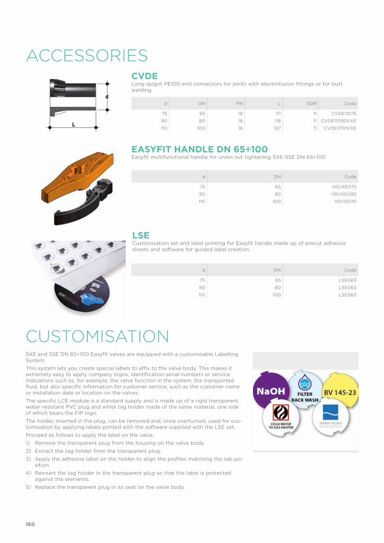
LSECustomisation set and label printing for Easyfit handle made up of precut adhesive sheets and software for guided label creation.
d DN Code
75 65 LSE063
90 80 LSE063
110 100 LSE063
d DN PN L SDR Code
75 65 16 111 11 CVDE11075
90 80 16 118 11 CVDE11090VXE
110 100 16 127 11 CVDE11110VXE
CVDELong spigot PE100 end connectors for joints with electrofusion fittings or for butt welding
d DN Code
75 65 HSVXE075
90 80 HSVXE090
110 100 HSVXE110
EASYFIT HANDLE DN 65÷100Easyfit multifunctional handle for union nut tightening SXE-SSE DN 65÷100
CUSTOMISATIONSXE and SSE DN 65÷100 Easyfit valves are equipped with a customisable Labelling System. This system lets you create special labels to affix to the valve body. This makes it extremely easy to apply company logos, identification serial numbers or service indications such as, for example, the valve function in the system, the transported fluid, but also specific information for customer service, such as the customer name or installation date or location on the valves.The specific LCE module is a standard supply and is made up of a rigid transparent water-resistant PVC plug and white tag holder made of the same material, one side of which bears the FIP logo. The holder, inserted in the plug, can be removed and, once overturned, used for cus-tomisation by applying labels printed with the software supplied with the LSE set.Proceed as follows to apply the label on the valve:1) Remove the transparent plug from the housing on the valve body.2) Extract the tag holder from the transparent plug.3) Apply the adhesive label on the holder to align the profiles matching the tab po-
sition.4) Reinsert the tag holder in the transparent plug so that the label is protected
against the elements.5) Replace the transparent plug in its seat on the valve body.
160
ACCESSORIES

COMPONENTSEXPLODED VIEW
1 Union nut (PVC-U - 2)2 End connector (PVC-U - 2)3 Socket seal O-Ring
(EPDM, FPM - 2)4 Body (PVC-U - 1) 5 Tag holder (PVC - 1)
* Also available made of A316 PTFE encapsulated
The component material and quantity supplied are indicated in the parentheses.
6 Transparent protection plug (PVC - 1)7 SXE Ball (PVC-U - 1)7 SSE Shutter (PVC-U - 1)8 Gland packing ring (PVC-U - 1)9 SXE Ball seat O-Ring
(EPDM, FPM - 1)
9 SSE Shutter seat O-ring (EPDM, FPM - 1)10 SXE Ball seat carrier
(PVC-U - 1)10 SSE Shutter seat carrier 11 Radial seal O-Ring
(EPDM, FPM - 1)12 Spring (STAINLESS steel* - 1)
SSESXE
161

DISMOUNTING ASSEMBLYSXESXE valves do not require maintenance in normal operating conditions. In the event of leaks or wear, before perform-ing maintenance, cut-off fluid upstream from the valve and make sure it is de-pressurised (downstream drain if neces-sary).1) Fully drain residual liquid that could
be aggressive for the operator and, if possible, circulate water to internally clean the valve.
2) For easy union nut tightening in as-sembly, use the Easyfit multifunction-al handle (supplied as an accessory).
3) Unscrew the ball seat carrier (10) with the Easyfit multifunctional han-dle: introduce the two protrusion on the top of the handle in the grooves in the carrier (10) and unscrew, ex-tracting it counter-clockwise.
4) Remove all internal components.
SSEIn the event of leaks or wear, before performing maintenance, cut-off fluid upstream from the valve and make sure it is de-pressurised (downstream drain if necessary).1) Fully drain residual liquid that could
be aggressive for the operator and, if possible, circulate water to internally clean the valve.
2) For easy union nut tightening in as-sembly, use the Easyfit multifunction-al handle (supplied as an accessory).
3) Unscrew the ball seat carrier (10) with the Easyfit multifunctional han-dle: introduce the two protrusion on the top of the handle in the grooves in the carrier (10) and unscrew, ex-tracting it counter-clockwise.
4) Remove all internal components.
SXE1) Reconstruct the valve following the
exploded view on the previous page.2) Tighten the ball seat carrier (10) us-
ing the Easyfit multifunctional handle. This ensures optimal valve installation and operations (fig. 3).
3) Position the valve between the end connectors (2) and tighten the union nuts clockwise (1) using the Easyfit multifunctional handle (fig. 7) being sure the socket seal O-ring (3) does not exit the seats.
SSE1) Reconstruct the valve following the
exploded view on the previous page.2) Tighten the ball seat carrier (10) us-
ing the Easyfit multifunctional handle. This ensures optimal valve installation and operations (fig. 3).
3) Position the valve between the end connectors (2) and tighten the union nuts clockwise (1) using the Easyfit multifunctional handle (fig. 7) being sure the socket seal O-ring (3) does not exit the seats.
Note: during assembly operations, it is advisable to lubricate the rubber seals. Mineral oils are not recommended for this task as they react aggressively with EPDM rubber.
Fig. 3
Fig. 4
Fig. 2
Fig. 1
162

INSTALLATIONFig. 5
Fig. 6
Fig. 7
Fig. 8
SXE and SSE valves can be installed both vertically (upward flow) and horizontally (SXE with minimum 0.2 bar back pressure).Before proceeding with installation. please follow these instructions carefully:1) Check that the pipes to be connected to the valve are aligned in order to avoid
mechanical stress on the threaded joints.2) Unscrew the union nuts (1) from the body (4) and insert them in the pipe seg-
ments.3) Solvent weld or screw the end connectors (2) onto the pipe segments.4) Position the valve body between the end connectors (fig. 1). 5) Place the union nuts on the valve body and start tightening manually clockwise
until they are hard to turn. Do not use wrenches or other tools that can damage the union nut surface (fig. 2).
6) For easy union nut tightening in assembly, use the Easyfit multifunctional handle (supplied as an accessory).
7) Extract the hooked insert in the handle (fig. 5) overturn it and fit it in the seat on the lower part of the handle (fig. 6).
8) Fit the tool on the external union nut profile until firmly and safely secured that allows for adequate torque without damaging the union nut in any way (fig. 7).
9) Repeat point 7 for the other union nut.10) When tightened, remove the hooked insert and replace it in its seat in the handle.11) If necessary, support the pipe with FIP pipe clip model ZIKM and DSM distance
plates.
WARNINGS- Do not use compressed air or other gases to test thermoplastic lines.- Always avoid sudden closing manoeuvres and protect the valve against accidental
manoeuvres.
163


FE DN 40÷200 PVC-U
Butterfly valve

166
Technical specificationsConstruction Bi-directional centric butterfly valveSize range DN 40 ÷ 200Nominal pressure Wafer version
DN 40÷50: PN 16 with water at 20 °CDN 65÷200: PN 10 with water at 20 °C Lug version DN 40÷125: PN 6 with water at 20 °CDN 150÷200: PN 4 with water at 20 °C
Temperature range 0 °C ÷ 60 °CCoupling standards Flanging system: EN ISO 1452, EN ISO 15493, DIN
2501, ISO 7005-1, EN 1092-1, ASTM B16.5 Cl.150
Reference standards Construction criteria: EN ISO 16136, EN ISO 1452, EN ISO 15493Test methods and requirements: ISO 9393Actuator couplings: ISO 5211
Valve material Body: PVC-U Disk: PVC-UStem: Zinc plated carbon steel (C45). On request STAINLESS steel AISI 316
Seal material Liner: EPDM, FPM. On request NBRControl options Hand lever operated; Gearbox, pneumatic actuator,
electric actuator
FE
The FE is a butterfly valve for shutting off or regulating flow, specifically designed for water applications and equipped with a customisable Labelling System.
BUTTERFLY VALVE
• Disk in PVC-U with through shaft • Zinc plated square section steel stem completely isolated from the fluid
complying with standard ISO 5211: DN 40 ÷ 65: 11 mm DN 80 ÷ 100: 14 mm DN 125 ÷ 150: 17 mm DN 200: 22 mm• Can also be installed as an end line valve, bottom discharge valve or tank
dump valve • The wafer valve can be transformed into a one-way Lug body valve
thanks to the set of zinc plated steel inserts available as an optional extra • Valve material compatibility (PVC-U) with water conveyance, drinking
water and other food substances according to current regulations • Possibility of directly installing a gearbox or pneumatic and/or electric
actuators with a standard drilling pattern according to standard ISO 5211 F05, F07, F10
DN 40÷200

167
1 Ergonomic multifunctional handle in HIPVC with the option for quick operation, graduated adjustment in 12 positions (every 7.5°). 180° reversible mounting
2 Customisable Labelling System: integrated module, made of a transparent protection plug customisable tag holder using the LSE set (available as
accessory). The customisation lets you identify the valve on the system according to the specific needs
3 Drilling pattern with oval slots that allow coupling to flanges according to numerous international standards
4 Interchangeable liner with the dual function of forming a hydraulic seal and isolating the body from the fluid.
5 One-piece top flange with PVC-U rack. Drilling according to standard ISO 5211 for direct drive:
DN 40 ÷ 65: F05 DN 80 ÷ 150: F07 DN 200: F10
2
3
4
5
1

168
DN 40 50 65 80 100 125 150 200
Kv100 l/min 1000 1285 1700 3550 5900 9850 18700 30500
bar10 100 1000 10000 100000 l/min
1
0,1
0,01
0,001
DN
40
DN
50
DN
65
DN
80
DN
100
DN
125
DN
150
DN
200
-40 -20 0 20 40 60 80 100 120 140 °C
16
14
12
10
8
6
4
2
0
bar
DN 40÷50
DN 65÷200
TECHNICAL DATA
KV100 FLOW COEFFICIENTThe Kv100 flow coefficient is the Q flow rate of litres per minute of water at a temperature of 20°C that will generate ∆p= 1 bar pressure drop at a certain valve position.The Kv100 values shown in the table are calculated with the valve completely open.
PRESSURE DROP GRAPH
Flow Rate
Wo
rkin
g p
ress
ure
Working temperature
PRESSURE VARIATION ACCORDING TO TEMPERATURE
For water and non-hazardous fluids with regard to which the material is classified as CHEMICALLY RESISTANT. In other cases, a reduction of the nominal pressure PN is required (25 years with safety factor).
Pre
ssu
re d
rop

169
RELATIVE FLOW COEFFICIENT GRAPH
The information in this leaflet is provided in good faith. No liability will be accepted concerning technical data that is not directly covered by recognised international standards. FIP reserves the right to carry out any modification. Products must be installed and maintained by qualified personnel.
OPERATING TORQUE AT MAXIMUM WORKING PRESSURE
40 50 65 80 100 125 150 200 DN
150
125
100
75
50
25
0
Op
erat
ing
to
rqu
e
Nm
5 10 15 20 25 30 35 40 45 50 55 60 65 70 75 80 85 90 100 %
100
90
80
70
60
50
40
30
20
10
0
Rel
ativ
e fl
ow
co
effici
ent
Percentage opening of the disk
%

170
d DN PN A min
A max B2 B3 C C1 C2 f H U Z g EPDM Code FPM Code
50 40 16 93.5 109 60 136 175 45 42 19 132 4 33 827 FEOVLM050E FEOVLM050F
63 50 16 108 124 70 143 175 45 42 19 147 4 43 1012 FEOVLM063E FEOVLM063F
75 65 10 128 144 80 168 175 45 45 19 165 4 46 1420 FEOVLM075E FEOVLM075F
90 80 10 145 159 90 182 250 45 45 19 130 4 49 1640 FEOVLM090E FEOVLM090F
110 100 10 165 190 105 196 250 45 45 19 150 4 56 1990 FEOVLM110E FEOVLM110F
*125 125 10 204 215 121 215 335 45 45 23 185 4 64 3030 FEOVLM140E FEOVLM140F
140 125 10 204 215 121 215 335 45 45 23 185 4 64 3030 FEOVLM140E FEOVLM140F
160 150 10 230 242 132 229 335 45 45 23 210 4 70 3730 FEOVLM160E FEOVLM160F
**200 200 10 280 298 161 309 425 65 82 23 325 8 71 8240 FEOVLM225E FEOVLM225F
225 200 10 280 298 161 309 425 65 82 23 325 8 71 8240 FEOVLM225E FEOVLM225F
d DN PN B2 B5 B6 G G1 G2 G3 U g EPDM Code FPM Code
75 65 10 80 173 145 48 135 39 125 4 2380 FEOVRM075E FEOVRM075F
90 80 10 90 187 159 48 135 39 125 4 2600 FEOVRM090E FEOVRM090F
110 100 10 105 201 173 48 135 39 125 4 2950 FEOVRM110E FEOVRM110F
*125 125 10 121 220 192 48 144 39 200 4 4400 FEOVRM140E FEOVRM140F
140 125 10 121 220 192 48 144 39 200 4 4400 FEOVRM140E FEOVRM140F
160 150 10 132 235 207 48 144 39 200 4 5100 FEOVRM160E FEOVRM160F
**200 200 10 161 288 257 65 175 60 200 8 9260 FEOVRM225E FEOVRM225F
225 200 10 161 288 257 65 175 60 200 8 9260 FEOVRM225E FEOVRM225F
FEOV/LMHand operated Butterfly valve
FEOV/RMGearbox operated Butterfly valve
DIMENSIONS
* FEOV D140 with special adaptor stubs D125
* FEOV D140 with special adaptor stubs D125

171
(1) installation with double flange(2) installation with single flange
LSE
FE LUG INSERT
ACCESSORIES
Customisation and label printing set for Easyfit handle made up of precut adhesive sheets and software for guided label creation
Size range: DN 40 ÷ 200 mm. Standard: ISO-DIN. PN: 6-4 bar with water at 20° C (used as end line). Threaded inserts are available to transform all the PVC-U butterfly valves of the FEOV series into Lug body valves.The zinc plated steel inserts can be easily fitted before installing the valve in the system and allow the valve itself to be used as a single flange end line valve in total safety.Lug butterfly valves are the unidirectional type when used as end line valves with a sin-gle flange, or as a connecting element for maintenance operations without needing to drain the lines
DN Code
40 LSE040
50 LSE040
65 LSE040
80 LSE040
100 LSE040
125 LSE040
150 LSE040
200 LSE040
DN PN (1) PN Lug (2) Code
40 12 6 KITLUG075ISO
50 1285 6 KITLUG075ISO
65 1700 6 KITLUG075ISO
80 3550 6 KITLUG090ISO
100 5900 6 KITLUG110ISO
125 9850 6 KITLUG140ISO
150 18700 4 KITLUG160ISO
200 30500 4 KITLUG225ISO

CUSTOMISATIONThe FE valve is equipped with the customisable Labelling System.This system lets you create special labels to insert in the handle. This makes it extremely easy to apply company logos, identification serial numbers or service information such as, for example, the valve function in the system, the transported fluid, but also specific information for customer service, such as the customer name or installation date or location on the valves.The specific LCE module is a standard supply and is made up of a rigid transparent water-resistant PVC plug (A-C) and white tag holder (B) made of the same material, one side of which bears the FIP logo (fig. 1).The tag holder, inserted in the plug, can be removed and, once overturned,used for customisation by applying labels printed with the software suppliedwith the LSE set.Proceed as follows to apply the label on the valve:1) Remove the upper part of the transparent plug (A) rotating it counter-clockwise
as indicated by the word "Open" on the plug and remove it.2) Extract the tag holder from its housing on the lower part of the plug (C)3) Apply the adhesive label on the holder (B) to align the profiles matching the tab
position.4) Reinsert the tag holder in its housing at the bottom of the plug 5) Reposition the top of the plug in the housing rotating it clockwise; this way the
label is protected against the elements.
Fig. 1
Fig. 2
ACTUATOR MOUNTING FLANGEThe valve can be equipped with standard pneumatic or electric actuators and gearbox for heavy-duty operations, using a flange in PP-GR reproducing the drilling pattern pro-vided for by standard ISO 5211.
DN J P Ø T Q
40 7 50 F 05 12 11
50 7 50 F 05 12 11
65 7 50 F 05 12 11
80 9 70 F 07 16 14
100 9 70 F 07 16 14
125 9 70 F 07 19 17
150 9 70 F 07 19 17
200 11 102 F 10 24 22
A
B
C
172

COMPONENTSEXPLODED VIEW DN 40÷50
1 Handle (HIPVC - 1)2 Screw (STAINLESS steel - 1)3 Washer (STAINLESS steel - 1)4 Transparent protection plug (PVC - 1)5 Stem (Zinc plated steel - 1)6 Stem O-Ring (EPDM or FPM - 1)7 Stem O-Ring (EPDM or FPM - 1)8 Seeger ring (STAINLESS steel - 1)9 Bush O-Ring (EPDM or FPM - 2)
10 Bush (Nylon - 1)11 Body (PVC-U - 1)12 Disk O-Ring (EPDM or FPM - 2)13 Anti-friction ring (PTFE - 2)14 Disk (PVC-U - 1)15 Liner (EPDM or FPM - 1)16 Washer (Steel- 1)17 Screw (STAINLESS steel - 1)18 Protection plug (PE - 1)
19 Screw (STAINLESS steel - 2)20 Plate (PVC-U - 1)21 Washer (STAINLESS steel - 2)22 Nut (STAINLESS steel - 2)23 Tag holder (PVC-U - 1)24 O-Ring (NBR - 2)25 Position indicator (PVC-U- 1)
The material of the component and the quantity supplied are indicated between brackets
173

EXPLODED VIEW DN 65÷200
1 Handle (HIPVC - 1)2 Screw (STAINLESS steel - 1)3 Washer (STAINLESS steel - 1)4 Transparent protection plug (PVC - 1)5 Stem (Zinc plated steel - 1)6 Stem O-Ring (EPDM or FPM - 1)7 Stem O-Ring (EPDM or FPM - 1)8 Seeger ring (STAINLESS steel - 1)9 Bush O-Ring (EPDM or FPM - 2)
10 Bush (Nylon - 1)11 Body (PVC-U - 1)12 Disk O-Ring (EPDM or FPM - 2)13 Anti-friction ring (PTFE - 2)14 Disk (PVC-U - 1)15 Liner (EPDM or FPM - 1)16 Washer (Steel- 1)17 Screw (STAINLESS steel - 1)18 Protection plug (PE - 1)
19 Screw (STAINLESS steel - 2)20 Plate (PVC-U - 1)21 Washer (STAINLESS steel - 2)22 Nut (STAINLESS steel - 2)23 Tag holder (PVC-U - 1)24 O-Ring (NBR - 2)25 Position indicator (PVC-U- 1)
The material of the component and the quantity supplied are indicated between brackets
174
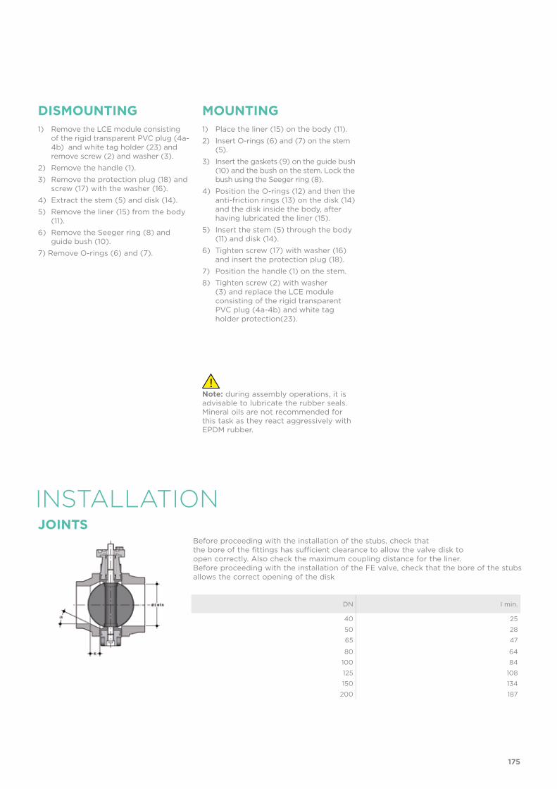
INSTALLATION
DISMOUNTING MOUNTING1) Remove the LCE module consisting
of the rigid transparent PVC plug (4a-4b) and white tag holder (23) and remove screw (2) and washer (3).
2) Remove the handle (1).
3) Remove the protection plug (18) and screw (17) with the washer (16).
4) Extract the stem (5) and disk (14).
5) Remove the liner (15) from the body (11).
6) Remove the Seeger ring (8) and guide bush (10).
7) Remove O-rings (6) and (7).
1) Place the liner (15) on the body (11).
2) Insert O-rings (6) and (7) on the stem (5).
3) Insert the gaskets (9) on the guide bush (10) and the bush on the stem. Lock the bush using the Seeger ring (8).
4) Position the O-rings (12) and then the anti-friction rings (13) on the disk (14) and the disk inside the body, after having lubricated the liner (15).
5) Insert the stem (5) through the body (11) and disk (14).
6) Tighten screw (17) with washer (16) and insert the protection plug (18).
7) Position the handle (1) on the stem.
8) Tighten screw (2) with washer (3) and replace the LCE module consisting of the rigid transparent PVC plug (4a-4b) and white tag holder protection(23).
Note: during assembly operations, it is advisable to lubricate the rubber seals. Mineral oils are not recommended for this task as they react aggressively with EPDM rubber.
JOINTSBefore proceeding with the installation of the stubs, check thatthe bore of the fittings has sufficient clearance to allow the valve disk toopen correctly. Also check the maximum coupling distance for the liner.Before proceeding with the installation of the FE valve, check that the bore of the stubs allows the correct opening of the disk
DN I min.
40 25
50 28
65 47
80 64
100 84
125 108
150 134
200 187
175

For the installation of PP-PE stubs, for butt welding a short spigot orelectrofusion/butt welding a long spigot, check the valve-stub couplings and the K - a chamfer dimensions where necessary according to the different SDR's in the following table.
Short/long spigot stubs according to EN ISO 15494 and DIN 16962/16963 and flange
dDN
5040
6350
7565
9080
110100
125100
140125
160150
180150
200200
225200
250250
280250
315300
50 40
63 50
75 65
90 80
110 100
140 125
160 150
225 200
17/17.6k=26.5a=20°
k=15.7a=25°
k=13.3a=25°
11k=35a=20°
k=35a=25°
k=40a=15°
k=32.5a=25°
k=35a=25°
k=34.5a=25°
7.4k=10a=35°
k=15a=35°
k=20a=30°
k=35a=20°
k=15a=35°
k=40a=20°
k=35a=30°
k=55a=30°
k=35a=30°
k=65a=30°
FK
val
veS
DR
Stub with female end for solvent welding according to EN ISO 1452 and DIN 8063- 4* With special stub d125 DN 125 for FE d140 DN 125 and flange d140 DN 125
** With special stub d200 DN 200 for FE d225 DN 200 and flange d225 DN 200
dDN
5040
6350
7565
9080
110100
125100
140125
160150
200200
225200
50 40
63 50
75 65
90 80
110 100
140 125 *160 150
225 200 **
FK
val
ve
To install on PVC-U stubs, check the valve-stub-flange couplings in the following table.
176
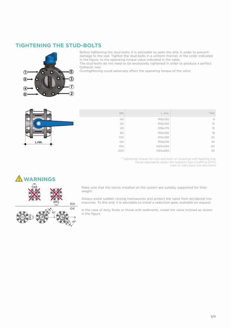
TIGHTENING THE STUD-BOLTSBefore tightening the stud-bolts, it is advisable to open the disk in order to prevent damage to the seal. Tighten the stud-bolts in a uniform manner, in the order indicated in the figure, to the operating torque value indicated in the table.The stud-bolts do not need to be excessively tightened in order to produce a perfect hydraulic seal.Overtightening could adversely affect the operating torque of the valve
WARNINGSMake sure that the valves installed on the system are suitably supported for their weight.
Always avoid sudden closing manoeuvres and protect the valve from accidental ma-noeuvres. To this end, it is advisable to install a reduction gear, available on request.
In the case of dirty fluids or those with sediments, install the valve inclined as shown in the figure.
NOOK
* Tightening torques for nuts and bolts on couplings with backing ring. Values required to obtain the hydraulic test (1.5xPN at 20°C)
(new or lubricated nuts and bolts)
DN L min. *Nm
40 M16x150 9
50 M16x150 12
65 M16x170 15
80 M16x180 18
100 M16x180 20
125 M16x210 35
150 M20x240 40
200 M20x260 55
177

FK DN 40÷400 PVC-U
Butterfly valve

180
Technical specificationsConstruction Bi-directional centric butterfly valveSize range DN 40÷400Nominal pressure Wafer version
DN 40÷50: PN 16 with water at 20° CDN 65÷250: PN 10 with water at 20° CDN 300: PN 8 with water at 20° CDN 350: PN 7 with water at 20° CDN 400: PN 6 with water at 20° CLug version DN 65÷200: PN 10 with water at 20° CDN 250÷300: PN 6 with water at 20° C
Temperature range 0 °C ÷ 60 °CCoupling standards Flanging system: EN ISO 1452, EN ISO 15493, DIN
2501, ISO 7005-1, EN 1092-1, ASTM B16.5 Cl.150
Reference standards Construction criteria: EN ISO 16136, EN ISO 1452, EN ISO 15493Test methods and requirements: ISO 9393Actuator couplings: ISO 5211
Valve material Body: PP-GRDisk: PVC-UStem: STAINLESS steel AISI 316
Seal material Liner: EPDM, FPM. On request NBRControl options Hand lever operated (DN 40÷200); Gearbox,
pneumatic actuator, electric actuator
FK
BUTTERFLY VALVE
• Interchangeable disk in PVC-U with through shaft, available in different thermoplastic materials: PP-H, PVC-C, ABS, PVDF
• Overall dimensions of the valve in accordance with standard ISO 5752 (DN 40÷200 Medium Series 25, DN 250÷ 300 Long Series 16) and DIN 3202 K2 and ISO 5752 (DN 65÷200 K2, DN 250÷300 K3)
• Can also be installed as an end line valve, bottom discharge valve or tank dump valve
• Special Lug version PN 10 fully drilled to DIN 2501 or ANSI B16.5 cl.150 with molded-in AISI 316 stainless steel threaded inserts
• Valve material compatibility (PVC-U + EPDM) with water conveyance, drinking water and other food substances according to current regula-tions
• Possibility of installing a manual reducer or pneumatic and/or electric actuators by applying an ISO standard drilling PP-GR flanges. DN 40 ÷ 200 valve fitted with plate with rack in PP-GR. For actuated versions with flange drilled according to ISO 5211 F05, F07, F10. DN 250÷400 valve, fitted with one-piece top flange in high mechanical strength PP-GR with mounting flange for internal components drilled according to standard ISO 5211 F10 (excluding DN 350÷400), F12, F14.
DN 40÷400

181
1 Ergonomic handle in HIPVC equipped with locking and unlocking device, release, quick operation and graduated adjustment in 10 intermediate positions (DN 40÷200). The operating range, starting from the first few degrees of valve opening, also guarantees extremely low pressure drops.
2 Customisable Labelling System: integrated module in the handle, made of a transparent protection plug and a customisable tag holder using the LSE set (available as an accessory). The customisation lets you identify the valve on the system according to specific needs.
3 STAINLESS steel square section stem completely isolated from the fluid complying with standard
ISO 5211: DN 40÷65: 11 mm DN 80÷100: 14 mm DN 125÷150: 17 mm DN 200: 22 mm DN 250÷400: 27 mm
4 Body in polypropylene based compound reinforced with fibreglass (PP-GR) resistant to UV rays and characterised by high mechanical strength.
5 Drilling pattern using oval slots that allow coupling to flanges according to numerous
international standards. The special self-centring inserts in ABS supplied for DN 40÷200 guarantee the correct axial alignment of the valve during installation.
For DN 250÷400 valves, the drilling pattern for the self-centring system is of the traditional type according to DIN and ANSI standards.
6 Interchangeable liner with the dual function of forming a hydraulic seal and isolating the body from the fluid.
2
3
1
4 5
6

182
TECHNICAL DATA
DN 40 50 65 80 100 125 150 200 250 300 350 400
Kv100 l/min 1000 1285 1700 3550 5900 9850 18700 30500 53200 81600 94100 124900
KV100 FLOW COEFFICIENTThe Kv100 flow coefficient is the Q flow of litres per minute of water at a temperature of 20°C that will generate ∆p= 1 bar pressure drop at a certain valve position.The Kv100 values shown in the table are calculated with the valve completely open.
PRESSURE DROP GRAPH
Pre
ssu
re d
rop
Flow rate
bar10 100 1000 10000 100000 l/min
1
0.1
0.01
0.001
DN
40
DN
50
DN
65
DN
80
DN
100
DN
125
DN
150
DN
20
0D
N 2
50D
N 3
00
DN
350
DN
40
0
-40 -20 0 20 40 60 80 100 120 140 °C
16
14
12
10
8
6
4
2
0
Wo
rkin
g p
ress
ure
Working temperature
barPRESSURE VARIATION ACCORDING TO TEMPERATURE
For water and harmless fluids to which the material is classified as CHEMICALLY RESISTANT. In other cases, a reduction of the nominal PN pressure is required (25 years with safety factor).
DN 40÷50
DN 65÷250
DN 300DN 350DN 400

183
DN 40 50 65 80 100 125 150 200 250 300 350 400
Kv100 l/min 1000 1285 1700 3550 5900 9850 18700 30500 53200 81600 94100 124900
The information in this leaflet is provided in good faith. No liability will be accepted concerning technical data that is not directly covered by recognised international standards. FIP reserves the right to carry out any modification. Products must be installed and maintained by qualified personnel.
OPERATING TORQUE AT MAXIMUM WORKING PRESSURE
40 50 65 80 100 125 150 200 250 300 350 400 DN
650
600
550
500
450
400
350
300
250
200
150
100
50
0
Op
erat
ing
to
rqu
e
Nm
RELATIVE FLOW COEFFICIENT GRAPH
5 10 15 20 25 30 35 40 45 50 55 60 65 70 75 80 85 90 100 %
100
90
80
70
60
50
40
30
20
10
0
Rel
ativ
e fl
ow
co
effici
ent
Percentage opening of the disk
%
The relative flow coefficient is the flow rate through the valve as a function of the degree of valve opening.

184
d DN PN A min A max B2 B3 C C1 H U Z g EPDM Code FPM Code
50 40 16 99 109 60 137 175 100 132 4 33 1000 FKOVLM050E FKOVLM050F
63 50 16 115 125.5 70 143 175 100 147 4 43 1180 FKOVLM063E FKOVLM063F
75 65 10 128 144 80 164 175 110 165 4 46 1570 FKOVLM075E FKOVLM075F
90 80 10 145 160 93 178 272 110 185 8 49 2020 FKOVLM090E FKOVLM090F
110 100 10 165 190 107 192 272 110 211 8 56 2370 FKOVLM110E FKOVLM110F
140 125 10 204 215 120 212 330 110 240 8 64 3300 FKOVLM140E FKOVLM140F
160 150 10 230 242 134 225 330 110 268 8 70 4100 FKOVLM160E FKOVLM160F
225 200 10 280 298 161 272 420 122 323 8 71 7050 FKOVLM225E FKOVLM225F
d DN PN øA B2 B3 C C1 f H U Z g EPDM Code FPM Code
75 65 10 145 80 164 175 110 M16 165 4 46 1870 FKOLVLM075E FKOLVLM075F
90 80 10 160 93 178 175 110 M16 185 8 49 2670 FKOLVLM090E FKOLVLM090F
110 100 10 180 107 192 272 110 M16 211 8 56 3020 FKOLVLM110E FKOLVLM110F
140 125 10 210 120 212 330 110 M16 240 8 64 4700 FKOLVLM140E FKOLVLM140F
160 150 10 240 134 225 330 110 M20 268 8 70 5450 FKOLVLM160E FKOLVLM160F
225 200 10 295 161 272 420 122 M20 323 8 71 8350 FKOLVLM225E FKOLVLM225F
d DN PN øA B2 B3 C C1 f H U Z g EPDM Code FPM Code
2” 1/2 65 10 139.7 80 164 175 110 5/8” 165 4 46 1870 FKOALVLM212E FKOALVLM212F
3” 80 10 152.4 93 178 175 110 5/8” 185 8 49 2670 FKOALVLM300E FKOALVLM300F
4” 100 10 190.5 107 192 272 110 5/8” 211 8 56 3020 FKOALVLM400E FKOALVLM400F
5” 125 10 215.9 120 212 330 110 3/4” 240 8 64 4700 FKOALVLM500E FKOALVLM500F
6” 150 10 241.3 134 225 330 110 3/4” 268 8 70 5450 FKOALVLM600E FKOALVLM600F
8” 200 10 298.4 161 272 420 122 3/4” 323 8 71 8350 FKOALVLM800E FKOALVLM800F
FKOV/LMHand operated Butterfly valve
FKOV/LM LUG ISO-DINHand operated Butterfly valve, version Lug ISO-DIN
FKOV/LM LUG ANSIHand operated Butterfly valve, version Lug ANSI
DIMENSIONS

185
d DN PN A min A max øA B1 B2 f H U Z g EPDM Code FPM Code
50 40 16 99 109 - 106 60 19 132 4 33 574 FKOVFM050E FKOVFM050F
63 50 16 115 125.5 - 112 70 19 147 4 43 754 FKOVFM063E FKOVFM063F
75 65 10 128 144 - 119 80 19 165 4 46 1000 FKOVFM075E FKOVFM075F
90 80 10 145 160 - 133 93 19 185 8 49 1400 FKOVFM090E FKOVFM090F
110 100 10 165 190 - 147 107 19 211 8 56 1750 FKOVFM110E FKOVFM110F
*125 125 10 204 215 - 167 120 23 240 8 64 2550 FKOVFM140E FKOVFM140F
140 125 10 204 215 - 167 120 23 240 8 64 2550 FKOVFM140E FKOVFM140F
160 150 10 230 242 - 180 134 23 268 8 70 3300 FKOVFM160E FKOVFM160F
**200 200 10 280 298 - 227 161 23 323 8 71 6000 FKOVFM225E FKOVFM225F
225 200 10 280 298 - 227 161 23 323 8 71 6000 FKOVFM225E FKOVFM225F
***250 250 10 - - 350 248 210 22 405 12 114 12000 FKOVFM280E FKOVFM280F
***280 250 10 - - 350 248 210 22 405 12 114 12000 FKOVFM280E FKOVFM280F
***315 300 8 - - 400 305 245 22 475 12 114 19000 FKOVFM315E FKOVFM315F
***355 350 7 - - 460 330 280 22 530 16 129 26000 FKOVFM355E FKOVFM355F
***400 400 6 - - 515 350 306 26 594 16 169 34000 FKOVFM400E FKOVFM400F
****10” 250 10 - - 362 248 210 25.4 405 12 114 12000 FKOAVFM810E FKOAVFM810F
****12” 300 8 - - 432 305 245 25.4 475 12 114 19000 FKOAVFM812E FKOAVFM812F
****14” 350 7 - - 476 330 280 28.5 530 12 129 26000 FKOAVFM814E FKOAVFM814F
****16” 400 6 - - 540 350 306 28.5 594 16 169 34000 FKOAVFM816E FKOAVFM816F
d DN PN øA B1 B2 f H U Z g EPDM Code FPM Code
75 65 10 145 119 80 M16 165 4 46 1400 FKOLVFM075E FKOLVFM075F
90 80 10 160 133 93 M16 185 8 49 2200 FKOLVFM090E FKOLVFM090F
110 100 10 180 147 107 M16 211 8 56 2550 FKOLVFM110E FKOLVFM110F
140 125 10 210 167 120 M16 240 8 64 4150 FKOLVFM140E FKOLVFM140F
160 150 10 240 180 134 M20 268 8 70 4900 FKOLVFM160E FKOLVFM160F
225 200 10 295 227 161 M20 323 8 71 7600 FKOLVFM225E FKOLVFM225F
FKOV/FM LUG ISO-DINBare shaft Butterfly valve, version Lug ISO-DIN
FKOV/FMButterfly valve with bare shaft
*FKOV d140 with special adapter collars d125 **FKOV d225 with special adapter collars d200
***ISO-DIN****ANSI B16.5 cl. 150

186
FKOV/RMGearbox operated Butterfly valve
d DN PN A min
A max øA B2 B5 B6 G G1 G2 G3 H U Z g EPDM Code FPM Code
50 40 16 99 109 - 60 161 133 48 135 39 125 132 4 33 1974 FKOVRM050E FKOVRM050F
63 50 16 115 125.2 - 70 167 139 48 135 39 125 147 4 43 2154 FKOVRM063E FKOVRM063F
75 65 10 128 144 - 80 174 146 48 135 39 125 165 4 46 2400 FKOVRM075E FKOVRM075F
90 80 10 145 160 - 93 188 160 48 135 39 125 185 8 49 2800 FKOVRM090E FKOVRM090F
110 100 10 165 190 - 107 202 174 48 135 39 125 211 8 56 3150 FKOVRM110E FKOVRM110F
*125 125 10 204 215 - 120 222 194 48 144 39 200 240 8 64 4450 FKOVRM140E FKOVRM140F
140 125 10 204 215 - 120 222 194 48 144 39 200 240 8 64 4450 FKOVRM140E FKOVRM140E
160 150 10 230 242 - 134 235 207 48 144 39 200 268 8 70 5200 FKOVRM160E FKOVRM160F
**200 200 10 280 298 - 161 287 256 65 204 60 200 323 8 71 9300 FKOVRM225E FKOVRM225F
225 200 10 280 298 - 161 287 256 65 204 60 200 323 8 71 9300 FKOVRM225E FKOVRM225F
***250 250 10 - - 350 210 317 281 88 236 76 250 405 12 114 18600 FKOVRM280E FKOVRM280F
***280 250 10 - - 350 210 317 281 88 236 76 250 405 12 114 18600 FKOVRM280E FKOVRM280F
***315 300 8 - - 400 245 374 338 88 236 76 250 475 12 114 25600 FKOVRM315E FKOVRM315F
***355 350 7 - - 460 280 438 390 88 361 80 300 530 16 129 34450 FKOVRM355E FKOVRM355F
***400 400 6 - - 515 306 438 390 88 361 80 300 594 16 169 42450 FKOVRM400E FKOVRM400F
****10” 250 10 - - 362 210 317 281 88 236 76 250 405 12 114 18600 FKOAVRM810E FKOAVRM810F
****12” 300 8 - - 432 245 374 338 88 236 76 250 475 12 114 25600 FKOAVRM812E FKOAVRM812F
****14” 350 7 - - 476 280 438 390 88 361 80 300 530 12 129 34450 FKOAVRM814E FKOAVRM814F
****16” 400 6 - - 540 306 438 390 88 361 80 300 594 16 169 42450 FKOAVRM816E FKOAVRM816F
*FKOV d140 with special adapter collars d125**FKOV d225 with special adapter collars d200
***ISO-DIN****ANSI B16.5 cl. 150
d DN PN øA B1 B2 f H U Z g EPDM Code FPM Code
2” 1/2 65 10 145 119 80 5/8” 165 4 46 1400 FKOALVFM212E FKOALVFM212F
3” 80 10 160 133 93 5/8” 185 8 49 2200 FKOALVFM300E FKOALVFM300F
4” 100 10 180 147 107 5/8” 211 8 56 2550 FKOALVFM400E FKOALVFM400F
5” 125 10 210 167 120 3/4” 240 8 64 4150 FKOALVFM500E FKOALVFM500F
6” 150 10 240 180 134 3/4” 268 8 70 4900 FKOALVFM600E FKOALVFM600F
8” 200 10 295 227 161 3/4” 323 8 71 7600 FKOALVFM800E FKOALVFM800F
10” 250 6 362 248 210 7/8” 405 12 114 16800 FKOALVFM810E FKOALVFM810F
12” 300 6 431.8 305 245 7/8” 475 12 114 23800 FKOALVFM812E FKOALVFM812F
FKOV/FM LUG ANSIBare shaft Butterfly valve, version Lug ANSI

187
FKOV/RM LUG ANSIGearbox operated Butterfly valve, version Lug ANSI
FKOV/RM LUG ISO-DINGearbox operated Butterfly valve, version Lug ISO-DIN
d DN PN øA B2 B5 B6 f G G1 G2 G3 H U Z g EPDM Code FPM Code
75 65 10 145 80 174 146 M16 48 135 39 125 165 4 46 2800 FKOLVRM075E FKOLVRM075F
90 80 10 160 93 188 160 M16 48 135 39 125 185 8 49 3600 FKOLVRM090E FKOLVRM090F
110 100 10 180 107 202 174 M16 48 135 39 125 211 8 56 3950 FKOLVRM110E FKOLVRM110F
140 125 10 210 120 222 194 M16 48 144 39 200 240 8 64 6050 FKOLVRM140E FKOLVRM140F
160 150 10 240 134 235 207 M20 48 144 39 200 268 8 70 6800 FKOLVRM160E FKOLVRM160F
225 200 10 295 161 287 256 M20 65 204 60 200 323 8 71 10900 FKOLVRM225E FKOLVRM225F
d DN PN øA B2 B5 B6 f G G1 G2 G3 H U Z g EPDM Code Code
2” 1/2 65 10 139.7 80 174 146 5/8” 48 135 39 125 165 4 46 2800 FKOALVRM212E FKOALVRM212F
3” 80 10 152.4 93 188 160 5/8” 48 135 39 125 185 8 49 3600 FKOALVRM300E FKOALVRM300F
4” 100 10 190.5 107 202 174 5/8” 48 135 39 125 211 8 56 3950 FKOALVRM400E FKOALVRM400F
5” 125 10 215.9 120 222 194 3/4” 48 144 39 200 240 8 64 6050 FKOALVRM500E FKOALVRM500F
6” 150 10 241.3 134 235 207 3/4” 48 144 39 200 268 8 70 6800 FKOALVRM600E FKOALVRM600F
8” 200 10 298.4 161 287 256 3/4” 65 204 60 200 323 8 71 10900 FKOALVRM800E FKOALVRM800F
10” 250 6 362 210 317 281 7/8” 88 236 76 250 405 12 114 23400 FKOALVRM810E FKOALVRM810F
12” 300 6 431.8 245 374 338 7/8” 88 236 76 250 475 12 114 30400 FKOALVRM812E FKOALVRM812F

188
FK MS
LSE
ACCESSORIESThe MS kit lets you install a limit switch with electromechanical or inductive micro switches on a manual FK/LM valve to remotely signal the valve position (open-closed). The kit can be assembled on the valve even if already installed on the system.
Customisation set and label printing for Easyfit handle made up of precut adhesive sheets and software for guided label creation.
DN B2 B3 C1Protection
rateElectromechanical
codeInductive
codeNamur
code
40 60 248 80 IP67 FKMS0M FKMS0I FKMS0N
50 70 254 80 IP67 FKMS0M FKMS0I FKMS0N
65 80 261 80 IP67 FKMS0M FKMS0I FKMS0N
80 93 275 80 IP67 FKMS1M FKMS1I FKMS1N
100 107 289 80 IP67 FKMS1M FKMS1I FKMS1N
125 120 309 80 IP67 FKMS1M FKMS1I FKMS1N
150 134 322 80 IP67 FKMS1M FKMS1I FKMS1N
200 161 369 80 IP67 FKMS2M FKMS2I FKMS2N
DN Code
40 LSE040
50 LSE040
65 LSE040
80 LSE040
100 LSE040
125 LSE040
150 LSE040
200 LSE040
Electromechanical Inductive Namur

189
Actuator mounting flangeThe valve can be equipped with standard pneumatic or electric actuators and gearbox for heavy-duty operations, using a flange in PP-GR reproducing the drilling pattern pro-vided for by standard ISO 5211.
DN J P Ø T Q
40 7 50 F 05 12 11
50 7 50 F 05 12 11
65 7/9 50/70 F 05/F 07 12 11
80 9 70 F 07 16 14
100 9 70 F 07 16 14
125 9 70 F 07 19 17
150 9 70 F 07 19 17
200 11 102 F 10 24 22
200 11 102 F 10 24 22
250 11/13/17 102/125/140 F 10/F 12/F 14 29 27
300 11/13/17 102/125/140 F 10/F 12/F 14 29 27
350 14/18 125/140 F 12/F 14 29 27
400 14/18 125/140 F 12/F 14 29 27
CUSTOMISATIONThe FK valve is equipped with the customisable Labelling System.This system lets you create special labels to insert in the handle. This makes it extremely easy to apply company logos, identification serial numbers or service indications such as, for example, the valve function in the system, the transported fluid, but also specific information for customer service, such as the customer name or installation date or location on the valves.The specific LCE module is a standard supply and is made up of a rigid transparent water-resistant PVC plug (A-C) and white tag holder (B) made of the same material, one side of which bears the FIP logo (fig. 1).The tag holder, inserted in the plug, can be removed and, once overturned, used for customisation by applying labels printed with the software supplied with the LSE set. Proceed as follows to apply the label on the valve:1) Remove the upper part of the transparent plug (A) rotating it counter-clockwise
as indicated by the word "Open" on the plug and remove it.2) Extract the tag holder from its housing on the lower part of the plug (C).3) Apply the adhesive label on the holder (B) to align the profiles matching the tab
position.4) Reinsert the tag holder in its housing at the bottom of the plug. 5) Reposition the top of the plug in the housing rotating it clockwise; this way the
label is protected against the elements.
Fig. 1
Fig. 2
A
B
C

COMPONENTSEXPLODED VIEW DN 40÷50
The component material and quantity supplied are indicated in the parentheses.
1 Position indicator (PA - 1)2 Handle (HIPVC - 1)3a/b Transparent protection plug (PVC - 1)4 Fastening screw (STAINLESS steel - 1)5 Washer (STAINLESS Steel - 1)6 Flange (PP-GR - 1)7 Screw (STAINLESS Steel - 2)8 Tag holder (PVC-U - 1)9 O-Ring (NBR - 1)
10 Plate (PP-GR - 1)11 Washer (STAINLESS Steel - 2)12 Nut (STAINLESS Steel - 2)13 Seeger ring (STAINLESS steel - 1)14 Stem (STAINLESS steel 316 - 1)15 Bush O-Ring (FPM - 2)16 Bush (Nylon - 1)17 Stem O-Ring (FPM - 1)18 Stem O-Ring (FPM - 1)19 Body (PP-GR - 1)
20 Protection plug (PE - 1)21 Screw ((STAINLESS steel - 1)22 Washer (STAINLESS steel - 1)23 Anti-friction ring (PTFE - 2)24 Disk O-Ring (FPM - 2)25 Disk (PVC-U- 1)26 Liner (EPDM or FPM - 1)27 Inserts (ABS - 4-8)28 Plug (PE - 2)
190

EXPLODED VIEW DN 65÷200
1 Position indicator (PA - 1)2 Handle (HIPVC - 1)3a/b Transparent protection plug (PVC - 1)4 Fastening screw (STAINLESS steel - 1)5 Washer (STAINLESS Steel - 1)6 Flange (PP-GR - 1)7 Screw (STAINLESS Steel - 2)8 Tag holder (PVC-U - 1)
9 O-Ring (NBR - 1)10 Plate (PP-GR - 1)11 Washer (STAINLESS Steel - 2)12 Nut (STAINLESS Steel - 2)13 Seeger ring (STAINLESS Steel - 1)14 Stem (STAINLESS steel 316 - 1)15 Bush O-Ring (FPM - 2)16 Bush (Nylon - 1)17 Stem O-Ring (FPM - 1)18 Stem O-Ring (FPM - 1)
19 Body (PP-GR - 1)20 Protection plug (PE - 1)21 Screw ((STAINLESS steel - 1)22 Washer (STAINLESS steel - 1)23 Anti-friction ring (PTFE - 2)24 Disk O-Ring (FPM - 2)25 Disk (PVC-U - 1)26 Liner (EPDM o FPM - 1)27 Inserts (ABS - 4-8)28 Plug (PE - 2)
The component material and quantity supplied are indicated in the parentheses.
191

EXPLODED VIEW DN 250÷300
1 Body (PP-GR - 1)2 Washer (STAINLESS Steel - 1)3 Bush (PP - 1)4 Bush O-Ring (FPM - 4)5 Bush (PP - 2)6 Washer (PTFE - 2)7 Liner (EPDM o FPM - 1)
8 Anti-friction ring (PTFE - 2)9 Disk O-Ring (FPM - 2)10 Disk (PVC-U - 1)11 Washer (STAINLESS Steel - 2)12 Washer (STAINLESS Steel - 1)13 Protection plug (PE - 1)14 Screw ((STAINLESS steel - 1)15 Washer (STAINLESS Steel - 1)
16 Stem (STAINLESS steel 316 - 1)17 Stem O-Ring (FPM - 2)18 Seeger ring (STAINLESS steel - 1)19 O-Ring (FPM - 2)
The component material and quantity supplied are indicated in the parentheses.
192

EXPLODED VIEW DN 350÷400
1 Body (PP-GR - 1)2 Washer (STAINLESS Steel - 1)3 Bush (PP-H - 1)4 Bush O-Ring (EPDM or FPM - 6)5 Bush (PP-H - 1)6 Washer (PP-H - 2)7 Liner (EPDM or FPM - 1)8 Anti-friction ring (PTFE - 2)
9 Disk O-Ring (EPDM or FPM - 2)10 Disk (PVC-U - 1)11 Washer (STAINLESS Steel - 1)12 Washer (STAINLESS Steel - 1)13 Protection plug (PE - 1)14 Screw (Screw (STAINLESS steel - 1)16 Stem (STAINLESS steel 316 - 1)17 Stem O-Ring (EPDM or FPM - 2)
18 Seeger ring (STAINLESS steel - 1)20 Gearbox (Al, Steel - 1)21 Pin (STAINLESS steel - 2)22 Washer (STAINLESS steel - 1)23 Position indicator (PA - 1)
The component material and quantity supplied are indicated in the parentheses.
193
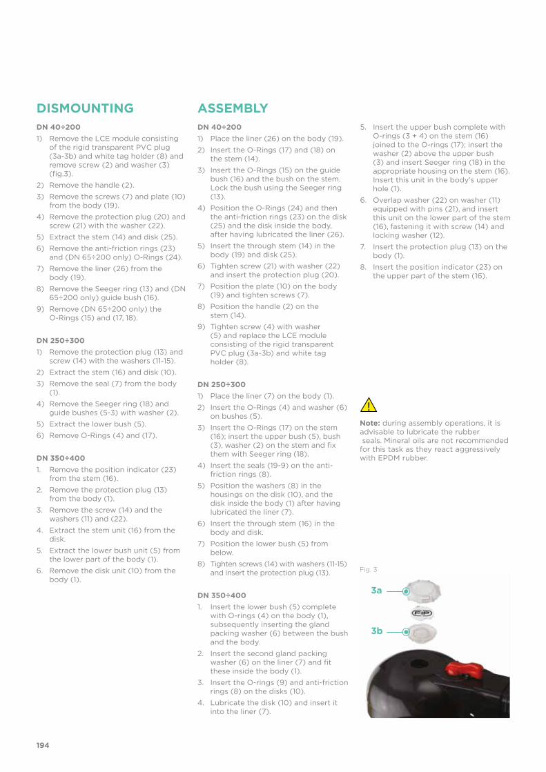
DISMOUNTING ASSEMBLYDN 40÷200 1) Place the liner (26) on the body (19).
2) Insert the O-Rings (17) and (18) on the stem (14).
3) Insert the O-Rings (15) on the guide bush (16) and the bush on the stem. Lock the bush using the Seeger ring (13).
4) Position the O-Rings (24) and then the anti-friction rings (23) on the disk (25) and the disk inside the body, after having lubricated the liner (26).
5) Insert the through stem (14) in the body (19) and disk (25).
6) Tighten screw (21) with washer (22) and insert the protection plug (20).
7) Position the plate (10) on the body (19) and tighten screws (7).
8) Position the handle (2) on the stem (14).
9) Tighten screw (4) with washer (5) and replace the LCE module consisting of the rigid transparent PVC plug (3a-3b) and white tag holder (8).
DN 250÷300 1) Place the liner (7) on the body (1).
2) Insert the O-Rings (4) and washer (6) on bushes (5).
3) Insert the O-Rings (17) on the stem (16); insert the upper bush (5), bush (3), washer (2) on the stem and fix them with Seeger ring (18).
4) Insert the seals (19-9) on the anti-friction rings (8).
5) Position the washers (8) in the housings on the disk (10), and the disk inside the body (1) after having lubricated the liner (7).
6) Insert the through stem (16) in the body and disk.
7) Position the lower bush (5) from below.
8) Tighten screws (14) with washers (11-15) and insert the protection plug (13).
DN 350÷4001. Insert the lower bush (5) complete
with O-rings (4) on the body (1), subsequently inserting the gland packing washer (6) between the bush and the body.
2. Insert the second gland packing washer (6) on the liner (7) and fit these inside the body (1).
3. Insert the O-rings (9) and anti-friction rings (8) on the disks (10).
4. Lubricate the disk (10) and insert it into the liner (7).
Note: during assembly operations, it is advisable to lubricate the rubber seals. Mineral oils are not recommendedfor this task as they react aggressively with EPDM rubber.
DN 40÷200 1) Remove the LCE module consisting
of the rigid transparent PVC plug (3a-3b) and white tag holder (8) and remove screw (2) and washer (3) (fig.3).
2) Remove the handle (2).
3) Remove the screws (7) and plate (10) from the body (19).
4) Remove the protection plug (20) and screw (21) with the washer (22).
5) Extract the stem (14) and disk (25).
6) Remove the anti-friction rings (23) and (DN 65÷200 only) O-Rings (24).
7) Remove the liner (26) from the body (19).
8) Remove the Seeger ring (13) and (DN 65÷200 only) guide bush (16).
9) Remove (DN 65÷200 only) the O-Rings (15) and (17, 18).
DN 250÷300 1) Remove the protection plug (13) and
screw (14) with the washers (11-15).
2) Extract the stem (16) and disk (10).
3) Remove the seal (7) from the body (1).
4) Remove the Seeger ring (18) and guide bushes (5-3) with washer (2).
5) Extract the lower bush (5).
6) Remove O-Rings (4) and (17).
DN 350÷400 1. Remove the position indicator (23)
from the stem (16).
2. Remove the protection plug (13) from the body (1).
3. Remove the screw (14) and the washers (11) and (22).
4. Extract the stem unit (16) from the disk.
5. Extract the lower bush unit (5) from the lower part of the body (1).
6. Remove the disk unit (10) from the body (1).
5. Insert the upper bush complete with O-rings (3 + 4) on the stem (16) joined to the O-rings (17); insert the washer (2) above the upper bush (3) and insert Seeger ring (18) in the appropriate housing on the stem (16). Insert this unit in the body's upper hole (1).
6. Overlap washer (22) on washer (11) equipped with pins (21), and insert this unit on the lower part of the stem (16), fastening it with screw (14) and locking washer (12).
7. Insert the protection plug (13) on the body (1).
8. Insert the position indicator (23) on the upper part of the stem (16).
194
Fig. 3
3a
3b

INSTALLATION
Before proceeding with the installation of the stubs, check that the bore of the fittings has sufficient clearance to allow the valve disk to open correctly. Also check the maximum coupling distance for the liner. Before proceeding with the installation of the FK valve, check that the bore of the stub allows the correct opening of the disk.
DN I min.
40 25
50 28
65 47
80 64
100 84
125 108
150 134
200 187
250 225
300 280
350 324
400 362
JOINTS
195
To install on PVC-U collars, check the valve-collar-flange couplings in the following table.
Stub with female end for solvent welding according to EN ISO 1452 and DIN 8063- 4* With special collar d125 DN125 for FK d140 DN125 and flange d140 DN125
** With special collar d200 DN200 for FK d225 DN200 and flange d225 DN200
dDN
5040
6350
7565
9080
110100
125100
140125
160150
180150
200200
225200
250250
280250
315300
355350
400400
50 40
63 50
75 65
90 80
110 100
140 125 *160 150
225 200 **280 250
315 300
355 350
400 400
FK
val
ve

POSITIONING THE INSERTSPOS. 1
POS. 2
Place the inserts in the holes according to the positions indicated in the table, from the side corresponding to the letters D and DN in order to facilitate the insertion of the stud-bolts and the coupling with the flanges (DN 40 ÷ 200). The self-centring inserts must be inserted in the guides in the slots in the valve body on the side with the writing, with the writing facing upwards, and positioned according to the type of flange drilling, as indicated in the following table:
DN DIN 2501 PN6, EN 1092-1,
BS 4504 PN6, DIN 8063 PN6
DIN 2501 PN10/16, EN 1092-1, BS 4504 PN 10/16, DIN 8063
PN 10/16, EN ISO 15493, EN ISO 1452
BS 10 table A-D-E
Spec D-E
BS 1560 cl.150,
ANSI B16.5 cl.150 *
JIS B 2220
K5
JIS 2211
K10**
DN 40 Pos. 1 Pos. 2 Pos. 1 Pos. 1 Pos. 1 -
DN 50 Pos. 1 Pos. 2 Pos. 1 - N/A -
DN 65 Pos. 1 Pos. 2 Pos. 1 Pos. 2 Pos. 1 Pos. 2
DN 80 Pos. 1 Pos. 2 Pos. 1 Pos. 2 Pos. 1 Pos. 1
DN 100 Pos. 1 Pos. 2 Pos. 1 Pos. 2 Pos. 1 Pos. 1
DN 125 Pos. 1 Pos. 2 Pos. 1 Pos. 2 Pos. 1 -
DN 150 Pos. 1 Pos. 2 Pos. 1 Pos. 2 Pos. 1 Pos. 2
DN 200 Pos. 1 PN 10 Pos. 2 Pos. 2 Pos. 2 Pos. 1 N/A
* DN 50 without inserts** DN 40, 50, 125 without inserts
196
For the installation of PP-PE stubs, for butt welding a short spigot or electrofusion/butt welding a long spigot, check the valve-stub-flange couplings and the K - a chamfer dimen-sions where necessary according to the different SDR's in the following table.
Short/long spigot stubs according to EN ISO 15494 and DIN 16962/16963 and flange
FK
val
veS
DR
dDN
5040
6350
7565
9080
110100
125100
140125
160150
180150
200200
225200
250250
280250
315300
355350
400400
50 40
63 50
75 65
90 80
110 100
140 125
160 150
225 200
280 250
315 300
355 350
400 400
17/17.6 k=26.5a=20°
k=15.7a=25°
k=13.3a=25°
k=45a=25°
k=55a=25°
11 k=35a=20°
k=35a=25°
k=40a=15°
k=32.5a=25°
k=35a=25°
k=34.5a=25°
k=55a=25°
k=80a=25°
7.4 k=10a=35°
k=15a=35°
k=20a=30°
k=35a=20°
k=15a=35°
k=40a=20°
k=35a=30°
k=55a=30°
k=35a=30°
k=65a=30°
33k=17a=30°
k=25a=35°

POSITIONING THE VALVE
TIGHTENING THE STUD-BOLTS
Position the valve between two flanged stubs, taking care to respect the installation tolerances Z. It is advisable to always install the valve with the disk partially closed (it must not exit the body) and avoid any misalignment of the flanges, as this would cause leaks.Where possible comply with the following requirements: - Conveying dirty fluids: position the valve with the stem inclined at an angle of 45° to the pipe support plane.- Conveying fluids with sediment: position the valve with the stem parallel to the pipe support plane.- Conveying clean fluids: position the valve with the stem perpendicular to the pipe support plane.
Before tightening the stud-bolts, it is advisable to open the disk in order to prevent damage to the seal. Tighten the stud-bolts in a uniform manner, in the order indicated in the figure, to the nominal operating torque value indicated in the table. The stud-bolts do not need to be excessively tightened in order to produce a perfect hydraulic seal. Overtightening could adversely affect the operating torque of the valve.
* Tightening torques for nuts and bolts on couplings with backing rings. Values required to obtain the hydraulic test seal (1.5xPN at 20°C) (new or lubricated nuts and bolts)
DN L min. *Nm
40 M16x150 9
50 M16x150 12
65 M16x170 15
80 M16x180 18
100 M16x180 20
125 M16x210 35
150 M20x240 40
200 M20x260 55
250 M20x310 70
300 M20x340 70
350 M20x360 75
400 M24x420 75
HANDLE LOCKThanks to the multifunctional handle and the red manoeuvre button on the lever, you can perform a 0°-90° operation and a graduated operation by means of the 10 interme-diate positions and a stop lock: the handle can be locked in each of the 10 positions by simply pressing the Free-lock button. Alock can also be installed on the handle to pro-tect the system against tampering.
The valve is two-way and can be installed in any position. It can also be installed at end line or tank.
FREE LOCK
197

WARNINGSMake sure that the valves installed on the system are suitably supported for their weight.
Always avoid sudden closing manoeuvres and protect the valve from accidental opera-tions. To this end, it is advisable to install a reduction gear, available on request.
In the case of dirty fluids or those with sediments, install the valve inclined as shown in the figure.
NOOK
198


DK DN 15÷65 PVC-U
DIALOCK® 2-way diaphragm valve

202
Technical specificationsConstruction Diaphragm valve with maximized flow rate and
DIALOCK® lockable handwheelSize range DN 15 ÷ 65Nominal pressure PN 10 with water at 20° CTemperature range 0 °C ÷ 60 °CCoupling standards Solvent welding: EN ISO 1452, EN ISO 15493,
BS 4346-1, DIN 8063, NF T54-028, ASTM D 2467.Can be coupled to pipes according to EN ISO 1452, EN ISO 15493, DIN 8062, NF T54-016, ASTM D 1785
Thread: ISO 228-1, DIN 2999, ASTM D 2464, Flanging system: ISO 7005-1, EN ISO 1452, EN ISO 15493, EN 558-1, DIN 2501, ANSI B16.5 Cl.150, JIS B2220
Reference standards Construction criteria: EN ISO 16138, EN ISO 1452, EN ISO 15493Test methods and requirements: ISO 9393Installation criteria: DVS 2204, DVS 2221, UNI 11242
Valve material Body: PVC-UBonnet and handwheel: PP-GRPosition indicator cap: PVC
Diaphragm material EPDM, FPM, PTFE (on request NBR)Control options Manual control; pneumatic actuator
DK
The new DK DIALOCK® diaphragm valve is particularly suitable for shutting off and regulating abrasive or dirty fluids. The new internal geometry of the body optimises fluid dynamic efficiency by increasing the flow rate and ensuring an optimum linearity of the flow adjustment curve. The DK is extremely compact and very light. The innovative handwheel is equipped with a patented immediate and ergonomic operating locking device that allows it to be adjusted and locked in any position.
DIALOCK® 2-WAY DIAPHRAGM VALVE
• Connection system for solvent weld, threaded and flanged joints • Optimised fluid dynamic design: maximum output flow rate thanks to the
optimised efficiency of the fluid dynamics that characterise the new internal geometry of the body
• Internal components in metal, totally isolated from the fluid and external en-vironment
• Modularity of the range: only 2 handwheel and 4 diaphragm and bonnet sizes for 7 different valve sizes
• Non-rising handwheel that stays at the same height during rotation, equipped with a graduated optical indicator protected by a transparent PVC cap with seal O-Ring
• Bonnet fastening screws in stainless steel protected against the external en-vironment by PE plugs. Absence of metal parts exposed to the external envi-ronment to prevent any risk of corrosion
• CDSA (Circular Diaphragm Sealing Angle) system that, thanks to the uniform distribution of shutter pressure on the diaphragm seal, offers the following advantages:- reduction in the tightening torque of the screws fixing the actuator to the
valve body- reduced mechanical stress on all valve components (actuator, body and dia-
phragm)- easy to clean valve interior- low risk of the accumulation of deposits, contamination or damage to the
diaphragm due to crystallisation- operating torque reduction
DN 15÷65

203
1 High visibility graduated optical position indicator protected by a transparent cap with seal O-Ring
2 Customisation plate: the customisation lets you identify the valve on the system according to specific needs
3 DIALOCK® SYSTEM: innovative handwheel with a patented immediate and ergonomic operating locking device that allows it to be adjusted and locked in over 300 positions
4 Handwheel and bonnet in high mechanical strength and chemically resistant PP-GR, providing full protection by isolating all internal metal parts from contact with external agents
5 Floating pin connection between the control screw and diaphragm to prevent concentrated loads, improve the seal and extend its lifetime
6 New design of valve body interior: substantially increased flow coefficient and reduced pressure drop. The degree of efficiency reached has also enabled the size and weight of the valve to be reduced
7 Adjustment linearity: the internal profiles of the valve also greatly improve its characteristic curve, resulting in extremely sensitive and precise adjustment along the entire stroke of the shutter
8 Valve anchoring bracket integrated in the body, with threaded metal inserts allowing simple panel or wall mounting using the PMDK mounting plate (supplied as an accessory)
3
4
7
12
6
8
5

204
TECHNICAL DATA
-40 -20 0 20 40 60 80 100 120 140 °C
16
14
12
10
8
6
4
2
0
Wo
rkin
g p
ress
ure
Working temperature
barPRESSURE VARIATION ACCORDING TO TEMPERATUREFor water and harmless fluids to which the material is classified as CHEMICALLY RESISTANT. In other cases, a reduction of the nominal pressure PN is required (25 years with safety factor).
DN 15 20 25 32 40 50 65
Kv100 l/min 112 261 445 550 1087 1648 1600
KV100 FLOW COEFFICIENTThe Kv100 flow coefficient is the Q flow of litres per minute of water at a temperature of 20°C that will generate ∆p= 1 bar pressure drop at a certain valve position.The Kv100 values shown in the table are calculated with the valve completely open.
Flow rate
PRESSURE DROP GRAPH
Pre
ssu
re d
rop
bar1 10 100 1000 10000 l/min
1
0.1
0.01
0.001
DN
15D
N 2
0D
N 2
5D
N 3
2D
N 4
0D
N 5
0-65
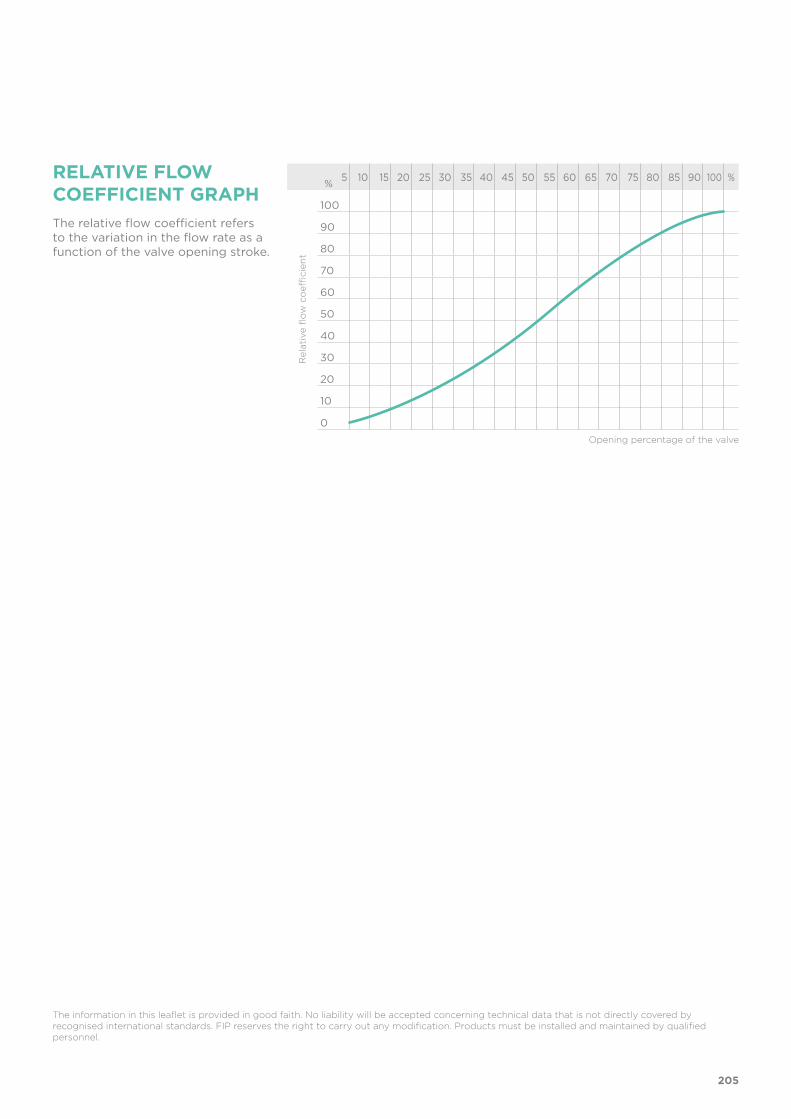
205
5 10 15 20 25 30 35 40 45 50 55 60 65 70 75 80 85 90 100 %
100
90
80
70
60
50
40
30
20
10
0
%
The relative flow coefficient refers to the variation in the flow rate as a function of the valve opening stroke.
The information in this leaflet is provided in good faith. No liability will be accepted concerning technical data that is not directly covered by recognised international standards. FIP reserves the right to carry out any modification. Products must be installed and maintained by qualified personnel.
RELATIVE FLOW COEFFICIENT GRAPH
Rel
ativ
e fl
ow
co
effici
ent
Opening percentage of the valve

206
DIMENSIONS
d DN PN B B1 H H1 L g EPDM Code FPM Code PTFE Code
20 15 10 102 25 124 80 16 460 DKDV020E DKDV020F DKDV020P
25 20 10 105 30 144 80 19 482 DKDV025E DKDV025F DKDV025P
32 25 10 114 33 154 80 22 682 DKDV032E DKDV032F DKDV032P
40 32 10 119 30 174 80 26 726 DKDV040E DKDV040F DKDV040P
50 40 10 147 35 194 120 31 1525 DKDV050E DKDV050F DKDV050P
63 50 10 172 46 224 120 38 2389 DKDV063E DKDV063F DKDV063P
75 65 10 172 46 284 120 44 2519 DKDV075E DKDV075F DKDV075P
DKDVDIALOCK® diaphragm valve with male ends for solvent welding, metric series
d DN PN B B1 H H1 L g EPDM Code FPM Code PTFE Code
20 15 10 115 25 124 80 16 490 DKLDV020E DKLDV020F DKLDV020P
25 20 10 118 30 144 80 19 512 DKLDV025E DKLDV025F DKLDV025P
32 25 10 127 33 154 80 22 712 DKLDV032E DKLDV032F DKLDV032P
40 32 10 132 30 174 80 26 756 DKLDV040E DKLDV040F DKLDV040P
50 40 10 175 35 194 120 31 1585 DKLDV050E DKLDV050F DKLDV050P
63 50 10 200 46 224 120 38 2449 DKLDV063E DKLDV063F DKLDV063P
75 65 10 200 46 284 120 44 2579 DKLDV075E DKLDV075F DKLDV075P
DKLDVDIALOCK® diaphragm valve with stroke limiter and male ends for solvent welding, metric series

207
d DN PN B B1 E H H1 LA R1 Z g EPDM Code FPM Code PTFE Code
20 15 10 102 25 41 129 80 90 1” 100 500 DKUIV020E DKUIV020F DKUIV020P
25 20 10 105 30 50 154 80 108 1” 1/4 116 562 DKUIV025E DKUIV025F DKUIV025P
32 25 10 114 33 58 168 80 116 1” 1/2 124 790 DKUIV032E DKUIV032F DKUIV032P
40 32 10 119 30 72 192 80 134 2” 140 916 DKUIV040E DKUIV040F DKUIV040P
50 40 10 147 35 79 222 120 154 2” 1/4 160 1737 DKUIV050E DKUIV050F DKUIV050P
63 50 10 172 46 98 266 120 184 2” 3/4 190 2785 DKUIV063E DKUIV063F DKUIV063P
DKUIVDIALOCK® diaphragm valve with female union ends for solvent welding, metric series
DKLUIV DIALOCK® diaphragm valve with stroke limiter and female union ends for solvent welding, metric series
d DN PN B B1 E H H1 LA R1 Z g EPDM Code FPM Code PTFE Code
20 15 10 115 25 41 129 80 90 1” 100 490 DKLUIV020E DKLUIV020F DKLUIV020P
25 20 10 118 30 50 154 80 108 1” 1/4 116 512 DKLUIV025E DKLUIV025F DKLUIV025P
32 25 10 127 33 58 168 80 116 1” 1/2 124 712 DKLUIV032E DKLUIV032F DKLUIV032P
40 32 10 132 30 72 192 80 134 2” 140 756 DKLUIV040E DKLUIV040F DKLUIV040P
50 40 10 175 35 79 222 120 154 2” 1/4 160 1585 DKLUIV050E DKLUIV050F DKLUIV050P
63 50 10 200 46 98 266 120 184 2” 3/4 190 2449 DKLUIV063E DKLUIV063F DKLUIV063P
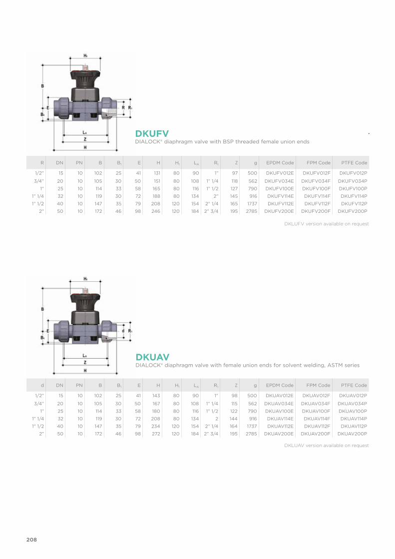
208
R DN PN B B1 E H H1 LA R1 Z g EPDM Code FPM Code PTFE Code
1/2” 15 10 102 25 41 131 80 90 1” 97 500 DKUFV012E DKUFV012F DKUFV012P
3/4” 20 10 105 30 50 151 80 108 1” 1/4 118 562 DKUFV034E DKUFV034F DKUFV034P
1” 25 10 114 33 58 165 80 116 1” 1/2 127 790 DKUFV100E DKUFV100F DKUFV100P
1” 1/4 32 10 119 30 72 188 80 134 2” 145 916 DKUFV114E DKUFV114F DKUFV114P
1” 1/2 40 10 147 35 79 208 120 154 2” 1/4 165 1737 DKUFV112E DKUFV112F DKUFV112P
2” 50 10 172 46 98 246 120 184 2” 3/4 195 2785 DKUFV200E DKUFV200F DKUFV200P
DKUFVDIALOCK® diaphragm valve with BSP threaded female union ends
DKUAVDIALOCK® diaphragm valve with female union ends for solvent welding, ASTM series
d DN PN B B1 E H H1 LA R1 Z g EPDM Code FPM Code PTFE Code
1/2” 15 10 102 25 41 143 80 90 1” 98 500 DKUAV012E DKUAV012F DKUAV012P
3/4” 20 10 105 30 50 167 80 108 1” 1/4 115 562 DKUAV034E DKUAV034F DKUAV034P
1” 25 10 114 33 58 180 80 116 1” 1/2 122 790 DKUAV100E DKUAV100F DKUAV100P
1” 1/4 32 10 119 30 72 208 80 134 2 144 916 DKUAV114E DKUAV114F DKUAV114P
1” 1/2 40 10 147 35 79 234 120 154 2” 1/4 164 1737 DKUAV112E DKUAV112F DKUAV112P
2” 50 10 172 46 98 272 120 184 2” 3/4 195 2785 DKUAV200E DKUAV200F DKUAV200P
DKLUFV version available on request
DKLUAV version available on request

209
d DN PN B B1 f F H H1 Sp U g EPDM Code FPM Code PTFE Code
20 15 10 102 25 14 65 130 80 13.5 4 690 DKOV020E DKOV020F DKOV020P
25 20 10 105 30 14 75 150 80 13.5 4 682 DKOV025E DKOV025F DKOV025P
32 25 10 114 33 14 85 160 80 14 4 972 DKOV032E DKOV032F DKOV032P
40 32 10 119 30 18 100 180 80 14 4 1186 DKOV040E DKOV040F DKOV040P
50 40 10 147 35 18 110 200 120 16 4 2100 DKOV050E DKOV050F DKOV050P
63 50 10 172 46 18 125 230 120 16 4 3159 DKOV063E DKOV063F DKOV063P
75 65 10 225 55 18 145 290 120 21 4 3619 DKOV075E DKOV075F DKOV075P
DKOVDIALOCK® diaphragm valve with fixed flanges, drilled PN10/16. Face to face according to EN 558-1
DKULVDIALOCK® diaphragm valve with female union ends for solvent welding, BS series
d DN PN B B1 E H H1 LA R1 Z g EPDM Code FPM Code PTFE Code
1/2” 15 10 102 25 41 131 80 90 1” 97 500 DKULV012E DKULV012F DKULV012P
3/4” 20 10 105 30 50 154 80 108 1” 1/4 116 562 DKULV034E DKULV034F DKULV034P
1” 25 10 114 33 58 166 80 116 1” 1/2 121 790 DKULV100E DKULV100F DKULV100P
1” 1/4 32 10 119 30 72 194 80 134 2” 142 916 DKULV114E DKULV114F DKULV114P
1” 1/2 40 10 147 35 79 222 120 154 2” 1/4 162 1737 DKULV112E DKULV112F DKULV112P
2” 50 10 172 46 98 266 120 184 2” 3/4 194 2785 DKULV200E DKULV200F DKULV200P
DKLULV version available on request
DKLOV version available on request

210
DKOAVDIALOCK® diaphragm valve with fixed flanges, drilled ANSI B16.5 cl. 150 #FF
PMDK
d DN A B C D F S Code
20 15 65 97 81 33 5.5 11 PMDK1
25 20 65 97 81 33 5.5 11 PMDK1
32 25 65 97 81 33 5.5 11 PMDK1
40 32 65 97 81 33 5.5 11 PMDK2
50 40 65 144 130 33 6.5 11 PMDK2
63 50 65 144 130 33 6.5 11 PMDK2
75 65 65 144 130 33 6.5 11 PMDK2
Wall Mounting plate
Q/BBE-LACCESSORIES
Long spigot PE100 end connectors for electrofusion or butt welding
d DN L H SDR Code
20 15 95 280 11 QBBEL11020
25 20 95 298 11 QBBEL11025
32 25 95 306 11 QBBEL11032
40 32 95 324 11 QBBEL11040
50 40 95 344 11 QBBEL11050
63 50 95 374 11 QBBEL11063
DKLOAV version available on request
d DN PN B B1 f F H H1 Sp U g EPDM Code FPM Code PTFE Code
1/2” 15 10 102 25 14 60.3 108 80 13.5 4 667 DKOAV012E DKOAV012F DKOAV012P
3/4” 20 10 105 30 15.7 69.9 150 80 13.5 4 682 DKOAV034E DKOAV034F DKOAV034P
1” 25 10 114 33 15.7 79.4 160 80 14 4 972 DKOAV100E DKOAV100F DKOAV100P
1” 1/4 32 10 119 30 15.7 88.9 180 80 14 4 1186 DKOAV114E DKOAV114F DKOAV114P
1” 1/2 40 10 147 35 15.7 98.4 200 120 16 4 2100 DKOAV112E DKOAV112F DKOAV112P
2” 50 10 172 46 19 120.7 230 120 16 4 3159 DKOAV200E DKOAV200F DKOAV200P
75 65 10 172 46 19 139.7 290 120 21 4 3619 DKOV075E DKOV075F DKOV075P

211
FASTENING AND SUPPORTINGAll valves, whether manual or actuated, must be adequately supported in many applications. The DK valve series is therefore provided with an integrated bracket that permits direct anchoring of the valve body without the need of other components.For wall installation, dedicated PMDK mounting plates which are available as accessories can be used. These plates should be fastened to the valve before wall installation. The PMDK plate also allows the DK valve to be aligned with FIP ZIKM pipe clips.
CUSTOMISATIONThe DIALOCK® DK DN 15÷65 valve can be customised using a customisation plate in white PVC. The customisation plate (B), housed in the transparent protection cap (A), can be removed and, once overturned, used for indicating identification serial numbers or service indications on the valves such as, for example, the valve function in the system, the conveyed fluid, but also specific information for customer service, such as the customer name or installation date or location on the valves. The waterproof transparent protection cap with seal O-Ring protect the customisation plate against deterioration.To access the customisation plate, make sure that the handwheel is in the release position and proceed as follows:1) Rotate the transparent protection cap fully anticlockwise (fig. 1) and
remove it by pulling upwards. If necessary, insert a screwdriver in slot (C) to make the operation easier (fig. 2).
2) Remove the plate from inside the transparent protection cap and customise as required (fig. 3).
3) Re-assemble everything making sure that the transparent protection cap O-Ring remains in its seating fig. 4).
Fig. 1
Fig. 2 Fig. 3 Fig. 4
BC
A
d DN h I j
20 15 10 25 M6
25 20 10 25 M6
32 25 10 25 M6
40 32 10 25 M6
50 40 13 44,5 M8
63 50 13 44,5 M8
75 65 13 44,5 M8

COMPONENTSEXPLODED VIEW DN 15÷50
212
DN 15 20 25 32 40 50 65
A 40 40 46 46 65 78 78
B 44 44 54 54 70 82 82
* Spare parts
** Accessories
The material of the component and the quantity supplied are indicated between brackets
1 Transparent protection cap (PVC - 1)*2 Customisation plate (PVC - 1)3 O-Ring (EPDM - 1)4 Operating mechanism (PP-GR / PVDF - 1) 5 Threaded stem - Indicator (Stainless steel - 1)
6 Compressor (IXEF® - 1)7 Diaphragm seal (EPDM, FPM, PTFE - 1)*8 Valve body (PVC-U - 1)*9 Socket seal O-ring (EPDM-FPM - 2)*10 End connector (PVC-U - 2)*11 Union nut (PVC-U - 2)*
12 Washer (Stainless steel - 4)13 Bolt (Stainless steel - 4)14 Protection plug (PE - 4)15 Distance plate (PP-GR - 1)**16 Screw (Stainless steel - 2)**

213
Fig. 5
Fig. 6
Fig. 7
DISASSEMBLY ASSEMBLY 1) Isolate the valve from the line (re-
lease the pressure and empty the pipeline).
2) If necessary, release the handwheel by pressing downwards (fig.5) and rotating anticlockwise to fully open the valve.
3) Unscrew the union nuts (11) and ex-tract the valve sideways.
4) Remove the protection plugs (14) and bolts (13) with the relative wash-ers (12).
5) Separate the valve body (8) from the internal components (4).
6) Rotate the handwheel clockwise to free the threaded stem (5), compres-sor (6) and diaphragm (7)
7) Unscrew the diaphragm (7) and re-move the shutter (6).
1) Insert the compressor (6) on the threaded stem (5) aligning it correct-ly with the reference pin on the stem.
2) Screw the diaphragm (7) on the threaded stem (5).
3) Lubricate the threaded stem (5), insert it in the operating mecha-nism (4) and rotate the handwheel anticlockwise until the stem is fully screwed in (5).
Make sure that the compressor (6) and diaphragm are correctly aligned with the housings in the operating mechanism (4) (fig. 7).
4) Fit the operating mechanism (4) on the valve body (8) and tighten the bolts (13) with the relative washers (12).
5) Tighten the bolts (13) evenly (di-agonally) to the tightening torque suggested on the relative instruction sheet.
6) Replace the protection plugs (14)7) Position the valve body between the
end connectors (10) and tighten the union nuts (11), making sure that the socket seal O-rings (9) do not exit their seats.
8) If necessary, block the handwheel by grasping it and pulling it upwards (fig. 6).
Note: during assembly, it is advisable to lubricate the threaded stem. Mineral oils are not recommended for this task as they react aggressively with EPDM rubber.

214
DE
F
Fig. 9
INSTALLATIONBefore proceeding with installation. please follow these instructions carefully: (these instructions refer to union end versions). The valve can be installed in any po-sition and in any direction.1) Check that the pipes to be connected to the valve are aligned in order to avoid
mechanical stress on the threaded joints.2) Unscrew the union nuts (11) and insert them on the pipe segments.3) Solvent weld or screw the end connectors (10) onto the pipe ends.4) Position the valve body between the end connectors, making sure that the sock-
et seal O-rings (9) do not exit their seats.5) Fully tighten the union nuts (11). 6) If necessary, support the pipework with FIP pipe clips or by means of the carrier
built into the valve itself (see paragraph “Fastening and supporting”).
LOCKING DEVICE
STROKE LIMITER
The DK valve is equipped with a DIALOCK® handwheel locking system that prevents the valve from being operated.The system can be engaged by simply lifting the handwheel once the required position has been reached (fig. 8).To release the operating mechanism, simply return the handwheel to its previous posi-tion by pushing it downwards (fig. 6).When the system is in the locked position, a lock can be installed to protect the plant against unwanted interference (fig. 9).
The DKL version of the diaphragm valve is equipped with a handwheel stroke control system which allows the minimum and maximum flows to be preset and the diaphragm to be preserved from an excessive compression during closing.The system allows the valve stroke to be modified using the two independent adjusting screws, which determine the mechanical limits of the valve during opening and closing. The valve is sold with the stroke limiters positioned such that does not limit the open-ing or closing stroke.To access and set the adjusting screws, remove the transparent protection cap (A) as previously described (see chapter “Customisation”).
Travel stop adjustment. Minimum flow rate or closed valve.1) Rotate the handwheel clockwise until the required minimum flow rate is reached or
the valve is closed.
2) Screw in nut (D) as far as it will go and lock it in this position by tightening the lock-nut (E).
To deactivate the function of limiting the closing stroke, completely unscrew nuts (D and E). In this way, the valve will fully close.
3) Re-assemble the transparent protection cap making sure that the seal O-Ring re-mains in its seating.
Stroke limiter adjustment. Maximum flow rate
1) Rotate the handwheel anticlockwise until the required maximum flow rate is reached.
2) Rotate knob (F) anticlockwise as far as the stop. The plate indicates the direction of rotation of the wheel required to obtain a higher or lower maximum flow rate.
If the opening stroke does not need to be limited, rotate the knob (F) clockwise a number of times. In this way, the valve will fully open.
3) Re-assemble the transparent protection cap making sure that the seal O-Ring re-mains in its seating.
FREE LOCK
Note: Before putting the valve into service, check that the bolts on the valve body (13) are tightened correctly at the suggested torque.


VM DN 80÷100 PVC-U
Diaphragm valve

218
Technical specificationsConstruction Single wear diaphragm valveSize range DN 80 ÷ 100
Nominal pressure PN 10 with water at 20° CPN 6 with water at 20° C (PTFE version)
Temperature range 0 °C ÷ 60 °CCoupling standards Solvent welding: EN ISO 1452, EN ISO 15493, BS 4346-1,
DIN 8063, NF T54-028, ASTM D 2467, JIS K 6743.Can be coupled to pipes according to EN ISO 1452, EN ISO 15493
Flanging system: ISO 7005-1, EN ISO 1452, EN ISO 15493, EN 558-1, DIN 2501, ANSI B16.5 Cl.150
Reference standards Construction criteria: EN ISO 16138, EN ISO 1452, EN ISO 15493Test methods and requirements: ISO 9393Installation criteria: DVS 2204, DVS 2221, UNI 11242
Valve material Body: PVC-UBonnet: PP-GRHandwheel: PA-GR
Diaphragm material EPDM, FPM, PTFE (on request NBR)Control options Manual control; pneumatic actuator
VM
The VM is particularly suitable for shutting off and regulating abrasive or dirty fluids. The handwheel control and diaphragm seal provide precise and effective control, while reducing the risk of water hammer to a minimum.
DIAPHRAGM VALVE
• Connection system for solvent weld, threaded and flanged joints • Compact and lightweight construction• High flow coefficient and minimum pressure drop• Internal components in metal totally isolated from the conveyed fluid,
with anti-friction disk to reduce friction to a minimum• Modularity of the range: only 5 diaphragm and bonnet sizes for 9 differ-
ent valve sizes• Handwheel that stays at the same height during rotation
DN 80÷100

219
1 Handwheel in (PA-GR) with high mechanical strength and ergonomic grip for optimum manageability
2 Metal optical position indicator supplied as standard
3 Full protection bonnet in PP-GR
Internal circular and symmetrical diaphragm sealing area
4 Diaphragm available in EPDM, FPM, PTFE (NBR on request) and easy to replace
5 Threaded metal inserts for anchoring the valve
1
3
5
2
4

220
TECHNICAL DATA
-40 -20 0 20 40 60 80 100 120 140 °C
16
14
12
10
8
6
4
2
0
Wo
rkin
g p
ress
ure
Working temperature
barPRESSURE VARIATION ACCORDING TO TEMPERATURE
For water and harmless fluids to which the material is classified as CHEMICALLY RESISTANT. In other cases, a reduction of the nominal pressure PN is required (25 years with safety factor).
DN 80 100
Kv100 l/min 2000 2700
KV100 FLOW COEFFICIENTThe Kv100 flow coefficient is the Q flow of litres per minute of water at a temperature of 20°C that will generate ∆p= 1 bar pressure drop at a certain valve position.The Kv100 values shown in the table are calculated with the valve completely open.
The information in this leaflet is provided in good faith. No liability will be accepted concerning technical data that is not directly covered by recognised international standards. FIP reserves the right to carry out any modification. Products must be installed and maintained by qualified personnel.
PRESSURE DROP GRAPH
bar1 10 100 1000 10000 l/min
1
0.1
0.01
0.001
DN
80
DN
100
Pre
ssu
re d
rop
Flow rate
PTFE
EPDM/FPM

221
DIMENSIONS
d DN PN B B1 H h H1 I J L g EPDM Code FPM Code PTFE Code
90 80 *10 225 55 300 23 200 100 M12 51 7000 VMDV090E VMDV090F VMDV090P
110 100 *10 295 69 340 23 250 120 M12 61 10500 VMDV110E VMDV110F VMDV110P
VMDVDiaphragm valve with male ends for solvent welding, metric series
*PTFE PN6
d DN PN B B1 F f H H1 I J Sp U g EPDM Code FPM Code PTFE Code
90 80 *10 225 55 160 18 310 200 100 M12 21.5 8 8500 VMOV090E VMOV090F VMOV090P
110 100 *10 295 69 180 18 350 250 120 M12 22.5 8 12400 VMOV110E VMOV110F VMOV110P
VMOVDiaphragm valve with fixed flanges, drilled PN10/16. Face to face according to EN 558-1
*PTFE PN6

222
VMOAVDiaphragm valve with fixed flanges, drilled ANSI B16.5 cl. 150 #FF
*PTFE PN6
d PN B B1 F f H H1 I J Sp U g EPDM Code FPM Code PTFE Code
3” *10 225 55 152.4 19.1 310 200 100 M12 21.5 4 8500 VMOAV300E VMOAV300F VMOAV300P
4” *10 295 69 190.5 19.1 350 250 120 M12 22.5 8 12400 VMOV110E VMOV110F VMOV110P

COMPONENTSEXPLODED VIEW
1 Bonnet (PP-GR - 1); Handwheel (PA-GR - 1)2 Indicator - stem (STAINLESS steel - 1)3 Shutter (PBT - 1)
4 Diaphragm (EPDM, FPM, PTFE - 1)5 Body (PVC-U - 1)6 Hexagonal screw (Zinc plated steel - 4)
7 Washer (Zinc plated steel - 4)8 Protection plug (PE - 4)9 Nut (Zinc plated steel - 4)
DN 100DN 80
223
DN 80 100
A 114 193
B 127 -
The component material and quantity supplied are indicated in the parentheses.

DISMOUNTING ASSEMBLYThe diaphragm constitutes the part of the valve more subject to mechani-cal and chemical stress from the fluid. Consequently, the condition of the di-aphragm must be checked at regular intervals in accordance with the service conditions. To do this, it must be discon-nected from the handwheel and from the valve body.1) Cut-off fluid upstream from the valve
and make sure it is de-pressurised (downstream drain if necessary).
2) Unscrew the four screws (6) and separate the body (5) from the inter-nal components.
3) Unscrew the diaphragm (4) from the shutter (3). Rotate the handwheel clockwise to free the stem-shutter unit. Clean or replace the diaphragm, if necessary (4). If necessary, lubricate the stem (2).
1) Apply the shutter (3) to the stem (2), ensuring the stem pin is positioned correctly.
2) Screw the diaphragm (4) onto the stem (2), taking care not to stretch it.
3) Open the valve.4) Place the bonnet-handwheel unit (1)
on the body (5) and join the two com-ponents with bolts.
5) Press the protection plugs into place (8).
INSTALLATIONThe valve can be installed in any position and in any direction.When starting up the plant, make sure that there are no leaks from between the dia-phragm and the valve body. If necessary, tighten the fastening screws (6).
Note: during assembly operations, it is advisable to lubricate the threaded stem. Mineral oils are not recommended for this task as they react aggressively with EPDM rubber.Moreover, as the diaphragm seal is compressed between the body and the actuator, the valve body stud-bolts and nuts must be checked and tightened, if necessary, pri-or to installation.
224


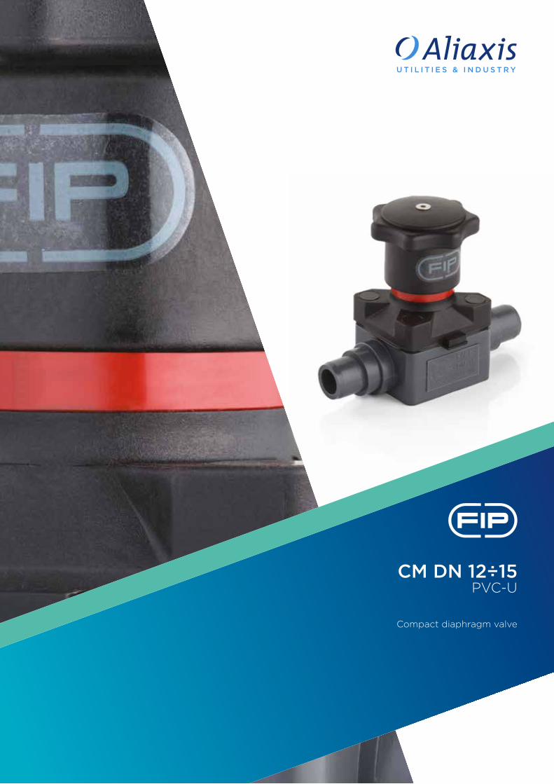
CM DN 12÷15PVC-U
Compact diaphragm valve

228
Technical specificationsConstruction Compact single wear diaphragm valveSize range DN 12÷15Nominal pressure PN 6 with water at 20 °CTemperature range 0 °C ÷ 60 °CCoupling standards Solvent welding: EN ISO 1452, EN ISO 15493, BS 4346-
1, DIN 8063, NF T54-028, ASTM D 2467, JIS K 6743.Can be coupled to pipes according to EN ISO 1452, EN ISO 15493, DIN 8062, NF T54-016, ASTM T 1785, JIS K 6741
Thread: ISO 228-1, DIN 2999, ASTM D 2464, JIS B 0203
Reference standards Construction criteria: EN ISO 16138, EN ISO 1452, EN ISO 15493Test methods and requirements: ISO 9393Installation criteria: DVS 2204, DVS 2221, UNI 11242
Valve material Body: PVC-UBonnet and handwheel: PA-GR
Diaphragm material EPDM, FPM, PTFEControl options Manual control; pneumatic actuator
CM
The CM is a manually operated diaphragm valve of reduced dimensions and particularly compact structure, ideal for use in confined spaces.
COMPACT DIAPHRAGM VALVE
• Connection system for solvent weld and threaded joints • Extremely compact construction • Internal operating components in metal totally isolated from the
conveyed fluid• Valve stem in STAINLESS steel • Compressor with floating diaphragm support• Easy to replace diaphragm seal• Corrosion-proof internal components• CDSA (Circular Diaphragm Sealing Angle) system offering the following
advantages:- uniform distribution of shutter pressure on the diaphragm seal- reduction in the tightening torque of the screws fixing the actuator to
the valve body- reduced mechanical stress on all valve components (actuator, body and
diaphragm)- easy to clean valve interior- low risk of the accumulation of deposits, contamination or damage to the
diaphragm due to crystallisation- operating torque reduction
DN 12÷15

229
1 Handwheel in PA-GR, completely sealed, high mechanical strength with ergonomic grip for optimum manageability
2 Integrated adjustable torque limiter designed to prevent excessive compression of the diaphragm and always guarantee a minimum fluid flow
3 Optical position indicator supplied as standard
4 Bonnet in PA-GR with STAINLESS steel nuts fully protected by plastic plugs to eliminate zones where impurities may accumulate. Internal circular and symmetrical diaphragm sealing area
5 STAINLESS steel bolts, can also be inserted from above
6 Threaded metal inserts for anchoring the valve
1
2
3
6
5
4

Flow Rate
230
TECHNICAL DATA
-40 -20 0 20 40 60 80 100 120 140 °C
16
14
12
10
8
6
4
2
0
Wo
rkin
g p
ress
ure
Working temperature
barPRESSURE VARIATION ACCORDING TO TEMPERATUREFor water and non-hazardous fluids with regard to which the material is classified as CHEMICALLY RESISTANT. In other cases, a reduction of the nominal pressure PN is required (25 years with safety factor).
DN 12 15
Kv100 l/min 47 60
KV100 FLOW COEFFICIENTThe Kv100 flow coefficient is the Q flow rate of litres per minute of water at a temperature of 20°C that will generate ∆p= 1 bar pressure drop at a certain valve position.The Kv100 values shown in the table are calculated with the valve completely open.
The information in this leaflet is provided in good faith. No liability will be accepted concerning technical data that is not directly covered by recognised international standards. FIP reserves the right to carry out any modification. Products must be installed and maintained by qualified personnel.
PRESSURE DROP GRAPH
Pre
ssu
re d
rop
bar1 10 100 1000 10000 l/min
1
0.1
0.01
0.001
DN
12D
N 15

Flow Rate
231
d DN PN B max B1 H h H1 I J L g EPDM Code FPM Code PTFE Code
20 15 6 86 15 124 8 58.5 35 M5 17 310 CMDV020E CMDV020F CMDV020P
d DN PN B max B1 H h H1 I J L g EPDM Code FPM Code PTFE Code
16 12 6 86 15 75 8 58.5 35 M5 14 270 CMIV016E CMIV016F CMIV016P
20 15 6 86 15 75 8 58.5 35 M5 16 270 CMIV020E CMIV020F CMIV020P
CMDVCompact diaphragm valve with male ends for solvent welding, metric series
CMIVCompact diaphragm valve with female ends for solvent welding, metric series
DIMENSIONS

232
d DN PN B max E H h H1 I J LA R1 Z g EPDM Code FPM Code PTFE Code
20 15 6 86 41 129.5 8 58.5 35 M5 90 1” 97.5 285 CMUIV020E CMUIV020F CMUIV020P
CMUIVCompact diaphragm valve with female union ends for solvent welding, metric series
R DN PN B max B1 H h H1 I J L g EPDM Code FPM Code PTFE Code
3/8” 12 6 86 15 75 8 58.5 35 M5 11.5 270 CMFV038E CMFV038F CMFV038P
1/2” 15 6 86 15 75 8 58.5 35 M5 15 270 CMFV012E CMFV012F CMFV012P
CMFVCompact diaphragm valve with BSP threaded female ends

233
R DN PN B max E H h H1 I J LA R1 Z g EPDM Code FPM Code PTFE Code
1/2” 15 6 86 41 129.5 8 58.5 35 M5 90 1” 97.5 285 CMUFV012E CMUFV012F CMUFV012P
CMUFVCompact diaphragm valve with BSP threaded female union ends unions

The material of the component and the quantity supplied are indicated between brackets
234
COMPONENTSEXPLODED VIEW
1 Body (PVC-U - 1)2 Diaphragm seal (EPDM, FPM, PTFE - 1)5 Fastening screw (STAINLESS steel - 4)6 Washer (STAINLESS steel - 4)7 Shutter (PA-GR - 1)8 Nut (STAINLESS steel - 1)
9 Stem (STAINLESS steel - 1)10 Bonnet (PA-GR - 1)13 Nut (STAINLESS steel - 4)14 Protection plug (POM - 4)15 Optical position indicator (PVDF - 1)22 O-Ring (NBR - 1)
23 Handwheel (PA-GR - 1)24 O-Ring (NBR - 1)25 Bonnet (PA-GR - 1)26 Fastening screw (STAINLESS steel - 1)

DISMOUNTING MOUNTINGIf the valve is already installed on the line, shut-off the fluid flow upstream and make sure that there is no pressure. If necessary, fully drain the system downstream. If there are hazardous fluids present, drain and ventilate the valve.The diaphragm constitutes the part of the valve more subject to mechanical and chemical stress from the fluid. Consequently, the condition of the diaphragm must be checked at regular intervals in accordance with the service conditions. To do this, it must be disconnected from the handwheel and from the valve body.1) Unscrew the four screws (5) and
separate the body (1) from the internal components.
2) Unscrew the diaphragm seal (2) from the shutter (7).
3) If necessary, clean or replace the diaphragm seal (2).
4) If necessary, lubricate the stem (9).
1) The diaphragm seal (2) must be screwed fully into the compressor (7) in a clockwise direction. If necessary, unscrew slightly in an anticlockwise direction to line up the screw holes.
2) Fix the bonnet (10) to the body (1) using screws (5). Tighten the screws, making sure not to over-compress the diaphragm.
INSTALLATIONThe valve can be installed in any position and in any direction.When starting up the plant, make sure that there are no leaks from between the diaphragm and the valve body. If necessary, tighten the fastening screws (5).
SETTINGThe valve is factory set to guarantee a permanent seal without requiring any further intervention. To adjust the setting, rotate the handwheel to the required minimum opening position, remove screw (26) using a hex key.Remove the bonnet (25) and rotate the handwheel (23) clockwise until a resistance to the rotation is felt.If necessary, replace the O-Ring (24) in its seating and re-insert the bonnet(25) in the handwheel: the double D connection must fit over the stem (9) and, with a slight twisting action, align the ribs in the bonnet with those in the handwheel. Tighten screw (26) to a sufficiently high torque value. Each turn of the handwheel corresponds to 1.75mm travel.
235


VM/RM DN 8÷15PVC-U
Mini-diaphragm and diaphragm cock valve

238
Technical specificationsConstruction VM: Mini-diaphragm valve
RM: diaphragm cock valveSize range VM: DN 8 (1/4”)
RM: DN 15
Nominal pressure VM: PN 10 with water at 20 °CRM: PN 4 with water at 20 °C
Temperature range 0 °C ÷ 60 °CCoupling standards Solvent welding: EN ISO 1452, EN ISO 15493.
Can be coupled to pipes according to EN ISO 1452, EN ISO 15493Thread: UNI ISO 228-1, DIN 2999
Reference standards Construction criteria: EN ISO 16138, EN ISO 1452, EN ISO 15493Test methods and requirements: ISO 9393Installation criteria: DVS 2204, DVS 2221, UNI 11242
Valve material PVC-UDiaphragm material EPDMControl options Manual control
VM/RM
The VM mini-valve and RM diaphragm cock valve are both used to shut-off and regulate fluid flow and are characterised by their reduced size.
MINI-DIAPHRAGM VALVE
DIAPHRAGM COCK VALVE
• Connection system for solvent weld and threaded joints • Extremely compact dimensions • Can be installed in any position• Valve material compatibility (PVC-U) and elastomer seal elements
(EPDM), with water, drinking water and other food substances as per current regulations
• Specifically designed for laboratory applications or for sampling purposes
• Connection system for threaded joints • Can be installed in any position• Can be coupled to pipes in PVC-U, PVC-U plasticised, PE and rubber• Valve material compatibility (PVC-U) with water, drinking water and other
food substance conveyance according to current regulations • Specifically designed for laboratory applications or for sampling purposes
DN 8÷15
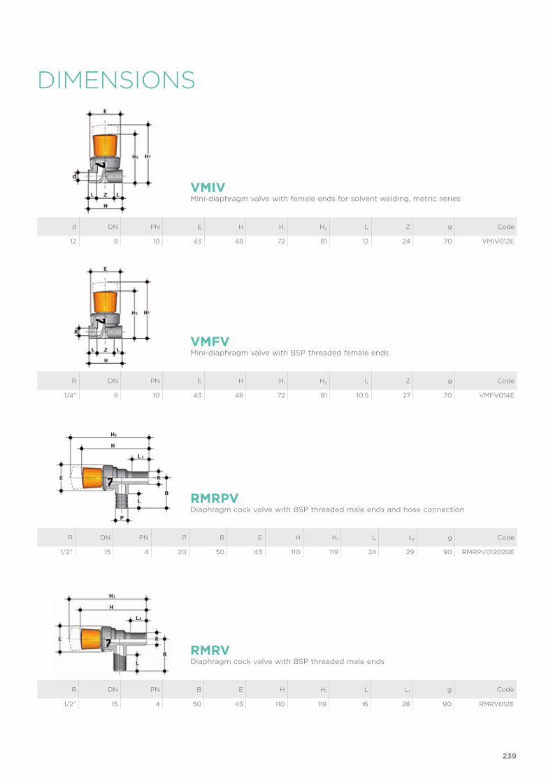
DIMENSIONS
d DN PN E H H1 H2 L Z g Code
12 8 10 43 48 72 81 12 24 70 VMIV012E
R DN PN B E H H1 L L1 g Code
1/2” 15 4 50 43 110 119 16 28 90 RMRV012E
VMIVMini-diaphragm valve with female ends for solvent welding, metric series
RMRVDiaphragm cock valve with BSP threaded male ends
R DN PN E H H1 H2 L Z g Code
1/4” 8 10 43 48 72 81 10.5 27 70 VMFV014E
VMFVMini-diaphragm valve with BSP threaded female ends
R DN PN P B E H H1 L L1 g Code
1/2” 15 4 20 50 43 110 119 24 29 90 RMRPV012020E
RMRPVDiaphragm cock valve with BSP threaded male ends and hose connection
239

COMPONENTSEXPLODED VIEW
VM DN 8 RM DN 15
1 Screw (STAINLESS steel - 1)2 Handwheel (PVC-U - 1)3 Bonnet (PVC-U - 1)
The material of the component and the quantity supplied are indicated between brackets
4 Stem (PVC-U - 1)5 Sleeve (POM - 1)6 Split couplings (POM - 2)
7 Diaphragm (EPDM- 1)8 Body (PVC-U - 1)
240

DISMOUNTING MOUNTING1) Isolate the mini-valve or cock valve
from the fluid.2) Unscrew the bonnet (3) clockwise.3) Unscrew screw (1) and remove the
handwheel (2).4) Remove the stem (4) to access the
split couplings (6), the sleeve (5) and diaphragm (7)
1) Assemble the two split couplings (6), the sleeve (5) and diaphragm (7) to the stem (4), making sure that the latter is inserted in the larger cavity of each half collar, while the diaphragm connection is inserted in the smaller cavity
2) Screw the stem (4) to the bonnet (3)3) Position the handwheel (2) on the
bonnet and tighten the screw (1)4) Screw the bonnet to the body (8)
Note: during assembly operations, it is advisable to lubricate the rubber seals. Mineral oils are not recommended for this task as they react aggressively with EPDM rubber.
INSTALLATIONThe mini-valve and cock valve can be installed in any position. If the valve is installed in a vertical position, if the connection is solvent welded, make sure that the solvent cement does not enter inside the body, as this would damage the seating of the seal.
241


RV DN 10÷100PVC-U
Sediment strainer

244
Technical specificationsConstruction Sediment strainerSize range DN 10÷100Nominal pressure PVC-U Grey
DN 10÷50: PN 16 with water at 20 °CDN 65: PN 10 with water at 20 °CDN 80÷100: PN 6 with water at 20 °C
PVC-U TransparentDN 10÷25: PN 16 with water at 20 °CDN 32÷50: PN 10 with water at 20 °CDN 65: PN 6 with water at 20 °CDN 80÷100: PN 4 with water at 20 °C
Temperature range 0 °C ÷ 60 °CCoupling standards Solvent welding: EN ISO 1452, EN ISO 15493, BS 43461,
DIN 8063, NF T54-028, ASTM D 2467, JIS K 6743. Can be coupled to pipes according to EN ISO 1452, EN ISO 15493, DIN 8062, NF T54-016, ASTM D 1785, JIS K 6741
Thread: UNI ISO 228-1, DIN 2999, ASTM D 2467, JIS B 0203
Flanging system:: ISO 7005-1, EN ISO 1452, EN ISO 15493, EN 558-1 (DN 10÷50), DIN 2501, ANSI B.16.5 cl.150, JIS B 2220
Reference standards Construction criteria: EN ISO 1452, EN ISO 15493,Test methods and requirements: ISO 9393Installation criteria: DVS 2204, DVS 2221, UNI 11242
Valve material Body: PVC-U grey or transparentStrainer: PVC-U or STAINLESS steel
Seal material EPDM or FPM
RV
The RV Sediment strainer limits the passage of any solid particles present in the fluid by means of a strainer.
SEDIMENT STRAINER
• Connection system for solvent weld, threaded and flanged joints • Strainer mounted on an easily removed support that facilitates the clean-
ing or replacement • Valve material compatibility (PVC-U) with water conveyance, drinking
water and other food substances according to current regulations• Can be maintained with the valve body installed
DN 10÷100

245
TECHNICAL DATA
-40 -20 0 20 40 60 80 100 120 140 °C
16
14
12
10
8
6
4
2
0
Wo
rkin
g p
ress
ure
Working temperature
barPRESSURE VARIATION ACCORDING TO TEMPERATURE
For water and non-hazardous fluids with regard to which the material is classified as CHEMICALLY RESISTANT. In other cases, a reduction of the nominal pressure PN is required (25 years with safety factor).
PRESSURE DROP GRAPH
KV100 FLOW COEFFICIENTThe Kv100 flow coefficient is the Q flow rate of litres per minute of water at a temperature of 20°C that will generate ∆p= 1 bar pressure drop at a certain valve position.The Kv100 values shown in the table are calculated with the valve completely open.
DN 10 15 20 25 32 40 50 65 80 100
Kv100 l/min 22 40 70 103 188 255 410 650 1050 1700
Pre
ssu
re d
rop
Flow Rate
bar1 10 100 1000 10000 l/min
1
0.1
0.01
0.001
DN
15
DN
10
DN
20
DN
25
DN
32
DN
40
DN
50
DN
65
DN
80
DN
100

246
The information in this leaflet is provided in good faith. No liability will be accepted concerning technical data that is not directly covered by recognised international standards. FIP reserves the right to carry out any modification. Products must be installed and maintained by qualified personnel.
Pitch (mm) 0.7 1.0 1.5 2.0 2.5
number of holes per cm2 240 190 100 60 35
ASTM series equivalent in strainer 35 50 35 30 18
ø equivalent hole µm 370 300 500 600 900
strainer material STAINLESS STEEL PVC-U PVC-U PVC-U PVC-U
DN 10 15 20 25 32 40 50 65 80 100
Atot 16 16 23.5 36 53 69 101 197 247 396
TOTAL STRAINER AREA Atot (cm2)
STRAINER DIMENSIONS

R DN PNRVUFV
PNRVUFT A max B E H L Z Fig. g Code RVUFV Code RVUFT
3/8” 10 16 16 125 72 55 135 11.4 112.2 A 206 RVUFV038E RVUFT038E
1/2” 15 16 16 125 72 55 142 15 112 A 210 RVUFV012E RVUFT012E
3/4” 20 16 16 145 84 66 159 16.3 126.4 A 355 RVUFV034E RVUFT034E
1” 25 16 16 165 95 75 183 19.1 144.8 A 522 RVUFV100E RVUFT100E
1”1/4 32 16 10 190 111 87 214 21.4 171.2 A 742 RVUFV114E RVUFT114E
1”1/2 40 16 10 210 120 100 235 21.4 192.2 A 1106 RVUFV112E RVUFT112E
2” 50 16 10 240 139 120 285 25.7 233.6 A 1873 RVUFV200E RVUFT200E
DIMENSIONS
d DN PNRVUIV
PNRVUIT A max B E H L Z Fig. g Code RVUIV Code RVUIT
16 10 16 16 125 72 55 135 14 107 A 203 RVUIV016E RVUIT016E
20 15 16 16 125 72 55 135 16 103 A 211 RVUIV020E RVUIT020E
25 20 16 16 145 84 66 158 19 120 A 358 RVUIV025E RVUIT025E
32 25 16 16 165 95 75 176 22 132 A 526 RVUIV032E RVUIT032E
40 32 16 10 190 111 87 207 26 155 A 733 RVUIV040E RVUIT040E
50 40 16 10 210 120 100 243 31 181 A 1095 RVUIV050E RVUIT050E
63 50 16 10 240 139 120 298 38 222 A 1843 RVUIV063E RVUIT063E
d DN PNRVIV
PNRVIT A max B E H K L Z Fig. g Code RVIV Code RVIT
75 65 10 6 300 179 104 243 96 33 155 B 2385 RVIV075E RVIT075E
90 80 6 4 325 192 116 262 105 37 160 B 2975 RVIV090E RVIT090E
110 100 6 4 385 231 138 325 - 61 203 C 4610 RVIV110E RVIT110E
RVUIV-RVUITRVUIV PVC-U rigid - RVUIT PVC-U transparentSediment strainer with female union ends for solvent welding
RVIV-RVITRVIV PVC-U rigid - RVIT PVC-U transparentSediment strainer with female ends for solvent welding
RVUFV-RVUFTRVUFV PVC-U rigid - RVUFT PVC-U transparentSediment strainer with BSP threaded female union ends
also available with standard JIS connections
also available with standard ASTM/NPT connections
247
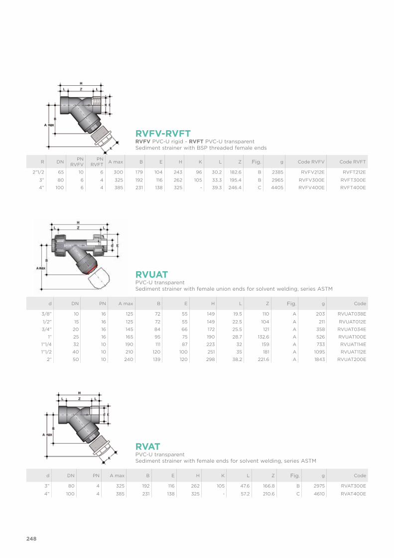
d DN PN A max B E H L Z Fig. g Code
3/8” 10 16 125 72 55 149 19.5 110 A 203 RVUAT038E
1/2” 15 16 125 72 55 149 22.5 104 A 211 RVUAT012E
3/4” 20 16 145 84 66 172 25.5 121 A 358 RVUAT034E
1” 25 16 165 95 75 190 28.7 132.6 A 526 RVUAT100E
1”1/4 32 10 190 111 87 223 32 159 A 733 RVUAT114E
1”1/2 40 10 210 120 100 251 35 181 A 1095 RVUAT112E
2” 50 10 240 139 120 298 38.2 221.6 A 1843 RVUAT200E
d DN PN A max B E H K L Z Fig. g Code
3” 80 4 325 192 116 262 105 47.6 166.8 B 2975 RVAT300E
4” 100 4 385 231 138 325 - 57.2 210.6 C 4610 RVAT400E
R DN PNRVFV
PNRVFT A max B E H K L Z Fig. g Code RVFV Code RVFT
2”1/2 65 10 6 300 179 104 243 96 30.2 182.6 B 2385 RVFV212E RVFT212E
3” 80 6 4 325 192 116 262 105 33.3 195.4 B 2965 RVFV300E RVFT300E
4” 100 6 4 385 231 138 325 - 39.3 246.4 C 4405 RVFV400E RVFT400E
RVFV-RVFT
RVUAT
RVAT
RVFV PVC-U rigid - RVFT PVC-U transparent Sediment strainer with BSP threaded female ends
PVC-U transparent Sediment strainer with female union ends for solvent welding, series ASTM
PVC-U transparent Sediment strainer with female ends for solvent welding, series ASTM
248

R DN PN A max B E H L Z Fig. g Code
3/8” 10 16 125 72 55 135 13.7 107.6 A 206 RVUNT038E
1/2” 15 16 125 72 55 143 17.8 107.4 A 210 RVUNT012E
3/4” 20 16 145 84 66 159 18 123 A 355 RVUNT034E
1” 25 16 165 95 75 183 22.6 137.8 A 522 RVUNT100E
1”1/4 32 10 190 111 87 214 25.1 163.8 A 742 RVUNT114E
1”1/2 40 10 210 120 100 235 24.7 185.6 A 1106 RVUNT112E
2” 50 10 240 139 120 285 29.6 225.8 A 1873 RVUNT200E
RVUNTPVC-U transparent Sediment strainer with NPT threaded female union ends
R DN PN A max B E H K L Z Fig. g Code
3” 80 4 325 192 116 262 105 51 160 B 2965 RVNT300E
4” 100 4 385 231 138 325 - 61 203 C 4405 RVNT400E
RVNTPVC-U transparent Sediment strainer with NPT threaded female ends
d DN PNRVDV
PNRVDT A max B H L Fig. g Code RVDV Code RVDT
16 10 16 10 125 72 114 14 A 110 RVDV016E RVDT016E
20 15 16 10 125 72 124 16 A 120 RVDV020E RVDT020E
25 20 16 10 145 84 144 19 A 190 RVDV025E RVDT025E
32 25 16 10 165 95 154 22 A 285 RVDV032E RVDT032E
40 32 16 10 190 111 174 26 A 400 RVDV040E RVDT040E
50 40 16 10 210 120 194 31 A 600 RVDV050E RVDT050E
63 50 16 10 240 139 224 38 A 945 RVDV063E RVDT063E
RVDV-RVDTRVDV PVC-U rigid - RVDT PVC-U transparentSediment strainer with male ends for solvent welding
249

d DN PNRVOV
PNRVOT A max B F f H Fig. g Code RVOV Code RVOT
20 15 16 10 125 72 65 14 130 A 260 RVOV020E RVOT020E
25 20 16 10 145 84 75 14 150 A 395 RVOV025E RVOT025E
32 25 16 10 165 95 85 14 160 A 560 RVOV032E RVOT032E
40 32 16 10 190 111 100 18 180 A 850 RVOV040E RVOT040E
50 40 16 10 210 120 110 18 200 A 1170 RVOV050E RVOT050E
63 50 16 10 240 139 125 18 230 A 1760 RVOV063E RVOT063E
75 65 10 6 300 179 145 17 356 B 3600 RVOV075E RVOT075E
90 80 6 4 325 192 160 17 404 B 4910 RVOV090E RVOT090E
110 100 6 4 385 231 180 17 475 C 6790 RVOV110E RVOT110E
d DN PNRVOAV
PNRVOAT A max B F f H Fig. g Code RVOAV Code RVOAT
1/2” 15 16 10 125 72 60.3 15.9 130 A 260 RVOAV012E RVOAT012E
3/4” 20 16 10 145 84 69.9 15.9 150 A 395 RVOAV034E RVOAT034E
1” 25 16 10 165 95 79.4 15.9 160 A 560 RVOAV100E RVOAT100E
1”1/4 32 16 10 190 111 88.9 15.9 180 A 850 RVOAV114E RVOAT114E
1”1/2 40 16 10 210 120 98.4 15.9 200 A 1170 RVOAV112E RVOAT112E
2” 50 16 10 240 139 120.7 19.1 230 A 1760 RVOAV200E RVOAT200E
2”1/2 65 10 6 300 179 139.7 19.1 356 B 3600 RVOV075E RVOT075E
3” 80 6 4 325 192 152.4 19.1 404 B 4910 RVOV090E RVOT090E
4” 100 6 4 385 231 190.5 19.1 475 C 6790 RVOV110E RVOT110E
RVOV-RVOT
RVOAV-RVOAT
RVOV PVC-U rigid - RVOT PVC-U transparentSediment strainer with fixed flanges, drilled PN10/16
RVOAV PVC-U rigid - RVOAT PVC-U transparentSediment strainer with fixed flanges, drilled ANSI B16.5 cl.150 #FF
250

COMPONENTSEXPLODED VIEW
1 Body (PVC-U - 1)2 Strainer (PVC-U/STAINLESS steel - 1)*3 Bonnet (PVC-U - 1)4 Strainer support (PVC-U - 1)5 A-B O-ring (EPDM-FPM - 1)*5 C O-ring (EPDM-FPM - 2)
* Spare parts
The material of the component and the quantity supplied are indicated between brackets
6 Washer (PVC-U - 1)7 Union nut (PVC-U - 1)8 Retaining ring (PVC-U - 1)9 Socket seal O-Ring (EPDM-FPM - 2)*
10 End connector (PVC-U - 2)*11 Union nut (PVC-U - 2)
DN 15 ÷ 50 DN 65 ÷ 80 DN 100
251
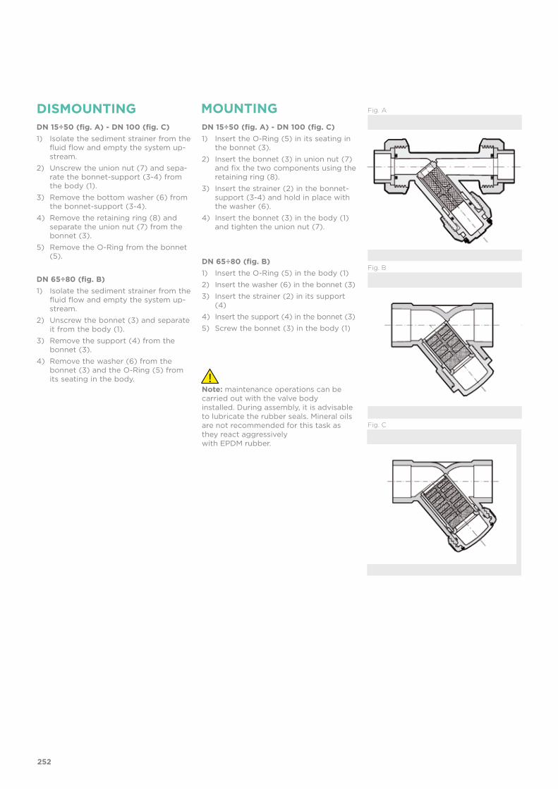
DN 15÷50 (fig. A) - DN 100 (fig. C)1) Insert the O-Ring (5) in its seating in
the bonnet (3).2) Insert the bonnet (3) in union nut (7)
and fix the two components using the retaining ring (8).
3) Insert the strainer (2) in the bonnet-support (3-4) and hold in place with the washer (6).
4) Insert the bonnet (3) in the body (1) and tighten the union nut (7).
DN 65÷80 (fig. B)1) Insert the O-Ring (5) in the body (1)2) Insert the washer (6) in the bonnet (3)3) Insert the strainer (2) in its support
(4)4) Insert the support (4) in the bonnet (3)5) Screw the bonnet (3) in the body (1)
DISMOUNTING MOUNTINGDN 15÷50 (fig. A) - DN 100 (fig. C)1) Isolate the sediment strainer from the
fluid flow and empty the system up-stream.
2) Unscrew the union nut (7) and sepa-rate the bonnet-support (3-4) from the body (1).
3) Remove the bottom washer (6) from the bonnet-support (3-4).
4) Remove the retaining ring (8) and separate the union nut (7) from the bonnet (3).
5) Remove the O-Ring from the bonnet (5).
DN 65÷80 (fig. B)1) Isolate the sediment strainer from the
fluid flow and empty the system up-stream.
2) Unscrew the bonnet (3) and separate it from the body (1).
3) Remove the support (4) from the bonnet (3).
4) Remove the washer (6) from the bonnet (3) and the O-Ring (5) from its seating in the body.
Note: maintenance operations can be carried out with the valve bodyinstalled. During assembly, it is advisable to lubricate the rubber seals. Mineral oils are not recommended for this task as they react aggressivelywith EPDM rubber.
Fig. C
Fig. B
Fig. A
252

INSTALLATIONThe sediment strainer can be installed in any position, making sure that the arrow stamped on the body indicates the direction of fluid flow and that the strainer part is facing downwards. To avoid damaging the strainer, appropriate devices must be installed on the line to prevent backflow.
DN 15÷50 (fig. A)1) Unscrew the union nuts (11) and slide them onto the pipe.2) Heat weld the end connectors (10) onto the pipe segments.3) Position the sediment strainer between the end connectors4) Tighten the union nuts.
DN 65÷80 (fig. B) and DN 100 (fig. C)The joint must be made by solvent welding the pipe directly into the socket of the valve body.
WARNINGS- sediment strainers with a transparent body allow the passage of light, thus promot-
ing the internal growth of algae and micro-organisms.- sediment strainers with a transparent body are not protected against solar rays. Use
in an open-air system will accelerate the ageing process of the material and reduce its working life.
- The sediment strainers with a transparent body located near pumps should be pro-tected against vibrations.
- Always check the cleanliness of the strainer elements.
253


VV DN 10÷50PVC-U
Angle seat valve

256
Technical specificationsConstruction Angle seat shutting-off and regulating valve Size range DN 10 ÷ 50 Nominal pressure DN 10÷25: PN 16 with water at 20 °C
DN 32÷50: PN 10 with water at 20 °CTemperature range 0 °C ÷ 60 °CCoupling standards Solvent welding: EN ISO 1452, EN ISO 15493, BS 4346-
1, DIN 8063, NF T54-028, ASTM D 2467, JIS K 6743. Can be coupled to pipes according to EN ISO 1452, EN ISO 15493, DIN 8062, NF T54-016, ASTM D 1785, JIS K 6741
Thread: ISO 228-1, DIN 2999, ASTM D 2467, JIS B 0203
Flanging system: ISO 7005-1, EN ISO 1452, EN ISO 15493, EN 558-1 (DN 10÷50), DIN 2501, ANSI B16.5 Cl. 150, JIS B 2220
Reference standards Construction criteria: EN ISO 1452, EN ISO 15493Test methods and requirements: ISO 9393Installation criteria: DVS 2204, DVS 2221, UNI 11242
Valve material PVC-USeal material EPDM+PE (EPDM+PTFE or FPM+PTFE on request)Control options Manual control
VV
The VV angle seat valve isa shutting-off and regulating valve particularly suitable for clean fluids.
ANGLE SEAT VALVE
• Connection system for solvent weld, threaded and flanged joints • Can be installed in any position • No metal parts in contact with the fluid• Valve material compatibility (PVC-U) with water, drinking water and other
food substance conveyance according to current regulations • Can be maintained with the valve body installed
DN 10÷50

257
TECHNICAL DATA
Wo
rkin
g p
ress
ure
Working temperature
PRESSURE VARIATION ACCORDING TO TEMPERATURE
For water and non-hazardous fluids with regard to which the material is classified as CHEMICALLY RESISTANT. In other cases, a reduction of the nominal pressure PN is required (25 years with safety factor).
PRESSURE DROP GRAPH
KV100 FLOW COEFFICIENTThe Kv100 flow coefficient is the Q flow rate of litres per minute of water at a temperature of 20°C that will generate ∆p= 1 bar pressure drop at a certain valve position.The Kv100 values shown in the table are calculated with the valve completely open.
DN 10 15 20 25 32 40 50
Kv100 l/min 47 110 205 375 560 835 1300
Pre
ssu
re d
rop
Flow Rate
bar1 10 100 1000 10000 l/min
1
0.1
0.01
0.001
DN
15
DN
10
DN
20
DN
25
DN
32
DN
40
DN
50
-40 -20 0 20 40 60 80 100 120 140 °C
16
14
12
10
8
6
4
2
0
bar

258
The information in this leaflet is provided in good faith. No liability will be accepted concerning technical data that is not directly covered by recognised international standards. FIP reserves the right to carry out any modification. Products must be installed and maintained by qualified personnel.
OPERATING TORQUE AT MAXIMUM WORKING PRESSURE
Nm 10 15 20 25 32 40 50 DN
40
36
32
28
24
20
16
12
8
4
0
Op
erat
ing
to
rqu
e
5 10 15 20 25 30 35 40 45 50 55 60 65 70 75 80 85 90 100 %
100
90
80
70
60
50
40
30
20
10
0
Rel
ativ
e fl
ow
co
effici
ent
Percentage opening of the shutter
%RELATIVE FLOW COEFFICIENT GRAPH

DIMENSIONS
d DN PN A max B max C E H L Z g Code
16 10 16 170 124 60 55 135 14 107 238 VVUIV016E
20 15 16 173 124 60 55 135 16 103 251 VVUIV020E
25 20 16 197 146 60 66 158 19 120 413 VVUIV025E
32 25 16 223 173 70 75 176 22 132 621 VVUIV032E
40 32 16 258 195 85 87 207 26 155 903 VVUIV040E
50 40 16 295 222 105 100 243 31 181 1320 VVUIV050E
63 50 16 359 269 130 120 298 38 222 2238 VVUIV063E
R DN PN A max B max C E H L Z g Code
3/8” 10 16 170 124 60 55 135 11.4 112.2 238 VVUFV038E
1/2” 15 16 173 124 60 55 143 15 113 251 VVUFV012E
3/4” 20 16 197 146 60 66 160 16.3 127.4 413 VVUFV034E
1” 25 16 223 173 70 75 183 19.1 144.8 621 VVUFV100E
1” 1/4 32 10 258 195 85 87 214 21.4 171.2 903 VVUFV114E
1”1/2 40 10 295 222 105 100 235 21.4 192.2 1320 VVUFV112E
2” 50 10 359 269 130 120 285 25.7 233.6 2238 VVUFV200E
VVUIVAngle seat valve with female union ends for solvent welding, metric series
VVUFVAngle seat valve with BSP threaded female union ends
other connection standards are available on request
other connection standards are available on request
259

d DN PN A max B max C E F f H g Code
20 15 16 146 124 60 65 65 14 130 300 VVOV020E
25 20 16 166 146 60 75 75 14 150 455 VVOV025E
32 25 16 191 173 70 85 85 14 160 655 VVOV032E
40 32 10 219 195 85 100 100 18 180 1025 VVOV040E
50 40 10 249 222 105 110 110 18 200 1390 VVOV050E
63 50 10 302 269 130 125 125 18 230 2155 VVOV063E
d DN PN A max B max C H L g Code
16 10 16 136 124 60 114 14 150 VVDV016E
20 15 16 146 124 60 124 16 160 VVDV020E
25 20 16 165 146 60 144 19 250 VVDV025E
32 25 16 188 173 70 154 22 380 VVDV032E
40 32 10 217 195 85 174 26 480 VVDV040E
50 40 10 247 222 105 194 31 820 VVDV050E
63 50 10 299 269 130 224 38 1345 VVDV063E
VVDV
VVOV
Angle seat valve with male ends for solvent welding, metric series
Angle seat valve with fixed flanges, drilled PN10/16
VVOAV version available on request with fixed flanges, drilled ANSI B 16.5 Cl. 150 #FF
260
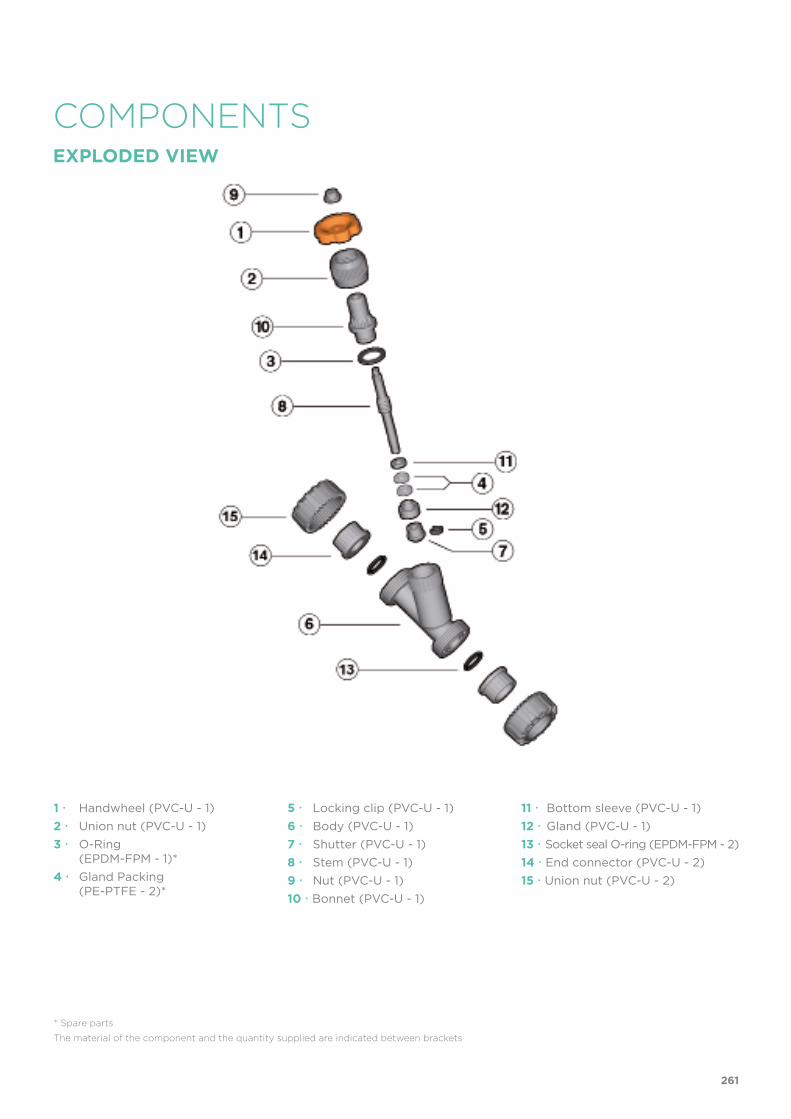
COMPONENTSEXPLODED VIEW
1 Handwheel (PVC-U - 1)2 Union nut (PVC-U - 1)3 O-Ring (EPDM-FPM - 1)*4 Gland Packing (PE-PTFE - 2)*
* Spare parts
The material of the component and the quantity supplied are indicated between brackets
5 Locking clip (PVC-U - 1)6 Body (PVC-U - 1)7 Shutter (PVC-U - 1)8 Stem (PVC-U - 1)9 Nut (PVC-U - 1)10 Bonnet (PVC-U - 1)
11 Bottom sleeve (PVC-U - 1)12 Gland (PVC-U - 1)13 Socket seal O-ring (EPDM-FPM - 2)14 End connector (PVC-U - 2)15 Union nut (PVC-U - 2)
261

DISMOUNTING MOUNTING1) Isolate the valve from the fluid flow.2) Unscrew the union nut (2)
anticlockwise and then remove the internal assembly, complete with all its components, from the body (6).
3) Remove the locking clip (5) and shutter (7).
4) Remove the gland (12).5) Unscrew the nut (9) remove the
handwheel (1) and union nut (2).6) Rotate the stem (8) clockwise
and remove it completely from the bonnet (10). At this point it is possible to access the gland packing (4), the bottom sleeve (11) and the O-Ring (3) which be easily removed.
1) Insert the stem (8) in the bonnet (10) and screw anticlockwise.
2) Insert in order: O-Ring, (3) bottom sleeve (11) and gland packing (4).
3) Place the union nut (2) on the stem, screw on the handwheel (1) and nut (9).
4) Insert the gland (12) and shutter (7) on the stem (8), insert the locking clip (5) in its housing.
5) Insert the completed assembly in the body, making sure that the locating tab on the bonnet sits in its housing in the body
6) Lock the union nut.
Note: maintenance operations can be carried out with the valve body installed. During assembly operations, it is advisable to lubricate the rubber seals. Mineral oils are not recommended for this task as they react aggressively with EPDM rubber.
INSTALLATION
WARNINGS
1) Install the valve such that the arrow stamped on the body indicates the direction of fluid flow .
2) If the valve is installed in a vertical position, if the connection is solvent welded, make sure that the solvent does not enter inside the body, as this would damage the seating of the seal.
3) Before putting the valve into service, check the tightness of the union nut (2).
- Do not used compressed air or other gases to test thermoplastic lines.- Always avoid sudden closing manoeuvres and protect the valve from accidental
manoeuvres.
262


VR DN 10÷100PVC-U
Check valve

266
Technical specificationsConstruction Angle seat check valveSize range DN 10 ÷ 100Nominal pressure DN 10÷50: PN 16 with water at 20 °C
DN 65: PN 10 with water at 20 °CDN 80÷100: PN 6 with water at 20 °C
Temperature range 0 °C ÷ 60 °CCoupling standards Solvent welding: EN ISO 1452, EN ISO 15493, BS 4346-1,
DIN 8063, NF T54-028, ASTM D 2467, JIS K 6743. Can be coupled to pipes according to EN ISO 1452, EN ISO 15493, DIN 8062, NF T54-016, ASTM D 1785, JIS K 6741
Thread: ISO 228-1, DIN 2999, ASTM D 2464, JIS B 0203
Flanging system: ISO 7005-1, EN ISO 1452, EN ISO 15493, EN 558-1 (DN 10÷50), DIN 2501, ANSI B.16.5 cl.150, JIS B 2220
Reference standards Construction criteria: EN ISO 16137, EN ISO 1452, EN ISO 15493Test methods and requirements: ISO 9393Installation criteria: DVS 2204, DVS 2221, UNI 11242
Valve material PVC-USeal material EPDM or FPM
VR
The VR is an angle seat check valve with weighted PVC piston that allows the passage of fluid in one direction only.
CHECK VALVE
• Connection system for solvent weld, threaded and flanged joints• No metal parts in contact with the fluid• Piston with counterweight able to work with high intensity fluid• Limited pressure drop. Only minimum back pressure is required for the
hermetic seal• Valve material compatibility (PVC-U) with water conveyance, drinking
water and other food substances according to current regulations • Can be maintained with the valve body installed
DN 10÷100

267
TECHNICAL DATA
-40 -20 0 20 40 60 80 100 120 140 °C
16
14
12
10
8
6
4
2
0
Wo
rkin
g p
ress
ure
Working temperature
bar
DN 10÷50
DN 65÷80
DN 100
PRESSURE VARIATION ACCORDING TO TEMPERATURE
For water and non-hazardous fluids with regard to which the material is classified as CHEMICALLY RESISTANT. In other cases, a reduction of the nominal pressure PN is required (25 years with safety factor).
PRESSURE DROP GRAPH
Pre
ssu
re d
rop
Flow Rate
bar1 10 100 1000 10000 l/min
1
0.1
0.01
0.001
DN
15
DN
10
DN
20
DN
25
DN
32
DN
40
DN
50
DN
65
DN
80
DN
100
KV100 FLOW COEFFICIENTThe Kv100 flow coefficient is the Q flow rate of litres per minute of water at a temperature of 20°C that will generate ∆p= 1 bar pressure drop at a certain valve position.The Kv100 values shown in the table are calculated with the valve completely open.
DN 10 15 20 25 32 40 50 65 80 100
Kv100 47 110 205 375 560 835 1300 1950 2600 3500

268
The information in this leaflet is provided in good faith. No liability will be accepted concerning technical data that is not directly covered by recognised international standards. FIP reserves the right to carry out any modification. Products must be installed and maintained by qualified personnel.
The figures refer to the seals that are not worn.
DN 10 15 20 25 32 40 50 65 80 100
bar 0.008 0.008 0.009 0.014 0.017 0.018 0.021 0.022 0.022 0.024
DN 10 15 20 25 32 40 50 65 80 100
mm H2O 150 150 200 350 350 350 350 350 350 350
MINIMUM SEALING PRESSURE (PISTON IN CLOSED POSITION)
MINIMUM PRESSURE REQUIRED TO LIFT THE PISTON

R DN PN A max B E H L Z Fig. g EPDM Code FPM Code
3/8” 10 16 125 72 55 135 11.4 112.2 A 221 VRUFV038E VRUFV038F
1/2” 15 16 125 72 55 143 15 113 A 230 VRUFV012E VRUFV012F
3/4” 20 16 145 84 66 160 16.3 127.4 A 390 VRUFV034E VRUFV034F
1” 25 16 165 95 75 183 19.1 144.8 A 602 VRUFV100E VRUFV100F
1”1/4 32 16 190 111 87 214 21.4 171.2 A 932 VRUFV114E VRUFV114F
1”1/2 40 16 210 120 100 235 21.4 192.2 A 1341 VRUFV112E VRUFV112F
2” 50 16 240 139 120 285 25.7 233.6 A 2348 VRUFV200E VRUFV200F
d DN PN A max B E H L Z Fig. g EPDM Code FPM Code
16 10 16 125 72 55 135 14 107 A 218 VRUIV016E VRUIV016F
20 15 16 125 72 55 135 16 103 A 226 VRUIV020E VRUIV020F
25 20 16 145 84 66 158 19 120 A 388 VRUIV025E VRUIV025F
32 25 16 165 95 75 176 22 132 A 606 VRUIV032E VRUIV032F
40 32 16 190 111 87 207 26 155 A 923 VRUIV040E VRUIV040F
50 40 16 210 120 100 243 31 181 A 1335 VRUIV050E VRUIV050F
63 50 16 240 139 120 298 38.2 221.6 A 2313 VRUIV063E VRUIV063F
d DN PN A max B E H K L Z Fig. g EPDM Code FPM Code
75 65 10 300 179 104 243 96 44 155 B 3485 VRIV075E VRIV075F
90 80 6 325 192 116 262 105 51 160 B 4530 VRIV090E VRIV090F
110 100 6 385 231 138 325 - 61 203 C 7170 VRIV110E VRIV110F
VRUIVCheck valve with female union ends for solvent welding, metric series
VRIVCheck valve with female ends for solvent welding, metric series
VRUFVCheck valve with BSP threaded female union ends
also available with standard ANSI, BS and JIS connections
also available with standard ASTM/NPT connections
269

d DN PN A max B F f H Fig. g EPDM Code FPM Code
20 15 16 125 72 65 14 130 A 280 VROV020E VROV020F
25 20 16 145 84 75 14 150 A 430 VROV025E VROV025F
32 25 16 165 95 85 14 160 A 640 VROV032E VROV032F
40 32 16 190 111 100 18 180 A 1035 VROV040E VROV040F
50 40 16 210 120 110 18 200 A 1405 VROV050E VROV050F
63 50 16 240 139 125 18 230 A 2235 VROV063E VROV063F
75 65 10 300 179 145 17 356 B 4600 VROV075E VROV075F
90 80 6 325 192 160 17 404 B 6300 VROV090E VROV090F
110 100 6 385 231 180 17 475 C 9200 VROV110E VROV110F
d DN PN A max B H L Fig. g EPDM Code FPM Code
16 10 16 125 72 114 14 A 125 VRDV016E VRDV016F
20 15 16 125 72 124 16 A 135 VRDV020E VRDV020F
25 20 16 145 84 144 19 A 225 VRDV025E VRDV025F
32 25 16 165 95 154 22 A 360 VRDV032E VRDV032F
40 32 16 190 111 174 26 A 590 VRDV040E VRDV040F
50 40 16 210 120 194 31 A 835 VRDV050E VRDV050F
63 50 16 240 139 224 38 A 1420 VRDV063E VRDV063F
R DN PN A max B E H K L Z Fig. g EPDM Code FPM Code
2”1/2 65 10 300 179 104 243 96 30.2 182.6 B 3485 VRFV212E VRFV212F
3” 80 6 325 192 116 262 105 33.3 195.4 B 4520 VRFV300E VRFV300F
4” 100 6 385 231 138 325 - 39.3 246.4 C 6965 VRFV400E VRFV400F
VRFV
VRDV
Check valve with BSP threaded female ends
Check valve with male ends for solvent welding, metric series
VROVCheck valve with fixed flanges, drilled PN10/16
270

EXPLODED VIEW
DN 15÷50 DN 65÷80 DN 100
1 Body (PVC-U - 1)2 Piston (PVC-U - 1)3 Bonnet (PVC-U - 1)4 O-Ring (EPDM-FPM - 1/2)*
* Spare parts
The material of the component and the quantity supplied are indicated between brackets
5 Piston flat gasket (EPDM-FPM - 1)*6 Union nut (PVC-U - 1)7 Retaining ring (PVC-U - 1)8 Socket seal O-Ring (EPDM-FPM - 2)*
9 End connector (PVC-U - 2)*10 Union nut (PVC-U - 2)
271

INSTALLATION
DISMOUNTING MOUNTINGDN 15÷50 - DN 100 (fig. A and C)1) Isolate the valve from the fluid flow.2) Unscrew the union nut (6) and
separate the bonnet (3) from the body (1).
3) Remove the piston (2) and flat gasket (5).
4) Remove the retaining ring (7) and separate the union nut (6) from the bonnet (3).
5) Remove the O-Ring from the bonnet (4).
DN 65÷100 (fig. B)1) Isolate the valve from the fluid flow.2) Unscrew the bonnet (3) from the
body (1).3) Remove the O-Ring (4) from its
seating in the body (1).4) Remove the piston (2) and relative
flat gasket (5).
DN 15÷50 - DN 100 (fig. A and C)1) Insert the O-Ring (4) in its seating in
the bonnet (3).2) Insert the bonnet (3) in union nut (6)
and fix the two components using the retaining ring (7).
3) Insert the piston (2) complete with flat gasket (5) in the bonnet (3), then fit the bonnet on the body (1).
4) Screw the union nut (6) on the body (1)
DN 65÷100 (fig. B)1) Insert the piston (2) complete with
flat gasket (5) in the bonnet (3).2) Insert the O-ring (4) in the body (1)
seating.3) Screw the bonnet (3) to the body (1)
Note: maintenance operations can be carried out with the valve body installed during assembly, it is advisable to lubricate the rubber seals. Mineral oils are not recommended for this task as they react aggressively with EPDM rubber.
Fig. C
Fig. B
Fig. A
WARNINGS
1) The check valve can be installed on vertical or horizontal axis pipes. The bonnet (3) must however always be turned upwards as the piston works by gravity.
2) If the valve is installed in a vertical position, if the connection is solvent welded, make sure that the solvent cement does not enter inside the body, as this would damage the seating of the seal.
3) Install the valve such that the arrow stamped on the body indicates the direction of fluid flow .
- Do not used compressed air or other gases to test thermoplastic lines.
272


VA DN 15÷50PVC-U
Air release valve

276
Technical specificationsConstruction Air release valveSize range DN 15 ÷ 50Nominal pressure PN 16 with water at 20 °CTemperature range 0 °C ÷ 60 °CCoupling standards Solvent welding: EN ISO 1452, EN ISO 15493, BS
4346-1, DIN 8063, NF T54-028.Can be coupled to pipes according to EN ISO 1452, EN ISO 15493, DIN 8062, NF T54-016Thread: ISO 228-1, DIN 2999
Reference standards Construction criteria: EN ISO 16137, EN ISO 1452, EN ISO 15493Test methods and requirements: ISO 9393Installation criteria: DVS 2204, DVS 2221, UNI 11242
Valve material PVC-USeal material EPDM
VA
The purpose of the VA air release is to eliminate any air entering the pipe with the liquid.
AIR RELEASE VALVE
• Connection system for solvent weld and threaded joints • No metal parts in contact with the fluid• Can be used as a vacuum breaker valve when installed with the nut at the
bottom • Valve material compatibility (PVC-U) with water, drinking water and other
food substance conveyance according to current regulations• Can be maintained with the valve body installed
DN 15÷50

277
TECHNICAL DATA
-40 -20 0 20 40 60 80 100 120 140 °C
16
14
12
10
8
6
4
2
0
Wo
rkin
g p
ress
ure
Working temperature
barPRESSURE VARIATION ACCORDING TO TEMPERATUREFor water and non-hazardous fluids with regard to which the material is classified as CHEMICALLY RESISTANT. In other cases, a reduction of the nominal pressure PN is required (25 years with safety factor).
The information in this leaflet is provided in good faith. No liability will be accepted concerning technical data that is not directly covered by recognised international standards. FIP reserves the right to carry out any modification. Products must be installed and maintained by qualified personnel.
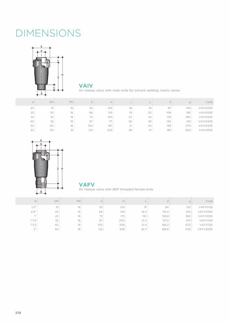
DIMENSIONS
d DN PN E H L L1 Z g Code
20 15 16 55 103 16 18 87 105 VAIV020E
25 20 16 66 125 19 20 106 185 VAIV025E
32 25 16 75 150 22 24 128 280 VAIV032E
40 32 16 87 171 26 28 145 415 VAIV040E
50 40 16 100 187 31 34 156 570 VAIV050E
63 50 16 122 223 38 41 185 950 VAIV063E
R DN PN E H L Z g Code
1/2” 15 16 55 124 15 94 120 VAFV012E
3/4” 20 16 66 149 16.3 116.4 205 VAFV034E
1” 25 16 75 175 19.1 136.8 360 VAFV100E
1”1/4 32 16 87 200 21.4 157.2 475 VAFV114E
1”1/2 40 16 100 209 21.4 166.2 670 VAFV112E
2” 50 16 122 248 25.7 196.6 1130 VAFV200E
VAIVAir release valve with male ends for solvent welding, metric series
VAFVAir release valve with BSP threaded female ends
278

COMPONENTSEXPLODED VIEW
1 Body (PVC-U - 1)2 Piston (PVC-U - 1)3 End connector (PVC-U - 1)
* Spare parts
The material of the component and the quantity supplied are indicated between brackets
4 Union nut (PVC-U - 1)5 O-Ring (EPDM - 1)*
6 Piston gasket (EPDM - 1)*
279

DISMOUNTING MOUNTING1) Isolate the valve from the fluid and
empty the entire line upstream.2) Unscrew the union nut (4).3) Remove the end connector (3) and
O-ring (5).4) Remove the piston (2) and relative
seal (6).
1) Position the O-ring (5) and piston gasket (6) in their seatings.
2) Insert the piston (2) in the body (1).3) Position the end connector (3).4) Tighten the union nut (4).
Note: during assembly operations, it is advisable to lubricate the rubber seals. Mineral oils are not recommended for this task as they react aggressively with EPDM rubber.
Fig. 1INSTALLATIONThe FIP air release valve must always be installed in a vertical position with the union nut at the top, as shown in fig.1.
280


VZ DN 10÷50PVC-U
Foot valve

284
Technical specificationsConstruction Foot valveSize range DN 10 ÷ 50Nominal pressure PN 16 with water at 20 °CTemperature range 0 °C ÷ 60 °CCoupling standards Solvent welding: EN ISO 1452, EN ISO 15493, BS
4346-1, DIN 8063, NF T54-028. Can be coupled to pipes according to EN ISO 1452, EN ISO 15493, DIN 8062, NF T54-016Thread: ISO 228-1, DIN 2999
Reference standards Construction criteria: EN ISO 16137, EN ISO 1452, EN ISO 15493Test methods and requirements: ISO 9393Installation criteria: DVS 2204, DVS 2221, UNI 11242
Valve material PVC-USeal material EPDM
VZ
The VZ foot valve allows the passage of fluid in one direction only.
FOOT VALVE
• Connection system for solvent weld and threaded joints • No metal parts in contact with the fluid• Piston with incorporated counterweight able to work with high intensity
fluid• Limited pressure loss. Only minimum back pressure is required for the
hermetic seal• Valve material compatibility (PVC-U) with water, drinking water and other
food substance conveyance according to current regulations • Can be maintained with the valve body installed
DN 10÷50

285
TECHNICAL DATA
-40 -20 0 20 40 60 80 100 120 140 °C
16
14
12
10
8
6
4
2
0
Wo
rkin
g p
ress
ure
Working temperature
barPRESSURE VARIATION ACCORDING TO TEMPERATUREFor water and non-hazardous fluids with regard to which the material is classified as CHEMICALLY RESISTANT. In other cases, a reduction of the nominal pressure PN is required. (25 years with safety factor)
The information in this leaflet is provided in good faith. No liability will be accepted concerning technical data that is not directly covered by recognised international standards. FIP reserves the right to carry out any modification. Products must be installed and maintained by qualified personnel.
The figures refer to the seals that are not worn.
DN 10 15 20 25 32 40 50
bar 0.008 0.008 0.009 0.014 0.017 0.018 0.021
DN 10 15 20 25 32 40 50
mm H2O 150 150 200 350 350 350 350
MINIMUM SEALING PRESSURE (PISTON IN CLOSED POSITION)
MINIMUM PRESSURE REQUIRED TO LIFT THE PISTON
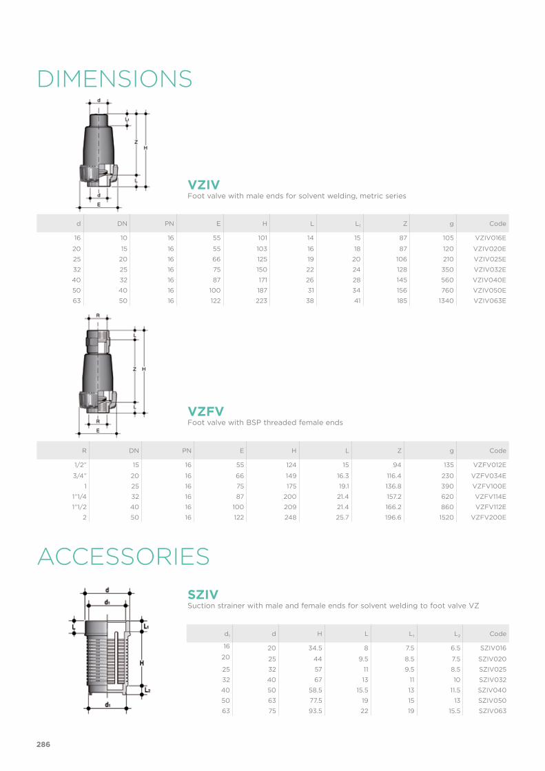
DIMENSIONS
ACCESSORIES
d DN PN E H L L1 Z g Code
16 10 16 55 101 14 15 87 105 VZIV016E
20 15 16 55 103 16 18 87 120 VZIV020E
25 20 16 66 125 19 20 106 210 VZIV025E
32 25 16 75 150 22 24 128 350 VZIV032E
40 32 16 87 171 26 28 145 560 VZIV040E
50 40 16 100 187 31 34 156 760 VZIV050E
63 50 16 122 223 38 41 185 1340 VZIV063E
R DN PN E H L Z g Code
1/2” 15 16 55 124 15 94 135 VZFV012E
3/4” 20 16 66 149 16.3 116.4 230 VZFV034E
1 25 16 75 175 19.1 136.8 390 VZFV100E
1”1/4 32 16 87 200 21.4 157.2 620 VZFV114E
1”1/2 40 16 100 209 21.4 166.2 860 VZFV112E
2 50 16 122 248 25.7 196.6 1520 VZFV200E
d1 d H L L1 L2 Code
16 20 34.5 8 7.5 6.5 SZIV01620 25 44 9.5 8.5 7.5 SZIV020
25 32 57 11 9.5 8.5 SZIV025
32 40 67 13 11 10 SZIV032
40 50 58.5 15.5 13 11.5 SZIV040
50 63 77.5 19 15 13 SZIV050
63 75 93.5 22 19 15.5 SZIV063
VZIVFoot valve with male ends for solvent welding, metric series
VZFV
SZIV
Foot valve with BSP threaded female ends
Suction strainer with male and female ends for solvent welding to foot valve VZ
286
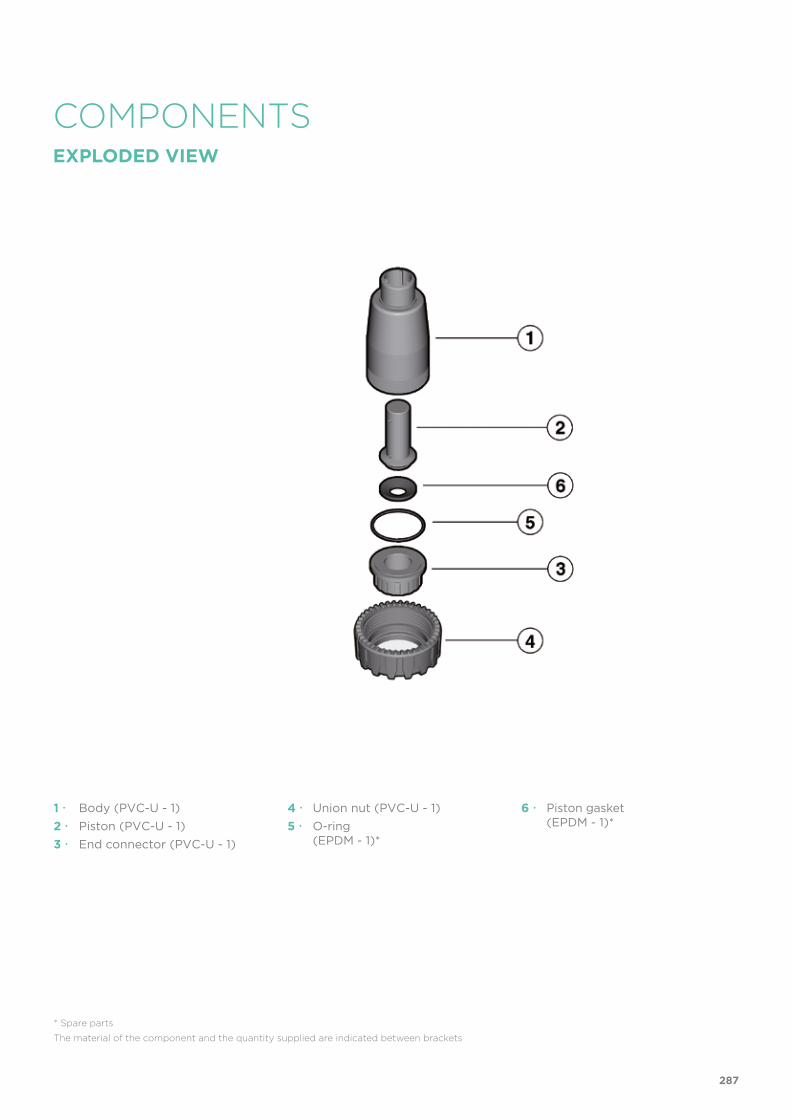
COMPONENTSEXPLODED VIEW
1 Body (PVC-U - 1)2 Piston (PVC-U - 1)3 End connector (PVC-U - 1)
* Spare parts
The material of the component and the quantity supplied are indicated between brackets
4 Union nut (PVC-U - 1)5 O-ring (EPDM - 1)*
6 Piston gasket (EPDM - 1)*
287

H1
HH1
DISMOUNTING MOUNTING1) Isolate the valve from the fluid and
empty the entire line upstream.2) Unscrew the union nut (4).3) Remove the end connector (3) and
O-ring (5).4) Remove the piston (2) and relative
gasket (6).
1) Position the O-ring (5) and piston gasket (6) in their seatings.
2) Insert the piston (2) in the body (1).3) Position the end connector (3).4) Tighten the union nut (4).
Note: during assembly operations, it is advisable to lubricate the rubber seals. Mineral oils are not recommended for this task as they react aggressively with EPDM rubber.
Fig. 1INSTALLATIONThe FIP foot valve must always be installed in a vertical position with the union nut at the bottom, as shown in fig.1.
288


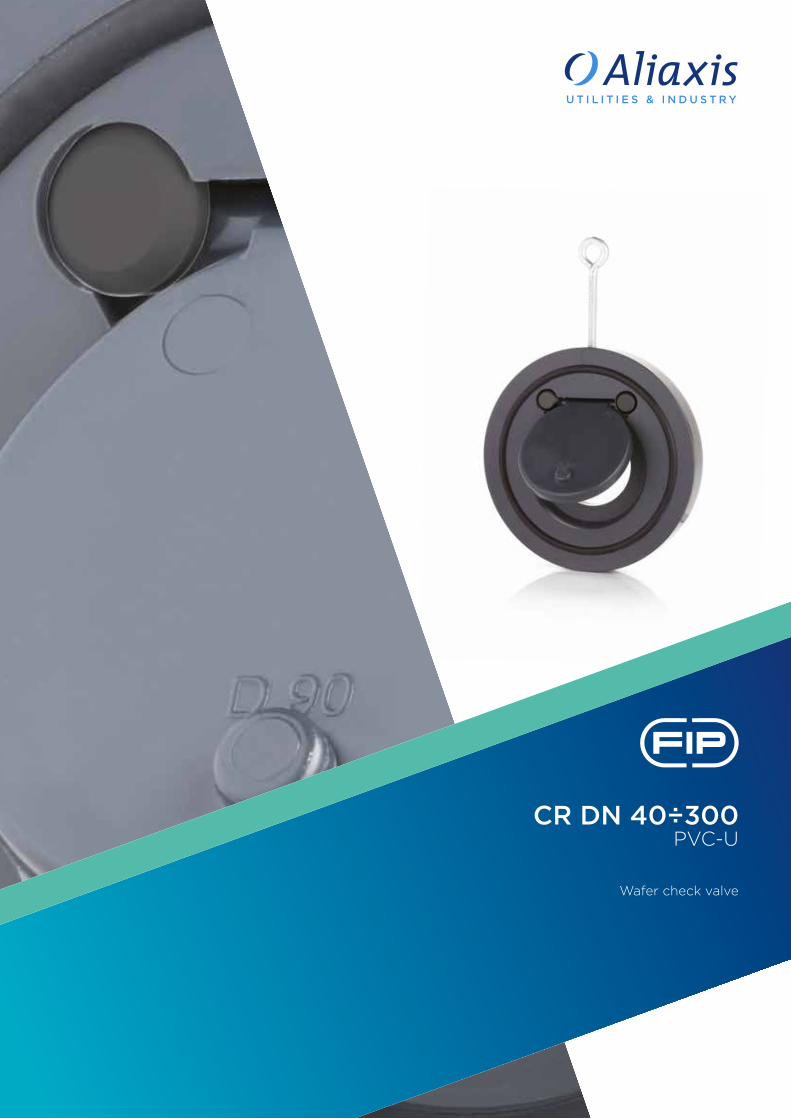
CR DN 40÷300PVC-U
Wafer check valve

292
Technical specificationsConstruction Wafer check valve Size range DN 40 ÷ 300Nominal pressure 5 bar with water at 20 °CTemperature range 0 °C ÷ 60 °CCoupling standards Flanging system: DIN 2501 PN 10, EN ISO 1452,
EN ISO 15493
Reference standards Construction criteria: EN ISO 16137, EN ISO 1452, EN ISO 15493Test methods and requirements: ISO 9393Installation criteria: DVS 2204, DVS 2221, UNI 11242
Valve material PVC-USeal material EPDM
CR
The CR wafer check valve is designed to be installed directly between stubs and flanges in accordance with ISO/DIN standards.
WAFER CHECK VALVE
• Installed with FIP QPV (d50 - d160) stubs and QRV stubs using flat gasket QHV/Y (d225 - d315), on PVC piping class PN10 or lower with type ODV flanges
• Metal support for easy and precise centring of the valve during installation
• Can be installed in either a vertical or horizontal position• Sealing system with O-ring for optimum sealing and installation without flat
gaskets
DN 40÷300

293
TECHNICAL DATA
-40 -20 0 20 40 60 80 100 120 140 °C
16
14
12
10
8
6
4
2
0
Wo
rkin
g p
ress
ure
Working temperature
barPRESSURE VARIATION ACCORDING TO TEMPERATUREFor water and non-hazardous fluids with regard to which the material is classified as CHEMICALLY RESISTANT. In other cases, a reduction of the nominal pressure PN is required (25 years with safety factor).
PRESSURE DROP GRAPH
KV100 FLOW COEFFICIENTThe Kv100 flow coefficient is the Q flow of litres per minute of water at a temperature of 20°C that will generate ∆p= 1 bar pressure drop at a certain valve position.The Kv100 values shown in the table are calculated with the valve completely open.
DN 40 50 65 80 100 125 150 200 250 300
Kv100 l/min 370 900 1250 1867 2867 5700 8167 18800 25000 31900
Pre
ssu
re d
rop
Flow Rate
bar10 100 1000 10000 100000 l/min
1
0.1
0.01
0.001
DN
50
DN
40
DN
65
DN
80
DN
100
DN
125
DN
150
DN
20
0D
N 2
50D
N 3
00

294
The information in this leaflet is provided in good faith. No liability will be accepted concerning technical data that is not directly covered by recognised international standards. FIP reserves the right to carry out any modification. Products must be installed and maintained by qualified personnel.
MINIMUM PRESSURE REQUIRED TO OPEN THE VALVE IN A VERTICAL FLOW
MINIMUM VALVE SEALING PRESSURES
TIGHTENING TORQUE *Tightening torques for nuts and bolts on couplings with backing rings. Values required to obtain the hydraulic test seal (1.5 x PN at 20°C) (new or lubricated nuts and bolts)
DN 40 50 65 80 100 125 150 200 250 300
bar 0.002 0.003 0.003 0.003 0.003 0.003 0.005 0.005 0.008 0.008
DN 40 50 65 80 100 125 150 200 250 300
bar 0.3 0.3 0.3 0.2 0.2 0.2 0.2 0.2 0.2 0.2
DN 40 50 65 80 100 125 150 200 250 300
Nm* 8 10 10 10 10 15 20 38 45 50
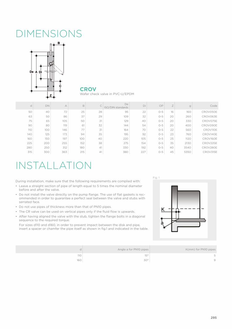
INSTALLATION
DIMENSIONS
d DN A B C DeISO/DIN standards Di OP Z g Code
50 40 72 25 28 95 22 0-5 16 160 CROV050E
63 50 86 37 29 109 32 0-5 20 260 CROV063E
75 65 105 50 31 129 40 0-5 20 330 CROV075E
90 80 119 61 32 144 54 0-5 20 400 CROV090E
110 100 146 77 31 164 70 0-5 22 560 CROV110E
140 125 173 94 35 195 92 0-5 23 760 CROV140E
160 150 197 100 40 220 105 0-5 25 1120 CROV160E
225 200 255 152 38 275 154 0-5 35 2130 CROV225E
280 250 312 180 41 330 192 0-5 40 3540 CROV280E
315 300 363 215 41 380 227 0-5 45 5350 CROV315E
d Angle a for PN10 pipes K(mm) for PN10 pipes
110 15° 5
160 30° 9
CROVWafer check valve in PVC-U/EPDM
Fig. 1During installation, make sure that the following requirements are complied with:• Leave a straight section of pipe of length equal to 5 times the nominal diameter
before and after the valve.• Do not install the valve directly on the pump flange. The use of flat gaskets is rec-
ommended in order to guarantee a perfect seal between the valve and stubs with serrated face.
• Do not use pipes of thickness more than that of PN10 pipes.• The CR valve can be used on vertical pipes only if the fluid flow is upwards.• After having aligned the valve with the stub, tighten the flange bolts in a diagonal
sequence to the required torque. For sizes d110 and d160, in order to prevent impact between the disk and pipe,
insert a spacer or chamfer the pipe itself as shown in fig.1 and indicated in the table.
295


ABS acrylonitrile butadiene styrene
d nominal external diameter of the pipe in mm
DN nominal internal diameter of the pipe in mm
EPDM Ethylene-Propylene-Diene-Monomer
FPM (FKM) fluoroelastomer
g weight in grams
HIPVC PVC high impact
K lid key
NBR nitrile butadiene rubber
OP operating pressure
P pipe holder
PA-GR fibreglass reinforced polyamide
PBT polybutylene terephthalate
PE polyethylene
PN nominal pressure in bar (max. operating pressure at 20°C water)
POM polyoxymethylene
PP-GR fibreglass reinforced polypropylene
PP-H polypropylene homopolymer
PVC-C chlorinated polyvinyl chloride
PVC-U unplasticized polyvinylchloride
PVDF polyvinylidene difluoride
PTFE polyethrafluorethylene
R nominal thread size in inches
s pipe thickness in mm
SDR standard dimension ratio = d/s
U number of holes
KEYABBREVIATIONS
297