Manual, Utility Coupler, GKx Document #9620-20-B … · Manual, Utility Coupler, GKx. Document...
67
Manual, Utility Coupler, GKx Document #9620-20-B-GKx Utility Coupler-06 Pinnacle Park • 1031 Goodworth Drive • Apex, NC 27539 • Tel: 919.772.0115 • Fax: 919.772.8259 • www.ati-ia.com • Email: [email protected] B-1 Table of Contents B. Base Utility Coupler ................................................................................................................B-3 GKx Series—Compliant Utility Coupler......................................................................................B-3 1. Product Overview ..................................................................................................................B-3 1.1 9123-GKx Compliant Utility Coupler Master ........................................................................... B-5 1.2 9123-GKx Compliant Utility Coupler Tool ............................................................................... B-6 1.3 9123-GK1 Master Plate Assembly ............................................................................................ B-7 1.4 9123-GK1 Tool Plate Assembly ................................................................................................ B-7 1.5 9123-GK2 Master Plate Assembly ............................................................................................ B-8 1.6 9123-GK2 Tool Plate Assembly ................................................................................................ B-9 2. Installation ...........................................................................................................................B-10 2.1 Utility Coupler Master Installation ......................................................................................... B-10 2.2 Utility Coupler Master Removal ..............................................................................................B-11 2.3 Utility Coupler Tool Assembly Installation.............................................................................B-11 2.4 Utility Coupler Tool Assembly Removal................................................................................ B-12 2.5 Electrical Connections............................................................................................................ B-12 2.6 Pneumatic Guided Cylinder Assemblies............................................................................... B-13 2.7 Electric Drive Actuator Sensor Setting Procedure............................................................... B-13 2.7.1 Electric Drive Actuator Sensor Adjustment ....................................................................B-13 3. Operation .............................................................................................................................B-14 3.1 Coupling ................................................................................................................................... B-14 3.2 Guided Cylinder or Drive Unit Dependency.......................................................................... B-14 3.3 Uncoupling............................................................................................................................... B-14 4. Maintenance.........................................................................................................................B-15 4.1 Preventive Maintenance ......................................................................................................... B-15 4.2 Clean, Inspect, and Lubricate Thrust Bearings for Utility Couplers .................................. B-16 4.3 Pin Block Inspection and Cleaning ....................................................................................... B-17 4.4 Clear Dust and Debris from Compliance Springs Area ....................................................... B-18 5. Troubleshooting and Service Procedures ........................................................................B-19 5.1 Troubleshooting Procedures ................................................................................................. B-19 5.2 Service Procedures ................................................................................................................. B-21 5.2.1 Clean, Inspect, Lubricate, Replace Components for Master Check Port ......................B-21 5.2.2 Clean, Inspect, Lubricate, Replace Components for Tool Check Port ..........................B-23 5.2.3 V-ring Seal Replacement...............................................................................................B-25 5.2.4 Tool Presence Sensor Replacement for GK Units ........................................................B-26 5.2.5 GK1CM Thrust Bearing, Chamfered Washer, and Shoulder Bolt Replacement ...........B-27
-
Upload
nguyendang -
Category
Documents
-
view
237 -
download
1
Transcript of Manual, Utility Coupler, GKx Document #9620-20-B … · Manual, Utility Coupler, GKx. Document...

Manual, Utility Coupler, GKxDocument #9620-20-B-GKx Utility Coupler-06
Pinnacle Park • 1031 Goodworth Drive • Apex, NC 27539 • Tel: 919.772.0115 • Fax: 919.772.8259 • www.ati-ia.com • Email: [email protected] B-1
Table of ContentsB. Base Utility Coupler ................................................................................................................B-3GKx Series—Compliant Utility Coupler ......................................................................................B-31. Product Overview ..................................................................................................................B-3
1.1 9123-GKx Compliant Utility Coupler Master ........................................................................... B-5
1.2 9123-GKx Compliant Utility Coupler Tool ............................................................................... B-6
1.3 9123-GK1 Master Plate Assembly ............................................................................................ B-7
1.4 9123-GK1 Tool Plate Assembly ................................................................................................ B-7
1.5 9123-GK2 Master Plate Assembly ............................................................................................ B-8
1.6 9123-GK2 Tool Plate Assembly ................................................................................................ B-9
2. Installation ...........................................................................................................................B-102.1 Utility Coupler Master Installation ......................................................................................... B-10
2.2 Utility Coupler Master Removal ..............................................................................................B-11
2.3 Utility Coupler Tool Assembly Installation .............................................................................B-11
2.4 Utility Coupler Tool Assembly Removal ................................................................................ B-12
2.5 Electrical Connections ............................................................................................................ B-12
2.6 Pneumatic Guided Cylinder Assemblies............................................................................... B-13
2.7 Electric Drive Actuator Sensor Setting Procedure............................................................... B-132.7.1 Electric Drive Actuator Sensor Adjustment ....................................................................B-13
3. Operation .............................................................................................................................B-143.1 Coupling ................................................................................................................................... B-14
3.2 Guided Cylinder or Drive Unit Dependency .......................................................................... B-14
3.3 Uncoupling ............................................................................................................................... B-14
4. Maintenance .........................................................................................................................B-154.1 Preventive Maintenance ......................................................................................................... B-15
4.2 Clean, Inspect, and Lubricate Thrust Bearings for Utility Couplers .................................. B-16
4.3 Pin Block Inspection and Cleaning ....................................................................................... B-17
4.4 Clear Dust and Debris from Compliance Springs Area ....................................................... B-18
5. Troubleshooting and Service Procedures ........................................................................B-195.1 Troubleshooting Procedures ................................................................................................. B-19
5.2 Service Procedures ................................................................................................................. B-215.2.1 Clean, Inspect, Lubricate, Replace Components for Master Check Port ......................B-21
5.2.2 Clean, Inspect, Lubricate, Replace Components for Tool Check Port ..........................B-23
5.2.3 V-ring Seal Replacement ...............................................................................................B-25
5.2.4 Tool Presence Sensor Replacement for GK Units ........................................................B-26
5.2.5 GK1CM Thrust Bearing, Chamfered Washer, and Shoulder Bolt Replacement ...........B-27

Manual, Utility Coupler, GKxDocument #9620-20-B-GKx Utility Coupler-06
Pinnacle Park • 1031 Goodworth Drive • Apex, NC 27539 • Tel: 919.772.0115 • Fax: 919.772.8259 • www.ati-ia.com • Email: [email protected] B-2
5.2.6 GK2CM Thrust Bearing, Chamfered Washer, and Shoulder Bolt Replacement ...........B-28
5.2.7 GK1CM Compliance Spring Replacement for Utility Coupler (Preferred Method) ........B-30
5.2.8 GK1CM Compliance Spring Replacement for Utility Coupler (Alternate Method) .........B-31
5.2.9 GK2CM Compliance Spring Replacement for Utility Coupler (Preferred Method) ........B-32
5.2.10 GK2CM Compliance Spring Replacement for Utility Coupler (Alternate Method) .........B-33
5.2.11 Center Swivel Replacement for Utility Coupler .............................................................B-34
5.2.12 GK1CM Alignment Pin Replacement ...........................................................................B-35
5.2.13 GK2CM Alignment Pin Replacement ............................................................................B-36
5.2.14 GK-GC-B63S50Z1 Return Spring Replacement ...........................................................B-38
5.2.15 GK-GC-B63S50Z1ExhaustMufflerReplacement ........................................................B-39
6. Serviceable Parts ................................................................................................................B-406.1 GK1 Compliant Utility Coupler Master (9123-GK1CM-0-0-0-0) ............................................ B-40
6.2 GK2 Compliant Utility Coupler Master (9123-GK2CM-0-00-0-00-N/E/R) ............................. B-41
6.3 GK1 Compliant Utility Coupler Tool 9123-GK1T-0-0-0-0 ...................................................... B-43
6.4 GK2 Compliant Utility Coupler Tool 9123-GK2T-0-00-0-00-N/E/R ....................................... B-43
6.5 Models 9123-GK-GC-B63S50Z1-SG-N ................................................................................... B-44
6.6 Models 9123-GK-GC-B50S75-SG-N, 9123-GK-GC-B63S75-SG-N ........................................ B-45
6.7 Models 9123-GK-GCE-PM24400-B-SG, 9123-GK-GCE2-PM24600-B-SG ............................ B-45
7. Specifications ......................................................................................................................B-468. Drawings ..............................................................................................................................B-48
8.1 GK1 Compliant Utility Coupler Drawings .............................................................................. B-48
8.2 GK2-N Compliant Utility Coupler Drawings .......................................................................... B-51
8.3 GK2-E Compliant Utility Coupler Drawings .......................................................................... B-54
8.4 GK2-R Compliant Utility Coupler Drawings .......................................................................... B-57
8.5 GK-GC-B50S75-SG-N .............................................................................................................. B-60
8.6 GK-GC-B63S50Z1-SG-N .......................................................................................................... B-61
8.7 GK-GC-B63S75-SG-N .............................................................................................................. B-63
8.8 GK-GCE2-PM24600-B-SG ....................................................................................................... B-64
8.9 GK-GCE-PM24400-B-SG ......................................................................................................... B-66

Manual, Utility Coupler, GKxDocument #9620-20-B-GKx Utility Coupler-06
Pinnacle Park • 1031 Goodworth Drive • Apex, NC 27539 • Tel: 919.772.0115 • Fax: 919.772.8259 • www.ati-ia.com • Email: [email protected] B-3
B. Base Utility Coupler
GKx Series—Compliant Utility Coupler1. Product Overview
The GKx Compliant Utility Coupler is designed for medium-duty industrial applications. The Utility Coupler provides pass through utilities such as air, fluids, and electrical signals from both integrated ports within the body and standard ATI add-on standard rectangular mounted modules. Consult ATI for further details.
This document provides information on the GKx series Utility Couplers listed in Table 1.1.
The Utility Couplers are comprised of a compliant Master side and Tool side. The Master side is equipped with a compliance mechanism that allows for large tooling misalignments. The Utility Coupler depends on force from the guided cylinder assembly to maintain constant coupling pressure. The recommended operating pressure for the guided cylinder is 80 psi (5.52 bar). The unit will work in operating pressures between 60 – 120 psi (4.14 – 8.27 bar).
Figure 1.1—GKx Compliant Utility Coupler with Guided Cylinder Assembly
Guided Drive Cylinder (9123-GK-GC-B50S75-SG-N Shown)
Compliant Utility Coupler Master Side(9123-GK2CM Shown)
Compliant Utility Coupler Tool Side(9123-GK2T Shown)

Manual, Utility Coupler, GKxDocument #9620-20-B-GKx Utility Coupler-06
Pinnacle Park • 1031 Goodworth Drive • Apex, NC 27539 • Tel: 919.772.0115 • Fax: 919.772.8259 • www.ati-ia.com • Email: [email protected] B-4
Some Utility Coupler Master models feature integrated check ports that pass utilities on to the Tool side. Master and Tool bodies are equipped with a standard rectangular mounting feature that enables the coupler to accept up to (4) additional 9120 series Tool Changer utility modules for pass-through air, fluids, and electrical signals. Consult ATI for further details.
Table 1.1—GKx Series Utility Coupler Models
Base AssemblyPart Number Description Configuration
Part Number
Sensors for Tool
PresenceAir Ports
9123-GK1CM-0-0-0-0
GK1 Compliant Utility Coupler Master Base Assembly
9123-GK1CM-0-0-0-0-SE (2) NPN N/A
9123-GK1CM-0-0-0-0-SG (2) PNP N/A
9123-GK1T-0-0-0-0GK1 Utility Coupler Tool Base Assembly
N/A N/A N/A
9123-GK2CM-0-00-0-00-N
GK2 Compliant Utility Coupler Master Base Assembly
9123-GK2CM-0-00-0-00-SE-N (2) NPN (2) 3/8 NPT Checked Ports
9123-GK2CM-0-00-0-00-SG-N (2) PNP (2) 3/8 NPT Checked Ports
9123-GK2CM-0-00-0-00-E
9123-GK2CM-0-00-0-00-SE-E (2) NPN (2) 3/8” BSPP Checked Ports
9123-GK2CM-0-00-0-00-SG-E (2) PNP (2) 3/8” BSPP Checked Ports
9123-GK2CM-0-00-0-00-R9123-GK2CM-0-00-0-00-SE-R (2) NPN (2) 3/8” BSPT
Checked Ports
9123-GK2CM-0-00-0-00-SG-R (2) PNP (2) 3/8” BSPT Checked Ports
9123-GK2T-0-00-0-00-NGK2 Utility Coupler Tool Base Assembly
N/A N/A
(2) 3/8 NPT Checked Ports
9123-GK2T-0-00-0-00-E (2) G 3/8 BSPP Checked Ports
9123-GK2T-0-00-0-00-R (2) Rc 3/8 BSPT Checked Ports

Manual, Utility Coupler, GKxDocument #9620-20-B-GKx Utility Coupler-06
Pinnacle Park • 1031 Goodworth Drive • Apex, NC 27539 • Tel: 919.772.0115 • Fax: 919.772.8259 • www.ati-ia.com • Email: [email protected] B-5
1.1 9123-GKx Compliant Utility Coupler MasterThe Master housing assembly includes an anodized aluminum body, (2) hardened stainless-steel alignment pins, proximity sensors, and hardened steel overload pins to limit compliance. There are preloaded springs internal to the housing that forces the main body to self-center on custom chamfered thrust bearings, which allows for 4 mm compliance in any direction in the coupling plane and for ± 3 degrees angular compliance. This system allows for a relatively large misalignment of the Master and Tool prior to coupling.
Figure 1.2—GK1 Compliant Utility Coupler Master Assembly
(3) Compliance Overload Pins with Custom Self-Centering Thrust Bearings
(2) Hardened StainlessSteel Alignment Pins
Compliant Interface Mounting Plate
(3) Preloaded SpringsProvide Centering Reliability
Center Swivel Bearing
(2) Tool Presence Sensors
AnodizedAluminum Body
Standard Rectangular Mounting Featurefor ATI Add-on Utility Modules
Figure 1.3—GK2 Compliant Utility Coupler Master Assembly
(2) Compliance Overload Pins with Custom Self-Centering Thrust Bearings (2) Hardened Stainless
Steel Alignment Pins
Compliant Interface Mounting Plate(2) Pairs of Preloaded Springs
Provide Centering Reliability Center Swivel Bearing
Built in PassThrough Utilities
AnodizedAluminum Body
Standard Rectangular Mounting Feature for ATI Add-on Utility Modules
(2) Tool Presence Sensors

Manual, Utility Coupler, GKxDocument #9620-20-B-GKx Utility Coupler-06
Pinnacle Park • 1031 Goodworth Drive • Apex, NC 27539 • Tel: 919.772.0115 • Fax: 919.772.8259 • www.ati-ia.com • Email: [email protected] B-6
1.2 9123-GKx Compliant Utility Coupler ToolThe Tool housing assembly includes an anodized aluminum body and hardened steel alignment bushings. The Tool body is equipped with steel targets that the proximity sensors in the Master body can use to sense Tool presence.Some Utility Coupler models have integrated check ports with NPT, BSPP, or BSPT air pneumatic connections. The Tool body has flats with rectangular mounting features that enable the coupler to accept additional 9120 series Tool Changer utility modules for pass through utilities such as air, fluids, and electrical signals. Consult ATI for further details.
Figure 1.4—GK1 Compliant Utility Coupler Tool Assembly
(2) Proximinty Sensor Targets
(2) Alignment Bushings
Rectangular Mounting Feature Flat
Anodized Aluminum Body
Figure 1.5—GK2 Compliant Utility Coupler Tool Assembly
(2) 3/8 NPT Ports (9123-GK2-N)(2) G 3/8 BSPP Ports (9123-GK2-E) (2) Integrated Pass
Through Checked Ports
(2) Alignment BushingsRectangular Mounting Feature Flat
(2) Proximity sensor Targets
(2) Rc 3/8 BSPT Ports (9123-GK2-R)

Manual, Utility Coupler, GKxDocument #9620-20-B-GKx Utility Coupler-06
Pinnacle Park • 1031 Goodworth Drive • Apex, NC 27539 • Tel: 919.772.0115 • Fax: 919.772.8259 • www.ati-ia.com • Email: [email protected] B-7
1.3 9123-GK1 Master Plate AssemblyThe GK1 Master plate assembly is equipped with (2) short hardened steel alignment pins. The Master body has no integrated check port but provides (4) flats with rectangular mounting features for pass-through utilities such as air, fluids, and electrical signals. There are (3) preloaded springs internal to the housing that force the main body to self-center on custom chamfered thrust bearings. The access to the preloaded springs is from the back of the interface mounting plate. The compliance is limited by (3) overload pins. The interface mounting plate is equipped with a rectangular mounting pattern to accommodate (4) M6 socket head cap screws and has 4 mm dowel pins which can be used for alignment with the drive cylinder. The Master body has (2) proximity sensors to detect Tool presence.
Figure 1.6—GK1 Master Plate Assembly
(2) Short Alignment Pins
Rectangular Mounting Feature Flat A
Rectangular Mounting Feature Flat B
Rectangular Mounting Feature Flat C
Rectangular Mounting Feature Flat D
9123-GK1CM Compliant Utility Coupler
(2) Tool Presence Sensors
Compliant Interface Mounting Plate
(3) Compliance Overload Pins withCustom Self-Centering Thrust Bearings
Rectangular Mounting Pattern
1.4 9123-GK1 Tool Plate AssemblyThe GK1 Tool plate assembly is equipped with (2) hardened steel alignment bushings. The Tool body has no integrated check port but provides (4) flats with rectangular mounting features for pass-through utilities such as air, fluids, and electrical signals. The Tool body is equipped with a square mounting pattern to accommodate (4) M6 socket head cap screws and (2) dowel holes which can be used for alignment with the Tool. The Tool body is equipped with (2) steel targets that the proximity sensors in the Master body can use to sense Tool presence.
Figure 1.7—GK1 Tool Plate Assembly
(2) Alignment Bushings
Rectangular Mounting Feature Flat A
Rectangular Mounting Feature Flat D
Rectangular Mounting Feature Flat B
Rectangular Mounting Feature Flat C
(2) Proximinty Sensor Targets
9123-GK1T Utility Coupler Tool
Square Mounting Pattern

Manual, Utility Coupler, GKxDocument #9620-20-B-GKx Utility Coupler-06
Pinnacle Park • 1031 Goodworth Drive • Apex, NC 27539 • Tel: 919.772.0115 • Fax: 919.772.8259 • www.ati-ia.com • Email: [email protected] B-8
1.5 9123-GK2 Master Plate AssemblyThe GK2 Master plate assembly is equipped with (2) standard hardened steel alignment pins. The Master body has (2) integrated check port and provides (4) flats with rectangular mounting features for pass through utilities such as air, fluids, and electrical signals. The 9123-GK2-N model has 3/8 NPT air ports, the 9123-GK2-E model has G 3/8 BSPP air ports, and the 9123-GK-2-R model has Rc 3/8 BSPT air ports that provide the pneumatic connection for the check ports. There are (2) pairs of preloaded springs internal to the housing that force the main body to self-center on custom chamfered thrust bearings. The access to the preloaded springs is from the front of the Master plate assembly. The compliance is limited by (2) overload pins. The interface mounting plate is equipped with a rectangular mounting pattern to accommodate (4) M6 socket head cap screws and has 4 mm dowel pins which can be used for alignment with the drive cylinder. The Master body has (2) proximity sensors to detect Tool presence.
Figure 1.8—GK2 Master Plate Assembly
Rectangular Mounting Feature Flat A
Rectangular Mounting Feature Flat C
(2) Integrated Pass-ThroughCheck Ports
(2) 3/8 NPT Ports (9123-GK2-N) (2) G 3/8 BSPP Ports (9123-GK2-E)
(2) Standard Alignment Pins
Rectangular Mounting Feature Flat B (2) Positions B1 and B2
Rectangular Mounting Feature Flat D(2) position D1 and D2
(2) Tool Presence Sensors
Compliant Interface Mounting Plate
Rectangular Mounting Pattern
(2) Pairs of Preloaded Springs
(2) Compliance Overload Pins withCustom Self-Centering Thrust Bearings
(2) Rc 3/8 BSPT Ports (9123-GK2-R)

Manual, Utility Coupler, GKxDocument #9620-20-B-GKx Utility Coupler-06
Pinnacle Park • 1031 Goodworth Drive • Apex, NC 27539 • Tel: 919.772.0115 • Fax: 919.772.8259 • www.ati-ia.com • Email: [email protected] B-9
1.6 9123-GK2 Tool Plate AssemblyThe GK2 Tool plate assembly is equipped with (2) hardened steel alignment bushings. The Tool body has (2) integrated check ports and provides (4) flats with rectangular mounting features for pass-through utilities such as air, fluids, and electrical signals. The Tool body is equipped with a square mounting pattern to accommodate (4) M6 socket head cap screws and (2) dowel holes which can be used for alignment with the Tool. The Tool body is equipped with (2) steel targets that the proximity sensors in the Master body can use to sense Tool presence.
Figure 1.9—GK2 Tool Plate Assembly
(2) 3/8 NPT Ports (9123-GK2-N)(2) G 3/8 BSPP Ports (9123-GK2-E)
Rectangular Mounting Feature Flat ARectangular Mounting Feature Flat C
Rectangular Mounting Feature Flat D(2) Positions D1 and D2
Rectangular Mounting Feature Flat B(2) Positions B1 and B2
(2) Alignment Bushings(2) Proximity Sensor Targets
Square Mounting Pattern
9123-GK2TUtility Coupler Tool
(2) Integrated Pass-Through Check Ports
(2) Rc 3/8 BSPT Ports (9123-GK2-R)

Manual, Utility Coupler, GKxDocument #9620-20-B-GKx Utility Coupler-06
Pinnacle Park • 1031 Goodworth Drive • Apex, NC 27539 • Tel: 919.772.0115 • Fax: 919.772.8259 • www.ati-ia.com • Email: [email protected] B-10
2. InstallationThe Master unit is designed to attach to any compatible drive unit assembly or can be directly mounted to customer geometry. The GKx Utility Coupler and add-on modules are typically installed by ATI prior to shipment. The following steps outline the field installation or removal of the system components. The Compliant Utility Coupler Master assembly is attached to the Guided Drive Cylinder. The Master housing has a rectangular mounting pattern to accommodate (4) M6 socket head cap screws. The Master assembly also comes with 4 mm dowel pins which are used as needed. Unlike most robot arm applications, the 9123-GKx Master Housing is designed specifically for mounting directly to a Guided Cylinder assembly. No adapter plates should be used.
WARNING: Do not perform maintenance or repairs on Utility Coupler or modules unless all energized circuits (e.g. electrical, air, water, etc.) are turned off, pressurized connections purged, and power discharged from circuits in accordance with the customer’s safety practices and policies. Injury or equipment damage can occur with energized circuits on. Turn off and discharge all energized circuits, purge all pressurized connections, and verify all energized circuits are de-energized before performing maintenance or repair on Utility Coupler or modules.
CAUTION: Thread locker applied to fasteners must not be used more than once. Fasteners might become loose and cause equipment damage. Always apply new thread locker when reusing fasteners.
CAUTION: Do not use fasteners that exceed the thread depth in the Utility Coupler. Refer to Section 8—Drawings for details on mounting hole thread depth. Secure the Utility Coupler with the proper length fasteners. This is true for both robot and tool interfaces.
2.1 Utility Coupler Master InstallationTools Required: 5 mm Allen® wrench, Torque wrenchSupplies Required: Clean rag, Loctite® 242
1. Attach the Utility Coupler Master assembly to the drive cylinder. Align the Master assembly using the dowels in the drive cylinder mounting plate.
2. Using a 5 mm Allen wrench, secure the Master assembly using the (4) M6 x 16 mm socket head cap screws (with pre-applied adhesive) provided. Tighten to 89 in-lbs (10.0 Nm). Note: If fasteners do not have pre-applied thread locker, apply Loctite 242.
3. If add-on modules have not been installed, refer to the module manual for installation instructions.4. Attach the hoses to the Master body and drive cylinder as required.5. Power, signal, and sensor cables can be connected to the module and drive cylinder after attaching
the module to the Utility Coupler. Ensure that the connectors are cleaned prior to being secured as appropriate.
6. After installation is complete, Master assembly may be put into normal operation.

Manual, Utility Coupler, GKxDocument #9620-20-B-GKx Utility Coupler-06
Pinnacle Park • 1031 Goodworth Drive • Apex, NC 27539 • Tel: 919.772.0115 • Fax: 919.772.8259 • www.ati-ia.com • Email: [email protected] B-11
Figure 2.1—Utility Coupler Master Installation
Drive Cylinder(9123-GK-GC-B50S75-SG-N)
Pneumatic Connections
Pneumatic Connection
(4) M6 Socket Head Cap Screws(with Pre-applied Adhesive)
Sensor Connection
Electrical Connection
Add-on Module(9120-SF19-M Shown)
Compliant Utility Coupler(9123-GK2CM-N Shown)
2.2 Utility Coupler Master RemovalTools Required: 5 mm Allen wrench
1. Uncouple the Utility Coupler to allow clear access to the Master and Tool plates.2. Turn off and de-energize all energized circuits (e.g. electrical, air, water, etc.).3. Depending upon the service or repair being done, the customer connections may or may not need to be
disconnected. Remove customer connections as required.4. Remove the (4) M6 x 16 mm socket head cap screws securing the Master assembly to the drive cylinder
using a 5 mm Allen wrench and remove the Master assembly.
2.3 Utility Coupler Tool Assembly InstallationThe Tool plate is attached to a customer supplied fixture. The Tool plate is designed with a 100 mm mounting pattern for (4) M6 socket head cap screws and (2) dowel holes. These features are used to accurately position and secure the Utility Coupler Tooling. Tools Required: 5 mm Allen wrench, Torque wrenchSupplies Required: Clean rag, Loctite 242
1. Using a 5 mm Allen wrench, attach the Utility Coupler Tool assembly to the customer supplied fixture using customer supplied fasteners. Note: Fasteners must be grade 12.9 with pre-applied adhesive, if not using pre-applied adhesive, apply Loctite 242 to fasteners. Tighten fasteners to 89 in-lbs (10.0 Nm).
2. If add-on modules have not been installed, refer to the module manual for installation instructions.3. Attach the hoses to the Tool plate as required.4. Power and signal cables can be connected to the modules after attaching the module to the Utility
Coupler Tool. Ensure that the connectors are cleaned prior to being secured as appropriate.5. After installation is complete, Tool assembly may be put into normal operation.

Manual, Utility Coupler, GKxDocument #9620-20-B-GKx Utility Coupler-06
Pinnacle Park • 1031 Goodworth Drive • Apex, NC 27539 • Tel: 919.772.0115 • Fax: 919.772.8259 • www.ati-ia.com • Email: [email protected] B-12
Figure 2.2—Utility Coupler Tool Installation
Compliant Utility Coupler(9123-GK2CT-N Shown)
User Supplied M6 Fasteners(with Pre-applied Adhesive)
PneumaticConnection
ElectricalConnection
Add-on Module(9120-SF19-T Shown)
User Supplied Fixture
User Supplied 4 mm Alignment Pins
2.4 Utility Coupler Tool Assembly RemovalTools Required: 5 mm Allen wrench
1. Uncouple the Utility Coupler to allow clear access to the Master and Tool plates.
2. Turn off and de-energize all energized circuits (e.g. electrical, air, water, etc.).3. Depending upon the service or repair being done, the customer connections may or may not need to be
disconnected. Remove customer connection as required.4. Remove the (4) M6 socket head cap screws securing the Tool assembly to the customer supplied fixture
using a 5 mm Allen wrench and remove Tool assembly.
2.5 Electrical ConnectionsThe Utility Coupler Master utilizes proximity sensors to detect the position of the piston inside the Master body. The type of sensor is specified by the customer at the time of order. Sensors should be selected to work with the controls used on the customer’s equipment. Available sensors include DC PNP sourcing and NPN sinking. The DC sensors operate at a nominal 24 volts (check the labels attached to the installed sensors prior to connecting to any control circuit). Regardless of sensor type specified, ALL sensors must be installed in series with a resistive load to limit current flow. The figures below show the connections for the DC sensors.
Figure 2.3—PNP and NPN Sensors

Manual, Utility Coupler, GKxDocument #9620-20-B-GKx Utility Coupler-06
Pinnacle Park • 1031 Goodworth Drive • Apex, NC 27539 • Tel: 919.772.0115 • Fax: 919.772.8259 • www.ati-ia.com • Email: [email protected] B-13
2.6 Pneumatic Guided Cylinder AssembliesThe GK Utility Couplers are designed to be driven together by an actuator. They are compatible with a number of pneumatic guided cylinder assemblies. The required size and driving force of the actuator depends on what utilities are being coupled. Since ATI has a very large array of add-on utility modules, there is an infinite number of possible combinations of modules. As a result, it is recommended that each application be reviewed carefully and the correct drive cylinder be determined based on the required coupling force of the fully configured Utility Coupler for that specific application. ATI offers several pneumatic guided cylinder assemblies that are appropriate for many GK Utility Coupler applications. Contact ATI for assistance.The air supply used for coupling and uncoupling the device should be clean, dry, and non-lubricated. A supply pressure in the range of 60 –100 psi (4.14 – 6.89 bar) is acceptable for operation of the guided cylinder, with a setting of 80 psi (5.52 bar) suggested. The air should be filtered 40 micron or better.
2.7 Electric Drive Actuator Sensor Setting ProcedureThe sensors for the drive cylinder assembly are supplied pre-adjusted to detect the fully retracted state. For wiring information refer to Section 2.7.1—Electric Drive Actuator Sensor Adjustment. To adjust the sensors height or position, refer to the following procedure.
Figure 2.4—Electric Drive Actuator Sensor Setting
Sensor for Detecting Full Retracted State
2.7.1 Electric Drive Actuator Sensor AdjustmentTools Required: 1/2” wrench, torque wrenchSupplies Required: Loctite 222
1. Loosen the sensor nut that clamps against the proximity sensor holder. 2. Rotate the sensors as needed. Note: The standard distance that the sensor face protrudes from its
mounting bracket is about 0.30 to 0.35”. 3. Re-tighten the nut to 20 in-lbs (2.3 Nm). Apply Loctite 222 to the exposed threaded area of the
sensor where the lock nut will seat (only this area).

Manual, Utility Coupler, GKxDocument #9620-20-B-GKx Utility Coupler-06
Pinnacle Park • 1031 Goodworth Drive • Apex, NC 27539 • Tel: 919.772.0115 • Fax: 919.772.8259 • www.ati-ia.com • Email: [email protected] B-14
3. OperationThe Master coupling plate is driven to couple and uncouple with the Tool side plate. The Master plate is driven by a guided cylinder assembly.
WARNING: During operation, the area between the Master and Tool must be kept clear. Failure to keep area clear will result in damage to Utility Coupler, add-on modules, or end-of-arm tooling and could cause injury to personnel.
WARNING: During operation, the area between the driver cylinder mounting plate and body must be kept clear. Failure to keep area clear will result in damage to drive cylinder or could cause injury to personnel.
3.1 CouplingPosition the Master to within a pre-determined distance of the Tool and move the Master into locking position. The mating surfaces of the Master and Tool should be parallel and not touching. Make sure that the tapered alignment pins from the Tool block enter the alignment holes on the Master. The alignment pins should be relatively concentric with the alignment holes such that they do not rub against the edge.For some applications, Cylinder Position Proximity sensing is included, providing the ability to sense Cylinder Retracted and Extended States. The target for the Cylinder and Prox sensors face on the Master housing must be positioned within approximately 5 mm of each other for the sensor to detect the target. A signal is not required to couple the Master and Tool but is recommended as further confirmation of coupling.
CAUTION: The guided cylinder must be in the retracted position when attempting to couple the device. Failure to adhere to this condition may result in damage to the unit and/or the machine.
CAUTION:Nevercoupleoruncoupletheunitwithoutfirstdisconnectinganddischarging the power that passes through the contacts. This is especially true if high voltage circuits are involved. Arcing and contact damage will occur if this is not observed. Always disconnect and discharge electrical power from both upstream and downstream modules.
CAUTION: Since the system may not have a secondary locking mechanism, it is critical to the operation of the coupler that cylinder pressure is maintained at all times during operation.
3.2 Guided Cylinder or Drive Unit DependencyFor pneumatically-driven units, in the event of air supply loss to the Guided Cylinder, the Utility Coupler will uncouple. A separation between the Master and Tool plates occurs just after air loss and the utilities will disconnect because the integrated air ports have check valve features that react against the force of the guided cylinder in a manner that will pry the Master and Tool apart.The electrically actuated guided cylinder assembly does have an integrated brake that is energized when power is switched off. If your application requires a redundant fail-safe feature, please contact ATI and ask about our standard line of Tool Changers. ATI’s patented fail-safe design prevents the Tool plate from being released in the event of air-pressure loss to the Lock port, thereby increasing safety and reliability. Positional accuracy may not be maintained during air loss but will be regained once air pressure is re-established to the Lock port.
CAUTION: Drive cylinders can exert thousands of pounds of coupling force. Care is needed to accommodate these coupling forces in the design of the mating customer fixture.
3.3 UncouplingThe Utility Coupler should be positioned in the same location as that when coupling took place.

Manual, Utility Coupler, GKxDocument #9620-20-B-GKx Utility Coupler-06
Pinnacle Park • 1031 Goodworth Drive • Apex, NC 27539 • Tel: 919.772.0115 • Fax: 919.772.8259 • www.ati-ia.com • Email: [email protected] B-15
4. MaintenanceThe GKx Compliant Utility Coupler is designed to provide a long life with little maintenance required. A visual inspection and maintenance schedule is provided in Section 4.1—Preventive Maintenance. Assembly details are provided in Section 8—Drawings of this manual.
WARNING: Do not perform maintenance or repairs on Utility Coupler or modules unless all energized circuits (e.g. electrical, air, water, etc.) are turned off, pressurized connections purged, and power discharged from circuits in accordance with the customer’s safety practices and policies. Injury or equipment damage can occur with energized circuits on. Turn off and discharge all energized circuits, purge all pressurized connections, and verify all energized circuits are de-energized before performing maintenance or repair on Utility Coupler or modules.
4.1 Preventive MaintenanceThe preventive maintenance schedule is based on a general use application with a tool change frequency of less than one per minute. More frequent tool changes or dirty environments will require an increased frequency of the inspection schedule.
Table 4.1—MaintenanceSchedule Checklist
Weekly
Thrust Bearings, Compression Springs, Alignment Pins and bushings, refer to: Section 4.2—Clean, Inspect, and Lubricate Thrust Bearings for Utility Couplers.
г Clean and lubricate bronze thrust bearing in Master body. г Inspect /test compliance springs in Master body. г Inspect alignment pins for wear or damage and proper lubrication in Master body. г Inspect alignment bushing in Tool body.
Pin Blocks, Electrical Contacts, and V-ring seals, refer to Section 4.3—Pin Block Inspection and Cleaning.
г Clean, and inspect pin block and electrical contacts for wear or damage in Master and Tool bodies.
г Inspect V-ring seals on the Master add-on modules, if worn or damaged replace, refer to Section 5.2.3—V-ring Seal Replacement.
Monthly
Mounting Fasteners and Interface Connections in the Master and Tool Modules г Inspect mounting fasteners to verify they are tight and if loose, then tighten to the
proper torque. Refer to Section 2—Installation. г Cable connections should be inspected during maintenance periods to ensure they are
secure. Loose connections should be cleaned and tightened as appropriate. г Inspect cable sheathing for damage, repair or replace damaged cabling. Loose
connections or damaged cabling are not expected and may indicate improper routing and/or strain relieving.
Clean Compliance Springs in the Master г Clean compliance spring area, refer to Section 4.4—Clear Dust and Debris from
Compliance Springs Area.
6 Months
Check Ports and Pass Through ports г Clean, Inspect and Lubricate Check Port seals and components in the Master and
Tool bodies. Refer to Section 5.2.1—Clean, Inspect, Lubricate, Replace Components for Master Check Port and Section 5.2.2—Clean, Inspect, Lubricate, Replace Components for Tool Check Port.

Manual, Utility Coupler, GKxDocument #9620-20-B-GKx Utility Coupler-06
Pinnacle Park • 1031 Goodworth Drive • Apex, NC 27539 • Tel: 919.772.0115 • Fax: 919.772.8259 • www.ati-ia.com • Email: [email protected] B-16
4.2 Clean, Inspect, and Lubricate Thrust Bearings for Utility CouplersSupplies Required: Cotton swabs, clean rag, MobilGrease XHP222 Special Grease
1. Uncouple the Utility Coupler to allow clear access to the Master and Tool plates.2. Turn off and de-energize all energized circuits (e.g. electrical, air, water, etc.). 3. Press on Utility Coupler Master to compress the springs and expose the bronze thrust bearing. Note:
This also tests the compliance springs, if springs do not return the Master to the neutral position replace springs. Refer to Section 5.2.8—GK1CM Compliance Spring Replacement for Utility Coupler (Alternate Method).
Figure 4.1—Press on Utility Coupler Master
Cotton SwabPress on UtilityCouper Master
Press on UtilityCouper Master
Thrust Bearing
4. With the thrust bearing exposed from pressing on the Master plate, remove all the grease from the (3) thrust bearings with a cotton swab or clean rag.
5. Inspect the thrust bearings. If thrust bearing is not worn, apply MobilGrease XHP222 Special grease to thrust bearings chamfered edge. If thrust bearing or other components are worn, replace worn components. Refer to Section 5.2.5—GK1CM Thrust Bearing, Chamfered Washer, and Shoulder Bolt Replacement or Section 5.2.6—GK2CM Thrust Bearing, Chamfered Washer, and Shoulder Bolt Replacement.
6. Inspect the (2) alignment pins in the Master body for wear or damage. If pins are not worn, apply MobilGrease XHP222 Special grease to alignment pins. If pins are worn or damaged, replace. Refer to Section 5.2.12—GK1CM Alignment Pin Replacement or Section 5.2.13—GK2CM Alignment Pin Replacement.
NOTICE: Excessive alignment pin/bushing wear may be an indication of poor tool-side position during coupling / uncoupling. Adjust position as needed.
7. If repairs are complete, return circuits to normal operation.

Manual, Utility Coupler, GKxDocument #9620-20-B-GKx Utility Coupler-06
Pinnacle Park • 1031 Goodworth Drive • Apex, NC 27539 • Tel: 919.772.0115 • Fax: 919.772.8259 • www.ati-ia.com • Email: [email protected] B-17
4.3 Pin Block Inspection and CleaningTools required: Nylon Brush (ATI Part Number 3690-0000064-60)
1. Place the Tool in a secure location.2. Uncouple the Master and Tool plates.3. Turn off and de-energize all energized circuits (e.g. electrical, air, water, etc.).4. Inspect the Master and Tool pin blocks for any debris or darkened pins.
Figure 4.2—Inspect Master and Tool Pin Blocks
Tool Module Pin Block Master Module Pin Block
Note: Pin blocks shown are for illustration purposes only.
Weld Debris
Blackened Pins
5. If debris or darkened pins exist, remove debris using a vacuum and clean using a nylon brush (ATI Part Number 3690-0000064-60).
NOTICE: Do not use an abrasive media, cleaners, or solvents to clean the contact pins. Using abrasive media, cleaners, or solvents will cause damage to the contact surface or cause pins to stick. Clean contact surfaces with a vacuum or non-abrasive media such as a nylon brush (ATI Part Number 3690-0000064-60)
Figure 4.3—Clean Pin Blocks with a Nylon Brush
6. Inspect the Master and Tool pin blocks for stuck pins or pin block damage.
Figure 4.4—Stuck Pin and Pin Block Damage
Stuck Pins Pin Block Damage
Note: Pin blocks shown are for illustration purposes only.
7. If stuck pins or pin block damage exists, contact ATI for possible pin replacement procedures or module replacement.
8. After the procedure is complete, resume normal operation.

Manual, Utility Coupler, GKxDocument #9620-20-B-GKx Utility Coupler-06
Pinnacle Park • 1031 Goodworth Drive • Apex, NC 27539 • Tel: 919.772.0115 • Fax: 919.772.8259 • www.ati-ia.com • Email: [email protected] B-18
4.4 Clear Dust and Debris from Compliance Springs AreaSupplies Required: Compressed air, Clean rag
1. Turn off and de-energize all energized circuits (e.g. electrical, air, water, etc.). 2. Clear dust and debris out of spring compliance area by blowing with compressed air in the gap between
the interface plate and the Utility Coupler body or the compliance assembly. 3. Wipe off unit with a clean rag. 4. If repairs are complete, return circuits to normal operation.
Figure 4.5—Clear Dust and Debris from Compliance Springs
Blow Compressed Airin Gap Between
Interface Plate andUtility Coupler Body
Interface Plate
Utility Coupler Body

Manual, Utility Coupler, GKxDocument #9620-20-B-GKx Utility Coupler-06
Pinnacle Park • 1031 Goodworth Drive • Apex, NC 27539 • Tel: 919.772.0115 • Fax: 919.772.8259 • www.ati-ia.com • Email: [email protected] B-19
5. Troubleshooting and Service ProceduresThe following section provides troubleshooting and service information to help diagnose conditions and repair the Utility Coupler or control/signal module.
WARNING: Do not perform maintenance or repairs on Utility Coupler or modules unless all energized circuits (e.g. electrical, air, water, etc.) are turned off, pressurized connections purged, and power discharged from circuits in accordance with the customer’s safety practices and policies. Injury or equipment damage can occur with energized circuits on. Turn off and discharge all energized circuits, purge all pressurized connections, and verify all energized circuits are de-energized before performing maintenance or repair on Utility Coupler or modules.
CAUTION: Thread locker applied to fasteners must not be used more than once. Fasteners might become loose and cause equipment damage. Always apply new thread locker when reusing fasteners.
5.1 Troubleshooting ProceduresThe troubleshooting table is provided to assist in diagnosing issues that may cause the Utility Coupler not to function properly.
Table 5.1—TroubleshootingSymptom Cause Resolution
Unit will not Couple.
Electric Drive Cylinder not functioning properly
Check to ensure proper voltage is supplied and that all wires and cables are in good condition. Check power supply and power to motor brake. Verify that cylinder guide rods are moving freely. Clean and lubricate as needed to restore smooth operation.
Object trapped between Master, Tool, add-on modules, or drive cylinder body and mounting plate.
Clear object from between Master, Tool, add-on modules, or drive cylinder Body and mounting plate.
Pneumatic Drive cylinder has improper air supply.
Verify the air is supplied at a minimum of 60 psi (4.1 bar). Refer to Section 2.6—Pneumatic Guided Cylinder Assemblies.
Pneumatic Drive cylinder not functioning properly.
Ensure that the drive cylinder pneumatic connections are properly secured and not leaking, if leaking repair connection.Verify that cylinder guide rods are moving freely. Clean and lubricate as needed to restore smooth operation.Verify the drive cylinder is not leaking air from rod seals, if leaking repair or replace drive cylinder.
Utility Coupler is misaligned beyond the intended specification.
Checkfixturealignmentandmakeadjustmentsasnecessary.
Reducedairflowto Tool function.
Object trapped between Master and Tool or between modules.
Clear object from between Master and Tool or modules.
Master or Tool side Check port O-ring seals worn or damaged.
Inspect O-rings seals, if worn or damaged replace. Refer to Section 5.2.1—Clean, Inspect, Lubricate, Replace Components for Master Check Port and Section 5.2.2—Clean, Inspect, Lubricate, Replace Components for Tool Check Port.
Hose or connector leaking or damage.
Inspect hoses and connectors, if damaged or leaking, repair or replace.

Manual, Utility Coupler, GKxDocument #9620-20-B-GKx Utility Coupler-06
Pinnacle Park • 1031 Goodworth Drive • Apex, NC 27539 • Tel: 919.772.0115 • Fax: 919.772.8259 • www.ati-ia.com • Email: [email protected] B-20
Table 5.1—TroubleshootingSymptom Cause ResolutionUnit is unlocked but Unlock signal does not read “on”.
Unlock sensor/cable is damaged.
Inspect hoses and connectors, if damaged or leaking, repair or replace.
Communications to Tool intermittent or non existent.
Object trapped between Master and Tool or between modules.
Clear object from between Master and Tool or modules. Inspect V-ring seal for damage, replace damaged seal. Refer to Section 5.2.3—V-ring Seal Replacement.
Debris between contacts, worn or damaged contact pins.
Inspect pin blocks, refer to Section 4.3—Pin Block Inspection and Cleaning
Cables or connector loose or damage
Inspect cables and connectors, if connectors are loose, tighten. If cables are damaged, repair or replace.
Pneumatic Cylinder is malfunctioning.
Exhaustmufflerisclogged.Check/Replaceexhaustmuffler;ensurecleanairsupply. Refer to Section 5.2.15—GK-GC-B63S50Z1 Exhaust Muffler Replacement.
No or not enough air pressure on the pneumatic connection.
Make sure Pneumatic connection has minimum pressure, refer to Section 2.6—Pneumatic Guided Cylinder Assemblies.

Manual, Utility Coupler, GKxDocument #9620-20-B-GKx Utility Coupler-06
Pinnacle Park • 1031 Goodworth Drive • Apex, NC 27539 • Tel: 919.772.0115 • Fax: 919.772.8259 • www.ati-ia.com • Email: [email protected] B-21
5.2 Service ProceduresThe following service procedures provide instructions for component replacement.
5.2.1 Clean, Inspect, Lubricate, Replace Components for Master Check PortParts Required: Refer to Section 6—Serviceable PartsTools required: 2.5 mm Allen Wrench, torque wrenchSupplies required: Clean rag, Magnalube G lubricant
1. Place the Tool in a secure location.2. Uncouple the Master and Tool plates.3. Turn off and de-energize all energized circuits (e.g. electrical, air, water, etc.).
NOTICE: Debris can be expelled at high velocity during the purge, take all required safety precautions.
4. Purge and disconnect all customer plumbing connections to the module. a. Turn the supply lines off.
b. Cover the valves with a rag for safety.
c. Manually actuate the module’s self-sealing valves to purge the line pressure. Note: Debris can be expelled at high velocity during the purge, take all required safety precautions.
5. Depending on the type of service or repair, connections to the module might also need to be disconnected.
6. Remove the valve stem using a 2.5 mm Allen wrench. Do not strip the hex on the valve stem during removal.
7. Remove the check valve piston and spring. Clean any lubrication from the check valve piston, valve stem, spring, and bore in the module housing using a clean rag.
8. Inspect the valve stem for straightness, and replace, if bent.9. Inspect the o-rings and u-cup seal on the valve stem and check valve piston for wear and
damage. Replace components that are damaged or worn.10. Inspect the spring in the assembly and replace if damaged or worn.
Figure 5.1—Master Self-Sealing Valve
Bore in Module Housing(Clean)
2.5 mm Allen Wrench
Valve Stem (Inspect)
Check Valve
Spring (Inspect)
O-Ring(Inspect)
O-Ring(Inspect)
U-Cup Seal(Inspect)
Valve Stem
Check Valve
U-Cup Seal
O-Ring
O-Ring (Face Seal)

Manual, Utility Coupler, GKxDocument #9620-20-B-GKx Utility Coupler-06
Pinnacle Park • 1031 Goodworth Drive • Apex, NC 27539 • Tel: 919.772.0115 • Fax: 919.772.8259 • www.ati-ia.com • Email: [email protected] B-22
11. Lubricate the bore in the module housing with Magnalube G (Teflon/Petroleum based grease).
NOTICE: Do not lubricate the O-ring face seal until after installation. Lubricating the O-ring before installation can cause the O-ring to blow out during coupling and uncoupling.
12. If replacing seals, lubricate the valve stem O-ring and the check valve piston U-cup seal with Magnalube G (Teflon/Petroleum based grease).
13. Install the O-ring on the valve stem. 14. Install the U-cup seal on the check valve. Do not get lubrication in the face seal groove in the
check valve.15. Install the non-lubricated O-ring (face seal) into the check valve.16. Install the spring into the bore in the module housing, seat the check valve on the spring.17. If the threaded end of the valve stem does not have pre-applied adhesive, apply Loctite 7649
primer and then Loctite 222 or similar thread locker to the threaded end of the valve stem. If the module housing is stainless steel, also add Loctite 7649 primer to the housing threads.
Figure 5.2—Master Self-Sealing Valve Installation
Bore in Module Housing (Lubricate)
Valve Stem
Check Valve
Spring
O-Ring (Face Seal)(Lubrication after Installation)
U-Cup Seal (Lubricate)
O-Ring (Lubricate)
Install U-Cup Seal as Shown
18. Install the valve stem. The check valve piston must be pushed down flush with the mating surface of the Master housing in order to install the threaded end of the valve stem. Do not damage the U-cup seal around the check valve piston. A small, flat-head screwdriver can be used to ensure that the U-cup seal is fully located in the recess and not folded over itself prior to screwing in the valve stem. Tighten the stem to 10 in-lbs (1.1 Nm).
19. Lubricate the installed O-ring (face seal) with Magnalube G (Teflon/Petroleum based grease).20. After the procedure is complete, resume normal operation.

Manual, Utility Coupler, GKxDocument #9620-20-B-GKx Utility Coupler-06
Pinnacle Park • 1031 Goodworth Drive • Apex, NC 27539 • Tel: 919.772.0115 • Fax: 919.772.8259 • www.ati-ia.com • Email: [email protected] B-23
5.2.2 Clean, Inspect, Lubricate, Replace Components for Tool Check PortParts Required: Refer to Section 6—Serviceable PartsTools required: 10 mm Allen wrench, Torque wrenchSupplies required: Clean rag, Magnalube G lubricant
1. Place the Tool in a secure location.2. Uncouple the Master and Tool plates.3. Turn off and de-energize all energized circuits (e.g. electrical, air, water, etc.).
NOTICE: Debris can be expelled at high velocity during the purge, take all required safety precautions.
4. All customer plumbing connections to the module must be purged.a. Verify that the supply lines are turned off.
b. Cover the valves with a rag for safety.
c. Manually actuate the self-sealing valves to purge the line pressure.
5. If required disconnect connections to the module.
NOTICE: You might need to remove the Tool side module to access the plug.
6. Remove the plug assembly from the bottom of the air module using a 10 mm Allen wrench.7. Remove the spring and valve assembly from the housing.
Figure 5.3—Tool Self-Sealing Valve (Disassembly)
10 mm Allen Wrench
Plug Assembly
Spring (Inspect)
Valve Assembly
Dowel Pin(Inspect)
O-Ring(Inspect)
O-Ring(Inspect)
Bore in Module Housing(Clean and Lubricate)
O-Ring(Lubricate)
Plug Assembly
O-Ring(Lubricate)
Valve Assembly
8. Clean all lubrication from the plug assembly, valve assembly, spring, and bore in the housing using a clean rag.
9. Inspect the dowel pin that is contained in the plug assembly for straightness. Replace the plug assembly if the dowel pin is bent.
10. Inspect the O-rings on the plug and valve assemblies, replace if worn or damaged.11. Inspect the spring in the assembly and replace if worn or damaged.

Manual, Utility Coupler, GKxDocument #9620-20-B-GKx Utility Coupler-06
Pinnacle Park • 1031 Goodworth Drive • Apex, NC 27539 • Tel: 919.772.0115 • Fax: 919.772.8259 • www.ati-ia.com • Email: [email protected] B-24
12. If replacing the O-rings, lubricate both new O-rings with Magnalube G (Teflon/Petroleum based grease).
13. Install the O-rings on the plug assembly and the valve assembly.
Figure 5.4—Tool Self-Sealing Valve (Assembly)
Plug Assembly O-RingSpring
Valve AssemblyO-Ring
Torque Wrench
10 mm Allen Wrench
14. Install the check valve piston, make sure it is seated properly in the housing.15. Install the spring into the housing, make sure it is installed over the step on the check valve.
CAUTION: Do not use excess force when installing the plug assembly into the housing. Using excessive force can damage the O-ring and strip the threads on the plug assembly. Thread the plug assembly into the Tool housing by hand, until several threads are engaged into the housing. Then use a 10 mm Allen wrench to complete the installation. Torque the plug to 30 in-lbs (3.39 Nm).
16. Carefully install the plug assembly aligning the dowel pin into the check valve piston. Thread the plug assembly into the housing by hand until several threads are engaged in the housing.
17. Tighten the plug assembly using a 10 mm Allen wrench to 30 in-lbs. (3.39 Nm).18. Verify the check valve piston is seated properly in the housing.19. After the procedure is complete, resume normal operation.
Manual, Utility Coupler, GKxDocument #9620-20-B-GKx Utility Coupler-06
Pinnacle Park • 1031 Goodworth Drive • Apex, NC 27539 • Tel: 919.772.0115 • Fax: 919.772.8259 • www.ati-ia.com • Email: [email protected] B-25
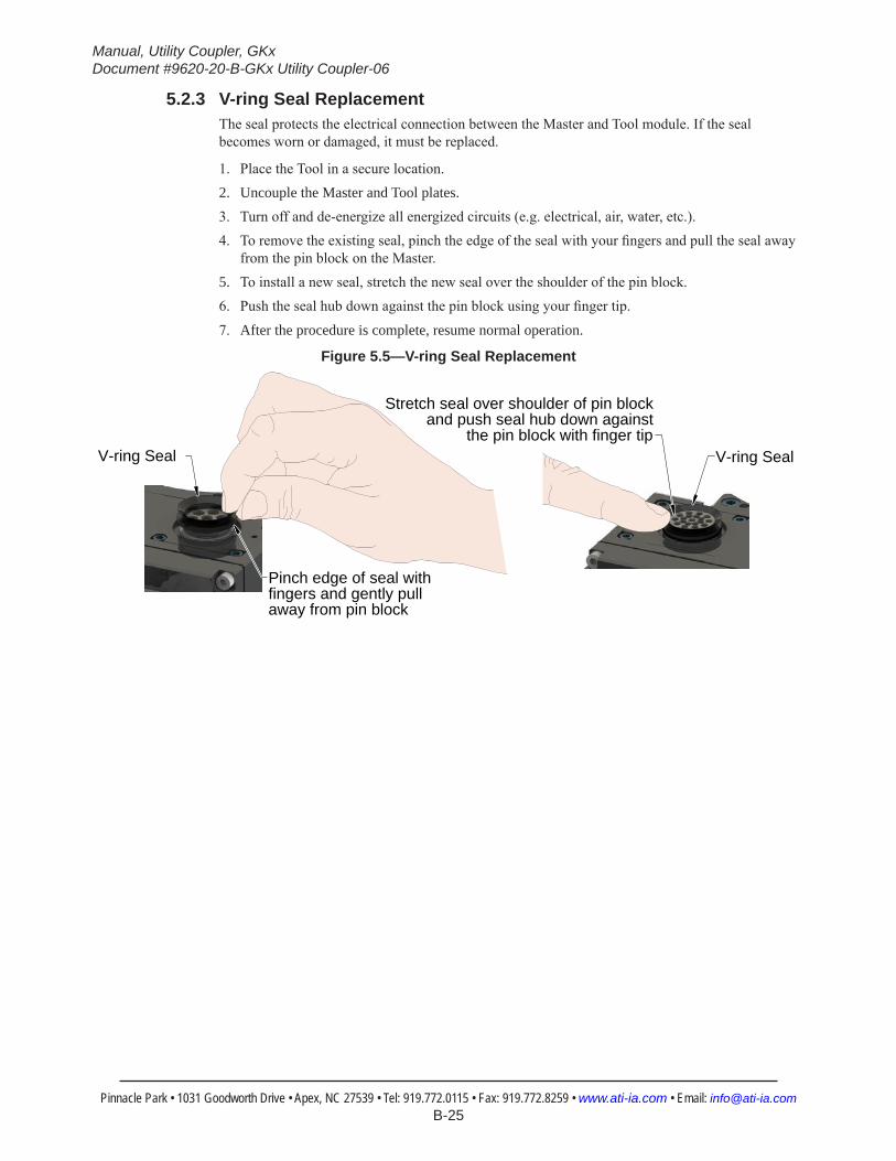
5.2.3 V-ring Seal ReplacementThe seal protects the electrical connection between the Master and Tool module. If the seal becomes worn or damaged, it must be replaced.
1. Place the Tool in a secure location.2. Uncouple the Master and Tool plates.3. Turn off and de-energize all energized circuits (e.g. electrical, air, water, etc.).4. To remove the existing seal, pinch the edge of the seal with your fingers and pull the seal away
from the pin block on the Master.5. To install a new seal, stretch the new seal over the shoulder of the pin block.6. Push the seal hub down against the pin block using your finger tip.
7. After the procedure is complete, resume normal operation.
Figure 5.5—V-ring Seal Replacement
V-ring Seal
Stretch seal over shoulder of pin block and push seal hub down against
the pin block with finger tipV-ring Seal
Pinch edge of seal with fingers and gently pull away from pin block

Manual, Utility Coupler, GKxDocument #9620-20-B-GKx Utility Coupler-06
Pinnacle Park • 1031 Goodworth Drive • Apex, NC 27539 • Tel: 919.772.0115 • Fax: 919.772.8259 • www.ati-ia.com • Email: [email protected] B-26
5.2.4 Tool Presence Sensor Replacement for GK UnitsParts Required: Refer to Section 6—Serviceable PartsTools Required: 1/2” socket wrench, Torque wrenchSupplies Required: Loctite 222
1. Uncouple the Utility Coupler to allow clear access to the Master and Tool plates.2. Turn off and de-energize all energized circuits (e.g. electrical, air, water, etc.). 3. Disconnect the sensor cable, loosening the lock nut using a 1/2” socket wrench, and unscrewing
the sensor from the body.4. Check to be sure the female threads on the housing are free and clear of debris, then thread a
new sensor into the Tool presence mounting holes until the face of the sensor is flush or 0.010ʺ below flush with the coupling face of the Master assembly.
5. Apply Loctite 222 to the exposed threaded area of the sensor where the lock nut will seat (only this area).
6. Screw the lock nut onto the sensor until it is snug to the Master body using a 1/2” socket wrench. Tighten to 20 in-lbs (2.26 Nm).
7. Connect the sensor cable.8. If repairs are complete, return circuits to normal operation.
Figure 5.6—Tool Presence Sensor Replacement (GL5CM Shown)

Manual, Utility Coupler, GKxDocument #9620-20-B-GKx Utility Coupler-06
Pinnacle Park • 1031 Goodworth Drive • Apex, NC 27539 • Tel: 919.772.0115 • Fax: 919.772.8259 • www.ati-ia.com • Email: [email protected] B-27
5.2.5 GK1CM Thrust Bearing, Chamfered Washer, and Shoulder Bolt ReplacementParts Required: Refer to Section 6—Serviceable PartsTools Required: 6 mm Allen wrench, Torque wrenchSupplies Required: Loctite 7649 and 242, Magnalube G lubricant, Clean ragRemove
1. Uncouple the Utility Coupler to allow clear access to the Master and Tool plates.2. Turn off and de-energize all energized circuits (e.g. electrical, air, water, etc.). 3. Press on Utility Coupler Master to compress the springs and release the pressure on the thrust
bearing, chamfered washer and shoulder bolt.4. Remove the M12 shoulder bolt using a 6 mm Allen wrench.5. Remove the chamfered washer and thrust bearing. Note: To remove the thrust bearing may
require the use of a flat head screw driver (or similar) to push bearing out from the back side.6. Clean the housing with a rag to remove grease and debris.Install
7. Apply Loctite Primer 7649 to the threads of the shoulder bolt.8. Insert the new thrust bearing with the chamfered side facing outward.9. Apply MobilGrease XHP222 Special grease the chamfered edges of the thrust bearing and the
new chamfered washer.10. Insert the new chamfered washer with the chamfer facing inward.11. Apply Loctite 242 to the threads of the new shoulder bolt.12. Press on Utility Coupler Master to compress the springs so that the shoulder bolt will bottom
out in the housing and leave the thrust bearing and chamfered washer loose.
Figure 5.7—GK1CM Thrust Bearing, Chamfered Washer, and Shoulder Bolt Replacement
Clean the Housing prior toInstalling new Thrust Bearing
Thrust Bearing
Chamfered Washer
Shoulder Bolt
Apply Loctite Primer 7649 and Loctite 242 to Threads on Shoulder Bolt
Orient Thrust Bearing with Chamfered side facing outward
Orient Chamfered Washer Chamfered side facing inward
Press on Utility Coupler Master to Compress Springs and shoulder Bolt will Bottom out in Housing
13. Insert the new shoulder bolt and tighten the new shoulder bolt using 6 mm Allen wrench to 250 in-lbs (28.25 Nm).
14. If repairs are complete, return circuits to normal operation.

Manual, Utility Coupler, GKxDocument #9620-20-B-GKx Utility Coupler-06
Pinnacle Park • 1031 Goodworth Drive • Apex, NC 27539 • Tel: 919.772.0115 • Fax: 919.772.8259 • www.ati-ia.com • Email: [email protected] B-28
5.2.6 GK2CM Thrust Bearing, Chamfered Washer, and Shoulder Bolt ReplacementParts Required: Refer to Section 6—Serviceable PartsTools Required: 6 mm Allen wrench, Torque wrenchSupplies Required: Loctite 7649 and 242, Magnalube G lubricant, Clean ragRemove
1. Uncouple the Utility Coupler to allow clear access to the Master and Tool plates.2. Turn off and de-energize all energized circuits (e.g. electrical, air, water, etc.). 3. Press on Utility Coupler Master to compress the springs and release the pressure on the thrust
bearing, chamfered washer and shoulder bolt.4. Remove the M12 shoulder bolt and M10 hex nut using a 6 mm Allen wrench.5. Remove the chamfered washer and thrust bearing. Note: To remove the thrust bearing may
require the use of a flat head screw driver (or similar) to push bearing out from the back side.6. Clean the housing with a rag to remove grease and debris.Install
7. Apply Loctite Primer 7649 to the threads on the new shoulder bolt.8. Insert the new thrust bearing with the chamfered side facing outward.9. Apply MobilGrease XHP222 Special grease the chamfered edges of the thrust bearing and the
new chamfered washer.10. Insert the new chamfered washer with the chamfer facing inward.11. Apply Loctite 242 to the threads of new shoulder bolt.12. Press on Utility Coupler Master to compress the springs so that the shoulder bolt will bottom
out in the housing and leave the thrust bearing and chamfered washer loose.

Manual, Utility Coupler, GKxDocument #9620-20-B-GKx Utility Coupler-06
Pinnacle Park • 1031 Goodworth Drive • Apex, NC 27539 • Tel: 919.772.0115 • Fax: 919.772.8259 • www.ati-ia.com • Email: [email protected] B-29
Figure 5.8—GK2CM Thrust Bearing, Chamfered Washer, and Shoulder Bolt Replacement
Clean the Housing prior to Installing new Thrust Bearing
Thrust BearingChamfered
WasherShoulder
Bolt
M10 Hex Nut
Orient Chamfered Washer Chamfered side facing inward
Orient Thrust Bearing with Chamfered side facing outward
Press on Utility Coupler Master to Compress Springs and shoulder Bolt will Bottom out in Housing
Apply Loctite Primer 7649 to threads in NutApply Loctite 242 to Threads on Shoulder Bolt
13. Insert the new shoulder bolt and tighten the new shoulder bolt and hex nut, using 6 mm Allen wrench to 250 in-lbs (28.25 Nm).
14. If repairs are complete, return circuits to normal operation.

Manual, Utility Coupler, GKxDocument #9620-20-B-GKx Utility Coupler-06
Pinnacle Park • 1031 Goodworth Drive • Apex, NC 27539 • Tel: 919.772.0115 • Fax: 919.772.8259 • www.ati-ia.com • Email: [email protected] B-30
5.2.7 GK1CM Compliance Spring Replacement for Utility Coupler (Preferred Method)This method is preferred for a dirty or gritty environment. The fine threads of the compliant preload pusher can get filled with dirt and grit and be damaged when removing or installing the compliance springs. If the environment is free from debris or grit, use the alternative method. Refer to Section 5.2.8—GK1CM Compliance Spring Replacement for Utility Coupler (Alternate Method).Parts Required: Refer to Section 6—Serviceable PartsTools Required: 6 mm Allen wrench, Torque wrenchSupplies Required: Loctite 7649 and 242, Magnalube G lubricant, Compressed air, Clean rag
1. Uncouple the Utility Coupler to allow clear access to the Master and Tool plates.2. Turn off and de-energize all energized circuits (e.g. electrical, air, water, etc.). 3. Remove Utility Coupler Master from drive cylinder refer to Section 2.2—Utility Coupler
Master Removal.4. Clear dust and debris out of spring compliance area by blowing with compressed air in the gap
between the interface plate and the Utility Coupler body.5. Remove the (3) shoulder bolts, thrust washers, and chamfered washers, refer to Section 5.2.5—
GK1CM Thrust Bearing, Chamfered Washer, and Shoulder Bolt Replacement (Remove).6. Lift off the Master body to expose the compression springs.
Figure 5.9—GK1CM Compliance Springs Replacement (Preferred Method)
(3) Compliance Springs
Back Plate
Master Body
(3) Shoulder Bolts
(3) Chamfered Washers
(3) Thrust Bearings
7. Replace compression springs as necessary. Note: If an individual compression spring is worn out or broken it is recommended that all compression spring be replaced.
8. Place the Master body on the compliance interface plate, making sure the compression springs are in the proper recesses in the back of the Master body.
9. Replace the (3) shoulder bolts, thrust washers, and chamfered washers, refer to Section 5.2.5—GK1CM Thrust Bearing, Chamfered Washer, and Shoulder Bolt Replacement (Install).
10. Install the Utility Coupler Master to the drive cylinder refer to Section 2.1—Utility Coupler Master Installation.
11. If repairs are complete, return circuits to normal operation.

Manual, Utility Coupler, GKxDocument #9620-20-B-GKx Utility Coupler-06
Pinnacle Park • 1031 Goodworth Drive • Apex, NC 27539 • Tel: 919.772.0115 • Fax: 919.772.8259 • www.ati-ia.com • Email: [email protected] B-31
5.2.8 GK1CM Compliance Spring Replacement for Utility Coupler (Alternate Method)The alternative method can be used for environments that are free of dirt and grit. The fine threads of the compliant preload pusher can get filled with dirt and grit and be damaged when removing or installing the compliance springs. If environment is dirty or gritty use the preferred method, refer to Section 5.2.7—GK1CM Compliance Spring Replacement for Utility Coupler (Preferred Method).Parts Required: Refer to Section 6—Serviceable PartsTools Required: 5/16” Allen wrench Supplies Required: Loctite 222, Compressed air, Clean rag
1. Uncouple the Utility Coupler to allow clear access to the Master and Tool plates.2. Turn off and de-energize all energized circuits (e.g. electrical, air, water, etc.). 3. Remove Utility Coupler Master from drive cylinder refer to Section 2.2—Utility Coupler
Master Removal.4. Clear dust and debris out of spring compliance area by blowing with compressed air in the gap
between the interface plate and the Utility Coupler body.
Figure 5.10—GK1CM Compliance Springs Replacement (Alternative Method)
Compliance Spring
Compliant Preload PusherApply Lotite 222 to Threads
0.08" to 0.125" Depth for Compliant Preload Pusher
5. Using a 5/16ʺ Allen wrench, remove the compliant preload pusher from the interface plate.6. Remove the (2) compression springs.7. Insert (2) new compression springs.8. Apply Loctite 222 to the threads of the new compliant preload pusher.9. Using a 5/16ʺ Allen wrench, tighten the compliant preload pusher until it is 0.08ʺ to 0.125ʺ
below the face of the interface plate.10. Install the Utility Coupler Master to the drive cylinder refer to Section 2.1—Utility Coupler
Master Installation.11. If repairs are complete, return circuits to normal operation.

Manual, Utility Coupler, GKxDocument #9620-20-B-GKx Utility Coupler-06
Pinnacle Park • 1031 Goodworth Drive • Apex, NC 27539 • Tel: 919.772.0115 • Fax: 919.772.8259 • www.ati-ia.com • Email: [email protected] B-32
5.2.9 GK2CM Compliance Spring Replacement for Utility Coupler (Preferred Method)This method is preferred for a dirty or gritty environment. The fine threads of the compliant preload pusher can get filled with dirt and grit and be damaged when removing or installing the compliance springs. If the environment is free from debris or grit, use the alternative method. Refer to Section 5.2.10—GK2CM Compliance Spring Replacement for Utility Coupler (Alternate Method).Parts Required: Refer to Section 6—Serviceable PartsTools Required: 6 mm Allen wrench, Torque wrenchSupplies Required: Loctite 7649 and 242, Magnalube G lubricant, Compressed air, Clean rag
1. Uncouple the Utility Coupler to allow clear access to the Master and Tool plates.2. Turn off and de-energize all energized circuits (e.g. electrical, air, water, etc.). 3. Remove Utility Coupler Master from drive cylinder refer to Section 2.2—Utility Coupler
Master Removal.4. Clear dust and debris out of spring compliance area by blowing with compressed air in the gap
between the interface plate and the Utility Coupler body.5. Remove the (3) shoulder bolts, thrust washers, and chamfered washers, refer to Section 5.2.5—
GK1CM Thrust Bearing, Chamfered Washer, and Shoulder Bolt Replacement (Remove).6. Lift off the Master body to expose the compression springs.
Figure 5.11—GK2CM Compliance Springs Replacement (Preferred Method)
(2) Outer Compression Springs
(2) Inner Compression SpringsMaster Body
(2) Shoulder Bolt
(2) Chamfered Washer
(2) Thrust Bearing
Back Plate
(2) M10 Hex Nut
7. Replace compression springs as necessary. Note: If an individual compression spring is worn out or broken it is recommended that all compression spring be replaced.
8. Place the Master body on the compliance interface plate, making sure the compression springs are in the proper recesses in the back of the Master body.
9. Replace the (3) shoulder bolts, thrust washers, and chamfered washers, refer to Section 5.2.5—GK1CM Thrust Bearing, Chamfered Washer, and Shoulder Bolt Replacement (Install).
10. Install the Utility Coupler Master to the drive cylinder refer to Section 2.1—Utility Coupler Master Installation.
11. If repairs are complete, return circuits to normal operation.

Manual, Utility Coupler, GKxDocument #9620-20-B-GKx Utility Coupler-06
Pinnacle Park • 1031 Goodworth Drive • Apex, NC 27539 • Tel: 919.772.0115 • Fax: 919.772.8259 • www.ati-ia.com • Email: [email protected] B-33
5.2.10 GK2CM Compliance Spring Replacement for Utility Coupler (Alternate Method)The alternative method can be used for environments that are free of dirt and grit. The fine threads of the compliant preload pusher can get filled with dirt and grit and be damaged when removing or installing the compliance springs. If environment is dirty or gritty use the preferred method, refer to Section 5.2.9—GK2CM Compliance Spring Replacement for Utility Coupler (Preferred Method).Parts Required: Refer to Section 6—Serviceable PartsTools Required: 5/16” Allen wrench Supplies Required: Loctite 222, Compressed air, Clean rag
1. Uncouple the Utility Coupler to allow clear access to the Master and Tool plates.2. Turn off and de-energize all energized circuits (e.g. electrical, air, water, etc.). 3. Clear dust and debris out of spring compliance area by blowing with compressed air in the gap
between the interface plate and the Utility Coupler body.
Figure 5.12—GK2CM Compliance Springs Replacement (Alternative Method)
Compression Springs
Compression Springs
Compliant Preload Pusher Apply Loctite 222 to Threads
0.36" to 0.38" Depth forCompliant Preload Pusher
4. Using a 5/16ʺ Allen wrench, remove the compliant preload pusher from the interface plate.5. Remove the (2) compression springs.6. Insert (2) new compression springs.7. Apply Loctite 222 to the threads of the new compliant preload pusher.8. Using a 5/16ʺ Allen wrench, tighten the compliant preload pusher until it is 0.36ʺ to 0.38ʺ below
the face of the interface plate.9. If repairs are complete, return circuits to normal operation.

Manual, Utility Coupler, GKxDocument #9620-20-B-GKx Utility Coupler-06
Pinnacle Park • 1031 Goodworth Drive • Apex, NC 27539 • Tel: 919.772.0115 • Fax: 919.772.8259 • www.ati-ia.com • Email: [email protected] B-34
5.2.11 Center Swivel Replacement for Utility CouplerParts Required: Refer to Section 6—Serviceable PartsTools Required: 6 mm Allen wrench, 8 mm Allen wrench, Torque wrenchSupplies Required: Loctite 7649, 242, and 271, Magnalube G lubricant, Compressed air, Clean rag
1. Uncouple the Utility Coupler to allow clear access to the Master and Tool plates.2. Turn off and de-energize all energized circuits (e.g. electrical, air, water, etc.). 3. Remove Utility Coupler Master from drive cylinder refer to Section 2.2—Utility Coupler
Master Removal.4. Clear dust and debris out of spring compliance area by blowing with compressed air in the gap
between the interface plate and the Utility Coupler body, refer to Section 4.4—Clear Dust and Debris from Compliance Springs Area.
5. Remove the (3) shoulder bolts, thrust washers, and chamfered washers, refer to Section 5.2.5—GK1CM Thrust Bearing, Chamfered Washer, and Shoulder Bolt Replacement (Remove).
6. Lift off the Master body to expose the center pivot.7. Using a 8 mm Allen wrench, remove the set screw and ball tip set screw.
Figure 5.13—Position the Center Swivel
.120
.110 Ball Protrusion Seated Position
(Installed set screw should be below flush)
Set Screw Apply Loctite Primer 7649 and then Loctite 271) (Torque to 150 in-lbs)
Ball Tip Set Screw (Apply Loctite Primer 7649and then Loctite 271)
Utility Coupler Master(Side Toward the Compliance Plate)
8. Apply Loctite Primer 7649 and then Loctite 271 to the threads of the new ball tip set screw.9. Using a 8 mm Allen wrench, install the new ball tip set screw. Position the ball tip set screw so
that the ball tip protrudes between .110” and .120” from the surface of the Utility Coupler body.10. Allow 5 minutes for the Loctite to dry before proceeding to the next step.11. Apply Loctite Primer 7649 and then Loctite 271 to the threads of the set screw.12. Using a 8 mm Allen wrench, install the set screw. Tighten to 150 in-lbs (16.95 Nm).13. Place the Master body on the compliance interface plate, making sure the compression springs
are in the proper recesses in the back of the Master body.14. Replace the (3) shoulder bolts, thrust washers, and chamfered washers, refer to Section 5.2.5—
GK1CM Thrust Bearing, Chamfered Washer, and Shoulder Bolt Replacement (Install).15. Install the Utility Coupler Master to the drive cylinder refer to Section 2.1—Utility Coupler
Master Installation.16. If repairs are complete, return circuits to normal operation.

Manual, Utility Coupler, GKxDocument #9620-20-B-GKx Utility Coupler-06
Pinnacle Park • 1031 Goodworth Drive • Apex, NC 27539 • Tel: 919.772.0115 • Fax: 919.772.8259 • www.ati-ia.com • Email: [email protected] B-35
5.2.12 GK1CM Alignment Pin ReplacementParts Required: Refer to Section 6—Serviceable PartsTools required: 5 mm Allen wrench, Torque wrenchSupplies required: Magnalube G lubricant
1. Uncouple the Utility Coupler and space to allow clear access to the Master and Tool.2. Turn off all energized circuits (e.g., electrical, air, water, etc.)3. Remove the M6 socket head cap screw using a 5 mm Allen wrench.4. Remove the alignment pin from the housing.
NOTICE:Ifthealignmentpinisdifficulttoremove,itcanbeknockedoutusinga0.1”diameter pin from the back side of the housing.
5. Insert the new alignment pin into the housing, align the tapped hole in the pin with the M6 screw hole in the housing.
Figure 5.14—GK1CM Alignment Pin Replacement
Alignment Pin
M6 Socket HeadCap Screw
M6 Threaded Hole
6. Secure the alignment pin with the M6 socket head cap screw using a 5 mm Allen wrench, and tighten to 140 in-lbs (15.82 Nm).
7. Apply MobilGrease XHP222 Special grease to the alignment pin.8. If repairs are complete, return circuits to normal operation.

Manual, Utility Coupler, GKxDocument #9620-20-B-GKx Utility Coupler-06
Pinnacle Park • 1031 Goodworth Drive • Apex, NC 27539 • Tel: 919.772.0115 • Fax: 919.772.8259 • www.ati-ia.com • Email: [email protected] B-36
5.2.13 GK2CM Alignment Pin ReplacementRefer to Figure 5.15 and Figure 5.16Parts required: Refer to Section 2.1—Utility Coupler Master InstallationTools required: 3 mm, 4 mm, and 5 mm Allen wrench (hex key), torque wrenchSupplies required: Clean rag, MobilGrease XHP222, Loctite 242
1. Place the Tool safely in the tool stand. Uncouple the Tool Changer to allow clear access to the Master and Tool plates.
2. Turn off and de-energize all energized circuits (e.g. electrical, air, water, etc.). 3. Unscrew the alignment pin assembly from the Master plate using a 4 mm Allen wrench. If
alignment was remove, verify that the assembly (pin and set screw) are intact. If the set screw portion of the assembly did not come out, it will be necessary to remove it separately using the access hole in the back plate of the Master plate go to step 4. If the alignment pin and set screw were removed, go to step 6. If alignment pin cannot be removed using the Allen wrench in the tip, go to step 4.
NOTICE: If for any reason the pin cannot be removed using the Allen wrench in the tip, it may be necessary to remove it by other means, such as locking pliers.
Figure 5.15—GK2CM Alignment Pin Replacement
4 mm Allen Wrench
RatchetHex Socket
Alignment Pin
Set Screw with Hex
Socket

Manual, Utility Coupler, GKxDocument #9620-20-B-GKx Utility Coupler-06
Pinnacle Park • 1031 Goodworth Drive • Apex, NC 27539 • Tel: 919.772.0115 • Fax: 919.772.8259 • www.ati-ia.com • Email: [email protected] B-37
4. Another approach would be to use the access hole in the back side of the Master plate. If not already removed, remove the Master plate refer to Section 2.2—Utility Coupler Master Removal. Use a 3 mm Allen wrench to remove the alignment pin from the back side of the Master plate. Refer to Figure 5.16).
Figure 5.16—GK2CM Alignment Pin Replacement Alternate Method
Alignment Pin
3 mm Allen Wrench
Set Screw with Hex Socket
5. Once the alignment pin has been removed, install the Master plate, refer to Section 2.1—Utility Coupler Master Installation.
6. Apply Loctite 242 and install the alignment pin assembly into the bushing on the Tool Changer. Tighten to 60 in-lbs (6.8 Nm).
7. Apply MobilGrease XHP222 Special grease to the alignment pin (see Section 4.2—Clean, Inspect, and Lubricate Thrust Bearings for Utility Couplers).
8. If repairs are complete, return circuits to normal operation.
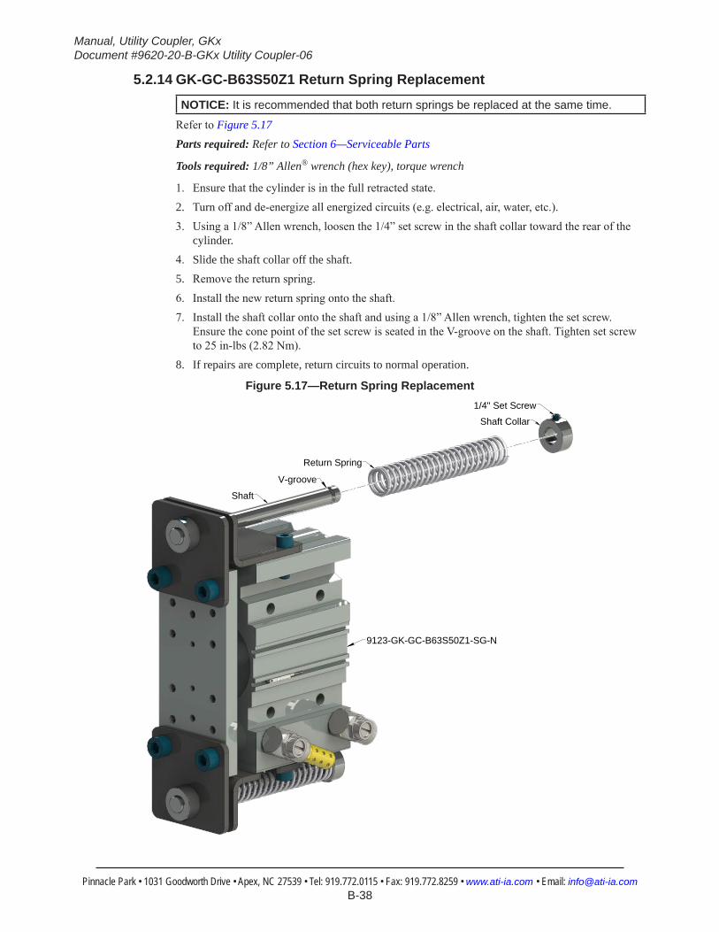
Manual, Utility Coupler, GKxDocument #9620-20-B-GKx Utility Coupler-06
Pinnacle Park • 1031 Goodworth Drive • Apex, NC 27539 • Tel: 919.772.0115 • Fax: 919.772.8259 • www.ati-ia.com • Email: [email protected] B-38
5.2.14 GK-GC-B63S50Z1 Return Spring Replacement
NOTICE: It is recommended that both return springs be replaced at the same time.
Refer to Figure 5.17Parts required: Refer to Section 6—Serviceable Parts
Tools required: 1/8” Allen® wrench (hex key), torque wrench
1. Ensure that the cylinder is in the full retracted state.2. Turn off and de-energize all energized circuits (e.g. electrical, air, water, etc.). 3. Using a 1/8” Allen wrench, loosen the 1/4” set screw in the shaft collar toward the rear of the
cylinder.4. Slide the shaft collar off the shaft.5. Remove the return spring.6. Install the new return spring onto the shaft.7. Install the shaft collar onto the shaft and using a 1/8” Allen wrench, tighten the set screw.
Ensure the cone point of the set screw is seated in the V-groove on the shaft. Tighten set screw to 25 in-lbs (2.82 Nm).
8. If repairs are complete, return circuits to normal operation.
Figure 5.17—Return Spring Replacement
9123-GK-GC-B63S50Z1-SG-N
Shaft
Return Spring
Shaft Collar
1/4" Set Screw
V-groove
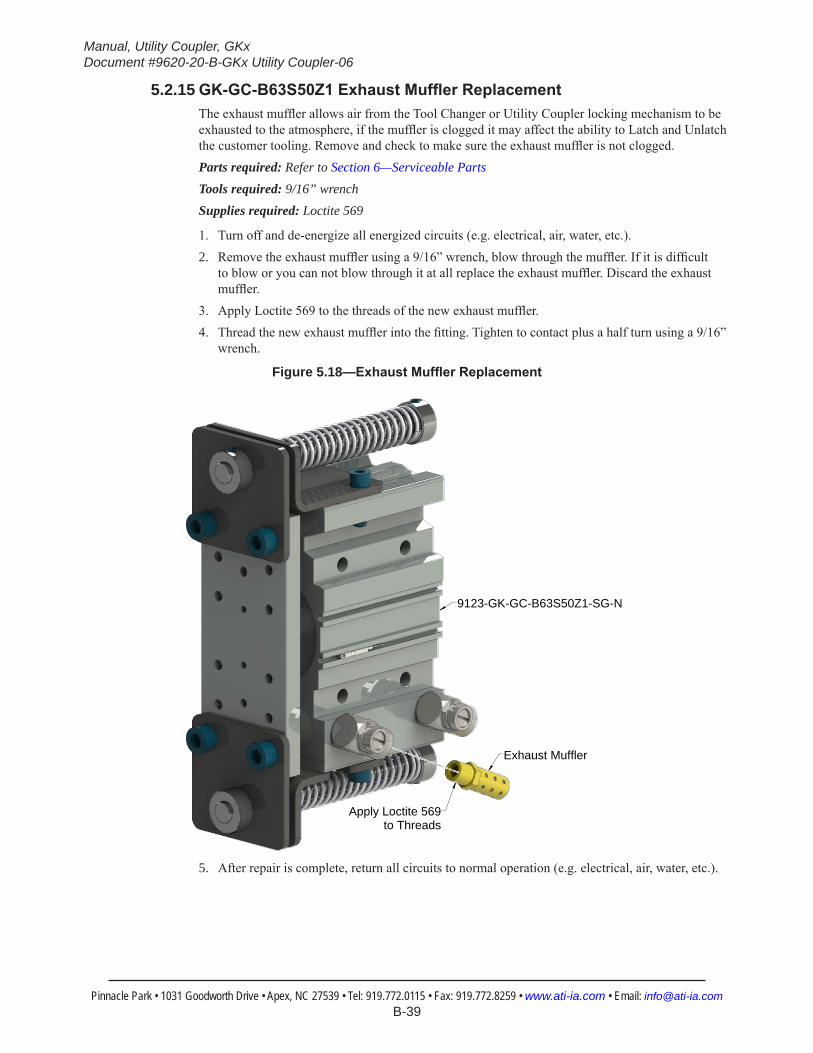
Manual, Utility Coupler, GKxDocument #9620-20-B-GKx Utility Coupler-06
Pinnacle Park • 1031 Goodworth Drive • Apex, NC 27539 • Tel: 919.772.0115 • Fax: 919.772.8259 • www.ati-ia.com • Email: [email protected] B-39
5.2.15 GK-GC-B63S50Z1ExhaustMufflerReplacementThe exhaust muffler allows air from the Tool Changer or Utility Coupler locking mechanism to be exhausted to the atmosphere, if the muffler is clogged it may affect the ability to Latch and Unlatch the customer tooling. Remove and check to make sure the exhaust muffler is not clogged.Parts required: Refer to Section 6—Serviceable PartsTools required: 9/16” wrenchSupplies required: Loctite 569
1. Turn off and de-energize all energized circuits (e.g. electrical, air, water, etc.).2. Remove the exhaust muffler using a 9/16” wrench, blow through the muffler. If it is difficult
to blow or you can not blow through it at all replace the exhaust muffler. Discard the exhaust muffler.
3. Apply Loctite 569 to the threads of the new exhaust muffler.4. Thread the new exhaust muffler into the fitting. Tighten to contact plus a half turn using a 9/16”
wrench.
Figure 5.18—ExhaustMufflerReplacement
Apply Loctite 569to Threads
Exhaust Muffler
9123-GK-GC-B63S50Z1-SG-N
5. After repair is complete, return all circuits to normal operation (e.g. electrical, air, water, etc.).

Manual, Utility Coupler, GKxDocument #9620-20-B-GKx Utility Coupler-06
Pinnacle Park • 1031 Goodworth Drive • Apex, NC 27539 • Tel: 919.772.0115 • Fax: 919.772.8259 • www.ati-ia.com • Email: [email protected] B-40
6. Serviceable Parts6.1 GK1 Compliant Utility Coupler Master (9123-GK1CM-0-0-0-0)
10
14
611
12
3
78
1
4
4
12
2
2
15
13
9
Figure 6.1—Master Plate Item No. Qty Part Number Description
1 1 9123-GK1CM-0-0-0-0 GK1 Compliance Utility Coupler Base Assembly
2 4 3500-1066016-15A M6 x 16 mm socket head cap screws Blue Dyed Magni ND Microspheres
3 3 3500-2070035-11 SHCS Shoulder M12 x 35 Shoulder M10 Thread
5 3 3610-2520001-11 Steel Spring 15/16" OD, 2" Long 15.54Rate
6 1 3690-6600900-10 Rolling Ball Tip Set Screw, M16-2.0 x 23.3 mm long, Black Oxide Steel
7 3 3700-20-4675 Custom Chamfered Washer
8 3 3700-20-4676 Custom SAE 841 Bronze Thrust Bearing
9 3 3700-20-4716 Compliant IP Preload Pusher
10 1 3700-20-4875 1/2" Dia. Utility Coupler Alignment Pin 4 mm Taper, Short Diamond
11 1 3700-20-4876 1/2" Dia. Utility Coupler Alignment Pin 4 mm Taper, Short, Round
12 2 3500-1066012-15A M6 x 12 mm socket head cap screws Blue Dyed Magni ND Microspheres
13 1 3700-20-6070 G4 Master Back Plate
14 1 3700-20-8254 M16-2.0 x 9 mm Set Screw, Hollow Hex
9123-GK1CM-0-0-0-0-SE4 2 8590-9909999-120 NPN Proximity Sensor
9123-GK1CM-0-0-0-0-SG4 2 8590-9909999-34 PNP Proximity Sensor

Manual, Utility Coupler, GKxDocument #9620-20-B-GKx Utility Coupler-06
Pinnacle Park • 1031 Goodworth Drive • Apex, NC 27539 • Tel: 919.772.0115 • Fax: 919.772.8259 • www.ati-ia.com • Email: [email protected] B-41
6.2 GK2 Compliant Utility Coupler Master (9123-GK2CM-0-00-0-00-N/E/R)
20
11
514
15
17
213
312
189
16
7
1
7
4
8
10
196
Figure 6.2—Master Plate Item No. Qty Part Number Description
1
1 9123-GK2CM-0-00-0-00-N GK2 Compliant Utility Coupler Base Assembly, (2) 3/8 NPT Checked Air Ports
1 9123-GK2CM-0-00-0-00-E GK2 Compliant Utility Coupler Base Assembly, (2) G 3/8 BSPP Checked Air Ports
1 9123-GK2CM-0-00-0-00-R GK2 Compliant Utility Coupler Base Assembly, (2) Rc 3/8 BSPT Checked Air Ports
2 2 3410-0001065-01 O-Ring 14 mm X 2 mm Buna
3 2 3410-0001183-01 O-Ring 6 mm X 2 mm Buna D90
4 4 3500-1066016-15A M6 x 16 mm socket head cap screws Blue Dyed Magni ND Microspheres
5 2 3500-2070035-11 SHCS Shoulder M12 x 35 Shoulder M10 Thread
6 2 3505-0870001-12 Hex Nut M10x1.5, 8 mm Tall 17 mm Wide Zinc Plated Steel
8 2 3610-1725001-10 Steel Compression Spring 2-1/2" L, 5/8" OD,.080" Wire
9 2 3610-1907501-21 SS SPRING 7/8 OD
10 2 3610-2520001-11 Steel Spring 15/16" OD, 2" Long 15.54Rate
11 1 3690-6600900-10 Rolling Ball Tip Set Screw, M16-2.0 x 23.3 mm long, Black Oxide Steel
12 2 3700-20-2994 Master Check Valve Piston, FA44
13 2 3700-20-3488 Valve Stem
14 2 3700-20-4675 Custom Chamfered Washer
15 2 3700-20-4676 Custom SAE 841 Bronze Thrust Bearing

Manual, Utility Coupler, GKxDocument #9620-20-B-GKx Utility Coupler-06
Pinnacle Park • 1031 Goodworth Drive • Apex, NC 27539 • Tel: 919.772.0115 • Fax: 919.772.8259 • www.ati-ia.com • Email: [email protected] B-42
Figure 6.2—Master Plate Item No. Qty Part Number Description
16 2 3700-20-4716 Compliant IP Preload Pusher
17 2 9005-20-2241 1/2" Two Piece Pin Assembly
18 2 3410-0001068-01 Mini U-Cup Seal 18 mm ID x 22 mm Buna
19 1 3700-20-7206 G4D Master Mount Plate
20 1 3700-20-8254 M16-2.0 x 9 mm Set Screw, Hollow Hex
9123-GK2CM-0-00-0-00-SG7 2 8590-9909999-120 NPN Proximity Sensors
9123-GK2CM-0-00-0-00-SE7 2 8590-9909999-120 PNP Proximity Sensors

Manual, Utility Coupler, GKxDocument #9620-20-B-GKx Utility Coupler-06
Pinnacle Park • 1031 Goodworth Drive • Apex, NC 27539 • Tel: 919.772.0115 • Fax: 919.772.8259 • www.ati-ia.com • Email: [email protected] B-43
6.3 GK1 Compliant Utility Coupler Tool 9123-GK1T-0-0-0-0
1
Figure 6.3—Tool Plate Item No. Qty Part Number Description
1 1 9123-GK1T-0-0-0-0 GK1 Utility Coupler Tool Base Assembly
6.4 GK2 Compliant Utility Coupler Tool 9123-GK2T-0-00-0-00-N/E/R
1
23
4
5
6
Figure 6.4—Tool Plate Item No. Qty Part Number Description
1
1 9123-GK2T-0-00-0-00-N GK2 Utility Coupler Tool with (2) Integrated checked 3/8 NPT Air Ports
1 9123-GK2T-0-00-0-00-E GK2 Utility Coupler Tool with (2) Integrated checked G 3/8 BSPP Air Ports
1 9123-GK2T-0-00-0-00-R GK2 Utility Coupler Tool with (2) Integrated checked Rc 3/8 BSPP Air Ports
2 2 3410-0001067-01 O-Ring 10 x 2.0 mm Buna-N D90
3 2 3700-20-2303 Check Valve
4 2 3610-6401501-21 SS Spring 14 mm O.D, 13.5#/in
5 2 3410-0001284-01 O-Ring .669 ID x .047, 70 Durometer Buna-N
6 2 3700-20-3288 Plug, Tool, Plastic (Threaded Modules)

Manual, Utility Coupler, GKxDocument #9620-20-B-GKx Utility Coupler-06
Pinnacle Park • 1031 Goodworth Drive • Apex, NC 27539 • Tel: 919.772.0115 • Fax: 919.772.8259 • www.ati-ia.com • Email: [email protected] B-44
6.5 Models 9123-GK-GC-B63S50Z1-SG-N
1
2
3
4
5
6
7
8
9
3
4
10
Figure 6.5—Guided Cylinder Item No. Qty Part Number Description
1 1 9123-GK-GC-B63S50Z1-SG-N GK Guided Cylinder Assembly, 63 mm Bore, 50 mm Stroke, PNP Sensor to Detect Retract, Custom Spring-Return
2 4 3500-1070020-15 M10 x 20 mm socket head cap screws, Blue Dyed Magni-565
3 4 3690-1604401-10 Shaft Collar, 1” OD x 1/2” ID x 7/16” W, 1/4”-20 Set Screw, Steel, Zinc Plated
4 4 3500-1924031-13 Set Screw 1/4”-20 x 5/16” Alloy Steel, Cone Point
5 2 3700-20-9679 Straight Bracket, Spring-Return GK2 Drive Cylinder
6 2 3690-1666001-10 1/2” Shaft, 6.6” Length, Steel, Hard Chrome, Case Hardened, V-Groove Both Ends
7 2 3700-20-9680 Angle Bracket, Spring-Return GK2 Drive Cylinder
8 4 3500-1068025-15A M8 x 25 mm socket head cap screws, Blue Dyed Magni-565 w/ ND Microspheres Epoxy
9 2 3610-1956301-10 Compression Spring, .875” OD, 5.63” Free Length, 16 lb/in, Steel, Zn
10 1 3490-1010004-00 MUFFLER, 1/4NPT, H-FLOW

Manual, Utility Coupler, GKxDocument #9620-20-B-GKx Utility Coupler-06
Pinnacle Park • 1031 Goodworth Drive • Apex, NC 27539 • Tel: 919.772.0115 • Fax: 919.772.8259 • www.ati-ia.com • Email: [email protected] B-45
6.6 Models 9123-GK-GC-B50S75-SG-N, 9123-GK-GC-B63S75-SG-N
1
Figure 6.6—Guided Cylinder Item No. Qty Part Number Description
1 19123-GK-GC-B50S75-SG-N GK Guided Cylinder Assembly, 50 mm Bore, 75 mm Stroke, PNP Sensor
to Detect Retract
9123-GK-GC-B63S75-SG-N GK Guided Cylinder, Pneumatic, NPT, 63 mm Bore, 75 mm Stroke, PNP 3 Wire Position Sensor
6.7 Models 9123-GK-GCE-PM24400-B-SG, 9123-GK-GCE2-PM24600-B-SG
1
2
Figure 6.7—Guided Cylinder Item No. Qty Part Number Description
1 19123-GK-GCE-PM24400-B-SG Utility Coupler Drive Unit, Electric, Perm Magnet Motor, 24VDC, 4.00"
Stroke, Brake Opt, (1) DC PNP
9123-GK-GCE2-PM24600-B-SG GK Utility Coupler Drive Unit, Electric, Perm Magnet Motor, 24VDC, 6.00” Stroke, Brake Opt, (1) DC P
2 1 8590-9909999-34 True 2 PNP Proximity Sensor

Manual, Utility Coupler, GKxDocument #9620-20-B-GKx Utility Coupler-06
Pinnacle Park • 1031 Goodworth Drive • Apex, NC 27539 • Tel: 919.772.0115 • Fax: 919.772.8259 • www.ati-ia.com • Email: [email protected] B-46
7. SpecificationsTable 7.1—Utility Couplers
9123-GK1 - Master and Tool Plates
Suggested Payload Limit Not applicableFixture weight should be supported independently of the Utility Coupler
Weight (coupled) 6.57 lb (2.9 kg) Master 3.61 lb, Tool 2.96 lbMin Recommended distance between Master and Tool plate 1.97 in (50 mm)
Min Required Force to Couple 40 lbs (18.14 kg) Base Model only, no modules attached
Mounting Interface Master and ToolRectangular Pattern ,See Section 8.1—GK1 Compliant Utility Coupler Drawings
9123-GK2-N/E/R - Master and Tool Plates
Suggested Payload Limit Not applicableFixture weight should be supported independently of the Utility Coupler
Weight (coupled) 5.44 lb (2.47 kg) Master 3.34 lb, Tool 2.10 lbMin Recommended distance between Master and Tool plate 1.97 in (50 mm)
Min Required Force to Couple 220 lbs (99.8 kg)
Base Model only, no modules attached. Assuming both integrated checked ports are pressurized to 80 psi.
Integrated Ports (2) 3/8 NPT Checked Ports Master and Tool, Air Only
Mounting Interface Master and Tool
Rectangular Pattern Section 8.2—GK2-N Compliant Utility Coupler DrawingsSection 8.3—GK2-E Compliant Utility Coupler DrawingsSection 8.4—GK2-R Compliant Utility Coupler Drawings

Manual, Utility Coupler, GKxDocument #9620-20-B-GKx Utility Coupler-06
Pinnacle Park • 1031 Goodworth Drive • Apex, NC 27539 • Tel: 919.772.0115 • Fax: 919.772.8259 • www.ati-ia.com • Email: [email protected] B-47
Table 7.2—Guilded Cyclinders9123-GK-GC-B50S75-SG-NBore Size 50 mmMax Stroke Length 75 mmRecommended Stroke Length 50 mmMax Coupling Force @ 80 psi 240 lbs (109 kg)Mounting Interface See Section 8.5—GK-GC-B50S75-SG-N9123-GK-GC-B63S75-SG-NBore Size 63 mmMax Stroke Length 75 mmRecommended Stroke Length 50 mmMax Coupling Force @ 80 psi 383 lbs (174 kg)Mounting Interface See Section 8.7—GK-GC-B63S75-SG-N9123-GK-GC-B63S50Z1-SG-NBore Size 63 mmMax Stroke Length 50 mmRecommended Stroke Length 40 mmMax Coupling Force @ 80 psi 303 lbs (137 kg)Mounting Interface See Section 8.6—GK-GC-B63S50Z1-SG-N9123-GK-GCE-PM24400-B-SG
Max Coupling Force @ 24 VDC, 6 Amps 75 lbs Estimated Axial holding force of brake on electrical drive unit.
Max Stroke Length 4 inchesMounting Interface See Section 8.9—GK-GCE-PM24400-B-SG9123-GK-GCE2-PM24600-B-SG
Max Coupling Force @ 24 VDC, 6 Amps 144 lbs Estimated Axial holding force of brake on electrical drive unit.
Max Stroke Length 6 inchesMounting Interface See Section 8.8—GK-GCE2-PM24600-B-SG
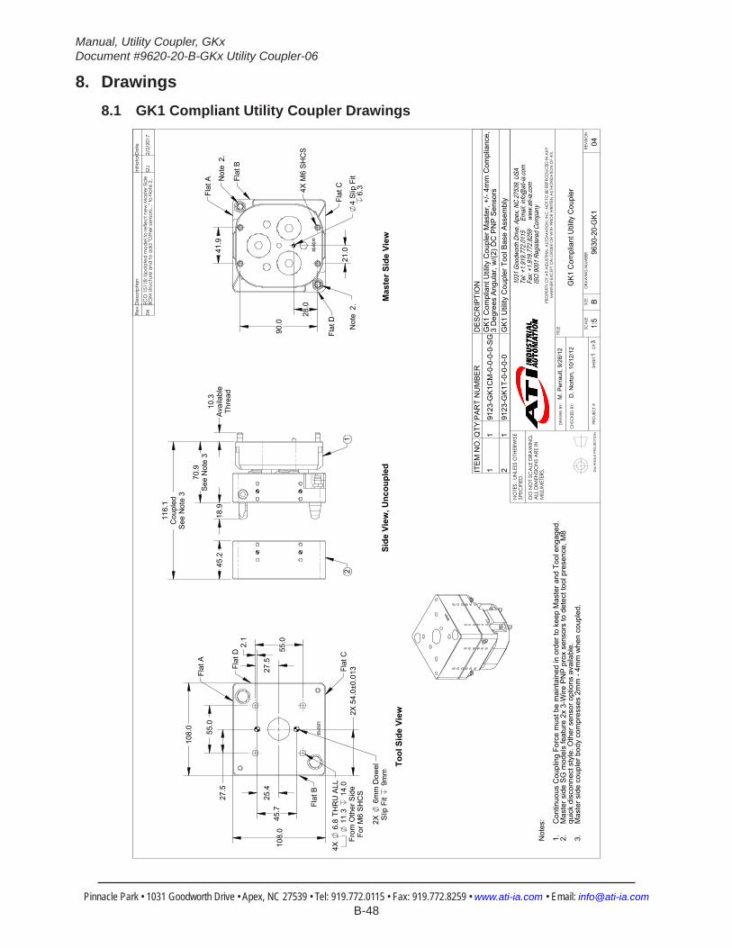
Manual, Utility Coupler, GKxDocument #9620-20-B-GKx Utility Coupler-06
Pinnacle Park • 1031 Goodworth Drive • Apex, NC 27539 • Tel: 919.772.0115 • Fax: 919.772.8259 • www.ati-ia.com • Email: [email protected] B-48
8. Drawings8.1 GK1 Compliant Utility Coupler Drawings
3rd
AN
GLE
PRO
JEC
TION
45.
2
116.
1C
oupl
edS
ee N
ote
3
10.3
Ava
ilabl
eTh
read
70.9
See
Not
e 3
18.
9
21
25.4
45.7
27.5
55.0
Slip
Fit
9m
m2X
6
mm
Dow
el
27.5
55.0
For M
6 S
HC
SFr
om O
ther
Sid
e 1
1.3
1
4.0
4X
6.8
TH
RU
ALL
108
.0
108
.0
2.1
2X
54.
0±0.
013 Fl
at D
Flat
A
Flat
B
Flat
C
90.
0 28.
0
41.
9
21.
0 4
Slip
Fit
6.3
Flat
CFl
at D
Not
e 2.
Not
e 2.
Flat
B
Flat
A
4X M
6 S
HC
S
Not
es:
C
ontin
uous
Cou
plin
g Fo
rce
mus
t be
mai
ntai
ned
in o
rder
to k
eep
Mas
ter a
nd T
ool e
ngag
ed.
1.M
aste
r sid
e S
G m
odel
s fe
atur
e 2x
3-W
ire P
NP
pro
x se
nsor
s to
det
ect t
ool p
rese
nce,
M8
2.qu
ick
disc
onne
ct s
tyle
. Oth
er s
enso
r opt
ions
ava
ilabl
e.M
aste
r sid
e co
uple
r bod
y co
mpr
esse
s 2m
m -
4mm
whe
n co
uple
d.3.
Tool
Sid
e Vi
ewSi
de V
iew
, Unc
oupl
edM
aste
r Sid
e Vi
ew
Rev.
Des
crip
tion
Initi
ator
Dat
e
04EC
O 1
5118
; Upd
ated
mod
el to
refle
ct n
ew M
aste
r Sid
e BO
M st
ruct
ure
and
to a
dd
"Oth
er se
nsor
s..."
to N
ote
2.SZ
J2/
2/20
17
ITE
M N
O.Q
TYP
AR
T N
UM
BE
RD
ES
CR
IPTI
ON
11
9123
-GK
1CM
-0-0
-0-0
-SG
GK
1 C
ompl
iant
Util
ity C
oupl
er M
aste
r, +/
- 4m
m C
ompl
ianc
e,
3 D
egre
es A
ngul
ar, w
/(2) D
C P
NP
Sen
sors
21
9123
-GK
1T-0
-0-0
-0G
K1
Util
ity C
oupl
er T
ool B
ase
Ass
embl
y
B1:
51
3RE
VISI
ON
NO
TES:
UN
LESS
OTH
ERW
ISE
SPEC
IFIE
D.
DO
NO
T SC
ALE
DRA
WIN
G.
ALL
DIM
ENSI
ON
S A
RE IN
M
ILLIM
ETER
S.
DRA
WN
BY:
CHE
CKE
D B
Y:
M. P
erra
ult,
9/28
/12
D. N
orto
n, 1
0/12
/12
TITLE SC
ALE
SIZE
DRA
WIN
G N
UMBE
R
PRO
JEC
T #
SHEE
T
O
F 96
30-2
0-G
K1
04
PRO
PERT
Y O
F A
TI IN
DUS
TRIA
L A
UTO
MA
TION
, IN
C. N
OT
TO B
E RE
PRO
DUC
ED IN
AN
Y M
AN
NER
EXC
EPT
ON
ORD
ER O
R W
ITH P
RIO
R W
RITT
EN A
UTHO
RIZA
TION
OF
ATI.
1031
Goo
dwor
th Dr
ive, A
pex,
NC 27
539,
USA
Tel: +
1.919
.772.0
115
Em
ail: in
fo@ati
-ia.co
mFa
x: +1
.919.7
72.82
59
www
.ati-ia
.com
ISO
9001
Reg
ister
ed C
ompa
ny
G
K1 C
ompl
iant
Util
ity C
oupl
er

Manual, Utility Coupler, GKxDocument #9620-20-B-GKx Utility Coupler-06
Pinnacle Park • 1031 Goodworth Drive • Apex, NC 27539 • Tel: 919.772.0115 • Fax: 919.772.8259 • www.ati-ia.com • Email: [email protected] B-49
3rd
AN
GLE
PRO
JEC
TION
210
3
1
515
4
13
7
11
6
914
12
8
16
8
GK
1 C
ompl
iant
Util
ity C
oupl
er M
aste
r Ass
embl
y
Rev.
Des
crip
tion
Initi
ator
Dat
e
-Se
e Sh
eet1
--
B2:
32
3RE
VISI
ON
NO
TES:
UN
LESS
OTH
ERW
ISE
SPEC
IFIE
D.
DO
NO
T SC
ALE
DRA
WIN
G.
ALL
DIM
ENSI
ON
S A
RE IN
M
ILLIM
ETER
S.
DRA
WN
BY:
CHE
CKE
D B
Y:
M. P
erra
ult,
9/28
/12
D. N
orto
n, 1
0/12
/12
TITLE SC
ALE
SIZE
DRA
WIN
G N
UMBE
R
PRO
JEC
T #
SHEE
T
O
F 96
30-2
0-G
K1
04
PRO
PERT
Y O
F A
TI IN
DUS
TRIA
L A
UTO
MA
TION
, IN
C. N
OT
TO B
E RE
PRO
DUC
ED IN
AN
Y M
AN
NER
EXC
EPT
ON
ORD
ER O
R W
ITH P
RIO
R W
RITT
EN A
UTHO
RIZA
TION
OF
ATI.
1031
Goo
dwor
th Dr
ive, A
pex,
NC 27
539,
USA
Tel: +
1.919
.772.0
115
Em
ail: in
fo@ati
-ia.co
mFa
x: +1
.919.7
72.82
59
www
.ati-ia
.com
ISO
9001
Reg
ister
ed C
ompa
ny
G
K1 C
ompl
iant
Util
ity C
oupl
er

Manual, Utility Coupler, GKxDocument #9620-20-B-GKx Utility Coupler-06
Pinnacle Park • 1031 Goodworth Drive • Apex, NC 27539 • Tel: 919.772.0115 • Fax: 919.772.8259 • www.ati-ia.com • Email: [email protected] B-50
3rd
AN
GLE
PRO
JEC
TION
3
2
1
GK
1 C
ompl
iant
Util
ity C
oupl
er T
ool A
ssem
bly
Rev.
Des
crip
tion
Initi
ator
Dat
e
-Se
e Sh
eet1
--
B1:
13
3RE
VISI
ON
NO
TES:
UN
LESS
OTH
ERW
ISE
SPEC
IFIE
D.
DO
NO
T SC
ALE
DRA
WIN
G.
ALL
DIM
ENSI
ON
S A
RE IN
M
ILLIM
ETER
S.
DRA
WN
BY:
CHE
CKE
D B
Y:
M. P
erra
ult,
9/28
/12
D. N
orto
n, 1
0/12
/12
TITLE SC
ALE
SIZE
DRA
WIN
G N
UMBE
R
PRO
JEC
T #
SHEE
T
O
F 96
30-2
0-G
K1
04
PRO
PERT
Y O
F A
TI IN
DUS
TRIA
L A
UTO
MA
TION
, IN
C. N
OT
TO B
E RE
PRO
DUC
ED IN
AN
Y M
AN
NER
EXC
EPT
ON
ORD
ER O
R W
ITH P
RIO
R W
RITT
EN A
UTHO
RIZA
TION
OF
ATI.
1031
Goo
dwor
th Dr
ive, A
pex,
NC 27
539,
USA
Tel: +
1.919
.772.0
115
Em
ail: in
fo@ati
-ia.co
mFa
x: +1
.919.7
72.82
59
www
.ati-ia
.com
ISO
9001
Reg
ister
ed C
ompa
ny
G
K1 C
ompl
iant
Util
ity C
oupl
er
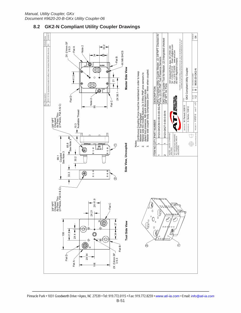
Manual, Utility Coupler, GKxDocument #9620-20-B-GKx Utility Coupler-06
Pinnacle Park • 1031 Goodworth Drive • Apex, NC 27539 • Tel: 919.772.0115 • Fax: 919.772.8259 • www.ati-ia.com • Email: [email protected] B-51
8.2 GK2-N Compliant Utility Coupler Drawings
3rd
AN
GLE
PRO
JEC
TION
33.
3
10.3
Ava
ilabl
e Th
read
99.1
Cou
pled
See
Not
e 3
30.
2
65.8
See
Not
e 3
3/8"
NP
TC
heck
edA
ir P
ass
Thru
(2 P
lace
s, F
lat A
& C
)
3/8"
NP
TC
heck
edA
ir P
ass
Thru
(2 P
lace
s, F
lat A
& C
)
21
90
41.
9
34
28
33.
2
21
2X
38.
1
2X
4mm
SF
6.3
Not
e 2
Not
e 2
4X M
6 S
HC
S
Flat
D
Flat
C
Flat
B
Flat
A
108
108
34
2X
41.
9
2X
4
2X
21
2X
4mm
SF
6.3
37
41.
9
2X
54
Flat
C
Flat
D
Flat
A
Flat
B 2 1
Not
es: Con
tinuo
us C
oupl
ing
Forc
e m
ust b
e m
aint
aine
d in
ord
er to
kee
p 1.
Mas
ter a
nd T
ool e
ngag
ed.
Mas
ter s
ide
SG
mod
els
feat
ure
2x 3
-Wire
PN
P p
rox
sens
ors
to
2.de
tect
tool
pre
senc
e, M
8 qu
ick
disc
onne
ct s
tyle
.M
aste
r sid
e co
uple
r bod
y co
mpr
esse
s 2m
m -
4mm
whe
n co
uple
d.3.
Mas
ter S
ide
View
Side
Vie
w, U
ncou
pled
Tool
Sid
e Vi
ew
Rev.
Des
crip
tion
Initi
ator
Dat
e
04EC
O 1
5118
; Upd
ated
mod
el to
refle
ct n
ew M
aste
r Sid
e BO
M st
ruct
ure
SZJ
2/2/
2017
ITE
M N
O.Q
TY.P
AR
T N
UM
BE
RD
ES
CR
IPTI
ON
11
9123
-GK
2CM
-0-0
0-0-
00-S
G-N
GK
2 C
ompl
iant
Util
ity C
oupl
er M
aste
r, (2
) 3/8
"NP
T C
heck
ed A
ir P
orts
, (2)
DC
PN
P T
ool P
rese
nce
Sen
sors
21
9123
-GK
2T-0
-00-
0-00
-NG
K2
Util
ity C
oupl
er T
ool f
or M
aste
r, (2
) Int
ergr
ated
che
cked
3/
8" N
PT
Air
Por
ts
B1:
21
3RE
VISI
ON
NO
TES:
UN
LESS
OTH
ERW
ISE
SPEC
IFIE
D.
DO
NO
T SC
ALE
DRA
WIN
G.
ALL
DIM
ENSI
ON
S A
RE IN
M
ILLIM
ETER
S.
DRA
WN
BY:
CHE
CKE
D B
Y:
M. P
erra
ult,
9/28
/12
D. N
orto
n, 1
0/8/
12
TITLE SC
ALE
SIZE
DRA
WIN
G N
UMBE
R
PRO
JEC
T #
SHEE
T
O
F 96
30-2
0-G
K2-N
1107
27-2
04
PRO
PERT
Y O
F A
TI IN
DUS
TRIA
L A
UTO
MA
TION
, IN
C. N
OT
TO B
E RE
PRO
DUC
ED IN
AN
Y M
AN
NER
EXC
EPT
ON
ORD
ER O
R W
ITH P
RIO
R W
RITT
EN A
UTHO
RIZA
TION
OF
ATI.
1031
Goo
dwor
th Dr
ive, A
pex,
NC 27
539,
USA
Tel: +
1.919
.772.0
115
Em
ail: in
fo@ati
-ia.co
mFa
x: +1
.919.7
72.82
59
www
.ati-ia
.com
ISO
9001
Reg
ister
ed C
ompa
ny
GK2
Com
plia
nt U
tility
Cou
pler

Manual, Utility Coupler, GKxDocument #9620-20-B-GKx Utility Coupler-06
Pinnacle Park • 1031 Goodworth Drive • Apex, NC 27539 • Tel: 919.772.0115 • Fax: 919.772.8259 • www.ati-ia.com • Email: [email protected] B-52
3rd
AN
GLE
PRO
JEC
TION
22
18
5
14
15
113
3
9
212
16
23
11
20
17
218
10
197
64
GK
2 C
ompl
iant
Util
ity C
oupl
er M
aste
r Ass
embl
y
Rev.
Des
crip
tion
Initi
ator
Dat
e
-Se
e Sh
eet1
--
B1:
1.5
23
REVI
SIO
N
NO
TES:
UN
LESS
OTH
ERW
ISE
SPEC
IFIE
D.
DO
NO
T SC
ALE
DRA
WIN
G.
ALL
DIM
ENSI
ON
S A
RE IN
M
ILLIM
ETER
S.
DRA
WN
BY:
CHE
CKE
D B
Y:
M. P
erra
ult,
9/28
/12
D. N
orto
n, 1
0/8/
12
TITLE SC
ALE
SIZE
DRA
WIN
G N
UMBE
R
PRO
JEC
T #
SHEE
T
O
F 96
30-2
0-G
K2-N
1107
27-2
04
PRO
PERT
Y O
F A
TI IN
DUS
TRIA
L A
UTO
MA
TION
, IN
C. N
OT
TO B
E RE
PRO
DUC
ED IN
AN
Y M
AN
NER
EXC
EPT
ON
ORD
ER O
R W
ITH P
RIO
R W
RITT
EN A
UTHO
RIZA
TION
OF
ATI.
1031
Goo
dwor
th Dr
ive, A
pex,
NC 27
539,
USA
Tel: +
1.919
.772.0
115
Em
ail: in
fo@ati
-ia.co
mFa
x: +1
.919.7
72.82
59
www
.ati-ia
.com
ISO
9001
Reg
ister
ed C
ompa
ny
GK2
Com
plia
nt U
tility
Cou
pler
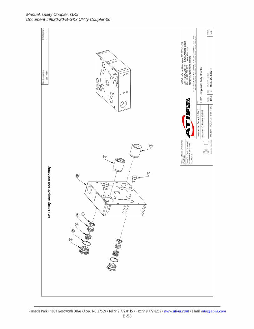
Manual, Utility Coupler, GKxDocument #9620-20-B-GKx Utility Coupler-06
Pinnacle Park • 1031 Goodworth Drive • Apex, NC 27539 • Tel: 919.772.0115 • Fax: 919.772.8259 • www.ati-ia.com • Email: [email protected] B-53
3rd
AN
GLE
PRO
JEC
TION
62
35 1
9
48
7
GK
2 U
tility
Cou
pler
Too
l Ass
embl
y
Rev.
Des
crip
tion
Initi
ator
Dat
e
-Se
e Sh
eet1
--
B1:
1.5
33
REVI
SIO
N
NO
TES:
UN
LESS
OTH
ERW
ISE
SPEC
IFIE
D.
DO
NO
T SC
ALE
DRA
WIN
G.
ALL
DIM
ENSI
ON
S A
RE IN
M
ILLIM
ETER
S.
DRA
WN
BY:
CHE
CKE
D B
Y:
M. P
erra
ult,
9/28
/12
D. N
orto
n, 1
0/8/
12
TITLE SC
ALE
SIZE
DRA
WIN
G N
UMBE
R
PRO
JEC
T #
SHEE
T
O
F 96
30-2
0-G
K2-N
1107
27-2
04
PRO
PERT
Y O
F A
TI IN
DUS
TRIA
L A
UTO
MA
TION
, IN
C. N
OT
TO B
E RE
PRO
DUC
ED IN
AN
Y M
AN
NER
EXC
EPT
ON
ORD
ER O
R W
ITH P
RIO
R W
RITT
EN A
UTHO
RIZA
TION
OF
ATI.
1031
Goo
dwor
th Dr
ive, A
pex,
NC 27
539,
USA
Tel: +
1.919
.772.0
115
Em
ail: in
fo@ati
-ia.co
mFa
x: +1
.919.7
72.82
59
www
.ati-ia
.com
ISO
9001
Reg
ister
ed C
ompa
ny
GK2
Com
plia
nt U
tility
Cou
pler

Manual, Utility Coupler, GKxDocument #9620-20-B-GKx Utility Coupler-06
Pinnacle Park • 1031 Goodworth Drive • Apex, NC 27539 • Tel: 919.772.0115 • Fax: 919.772.8259 • www.ati-ia.com • Email: [email protected] B-54
8.3 GK2-E Compliant Utility Coupler Drawings
3rd
AN
GLE
PRO
JEC
TION
2X
4mm
SF
6.4
41.
9
34
33.
2 2
8
21
2X
38.
1
90
Flat
B
Flat
A
Flat
D
Flat
C
4X M
6 S
HC
S
Not
e 2
Not
e 2
Mas
ter S
ide
View
33.
3 65
.8S
ee N
ote
3
10.3
Ava
ilabl
e Th
read
30.
2 99.1
Cou
pled
See
Not
e 3
21
Side
Vie
w, U
ncou
pled
3/8"
BS
PP
Che
cked
Air
Pas
s Th
ru(2
Pla
ces,
Fla
t A &
C)
3/8"
BS
PP
Che
cked
Air
Pas
s Th
ru(2
Pla
ces,
Fla
t A &
C)
108
108
34
41.
9
2X
21
2X
4
4X M
6x1.
0 TH
RU
6
.4
2X
41.
9
2X
54
2X
4mm
SF
8Flat
A
Flat
D
Flat
C
Flat
B
Tool
Sid
e Vi
ew
Not
es:
Con
tinuo
us C
oupl
ing
Forc
e m
ust b
e m
aint
aine
d in
ord
er to
kee
p M
aste
r and
Too
l eng
aged
.1.
Mas
ter s
ide
SG
mod
els
feat
ure
2x 3
-Wire
PN
P p
rox
sens
ors
to d
etec
t too
l pre
senc
e, M
8 qu
ick
2.di
scon
nect
sty
le.
3. M
aste
r sid
e co
uple
r bod
y co
mpr
esse
d 2m
m -
4mm
whe
n co
uple
d.
Rev.
Des
crip
tion
Initi
ator
Dat
e
04EC
O 1
5118
; Upd
ated
mod
el to
refle
ct n
ew M
aste
r Sid
e BO
M st
ruct
ure
SZJ
2/3/
2017
ITE
M N
O.Q
TYP
AR
T N
UM
BE
RD
ES
CR
IPTI
ON
11
9123
-GK
2CM
-0-0
0-0-
00-S
G-E
GK
2 C
ompl
iant
Util
ity C
oupl
er M
aste
r +/-4
mm
X-Y
, 3 D
egre
es
Ang
ular
, (2)
3/8
" BS
PP
Che
cked
Air
Por
ts, (
2) D
C P
NP
Sen
sors
21
9123
-GK
2T-0
-00-
0-00
-EG
K2
Util
ity C
oupl
er T
ool f
or M
aste
r, (2
) Int
egra
ted
Che
cked
3/8
" B
SP
P A
ir P
orts B
1:2
13
REVI
SIO
N
NO
TES:
UN
LESS
OTH
ERW
ISE
SPEC
IFIE
D.
DO
NO
T SC
ALE
DRA
WIN
G.
ALL
DIM
ENSI
ON
S A
RE IN
M
ILLIM
ETER
S.
DRA
WN
BY:
CHE
CKE
D B
Y:
M. P
erra
ult,
7/2/
12
D. N
orto
n, 1
0/12
/12
TITLE SC
ALE
SIZE
DRA
WIN
G N
UMBE
R
PRO
JEC
T #
SHEE
T
O
F 96
30-2
0-G
K2-E
------
04
PRO
PERT
Y O
F A
TI IN
DUS
TRIA
L A
UTO
MA
TION
, IN
C. N
OT
TO B
E RE
PRO
DUC
ED IN
AN
Y M
AN
NER
EXC
EPT
ON
ORD
ER O
R W
ITH P
RIO
R W
RITT
EN A
UTHO
RIZA
TION
OF
ATI.
1031
Goo
dwor
th Dr
ive, A
pex,
NC 27
539,
USA
Tel: +
1.919
.772.0
115
Em
ail: in
fo@ati
-ia.co
mFa
x: +1
.919.7
72.82
59
www
.ati-ia
.com
ISO
9001
Reg
ister
ed C
ompa
ny
GK2
Com
plia
nt U
tility
Cou
pler

Manual, Utility Coupler, GKxDocument #9620-20-B-GKx Utility Coupler-06
Pinnacle Park • 1031 Goodworth Drive • Apex, NC 27539 • Tel: 919.772.0115 • Fax: 919.772.8259 • www.ati-ia.com • Email: [email protected] B-55
3rd
AN
GLE
PRO
JEC
TION
21
18
6
7
22
1916
20
235
1
3
29
1213
4
1415
11
17
810
GK
2 C
ompl
iant
Util
ity C
oupl
er, M
aste
r Ass
embl
y, B
SPP
Rev.
Des
crip
tion
Initi
ator
Dat
e
-Se
e Sh
eet1
--
B2:
32
3RE
VISI
ON
NO
TES:
UN
LESS
OTH
ERW
ISE
SPEC
IFIE
D.
DO
NO
T SC
ALE
DRA
WIN
G.
ALL
DIM
ENSI
ON
S A
RE IN
M
ILLIM
ETER
S.
DRA
WN
BY:
CHE
CKE
D B
Y:
M. P
erra
ult,
7/2/
12
D. N
orto
n, 1
0/12
/12
TITLE SC
ALE
SIZE
DRA
WIN
G N
UMBE
R
PRO
JEC
T #
SHEE
T
O
F 96
30-2
0-G
K2-E
------
04
PRO
PERT
Y O
F A
TI IN
DUS
TRIA
L A
UTO
MA
TION
, IN
C. N
OT
TO B
E RE
PRO
DUC
ED IN
AN
Y M
AN
NER
EXC
EPT
ON
ORD
ER O
R W
ITH P
RIO
R W
RITT
EN A
UTHO
RIZA
TION
OF
ATI.
1031
Goo
dwor
th Dr
ive, A
pex,
NC 27
539,
USA
Tel: +
1.919
.772.0
115
Em
ail: in
fo@ati
-ia.co
mFa
x: +1
.919.7
72.82
59
www
.ati-ia
.com
ISO
9001
Reg
ister
ed C
ompa
ny
GK2
Com
plia
nt U
tility
Cou
pler

Manual, Utility Coupler, GKxDocument #9620-20-B-GKx Utility Coupler-06
Pinnacle Park • 1031 Goodworth Drive • Apex, NC 27539 • Tel: 919.772.0115 • Fax: 919.772.8259 • www.ati-ia.com • Email: [email protected] B-56
3rd
AN
GLE
PRO
JEC
TION
62
35
1
48
7
9
GK
2 C
ompl
iant
Util
ity C
oupl
er, T
ool A
ssem
bly,
BSP
P
Rev.
Des
crip
tion
Initi
ator
Dat
e
-Se
e Sh
eet1
--
B2:
33
3RE
VISI
ON
NO
TES:
UN
LESS
OTH
ERW
ISE
SPEC
IFIE
D.
DO
NO
T SC
ALE
DRA
WIN
G.
ALL
DIM
ENSI
ON
S A
RE IN
M
ILLIM
ETER
S.
DRA
WN
BY:
CHE
CKE
D B
Y:
M. P
erra
ult,
7/2/
12
D. N
orto
n, 1
0/12
/12
TITLE SC
ALE
SIZE
DRA
WIN
G N
UMBE
R
PRO
JEC
T #
SHEE
T
O
F 96
30-2
0-G
K2-E
------
04
PRO
PERT
Y O
F A
TI IN
DUS
TRIA
L A
UTO
MA
TION
, IN
C. N
OT
TO B
E RE
PRO
DUC
ED IN
AN
Y M
AN
NER
EXC
EPT
ON
ORD
ER O
R W
ITH P
RIO
R W
RITT
EN A
UTHO
RIZA
TION
OF
ATI.
1031
Goo
dwor
th Dr
ive, A
pex,
NC 27
539,
USA
Tel: +
1.919
.772.0
115
Em
ail: in
fo@ati
-ia.co
mFa
x: +1
.919.7
72.82
59
www
.ati-ia
.com
ISO
9001
Reg
ister
ed C
ompa
ny
GK2
Com
plia
nt U
tility
Cou
pler

Manual, Utility Coupler, GKxDocument #9620-20-B-GKx Utility Coupler-06
Pinnacle Park • 1031 Goodworth Drive • Apex, NC 27539 • Tel: 919.772.0115 • Fax: 919.772.8259 • www.ati-ia.com • Email: [email protected] B-57
8.4 GK2-R Compliant Utility Coupler Drawings
3rd
AN
GLE
PRO
JEC
TION
4X
6.8
TH
RU
10.
5 19
.7FR
OM
FA
R S
IDE
FOR
M6
SH
CS
2X
4 S
F 6.
4
2X
21
2X
41.
9
33.
2
2X
38.
1
34.
4 2
X 9
0
FLA
T A
FLA
T B
FLA
T C
FLA
T D
NO
TE 2
33.3
TOO
L
18.
4
13
4X 1
0.3
SH
CS
30.2
PIN
65.8
MA
STE
RN
OTE
3
99.1
AP
PR
OX
NO
TE 3
18.
4
16.
5
21
2X 3
/8" B
SP
TC
HE
CK
ED
AIR
PO
RTS
MA
STE
R &
TO
OL
(FLA
TS A
& C
)
108
MA
STE
R &
TO
OL
2X
21
54
2X
41.
9
37
34
2X
3.9
2X
41.
9
4X
6.8
TH
RU
11.
3 6
.4FR
OM
FA
R S
IDE
FO
R M
6 S
HC
S
FLA
T A FL
AT
B
FLA
T D
FLA
T C
2X
4 S
F 8
99.2
AP
PR
OX
NO
TE 3
65.8
MA
STE
RN
OTE
3
NO
TES
:C
ON
TIN
UO
US
CO
UP
LIN
G F
OR
CE
MU
ST
BE
MA
INTA
INE
D IN
OR
DE
R T
O K
EE
P M
AS
TER
AN
D1.
TOO
L E
NG
AG
ED
."S
E" O
N M
AS
TER
SID
E P
AR
T N
UM
BE
R D
EN
OTE
S (2
) 3-W
IRE
NP
N P
RO
X S
EN
SO
RS
TO
DE
TEC
T2.
TOO
L P
RE
SE
NC
E.
SE
NS
OR
S A
RE
M8
QU
ICK
DIS
CO
NN
EC
T S
TYLE
.M
AS
TER
SID
E C
OU
PLE
R B
OD
Y IS
CO
MP
RE
SS
ED
2M
M-4
MM
WH
EN
CO
UP
LED
.3.
TOO
L SI
DE
(PR
OJE
CTI
ON
ON
LY)
MA
STER
SID
E(P
RO
JEC
TIO
N O
NLY
)
SID
E VI
EW(U
NC
OU
PLED
)
SID
E VI
EW(C
OU
PLED
)
Rev.
Des
crip
tion
Initi
ator
Dat
e
03EC
O 1
5118
; Upd
ated
mod
el to
refle
ct n
ew M
aste
r Sid
e BO
M st
ruct
ure
SZJ
2/3/
2017
ITE
M N
O.
QTY
PA
RT
NU
MB
ER
DE
SC
RIP
TIO
N
11
9123
-GK
2CM
-0-0
0-0-
00-S
E-R
GK
2 C
ompl
iant
Util
ity C
oupl
er M
aste
r, (2
) 3/8
" BS
PT
Che
cked
Air
Por
ts, (
2)
NP
N T
ool P
rese
nce
Sen
sors
21
9123
-GK
2T-0
-00-
0-00
-RG
K2
Util
ity C
oupl
er T
ool,
(2) 3
/8" B
SP
T C
heck
ed A
ir P
orts
B2:
31
3RE
VISI
ON
NO
TES:
UN
LESS
OTH
ERW
ISE
SPEC
IFIE
D.
DO
NO
T SC
ALE
DRA
WIN
G.
ALL
DIM
ENSI
ON
S A
RE IN
M
ILLIM
ETER
S.
DRA
WN
BY:
CHE
CKE
D B
Y:
K. Z
acha
ry
10/1
2/15
M. G
ala
10/
14/1
5
TITLE SC
ALE
SIZE
DRA
WIN
G N
UMBE
R
PRO
JEC
T #
SHEE
T
O
F 96
30-2
0-G
K2-R
1507
27-1
03
PRO
PERT
Y O
F A
TI IN
DUS
TRIA
L A
UTO
MA
TION
, IN
C. N
OT
TO B
E RE
PRO
DUC
ED IN
AN
Y M
AN
NER
EXC
EPT
ON
ORD
ER O
R W
ITH P
RIO
R W
RITT
EN A
UTHO
RIZA
TION
OF
ATI.
1031
Goo
dwor
th Dr
ive, A
pex,
NC 27
539,
USA
Tel: +
1.919
.772.0
115
Em
ail: in
fo@ati
-ia.co
mFa
x: +1
.919.7
72.82
59
www
.ati-ia
.com
ISO
9001
Reg
ister
ed C
ompa
ny
GK2
-R C
ompl
iant
Util
ity C
oupl
er

Manual, Utility Coupler, GKxDocument #9620-20-B-GKx Utility Coupler-06
Pinnacle Park • 1031 Goodworth Drive • Apex, NC 27539 • Tel: 919.772.0115 • Fax: 919.772.8259 • www.ati-ia.com • Email: [email protected] B-58
3rd
AN
GLE
PRO
JEC
TION
7
9
18
16
1917
20
21
22
25
10
1314
34
51
1511
12
24
6
2
GK
2-R
CO
MPL
IAN
T U
TILI
TY C
OU
PLER
MA
STER
ASS
EMB
LYRe
v.D
escr
iptio
nIn
itiat
orD
ate
-Se
e Sh
eet1
--
B1:
22
3RE
VISI
ON
NO
TES:
UN
LESS
OTH
ERW
ISE
SPEC
IFIE
D.
DO
NO
T SC
ALE
DRA
WIN
G.
ALL
DIM
ENSI
ON
S A
RE IN
M
ILLIM
ETER
S.
DRA
WN
BY:
CHE
CKE
D B
Y:
K. Z
acha
ry
10/1
2/15
M. G
ala
10/
14/1
5
TITLE SC
ALE
SIZE
DRA
WIN
G N
UMBE
R
PRO
JEC
T #
SHEE
T
O
F 96
30-2
0-G
K2-R
1507
27-1
03
PRO
PERT
Y O
F A
TI IN
DUS
TRIA
L A
UTO
MA
TION
, IN
C. N
OT
TO B
E RE
PRO
DUC
ED IN
AN
Y M
AN
NER
EXC
EPT
ON
ORD
ER O
R W
ITH P
RIO
R W
RITT
EN A
UTHO
RIZA
TION
OF
ATI.
1031
Goo
dwor
th Dr
ive, A
pex,
NC 27
539,
USA
Tel: +
1.919
.772.0
115
Em
ail: in
fo@ati
-ia.co
mFa
x: +1
.919.7
72.82
59
www
.ati-ia
.com
ISO
9001
Reg
ister
ed C
ompa
ny
GK2
-R C
ompl
iant
Util
ity C
oupl
er
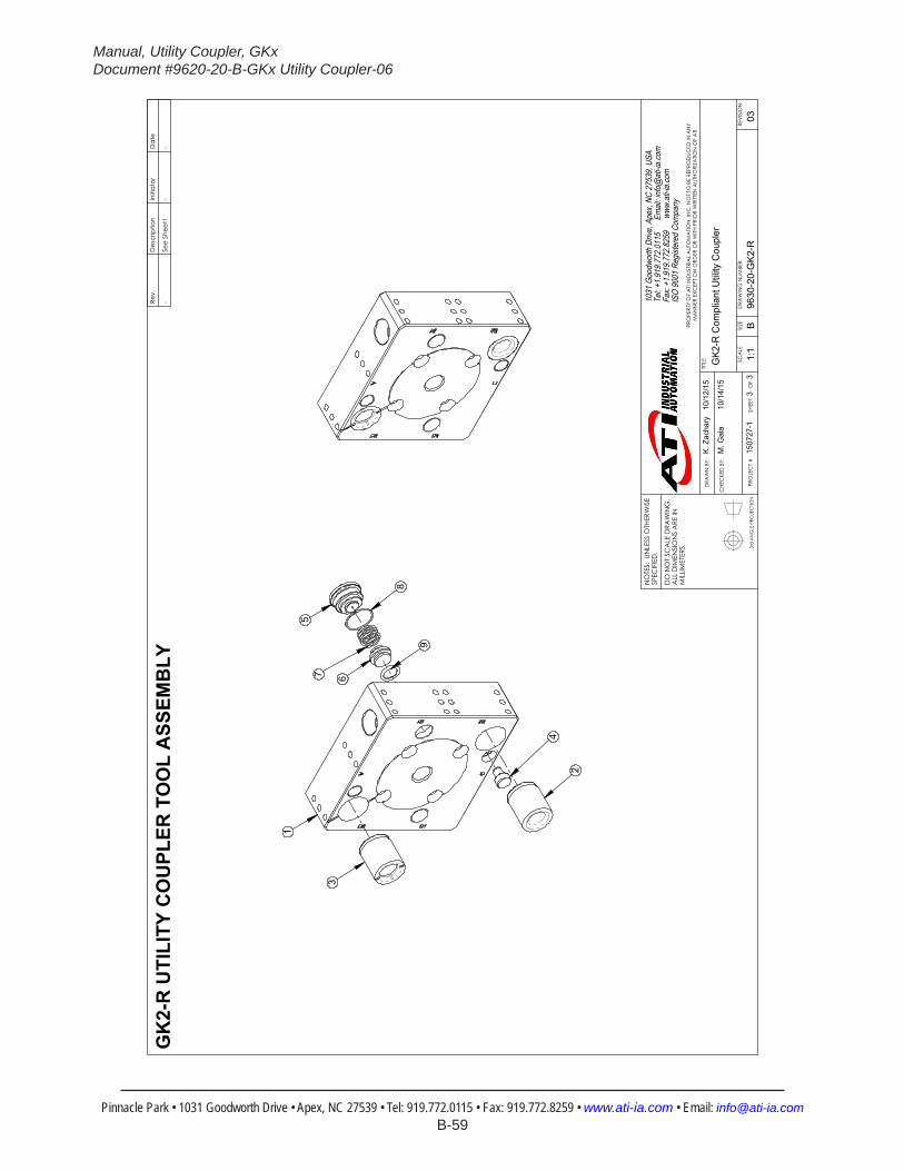
Manual, Utility Coupler, GKxDocument #9620-20-B-GKx Utility Coupler-06
Pinnacle Park • 1031 Goodworth Drive • Apex, NC 27539 • Tel: 919.772.0115 • Fax: 919.772.8259 • www.ati-ia.com • Email: [email protected] B-59
3rd
AN
GLE
PRO
JEC
TION
2
4
1
3
9
67
8
5
GK
2-R
UTI
LITY
CO
UPL
ER T
OO
L A
SSEM
BLY
Rev.
Des
crip
tion
Initi
ator
Dat
e
-Se
e Sh
eet1
--
B1:
13
3RE
VISI
ON
NO
TES:
UN
LESS
OTH
ERW
ISE
SPEC
IFIE
D.
DO
NO
T SC
ALE
DRA
WIN
G.
ALL
DIM
ENSI
ON
S A
RE IN
M
ILLIM
ETER
S.
DRA
WN
BY:
CHE
CKE
D B
Y:
K. Z
acha
ry
10/1
2/15
M. G
ala
10/
14/1
5
TITLE SC
ALE
SIZE
DRA
WIN
G N
UMBE
R
PRO
JEC
T #
SHEE
T
O
F 96
30-2
0-G
K2-R
1507
27-1
03
PRO
PERT
Y O
F A
TI IN
DUS
TRIA
L A
UTO
MA
TION
, IN
C. N
OT
TO B
E RE
PRO
DUC
ED IN
AN
Y M
AN
NER
EXC
EPT
ON
ORD
ER O
R W
ITH P
RIO
R W
RITT
EN A
UTHO
RIZA
TION
OF
ATI.
1031
Goo
dwor
th Dr
ive, A
pex,
NC 27
539,
USA
Tel: +
1.919
.772.0
115
Em
ail: in
fo@ati
-ia.co
mFa
x: +1
.919.7
72.82
59
www
.ati-ia
.com
ISO
9001
Reg
ister
ed C
ompa
ny
GK2
-R C
ompl
iant
Util
ity C
oupl
er
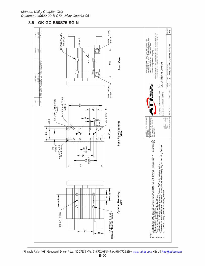
Manual, Utility Coupler, GKxDocument #9620-20-B-GKx Utility Coupler-06
Pinnacle Park • 1031 Goodworth Drive • Apex, NC 27539 • Tel: 919.772.0115 • Fax: 919.772.8259 • www.ati-ia.com • Email: [email protected] B-60
8.5 GK-GC-B50S75-SG-N
3rd
AN
GLE
PRO
JEC
TION
21N
ote
5
41.9
Not
e 4
90N
ote
4
28
34
4
8X M
6X1.
0 Th
ru P
late
Not
e 5
2X4m
m S
F 6
.5N
ote
5
146
60
40
130
6
6
2X
5
H7
8
41.
9
4X M
10 X
1.5
Thru
Pla
te
119
4X
8.6
Thru
For
M8
SH
CS
Flow
Con
trol,
1/4
NP
TFl
ow C
ontro
l, 1/
4 N
PT
Not
e 3
48
66
41
48
24
2X
5
H7
8
4X M
10 X
1.5
20
Opt
iona
l Mou
ntin
g Fe
atur
e
Not
es: Uni
t fea
ture
s S
MC
Gui
ded
Cyl
inde
r (M
GP
M50
TN-7
5Z-M
9PS
AP
CS
) with
cus
tom
ATI
mou
ntin
g 1.
patte
rn a
dded
to to
ol p
late
.R
ecom
men
ded
usab
le s
troke
is 5
0mm
.2.
Uni
t fea
ture
s 1
cylin
der p
ositi
on s
enso
r, 3-
wire
PN
P w
ith M
8 co
nnec
tor.
3.C
usto
mer
mus
t con
side
r pus
h fo
rces
of d
rive
cylin
der w
hen
desi
gnin
g su
rrou
ndin
g fix
ture
s.4.
ATI
cus
tom
Util
ity C
oupl
er m
ount
ing
feat
ure
5.
Push
Pla
te M
ount
ing
View
Cyl
inde
r Mou
ntin
g Vi
ewFr
ont V
iew
02
Rev.
Des
crip
tion
Initi
ator
Dat
e
01In
itial
Dra
win
gD
AN
12/1
1/12
02EC
O 1
3906
: Upd
ated
371
0-20
-340
0 m
odel
to c
urre
nt
SMC
revi
sion,
ad
ded
full S
MC
par
t num
ber i
n no
tes.
DJB
10/2
9/20
15
B1:
21
1RE
VISI
ON
NO
TES:
UN
LESS
OTH
ERW
ISE
SPEC
IFIE
D.
DO
NO
T SC
ALE
DRA
WIN
G.
ALL
DIM
ENSI
ON
S A
RE IN
M
ILLIM
ETER
S.
DRA
WN
BY:
CHE
CKE
D B
Y:
Dan
Nor
ton
12/1
1/12
M. P
erra
ult 1
2/11
/12
TITLE SC
ALE
SIZE
DRA
WIN
G N
UMBE
R
PRO
JEC
T #
SHEE
T
O
F 96
30-2
0-G
K-G
C-B
50S7
5-SG
-N-
02
PRO
PERT
Y O
F A
TI IN
DUS
TRIA
L A
UTO
MA
TION
, IN
C. N
OT
TO B
E RE
PRO
DUC
ED IN
AN
Y M
AN
NER
EXC
EPT
ON
ORD
ER O
R W
ITH P
RIO
R W
RITT
EN A
UTHO
RIZA
TION
OF
ATI.
1031
Goo
dwor
th Dr
ive, A
pex,
NC 27
539,
USA
Tel: +
1.919
.772.0
115
Em
ail: in
fo@ati
-ia.co
mFa
x: +1
.919.7
72.82
59
www
.ati-ia
.com
ISO
9001
Reg
ister
ed C
ompa
ny
GK-
GC
-B50
S75
Driv
e U
nit

Manual, Utility Coupler, GKxDocument #9620-20-B-GKx Utility Coupler-06
Pinnacle Park • 1031 Goodworth Drive • Apex, NC 27539 • Tel: 919.772.0115 • Fax: 919.772.8259 • www.ati-ia.com • Email: [email protected] B-61
8.6 GK-GC-B63S50Z1-SG-N
3rd
AN
GLE
PRO
JEC
TION
2X 4
1.9
Not
e 4
80
34
2X 9
0N
ote
4
2X 28
2X
4
2X
4.05
94.
034 S
F 7
.6N
ote
4
8X M
6X1.
0 Th
ru P
late
Not
e 4
2X
5 H
7 8
35.
4
104
.9
23
4X 2
1N
ote
4
70 P
ush
Pla
te
4X 4
1.9
Not
e 4
4
35
108
2X 130
2X
50
Push
Pla
teM
ount
ing
View
4X M
10 S
HC
S(M
10 X
1.5
Thr
u P
late
)
52
80
245
1
62
41
50
26
2X
5 H
7 8
4X M
10 X
1.5
2
0O
ptio
nal M
ount
ing
Feat
ure
Cyl
inde
r Mou
ntin
g Vi
ew
Spr
ing-
Ret
urn
Har
dwar
eN
ote
1, 6
99
4X
8.6
Thru
for M
8 S
HC
S
23
28
+ S
troke
12 Pla
te
Fron
t Vie
w
Not
e 2
2X F
low
Con
trol,
1/4
NP
T
Exh
aust
Muf
fler
Not
e 6
Not
es:
Uni
t fea
ture
s S
MC
Gui
ded
Cyl
inde
r (M
GP
M63
TN-5
0Z-M
9PS
AP
CS
) with
cus
tom
ATI
mou
ntin
g 1.
patte
rns
adde
d to
tool
pla
te a
nd b
ody,
and
cus
tom
spr
ing-
retu
rn h
ardw
are
adde
d.U
nit f
eatu
res
SM
C G
uide
d C
ylin
der M
GP
M S
erie
s, 6
3mm
bor
e, 5
0mm
max
stro
ke.
2.R
ecom
men
ded
usab
le s
troke
is 4
0mm
.U
nit f
eatu
res
1 cy
linde
r pos
ition
sen
sor,
3-w
ire P
NP
with
M8
conn
ecto
r.3.
Cus
tom
er m
ust c
onsi
der p
ush
forc
es o
f driv
e cy
linde
r whe
n de
sign
ing
surr
ound
ing
fixtu
res.
4.A
TI c
usto
m U
tility
Cou
pler
mou
ntin
g fe
atur
e.5.
If de
sire
d, s
prin
g-re
turn
har
dwar
e an
d ex
haus
t muf
fler m
ay b
e re
mov
ed w
ithou
t con
sequ
ence
and
6.
the
cylin
der c
an o
pera
te in
sta
ndar
d do
uble
-act
ing
fash
ion.
Rev.
Des
crip
tion
Initi
ator
Dat
e
01In
itial
Dra
win
gBV
K2/
17/2
016
B1:
21
2RE
VISI
ON
NO
TES:
UN
LESS
OTH
ERW
ISE
SPEC
IFIE
D.
DO
NO
T SC
ALE
DRA
WIN
G.
ALL
DIM
ENSI
ON
S A
RE IN
M
ILLIM
ETER
S.
DRA
WN
BY:
CHE
CKE
D B
Y:
B. K
endr
ick
2/17
/16
D. N
orto
n 2/
17/1
6
TITLE SC
ALE
SIZE
DRA
WIN
G N
UMBE
R
PRO
JEC
T #
SHEE
T
O
F 96
30-2
0-G
K-G
C-B
63S5
0Z1-
SG-N
1601
04-1
01
PRO
PERT
Y O
F A
TI IN
DUS
TRIA
L A
UTO
MA
TION
, IN
C. N
OT
TO B
E RE
PRO
DUC
ED IN
AN
Y M
AN
NER
EXC
EPT
ON
ORD
ER O
R W
ITH P
RIO
R W
RITT
EN A
UTHO
RIZA
TION
OF
ATI.
1031
Goo
dwor
th Dr
ive, A
pex,
NC 27
539,
USA
Tel: +
1.919
.772.0
115
Em
ail: in
fo@ati
-ia.co
mFa
x: +1
.919.7
72.82
59
www
.ati-ia
.com
ISO
9001
Reg
ister
ed C
ompa
ny
GK-
GC
-B63
S50Z
1 D
rive
Uni
t

Manual, Utility Coupler, GKxDocument #9620-20-B-GKx Utility Coupler-06
Pinnacle Park • 1031 Goodworth Drive • Apex, NC 27539 • Tel: 919.772.0115 • Fax: 919.772.8259 • www.ati-ia.com • Email: [email protected] B-62
3rd
AN
GLE
PRO
JEC
TION
712
11
8
13
14
9
6
5
10
1
GK
Spr
ing-
Ret
urn
Gui
de C
ylin
der A
ssem
bly
Rev.
Des
crip
tion
Initi
ator
Dat
e
-Se
e Sh
eet1
--
B1:
32
2RE
VISI
ON
NO
TES:
UN
LESS
OTH
ERW
ISE
SPEC
IFIE
D.
DO
NO
T SC
ALE
DRA
WIN
G.
ALL
DIM
ENSI
ON
S A
RE IN
M
ILLIM
ETER
S.
DRA
WN
BY:
CHE
CKE
D B
Y:
B. K
endr
ick
2/17
/16
D. N
orto
n 2/
17/1
6
TITLE SC
ALE
SIZE
DRA
WIN
G N
UMBE
R
PRO
JEC
T #
SHEE
T
O
F 96
30-2
0-G
K-G
C-B
63S5
0Z1-
SG-N
1601
04-1
01
PRO
PERT
Y O
F A
TI IN
DUS
TRIA
L A
UTO
MA
TION
, IN
C. N
OT
TO B
E RE
PRO
DUC
ED IN
AN
Y M
AN
NER
EXC
EPT
ON
ORD
ER O
R W
ITH P
RIO
R W
RITT
EN A
UTHO
RIZA
TION
OF
ATI.
1031
Goo
dwor
th Dr
ive, A
pex,
NC 27
539,
USA
Tel: +
1.919
.772.0
115
Em
ail: in
fo@ati
-ia.co
mFa
x: +1
.919.7
72.82
59
www
.ati-ia
.com
ISO
9001
Reg
ister
ed C
ompa
ny
GK-
GC
-B63
S50Z
1 D
rive
Uni
t

Manual, Utility Coupler, GKxDocument #9620-20-B-GKx Utility Coupler-06
Pinnacle Park • 1031 Goodworth Drive • Apex, NC 27539 • Tel: 919.772.0115 • Fax: 919.772.8259 • www.ati-ia.com • Email: [email protected] B-63
8.7 GK-GC-B63S75-SG-N
3rd
AN
GLE
PRO
JEC
TION
34
41.
9 9
0 1
30
4
21 5
0
41.
9
70
158
80
8X M
6X1.
0 Th
ru
2X4m
m S
F6.
5N
ote
5
2X5H
78
28
4x M
10 x
1.5
Thru
Pla
te
124
8.6
Thru
For M
8 S
HC
S4
Pla
ces
Flow
Con
trol,
1/4
NP
TFl
ow C
ontro
l, 1/
4 N
PT
Not
e 3
4X M
10 x
1.5
20
Opt
iona
l Mou
ntin
g Fe
atur
e
80
41
26
52
50
2X
5 H
78
Not
es: Uni
t fea
ture
s S
MC
Gui
ded
Cyl
inde
r (M
GP
M63
TN-7
5Z-M
9PS
AP
CS
) with
cus
tom
ATI
mou
ntin
g 1.
patte
rn a
dded
to to
ol p
late
.U
nit f
eatu
res
SM
C G
uide
d C
ylin
der M
GP
M S
erie
s, 6
3mm
bor
e, 7
5mm
max
stro
ke.
2.R
ecom
men
ded
usab
le s
troke
is 5
0mm
.U
nit f
eatu
res
1 cy
linde
r pos
ition
sen
sor,
3-w
ire P
NP
with
M8
conn
ecto
r.3.
Cus
tom
er m
ust c
onsi
der p
ush
forc
es o
f driv
e cy
linde
r whe
n de
sign
ing
surr
ound
ing
fixtu
res.
4.A
TI c
usto
m U
tility
Cou
pler
mou
ntin
g fe
atur
e5.
Fron
t Vie
wPu
sh P
late
Mou
ntin
g Vi
ewC
ylin
der M
ount
ing
View
03
Rev.
Des
crip
tion
Initi
ator
Dat
e
02Ec
o 10
257;
Rel
ease
DA
N12
/11/
12
03EC
O 1
3906
: Upd
ated
371
0-20
-340
1 m
odel
to c
urre
nt
SMC
revi
sion,
ad
ded
full S
MC
par
t num
ber i
n no
tes.
DJB
10/2
9/20
15
B1:
21
1RE
VISI
ON
NO
TES:
UN
LESS
OTH
ERW
ISE
SPEC
IFIE
D.
DO
NO
T SC
ALE
DRA
WIN
G.
ALL
DIM
ENSI
ON
S A
RE IN
M
ILLIM
ETER
S.
DRA
WN
BY:
CHE
CKE
D B
Y:
Dan
Nor
ton,
12/
11/1
2
Kyle
Zac
hary
, 11/
7/12
TITLE SC
ALE
SIZE
DRA
WIN
G N
UMBE
R
PRO
JEC
T #
SHEE
T
O
F 96
30-2
0-G
K-G
C-B
63S7
5-SG
-N---
------
----
03
PRO
PERT
Y O
F A
TI IN
DUS
TRIA
L A
UTO
MA
TION
, IN
C. N
OT
TO B
E RE
PRO
DUC
ED IN
AN
Y M
AN
NER
EXC
EPT
ON
ORD
ER O
R W
ITH P
RIO
R W
RITT
EN A
UTHO
RIZA
TION
OF
ATI.
1031
Goo
dwor
th Dr
ive, A
pex,
NC 27
539,
USA
Tel: +
1.919
.772.0
115
Em
ail: in
fo@ati
-ia.co
mFa
x: +1
.919.7
72.82
59
www
.ati-ia
.com
ISO
9001
Reg
ister
ed C
ompa
ny
GK-
GC
-B63
S75
Driv
e U
nit

Manual, Utility Coupler, GKxDocument #9620-20-B-GKx Utility Coupler-06
Pinnacle Park • 1031 Goodworth Drive • Apex, NC 27539 • Tel: 919.772.0115 • Fax: 919.772.8259 • www.ati-ia.com • Email: [email protected] B-64
8.8 GK-GCE2-PM24600-B-SG
3rd
AN
GLE
PRO
JEC
TION
352
Ret
ract
ed
Pro
x S
enso
r Bra
cket
is R
emov
able
and
ca
n be
relo
cate
d on
eith
er s
ide
of
actu
ator
, in
eith
er to
p or
bot
tom
pos
ition
.
3 W
ire D
C P
rox
Sen
sor
PN
P M
8 Q
uick
Con
nect
38.
1
19.
1
86.
5
2X
15.
9
9.5
2
10.3
2X
6.4
9.5
Bra
ke L
ead
Wire
s22
AW
G, 1
2" W
hite
2X .1
87" M
ale
Fast
on
4X M
6 x1
.0
12.7
118
.7
130
.5
2X
63.
5 2
X 1
9.1
3X
114
.3
2X
50.
8
9.5
12.7
4X
6.76
Thr
u11
.1 x
7.1
M8
x 1.
25 O
ppos
ite S
ide
2X
10.
2 2
X 7
.6
2X
14.
6
2X
5.8
2X
41.
9 2
X 4
7
2X
72.
4 2X
90
8X M
6X1.
0 Th
ru
Rev.
Des
crip
tion
Initi
ator
Dat
e
02Ec
o 10
257;
Rel
ease
DA
N11
/7/2
012
Mot
or C
hara
cter
istic
sR
ated
Vol
tage
DC
24V
olts
Rat
ed C
urre
nt6.
1A
mps
Rat
ed P
ower
Out
145
Wat
tsN
o Lo
ad C
urre
nt.8
6A
mps
Rat
ed T
orqu
e40
oz-in
Bra
ke D
ata
Torq
ue3
lb-in
Rat
ed V
olta
ge D
C24
Vol
tsR
ated
Cur
rent
.19
Am
ps
B1:
31
2RE
VISI
ON
NO
TES:
UN
LESS
OTH
ERW
ISE
SPEC
IFIE
D.
DO
NO
T SC
ALE
DRA
WIN
G.
ALL
DIM
ENSI
ON
S A
RE IN
M
ILLIM
ETER
S.
DRA
WN
BY:
CHE
CKE
D B
Y:
Dan
Nor
ton,
11/
7/12
Kyle
Zac
hary
, 11/
7/12
TITLE SC
ALE
SIZE
DRA
WIN
G N
UMBE
R
PRO
JEC
T #
SHEE
T
O
F 96
30-2
0-G
K-G
CE2
-PM
2460
0-B-
SG-
02
PRO
PERT
Y O
F A
TI IN
DUS
TRIA
L A
UTO
MA
TION
, IN
C. N
OT
TO B
E RE
PRO
DUC
ED IN
AN
Y M
AN
NER
EXC
EPT
ON
ORD
ER O
R W
ITH P
RIO
R W
RITT
EN A
UTHO
RIZA
TION
OF
ATI.
1031
Goo
dwor
th Dr
ive, A
pex,
NC 27
539,
USA
Tel: +
1.919
.772.0
115
Em
ail: in
fo@ati
-ia.co
mFa
x: +1
.919.7
72.82
59
www
.ati-ia
.com
ISO
9001
Reg
ister
ed C
ompa
ny
GK-
GC
E2 D
rive
Uni
t

Manual, Utility Coupler, GKxDocument #9620-20-B-GKx Utility Coupler-06
Pinnacle Park • 1031 Goodworth Drive • Apex, NC 27539 • Tel: 919.772.0115 • Fax: 919.772.8259 • www.ati-ia.com • Email: [email protected] B-65
3rd
AN
GLE
PRO
JEC
TION
3
4
1
212
5
7
GK
-GC
E2 E
lect
ric D
rive
Uni
t Ass
embl
y
Rev.
Des
crip
tion
Initi
ator
Dat
e
-Se
e Sh
eet1
--
B1:
22
2RE
VISI
ON
NO
TES:
UN
LESS
OTH
ERW
ISE
SPEC
IFIE
D.
DO
NO
T SC
ALE
DRA
WIN
G.
ALL
DIM
ENSI
ON
S A
RE IN
M
ILLIM
ETER
S.
DRA
WN
BY:
CHE
CKE
D B
Y:
Dan
Nor
ton,
11/
7/12
Kyle
Zac
hary
, 11/
7/12
TITLE SC
ALE
SIZE
DRA
WIN
G N
UMBE
R
PRO
JEC
T #
SHEE
T
O
F 96
30-2
0-G
K-G
CE2
-PM
2460
0-B-
SG-
02
PRO
PERT
Y O
F A
TI IN
DUS
TRIA
L A
UTO
MA
TION
, IN
C. N
OT
TO B
E RE
PRO
DUC
ED IN
AN
Y M
AN
NER
EXC
EPT
ON
ORD
ER O
R W
ITH P
RIO
R W
RITT
EN A
UTHO
RIZA
TION
OF
ATI.
1031
Goo
dwor
th Dr
ive, A
pex,
NC 27
539,
USA
Tel: +
1.919
.772.0
115
Em
ail: in
fo@ati
-ia.co
mFa
x: +1
.919.7
72.82
59
www
.ati-ia
.com
ISO
9001
Reg
ister
ed C
ompa
ny
GK-
GC
E2 D
rive
Uni
t

Manual, Utility Coupler, GKxDocument #9620-20-B-GKx Utility Coupler-06
Pinnacle Park • 1031 Goodworth Drive • Apex, NC 27539 • Tel: 919.772.0115 • Fax: 919.772.8259 • www.ati-ia.com • Email: [email protected] B-66
8.9 GK-GCE-PM24400-B-SG
3rd
AN
GLE
PRO
JEC
TION
301.
3R
etra
cted
Pro
x S
enso
r Bra
cket
is R
emov
able
and
ca
n be
relo
cate
d on
eith
er s
ide
of
actu
ator
, in
eith
er to
p or
bot
tom
pos
ition
.
3 W
ire D
C P
rox
Sen
sor
PN
P M
8 Q
uick
Con
nect
210
.3
38.
1 1
9.1
86.
5
9.5
15.
9 6.
49.
5
Bra
ke L
ead
Wire
s22
AW
G, 1
2" W
hite
2X .1
87" M
ale
Fast
on
4X M
6 x1
.0
12.7
117
.5
130
.5
2X
19.
1 2
X 6
3.5
2X
114
.3
2X
50.
8
9.5
12.7
4X
6.76
Thr
u11
.1 x
7.1
M8
x 1.
25 O
ppos
ite S
ide
4X M
6X1.
0 Th
ru 2X
72.
4 2X
90
2X
47
2X
41.
9
2X
10.
2 2
X 7
.6
2X
5.8
2
X 1
4.6
Rev.
Des
crip
tion
Initi
ator
Dat
e
02Ec
o 10
257;
Rel
ease
DA
N11
/7/2
012
Mot
or C
hara
cter
istic
sR
ated
Vol
tage
DC
24V
olts
Rat
ed C
urre
nt6.
1A
mps
Rat
ed P
ower
Out
145
Wat
tsN
o Lo
ad C
urre
nt.8
6A
mps
Rat
ed T
orqu
e40
oz-in
Bra
ke D
ata
Torq
ue3
lb-in
Rat
ed V
olta
ge D
C24
Vol
tsR
ated
Cur
rent
.19
Am
ps
B1:
31
2RE
VISI
ON
NO
TES:
UN
LESS
OTH
ERW
ISE
SPEC
IFIE
D.
DO
NO
T SC
ALE
DRA
WIN
G.
ALL
DIM
ENSI
ON
S A
RE IN
M
ILLIM
ETER
S.
DRA
WN
BY:
CHE
CKE
D B
Y:
Dan
Nor
ton,
11/
7/12
Kyle
Zac
hary
, 11/
7/12
TITLE SC
ALE
SIZE
DRA
WIN
G N
UMBE
R
PRO
JEC
T #
SHEE
T
O
F 96
30-2
0-G
K-G
CE-
PM24
400-
B-SG
-02
PRO
PERT
Y O
F A
TI IN
DUS
TRIA
L A
UTO
MA
TION
, IN
C. N
OT
TO B
E RE
PRO
DUC
ED IN
AN
Y M
AN
NER
EXC
EPT
ON
ORD
ER O
R W
ITH P
RIO
R W
RITT
EN A
UTHO
RIZA
TION
OF
ATI.
1031
Goo
dwor
th Dr
ive, A
pex,
NC 27
539,
USA
Tel: +
1.919
.772.0
115
Em
ail: in
fo@ati
-ia.co
mFa
x: +1
.919.7
72.82
59
www
.ati-ia
.com
ISO
9001
Reg
ister
ed C
ompa
ny
GK-
GC
E D
rive
Uni
t
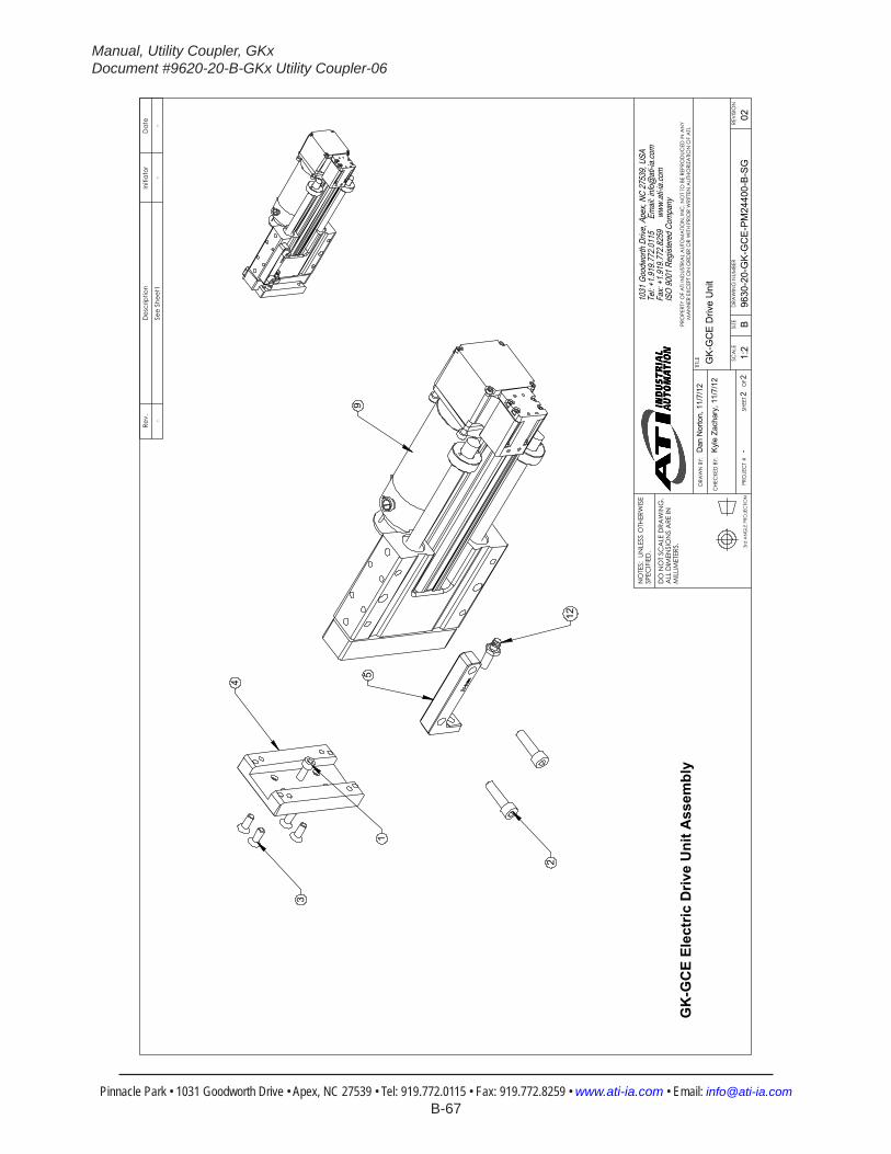
Manual, Utility Coupler, GKxDocument #9620-20-B-GKx Utility Coupler-06
Pinnacle Park • 1031 Goodworth Drive • Apex, NC 27539 • Tel: 919.772.0115 • Fax: 919.772.8259 • www.ati-ia.com • Email: [email protected] B-67
3rd
AN
GLE
PRO
JEC
TION
3
4
1
2
12
59
GK
-GC
E El
ectr
ic D
rive
Uni
t Ass
embl
y
Rev.
Des
crip
tion
Initi
ator
Dat
e
-Se
e Sh
eet1
--
B1:
22
2RE
VISI
ON
NO
TES:
UN
LESS
OTH
ERW
ISE
SPEC
IFIE
D.
DO
NO
T SC
ALE
DRA
WIN
G.
ALL
DIM
ENSI
ON
S A
RE IN
M
ILLIM
ETER
S.
DRA
WN
BY:
CHE
CKE
D B
Y:
Dan
Nor
ton,
11/
7/12
Kyle
Zac
hary
, 11/
7/12
TITLE SC
ALE
SIZE
DRA
WIN
G N
UMBE
R
PRO
JEC
T #
SHEE
T
O
F 96
30-2
0-G
K-G
CE-
PM24
400-
B-SG
-02
PRO
PERT
Y O
F A
TI IN
DUS
TRIA
L A
UTO
MA
TION
, IN
C. N
OT
TO B
E RE
PRO
DUC
ED IN
AN
Y M
AN
NER
EXC
EPT
ON
ORD
ER O
R W
ITH P
RIO
R W
RITT
EN A
UTHO
RIZA
TION
OF
ATI.
1031
Goo
dwor
th Dr
ive, A
pex,
NC 27
539,
USA
Tel: +
1.919
.772.0
115
Em
ail: in
fo@ati
-ia.co
mFa
x: +1
.919.7
72.82
59
www
.ati-ia
.com
ISO
9001
Reg
ister
ed C
ompa
ny
GK-
GC
E D
rive
Uni
t