MANUAL TLV25 KV40 KV80 - Tamson Instruments …An illuminator providing diffused fluorescent light...
26
Tamson Instruments bv, van 't Hoffstraat 12, 2665 JL Bleiswijk, Netherlands . +31(0)10 – 522 43 73 Fax. +31(0)10 – 521 19 41 \\word\manuals\tlv25\\mantlv25.doc Date 09-2010 Rev. 1.31 UK pag. 1 / 26 MANUAL TLV25 KV40 KV80
Transcript of MANUAL TLV25 KV40 KV80 - Tamson Instruments …An illuminator providing diffused fluorescent light...

Tamson Instruments bv, van 't Hoffstraat 12, 2665 JL Bleiswijk, Netherlands �. +31(0)10 – 522 43 73 Fax. +31(0)10 – 521 19 41
\\word\manuals\tlv25\\mantlv25.doc Date 09-2010 Rev. 1.31 UK pag. 1 / 26
MANUAL
TLV25
KV40
KV80

Tamson Instruments bv, van 't Hoffstraat 12, 2665 JL Bleiswijk, Netherlands �. +31(0)10 – 522 43 73 Fax. +31(0)10 – 521 19 41
\\word\manuals\tlv25\\mantlv25.doc Date 09-2010 Rev. 1.31 UK pag. 2 / 26
Safety and Warnings Make sure you read and understand all instructions and safety precautions listed in this manual, before installing or operating the equipment. If there are any questions concerning the operation of the equipment or about the information in this manual please contact your local dealer or our sales department first. Performance of installation, operation or maintenance other than those described in this manual may result in a hazardous situation and may void the manufacturers warranty. Never operate equipment that is not correctly installed. Unqualified personnel must not operate the equipment. Avoid damage to the equipment, or its accessories, caused by incorrect operation. Important: - When performing service, maintenance or moving the apparatus, always disconnect the line cord of
the apparatus, - Proper skilled and trained personel is only allowed to operate this equipment, - Take notice of warning labels and do not remove them, - Refer service and repairs to qualified technician, - If a problem persists, call your supplier or Tamson Instruments bv
Warranty
Tamson Instruments bv warrants that all equipment manufactured by it shall be free from defects in material and workmanship, which might impair its usefulness. Tamson Instruments bv. does not warranty that the equipment is fit for any particular use. The manufacturer is only responsible for the security, reliability and performance of the equipment, if the unit is operated in accordance with the operating instructions, extensions, adjustments, and when changes or repair is performed by Tamson Instruments bv or authorized persons only. This warranty is limited to one year from date of invoicing. All equipment and materials are further subject to tolerances and variations consistent with the usage of the trade.

Tamson Instruments bv, van 't Hoffstraat 12, 2665 JL Bleiswijk, Netherlands �. +31(0)10 – 522 43 73 Fax. +31(0)10 – 521 19 41
\\word\manuals\tlv25\\mantlv25.doc Date 09-2010 Rev. 1.31 UK pag. 3 / 26
Contents
SAFETY AND WARNINGS.......................................................................................2
Warranty .................................................................................................................................................. 2
VISCOMETER BATH TLV25 ....................................................................................5
EC declaration of conformity TLV25......................................................................................................... 5
Delivery checklist ..................................................................................................................................... 6
The TLV25, general ................................................................................................................................. 7
Installation ............................................................................................................................................... 8
Filling and Bath liquids ............................................................................................................................. 8
Cooling .................................................................................................................................................... 9
Heating .................................................................................................................................................... 9
Operating the controller ........................................................................................................................... 9
Operation .......................................................................................................................................... 10
Quick start ......................................................................................................................................... 10
What is tuning ................................................................................................................................... 11
Automatic tuning................................................................................................................................ 12
Manual tuning.................................................................................................................................... 13
Manual tuning by Ziegler-Nichols ...................................................................................................... 13
Setting the cutback values................................................................................................................. 14
Faultfinding ............................................................................................................................................ 15
Technical Specs TLV25 ......................................................................................................................... 16
Spare part list TLV25 ............................................................................................................................. 17
Part number ........................................................................................................................................... 17
115 Volts................................................................................................................................................ 17
CRYOSTAT KV-SERIES ........................................................................................18
EC declaration of conformity cryostat..................................................................................................... 18
Cryostat, Installation and use................................................................................................................. 19
Cryostat fails to operate ......................................................................................................................... 19
KV40 Cryostat........................................................................................................................................ 20
Technical Specs KV40 ...................................................................................................................... 21
Using the KV for other cooling purposes ........................................................................................... 21
Ordering codes KV40 ........................................................................................................................ 22
Spare part list KV40 .......................................................................................................................... 22
Part numbers ......................................................................................................................................... 22
Principal diagram KV40..................................................................................................................... 22
KV80 Cryostat........................................................................................................................................ 22
KV80 Cryostat........................................................................................................................................ 23
Technical Specs KV80 ...................................................................................................................... 23
Using the KV for other cooling purposes ........................................................................................... 23
Ordering codes KV80 ........................................................................................................................ 24
Spare part list KV80 .......................................................................................................................... 25
Part numbers ......................................................................................................................................... 25
Principal diagram KV80..................................................................................................................... 26
DISCLAIMER..........................................................................................................26

Tamson Instruments bv, van 't Hoffstraat 12, 2665 JL Bleiswijk, Netherlands �. +31(0)10 – 522 43 73 Fax. +31(0)10 – 521 19 41
\\word\manuals\tlv25\\mantlv25.doc Date 09-2010 Rev. 1.31 UK pag. 4 / 26
Tamson Instruments bv van 't Hoffstraat 12 2665 JL BLEISWIJK The Netherlands We wish to thank you for the purchase of this Tamson Thermostatic Bath. You have bought an instrument with the latest technology. For a fast settlement of the one-year warranty, please return this warranty certificate as soon as possible to the following fax number +31 10 521 19 41 or the above mentioned address. Model Thermostatic bath : …………………………………………………………. Name of your company : …………………………………………………………. Name of user : …………………………………………………………. Address : …………………………………………………………. ……….…………………………………………………. ……….…………………………………………………. ……….…………………………………………………. Tel. nr. : ……….…………………………………………………. Serial number : ………………………………. Mains voltage: …………….. Mains Freq.: …………………Hz Date of delivery : …………….. Name of dealer: ……….………………………………………………….
……….…………………………………………………. ………………………………….………………………. Signature: …...………………………

Tamson Instruments bv, van 't Hoffstraat 12, 2665 JL Bleiswijk, Netherlands �. +31(0)10 – 522 43 73 Fax. +31(0)10 – 521 19 41
\\word\manuals\tlv25\\mantlv25.doc Date 09-2010 Rev. 1.31 UK pag. 5 / 26
Viscometer bath TLV25
EC declaration of conformity TLV25
Manufacturer: Tamson Instruments bv van 't Hoffstraat 12 2665 JL Bleiswijk The Netherlands Product: Constant temperature bath Model: Tamson TLV25 The products to which this statement relates, is manufactured and dully carried out in compliance with the provisions of Directive 89/336/EEC on the approximation of the laws of the Member States relating to electromagnetic compatibility. The products are in conformity with the following specification:
EN 50081-1 : 1992 EN 50082-2 : 1995 EN 61000-3-2 : 1995 EN 61000-3-3 : 1995
and distracted from the test certificate of the Tamson TLC3 system Tamson Instruments bv, The Netherlands Ing. R.C. van Hall Director
Tamson Instruments bv, van 't Hoffstraat 12, 2665 JL Bleiswijk, Netherlands �. +31(0)10 – 522 43 73 Fax. +31(0)10 – 521 19 41
\\word\manuals\tlv25\\mantlv25.doc Date 09-2010 Rev. 1.31 UK pag. 6 / 26
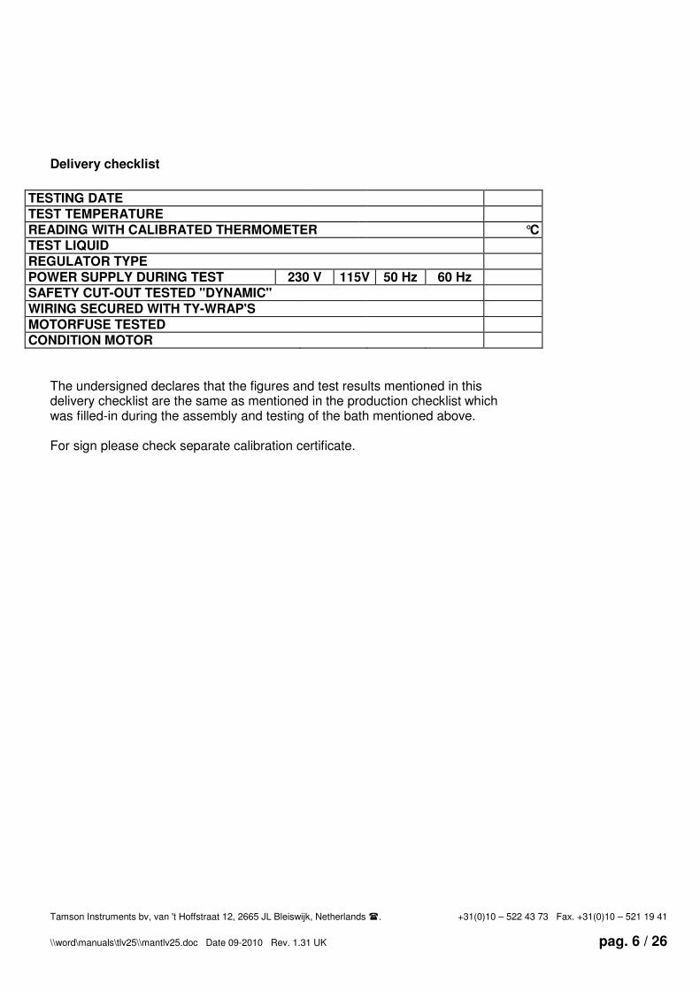
Delivery checklist
TESTING DATE
TEST TEMPERATURE
READING WITH CALIBRATED THERMOMETER °C
TEST LIQUID
REGULATOR TYPE
POWER SUPPLY DURING TEST 230 V 115V 50 Hz 60 Hz
SAFETY CUT-OUT TESTED "DYNAMIC"
WIRING SECURED WITH TY-WRAP'S
MOTORFUSE TESTED
CONDITION MOTOR
The undersigned declares that the figures and test results mentioned in this delivery checklist are the same as mentioned in the production checklist which was filled-in during the assembly and testing of the bath mentioned above. For sign please check separate calibration certificate.

Tamson Instruments bv, van 't Hoffstraat 12, 2665 JL Bleiswijk, Netherlands �. +31(0)10 – 522 43 73 Fax. +31(0)10 – 521 19 41
\\word\manuals\tlv25\\mantlv25.doc Date 09-2010 Rev. 1.31 UK pag. 7 / 26
Cooling TLV25 with KV40 and KV80 [Ref
TLV25_15.XLS]
-70.000
-60.000
-50.000
-40.000
-30.000
-20.000
-10.000
0
10.000
20.000
30.000
0:0
0
0:3
0
1:0
0
1:2
5
2:0
0
2:3
0
3:0
0
3:3
0
4:0
0
4:3
0
5:0
0
5:3
0
6:0
0
6:3
0
7:0
0
7:3
0
8:0
0
Time [hrs]
Te
mp
°C
KV80
KV40
The TLV25, general
The Tamson model TLV25, low temperature viscometer bath is designed to perform a variety of accurate temperature controls for e.g. low temperature viscosity measurements. The TLV25 system contains a 25 liter Dewar flask. The fluid in the flask must permanently be cooled by an external cryostat. The temperature set point is maintained via a microprocessor controlled heating element.
Depending on the type of cryostat used, minimum end temperatures of minus 30°, -60°C or -80°C can be reached. Temperatures are measured in 25 liters of Methanol with the KV40 and KV80 cryostats. At these minimum temperatures still enough energy is provided to maintain stable temperature when glas work is placed in the bath. The system accuracy conforms to ASTM D445 and ISO 3103 description. The bath is inside illuminated by a fluorescent light build-in behind the Dewar flask. The cryostat is a separate apparatus and must have enough capacity to cool 25 ltrs of liquid. It is further important that the cooling power supplied by the cryostat is very stable. It is for these reasons that we strongly recommend a combination of the TLV25 with the KV40 or KV80. Span Depending on the used cryostat:
- Minus 30°C with KV40
- Minus 60°C with KV80
- Minus 80°C with KV80S - Lower temperatures on request Accuracy
The set point can be set in steps of 0,1°C
from - 90°C up to plus 70°C. Overall
system accuracy is better than ±0,04°C. Read-out is on a 4 digit, 7 segment LED
display in 0.1 °C. On request read-oud
also is available in °F. Safety thermostat To prevent problems caused by a malfunctioning of the heating element the bath is equiped with a safety thermostat. This thermostat can not be adjusted, and
has a fixed preset value of 125°C. When for any reason the temperature of the bath will raise to this limit

Tamson Instruments bv, van 't Hoffstraat 12, 2665 JL Bleiswijk, Netherlands �. +31(0)10 – 522 43 73 Fax. +31(0)10 – 521 19 41
\\word\manuals\tlv25\\mantlv25.doc Date 09-2010 Rev. 1.31 UK pag. 8 / 26
the safety thermostat will cut the mains supply Circulation pumping device The bath is equipped with a special stirrer-pump combination which ensures a good uniformity. Condensation prevention To prevent build up of condesat onto the cold surface of the window, surface heaters have been installed around the window. A temperature sensor on the window keeps the surface temperature of the window just above the dew-point
under ambient conditions of up to 40 °C and 85% RH. Illumination An illuminator providing diffused fluorescent light for background lighting is mounted on the roar of the bath. It can be switched on and off with the switch-lamp on the control panel. Top plate The bath is supplied with a round lid with 3 holes 50 mm diameter to accept 3 capillary type viscometers in holders. Behind each viscometer position there is an opaque glass plate for easy reading of viscometer.
Installation
Tamson baths are carefully packed when they leave the factory to avoid damage during transport. Check the packing for any external damage and make a note on the shipping documents if any damage is found. Always retain the cartons and packing material until the bath has been tested and found in good condition, because transport companies generally will not honour a claim for damages if the respective box(es) is (are) not available for examination. - Clean inner bath thoroughly of any loose packing materials etc. - Place the bath in a level position. - Check operating voltage (230 V or 115 V) and connect the bath to appropriate mains supply. The bath has to be filled with a liquid suitable for operating temperature. WARNING: Never operate the bath without fluid !!!!
Filling and Bath liquids
Fill the bath up to 5 -10 mm below the lid. At no time should the bath level be allowed to fall 60 mm of the top plate. Depending on the bath temperature we advise the use of methanol as bath fluid.
Use a mains supply that is well earthened and clean of interferens and can carry
the load of the bath. Be sure to check the power requirements (230V / 115V)
marked on the tag plate at the back side of the bath.
When using a Cryostat KV80 or KV40, the use of the mixture water
and ethyleneglycol is not recommended because of the high capacity of the cooler.
(ice will grow on the evaporator causing poor heat exchange and unstable
temperature control )

Tamson Instruments bv, van 't Hoffstraat 12, 2665 JL Bleiswijk, Netherlands �. +31(0)10 – 522 43 73 Fax. +31(0)10 – 521 19 41
\\word\manuals\tlv25\\mantlv25.doc Date 09-2010 Rev. 1.31 UK pag. 9 / 26
Cooling
Low temperatures are reached with the use of a cryostat (immersion cooler). The top-plate of the bath provides a hole of 50 mm diameter to accept the evaporator of the immersion cooler. To reach temperature stability which conforms ASTM D445 only use the KV40 or KV80 as cryostat.
Heating
To reduce temperature fluctuations the cryostat provides stable cooling. To settle the bath temperature at a fixed set point a microprocessor controlled stainless steel heater regulates the temperature.
Operating the controller
The front panel layout of the controller is drawn below. Model 2216 front panel layout
Number Description 1 Output 1 2 N.A. 3 Set point active 4 N.A. 5 N.A. 6 Page button 7 Scroll button 8 Down button 9 Up button 10 Set point rate limit active 11 Lower readout 12 Upper readout
When the controller is activating the heater the indicator on the controller "OP1" will blink.
2216
OP1
OP2
SP2
REM
RUN MAN
1
4
3
2
5
6 7 8 9
10
11
12

Tamson Instruments bv, van 't Hoffstraat 12, 2665 JL Bleiswijk, Netherlands �. +31(0)10 – 522 43 73 Fax. +31(0)10 – 521 19 41
\\word\manuals\tlv25\\mantlv25.doc Date 09-2010 Rev. 1.31 UK pag. 10 / 26
Operation The front panel layout shows following 4 operating keys:
Page List Down Up
The “Page” Key offers following:
• Temperature readout in °C,
• Temperature set point in °C, value between –90 and +60°C, • Tuning the bath (“Atune”), • Changing the tuning (PID) parameters, • The ”List” Key will list the P, I, D, High Cutback and Low Cutback options, • Changing the temperature calibration offset,
• Programming the bath(ACCS). *This menu item has only been build in for servicing purpose and should not be used by users.
Up and Down keys allow changing the listed value. All changed values like set point and PID parameters will be kept in memory even after switching of the power supply. Quick start To start operating the bath in a quick way do following:
• Fill the bath with fluid until the level reaches 10 to 20 mm under the top plate,
• Place the power plug,
• Place cold finger/cryostat,
• Switch the bath on with the mains switch,
• Choose a working temperature (set point) with and ,
• Switch on the cryostat.
• Wait until the bath has reached its set point and choose ATUNE by pressing ,
• Now press and the display shows ”tune”,
• Press to choose “ON”,
• Press and together, the display will now alternate the values “tune” and the actual temperature,
• After a short period, depending on the set point temperature, the blinking of “tune” will stop and the bath
is ready for use.

Tamson Instruments bv, van 't Hoffstraat 12, 2665 JL Bleiswijk, Netherlands �. +31(0)10 – 522 43 73 Fax. +31(0)10 – 521 19 41
\\word\manuals\tlv25\\mantlv25.doc Date 09-2010 Rev. 1.31 UK pag. 11 / 26
What is tuning The temperature control of the bath is based on a digital PID system. Due to the use of different fluids in the bath with their own heat capacity, the use of external cooling and external connected processes(circulation), the PID parameters have to be optimized after changes to the system. Tuning of the bath results in:
• Stable temperature control of the bath,
• No over- or undershoot of the temperature set point,
• Quick response to deviations from the set point caused by external disturbances. Tuning can be done automatically or manually. The Parameters mentioned in Table 1 will influence the control of the bath.
Parameter Description Display Proportional band The bandwith in display-units over which the output power is
proportional between minimum and maximum Pb
Integration time Determines the time taken by the controller to remove stady state error signals
Ti
Derivative time Determines the time taken by the controller to react on error signals.
Td
Low cutback The number of degrees below set point at which the controller will cutback the output power in order to prevent overshoot on heat up.
Lcb
High cutback The number of degrees above set point at which the controller will cutback the output power in order to prevent undershoot on
cool down, important when working below 20°C.
Hcb
Relative offset Offset only shown for PD, or P control (I = off). [degrees] rES
Table 1 Parameters influencing the temperature control
A TLV25 system filled with methanol combined with a KV40 cryostat will give result following in table 2. Please note that values to your system can differ extremely due to ambient and system tolerances.
Set point
temperature °°°°C
Pb – values Ti – values[s] Td – values[s]
- 10 1,7 340 55 - 20 1,8 444 74 - 30 1,7 340 55
Table 2 PID values for a TLV25 with KV40
A TLV25 system filled with methanol and KV80 will give following results Set point
temperature °°°°C
Pb – values Ti – values[s] Td – values[s]
- 10 1,8 520 85 - 20 1,7 501 83 - 30 1,9 573 95 - 40 1,8 500 85 - 50 1,8 478 79
Table 3 PID values for a TLV25 with KV80

Tamson Instruments bv, van 't Hoffstraat 12, 2665 JL Bleiswijk, Netherlands �. +31(0)10 – 522 43 73 Fax. +31(0)10 – 521 19 41
\\word\manuals\tlv25\\mantlv25.doc Date 09-2010 Rev. 1.31 UK pag. 12 / 26
Automatic tuning
• Chose desired set point,
• Wait until the bath has reached the set point temperature,
• Choose with key Atune,
• Press key option “Tune”,
• Choose with key “on”,
• Press key and simultaneous, the display will show alternating the word “tune”.
The controller will shortly oscillate the temperature in the bath and from the reaction of the bath it will calculate the “P”, “I” and “D” parameter. It will store these parameters and returns to its controlling function. The bath will show its actual temperature on the display. The tuning parameters are kept in memory after
power has been shut off. The time needed for auto tuning the system depends mainly on the cool-down time of the bath. Due to thermo dynamic law the tuning time behaves like an exponential function of the bath temperature. Auto tuning should in all cases give you an optimal result. There are cases in which you want to tune by hand and set the PID parameters yourself. Following will describe how to manage that.
• Choose set point temperature,
• Wait until the bath has reached its set point temperature,
• Choose key to show PID,
• Press for Ti or Td parameter,
• Change the value or press enough times so that the display shows “Off”,
• Choose with Atune,
• Press to show “Tune”,
• Press for “on”,
• Press and to confirm tuning and display will alternate “tune” and bath temperature,
If PI or P control has been chosen, the reached end temperature in the bath will always deviate from the set point temperature. To eliminate this error, the value off the error has to be appointed to the rES parameter in the PID menu. This parameter will only be visible when P or PI control is activated. To eliminate the error offset do following:
• Choose PID with ,
• Press for rES,
Tip. To allow optimal temperature control of the bath fluid, the bath has to be tunded
after following changes:
- Other type of fluid used in the bath,
- Change of fluid level
- Setoint which deviates more than 5°°°° of previous tuning set point,

Tamson Instruments bv, van 't Hoffstraat 12, 2665 JL Bleiswijk, Netherlands �. +31(0)10 – 522 43 73 Fax. +31(0)10 – 521 19 41
\\word\manuals\tlv25\\mantlv25.doc Date 09-2010 Rev. 1.31 UK pag. 13 / 26
• Adjust value to eliminate offset with and ,
• Press and at the same time to confirm and show bath temperature reading.
Manual tuning The parameters for the PID control can also be changed manually. Again this procedure is only to be followed when automatic tuning is not functioning. PID parameters can be accessed by pressing:
• Key for 3 times, display shows “PID”,
• Key , display shows PD which is the proportional value,
• Change PD value with and ,
• Key , display shows Ti which is the integrator value in seconds,
• Change Ti value with and ,
• Key , display shows Td which is derivate value in seconds,
• Change Td value with and ,
• Key , display shows Lcb,
• Do not change “auto” value,
• Key , display shows Hcb,
• Press and at the same time to confirm and show bath temperature reading.
The control also allows to set the I and D values to zero. The bath will then function as a proportional system. The “P” parameter can than be varied to an optimal value by trial and error. A higher P will stabilize the system when I and D are off. The PID parameters can also be determined with the use of the Ziegler Nichols method described below. Manual tuning by Ziegler-Nichols With the process at its normal running temperature: 1 Set the integral time “Ti” and the derivate Time “Td” to off 2 Check if the Lcb and Hcb are set to auto 3 Ignore the fact that the temperature may not settle precisely at the set point 4 If the temperature is stable, reduce the proportional band Pb so that the temperature just starts to
oscillate. If the temperature is already oscillating, increase the proportional band until it starts oscillating. Allow enough time between each adjustment for the loop to stabilize. Make a note of the proportional band value “B” and the period of oscillation “T” Set the Pb, Ti and Td parameter values according to the calculations given in the table below
Type of control Proportional band “Pb” Integral time “Ti” Derivative time “Td”
Proportional only 2*B Off Off P + I control 2,2*B 0,8*T Off P + I + D control 1,7*B 0,5*T 0,12*T

Tamson Instruments bv, van 't Hoffstraat 12, 2665 JL Bleiswijk, Netherlands �. +31(0)10 – 522 43 73 Fax. +31(0)10 – 521 19 41
\\word\manuals\tlv25\\mantlv25.doc Date 09-2010 Rev. 1.31 UK pag. 14 / 26
Overshoot
Time
T Undershoot
Time
T
Setting the cutback values The above procedure sets up the parameters for optimum stady state control, If unacceptable levels of overshoot or undershoot occur during start-up for large step changes in temperature, then manually set the cutback parameters Lcb and Hcb. Set the low and high cutback values to three times the proportional bandwith (That is to say, Lcb = Hcb = 3 * Pb) See the examples in drawing 2 and 3 for over- and undershoot. Drawing 2 Drawing 3
Set point Set point

Tamson Instruments bv, van 't Hoffstraat 12, 2665 JL Bleiswijk, Netherlands �. +31(0)10 – 522 43 73 Fax. +31(0)10 – 521 19 41
\\word\manuals\tlv25\\mantlv25.doc Date 09-2010 Rev. 1.31 UK pag. 15 / 26
Faultfinding
The motor is not running and the lamps are not on. Check the main voltage and all electrical connections, including switches.
Mechanical over temperature cut-out +70 °C is de-activated and can be reset by pressing the reset button on the back panel near the power supply cable. Mechanical max. current protection ( 16A ) is de-activated. This fuse is located on the back panel of the TLV25 Motor is not running, lamps and electronics operate and the motor turns freely by hand. Motor fuse has deactivated motor. Reset fuse by pushing button on panel. Motor overloaded. The motor protection may trip because of mechanical overloading of the pump. The 7 µF capacitor is faulty. Replace motor capacitor located behind the front panel. Loose connection is possible. Check wiring at rear of motor cover. Minimum temperature is not reached There are three possible causes: 1) The KV80 is defective 2) There is a lot of ice forming around the KV80 probe 3) The methanol used is very poluted with water due to condensat and ice forming Ad 1)The KV80 can only be tested on performance when the TLV25 is completely free of ice and the methanol used is fresch. The cooling down period of the KV80/TLV25 combination is indicated in the manual see chapter “The TLV25, general”, page 7.
If the minimum temperature is not reached the filling of the refrigerant inside the KV80 is not ok. The unit should be repaired. This is a tecnical proces only specialized companies can perform. Ad 2+3) Free all ice from the TLV25 and KVprobe and hose. Let the unit dry in ambient and make sure there is no moisture absorbed in the tubing of the KV80. The combination KV80/TLV25 needs good maintenance. Refresh the methanol in teh TLV25. It's preferred to keep the unit in a moisture free environment and prevent ice from growing on the machine. Regularly remove ice if neccessary.

Tamson Instruments bv, van 't Hoffstraat 12, 2665 JL Bleiswijk, Netherlands �. +31(0)10 – 522 43 73 Fax. +31(0)10 – 521 19 41
\\word\manuals\tlv25\\mantlv25.doc Date 09-2010 Rev. 1.31 UK pag. 16 / 26
Technical Specs TLV25
Item Unit TLV25
Window [mm] 148*213 Setting ± [°C] 0,1 Stability [°C] ±0,03
Heating [W] 780 Heaters 1
Bath volume [L] 25 Opening [mm] 162(diameter) Depth [mm] 400
Length [mm] 570 Width [mm] 410 Heigth [mm] 540 Opening Cold Finger
[mm] Diameter: 50 * Length 240
Weight [kg] 55
Power [Watt] 920 Voltage [Volt] 230/115

Tamson Instruments bv, van 't Hoffstraat 12, 2665 JL Bleiswijk, Netherlands �. +31(0)10 – 522 43 73 Fax. +31(0)10 – 521 19 41
\\word\manuals\tlv25\\mantlv25.doc Date 09-2010 Rev. 1.31 UK pag. 17 / 26
Spare part list TLV25
TLV25 115 and 230 volts
Part number 230 Volts 115 Volts
Description
04T0100 04T0200 Pump assembly with motor 24T3300 n.a. Capacitor 7uF
n.a. 24T3330 Capacitor 25uF 24T8080 n.a. Motorfuse 0.6 Amps
n.a. 24T8090 Motorfuse 1.3 Amps 05T1160 05T1180 Stainless steel heater 24T9180 24T9190 Heater – on – lamp 28T3015 28T3015 Temperature controller 85..250V
24T8540 Mains Switch 25T2320 PT-100 115 mm 24T7080 Wall socket 24T9250 Fluorescent lamp 06T0377 PCB window heating 25T0140 Window heating 40W
2 Placed parallel @ 115V 2 placed in series @ 230V
28T0091 Sensor + wires preprogrammed for TLV25 window heating
06T0385 PCB with mains FILTER 06T1870 PCB filter for temperature controller 24T8420 Solid state 24T8585 Thermostat 26T1420 Dewar flask

Tamson Instruments bv, van 't Hoffstraat 12, 2665 JL Bleiswijk, Netherlands �. +31(0)10 – 522 43 73 Fax. +31(0)10 – 521 19 41
\\word\manuals\tlv25\\mantlv25.doc Date 09-2010 Rev. 1.31 UK pag. 18 / 26
CRYOSTAT KV-Series
EC declaration of conformity cryostat
Manufacturer: Tamson Instruments B.V. van 't Hoffstraat 12 2665 JL Bleiswijk The Netherlands Product: Cryostat Immersion Cooler Model: Tamson KV40 and KV80 The products to which this statement relates, are manufactured and dully carried out in compliance with following CE norms: - EN 292 - Pr EN 378 - EN 60204 - RLK. 97. Maximum working pressure level of 30 bar is confirmed. The equipment conforms with all the specifications and norms in this regard. The equipment conforms without any further notice. On each apparatus following pressure and leak tests have been carried out with positive result - Low pressure side 20 bar - High pressure side 30 bar Zoetermeer, The Netherlands Ing. R.C. van Hall Director

Tamson Instruments bv, van 't Hoffstraat 12, 2665 JL Bleiswijk, Netherlands �. +31(0)10 – 522 43 73 Fax. +31(0)10 – 521 19 41
\\word\manuals\tlv25\\mantlv25.doc Date 09-2010 Rev. 1.31 UK pag. 19 / 26
Cryostat, Installation and use
Put the unit in its proper place. Leave enough room around the cryostat for sufficient air circulation. Place the unit in a clean working environment and keep away from dust. When air can not circulate well the cryostat will overheat itself resulting in irreversible and severe mechanical damage. Dust will block the condensor and might also cause overheating of the system. Overheating will cause severe damage to the compressor. The cold finger can be placed in the TLV25 holder, next to the three opening lids for the viscosity meter holders. When the TLV25 is fully filled with methanol the cryostat can be switched on. In all cases water is not recommended to use in combination with a cryostat. Water will freeze very quick around the cooling coil preventing proper energy exchange between the cold finger and the bath fluid. It is possible to cool down other processes with the cold finger i.e. rapidly lower temperature in hot fluids. It is
not recommended to permanently cool fluids with a temperature above 80°C. Pressure inside the evaporator circuit will be extremely high and can causing severe thermal damage to the compressor. Regularly check:
The apparatus to see if airflow is not blocked around apparatus, Apparatus and condensor are free from dust, Hose is not mechanically damaged.
Cryostat fails to operate Check if apparatus is switched on and power is on mains. Check mains fuse. The KV40 has no fuse build in, the KV80 has a fuse on the front panel next to the power switch.
• Fan does not function Check wiring inside apparatus and see if nothing is blocking the fan
• Ventilator makes noise Open apparatus and check blocking of the fan. After several years bearings can be worn out. replace fan.
• Ice forming on cold finger Water vapour in the air condensates on the top of the cold finger. In time this ice will grow, forming a block of ice. Turning of the cryostat and let the ice melt, or prevent air from forming condensate by insulating the cold finger.
• Bad cooling due to forming of ice (crystals). Do not use water or water glycerine mixture as a bath medium. Instead use methanol.
It is advised not to move the refrigeration hose at low temperatures. Only move the
apparatus and hose when switched off and cold finger at room temperature.

Tamson Instruments bv, van 't Hoffstraat 12, 2665 JL Bleiswijk, Netherlands �. +31(0)10 – 522 43 73 Fax. +31(0)10 – 521 19 41
\\word\manuals\tlv25\\mantlv25.doc Date 09-2010 Rev. 1.31 UK pag. 20 / 26
Cooling 40 litres of oil down from different
temperatures with KV40 (a,b,d,f) and without
(c,e,g) [Ref. TV40_30A.XLS]
20.000
30.000
40.000
50.000
60.000
70.000
80.000
90.000
100.000
110.000
120.000
130.000
140.000
150.000
160.000
170.000
0:0
0
2:0
0
4:0
0
6:0
0
8:0
0
10
:0
12
:0
14
:0
16
:0
17
:0
20
:0
Time [hrs]
Tem
pera
ture
[°C
]
a
b
c
d
e
f
g
KV40 Cryostat
The KV40 is designed for cooling down fluid in viscometer baths. The combination of the KV40 and our low temperature viscosity measurement bath TLV25, allows stable viscosity measurements at temperatures with a
minimum of minus 30°C. To work at different temperatures, a microprocessor controlled heating element inside the TLV25 system heats the fluid against the constant cooling capacity of the KV40 cryostat.
Stable regulation of the KV40 / TLV25 combination is guaranteed for all working temperatures with a minimum of approximately 2 degrees above the combinations’ minimum temperature. This minimum temperature of –32’C is reached when the TLV25-heating is fully off. The cooling probe of the system is formed by a stainless steel coil at the top of a flexible hose. This probe can be immersed in the cooling fluid. The KV40 - cooling power is measured in a Dewar flask containing 10 litres of methanol. All measured values are based on a TLV25 system filled with 25 litres methanol.
The KV-system is guaranteed CFK/HCFK free.
Cooling power KV40 [Ref 40&80_2.XLS]
0
50
100
150
200
250
300
350
400
450
-40 -30 -20 -10 0 10 20 30
Temperature[°C]
Po
wer
[Watt
]

Tamson Instruments bv, van 't Hoffstraat 12, 2665 JL Bleiswijk, Netherlands �. +31(0)10 – 522 43 73 Fax. +31(0)10 – 521 19 41
\\word\manuals\tlv25\\mantlv25.doc Date 09-2010 Rev. 1.31 UK pag. 21 / 26
Cooling methanol with KV40 [Ref. KV40_1a.XLS]
-90.000
-80.000
-70.000
-60.000
-50.000
-40.000
-30.000
-20.000
-10.000
0
10.000
20.000
30.000
0:0
0:0
0
0:0
7:1
7
0:1
4:3
4
0:2
1:5
1
0:2
9:0
8
0:3
6:2
5
0:4
3:4
2
0:5
0:5
9
0:5
8:1
6
1:0
5:3
3
1:1
2:5
0
1:2
0:0
7
1:2
7:2
4
1:3
4:4
1
1:4
1:5
8
1:4
9:1
5
1:5
6:3
2
2:0
3:4
9
2:1
1:0
6
2:1
8:2
3
2:2
5:4
0
2:3
2:5
7
Time [hrs]
Te
mp
°C
KV40 - 5 Ltrs
KV40 - 10Ltrs
KV40 - 15Ltrs
KV40 - TLV25
Technical Specs KV40
Item Unit KV40
Body Stainless Steel PET
Hose length [mm] 2500
Probe length [mm] 190
Probe diameter [mm] 47
Length [mm] 390
Width [mm] 310
Height [mm] 360
Weight [kg] 25
Power [Watt] 600
Voltage [Volt] 230 115 on request
Using the KV for other cooling purposes The KV40 can also be used to provide cooling power in a specific process. Examples are cooling down liquids more rapidly or lower temperature of a specific process. The cold finger can be used for this purpose as a “cold spot”. In fluids the finger can be immersed or the finger can be mounted just to cool down gas in a process.
It is important not to continuously heat the cold finger. Immersing the finger in fluids of over 100°C for a period over more than 2 hours will harm the compressor. The pressure of the cooling gas inside the finger will raise dramatically due to these high temperatures. This raise in pressure causes the compressor to work harder and heat up. Overheating on the long term can overheat and severely damage the cold finger on the long term.

Tamson Instruments bv, van 't Hoffstraat 12, 2665 JL Bleiswijk, Netherlands �. +31(0)10 – 522 43 73 Fax. +31(0)10 – 521 19 41
\\word\manuals\tlv25\\mantlv25.doc Date 09-2010 Rev. 1.31 UK pag. 22 / 26
Ordering codes KV40
Item Voltage Ordering code
KV40 230V/50Hz 00T0212
KV40 230V/60Hz 00T212A
KV40 115V/60Hz 00T0260 Spare part list KV40
KV40 Part numbers Description
28T8001 Casing (PET) 28T8002 Wheel
28T8003 Wheel with break 28T8004 Power cord
28T8005 Mains switch
28T1332 Fan Condensor Bi-Sonic 5E 230B, 339m3 230V/60Hz 170x150x55
28T8007 Condensor
28T8008 Compressor 28T8009 Starter set for compressor
28T8010 Cold finger with 2500 mm hose 28T8011 Grip casing
28T8012 Dryer Principal diagram KV40
M Compressor
Condens Evaporator
Cappulair
Filter

Tamson Instruments bv, van 't Hoffstraat 12, 2665 JL Bleiswijk, Netherlands �. +31(0)10 – 522 43 73 Fax. +31(0)10 – 521 19 41
\\word\manuals\tlv25\\mantlv25.doc Date 09-2010 Rev. 1.31 UK pag. 23 / 26
KV80 Cryostat
The KV80 is designed to cool down fluids. The combination of the KV80 and our low temperature viscosity measurement bath TLV25, allows very stable viscosity measurements at low temperatures. To work at different temperatures, a microprocessor controlled heating element inside the TLV25 system heats the fluid against the constant cooling capacity of the KV80 cryostat. Stable regulation of the KV80 / TLV25 combination is guaranteed for all working temperatures with a minimum of approximately 2 degrees above the combinations minimum temperature. This minimum temperature is reached when the
heating from the is TLV25 fully off and lies around minus 65°C. The cooling probe of the system is formed by a stainless steel coil at the top of a flexible hose. This probe can be immersed in the cooling fluid. Temperatures mentioned here have been measured with methanol. The KV80 cooling capacity has been measured in a Dewar flask with 10 litres of methanol. The KV-system is guaranteed CFK/HCFK free.
Technical Specs KV80
Item Unit KV80
Body Stainless Steel
Hose length [mm] 2500
Probe length [mm] 190
Probe diameter [mm] 47
Length [mm] 560
Width [mm] 450
Height [mm] 500
Weight [kg] 60
Power [Watt] 1200
Voltage [Volt] 230 115 on request
Using the KV for other cooling purposes The KV40 can also be used to provide cooling power in a specific process. Examples are cooling down liquids more rapidly or lower temperature of a specific process. The cold finger can be used for this purpose as a “cold spot”. In fluids the finger can be immersed or the finger can be mounted just to cool down gas in a process.
It is important not to continuously heat the cold finger. Immersing the finger in fluids of over 100°C for a period over 2 hours will harm the compressor. The pressure of the cooling gas inside the finger will raise dramatically due to these high temperatures. This raise in pressure causes the compressor to work harder and heat up. Overheating on the long term can overheat and severely damage the cold finger on the long term.

Tamson Instruments bv, van 't Hoffstraat 12, 2665 JL Bleiswijk, Netherlands �. +31(0)10 – 522 43 73 Fax. +31(0)10 – 521 19 41
\\word\manuals\tlv25\\mantlv25.doc Date 09-2010 Rev. 1.31 UK pag. 24 / 26
Cooling power KV80 [Ref 40&80_2.XLS]
0
50
100
150
200
250
300
350
400
450
-80 -70 -60 -50 -40 -30 -20 -10 0 10 20 30
Temperature[°C]
Po
wer
[Watt
]
Cooling methanol with KV80 [Ref. KV40_1a.XLS]
-90.000
-80.000
-70.000
-60.000
-50.000
-40.000
-30.000
-20.000
-10.000
0
10.000
20.000
30.000
1
20
39
58
77
96
11
5
13
4
15
3
17
2
19
1
21
0
22
9
24
8
26
7
28
6
30
5
32
4
34
3
36
2
38
1
40
0
Time [hrs]
Tem
p °
C KV80 - 10 Ltrs
KV80 - 15 Ltrs
KV80 - TLV25
Ordering codes KV80
Item Voltage Ordering code
KV80 230V/50Hz 00T0216
KV80 230V/60Hz 00T216A KV80 115V/60Hz 00T0260

Tamson Instruments bv, van 't Hoffstraat 12, 2665 JL Bleiswijk, Netherlands �. +31(0)10 – 522 43 73 Fax. +31(0)10 – 521 19 41
\\word\manuals\tlv25\\mantlv25.doc Date 09-2010 Rev. 1.31 UK pag. 25 / 26
Spare part list KV80
KV80 Part numbers Description
28T8013 Casing (PET) 28T8014 Wheel
28T8015 Swing wheel with break/lock
28T8004 Power cord 28T8005 Mains switch
28T8016 Switch with magnet 28T8017 Terminals
28T8018 DIN Rail 28T8019 High pressure pressiostat
28T8020 Low pressure pressiostat
28T8021 Mounting plate fan 28T8023 Condensor
28T8008 Compressor 28T8009 Starter set for compressor
28T8024 Heat exchange module 28T8006 FAN Motor ELCO
T4VN10 10 / 38 -0,23A

Tamson Instruments bv, van 't Hoffstraat 12, 2665 JL Bleiswijk, Netherlands �. +31(0)10 – 522 43 73 Fax. +31(0)10 – 521 19 41
\\word\manuals\tlv25\\mantlv25.doc Date 09-2010 Rev. 1.31 UK pag. 26 / 26
Compressor Condensor Evaporator
Cappulair
Filter
Compressor Condens
Cappulair
Filter
Intermediate cooler
Principal diagram KV80
DISCLAIMER Information given herein is offered in good faith as accurate, but without guarantee. Conditions of use and suitability of the product for particular uses are beyond our control; all risks of use of the product are therefore assumed by the user and
We expressly disclaim all warranties of every kind and nature, including warranties of merchantability and fitness for a particular purpose in respect to the use or suitability of the product.
Nothing is intended as a recommendation for uses which infringe valid patents or as extending license under valid patents. Appropriate warnings and safe handling procedures should be provided to handlers and users. Alteration of this document is strictly prohibited. Except to the extent required by law, republication or retransmission of this document, in whole or in part, is not permitted. Tamson Instruments bv assume no responsibility for accuracy of information unless the document is the most current available. Tamson Instruments neither represent nor warrant that the format, content or product formulas contained in this document comply with the laws of any other country except the Netherlands. Tamson Instruments bv, All rights reserved
M
First Second stage