
MANUAL REV 1 · INSTALLATION MANUAL OPERATION MANUAL MAINTENANCE MANUAL REVISION 1.2 January 28,...
32
MODEL E-04C 121.5/406 MHZ ELT INSTALLATION MANUAL OPERATION MANUAL MAINTENANCE MANUAL REVISION 1.2 January 28, 2015 Part Number E-04CM TECHNOLOGIES INC. AVIONICS FOR GENERAL AND COMMERCIAL AVIATION
Transcript of MANUAL REV 1 · INSTALLATION MANUAL OPERATION MANUAL MAINTENANCE MANUAL REVISION 1.2 January 28,...

MODEL E-04C
121.5/406 MHZ ELT
INSTALLATION MANUAL
OPERATION MANUAL
MAINTENANCE MANUAL
REVISION 1.2 January 28, 2015
Part Number E-04CM
TECHNOLOGIES INC.
AVIONICS FOR GENERAL AND COMMERCIAL AVIATION

2
RECORD OF CHANGES
REV DESCRIPTION OF CHANGE DATE BY
1.0 INITIAL MANUAL 12/06/2013 MA
1.1 Add antennas CI 319-1-1 AV-300 –1, Add inrush current data, Add E-04.3 Packing list, Correct minor typographical errors
07/08/2014 MA
1.2 Added grounding detail, waterproof remote switch cover 01/28/2015 MA
Prepared by Mike Akatiff ____________________________________________________ Date 12/06/2013
Project Engineer
Checked by Greg Akatiff _____________________________________________________ Date 12/06/2013
QC manager
Approved by Greg Akatiff ____________________________________________________ Date 12/06/2013
QC manager

3
TABLE OF CONTENTS
PAGE
Section 1 406 MHz ELT system description and packing lists 4
MECHANICAL INSTALLATION
Section 2 ELT installation 7
Section 3 Antenna installation 10
ELECTRICAL INSTALLATION
Section 4 Wiring diagram 15
Section 5 Harness fabrication 16
Section 6 Final installation 17
OPERATION
Section 7 Registration 18
Section 8 Operation and self test 19
MAINTENANCE
Section 9 Battery replacement 21
Section 10 Periodic maintenance / Continuing airworthiness 23
Section 11 Canadian maintenance requirements 24
SPECIFICATIONS
Section 12 Specifications 25
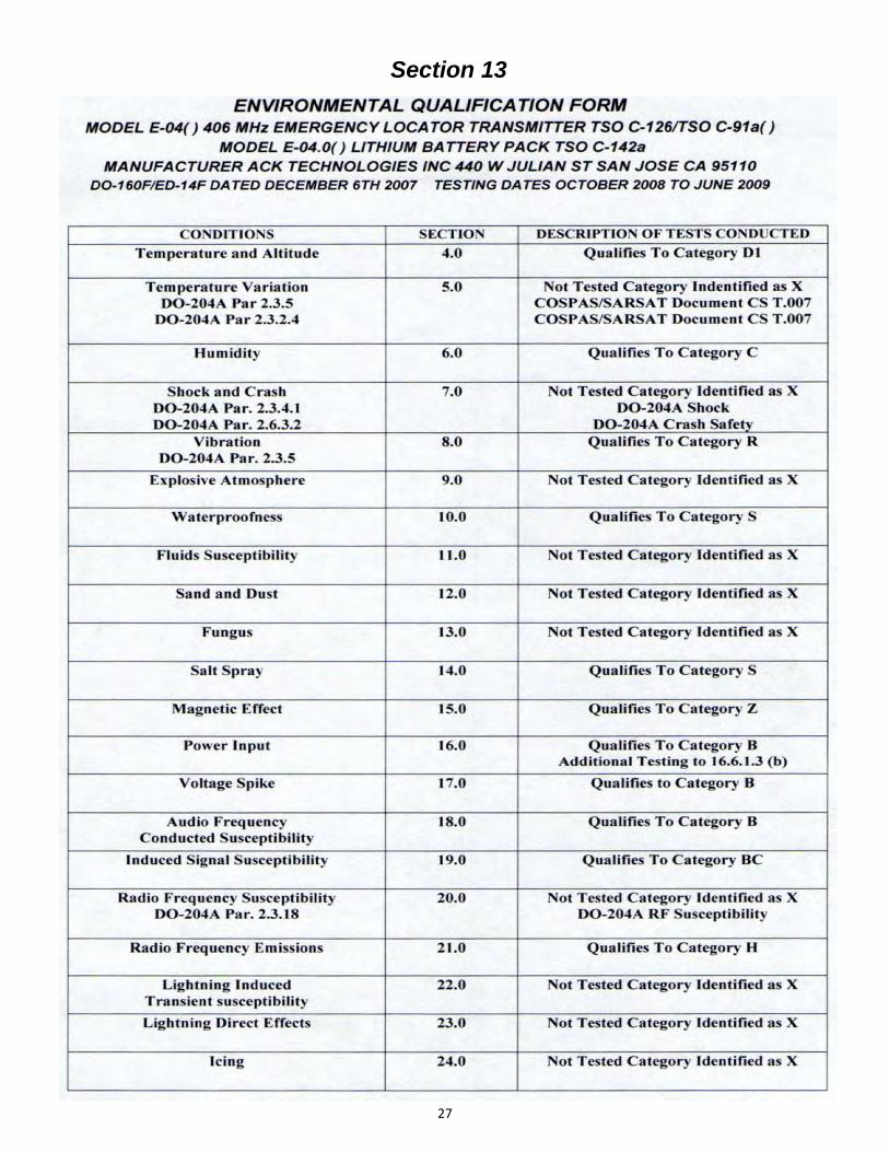
Section 13 Environmental qualifications DO-160F/ED-14F 27
Section 14 Data formats / Installation notes 29
Section 15 Major parts 31
WARRANTY
Section 16 WARRANTY 32
4
Section 1
E-04C SYSTEM DESCRIPTION
The model E-04C Emergency Locator Transmitter is designed to meet the needs of corporate and transport category aircraft. It’s design is the result of the experience and knowledge gained over twenty years and 71,000 units of 121.5/243 and 121.5/406 MHz ELT production. The model E-04 incorporates the latest electronic technology available in the Silicon Valley where ACK Technologies, Inc. is located. The model E-04C will accept and store external position data from ARINC 429 high or low speed busses, GPS messages from Garmin, Bendix/King and NMEA 0183 formats. The model E-04 may be installed without connection to position data however we strongly recommend that external data be provided to the ELT if it is available in the aircraft. The model E-04C has been certified under TSO-C126, TSO-C126b, TSO-C91a, and TSO-C142a and holds certification from US, Canadian, Brazilian and European authorities.
PACKING LIST
E-04C With ACK Mach 1 High speed blade antenna
Quantity Part Number Description_________________________________
1 E-04C 121.5/406 MHz Emergency Locator Transmitter
2 E-04.5.1 Remote control with vertical placard
1 E-04.5.1.0H Remote horizontal placard
1 S65-1231-1 Blade antenna
1 E-04.10.4 Coax cable 60”
1 E-04.10.1.11 Warning horn
1 E-04.4 Mounting Tray
1 E-04.4.1 Retaining strap front
1 E-04.4.2 Retaining strap battery case
1 E-04.10.1.13K 2 Pin plug kit
1 E-04.10.1.4K 8 Pin circular plug kit
1 E-04.10.1.10K 15 Pin plug kit
1 E-04.10.11.1 Switch cover
1 N/A Antenna drill template
1 E-04CM Installation/Operation/Maintenance Manual

5
PACKING LIST E-04C.1 With ACK E-04.8 Whip antenna
Quantity Part Number Description_________________________________
1 E-04C 121.5/406 MHz Emergency Locator Transmitter
2 E-04.5.1 Remote control with vertical placard
1 E-04.5.1.0H Remote horizontal placard
1 E-04.8 Whip antenna
1 E-04.10.1.12 Electrostatic discharger
1 E-04.10.4 Coax cable 60”
1 E-04.10.1.11 Warning horn
1 E-04.4 Mounting Tray
1 E-04.4.1 Retaining strap front
1 E-04.4.2 Retaining strap battery case
1 E-04.10.1.13K 2 Pin plug kit
1 E-04.10.1.4K 8 Pin circular plug kit
1 E-04.10.1.10K 15 Pin plug kit
1 E-04.11.1 Switch cover
1 E-04CM Installation/Operation/Maintenance Manual
PACKING LIST E-04C.2 with no antenna
Quantity Part Number Description_________________________________
1 E-04C 121.5/406 MHz Emergency Locator Transmitter
2 E-04.5.1 Remote control with vertical placard
1 E-04.5.1.0H Remote horizontal placard
1 E-04.10.4 Coax cable 60”
1 E-04.10.1.11 Warning horn
1 E-04.4 Mounting Tray
1 E-04.4.1 Retaining strap front
1 E-04.4.2 Retaining strap battery case
1 E-04.10.1.13K 2 Pin plug kit
1 E-04.10.1.4K 8 Pin circular plug kit
1 E-04.10.1.10K 15 Pin plug kit
1 E-04.11.1 Switch cover
1 E-04CM Installation/Operation/Maintenance Manual

6
PACKING LIST E-04C.3 With ACK AV-300-1 350 Knot rod antenna
Quantity Part Number Description_________________________________
1 E-04C 121.5/406 MHz Emergency Locator Transmitter
2 E-04.5.1 Remote control with vertical placard
1 E-04.5.1.0H Remote horizontal placard
1 AV-300-1 Rod antenna
1 E-04.10.1.12 Electrostatic discharger
1 E-04.10.4 Coax cable 60”
1 E-04.10.1.11 Warning horn
1 E-04.4 Mounting Tray
1 E-04.4.1 Retaining strap front
1 E-04.4.2 Retaining strap battery case
1 E-04.10.1.13K 2 Pin plug kit
1 E-04.10.1.4K 8 Pin circular plug kit
1 E-04.10.1.10K 15 Pin plug kit
1 E-04.11.1 Switch cover
1 E-04CM Installation/Operation/Maintenance Manual
7
Section 2
ELT INSTALLATION
The methods and guidance of AC 43.13-2B should be followed when installing the ELT
Fixed wing Aircraft
Generally the most suitable location for fixed wing aircraft, is to position the ELT transmitter in the fuselage as far aft as possible. Antenna location, and accessibility for maintenance, are
factors that should be considered when choosing a mounting location. A location near the center of the airframe is acceptable. The ELT must be mounted with the arrow printed on the
battery case pointing in the direction of flight. The ELT should be mounted with it’s longitudinal axis aligned within 10 degrees of the longitudinal axis of the aircraft fuselage.
Avoid mounting the ELT near sources of strong EMI/RFI radiation as shown in Figure 1 on page 8.
Helicopter installation
The model E-04C ELT is suitable for helicopter installation. The procedures for installation, maintenance, and operation, are the same as for fixed wing aircraft, except for the orientation of the ELT in relation to the helicopter longitudinal axis. The arrow on the battery case of the ELT should be pointed in the normal direction of forward flight. The longitudinal axis should be aligned within +- 10 degrees of the longitudinal axis horizontally, and at a 45 degree downward angle as shown in Fig 2 on page 8.
Mounting tray installation
RTCA document DO-204 paragraph 3.1.8. prescribes the mounting requirements which must be met when installing this ELT, these requirements are as follows:
“The ELT shall be mounted to primary load‐carrying structures such as trusses, bulkheads, longerons, spars,
or floor beams. (not aircra skin) The mounts shall have a maximum sta c local deflec on no greater than
2.5mm (0.1 inch) when a force of 450 newton's (100 lbs.) is applied to the mount in the most flexible
direc on. Deflec on measurements shall be made with reference to another part of the airframe not less
than 0.3 meter (1 foot) nor more than 1.0 meter (3 feet) from the moun ng loca on.”
A doubler plate may be required. This measurements should be taken .5” above the base of the ELT. After selecting a suitable location meeting all of the above requirements. Drill and mount the ELT tray assembly as shown in Figure 3 on page 8.
IMPORTANT
The quick release retaining straps which secure the ELT to the tray are slightly different in size. The strap that fits around the front of the ELT, (transmitter assembly) is marked “Front.” The strap that fits around the battery case end of the ELT, is marked “Battery”
Figure 3 page 8.
Audio alert installation
The audio alert may be either mounted through the panel by drilling an 11/16” hole through the panel or may be mounted using two 4-40 screws on a flat surface as shown in Figure 4 on page . The audio alert should be mounted in the cockpit where it can be heard by the pilot and maintenance personal.

8

9
Remote control installation
The remote control should be mounted in the cockpit where it is visible and within reach of the pilot or copilot. Both a vertical and horizontal placards are supplied with the ELT. Chose a location and orientation that meets the above requirements. Allow an additional 2” behind the remote to allow for connection to the 15 pin Sub D connector. A right angle hood may be used if there is limited depth behind the panel location Northern Technologies P/N N30E900000 (Allied Electronics P/N 70172244) 90 degree hood allows for 1” clearance behind the remote. If a waterproof connector is needed an IP67 connector is available from Assmann Components P/N A-HDS15-HOOD-WP-R. (Digi-Key P/N AE10119-ND) to use this connector 2.750” clearance behind the remote is required. Figure 5 shows the remote dimensions and the panel cutout requirements. See Figure 6 to set the data format and rate.
A waterproof cover is available P/N E-04.10.1.14 and should be used if the remote is mounted vertical or is subject to liquid contamination.
Set the ARINC 429 high or low speed or GPS position data input by installing jumpers as shown.
See page 22 Figure 4 for remote PC board removal.
WATERPROOF COVER

10
Section 3
ANTENNA INSTALLATION
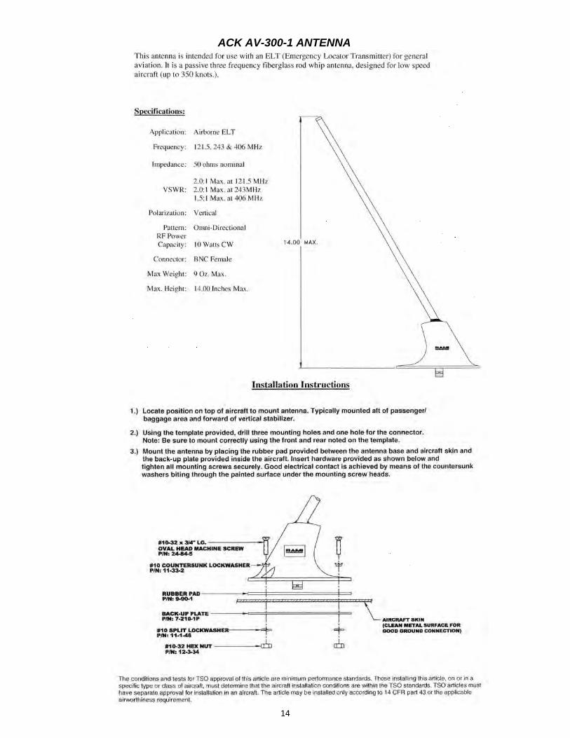
In order to meet the requirements of COSPAS/SARSAT, TSO C-126b,TSO C-91a, and FAR 91.207 an approved antenna must be used. We have available four approved antennas suitable for use with the model E-04C ELT. ACK P/N E-04.8 is a monopole, dual frequency antenna design. It has a recommended operating speed of up to 260 knots. This antenna is not recommended for flight in known icing conditions. ACK P/N S65-1231-1 is a high speed blade which is rated to Mach 1.0. ACK AV-300-1 is a rod type antenna for use up to 350 knots. ACK CI 319-1-1 is a fiberglass blade antenna for use up to 600 knots. Other existing antennas may be used provided they meet approval for use with the model E-04 ELT. Page 13 lists other manufacturers antennas that are approved for use with the Model E-04C. The coaxial cable supplied is RG-58, and is 5 feet long. A longer or shorter cable may be fabricated using RG-58 or equivalent cable, and Amp 227079-5 or equivalent connectors. The insertion loss of the cable assembly at 406 MHz should not exceed 2 dB. At 121.5 MHz the insertion loss should not exceed 3 dB. The cable should be a minimum of 2 feet in length (.25 Db minimum loss). The antennas may be mounted internally in composite construction, and tubular fabric covered aircraft, as long as the fabric or composite material is of a non conductive nature. The antenna must be mounted externally on airframes of metallic construction. The antenna should be mounted as close to the ELT transmitter as practical. The coaxial cable connecting the antenna to the ELT transmitter, should not run in close proximity to comm radio coaxial cables, and should avoid crossing aircraft production breaks. (i.e. riveted fuselage sections) The antenna must be mounted within 40 degrees of vertical when the aircraft is in normal flight attitude. The installed antenna must be able to withstand a static load of 100 (one hundred) times it’s weight (13 lbs.) applied to the base of the antenna, along the longitudinal axis of the aircraft. The antenna should be mounted a minimum distance of three feet (1 meter) from any vertically polarized communication antennas. (i.e. Antennas radiating in the 118-137 MHz band.) and 4 feet from GPS antennas
MODEL E-04.8 WHIP ANTENNA
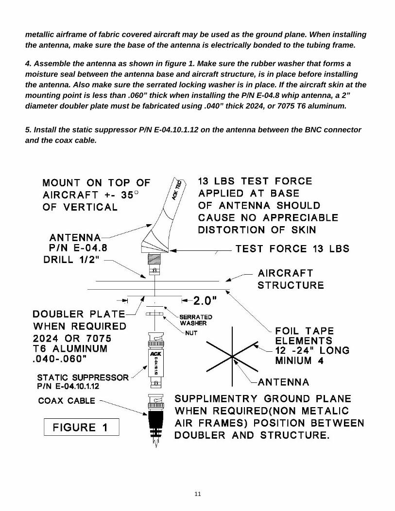
1. Drill a ½" (13mm) diameter hole in the aircraft at the antenna mounting location Figure 1 page 11.
2. Install the antenna, and determine if the antenna meets the static load requirements. If not, a doubler plate should be fabricated.
3. If the antenna is being mounted on a non conductive portion of the airframe, a supplementary ground plane must be installed. The supplemental ground plane must have a minimum diameter of 24" however 48” will provide maximum power at 121.5 MHz and is recommended. The ground plane must be centered around the base of the antenna. This may be fabricated out of copper, or aluminum tape. The tape should be cut into six elements 12" long, and the tape elements should be evenly spaced, radiating in a circular pattern from the base mounting point of the antenna. (Fig. 1) Make sure all elements are electrically bonded to the base of the antenna. The tape may follow the contour of the fuselage. The
11
metallic airframe of fabric covered aircraft may be used as the ground plane. When installing the antenna, make sure the base of the antenna is electrically bonded to the tubing frame.
4. Assemble the antenna as shown in figure 1. Make sure the rubber washer that forms a moisture seal between the antenna base and aircraft structure, is in place before installing the antenna. Also make sure the serrated locking washer is in place. If the aircraft skin at the mounting point is less than .060” thick when installing the P/N E-04.8 whip antenna, a 2” diameter doubler plate must be fabricated using .040” thick 2024, or 7075 T6 aluminum.
5. Install the static suppressor P/N E-04.10.1.12 on the antenna between the BNC connector and the coax cable.
12
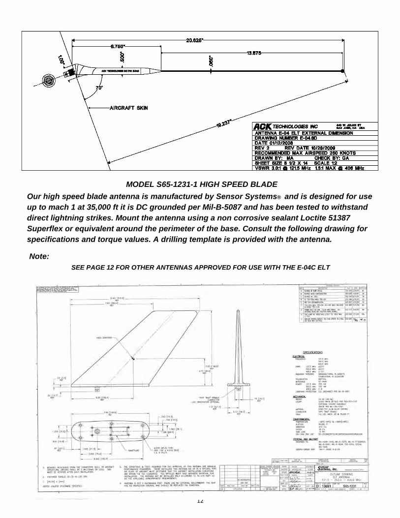
MODEL S65-1231-1 HIGH SPEED BLADE
Our high speed blade antenna is manufactured by Sensor Systems® and is designed for use up to mach 1 at 35,000 ft it is DC grounded per Mil-B-5087 and has been tested to withstand direct lightning strikes. Mount the antenna using a non corrosive sealant Loctite 51387 Superflex or equivalent around the perimeter of the base. Consult the following drawing for specifications and torque values. A drilling template is provided with the antenna.
Note: SEE PAGE 12 FOR OTHER ANTENNAS APPROVED FOR USE WITH THE E-04C ELT
13
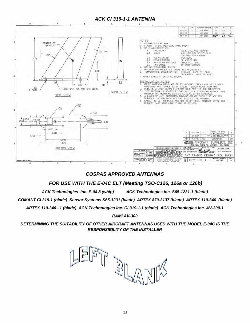
COSPAS APPROVED ANTENNAS
FOR USE WITH THE E-04C ELT (Meeting TSO-C126, 126a or 126b)
ACK Technologies Inc. E-04.8 (whip) ACK Technologies Inc. S65-1231-1 (blade)
COMANT CI 319-1 (blade) Sensor Systems S65-1231 (blade) ARTEX 870-3137 (blade) ARTEX 110-340 (blade)
ARTEX 110-340 –1 (blade) ACK Technologies Inc. CI 319-1-1 (blade) ACK Technologies Inc. AV-300-1
RAMI AV-300
DETERMINING THE SUITABILITY OF OTHER AIRCRAFT ANTENNAS USED WITH THE MODEL E-04C IS THE RESPONSIBILITY OF THE INSTALLER
ACK CI 319-1-1 ANTENNA
14
ACK AV-300-1 ANTENNA

15
Section 4
WIRING DIAGRAM

16
Section 5
HARNESS FABRICATION

17
Section 6
FINAL INSTALLATION
After installing the ELT and antenna in the aircraft, install the coaxial cable between the ELT transmitter and antenna base. If possible, the cable should not cross any production breaks in the airframe and must have a reasonable amount of slack at the transmitter. The slack is necessary for easy removal of the coaxial cable during maintenance. Secure the coaxial cable using tie wraps or other appropriate methods. Make sure the cable is protected from abrasion.
2.) The 8 pin plug should be fabricated on the bench using the color coding shown in figure 1 of section 5 page 16 of the manual. Prep the cable and crimp the pins on the cable as shown in figure 2 section 5 page 16 but do not insert them into the 15 pin plug until you have routed the cable. When the remote end of the cable is in the proper position insert them into the 15 pin plug using the color code guide shown in figure 3 of section 5. Avoid running this cable near sources of strong EMI/RFI radiation. (i.e. Comm cables, strobe light power cables, starter cables.) Secure the cable along its run using tie wraps or other suitable methods.
3.) After the installation and wiring is complete, verify that the ELT is receiving and processing positional data correctly. Apply power to both the ELT, and the navigational equipment supplying data. Make sure the navigational equipment has a satellite fix, and is reporting position data.
4.) Complete the steps in section 7 (registration) before you verify the installed operation of the ELT. After you have registered the ELT, do the self test as described in section 8 to verify the complete system is functioning properly.
8.) Record the ELT battery expiration date marked on the ELT battery case and the expiration date of the remote control battery, and record them in the aircraft records.
END

18
Section 7
REGISTRATION
1.) Before completing the final check out of the ELT, YOU MUST FIRST REGISTER YOUR BEACON FOLLOWING THE REGISTRATION REQUIREMENTS OF THE COUNTRY WHERE THE AIRCRAFT IS BASED. YOU CAN ONLY REGISTER THE ELT IN THE COUNTRY WHERE THE AIRCRAFT IS REGISTERED. If installing in US registered aircraft no programing of the ELT is required. If registering in a country other than the US the ELT need to be reprogramed. Our distributors have this capability or you may select on of our many authorized programing centers located world wide our website has a current list www.ackavionics.com .
2.) There is a preprinted self adhesive label supplied with the ELT which has the hex code, manufacturer, and model number on it. You should affix it to the top of the registration form or you can refer to this label when registering over the internet. You can download the registration forms for your country from our website.
WWW.ACKAVIONICS.COM
3.) In the U.S. and Canada you can mail or fax the registration forms, however it is strongly recommended that beacon registration be completed on line at the following sites:
UNITED STATES
www.beaconregistration.noaa.gov
CANADA
www.canadianbeaconregistry.forces.gc.ca
4.) For other countries contact the COSPAS/SARSAT regulating body for registration instructions. If allowed by your regulating country you may register at the
COSPAS/SARSAT website.
INTERNATIONAL
www.406registration.com
5.) When filling out the registration, the hex code identifier may also be found on the front right side of the ELT Figure 1.
6.) YOU MUST UPDATE YOUR BEACON REGISTRATION every two years and any time the beacon is used in a different aircraft.
Note: No letter “O” used in Hex codes, just zero's
19
Section 8
OPERATION AND SELF TEST
THERE ARE THREE MODES THAT THE ELT MAY BE ACTIVATED:
1.) The ELT automatically activates when in the “armed” position, and a crash level deceleration force (4.5FPS +/- .5 FPS) is applied to the ELT, in the forward direction as indicated by the arrow on the top of the battery pack.
2.) The ELT also may be activated by pressing the “On” button on the cockpit remote control Figure 1.
3.) A third method of activating the ELT, is by means of placing the main on-off-armed switch, on the front of the ELT in the “On” position.
The red rubber cover, covering the main switch on the ELT SHOULD BE LEFT OFF AT ALL TIMES, EXCEPT WHEN THE ELT IS IN THE ARMED POSITION. The cover has a center cone which projects down into the switch recess and provides for positive retention of the switch in the armed position.
There are two modes in which the ELT may be deactivated.
1.) Pressing the “Reset” button on the remote control Figure 1.
2.) Placing the main switch on the ELT in the “Off” position.
When the ELT is activated and transmitting the 406 MHz distress signal, the red cockpit remote led will flash and the audio alert indicator will emit a series of 9 beeps, approximately every 50 seconds to alert the crew that the ELT is operating. If there is no emergency, reset the ELT using the “Reset” button on the remote, and immediately notify the appropriate search and rescue operations office, or ATC of the false activation if 50 seconds or more have elapsed after the ELT was activated.
SELF TESTS:
The ELT is capable of performing a self test to verify that major ELT systems are functioning properly. When turning on the aircraft power allow at least 15 seconds before preforming the self test. When doing more than one self test allow at least 15 seconds between tests.
During the self test, the ELT transmits on 121.5 MHz for 1 second, (3 audio sweeps) then transmits a 406 MHz test burst for 550ms, then returns to the armed mode.
There are two modes in which a self test can be initiated:
1.) When the ELT is in the “Armed” position, pressing the “Reset/Test” switch on the cockpit remote control (RCPI) initiates a self test figure 1.
2.) When the main switch of the ELT is moved from the “Off” position to the “Armed” position, it does a self test. This mode is primarily designed to provide a method to bench test the ELT with the remote control disconnected.
YOU MUST PERFORM A SELF TEST EVERY FOUR MONTHS to verify the ELT is functioning properly.
20
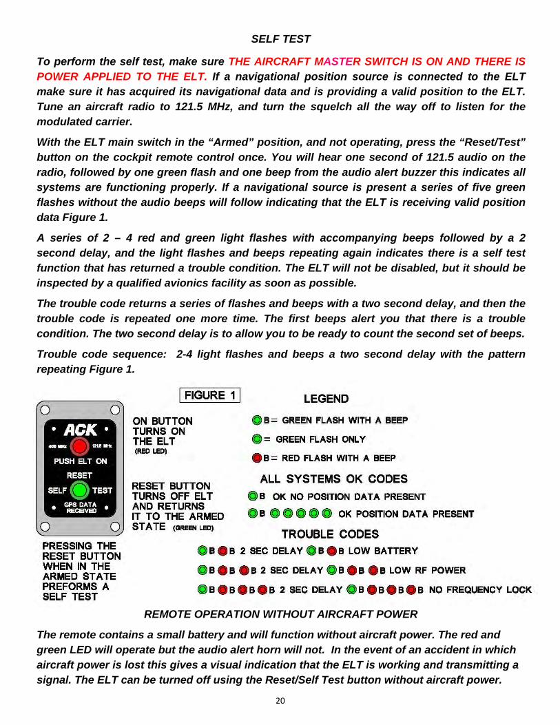
To perform the self test, make sure THE AIRCRAFT MASTER SWITCH IS ON AND THERE IS POWER APPLIED TO THE ELT. If a navigational position source is connected to the ELT make sure it has acquired its navigational data and is providing a valid position to the ELT. Tune an aircraft radio to 121.5 MHz, and turn the squelch all the way off to listen for the modulated carrier.
With the ELT main switch in the “Armed” position, and not operating, press the “Reset/Test” button on the cockpit remote control once. You will hear one second of 121.5 audio on the radio, followed by one green flash and one beep from the audio alert buzzer this indicates all systems are functioning properly. If a navigational source is present a series of five green flashes without the audio beeps will follow indicating that the ELT is receiving valid position data Figure 1.
A series of 2 – 4 red and green light flashes with accompanying beeps followed by a 2 second delay, and the light flashes and beeps repeating again indicates there is a self test function that has returned a trouble condition. The ELT will not be disabled, but it should be inspected by a qualified avionics facility as soon as possible.
The trouble code returns a series of flashes and beeps with a two second delay, and then the trouble code is repeated one more time. The first beeps alert you that there is a trouble condition. The two second delay is to allow you to be ready to count the second set of beeps.
Trouble code sequence: 2-4 light flashes and beeps a two second delay with the pattern repeating Figure 1.
SELF TEST
REMOTE OPERATION WITHOUT AIRCRAFT POWER
The remote contains a small battery and will function without aircraft power. The red and green LED will operate but the audio alert horn will not. In the event of an accident in which aircraft power is lost this gives a visual indication that the ELT is working and transmitting a signal. The ELT can be turned off using the Reset/Self Test button without aircraft power.

21
Section 9
BATTERY REPLACEMENT E-01.0 MAIN BATTERY
The lithium battery (P/N E-04.0) must be replaced on, or before the battery expiration date marked on the battery. It is no longer airworthy after this date. The battery must be replaced if more than 1 hour of cumulative use has occurred. See FAR 91.207 for this and other ELT requirements. TSO-C142a REQUIRES THE BATTERY PACK BE SEALED AND PROHIBITS REPLACING INDIVIDUAL CELLS IN THE BATTERY PACK.
1.) Using a 3/32 hex wrench, remove the four retaining screws that attach the battery case to the ELT transmitter assembly, and gently pull the battery pack from the transmitter section. (Page 22 Fig. 3)
2.) WITH THE MAIN SWITCH IN THE “OFF” POSITION, install the new sealed battery pack.
(P/N E-04.0) The battery pack is designed so the battery can only be installed in the proper orientation. Wet the O-ring with a mild dish soap solution, and shake off the excess solution, or use silicon vacuum grease. Install the O-ring onto the battery case. Remove the two protective caps from the battery contacts. (Page 22 Fig. 2) The battery pack should slide easily into the transmitter housing.
3.) Re-attach the transmitter assembly to the battery pack by replacing the four hex head screws. Tighten the screws to 3.5-4.0 in-lbs.
4.) Record the new battery expiration date in the airframe logbook.
5.) After re-installation of the ELT into the aircraft, a self test must be performed. Refer to section 8.
THE FOLLOWING IS AN EXCERPT FROM FAA AC 91-44A PARAGRAPH 8.a WHICH DEFINES WHEN ELT BATTERY REPLACEMENT MAY BE DONE UNDER 14 CFR PART
43.3(h) AS PREVENTIVE MAINTENANCE.
“…The replacement can be done by the pilot if the preventive maintenance limitations of part 43.3(h) of the FAR, are complied with. For example, a portable type ELT that is readily accessible and can be removed and reinstalled in the aircraft by a simple operation should be considered preventive maintenance. Fixed type ELT installations are often permanently mounted in a remote area of the aircraft near flight control cables, vital aircraft components, and critical attachments to the aircraft structure. Installations of this nature require an external antenna and often a remote on/off transmitter control switch that is usually located near the pilots flight position. This type of installation is complex and battery replacement should be accomplished by a certified mechanic or certified repair station…”
BATTERY AND ELT DOT/ IATA SHIPPING INFORMATION
The ELT with the battery attached is a DOT/IATA class 9 hazmat material under the
category of life saving appliances not self inflating UN 3072. The battery by itself is DOT/IATA Class 9 UN 3090. Follow all DOT and IATA regulations when shipping the ELT or ELT battery.
22
REMOVE
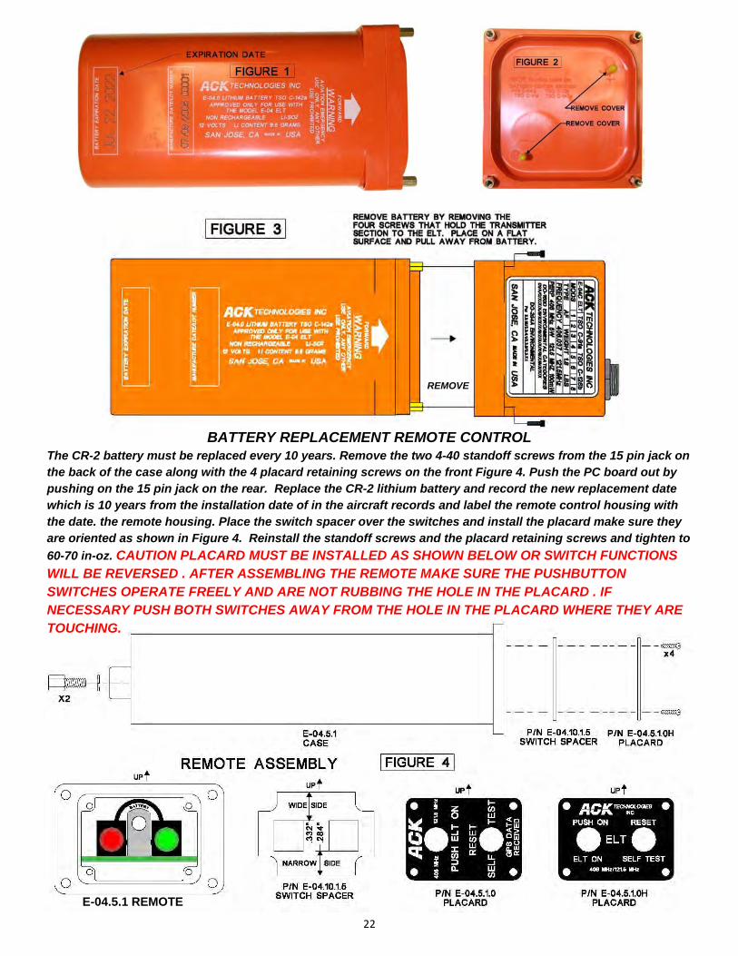
BATTERY REPLACEMENT REMOTE CONTROL The CR-2 battery must be replaced every 10 years. Remove the two 4-40 standoff screws from the 15 pin jack on the back of the case along with the 4 placard retaining screws on the front Figure 4. Push the PC board out by pushing on the 15 pin jack on the rear. Replace the CR-2 lithium battery and record the new replacement date which is 10 years from the installation date of in the aircraft records and label the remote control housing with the date. the remote housing. Place the switch spacer over the switches and install the placard make sure they are oriented as shown in Figure 4. Reinstall the standoff screws and the placard retaining screws and tighten to
60-70 in-oz. CAUTION PLACARD MUST BE INSTALLED AS SHOWN BELOW OR SWITCH FUNCTIONS WILL BE REVERSED . AFTER ASSEMBLING THE REMOTE MAKE SURE THE PUSHBUTTON SWITCHES OPERATE FREELY AND ARE NOT RUBBING THE HOLE IN THE PLACARD . IF NECESSARY PUSH BOTH SWITCHES AWAY FROM THE HOLE IN THE PLACARD WHERE THEY ARE TOUCHING.
E-04.5.1 REMOTE

23
Section 10
PERIODIC MAINTENANCE/CONTINUING AIRWORTHINESS
THE FOLLOWING TEST MUST BE PERFORMED EVERY FOUR CALENDAR MONTHS.
ELT SELF TEST FUNCTION AS DESCRIBED IN SECTION 8 OF THIS MANUAL.
THE FOLLOWING TESTS MUST BE PERFORMED A MINIMUM OF EVERY TWELVE CALENDAR MONTHS, TO ASSURE THE CONTINUING AIRWORTHINESS OF THE ELT.
1.) Inspect the ELT transmitter and mounting tray to insure all fasteners and mechanical assemblies are secure.
2.) Inspect the coaxial cable connecting the ELT transmitter to the antenna for cuts or abrasions on its outer jacket. Disconnect the BNC connector at each end. Examine both BNC connectors and the mating plug on the ELT transmitter and antenna base for any signs of corrosion.
3.) Inspect the cable connecting the ELT to the remote unit for signs of wear or abrasion on its outer jacket. Remove the circular plug connecting the ELT transmitter to the connecting cable, and inspect the jack and plug assembly for corrosion.
4.) Check the expiration date of the remote battery and audio alert battery in the aircraft log book. Check the expiration date marked the battery pack and replace if necessary.
5.) Leave the ELT in the “Armed” position, then remove the ELT from the aircraft, and perform a G switch test as follows:
This test should be conducted between the hour and 5 minutes after the hour per FCC requirements. Tune an aircraft radio, or hand held aircraft radio to 121.5 MHz. The radio should be in close proximity to the area where you will conduct the test.
TURN THE SQUELCH CONTROL ALL THE WAY DOWN, OR OFF. You should be hearing white noise on the radio. If switching the main switch from the “Off” to the “Armed” position wait at least 15 seconds before performing this test. While in the “Armed” position, hold the ELT at your waist with the arrow printed on the battery case facing away from you. Move the ELT rapidly away from your waist. When the ELT reaches the full extent of your arm, retract it back to your waist as fast as possible. You should hear the 121.5 MHz sweep tone in the radio. AS SOON AS YOU HEAR THE TONE, IMMEDIATELY TURN THE MAIN SWITCH ON THE ELT TO THE “OFF” POSITION.
The ELT when activated transmits on 121.5 MHz for approximately 50 seconds before a 406 MHz burst is sent to the satellites. This is a live burst which will immediately notify the COSPAS/SARSAT system that there is an emergency. IT IS IMPERATIVE THAT YOU DO NOT ALLOW AN ACTIVATED ELT TO TRANSMIT FOR MORE THAN 30 SECONDS DURING G SWITCH TESTING.
7.) Reinstall the ELT. Make sure the cables are secured and properly connected. Place the main switch in the “Armed” position, and install the rubber cover over the main switch opening.
8.) Perform the self test described in section 8 to verify proper operation.

24
Section 11
CANADIAN MAINTENANCE REQUIREMENTS
In addition to our periodic maintenance requirements of section 10 In Canada you must comply with CAR part 5, chapter 571, appendix G maintenance requirements for continued airworthiness. We strongly recommend the WS technologies Inc BT100AV, or BT100AVS tester if available be used to verify the performance characteristics of the ELT.
WEBSITE: WWW.WST.CA
THESE TESTS SHOULD ONLY BE PERFORMED IN A RF SCREEN ROOM.
When using conventional test equipment to perform this test:
Connect the RF output of the ELT to a spectrum analyzer with a 50 ohm impedance capable of measuring frequency and power, and perform the following tests. THE OUTPUT POWER DURING THE 406 MHz BURST IS + 37 dBm MAKE SURE THIS DOES NOT EXCEED THE MAXIMUM INPUT LEVEL OF THE ANALYZER. An attenuator may be necessary to reduce the input power to the analyzer. The test results must fall within the following minimum and maximum values:
406 FREQUENCY: 406.037000 MHz +/- 2 kHz
POWER: +35 to +39 dBm
121.5 MHz FREQUENCY: 121.5 MHz +/- 6 kHz
POWER: + 17 to +23 dBm
The current draw requirements of the regulations may be confirmed by removing the battery case, separating it from the transmitter head and using jumpers to connect the battery in series with the current meter.
CAUTION: THE POWER INPUT IS NOT PROTECTED FROM REVERSE POLARITY. IF REVERSE POLARITY IS APPLIED SEVERE DAMAGE WILL OCCUR AND VOID THE WARRANTY.
STANDBY CURRENT IN THE ARMED MODE: 30 uA ≤=
Preform the G switch activation required by CAR PART 5, CHAPTER 571, APPENDIX G Paragraph (c) (3) (e) by following the procedures in section 10 on page 20 of this manual.

25
APPROVALS:
FAA / TRANSPORT CANADA
TSO -C126b TSO-C91a TSO-C142a
EASA
ETSO 2C126 ETSO 2C91a TSO-C142a
INDUSTRY CANADA
1863A-E04AF
BRAZIL ANAC/ANTEL
TSO-C126 TSO-C142a
TYPE:
TSO-C126b TSO-C91a AF
FREQUENCY:
121.5 MHz & 406.037 MHz
MODULATION:
406 MHz +/-2 kHz Bi-Phase L (16KOG1D)
121.5 MHz +- 6 kHz AM (3K20A3N)
SWEPT DOWNWARD 1400 – 400 Hz
REPETITION RATE 3 Hz
MODULATION FACTOR ≥ 90%
DUTY CYCLE ≥ 45%
POWER AT TERMINAL 50 Ω LOAD:
121.5 MHz 20.7 dBm 50 HOURS@ -20C
406.037 MHz 37.3 dBm 24.5 HOURS @ -20C
PEAK EIRP WITH E-04.8 WHIP ANTENNA AND E-04.10.4 COAX CABLE: 121.5 MHz +21 dBm 125 mW
406.037 MHz +39.79 dBm 13.7 W
PEAK EIRP WITH S65-1231 BLADE ANTENNA AND E-04.10.4 COAX CABLE:
121.5 MHz +23 dBm 200 mW
406.037 MHz +39.79 dBm 13.7 W
OPERATING TEMPERATURE:
-20C TO +55C
STORAGE TEMPERATURE:
-55C TO +85C
CRASH ACTIVATION:
4.5 FpS +- .5 FpS
DIMENSIONS:
7.750” x 2.850” x 2.850”
192 mm x 72 mm x 72 mm
WEIGHT:
ELT AND BATTERY PACK 1.6 lbs .73kg
ELT TRAY AND STRAPS .2 lbs .09kg
REMOTE CONTROL 2.5oz 71g
AUDIO HORN 0.4 oz 11g
WHIP ANTENNA ACK PART NUMBER E-04.8
LENGTH 20.625” 524 mm SWEPT 20º
WEIGHT 2.1 oz 60g
IMPEDANCE 50 OHM NOMINAL
VSWR @ 121.5 MHz ≤ 3.0:1
VSWR @ 406 MHz ≤ 1.5:1
MAXIMUM RECOMMENDED AIRSPEED 260 KNOTS@ SEA LEVEL
BLADE ANTENNA ACK PART NUMBER S65-1231-1
HEIGHT 7.5” 190 mm SWEPT 20º
WEIGHT 23 oz 652g
IMPEDANCE 50 OHM NOMINAL
VSWR @ 121.5 MHz ≤ 2:1
VSWR @ 406 MHz ≤= 1.5:1
MAXIMUM RECOMMENDED AIRSPEED MACH 1 @ 35,000 Ft
SECTION 12
SPECIFICATIONS

26
APPROVALS:
FAA / TRANSPORT CANADA
TSO-C142a
ETSO-C142a
BRAZIL ANAC TSO-C142a
UN/DOT 38.3
TYPE:
Li-SO2
NON FLAMMABLE ELECTROLYTE
VOLTAGE:
12 VOLTS
DIMENSIONS:
5.750” x 2.850” x 2.850”
146mm x 72mm x 72mm
WEIGHT:
1.18 lbs .535 kg
OPERATING TEMPERATURE:
-20C TO +55C
AMP HOUR RATING:
7.75 Ah
NON RECHARGEABLE
LITHIUM CONTENT:
9.8 GRAMS
MAXIMUM DISCHARGE RATE:
2.5 AMPS
BATTERY LIFE:
5 YEARS WHEN USED WITH THE MODEL
E-04 ELT
MODEL E‐04.0 LITHIUM BATTERY SPECIFICATIONS
LIMITATIONS: ANY OTHER USE OF THIS BATTERY IN AIRCRAFT IS PROHIBITED UNLESS APPROVED BY
ACK TECHNOLOGIES INC.
THE CONDITIONS AND TESTS FOR TSO APPROVAL OF THIS ARTICLE ARE MINIMUM PERFORMANCE STANDARDS. THOSE INSTALLING THIS ARTICLE, ON OR IN A SPECIFIC TYPE OR CLASS OF AIRCRAFT, MUST DETERMINE THAT THE AIRCRAFT INSTALLATION CONDITIONS ARE WITHIN THE TSO STANDARDS. TSO ARTICLES MUST HAVE SEPARATE APPROVAL FOR INSTALLATION IN AN AIRCRAFT. THE ARTICLE MAY BE INSTALLED ONLY ACCORDING TO 14 CFR PART 43 OR THE APPLICABLE AIRWORTHINESS REQUIRE-MENTS. LITHIUM CELL AND BATTERY SAFETY CONCERNS INCLUDE THE POSSIBILITY OF FIRE AND VENT-ING OF TOXIC GASES
27
Section 13
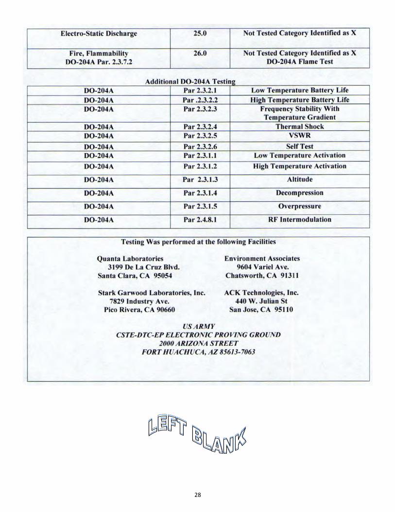
28
29
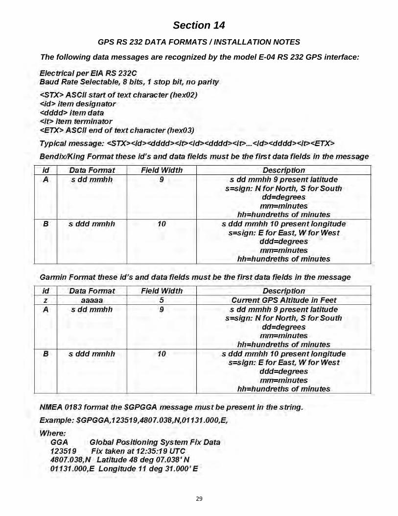
Section 14
GPS RS 232 DATA FORMATS / INSTALLATION NOTES
The following data messages are recognized by the model E-04 RS 232 GPS interface:
30
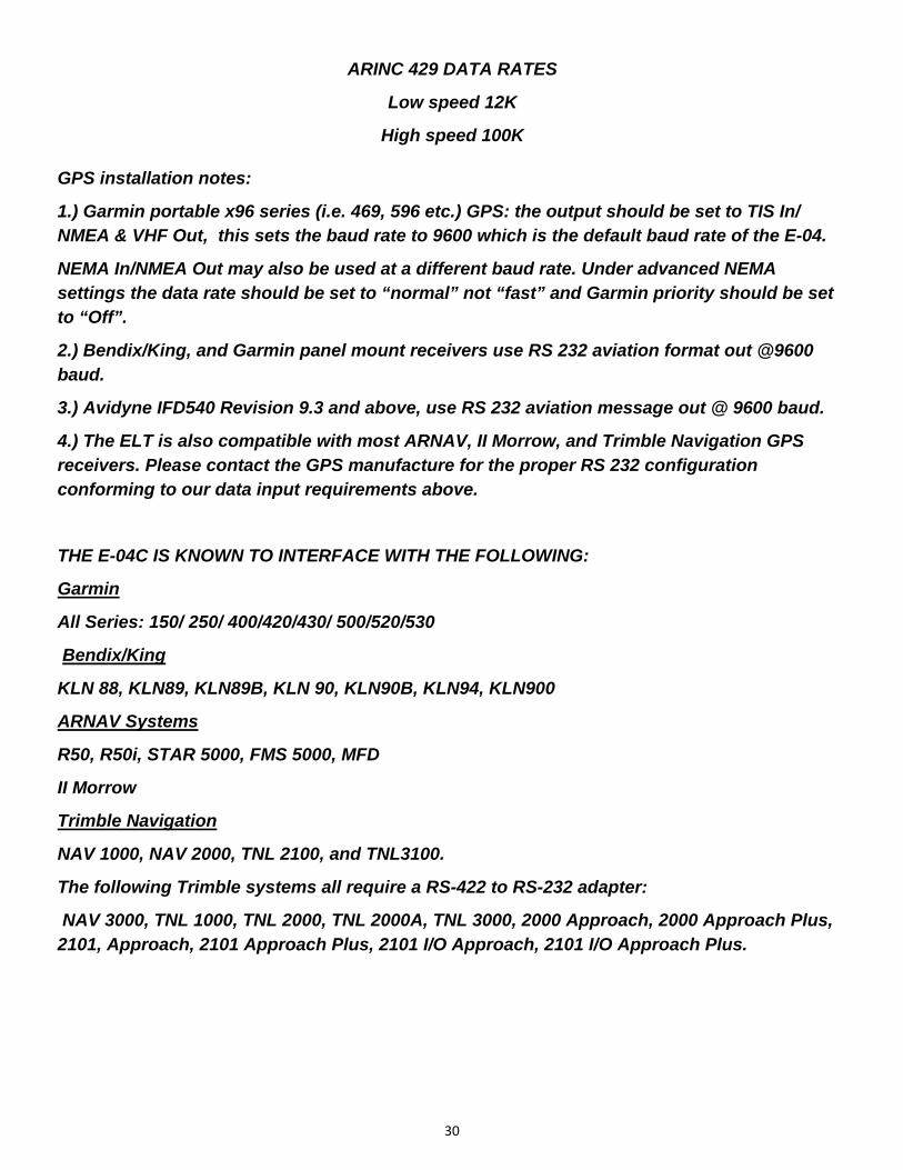
GPS installation notes:
1.) Garmin portable x96 series (i.e. 469, 596 etc.) GPS: the output should be set to TIS In/NMEA & VHF Out, this sets the baud rate to 9600 which is the default baud rate of the E-04.
NEMA In/NMEA Out may also be used at a different baud rate. Under advanced NEMA settings the data rate should be set to “normal” not “fast” and Garmin priority should be set to “Off”.
2.) Bendix/King, and Garmin panel mount receivers use RS 232 aviation format out @9600 baud.
3.) Avidyne IFD540 Revision 9.3 and above, use RS 232 aviation message out @ 9600 baud.
4.) The ELT is also compatible with most ARNAV, II Morrow, and Trimble Navigation GPS receivers. Please contact the GPS manufacture for the proper RS 232 configuration conforming to our data input requirements above.
THE E-04C IS KNOWN TO INTERFACE WITH THE FOLLOWING:
Garmin
All Series: 150/ 250/ 400/420/430/ 500/520/530
Bendix/King
KLN 88, KLN89, KLN89B, KLN 90, KLN90B, KLN94, KLN900
ARNAV Systems
R50, R50i, STAR 5000, FMS 5000, MFD
II Morrow
Trimble Navigation
NAV 1000, NAV 2000, TNL 2100, and TNL3100.
The following Trimble systems all require a RS-422 to RS-232 adapter:
NAV 3000, TNL 1000, TNL 2000, TNL 2000A, TNL 3000, 2000 Approach, 2000 Approach Plus, 2101, Approach, 2101 Approach Plus, 2101 I/O Approach, 2101 I/O Approach Plus.
ARINC 429 DATA RATES
Low speed 12K
High speed 100K

31
Section 15
MAJOR PARTS

32
Section 16
LIMITED WARRANTY
THIS MODEL E-04 EMERGENCY LOCATOR TRANSMITTER IS GUARANTEED BY ACK TECHNOLOGIES, INC. AGAINST DEFECTS IN MATERIALS AND WORKMANSHIP FOR A PERIOD OF TWO YEARS FROM THE INSTALLATION DATE OR TWO YEARS THREE MONTHS FROM THE DATE IT WAS MANUFACTURED WHICHEVER OCCURS FIRST. THIS WARRANTY IS LIMITED EXCLUSIVELY TO REPAIR OR REPLACEMENT OF THE E-04 ELT AND ASSOCIATED PARTS WHICH WERE MANUFACTURED BY ACK TECHNOLOGIES, INC. THE DEFECTIVE PARTS MUST BE RETURNED FREIGHT PREPAID TO OUR MANUFACTURING FACILITY. THIS WARRANTY DOES NOT INCLUDE REPAIR OR REPLACEMENT OF ANY PART THAT HAS BEEN IMPROPERLY USED, INSTALLED OR PHYSICALLY DAMAGED. THIS WARRANTY DOES NOT COVER ANY DAMAGE CAUSED BY CHEMICAL EXPOSURE TO THE ELT. DISCHARGE OF THE LITHIUM BATTERY IS NOT COVERED BY THIS OR ANY OTHER WARRANTY. EXCEPT AS PROVIDED HEREIN ACK TECHNOLOGIES, INC. MAKES NO EXPRESS WARRANTIES, AND ANY IMPLEMENTED WARRANTY OF MERCHANTABILITY OF FITNESS FOR A PARTICULAR PURPOSE IS LIMITED IN ITS DURATION TO THE DURATION OF THE WRITTEN LIMITED WARRANTIES SET FORTH HEREIN. ACK TECHNOLOGIES, INC. SHALL NOT BE LIABLE FOR ANY DIRECT, INDIRECT, SPECIAL OR CONSEQUENTIAL DAMAGES ARISING FROM THE USE OR MISUSE OF THIS PRODUCT. EXCEPT AS PROVIDED HEREIN NO EMPLOYEE, AGENT, DEALER, OR OTHER PERSON IS AUTHORIZED TO GIVE ANY WARRANTIES OF ANY NATURE ON BEHALF OF ACK TECHNOLOGIES, INC.
YOU MAY HAVE ADDITIONAL LEGAL RIGHTS WHICH VARY FROM STATE TO STATE
WARRANTY PROCEDURE
Should it become necessary to return the ELT for warranty service send the transmitter section only. REMOVE THE ELT BATTERY BEFORE SHIPPING THE UNIT TO OUR FACILITY. All units must be returned to our facility freight prepaid. Our shipping Address is as follows:
ACK TECHNOLOGIES, INC.
440 W. JULIAN ST.
SAN JOSE, CA 95110
Make sure that you have included paperwork with a return address that Is suitable for UPS return shipment. (no PO boxes, or APO numbers) Please include a short description of the problem you have been experiencing, and a telephone number where you may be reached during business hours. No RMA number is required.
Any unit that is returned for warranty, and found not to be defective will be charged a minimum handling and service charge, and returned C.O.D.


