Manual Power Factor Controller - Janitza Prophi® 7 6 Prophi® 7 Section 2 Installation and...
35
Doc no. 2.020.009.0 - Version 2.0 - E - May 2014 Janitza electronics GmbH Vor dem Polstück 1 D-35633 Lahnau Support tel. +49 (0) 64 41 9642-22 Fax +49 (0) 64 41 9642-30 e-mail: [email protected] Website: http://www.janitza.com www.janitza.com Manual Power Factor Controller Prophi ® 7-1
Transcript of Manual Power Factor Controller - Janitza Prophi® 7 6 Prophi® 7 Section 2 Installation and...

Doc
no.
2.0
20.0
09.0
-
Ver
sion
2.0
- E
-
May
201
4
Janitza electronics GmbHVor dem Polstück 1D-35633 LahnauSupport tel. +49 (0) 64 41 9642-22Fax +49 (0) 64 41 9642-30e-mail: [email protected]: http://www.janitza.com
ww
w.ja
nit
za.c
om
Manual
Power Factor Controller
Prophi®7-1
ManualVersion 2.0 - E
Version 2.0 E, May 2014
Power Factor ControllerProphi7-1 (/S485)
rellortnoc rotcaf re
wop
noitareneg txe
n

Prophi® 72
Prophi® 7
!
CAUTIONS:
1. High voltage !2. The device may only be used indoor !3. Make sure that the discharge time set in controller matches capacitor discharge time !
UNDERCOMPENSATED------------------
------------------
------------------
Q-Diff= 82kvar
U
I
Q
1 2 3 4 5 6 7 8 9
223.0 V
268 A
107 kvar
HARMONICS [V]
2 3 4 5 6 7 8 9 10 11 12 13 14 15 16 17
2.0%
1.0%
0%
AUTO-MODE
ERROR MESSAGE
DISPLAY-MODE
BARGRAPH-MODE
10 11 12 A M
AUTO MODE------------------
cos 0.987 IND
1 2 3 4 5 6 7 8 9 10 11 12 A M
j

Prophi® 73
Prophi® 7
CONTENTS
Section 1 General / type series and accessories 4
Section 2 Installation of the controller / connection diagram 6
2.1 Current measurement 72.2 Programming of phase-correction2.3 Error messages: Alarm- / Message relay 8
Section 3 Operating modes 8
Section 4 Automatic operation / display functions 9
Section 5 Programming5.1 Automatic initialization 105.2 Manual programming 115.3 Programming lock 14
Section 6 Manual operation / Programming of fixed stages 15
Section 7 Service menu, Test run 16
Section 8 Expert mode 178.1 Expert mode 18.2 Expert mode 2 19
Section 9 Control principle 20
Section 10 Display editor 21
Section 11 Initial operation 21
Section 12 Maintenance and warranty 21
Section 13 Interface (only version .../S485) 22
Annex: Annex 1 Troubleshouting 24Annex 2 Technical data 25Annex 3 Table of control series 26
Description of control-series editorAnnex 4 Default settings 27
Application Mixed dynamic compensation 29Cascading of controllers
Application Real current measurement 30
Alarm and status notifications 31Handling-diagram / short reference 32
Application Coupling of compensation systems 28
- 2 -

Prophi® 74
Prophi® 7
Section1 General
The power factor controller Prophi7-1 (single phase) enlarges the product range of power factor control devices by a useful combination of the features known from the well-proven series with the advantages of a better visualization.
The big graphic display enables a user-friendly programming and gives further benefits such as larger display in the Display-mode and the display of various parameters in bargraph-mode.
With the additional “ESCAPE”-button a backward navigation in all menus is possible.
The “HELP”-button allows an interactive help in the particular menu item (German/English).
The controller is characterized by its user friendly operating interface via menu driven plain text display. The display of several grid parameters, the storage of different values as well as the possibility of test run allow a simple error analysis and system monitoring.
If required, an automatic initialization is possible which reduces the start-up operation to a minimum.
R 12 respectively 13 switching outputsR 20 pre-programmed control series with self optimized intelligent control behaviorR Control series editor for individual control seriesR Operation and display completely menu-drivenR Illuminated graphic display 128 x 64 dotsR 4 quadrant operationR Automatic initialization possibleR Display of several grid parameters also in large lettersR Display of harmonics of voltage and current, also as bar diagramR Display and monitoring of temperatureR Monitoring of the particular capacitor outputR Storage of maximum values of grid parameters as well as switching operations
and switch-in times of particular capacitor contactorsR Manual/automatic operationR Programming of fixed steps or skipping of single outputs possibleR Zero voltage switch offR Error display of different states and alarm output (relay)R Error storageR Test run of the system with error analysisR Panel-mounted instrument 144 x 144 x 53 mmR Firmware update possible
Version with interface only:
R additional external input (function programmable), e.g. for 2nd parameter setR additional freely programmable alarm relay, e.g. for fan, status notificationR serial interface RS485, for controller coupling, integration into networksR visualization, programming and data processing via PC by enclosed software
- 3 -

Prophi® 75
Prophi® 7
The controller is supplied as standard for an operating voltage of 110...230 VAC (+-15%), a measuring voltage of 30...440 V~ (L-N) resp. 50...760V~(L-L) and a measuring current of 5A or 1A. A voltage converter is required for different operating voltages.
Caution!Voltages which exceed the specified voltage range can damage the device !
- 4 -
!
Operating mode:- Automatic- Program.- Manual oper.- Service- Expert Mode- Osci - Mode- Display Editor
ENTER/ OKConfirmationstorage ofvalues
Increaseselected parameter
HELPopens
Help pages
Reduceselectedparameter
Escapeprevious
page/valuein the display
Front view
HELP
ESC
Rear view
P1 P2K1 K7K2 K8K3 K9K4 K10 K11 K12 K13K5 K6
L N L1(L3)
N (L2)
k l
supply voltage meas. voltage meas. current
alarmrelay
POWER FACTOR CONTROLLERProphi 7-I
L1 (R)
L2 (S)
L3 (T)
N
1. capacitor-branch
k l
P1 P2
1 2 3 4 5 6 7 8 9 10 11 12
capacitor-contactors 1-6
alarm-relay
capacitor-contactors 7-12
T 6
,3A
T 2
A
T 2
A
PE
K1
13
L N L1 N k l
Ser.No.:
MADE IN GERMANY
meas. voltage:30-440V(L-N),50-760V(L-L)
supply voltage: 110...230VAC 50/60Hz
Type: Prophi 7-1
meas. currentIm (5A/1A)
supply-voltage Vb
meas. voltage Vm

Prophi® 76
Prophi® 7
Section 2 Installation and connection of the controller
The controller is designed to be incorporated into the front panel of a PFC-cabinet. It requires a switchboard section of 138 x 138 mm to DIN 43700/ IEC 61554. The controller is inserted from the front and is attached by means of the appended clamps. The controller may be inserted only by qualified technicians and must be operated in accordance with the specified safety regulations.Before the device is connected up, all leads and cables must be checked to ensure that no current is flowing through them and the current converter must be short-circuited. Care should be taken to ensure that the measuring voltage and current are in the correct phase
2position. The measuring-current circuit must be wired with copper leads of 2.5mm . The connection should be set up as shown below. The specified safety regulations must be observed.
The measuring voltage may lie in the range from 30...440 V~ (L-N) resp. 50..760V~ (L-L) (programming of phase correction needed)
The operating voltage is 110...230 VAC +/- 15%.
The coil voltage for the capacitor contactors and the measuring voltage must be drawn from the same phase conductor, as only the measuring voltage is monitored. (Protection against direct reconnection of the capacitor contactors in the event of momentary single-phase power failure)
Connection plan
- 5 -
L1 (R)
L2 (S)
L3 (T)
N
meas.currentIm (5A/1A)
1. capacitorbranch
supplyvoltage
Vb
meas.voltage
Vm k l
P1 P2
1 2 3 4 5 6 7 8 9 10 11 12
capacitorcontactors 1-6
alarmrelay
capacitorcontactors 7-12
power factorcontroller
T 6
,3A
T 2
A
T 2
A
PE
K1
a b
Ub Um Im
(L) (N) L1 N k l
(L3) (L2)
Power feed Load side
!
Prophi® 77
Prophi® 7
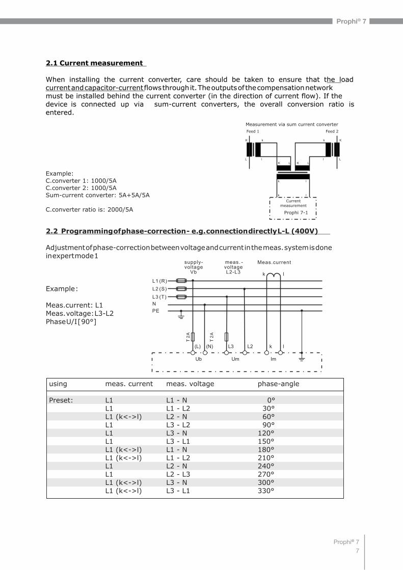
2.1 Current measurement
When installing the current converter, care should be taken to ensure that the load current and capacitor-current flows through it. The outputs of the compensation network must be installed behind the current converter (in the direction of current flow). If the device is connected up via sum-current converters, the overall conversion ratio is entered.
2.2 Programming of phase-correction - e.g. connection directly L-L (400V)
Adjustment of phase-correction between voltage and current in the meas. system is done in expert mode 1
Example :
Meas.current: L1Meas. voltage: L3-L2Phase U/I [ 90°]
- 6 -
L1 (R)
L2 (S)
L3 (T)
N
Meas.currentsupply-voltage Vb
meas. -voltage L2-L3 k l
T 2
A
T 2
A
PE
Ub Um Im
(L) (N) L3 L2 k l
using meas. current meas. voltage phase-angle
Preset: L1 L1 - N 0°L1 L1 - L2 30°L1 (k<->l) L2 - N 60°L1 L3 - L2 90°L1 L3 - N 120°L1 L3 - L1 150°L1 (k<->l) L1 - N 180°L1 (k<->l) L1 - L2 210°L1 L2 - N 240°L1 L2 - L3 270°L1 (k<->l) L3 - N 300°L1 (k<->l) L3 - L1 330°
kK k K
lL l L
Feed 1 Feed 2
K L K L
Measurement via sum current converter
Prophi 7-1
Currentmeasurement
k l
k l
Example:C.converter 1: 1000/5AC.converter 2: 1000/5ASum-current converter: 5A+5A/5A
C.converter ratio is: 2000/5A

Prophi® 78
Prophi® 7
Display-Mode Harmonics as bar-diagram
Active capacitorbranches
Control direction(here connected-in)
Supply display (for 4-quadrant operation)
The control direction is symbolizedby a closed arrow
The connecting-in arrow is alwayslocated after the maximum possiblenumber of stages (end stop)
An open arrow indicates that the required blocking time (dischargetime) is running before an impending switching step
A double arrow symbolizes fast switching of several branches
Connecting-inConnecting-out
By pressing the cursor buttons, the display of capacitor stages can be changed:
AUTO MODE------------------
cos 0.987 IND
1 2 3 4 5 6 7 8 9 10 11 12
j
------------------
------------------
U HARMONICS [V]
I
Q 2 3 4 5 6 7 8 9 10 11 12 13 14 15 16 17
223.0 V
268 A
107 kvar
2.0%
1.0%
0%
By activating the ENTER-button the selected display can be stored as standard main display.
2.3 Error-Messages: Alarmrelay / Message-relay*
The controller is equipped with an alarm relay. Version /S485 features an additional message relay. The functions may be programmed as follows:
Alarm relay: Setting under Message relay: Setting under Remark Programming: 14 Alarm relay INTERFACE: 1 MESSAGE RELAY
0 13th step Alarm relay=13.th step 1 OFF OFF 2 ERROR ERROR ERROR-summary report 3 ERROR inverse ERROR inverse List of errors in ExpertMode 2 4 FAN FAN ERROR:relay closed in case of error 5 Supply Supply ERROR inverse (factory setting): 6 Undercurrent Undercurrent contact open in case of error 7 Harmonics Harmonics 8 Overcompensated Overcompensated 9 Undercompensated Undercompensated 10 Warning switch. oper. Warning switch. oper. 11 Modbus-Error Modbus-Error 12 MMI-Error MMI-Error 13 C-defect C-defect 14 Fixed step OUT ext. input triggers fixed step
Adjustment and masking of all ERRORS is possible in the ExpertMode 2. The adjustment is valid for both relays.
Section 3: Operating modes
When the operating voltage is switched on, the device briefly displays its designation and software version, then changes to its normal operating status (automatic operation). The active cos-phi value is always displayed in the upper line and the currently connected capacitors are shown as sympols.
further messages compare last coverpage !

Prophi® 79
Prophi® 7
Section 4 Automatic operation - display of network parameter
The controller is set to automatic operation as standard (not AUTO-INIT). Capacitor stages are then automatically connected in or out in order to reach the target power factor. This happens if the required reactive power is approx. 1/3 higher than the value of the smallest capacitor step.In automatic operation, various network parameters can be displayed by repeatedly pressing the "ENTER” key:
Action Display
ENTER 1 LINE VOLTAGE in V /% ENTER 2 APPARENT CURRENT in A /% ENTER 3 REACTIVE POWER in kvar /% ENTER 4 ACTIVE POWER in kW /% ENTER 5 APPARENT POWER in kVA /% ENTER 6 DIFF. kVAR TO TARGET COS ENTER 7 FREQUENCY in Hz ENTER 8 TEMPERATURE in °C / °F ENTER 9 HARMONICS V / %, I / %
Selection via arrow-keys ENTER 10 HARMONICS THD-V/%, THD-I/% 11 Compensation power in kvarENTER 12 ENERGY
(kWh, kvarh, consumption, delivery) reset in: service / max.value reset
ENTER Software version ENTER Return to: 1
The power value specifies the total power (3-phase) assuming symmetrical load. If no key is pressed for 120 seconds, the display automatically returns to the operating status!
Under “13 Date-Time” the date format 12h/24h setting can be changed by the arrow buttons (only version /S).
ENTER
ENTER 13 DATE - TIME
Repeated pressing of the "Operating Mode” key takes the user to the various menus:
- 8 -
Auto operation Programming
Expert Mode 2
Manual operat.
Display-Editor back to 1
Service
Expert Mode 1
AUTO-MODE------------------
AUTO-MODE------------------
3 REACTIVE POWER
118 kvar
10 HARMONICS THD rel.
V 1.7% I 0.8%
INTERFACE

Prophi® 710
Prophi® 7
5.1. Automatic initialization
With the automatic initialization the device will automatically recognize the parameters of the PFC-system. It also serves as plausibility check and storage of these parameters - the user only has to make very little or even no adjustments.Start of the initialization process is done from the menu point “PROGRAMMING” by pressing the button “ ”AUTO-INIT [YES] to be confirmed with pressing the ENTER button.
Now either the values of the current transformer OR the value of the smallest step of the system have to be keyed in. The input of one of these values is absolutely mandatory. After input (confirm with ENTER) the automatic test run of the controller is executed.
é
3 test-runs will be performed during which all stages are being switched on and off. All necessary parameters are collected, evaluated and stored. Under certain circumstances 3 additional test-runs may be required for a proper initialization.After successful finalization of AUTO-INIT the controller will switch to normal operation.
In case of recognition of any discrepancies (plausibility) or of inaccurate connection, the detected error will be displayed in plain text after finalization of AUTO-INIT and can be eliminated. (see possible error messages at the end of the manual). AUTO-INIT may be repeated then.
- 9 -
AUTO-INIT------------------
AUTO-INIT------------------
AUTO-INIT------------------
1 CURRENT TRANSF.
[ UNKNOWN ]
4 POWER 1.STAGE
[25].00 kvar
START TEST
ESC
Section 5: Programming
Pressing the key once takes the user into the PROGRAMMING mode.
[ ].
The values are changed by pressing the keys:
Subsequent pressing of the key stores the value and takes the user to the next parameter.
“ESCAPE” allows return to previous menu item.
To quit programming mode in any step, press the key:
The display always shows the parameter and the set value. Values that can be edited are generally put into square brackets

Prophi® 711
Prophi® 7
5.2. Manual programming (program menu)
0 LANGUAGE: This selects the language of the operating menu(German, English, Spanish, Portuguese, French, RU, Cz, NL, PL, TR)
1 I-CONVERTER PRIM: [ 5...13000] AThis selects the primary current of the current converter. Adjustment is via the é / ê keys. Save and continue with ENTER
2 I-CONVERTER SEC: [ 5 or 1] A This sets the secondary current of the current converter
Selection via é / ê. Save and continue with ENTER
3 END STOPP: [ 12/13 resp.] switching to 13. stage in expert-mode 2By setting the end stopp, the number of active capacitor branches is matched to the respective capacitor bank. This is done via the é / ê keys. The visible symbols of the capacitors correspond to the connected outputs. Preset = 12 Save and continue with ENTER
4 CONTROL SERIES: [ 1...20 + E ]The ratio of the capacitor branch power determines the control series, the power of the first capacitor always being assigned the value 1. The control series required for the compensation network is again selected via the é/ê keys. If the required control series should exceptionally not be present (Annex 3), the user may define a special one (control series "E”).More on this point in the control-series editor in Annex 3.
5 CONTROL PRINCIPLE: The control preference may be selected here:
SEQUENTIAL connectionLOOP connectionINTELLIGENT loop connection (default setting)COMBINED CHOKESee Section 9 for an explanation of the various control modes.Selection with é / ê keys. Save and continue with ENTER
6 POWER 1. STAGE: [ 0.01 ... 255.99 ] kvarTo determine the controller's response sensitivity, the dimensions of the network's smallest capacitor (stage 1) must be known. They are entered in two steps in kvar. The integral kvar values (before the comma) are initially selected via the é / ê keys and saved with ENTER. The positions after the comma are then selected, again via the é / ê keys. If the response sensitivity is being undercut, a warning will occur ( indication of “!” in the display )Save and continue with ENTER
7 TARGET COS PHI: [ 0.1 ind ... 0.1 cap ] or TAN PHI [9.0 ind ... 9.0cap]By setting the target cos phi, the power factor to be attained via the PF correction is defined. It is also set via the é / ê keys.Switch-over COS/TAN PHI in the ExpertMode 1: 21 DISPLAY
- 10 -

Prophi® 712
Prophi® 7
- 11 -
8 MEASURING VOLTAGE [ 30 ... 760]V~Programming the measuring voltage of the system.The values programmed here always refer to the voltage at the clamps of the device ! The voltage is selected via the é /ê keys. Save and continue with ENTER.
9 V - CONVERTER RATIO [ NO / 230V ... 380kV ]When a measuring-voltage converter (e.g. for HV-measurement) is used, its conversion ratio should be programmed here.(Input of prim.voltage is here, sec. voltage is automatically from item 8)Selection via the é /ê keys. Save and continue with ENTER.
10 CONNECTING TIME This refers to the time between connecting the capacitors to increase the momentary network capacitance. It should be noted that in practical operation the real connection time is affected by the discharge time (locking time).Setting range: 1 sec. ... 20 min. (long time for HV- networks)Default setting: 40 sec.Selection is performed via the é /ê keys. Continue with ENTER
11 DISCONNECTING TIMEThis refers to the time between disconnecting the capacitors to reduce the momentary network capacitance.Setting range: 1 sec. ... 20 min. (long time for HV- networks)Default setting: 40 sec.Selection is performed via the é /ê keys. Continue with ENTER
12 DISCHARGE TIMEThis is the time for which an individual output is blocked between connecting and disconnecting. This blocking time has priority over connecting and disconnecting times. It depends on the capacitor discharge rating and thus is specified by the compensation network. The discharge time of a conventional network without additional fast-discharge resistors or chokes should be set to no less than 40 seconds. For setting of a second discharge time compare 'Expert Mode1' point 12Setting range: 1 sec ...20 min. Default setting: 60 sec.Selection is performed via the é /ê keys. Continue with ENTER
L1 (R) L1 (R)
L2 (S) L2 (S)
L3 (T) L3 (T)
N
Meas. CurrentIm (X/1A)
Operating voltage Ub
Meas. Voltage Um
Prophi 7-1
T 2
A
T 2
A
PE
Ub UmIm
High voltage Low voltage
20 kV / 400 V
20000
100
Prophi® 713
Prophi® 7
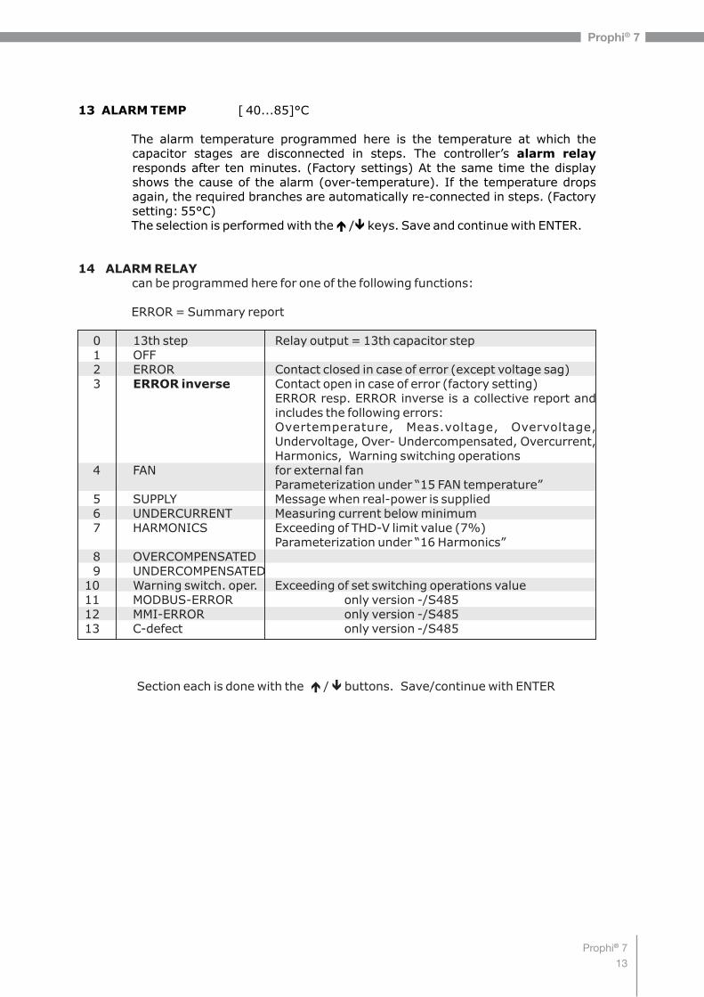
13 ALARM TEMP [ 40...85]°C
The alarm temperature programmed here is the temperature at which the capacitor stages are disconnected in steps. The controller’s alarm relay responds after ten minutes. (Factory settings) At the same time the display shows the cause of the alarm (over-temperature). If the temperature drops again, the required branches are automatically re-connected in steps. (Factory setting: 55°C)The selection is performed with the é /ê keys. Save and continue with ENTER.
14 ALARM RELAY can be programmed here for one of the following functions:
ERROR = Summary report 0 13th step Relay output = 13th capacitor step 1 OFF 2 ERROR Contact closed in case of error (except voltage sag) 3 ERROR inverse Contact open in case of error (factory setting)
ERROR resp. ERROR inverse is a collective report and includes the following errors:Overtemperature, Meas.voltage, Overvoltage, Undervoltage, Over- Undercompensated, Overcurrent, Harmonics, Warning switching operations
4 FAN for external fanParameterization under “15 FAN temperature”
5 SUPPLY Message when real-power is supplied 6 UNDERCURRENT Measuring current below minimum 7 HARMONICS Exceeding of THD-V limit value (7%)
Parameterization under “16 Harmonics” 8 OVERCOMPENSATED 9 UNDERCOMPENSATED 10 Warning switch. oper. Exceeding of set switching operations value 11 MODBUS-ERROR only version -/S485 12 MMI-ERROR only version -/S485 13 C-defect only version -/S485
Section each is done with the é / ê buttons. Save/continue with ENTER
- 12 -

Prophi® 714
Prophi® 7
15 FAN TEMP * [15...70]°CInput of the switching threshold for the fan. *Only active if option 'Fan' is selected
16 HARMONICS (harmonic limit) [7] % (OFF or 0.5 - 25.5)%A limit for the total harmonic distortion THD-V (in%) can be entered here. When this threshold is exceeded, a message is given. THD-V is the ratio of the geometric sum of the harmonics to the fundamental.
17 HARMONICSselection of harmonics for bar graph-display in Display-Mode[3. 5. 7. - 19.] Odd up to 19th (factory setting)[3. 5. 7. - 33.] Odd up to 33th[2. 3. 4. - 17.] Even and odd up to 17th
18 CONTRASTAdjustment of optimal contrast for the display possible
19 - 28 Programming of all values of the 2nd parameter set*only active if under „INTERFACE: 3 EXT. INPUT“ the function „2nd parameter set“ is activated
From factory side the values of the 2nd parameter are set equal to the ones of the normal parameters. By changing of particular parameters for example the target cos-phi can be changed here. Other cases of application are transformer switch over or change of switching times.By applying a control voltage (110…230V) at the external input the 2nd parameter set is activated with following indicated values:19. I-transformer prim, 20. I-transformer sec., 21. End-stopp, 22. Control series, 23. Control principle, 24. Output 1st step, 25. Target cos-phi, 26. Switch on time, 27. Switch off time, 28. Discharge time.
Marking of the values of the 2nd parameter set and the display of activation appears in the display with this symbol
BASIC SETTINGS: [ NO ] ( YES / NO )When the selection is made with YES and confirmed with ENTER, all parameters are reset to the basic setting made by the PFC-system manufacturer. (Optimal network values when the controller was supplied with a complete PFC-system). If the controller is supplied from the works, this point corresponds to the default setting.
CAUTION: All user settings are lost!
5.3 Programming lock
The Prophi 7-1 is equipped with a programming lock to ensure protection from unauthorized or inadvertent changes to the system parameters. The lock can be activated in Expert Mode1 - item9. If the lock is active, all parameters can be checked but not changed.
- 13 -
2

Prophi® 715
Prophi® 7
Section 6 Manual operation (initial operation, maintenance, service)Programming of fixed stages
In manual operation, capacitor branches can be connected/disconnected in the set control series and switching time - irrespective of prevailing power-line conditions. The starting condition is STOPP (no stages connected). Connections are made by pressing the é key (CAP ON). Pressing ê initially leads back to STOPP mode. Repeated pressing of ê leads to the disconnection of stages (CAP OFF). The active operating status and active power factor are always shown on the display (self-explanatory).
Pressing ENTER takes the user to the menu point "Programming of fixed stages”. Normally, all stages are programmed for automatic operation (default setting).
In special cases, all controller outputs (C1 - C12) may be permanently defined in succession (continued switching via ENTER) for the following statuses:
AUTO: Automatic (normal) operation The relevant output is marked by a capacitor symbol.
FIXED: The output is continuously connected, e.g. for fixed PFC. The output is marked by an underlined capacitor symbol.
OFF: The output is continuously disconnected - e.g. for temporarily disconnecting a defective capacitor. The capacitor symbol for this output is faded out. Minus ( - ) appears.
The active stage is blinking. The required status is set via é /ê. By pressing ENTER, the user saves this step and moves to the next stage.The programmed statuses for the outputs also remain visible on the display in automatic operation.After the required settings have been made, pressing the "Operating Mode” key takes the user to the next menu ("Service”) or further to "Automatic Operation”.
- 14 -
MANUAL MODE------------------
MANUAL MODE------------------
MANUAL MODE------------------
STOP 1.000 CAP ON 0.871 CAP CAP OFF 0.871 CAP
1 2 3 4 5 6 7 8 9 10 11 12 1 2 3 4 5 6 7 8 9 10 11 12 1 2 3 4 5 6 7 8 9 10 11 12
device-Stop connection of steps disconnection of steps
MANUAL MODE------------------
MANUAL MODE------------------
MANUAL MODE------------------
C1 - [AUTO] C1 - [ FIXED] C1 - [OFF]
1 2 3 4 5 6 7 8 9 10 11 12 1 2 3 4 5 6 7 8 9 10 11 12 1 2 3 4 5 6 7 8 9 10 11 12

Prophi® 716
Prophi® 7
- 15 -
Section 7 Service menu
The service menu is reached by the operating-mode key.The stored maximum values of the network parameters can be displayed here as well as the number of switching operations of the individual capacitors and their operating time. The desired stages [in square brackets] can be selected via the arrow keys.* In Version /S485 the max.values are stored including time-stamp!In addition, a fault memory is available, in which the last 40 fault states of the system are stored with fault code and in plain text. (This allows, for example, capturing short lived events of overtemperature or overvoltage)
Action Display
ENTER 1 min/max. VOLTAGE in V ENTER 2 max. REACTIVE POWER in kvar ENTER 3 max. ACTIVE POWER in kW ENTER 4 max. APPARENT POWER in kVA ENTER 5 max. TEMPERATURE in °C / °F ENTER 6 max. THD - V / THD - I in % ENTER 7 RESET the maximum and energy values ENTER 8 SWITCHING OPERATIONS C [1] - ... +/- to C [12] ENTER 9 OPERATING TIME C [1] - ... in h +/- to C [12] ENTER 10 ERROR MEMORY E [1] - .... in plaintext ENTER 11 ERROR MEMORY RESET ENTER 12 TEST RUN ENTER 13 C-POWER (only after a test-run or AUTO-INIT) ENTER Back to 1
TEST-RUNThis menu point allows the user to check the settings of the PFC controller. After activation of the test run, the controller switches each stage ON and OFF successively and calculates the output of the capacitors connected (this procedure is done three times to eliminate possible errors). The values calculated are stored and can be retrieved in the following menu item (C-POWER). At the same time, a plausibility check is conducted with the values programmed.Discrepancies are displayed in plain text afterwards. The following errors can be displayed:
- No measuring voltage present- Measuring voltage too high - check programming- Measuring voltage too low - check programming- No measuring current? - Short circuit link in current transformer?- Phase angle current transformer? k/l or phase transposed ?- Current transformer ratio / 1. step power wrong ?- Control series? - check programming- End stop? - check programming- Capacitor defect or wrong power input
Note: The results displayed are messages intended to help the user trace the cause of the error. Final evaluation remains the responsibility of the user. Under complicated (high load fluctuations) grid conditions, 100% error recognition cannot be guaranteed.

Prophi® 717
Prophi® 7
- 16 -
Section 8.1 Expert mode 1
The expert mode is meant for the adjustment of values which normally should not be changed. As a protection against mal-operation this level has an access code.Factory setting: “6343” The password can be changed in point 22 of expert mode 1.
1 PASSWORD ???? (Factory setting: 6343)
2 BASIC SETTING NEW [NO] (available: NO/YES)Storage of active programming as a new basic setting (usually performed by the PFC-system manufacturer). Caution: The original values are overwritten in the process!
3 SWITCHING OPERATIONS RESET [NO] (available: NO/YES)The stored switching operations of all capacitor stages are reset to zero. Caution: No information is then available about the switching frequency of the stages and thus the status of the network. (Reset of individual stages in Expert-mode 2 )
4 OPERATING TIME RESET [NO] (available: NO/YES)The stored operating times of all outputs are set to zero.(Reset of individual stages in Expert-mode 2 )
5 INTEGRATION TIME [1] s (1...255 sec.)The integration time (the time required to form the mean values of a measurement) can be changed for special applications.
6 SWITCHING POWER max [100] kvar (multiples of the smallest stage)This factor specifies the maximum power which may be switched in one switching step. It can be used to control the intelligent control system, which switches several stages as a function of the power-factor requirement.(Factory setting: 4 times the power of the first stage)
7 SWITCH.TRIGGER IND [66]% (30...100%)Threshold for switching ON of next stage. (a-value)Should not be changed in the normal case!
8 SWITCH.TRIGGER CAP [66]% (30...100%)Threshold for switching OFF next stage. (b-value)It should not be changed in the normal case!
9 OPERATING LOCK [NO] (NO / YES)
10 SWITCHING OPERATIONS WARNING [50,000] (1000 ... 255,000)After an output has performed this number of switching operations, a warning message is displayed. ( Abrasion of capacitor contactors and capacitors)
11 FAST DISCHARGE [NO] (NO or X for the desired stages)If only some stages of a network are equipped with fast discharge equipment, those stages can here be indicated with X. In this case, the desired discharge time for these stages can be specified in the next menu point.
[1] s (1s ..programmed normal discharge time)Only available when fast discharge is programmed. The specified discharge time is then also included in the normal display.
12 DISCHARGE TIME

Prophi® 718
Prophi® 7
13 PHASE I 0° Adjustment of current phase positionSelection of phase of current transformer
14 PHASE V 0° Adjustment of voltage phase position:Between which conductors has the measuring voltage of the controller been connected: L-L resp. L-N of all phases possible.
Phase correction between voltage and current in the measuring system. (refer p.6)
15 C-TEST [YES] ( YES / NO)The power of the particular capacitor stage is calculated during each switching operation and compared with the stage output of the capacitor. If the result varies from the nominal value, an error message is generated. This test can be stopped here.
16 C-FAULT [40] % (10...75 %)The deviation from the rated value of the capacitor, for which a fault message is generated, can be specified here (see point 14)
17 TEST ATTEMPTS [6] ( 2...9)When at least this number of successive measurements has resulted in a fault in the capacitor power, a C-fault message is output.
18 OUTPUT 1. STEP [0...255] (0...2550; 0...25500)The range for entering the stage output can be increased to [0...25500] here (e.g. for high-voltage measurement)
19 CONTROL [3] PHASE ( 3 / 1 )The measuring system of the controller is based on a single phase measurement.3-phase CAP (factory setting): The measurement is converted and all outputs are displayed 3-phase (presuming symmetry in the grid).1-phase CAP: Display and control is only performed for the measured 1-phase value (for example 1-phase compensation in non-symmetric grids)3-phase IND: set-up of an inductive compensation with reactors possible (3- phase)1-phase IND: set-up of an inductive compensation 1-phase3-phase C/I : Mixed compensation possible (CAP/IND)1-phase C/I : (Realization according separate application solution)
20 SUPPLY Setting of the controller in case supply of electric power takes place(1) --- (no reaction) factory setting(2) switch off stepwise(3) total switch off
21 DISPLAY [cos j] (cos j / tan j) Switch over between cosinus or tangens j in the display (all menus)
22 PASSWORD ?The password for ExpertMode can be changed here. All combinations of letters and figures are possible
27 ERROR - DISPLAY BACKLIGHTIf an error or warning message appears in the display -the backlight can change to red light for better attention. Here a modification is possible. (OFF/ white/ red/ pink)

Prophi® 719
Prophi® 7
- 18 -
Section 8.2. Expert mode 2
The additional 2nd expert mode includes all messages for operation, warning and error which are displayed by the Prophi7-1. Here they may be deactivated separately. When deactivated, the indication of the message in the display as well as possible activation of the relay or effects on the control behavior are suppressed.
1 PASSWORD ???? (Factory setting: 6343)Changing of code is possible in ExpertMode1 / item 22
Activation / Deactivation / Setting if delay timeof particular operation, warning and error messages - s. above:
Meas.-voltage; Overvoltage; Overcompensated; Undercompensated; Harmonics!; Overtemperature; Overcurrent; Undervoltage; Switch.Operations!; Undercurrent;
Auto-Init-Error
2 ERROR ME.RELAY [10] min. (1...255min.)Time after which the alarm relay will respond
3 UNDERVOLTAGE [50] % (20 ...100 %)meas. voltage below this threshold will switch OFF allstages at the same time
4 OVERVOLTAGE [130] % (105 ...140 %)meas. voltage above this threshold will switch OFF the stages step by step
If the measure voltage returns to the permissible range, the stages will switch ON again.
5 FREQUENCY [40...80 Hz] (50Hz / 60Hz)Measurement by the controller is done automatically in grids of 40 … 80 Hz.In grids with extremely poor voltage quality it is recommend to select a fix frequency (50 or 60 Hz) to avoid measuring errors due to voltage sags.
6 SWITCH. OPERATIONS C 1 RESET [NO] (YES/NO) to C12 RESET [NO] (YES/NO)
Reset of switching operations of particular capacitors possible, e.g. after replacement of particular capacitors or contactors
19 OPERATION TIME C 1 RESET [NO] (YES/NO) to C12 RESET [NO] (YES/NO)
Reset of operation time of particular capacitors possible,
Additionally, switching operations and operation times of the capacitors can be reset.
Modbus-Error; MMI-Error; Remote-disconnect; Remote-stop; Remote-connect; MODBUS-remote; Current<; BusError extern; C-defect; Current>?; Overload equip.; External Error; C-Error Off;

Prophi® 720
Prophi® 7
- 19 -
Section 9 Control principle
The control response of the controller can be selected in programming mode.The controller has four different control modes:
1. Sequential connectionIn sequential connection, the required capacitor stages are successively connected and disconnected in stages (last in - first out). The ranking of each step always corresponds to the power of the smallest stage.Advantage: Exact definition of the next capacitor to be connected in each caseDisadvantage: Long settling time, high switching frequency of the small stages
In order to shorten the settling time, the controller switches several stages simultaneously for a large power-factor requirement. This applies to all control types. The maximum dimensions of the simultaneously switching branches can be changed in expert mode. If the value of the smallest stage is pre-selected, the conventional sequential connection is obtained.
2. Loop connectionIn this variant, the controller operates in loop mode (first in - first out) which minimizes the wear on the capacitor bank, i.e. where stages are of equivalent dimensions, the stage which was disconnected for the longest period of time is always connected next.Advantage: Balanced utilization of equivalent stages and thus an increased operating life of the capacitor bank.Disadvantage: This mode can only be used in control series with groups of the same stage power and long settling time, as every switching step corresponds to the value of the smallest stage.
3. Intelligent loop connection (default setting )The intelligent control principle combines the advantages of the network-sparing loop connection (first in - first out) with a much faster settling time, even for large load skips, and reaches this goal with the fewest possible switching operations of the capacitor stages. The optimized time response is achieved by the simultaneous switching of several or larger capacitor groups as a function of the missing power factor in the power line. Both the number of real switching frequencies of the capacitors as well as the turn-on times of the branches are considered. Advantage: Reaches the target cos phi in a fast-optimized settling time with a low switching frequency of the capacitors.
4. Combined de-tuning (special case for combined de-tuned banks)Within a combined de-tuned application, 2 adjoining equal steps are switched with just one joint choke. This pairwise de-tuning requires an appropriate closed control series (i.e. 1:1:1:1..., 1:1:2:2..., 1:1:2:2:4:4... or similar)The condition for the switching behavior is defined in such a way that the number of activated odd steps is always greater than or equal to the number of activated even steps. The controller complies with the requirements of the control regime while largely conforming to the intelligent switching behavior.
The particular capacitor steps are permanently monitored. In case of a defect capacitor or higher deviation from the nominal output the capacitor will be displayed inverted.

Prophi® 721
Prophi® 7
- 20 -
Section 10 Display-Editor
The Display-editor is reached by activation the operation button. In the Display-editor a selection of measuring values can be performed which shall be displayed in the Display-mode.Out of the available measuring values shown below 3 values can be selected sequently which then are available in the Display-mode as large letters. Selection is done by the arrow-buttons, confirmation with ENTER:
1 Grid voltage 2 Apparent current 3 Reactive power4 Active power5 Apparent power6 Difference reactive power7 Frequency8 Temperature9 THD-V10 THD-I11 Cos Phi12 Tan Phi13 --- (no display)
Example: Display in DISPLAY-MODE
Selected parameters:1. Grid voltage2. Apparent current3. Reactive power
Note:Even in Display-Mode the device will continue to operate as P.F.controller in the background with all functions programmed!
Section 11 Initial operation
The controller must have been installed before being set up and operated.All network-specific parameters are fully programmed as described in section 5 (Programming) by being entered in sequence and stored. The controller is then set to automatic operation with the operating mode key. It is now ready for operation.
Section 12 Maintenance and warranty
The Prophi7-1 should need no maintenance if the operating conditions are observed. However, it is recommended that a functional check of the controller be performed in conjunction with the regular checking of the capacitor bank. In the event of any interventions in the controller during the warranty period, all warranty claims lapse.
DISPLAY-EDITOR------------------
1.DISPLAY [ 1]
[ LINE VOLTAGE ]
------------------
------------------
U
I
Q
223.0 V
268 A
107 kvar

Prophi® 722
Prophi® 7
Section 13: Menu INTERFACE
The controller is optionally equipped with a RS485-interface, an internal clock, a potential free external input (110 … 230 V) and an additional message relay. Therefore the following functions are only available for version /S485:
1 MESSAGE RELAY [1]Functions and settings see section 2.3 Error messages (p.7)
2 FAN TEMPERATURE Input of switching threshold, when message relay = FAN has been selected.
3 EXTERNAL INPUT The function of the external input (110..230 V) can be selected here: (Not active if message relay is programmed as “External” or „Remote control“.
[0] - OFF[1] - 2nd parameter set
Activation of the input in this operation mode releases the 2nd parameter set featuring the following settings: 19/20 I-transformer; 21 End stop; 22 Control series; 23 Control principle; 24 Output 1st step; 25 Target cos-phi; 26-28 Switching times
[2] - EXTERNAL ERROR In this operation mode the activation of the input causes a controlled switch off of all steps (remote switch off)
[3] - Q-OFFSET By activating of the input in this operation mode an additional capacitive output is switched on independent from target cos-phi and controlling (value in offset-power programmable).
[4] - Coupling operation parallel – Coupling operation of two systems, the input receives a signal of the coupling switch between the systems, the systems symmetrically (parallel) switch on the steps.
[5] - Coupling operation serial – Coupling operation of two systems, the input receives the signal of the coupling switch between the systems, the systems sequentially switch in the steps (first system 1, then system 2)
[6] [INPUT FIXED STEP]
4 OFFSET POWER (Fixed power step) – only if external input on Q-OFFSET!Input of reactive power value that is added when activating the input to the required reactive power.
5 ... 9 Adjusting of internal CLOCK (HOUR, MINUTE, DATE)
10 PROTOCOL-----MODBUS KTRMODBUS RTU Modbus-protocol for individual usageASCII OUT Transmitting of grid-values as ASCII-Data,
permanent sequential output of:U, I, Q, P, S, switched steps (display ”XXX---------” = 3 active steps)
MASTER MMI Adjustment in case of real current measurement with MMI6000/7000 (s. application p. 29)
EXTERNAL Usage of an external measuring device (MMI6000/MMI7000). The values of this device are used for display and controlling.
SLAVE HYBRID Operation mode as slave in hybrid-systems (s. page 28)SLAVE MODE Coupling of several controllers via interface (s. page 28)MASTER MODE see above

Prophi® 723
Prophi® 7
Depending on the selected protocol the following settings may be partially deactivated:
11 BAUDRATE Baudrate 9600...256000 adjustableParity NONE, ODD, EVEN selectable
12 ADRESS [1] (1...255)
13 Number MMI [1] (1...9) Number of connected MMI
14 Type of measuring device (MMI6000 / MMI7000 / UCM-5)
15 Number of Prophi7-1 (1...4) Connected devices during cascading
16 ASCII transmit. interval [10] sec. (1-255) Repeat. time ASCII transmission
17 Separator (for ASCII Protocol)Selection HT; LF/CR; SP; CR/LF; Minus; CSV
Following functions can be realized via the interface:
R Parameterization of the controller via PCR Remote read out of the grid parameters, storage and display via PC-software
BR7000-SOFT during online operationR Usage as system interfaceR Selection MODBUS or ASCII (see above)R Usage with accessory MMI6000/MMI7000 for real current or remote measuringR Connection of system accessory (e.g. datalogger)
Instructions for bus wiring when using the interface
R For bus wiring screened cable has to be used!R The bus wirings (incoming and outgoing leads) always have to be applied directly to
the device (no branch boxes)!R In the devices at the end of the busses the terminating resistors integrated in the
device have to be activated (DIP-switch ON).
Connecting plan INTERFACE:
- 22 -
1 2
EXT. IN-/ OUTPUTINTERFACE RS 485On
SERVICE
Gnd B A PE
ext. input110...230V
message-relay
Switch forterminating resistor
Vb Vm Im
L N L1 N k l (L3) (L2)

Prophi® 724
Prophi® 7
- 23 -
Fault
At target cos phi=1 and inductive load, switch-off or connection of capacitor in the corrected line Supply / Drawing mismatched Wrong line cos phi is displayed
Display:"UNDER CURRENT”
Display: "OVERCURRENT”Alarm relay: after 10 min.
Display: "UNDERCOMPENSATED”Alarm relay: after 10 min.
Display: "OVERCOMPENSATED”Alarm relay: after 10 min.
Display: "MEASUREMENT VOLTAGE ???”Alarm relay: after 10 min.
Display: "OVERTEMPERATURE”Alarm relay: after 10 min.
Stages are disconnected for an inductive line or connected for a capacitive line
The controller does not connect all stages, or cos phi does not change at the last stagesIn automatic operation, individual stages are not connected or disconnected
In strongly asymmetrically loaded lines, differences may occur between control r e s p o n s e a n d p o w e r - f a c t o r measurement, as the power factor is measured in single phase.
No operating voltage
Check / Solution
Check terminals of the measuring voltage and current (l and k)!Check phase position
See above
Current in measuring range?Line interruption?Wrong current-converter factor?Current transformer short-circuited?
Check current-converter ratioGo through measuring current range
Check connection and phase position!All stages connected - target cos phi not reached: compensation network sufficiently dimensioned?
Check connection and phase position!Capacitive grid, although all stages disconnectedNo measurement voltage!
Cabinet temperature too high: Outputs are switched off in stages irrespective of power-line conditionsIf a target cos phi is set which deviates from 1 despite an inductive line load, the display < (disconnect stages) may light up. The arrows indicate the control direction and not the line conditions.
Check END STOPP !
Check whether individual stages are programmed as fixed stages or OFF in the "Manual operation / Fixed stages” menu!
Line measurements allow the most favorable phase for measuring the power factor to be determined. The current converter is set accordingly for the measuring current.
Note: No display
Annex 1: Troubleshooting

Prophi® 725
Prophi® 7
- 24 -
Annex 2: Technical data
Type seriesOutputsLanguagesSwitching power of relay outputsNumber of active outputsOperation and display
Number of control seriesUser-defined control series Control principle
Auto-InitOperating voltageMeasuring voltageMeasuring currentPower drawnSensitivityTarget cos phi
Connecting timeDisconnecting timeDischarge time
Fixed stages/ skipped stagesAlarm relayNo-voltage triggering
Display of power-line parameters
Storage of maximum values
Storage of switching number Storage of operating time
Temperature measurement rangeError memoryAccuracy
Housing
WeightOperating ambient temperature
Protection type to DIN 40 050Safety guidelinesSensitivity to interference(industrial areas)
Prophi7-112 (13)D / E / ES / RU / NL / CZ / PL / F / PT / TR250 VAC, 1000 WProgrammableIlluminated graphic display, 128x64dot
201Sequential connection, loop connection orself-optimized switching responseFour-quadrant operationYES110...230 VAC +/-15%, 50 / 60Hz 30...440V~ (L-N) resp. 50...760V~ (L-L)X : 5 / 1A selectable< 5 VA20 mA0.1 inductive to 0.1 capacitive adjustable
Selectable from 1 sec ... 20 min.Selectable from 1 sec ... 20 min.Selectable from 1 sec ... 20 min.
ProgrammableStandardStandard
Power factor, voltage, apparent current, frequency, reactive-, active-, apparent power, missing kvar, temperature, harmonics
Voltage, reactive power, active power, apparent power, temperature, THD-V, THD-I Yes, each output, individual reset possibleYes, each capacitor, individual reset possible
-30°C ... 100°CLast 40 error states are storedCurrent, voltage: 1%Reactive-, active-, apparent power: 2%Switchboard-integrated housingDIN 43 700, 144 x 144 x 53 mm1 kg-20 to +60°C
Front: IP 54, Rear: IP 20IEC 61010-1:2001, EN 61010-1:2001EN 50082-1:1995IEC 61000-4-2: 8kVIEC 61000-4-4: 4kV

Prophi® 726
Prophi® 7
- 25 -
Annex 3: Table of control series
No.
1234567891011121314151617181920
"E"
Control series
1 : 1 : 1 : 1 : 1 : 1 : 1 : 1 : 1 : 1 : 1 : 11 : 2 : 2 : 2 : 2 : 2 : 2 : 2 : 2 : 2 : 2 : 21 : 2 : 3 : 3 : 3 : 3 : 3 : 3 : 3 : 3 : 3 : 31 : 2 : 3 : 4 : 4 : 4 : 4 : 4 : 4 : 4 : 4 : 41 : 2 : 4 : 4 : 4 : 4 : 4 : 4 : 4 : 4 : 4 : 41 : 2 : 3 : 6 : 6 : 6 : 6 : 6 : 6 : 6 : 6 : 61 : 2 : 4 : 8 : 8 : 8 : 8 : 8 : 8 : 8 : 8 : 81 : 1 : 1 : 1 : 2 : 2 : 2 : 2 : 2 : 2 : 2 : 21 : 1 : 1 : 1 : 1 : 6 : 6 : 6 : 6 : 6 : 6 : 61 : 1 : 2 : 2 : 2 : 2 : 2 : 2 : 2 : 2 : 2 : 21 : 1 : 2 : 2 : 2 : 4 : 4 : 4 : 4 : 4 : 4 : 41 : 1 : 2 : 2 : 4 : 4 : 4 : 4 : 4 : 4 : 4 : 41 : 1 : 1 : 2 : 2 : 2 : 2 : 2 : 2 : 2 : 2 : 21 : 1 : 2 : 3 : 3 : 3 : 3 : 3 : 3 : 3 : 3 : 31 : 1 : 2 : 4 : 4 : 4 : 4 : 4 : 4 : 4 : 4 : 41 : 1 : 2 : 4 : 8 : 8 : 8 : 8 : 8 : 8 : 8 : 81 : 2 : 2 : 3 : 3 : 3 : 3 : 3 : 3 : 3 : 3 : 31 : 2 : 3 : 4 : 4 : 8 : 8 : 8 : 8 : 8 : 8 : 81 : 2 : 2 : 4 : 4 : 4 : 4 : 4 : 4 : 4 : 4 : 41 : 2 : 2 : 2 : 4 : 4 : 4 : 4 : 4 : 4 : 4 : 4
Control-series editor
Loop connection
PossiblePossiblePossiblePossiblePossiblePossiblePossiblePossiblePossiblePossiblePossiblePossiblePossiblePossiblePossiblePossiblePossiblePossiblePossiblePossible
Possible
Control -series editor (programming up to a rating of 30)
The control-series editor allows the user to simply define his/her own control series if the required control series is not available for any reason.The last control series - Control Series E - is selected by pressing the "Programming” key (point 4: Control series) and confirmed with ENTER. This leads to the insertion of an additional menu point in the main menu -> the control-series editor. It may be reached via the "Operating Mode” key.
In the control-series editor, all stages can be set in succession to the desired value with the selection keys é / ê. The next stage in each case is reached by pressing ENTER. In the control series editor, the various steps may be programmed up to a rating of 30 (!). The rating >9 is indicated in the display as follows:10=A, 11=B, 12=C, 13=D, 14=E, 15=F, 16=G .... 30=U
The maximum number of stages can be limited by a programmed END STOPP < 12.
ALL control series can be generated (even downwards). The customer will decide whether the generated control series is of sense.
ProgrammingAutomatic Control serieseditor
Manual operation Service
Prophi® 727
Prophi® 7
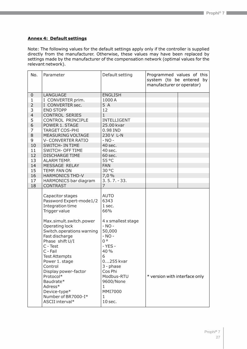
Annex 4: Default settings
No.
0123456789101112131415161718
Parameter
LANGUAGEI CONVERTER prim.I CONVERTER sec.END STOPPCONTROL SERIESCONTROL PRINCIPLEPOWER 1. STAGETARGET COS-PHIMEASURING VOLTAGEV- CONVERTER RATIOSWITCH- IN TIMESWITCH- OFF TIMEDISCHARGE TIMEALARM TEMP. MESSAGE RELAY TEMP. FAN ONHARMONICS THD-VHARMONICS bar diagramCONTRAST
Capacitor stagesPassword Expert-mode1/2Integration timeTrigger value
Max.simult.switch.powerOperating lockSwitch.operations warningFast dischargePhase shift U/IC - TestC - FailTest AttemptsPower 1. stageControlDisplay power-factorProtocol*Baudrate*Adress*Device-type*Number of BR7000-I*ASCII interval*
Default setting
ENGLISH1000 A5 A121INTELLIGENT25.00 kvar0.98 IND230 V L-N- NO -40 sec.40 sec.60 sec.55 °CFAN30 °C7,0 %3. 5. 7. - 33.7
AUTO63431 sec.66%
4 x smallest stage - NO -50,000- NO -0 °- YES -40 %60...255 kvar3 - phaseCos PhiModbus-RTU9600/None1MMI7000110 sec.
Programmed values of this system (to be entered by manufacturer or operator)
* version with interface only
Note: The following values for the default settings apply only if the controller is supplied directly from the manufacturer. Otherwise, these values may have been replaced by settings made by the manufacturer of the compensation network (optimal values for the relevant network).
- 26 -

Prophi® 728
Prophi® 7
Application:Coupling of two PFC-systems using 2 controllers Prophi7-1/S485
The coupling of two compensation systems via the interface of PF-controllers Prophi7-1 offers following advantages:- no sum current transformer and no current transformer switching required- easy installation, real dynamic compensation of both compensation systems
Programming:1. “Master”: Menu INTERFACE / 3 EXTERNAL INPUT: COUPLING PAR. (systems will switching symmetrically) OR
COUPLING SER. (systems will switching one after another) 10 PROTOCOL: COUPLING MODE 11 BAUDRATE: free (the same at each device)
2. Controller of 2nd system: Menu INTERFACE/ 10 PROTOCOL: MODBUS RTU; 11 BAUDRATE: equal to Master-controller; 12 ADRESS: 1
No additional settings are required.
Application example:Two separate systems operate at two transformers; a coupling via a coupling switch exists between both systems
1) Coupling is open: Both systems work completely independent.
2) Coupling is closed: Due to controller coupling, the two PFC systems are operated in PARALLEL (symmetrically) or in SERIES (as extension).Undesired interactions of the compensation system are avoided during operation at a common bus bar (oscillation).
Description:During controller coupling each controller measures its respective current. The measuring values of reactive power difference are transmitted via interface to the „Master“. The “Master” controls and synchronizes the switching of both controllers. No additional installation required.
Installation:The coupling of the 2 PF-controllers Prophi7-1/S485 is done via interface (RJ45 plug) using a standard LAN-cable CAT5 . The 110…230~ signal “Coupling switch closed” has to be conducted to the potential free external input of a controller ( “Master”).
Interface(RJ45)
ext. input (110...230V~)
LAN-cable (CAT5/CAT6)
Interface(RJ45)
Ct1X / 5A
Ct2X / 5A
Transformer 1 Transformer 2
Coupler
Consumer (1)
Prophi7-1/S485(Master)
Prophi7-1/S485(Slave)
Consumer (2)
Capacitor system 1 Capacitor system 2
Feed 1 Feed 2
- 27 -

Prophi® 729
Prophi® 7
Application: Mixed dynamical compensation system and cascading controllers
Variant 1:Hybrid-system with one dynamical and 1...2 standard PF-controllers up to 36 outputs
Prophi 7-1/ Prophi 7-1/S485 Prophi 7-1/S485
Variant 2:Extended systems with up to 48 outputs by cascading of 2...4 pcs. Prophi 7-1/S485(all controllers will switch symmetrically)
Programming in menu “INTERFACE”
10 PROTOCOL: [Master Mode] [Slave Mode] [Slave Mode] 11 BAUDRATE: [38400/NONE] [38400/NONE] [38400/NONE] 12 ADRESS: [1] [2] 15 NUMBER: [2] (1...4)
Prophi7-1/S485 Prophi7-1/S485 Prophi7-1/S485
A mixed dynamical compensation system implements economically the advantages of a dynamic fast network. (Fast changing loads are compensated dynamically and basic loads / slowly changing loads are compensated conventionally)For designing a mixed-dynamical compensation system a special controller is available:The Prophi7-1-TH supports up to 12 transistor-outputs (for triggering thyristor modules) and additional 12 relay-outputs for standard capacitor contactors. It supports also triggering of up to 32 thyristor-switches TSM-LC-S in a network for bigger dynamical systems.Please compare the separate manual.
In case more than 12 standard-stages are required, the following applications are supported.
TH
- 28 -
Prophi7-1-TH up to 2 Prophi 7-1/S485 (for dynamical steps) (for conventional steps)
Menu: PROGRAMMING Menu: INTERFACE
2 CONTROL-MODE: 7...14 Protocol: [Slave Hybrid]Baudrate: [38400/NONE]
Adress:[1] Adress:[2]
LAN-Cable (CAT5/CAT6) LAN-Cable (CAT5/CAT6)
AdapterCV-1xRJ45-BR6000
LAN-Cable (CAT5/CAT6) LAN-Cable (CAT5/CAT6)
AdapterCV-1xRJ45-BR6000

Prophi® 730
Prophi® 7
- 29 -
Application
For permanent current monitoring inside the compensation system the MMI6000 is recommended as an accessory. This measuring device is able to determine the sum current of the complete PFC system as well as the current of single capacitor branches.By monitoring the current of the installed capacitors, extraordinary grid conditions (e.g. harmonic currents which may cause an overload of capacitors) can be identified. In such a case, the power factor controller switches off the relevant compensation stages as long as the extraordinary situation continues. Monitoring of the capacitor current also means monitoring of the capacitor condition (damages, aging …) and thus gives the opportunity to avoid consequential damages. The MMI6000 will improve the reliability and safety of a PFC-system.
Method of operation:
The MMI6000 measures the sum current inside the PFC system. For this a current transformer has to be installed at the power input of the compensation system. During each switching operation, the actual current change is measured and compared to the rated current of the switched capacitor(s). In between the switching operations the current of the complete system is monitored.
In case the current of a step is too high (default +50%), this step is switched off. The controllers display shows an inverted capacitor symbol. The current is further on checked periodically is the rated current reached again, the step is reactivated.Is the sum current of the complete PFC system too high, stages are switched off one after another and alarm relay is set. Periodical measurements are performed to check whether the current reaches the nominal value again. If so, the step is reactivated.
Settings MMI6000: Settings Prophi7-1:
- Operation mode: Coupling MMI-BR6000 Menu: INTERFACE - Grid: 3-phase - 10 Protocol: MASTER-MMI - 11 Baudrate
- 13 Numbers of MMI Expert-mode 1: - 15 C-Test: YES - 16 C-Error (+/- 50%) (setting of switching threshold)
Principle circuit diagram:
CAUTION:
For the bus-connection a shielded cable has to be used!Bus-connections (in and out) have always to be made directly to the relevant device!The terminating resistors inside the connected devices have to be activated (DIP-switch ON).
Application: Capacitor current monitoring using MMI6000
consumer MMI6000
Interface connection RS485
capacitor system with Prophi7-1/S485
L1
L2
L3
N
Program
Enter
Multi-Measuring
M M I - 6000
Interface

Prophi® 731
Prophi® 7
AUTO MODE------------------
cos 0.987 IND
1 2 3 4 5 6 7 8 9 10 11 12
j
A
A
A
2
2
F
F
U
U
H
H
OC
OC
IND
IND
CAP
CAP
MASTER
MASTER
SLAVE
SLAVE
UC
UC
ME
ME
M
Alarm- and status messages in the display
Message relay was parameterized with a function (only version /S485)
Message occurs in case of error resp.relay is active (s.table)
Status indication (s.table)
Alarm relay has been parameterized with a function
Display of status:
2. parameter set active
Display of present controller status in case a mixed compensation CAP/IND(Switching of capacitive or inductive steps) See ExpertMode 1: 19 CONTROL
In case of controller coupling or extension of systems (several controllers) according to the applications shown in applications page 27/28 the respective message is displayed (Master/Slave) as soon as the connection has successfully been established and the communication works without fault.
Display of alarm and message relay functionsProgramming of alarm relay in: PROGRAMMING: 14 ALARM RELAYProgramming of message relay in: INTERFACE: 1 MESSAGE RELAY
Display of error summary report(relay programmed as ERROR resp. ERROR inverse)
Display FAN-ON (relay programmed : „FAN“)
Display SUPPLY real power (relay programmed: „SUPPLY“)
Display UNDERCURRENT
HARMONICS
OVERCOMPENSATED
UNDERCOMPENSATED
SWITCHING OPERATIONS (number of programmed switch. oper. exceeded)
MODBUS-ERROR or MMI-ERROR
C-DEFECT
13. step (programming only possible for the alarm-relay)
- 30 -

Prophi® 732
Prophi® 7
PROGRAMMING
1 LINE VOLTAGE 230.0 V-L/N
2 APPARENT CURRENT 200.0 A
3 REACTIVE POWER 88.88 kvar
4 ACTIVE POWER 88.88 kW
5 APPARENT POWER 88.88 kVA
6 DIFF. REACT POWER 88.88 kvar
7 FREQUENCY 50.0 Hz
1 I-CT PRIMARY [ 1000 ] A / X A
19 I-CT PRIMARY [ 1000 ] A / X
2 I-CT PRIMARY [ 1000 ] A / X
0 LANGUAGE [ ENGLISH ]
1 CURRENT TRANSF. [ KNOWN ]
AUTO-INIT[ NO ]
2 I-CT SECONDARY
20 I-CT SECONDARY
3 I-CT SECONDARY
8 MEAS. VOLTAGE [ 230 ] V - L/N
9 V - CT RATIO [ NO ]
10 SWITCH-IN TIME [ 40 ] sec.
26 SWITCH-IN TIME [ 40 ] sec.
11 SWITCH-OFF TIME [ 40 ] sec.
27 SWITCH-OFF TIME [ 40 ] sec.
12 DISCHARGE TIME [ 60 ] sec.
28 DISCHARGE TIME [ 60 ] sec.
13 ALARM TEMP. [ 55 °C ]
14 ALARM RELAY [ ERROR inverse]
15 FAN TEMP. [ 30 °C ]
8 TEMPERATURE 25 °C
9 HARMONICS [ 3. ] V: 0.5% - I: 0.1%
10 HARMONICS THD V: 0.5% I: 0.3%
11 SYSTEM-POWER 88.88 kvar
12 ENERGY 88.88 kWh ( + )
13 DATE - TIME06.12.2013 - 15:17:40
18 CONTRAST * * * * * [ 7 ] * * * * *
14 SOFTWAREVERSION
17 HARMONICS [ 3. 5. 7. - 19.]
16 HARMONICS THD-V [ 7 ] %
BASIC SETTINGSRESET - NO -
Changingof valuesby buttons:
After 60 sec. without pressingany button, automatic change
to auto-mode
Settings shown with grey backgroundcolour are active only in case
of certain other settings.If not needed they are not displayed.
BACK
4 CONTROL SERIES [1] [1 1 1 1 1 1 1 1 1 1 1 1]
22 CONTROL SERIES [1] [1 1 1 1 1 1 1 1 1 1 1 1]
5 CONTROL MODE [2] [ INTELLIGENT ]
23 CONTROL MODE [2] [ INTELLIGENT ]
7 TARGET cos Phi [ 0.98 IND ]
25 TARGET cos Phi [ 0.98 IND ]
6 POWER 1. STAGE [ 25 ]. 00 kvar
24 POWER 1.STAGE [ 25 ]. 00 kvar
3 END STOPP [12]
21 END STOPP [12]
4 POWER 1. STAGE [ 25 ].00 kvar
TEST 1...3 (automatic TEST RUN)
AUTO MODE---------------
cosj 1.000 IND
BACK TO 1
1000 A / [5] A
1000 A / [5] A
1000 / [5] A
- 31 -
1 2 3 4 5 6 7 8 9 10 11 12
2
2
2
2
2
2
2
2
2
2
By pressing the cursor buttons (up / down)the stage display mode can be changed

Prophi® 733
Prophi® 7
Operating diagram (Brief programming)Power Factor Controller Prophi 7-1/S485 (V2.0)
MANUAL MODE SERVICE EXPERT.MODE 1
STOPP C 1.00 IND 1 min/max VOLTAGE 0 / 250.0 V
1 PASSWORD ????[ 6343 ]
2 max REACTIVE POWER 88.88 kvar
5 INTEGRATION TIME [ 1 ] s
3 max ACTIVE POWER 88.88 kW
4 max APPARENT POWER 88.88 kVA
5 max TEMPERATURE 40.0 °C
6 max THD V 2.7 % - I 1.0 %
7 MAXIMUM VALUES RESET [ NO ]
10 ERROR MEMORY E [ 1 ] 08H ....
12 TEST RUN [ NO ]
2 BASIC SETTINGS NEW ? [ NO ]
3 SWITCH.OPERATION RESET [ NO ]
4 OPERATING TIME RESET [ NO ]
C1 : AUTO (FIXED / OFF )
C2 : AUTO (FIXED / OFF )
C3 : AUTO (FIXED / OFF )
C4 : AUTO (FIXED / OFF )
C5 : AUTO (FIXED / OFF )
C6 : AUTO (FIXED / OFF )
C7 : AUTO (FIXED / OFF )
C8 : AUTO (FIXED / OFF )
C9 : AUTO (FIXED / OFF )
C10 : AUTO (FIXED / OFF )
C11 : AUTO (FIXED / OFF )
C12 : AUTO (FIXED / OFF )
8 SWITCHING OPER. C [ 1 ] - 123
11 ERROR MEMORY RESET [ NO ]
C - POWERC[1] = 23 kvar MEASC[1] = 25 kvar NOM.
9 OPERATION TIME C [ 1 ] - 12h
6 SWITCH. POWER max [100] kvar
7 SWITCH. TRIGGER IND [ 66 ] %
8 SWITCH. TRIGGER CAP [ 66 ] %
9 PROGRAM LOCK [ NO ]
10 SWITCH. OPERATION WARNING [50 000]
11 FAST DISCHARGE [ NO ]
12 FAST DISCHARGE TIME [ 10 ] s
13 PHASE I 0° [ L1 ] - L1-N
14 PHASE V 0° L1 - [ L1- N ]
15 C - TEST [ YES ]
16 C - FAILURE +/- [ 40 ] %
17 [ 6 ]
TEST ATTEMPT
18 OUTPUT 1.STEP [ 0 ... 255 kvar ]
19 CONTROL [ 3 ] PHASE - CAP
20 SUPPLY [ 1 ] -----
21 DISPLAY [ cos /tan ]
22 CHANGE PASSWORD [ NO]
27 ERROR - BACKLIGHT [ PINK]
Selecting ofcapacitors C1-C12
BACK TO 1
BACK TO 2
BACK TO 1
- 32 -
j j
CONTROL SERIES EDITOR
KVAR-RATIO C1 [ 1 ]1 2 2 2 2 2 2 2 2 2 21
KVAR-RATIO C2 [ 1 ]1 2 2 2 2 2 2 2 2 2 21
KVAR-RATIO C3 [ 2 ]1 2 2 2 2 2 2 2 2 2 21
KVAR-RATIO C4 [ 2 ]1 2 2 2 2 2 2 2 2 2 21
KVAR-RATIO C12 [ 2 ]1 2 2 2 2 2 2 2 2 2 21
BACK TO 1
up to capacitor 12
only available if controlserie “E” is selected

Prophi® 734
Prophi® 7
DISPLAY EDITOR INTERFACE Back toSTART-IMAGE
EXPERT.MODE2
1 PASSWORD ????[ 6343 ]
1. DISPLAY [1] [LINE VOLTAGE]
2. DISPLAY [2] [APPAR. CURRENT]
3. DISPLAY [3] [REACTIVE POWER]
Release [YES] or blocking [NO] ordelay-time of followingreports or alarms:
MEAS. VOLTAGEOVERVOLTAGEOVER-COMPENSATEDUNDERCOMPENSATEDHARMONICS !OVERTEMPERATUREOVERCURRENTUNDERVOLTAGESWITCH. OPERATIONS !MEAS. CURRENT< ??
AUTO-INIT ERROR
MODBUS-ERRORMMI-ERRORREMOTE SWITCH-OFFREMOTE STOPREMOTE SWITCH-INMODBUS-REMOTESYSTEM CURRENT < ?BUS ERROR EXTERNC-DEFECTSYSTEM CURRENT > 0OVERLOAD SYSTEMEXT. ERRORC-DEFECT OFF
4 OVERVOLTAGE [ 130 ] %
5 FREQUENCY [ 50 ] Hz
2 DELAY TIME (ALARM) [ 10 ] min.
3 UNDERVOLTAGE [ 50 ] %.
6 SWITCH. OPERAT. C1 RESET [ NO ]
17 RESET [ NO ]
SWITCH. OPERAT. C12
19 OPERAT. TIME C1 RESET [ NO ]
30 OPERAT. TIME RESET [ NO ]
C12
BACK TO 2
BACK TO 1
C1...C12 (C13)
C1...C12 (C13)
2 FAN TEMPERATURE [ 30°C ]
1 MESSAGE RELAY [1] [ OFF ]
3 EXTERNAL INPUT [0] [ NO ]
9 DATE - YEAR 07 . 12 .[2012]
10 PROTOCOL [ MODBUS RTU ]
11 BAUDRATE [ 9600 / NONE]
12 ADRESS [ 1 ]
13 NUMBER of MMI [ 1 ]
14 DEVICE TYPE [ MMI6000 ]
15 NUMBER of BR7000-1 [ 1 ]
16 ASCII REPEAT INTERVAL [ 10 ] sec.
17 SEPARATOR [ HT - 09H ]
5 TIME - HOUR [10] : 55
6 TIME - MINUTE 10 : [55]
8 DATE - MONAT 07 . [12]. 2012
7 DATE - DAY [07]. 12 . 2012
4 OFFSET POWER [25.00] kvar
- 33 -

Prophi® 735
Prophi® 7