Manual Partes Torre Iluminacion Chicago CPLT_M10.pdf
56
CPLT M10 Engine LDW 1003 Par ts List for Portable Light T owers Engl ish +7(800)700-55-97 +7(861)240-75-77 www.epomarket.ru www.cp.com www.epomarket.ru
-
Upload
romaldoagurto -
Category
Documents
-
view
236 -
download
1
Transcript of Manual Partes Torre Iluminacion Chicago CPLT_M10.pdf

8/11/2019 Manual Partes Torre Iluminacion Chicago CPLT_M10.pdf
http://slidepdf.com/reader/full/manual-partes-torre-iluminacion-chicago-cpltm10pdf 1/56
CPLT M10 Engine LDW 1003
Parts List for Portable Light Towers
English
+7(800)700-55-97
+7(861)240-75-77www.epomarket.ru
www.cp.com www.epomarket.ru

8/11/2019 Manual Partes Torre Iluminacion Chicago CPLT_M10.pdf
http://slidepdf.com/reader/full/manual-partes-torre-iluminacion-chicago-cpltm10pdf 2/56

8/11/2019 Manual Partes Torre Iluminacion Chicago CPLT_M10.pdf
http://slidepdf.com/reader/full/manual-partes-torre-iluminacion-chicago-cpltm10pdf 3/56
Parts Index............................................................................................... 5
Warranty and Liability ............................................................................ 6
Safety Precautions for Portable Light Towers....................................... 7
Ordering Spare Parts ............................................................................ 10
Parts Lists............................................................................................... 11
Printed Matter N°
1310 3012 51
06/2012
Engine LDW 1003CPLT M10
CHICAGO PNEUMATIC- PORTABLE ENERGY DIVISION
www.cp.com

8/11/2019 Manual Partes Torre Iluminacion Chicago CPLT_M10.pdf
http://slidepdf.com/reader/full/manual-partes-torre-iluminacion-chicago-cpltm10pdf 4/56
4
CPLT

8/11/2019 Manual Partes Torre Iluminacion Chicago CPLT_M10.pdf
http://slidepdf.com/reader/full/manual-partes-torre-iluminacion-chicago-cpltm10pdf 5/56
PARTS INDEXCPLT
3-43" TOWER SECTION HDW ASSEMBLY ................................................... 39
4" TOWER SECTION HDW ASSEMBLY ....................................................38
AAXLE ASSEMBLY...................................................................................48, 49
BBALLAST BOX ASSEMBLY........................................................................16
BATTERY ASSEMBLY..................................................................................19
BODY ASSEMBLY ..................................................................................22, 23
BODY,CRADLE HDW ASSEMBLY.......................................................24, 25
BODY DOOR HDW ASSEMBLY ...........................................................26, 27
CCONTROL BOX ASSEMBLY.................................................................30, 31
DDECAL ASSEMBLY................................................................................20, 23
DRAWBAR ASSEMBLY...............................................................................32
EENGINE ASSEMBLY ....................................................................................41
ENGINE, GENSET HDW ASSEMBLY.........................................................42
ENGINE COOLANT ......................................................................................14
ENGINE OIL.............................................................................................12, 13
EXHAUST PIPE ASSEMBLY .......................................................................43
FFLOODLIGHT ASSEMBLY ....................................................................40, 52
FLOODLIGHT HDW ASSEMBLY ...............................................................53
FRAME ASSEMBLY................................................................................44, 45
FRAME,SWIVEL BASE HDW ASSEMBLY..........................................46, 47
FUEL TANK ASSEMBLY........................................................................17, 18
GGANG BOX ASSEMBLY, HDW ASSEMBLY .............................................51
GENCOOL EG................................................................................................14
GENERATOR..................................................................................................54
HHDW DRAWBAR HITCH STANDARD ASSEMBLY........ ........ ........ ........ .35
HDW DRAWBAR STANDARD ASSEMBLY ..............................................34
LLIGHTING ASSEMBLY ................................................................................15
SSERVICE PAK ................................................................................................ 11
TTOWER ASSEMBLY .....................................................................................37
TOWER WINCH ASSEMBLY.......................................................................50
WWINCH DRAWBAR ASSEMBLY.................................................................34
WINCH MANUAL DRAWBAR ASSEMBLY ..............................................33
PART PAGE

8/11/2019 Manual Partes Torre Iluminacion Chicago CPLT_M10.pdf
http://slidepdf.com/reader/full/manual-partes-torre-iluminacion-chicago-cpltm10pdf 6/56
6
INSTRUCTION MANUALINSTRUCTION MANUAL
Warranty and Liability Limitation
Use only authorized parts.
Any damage or malfunction caused by the use of unauthorized parts is not covered
by Warranty or Product Liability.The manufacturer does not accept any liability for any damage arising for modifica-
tions, additions or conversions made without the manufacturer's approval in writing.
Copyright 2012, Chicago Pneumatic Compressors LLC, RockHill SC USA.Any unauthorized use or copying of the contents or any part thereof is prohibited.
This applies in particular to trademarks, model denominations, part numbers and
drawings
Limitation de garantie et de responsabilité
Utiliser uniquement les pièces homologuées.
Tout dommage ou mauvais fonctionnement dû à l’utilisation de pièces non homo-
loguées n’est pas couvert par la garantie ou la responsabilité des produits défectueux.
Le fabriquant décline toute responsabilité en cas de dommage faisant suite à des
modifications, des ajouts ou des conversions effectués sans l’accord écrit du fabri-quant.
Copyright 2012, Chicago Pneumatic Compressors LLC, RockHill SC USA.
Toute utilisation ou copie du contenu, ou d’une parte de celui-ci, non autorisée est
interdite.Cette interdiction s’applique en particulier aux marques de commerce, aux dénomi-
nations des modèles, aux numéros des pièces et aux schémas.
Limitación de garantía y responsabilidadUse sólo piezas autorizadas.
La garantía o responsabilidad del producto no cubre ningún daño o funcionamiento
defectuoso provocado por el uso de piezas no autorizadas.
El fabricante no acepta ninguna responsabilidad por los daños provocados por modi-
ficaciones, adiciones o conversiones realizadas sin la aprobación por escrito del fab-
ricante.
Derechos de reproducción 2012, Chicago Pneumatic Compressors LLC, RockHill
SC USA.
Está prohibida toda utilización o reproducción total o parcial no autorizada de estoscontenidos,
en especial de las marcas registradas, denominaciones de modelos, números de piezas y planos

8/11/2019 Manual Partes Torre Iluminacion Chicago CPLT_M10.pdf
http://slidepdf.com/reader/full/manual-partes-torre-iluminacion-chicago-cpltm10pdf 7/56
1. SAFETY PRECAUTIONS FOR PORTABLE LIGHT TOWERS
To be read attentively and acted accordingly before towing, lifting, operating, performing maintenance or repairing the Light Towers
1.1 INTRODUCTION
The policy of Chicago Pneumatic is to provide the users of their equipmentwith safe, reliable and efficient products. Factors taken into account are amongothers:- the intended and predictable future use of the products, and the
environments in which they are expected to operate,- applicable rules, codes and regulations,- the expected useful product life, assuming proper service and
maintenance,- providing the manual with up-to-date information.
Before handling any product, take time to read the relevant instruction manual.Besides giving detailed operating instructions, it also gives specificinformation about safety, preventive maintenance, etc.Keep the manual always at the unit location, easy accessible to the operating
personnel.
See also the safety precautions of the engine and possible other equipment,which are separately sent along or are mentioned on the equipment or parts of the unit.
These safety precautions are general and some statements will therefore notalways apply to a particular unit.
Only people that have the right skills should be allowed to operate, adjust, perform maintenance or repair on Chicago Pneumatic equipment. It is theresponsibility of management to appoint operators with the appropriatetraining and skill for each category of job.
Skill level 1: Operator
An operator is trained in all aspects of operating the unit with the push-buttons,and is trained to know the safety aspects.
Skill level 2: Mechanical technician
A mechanical technician is trained to operate the unit the same as the operator.In addition, the mechanical technician is also trained to perform maintenanceand repair, as described in the instruction manual, and is allowed to changesettings of the control and safety system. A mechanical technician does notwork on live electrical components.
Skill level 3: Electrical technician
An electrical technician is trained and has the same qualifications as both theoperator and the mechanical technician. In addition, the electrical technician
may carry out electrical repairs within the various enclosures of the unit. Thisincludes work on live electrical components.
Skill level 4: Specialist from the manufacturer
This is a skilled specialist sent by the manufacturer or its agent to performcomplex repairs or modifications to the equipment.
In general it is recommended that not more than two people operate the unit,more operators could lead to unsafe operating conditions. Take necessary stepsto keep unauthorized persons away from the unit and eliminate all possiblesources of danger at the unit.
When handling, operating, overhauling and/or performing maintenance or repair on Chicago Pneumatic equipment, the mechanics are expected to usesafe engineering practices and to observe all relevant local safety requirementsand ordinances. The following list is a reminder of special safety directives and
precautions mainly applicable to Chicago Pneumatic equipment.
These safety precautions apply to machinery processing or consuming air.Processing of any other gas requires additional safety precautions typical to theapplication and are not included herein.
Neglecting the safety precautions may endanger people as well as environmentand machinery:- endanger people due to electrical, mechanical or chemical influences,- endanger the environment due to leakage of oil, solvents or other
substances,- endanger the machinery due to function failures.
All responsibility for any damage or injury resulting from neglecting these
precautions or by non-observance of ordinary caution and due care requiredhandling, operating, maintenance or repair, also if not expressly mentionedthis instruction manual, is disclaimed by Chicago Pneumatic.
The manufacturer does not accept any liability for any damage arising from tuse of non-original parts and for modifications, additions or conversions mawithout the manufacturer’s approval in writing.
If any statement in this manual does not comply with local legislation,
stricter of the two shall be applied.
Statements in these safety precautions should not be interpreted as suggestiorecommendations or inducements that it should be used in violation of aapplicable laws or regulations.
1.2 GENERAL SAFETY PRECAUTIONS
1 The owner is responsible for maintaining the unit in a safe operatcondition. Unit parts and accessories must be replaced if missing unsuitable for safe operation.
2 The supervisor, or the responsible person, shall at all times make sure tall instructions regarding machinery and equipment operation amaintenance are strictly followed and that the machines with accessories and safety devices, as well as the consuming devices, are good repair, free of abnormal wear or abuse, and are not tampered with.
3 Whenever there is an indication or any suspicion that an internal part omachine is overheated, the machine shall be stopped but no inspecticovers shall be opened before sufficient cooling time has elapsed; thisavoid the risk of spontaneous ignition of oil vapour when air is admitted
4 Normal ratings (pressures, temperatures, speeds, etc.) shall be duramarked.
5 Operate the unit only for the intended purpose and within its rated lim(pressure, temperature, speeds, etc.).
6 The machinery and equipment shall be kept clean, i.e. as free as possifrom oil, dust or other deposits.
7 To prevent an increase in working temperature, inspect and clean htransfer surfaces (cooler fins, intercoolers, water jackets, etc.) regularSee the maintenance schedule.
8 All regulating and safety devices shall be maintained with due careensure that they function properly. They may not be put out of action.
9 Care shall be taken to avoid damage to safety valves and other pressurelief devices, especially to avoid plugging by paint, oil coke or daccumulation, which could interfere with the functioning of the device.
10 Pressure and temperature gauges shall be checked regularly with regardtheir accuracy. They shall be replaced whenever outside acceptabtolerances.
11 Safety devices shall be tested as described in the maintenance schedulethe instruction manual to determine that they are in good operaticondition.
12 Mind the markings and information labels on the unit.
13 In the event the safety labels are damaged or destroyed, they must replaced to ensure operator safety.
14 Keep the work area neet. Lack of order will increase the risk of acciden
15 When working on the unit, wear safety clothing. Depending on the kind
activities these are: safety glasses, ear protection, safety helmet (includivisor), safety gloves, protective clothing, safety shoes. Do not wear hair long and loose (protect long hair with a hairnet), or wear looclothing or jewelry.
16 Take precautions against fire. Handle fuel, oil and anti-freeze with c because they are inflammable substances. Do not smoke or approach wnaked flame when handling such substances. Keep a fire-extinguisherthe vicinity.
8/11/2019 Manual Partes Torre Iluminacion Chicago CPLT_M10.pdf
http://slidepdf.com/reader/full/manual-partes-torre-iluminacion-chicago-cpltm10pdf 8/56
8
1.3 SAFETY DURING TRANSPORT AND INSTALLATION
To lift a unit, all loose or pivoting parts, e.g. doors and towbar, shall first besecurely fastened.
Do not attach cables, chains or ropes directly to the lifting eye; apply a cranehook or lifting shackle meeting local safety regulations. Never allow sharp
bends in lifting cables, chains or ropes.
Helicopter lifting is not allowed.It is strictly forbidden to dwell or stay in the risk zone under a lifted load.
Never lift the unit over people or residential areas. Lifting acceleration and
retardation shall be kept within safe limits.1 Before towing the unit:
- check the towbar, the brake system and the towing eye. Also check thecoupling of the towing vehicle,
- check the towing and brake capability of the towing vehicle,- check that the towbar, jockey wheel or stand leg is safely locked in the
raised position,- ascertain that the towing eye can swivel freely on the hook,- check that the wheels are secure and that the tyres are in good condition
and inflated correctly,- connect the signalisation cable, check all lights and connect the
pneumatic brake couplers,- attach the safety break-away cable or safety chain to the towing vehicle,- remove wheel chocks, if applied, and disengage the parking brake.
2 To tow a unit use a towing vehicle of ample capacity. Refer to thedocumentation of the towing vehicle.
3 If the unit is to be backed up by the towing vehicle, disengage the overrun brake mechanism (if it is not an automatic mechanism).
4 Never exceed the maximum towing speed of the unit (mind the localregulations).
5 Place the unit on level ground and apply the parking brake beforedisconnecting the unit from the towing vehicle. Unclip the safety break-away cable or safety chain. If the unit has no parking brake or jockeywheel, immobilize the unit by placing chocks in front of and/or behind thewheels. When the towbar can be positioned vertically, the locking devicemust be applied and kept in good order.
6 To lift heavy parts, a hoist of ample capacity, tested and approvedaccording to local safety regulations, shall be used.
7 Lifting hooks, eyes, shackles, etc., shall never be bent and shall only havestress in line with their design load axis. The capacity of a lifting devicediminishes when the lifting force is applied at an angle to its load axis.
8 For maximum safety and efficiency of the lifting apparatus all lifting
members shall be applied as near to perpendicular as possible. If required,a lifting beam shall be applied between hoist and load.
9 Never leave a load hanging on a hoist.
10 A hoist has to be installed in such a way that the object will be lifted perpendicular. If that is not possible, the necessary precautions must betaken to prevent load-swinging, e.g. by using two hoists, each atapproximately the same angle not exceeding 30° from the vertical.
11 Locate the unit away from walls. Take all precautions to ensure that hot air exhausted from the engine and driven machine cooling systems cannot berecirculated. If such hot air is taken in by the engine or driven machinecooling fan, this may cause overheating of the unit; if taken in for combustion, the engine power will be reduced.
1.4 SAFETY DURING USE AND OPERATION
1 When the unit has to operate in a fire-hazardous environment, each engineexhaust has to be provided with a spark arrestor to trap incendiary sparks.
2 The exhaust contains carbon monoxide which is a lethal gas. When theunit is used in a confined space, conduct the engine exhaust to the outsideatmosphere by a pipe of sufficient diameter; do this in such a way that noextra back pressure is created for the engine. If necessary, install anextractor. Observe any existing local regulations. Make sure that the unit
has sufficient air intake for operation. If necessary, install extra air intakeducts.
3 When operating in a dust-laden atmosphere, place the unit so that dust isnot carried towards it by the wind. Operation in clean surroundingsconsiderably extends the intervals for cleaning the air intake filters and thecores of the coolers.
4 Never remove a filler cap of the cooling water system of a hot engine. Waituntil the engine has sufficiently cooled down.
5 Never refill fuel while the unit is running, unless otherwise stated in theChicago Pneumatic Instruction Book (AIB). Keep fuel away from hot
parts such as air outlet pipes or the engine exhaust. Do not smoke whenfuelling. When fuelling from an automatic pump, an earthing cable should
be connected to the unit to discharge static electricity. Never spill nor leaveoil, fuel, coolant or cleansing agent in or around the unit.
6 All doors shall be shut during operation so as not to disturb the cooling air flow inside the bodywork and/or render the silencing less effective. A door should be kept open for a short period only e.g. for inspection or adjustment.
7 Periodically carry out maintenance works according to the maintenanceschedule.
8 Stationary housing guards are provided on all rotating or reciprocating parts not otherwise protected and which may be hazardous to personnel.Machinery shall never be put into operation, when such guards have beenremoved, before the guards are securely reinstalled.
9 Noise, even at reasonable levels, can cause irritation and disturbancewhich, over a long period of time, may cause severe injuries to the nervous
system of human beings.When the sound pressure level, at any point where personnel normally hasto attend, is:
below 70 dB(A): no action needs to be taken,above 70 dB(A): noise-protective devices should be provided for people
continuously being present in the room, below 85 dB(A): no action needs to be taken for occasional visitors
staying a limited time only,above 85 dB(A): room to be classified as a noise-hazardous area and an
obvious warning shall be placed permanently at eachentrance to alert people entering the room, for evenrelatively short times, about the need to wear ear
protectors,above 95 dB(A): the warning(s) at the entrance(s) shall be completed
with the recommendation that also occasional visitorsshall wear ear protectors,
above 105 dB(A): special ear protectors that are adequate for this noiselevel and the spectral composition of the noise shall be
provided and a special warning to that effect shall be placed at each entrance.
10 Insulation or safety guards of parts the temperature of which can be inexcess of 80 °C (175 °F) and which may be accidentally touched by
personnel shall not be removed before the parts have cooled to roomtemperature.
11 Never operate the unit in surroundings where there is a possibility of taking in flammable or toxic fumes.
12 If the working process produces fumes, dust or vibration hazards, etc., takethe necessary steps to eliminate the risk of personnel injury.
13 When using compressed air or inert gas to clean down equipment, do sowith caution and use the appropriate protection, at least safety glasses, for the operator as well as for any bystander. Do not apply compressed air or inert gas to your skin or direct an air or gas stream at people. Never use itto clean dirt from your clothes.
14 When washing parts in or with a cleaning solvent, provide the requiredventilation and use appropriate protection such as a breathing filter, safetyglasses, rubber apron and gloves, etc.
15 Safety shoes should be compulsory in any workshop and if there is a risk,however small, of falling objects, wearing of a safety helmet should beincluded.
16 If there is a risk of inhaling hazardous gases, fumes or dust, the respiratoryorgans must be protected and depending on the nature of the hazard, somust the eyes and skin.

8/11/2019 Manual Partes Torre Iluminacion Chicago CPLT_M10.pdf
http://slidepdf.com/reader/full/manual-partes-torre-iluminacion-chicago-cpltm10pdf 9/56
17 Remember that where there is visible dust, the finer, invisible particles willalmost certainly be present too; but the fact that no dust can be seen is nota reliable indication that dangerous, invisible dust is not present in the air.
18 Never operate the unit at pressures or speeds below or in excess of itslimits as indicated in the technical specifications.
1.5 SAFETY DURING MAINTENANCE AND REPAIR
Maintenance, overhaul and repair work shall only be carried out by adequatelytrained personnel; if required, under supervision of someone qualified for the job.
1 Use only the correct tools for maintenance and repair work, and only toolswhich are in good condition.
2 Parts shall only be replaced by genuine Chicago Pneumatic replacement parts.
3 All maintenance work, other than routine attention, shall only beundertaken when the unit is stopped. Steps shall be taken to preventinadvertent starting. In addition, a warning sign bearing a legend such as”work in progress; do not start” shall be attached to the starting equipment.On engine-driven units the battery shall be disconnected and removed or the terminals covered by insulating caps.On electrically driven units the main switch shall be locked in open
position and the fuses shall be taken out. A warning sign bearing a legendsuch as ”work in progress; do not supply voltage” shall be attached to thefuse box or main switch.
4 Before dismantling any pressurized component, the Light tower or equipment shall be effectively isolated from all sources of pressure and theentire system shall be relieved of pressure. Do not rely on non-returnvalves (check valves) to isolate pressure systems. In addition, a warningsign bearing a legend such as ”work in progress; do not open” shall beattached to each of the outlet valves.
5 Prior to stripping an engine or other machine or undertaking major overhaul on it, prevent all movable parts from rolling over or moving.
6 Make sure that no tools, loose parts or rags are left in or on the machine. Never leave rags or loose clothing near the engine air intake.
7 Never use flammable solvents for cleaning (fire-risk).
8 Take safety precautions against toxic vapours of cleaning liquids.
9 Never use machine parts as a climbing aid.
10 Observe scrupulous cleanliness during maintenance and repair. Keep away
dirt, cover the parts and exposed openings with a clean cloth, paper or tape.
11 Never weld on or perform any operation involving heat near the fuel or oilsystems. Fuel and oil tanks must be completely purged, e.g. by steam-cleaning, before carrying out such operations. Never weld on, or in anyway modify, pressure vessels. Disconnect the alternator cables during arcwelding on the unit.
12 Support the towbar and the axle(s) securely if working underneath the unitor when removing a wheel. Do not rely on jacks.
13 Do not remove any of, or tamper with, the sound-damping material. Keepthe material free of dirt and liquids such as fuel, oil and cleansing agents.If any sound-damping material is damaged, replace it to prevent the sound
pressure level from increasing.
14 Use only lubricating oils and greases recommended or approved byChicago Pneumatic or the machine manufacturer. Ascertain that theselected lubricants comply with all applicable safety regulations,especially with regard to explosion or fire-risk and the possibility of decomposition or generation of hazardous gases. Never mix synthetic withmineral oil.
15 Protect the engine, alternator, air intake filter, electrical and regulatingcomponents, etc., to prevent moisture ingress, e.g. when steam-cleaning.
16 When performing any operation involving heat, flames or sparks on amachine, the surrounding components shall first be screened with non-flammable material.
17 Never use a light source with open flame for inspecting the interior omachine.
18 When repair has been completed, the machine shall be barred over at leone revolution for reciprocating machines, several revolutions for rotaones to ensure that there is no mechanical interference within the machor driver. Check the direction of rotation of electric motors when startiup the machine initially and after any alteration to the electriconnection(s) or switch gear, to check that the oil pump and the ffunction properly.
19 Maintenance and repair work should be recorded in an operator’s logbofor all machinery. Frequency and nature of repairs can reveal unsa
conditions.
20 When hot parts have to be handled, e.g. shrink fitting, special heresistant gloves shall be used and, if required, other body protection sh
be applied.
21 When using cartridge type breathing filter equipment, ascertain that tcorrect type of cartridge is used and that its useful service life is nsurpassed.
22 Make sure that oil, solvents and other substances likely to pollute environment are properly disposed of.
23 Before clearing the unit for use after maintenance or overhaul, check toperating pressures, temperatures and speeds are correct and that tcontrol and shutdown devices function correctly.
1.6 TOOL APPLICATIONS SAFETY
Apply the proper tool for each job. With the knowledge of correct tool use aknowing the limitations of tools, along with some common sense, maaccidents can be prevented.
Special service tools are available for specific jobs and should be used whrecommended. The use of these tools will save time and prevent damage
parts.
1.7 SPECIFIC SAFETY PRECAUTIONS
Batteries
When servicing batteries, always wear protecting clothing and glasses.
1 The electrolyte in batteries is a sulphuric acid solution which is fatal ihits your eyes, and which can cause burns if it contacts your skTherefore, be careful when handling batteries, e.g. when checking tcharge condition.
2 Install a sign prohibiting fire, open flame and smoking at the post wh batteries are being charged.
3 When batteries are being charged, an explosive gas mixture forms in cells and might escape through the vent holes in the plugs.Thus an explosive atmosphere may form around the battery if ventilatiis poor, and can remain in and around the battery for several hours aftehas been charged. Therefore:- never smoke near batteries being, or having recently been, charged,- never break live circuits at battery terminals, because a spark usua
occurs.
4 When connecting an auxiliary battery (AB) in parallel to the unit batt(CB) with booster cables: connect the + pole of AB to the + pole of C
then connect the - pole of CB to the mass of the unit. Disconnect in treverse order.

8/11/2019 Manual Partes Torre Iluminacion Chicago CPLT_M10.pdf
http://slidepdf.com/reader/full/manual-partes-torre-iluminacion-chicago-cpltm10pdf 10/56
10
ORDERING SPARE PARTS
Always quote the part number, the designation and the quantity of the parts required, as well as the type and the serial number of the machine.
EXPLANATION OF THE COLUMNS
REF : REFERENCE CODE
Establishes the connection between a part in the list and a part in the illus-tration."–" means that the part is not shown in the illustration.
PART NUMBER
If no part number is given, the part cannot be obtained as a spare part.Parts marked with a dot are part of the assembly listed right above them.
DESIGNATION
Usually this is the name of the part. For standard parts, in addition to thename, a number of characteristics are given.
QTY : QUANTITY
Indicates the quantity of the part concerned. "AR" stands for "AsRequired".
COMMANDE DE PIÈCES DETACHEES
Toujours indiquer le numéro de pièce, la désignation, la quantité désiréeainsi que le type et le numéro de série du groupe.
EXPLICATION DES INTITULES DES COLONNES
REF : CODE DE REFERENCE
Réfère à la pièce détachée spécifiée dans la liste et sur l’illustration. "–"implique que la pièce n’est pas indiquée sur l’illustration.
PART NUMBER : NUMERO DE PIECE DETACHEE
Si le numéro n’est pas indiqué, la pièce n’est pas disponible en tant que pièce de rechange.Les pièces indiquées par un point gras font partie de l’ensemble se trou-vant au-dessus des pièces détachées correspondantes.
DESIGNATION
En général, le nom de la pièce. S’il s’agit de pièces standard, outre ladésignation, un certain nombre de caractéristiques sont indiquées.
QTY : QUANTITE
Indique la quantité de la pièce détachée. “AR” indique “As required”,c’est-à-dire la quantité à déterminer selon le cas.
PEDIDO DE PARTES
Siempre comunicar el número de parte, la designación y la cantidaddeseada así como el tipo y el número de serie de la máquina.
INFORMACIONES SOBRE LAS COLUMNAS
REF : CODIGO DE REFERENCIA
Establece la conexión entre una parte en la lista y una parte en la ilus-tración."–" quiere decir que la parte no está ilustrada.
PART NUMBER : NUMERO DE PARTE
Si no se da ningún número, quiere decir que la parte no está disponiblecomo parte de recambio.Partes marcadas con un punto son partes del conjunto indicado más arriba.
DESIGNATION : DESIGNACION
Principalmente el nombre de la parte. En caso de partes estándares, elnombre es seguido por especificaciones.
QTY : CANTIDAD
Indica la cantidad de la parte correspondiente. La indicación "AR" sig-nifica "As Required" (como sea requerido).
ORDERING SPARE PARTS

8/11/2019 Manual Partes Torre Iluminacion Chicago CPLT_M10.pdf
http://slidepdf.com/reader/full/manual-partes-torre-iluminacion-chicago-cpltm10pdf 11/56
1
- 1310 3120 30 SERVICE PAK 250 HRS
•A - OIL FILTER 1
•B - FUEL FILTER 1
- 1310 3120 31 SERVICE PAK 500 HRS / ANNUAL
•A - OIL FILTER 1
•B - FUEL FILTER 1
•C - AIR FILTER 1
REF PART NUMBER DESIGNATION QTY REF PART NUMBER DESIGNATION QT
SERVICE PAK

8/11/2019 Manual Partes Torre Iluminacion Chicago CPLT_M10.pdf
http://slidepdf.com/reader/full/manual-partes-torre-iluminacion-chicago-cpltm10pdf 12/56
12
A 1626 2258 00 GENOIL 5W40 5 LITER CAN 1
B 1626 2259 00 GENOIL 5W40 20 LITER CAN 1
REF PART NUMBER DESIGNATION QTY REF PART NUMBER DESIGNATION QTY
ENGINE OILGENOIL 5W40

8/11/2019 Manual Partes Torre Iluminacion Chicago CPLT_M10.pdf
http://slidepdf.com/reader/full/manual-partes-torre-iluminacion-chicago-cpltm10pdf 13/56
1
A 1626 2262 00 GENOIL 15W40 5 LITER CAN 1
B 1626 2263 00 GENOIL 15W40 20 LITER CAN 1
REF PART NUMBER DESIGNATION QTY REF PART NUMBER DESIGNATION QT
ENGINE OILGENOIL 15W40

8/11/2019 Manual Partes Torre Iluminacion Chicago CPLT_M10.pdf
http://slidepdf.com/reader/full/manual-partes-torre-iluminacion-chicago-cpltm10pdf 14/56
14
A 1626 2255 00 GENCOOL EG 5 LITER CAN 1
B 1626 2256 00 GENCOOL EG 20 LITER CAN 1
C 1626 2257 00 GENCOOL CONCENTRATE 5 LITER CAN 1
REF PART NUMBER DESIGNATION QTY REF PART NUMBER DESIGNATION QTY
ENGINE COOLANTGENCOOL EG

8/11/2019 Manual Partes Torre Iluminacion Chicago CPLT_M10.pdf
http://slidepdf.com/reader/full/manual-partes-torre-iluminacion-chicago-cpltm10pdf 15/56
1
10 1310 0725 23 LICENSE PLATE LIGHT 1
15 1310 0725 49 TAIL LIGHT 2
20 1310 0725 50 TAIL LIGHT GROMMET 2
25 1310 0725 54 BUTT CONNECTOR 1
30 1310 0725 57 RUBBER GROMMET 135 1310 0725 84 REFLECTOR, AMBER 2
40 1310 0725 85 REFLECTOR, RED 2
45 1310 0725 86 REAR TAIL LIGHT HARNESS 1
50 1310 0725 87 MAIN TAIL LIGHT HARNESS 1
REF PART NUMBER DESIGNATION QTY REF PART NUMBER DESIGNATION QT
LIGHTING ASSEMBLY

8/11/2019 Manual Partes Torre Iluminacion Chicago CPLT_M10.pdf
http://slidepdf.com/reader/full/manual-partes-torre-iluminacion-chicago-cpltm10pdf 16/56
16
10 1310 0725 48 SNAP BUSHING 1
15 1310 0725 55 HOLE PLUG 4
20 1310 0726 06 BALLAST 4
25 1310 0727 40 BALLAST BOX 1
30 1310 0728 34 BALLAST BOX TOP 1
REF PART NUMBER DESIGNATION QTY REF PART NUMBER DESIGNATION QTY
BALLAST BOX ASSEMBLY

8/11/2019 Manual Partes Torre Iluminacion Chicago CPLT_M10.pdf
http://slidepdf.com/reader/full/manual-partes-torre-iluminacion-chicago-cpltm10pdf 17/56
1
10 1310 0727 36 FUEL TANK STRAP 2
15 1310 0726 24 FUEL TANK ASSEMBLY 1
(For details see page 18)
REF PART NUMBER DESIGNATION QTY REF PART NUMBER DESIGNATION QT
FUEL TANK ASSEMBLY

8/11/2019 Manual Partes Torre Iluminacion Chicago CPLT_M10.pdf
http://slidepdf.com/reader/full/manual-partes-torre-iluminacion-chicago-cpltm10pdf 18/56
18
- 1310 0726 24 FUEL TANK ASSEMBLY (From page 17)
10 1310 0726 25 FUEL TANK, 30 GALLON 1
15 1310 0726 05 FUEL CAP, 3.5 1
20 1310 0725 81 STAND PIPE 1
25 1310 0727 32 ELBOW FITTING 1
30 1310 0725 52 BRASS PLUG FITTING 1
35 1310 0725 15 BARB FITTING 1
40 1310 0725 14 ELBOW FITTING 1
1310 0726 24_01
REF PART NUMBER DESIGNATION QTY REF PART NUMBER DESIGNATION QTY
FUEL TANK ASSEMBLY

8/11/2019 Manual Partes Torre Iluminacion Chicago CPLT_M10.pdf
http://slidepdf.com/reader/full/manual-partes-torre-iluminacion-chicago-cpltm10pdf 19/56
1
10 1310 0725 13 WASHER 1
15 1310 0725 29 BATTERY CABLE, RED 1
20 1310 0725 31 BATTERY CABLE, BLACK 1
25 1310 0727 22 BATTERY TERMINAL COVER (BLACK) 1
30 1310 0727 23 BATTERY TERMINAL COVER (RED) 135 1310 0727 93 BATTERY BRACKET 1
40 1310 0727 94 BATTERY STAY 1
REF PART NUMBER DESIGNATION QTY REF PART NUMBER DESIGNATION QT
BATTERY ASSEMBLY

8/11/2019 Manual Partes Torre Iluminacion Chicago CPLT_M10.pdf
http://slidepdf.com/reader/full/manual-partes-torre-iluminacion-chicago-cpltm10pdf 20/56
20
DECAL ASSEMBLY

8/11/2019 Manual Partes Torre Iluminacion Chicago CPLT_M10.pdf
http://slidepdf.com/reader/full/manual-partes-torre-iluminacion-chicago-cpltm10pdf 21/56
2
10 1310 0725 08 REFLECTOR-RED,RECT 3
15 1310 0725 66 DECAL-GROUNDING STUD 1
20 1310 0725 67 DECAL-TOWING INSTR.. 1
25 1310 0725 68 DECAL-LIFT HOOK. 230 1310 0725 69 DECAL-DANGER, OVERHEAD. 1
35 1310 0725 70 DECAL-WARNING, STAND CLEAR, WLTC1
40 1310 0725 71 DECAL-WARNING,SECURE M. 1
45 1310 0725 72 DECAL-WARNING,LOWER TO. 1
50 1310 0725 73 DECAL-DANGER,ASPHYXIAT. 1
55 1310 0725 74 DECAL-WARNING,UV RADIAT. 1
60 1310 0725 75 DECAL-DANGER, DIESEL. 1
65 1310 0725 76 DECAL-DANGER,ELEC.STOR. 1
70 1310 0725 77 DECAL-WARNING,AVIOD CRU. 2
75 1310 0725 78 DECAL-WARNING,HOT,HORIZ. 1
80 1310 0726 17 DECAL-OPER.INSTR.RAISE TWR 1
85 1310 0726 18 DECAL-OPER.INSTR.LOWER TWR 1
90 1310 0726 19 DECAL-BEFORE STARTING, 1
95 1310 0726 20 DECAL-DANGER,FALLING MAST 1100 1310 0726 62 DECAL-COOLANT RECOVERY 1
105 1310 0726 66 DECAL-COOLANT RECOVERY 2
110 1310 0726 78 DECAL-NO PRESSURE WASH 1
115 1310 0726 88 DECAL-GROUND SYMBOL 3
120 1310 0726 97 DECAL-LIGHTS,LTC4 TRL. 1
125 1310 0727 35 DECAL-DANGER HIGH VOLTAGE 1
130 1310 0727 45 DECAL,CAUTION 2
135 1310 0727 78 DECAL,TOP CAUTION 1
140 1310 0727 79 DECAL,DOOR LEFT CAUTION 1
145 1310 0727 80 DECAL,DOOR RIGHT CAUTION 1
150 1310 0727 97 DECAL,TIRE PRESSURE 2
155 1310 0728 26 DECALE 2
REF PART NUMBER DESIGNATION QTY REF PART NUMBER DESIGNATION QT
DECAL ASSEMBLY

8/11/2019 Manual Partes Torre Iluminacion Chicago CPLT_M10.pdf
http://slidepdf.com/reader/full/manual-partes-torre-iluminacion-chicago-cpltm10pdf 22/56
22
204406
BODY ASSEMBLY

8/11/2019 Manual Partes Torre Iluminacion Chicago CPLT_M10.pdf
http://slidepdf.com/reader/full/manual-partes-torre-iluminacion-chicago-cpltm10pdf 23/56
2
10 1310 0725 38 WHEEL FENDER 2
15 1310 0725 89 TOWER CRADLE 1
20 - BODY DOOR, HDW ASSY 2
(For details see page 24)25 - BODY SIDE, HDW ASSY 2
30 - BODY CRADLE, HDW ASSY 1
(For details see page 26)
35 - OVERFLOW BOTTLE, HDW ASSY 1
40 - HDW ASSY 1
45 - FRONT BODY, HDW ASSY 1
(For details see page 28)
50 - REAR BODY, HDW ASSY 1
55 1310 0726 81 BUSHING 4
60 1310 0727 86 SIDE PANEL-LEFT HAND 1
65 1310 0728 23 PANEL,BODY,WLTC,DOOR,SQ,REDA 2
70 1310 0728 10 BRACKET OVERFLOW BOTTLE 1
75 1310 0728 19 PANEL,BODY,WLTC,REAR,SQ,REDA 1
80 1310 0727 89 SIDE PANEL-RIGHT HAND 185 1310 0728 25 PANEL,BODY,WLTC,TOP,SQ,RIGID,REDA 1
90 1310 0725 65 BUMPER 1
95 1310 0725 60 BUMPER 3
100 1310 0726 77 LATCH BRACKET 1
110 1310 0726 67 PLUG 1
115 1310 0727 28 TOWER SUPPORT 1
120 1310 0728 21 PANEL,BODY,WLTC,FRONT,SQ,REDA 1
REF PART NUMBER DESIGNATION QTY REF PART NUMBER DESIGNATION QT
BODY ASSEMBLY

8/11/2019 Manual Partes Torre Iluminacion Chicago CPLT_M10.pdf
http://slidepdf.com/reader/full/manual-partes-torre-iluminacion-chicago-cpltm10pdf 24/56
24
201322
BODY DOOR HDW ASSEMBLY

8/11/2019 Manual Partes Torre Iluminacion Chicago CPLT_M10.pdf
http://slidepdf.com/reader/full/manual-partes-torre-iluminacion-chicago-cpltm10pdf 25/56
2
- BODY DOOR HDW (From page 22)
ASSEMBLY
10 1310 0725 64 SLAM LATCH 1
15 1310 0725 80 DOOR HOLDER 1
20 1310 0726 79 BUSHING 2
25 1310 0726 80 SPACER 2
30 1310 0726 82 PIN 2
35 1310 0726 83 SPACER 2
40 1310 0726 87 WIRE ASSY 1
REF PART NUMBER DESIGNATION QTY REF PART NUMBER DESIGNATION QT
BODY DOOR HDW ASSEMBLY
8/11/2019 Manual Partes Torre Iluminacion Chicago CPLT_M10.pdf
http://slidepdf.com/reader/full/manual-partes-torre-iluminacion-chicago-cpltm10pdf 26/56
26
201327
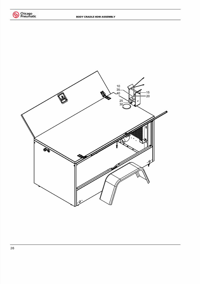
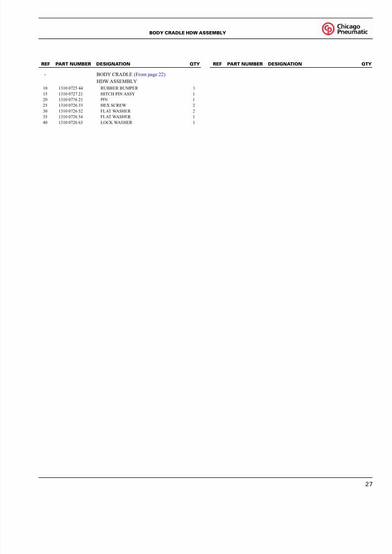
BODY CRADLE HDW ASSEMBLY
8/11/2019 Manual Partes Torre Iluminacion Chicago CPLT_M10.pdf
http://slidepdf.com/reader/full/manual-partes-torre-iluminacion-chicago-cpltm10pdf 27/56
2
- BODY CRADLE (From page 22)
HDW ASSEMBLY
10 1310 0725 44 RUBBER BUMPER 1
15 1310 0727 21 HITCH PIN ASSY 1
20 1310 0726 21 PIN 1
25 1310 0726 33 HEX SCREW 2
30 1310 0726 52 FLAT WASHER 2
35 1310 0726 54 FLAT WASHER 1
40 1310 0726 63 LOCK WASHER 1
REF PART NUMBER DESIGNATION QTY REF PART NUMBER DESIGNATION QT
BODY CRADLE HDW ASSEMBLY

8/11/2019 Manual Partes Torre Iluminacion Chicago CPLT_M10.pdf
http://slidepdf.com/reader/full/manual-partes-torre-iluminacion-chicago-cpltm10pdf 28/56
28
20484
FRONT BODY HDW ASSEMBLY

8/11/2019 Manual Partes Torre Iluminacion Chicago CPLT_M10.pdf
http://slidepdf.com/reader/full/manual-partes-torre-iluminacion-chicago-cpltm10pdf 29/56
2
- FRONT BODY HDW ASSEMBLY (From page 22)
10 1310 0725 04 CORD GRIP 1
15 1310 0726 56 PLASTIC PLUG 1
20 1310 0726 81 BUSHING 4
REF PART NUMBER DESIGNATION QTY REF PART NUMBER DESIGNATION QT
FRONT BODY HDW ASSEMBLY

8/11/2019 Manual Partes Torre Iluminacion Chicago CPLT_M10.pdf
http://slidepdf.com/reader/full/manual-partes-torre-iluminacion-chicago-cpltm10pdf 30/56
30
CONTROL BOX ASSEMBLY

8/11/2019 Manual Partes Torre Iluminacion Chicago CPLT_M10.pdf
http://slidepdf.com/reader/full/manual-partes-torre-iluminacion-chicago-cpltm10pdf 31/56
3
10 1310 0725 34 HOUR METER 1
15 1310 0725 45 CIRCUIT BREAKER 15A 4
20 1310 0725 83 DUPLEX RECEPTACLE 1
25 1310 0725 88 CIRCUIT BREAKER 20A 130 1310 0726 08 CAP 1
35 1310 0726 27 CIRCUIT BREAKER 25A 1
40 1310 0726 85 CAPACITOR 1
45 1310 0728 27 LOAD CENTER BUS 1
50 1310 0728 29 CONTROL BOX PANEL 1
55 1310 0728 30 CONTROL PANEL 1
60 1310 0728 36 BRACKET CAPACITOR 1
65 1310 0728 50 HARNESS ASSEMBLY CONTROL LOM 1
70 - HDW ASSEMBLY CONTROL BOX 1
75 1310 0725 04 CORD GRIP 2
80 1310 0727 04 WEASTP,PSA 1
REF PART NUMBER DESIGNATION QTY REF PART NUMBER DESIGNATION QT
CONTROL BOX ASSEMBLY

8/11/2019 Manual Partes Torre Iluminacion Chicago CPLT_M10.pdf
http://slidepdf.com/reader/full/manual-partes-torre-iluminacion-chicago-cpltm10pdf 32/56
32
10 1310 0725 35 BALL HITCH 1
15 1310 0725 41 SWIVEL JACK, SIDE WIND 1
20 1310 0725 61 SNAP RING 1
25 1310 0725 79 CHAIN ASSEMBLY 2
30 1310 0725 97 DRAWBAR 135 1310 0726 16 BALL HITCH BRACKET 1
40 - WINCH MANUAL DRAWBAR
ASSEMBLY (For details see page 33) 1
45 - WINCH DRAWBAR
ASSEMBLY(For details see page 34) 1
50 - HDW DRAWBAR STANDARD
ASSEMBLY (For details see page 35) 1
55 - HDW DRAWBAR HITCH STANDARD
ASSEMBLY (For details see page 36) 1
204879-C1
REF PART NUMBER DESIGNATION QTY REF PART NUMBER DESIGNATION QTY
DRAWBAR ASSEMBLY

8/11/2019 Manual Partes Torre Iluminacion Chicago CPLT_M10.pdf
http://slidepdf.com/reader/full/manual-partes-torre-iluminacion-chicago-cpltm10pdf 33/56
3
- WINCH MANUAL DRAWBAR (From page 32)
ASSEMBLY
10 1310 0725 07 SINGLE GROOVE PULLEY 1
15 1310 0725 24 CRANK WINCH 1
20 1310 0725 26 HANDLE 1
25 1310 0728 60 CABLE ASSY 1
201391
REF PART NUMBER DESIGNATION QTY REF PART NUMBER DESIGNATION QT
WINCH MANUAL DRAWBAR ASSEMBLY

8/11/2019 Manual Partes Torre Iluminacion Chicago CPLT_M10.pdf
http://slidepdf.com/reader/full/manual-partes-torre-iluminacion-chicago-cpltm10pdf 34/56
34
- WINCH DRAWBAR (From page 32)
ASSEMBLY
10 1310 0726 32 HEX SCREW 3
15 1310 0726 34 HEX SCREW 1
20 1310 0726 47 HEX NUT 4
25 1310 0726 49 PIN 1
30 1310 0726 52 FLAT WASHER 8
35 1310 0726 54 FLAT WASHER 1
201392
REF PART NUMBER DESIGNATION QTY REF PART NUMBER DESIGNATION QTY
WINCH DRAWBAR ASSEMBLY

8/11/2019 Manual Partes Torre Iluminacion Chicago CPLT_M10.pdf
http://slidepdf.com/reader/full/manual-partes-torre-iluminacion-chicago-cpltm10pdf 35/56
3
- HDW DRAWBAR (From page 32)
STANDARD ASSEMBLY
10 1310 0726 37 HEX SCREW 1
15 1310 0726 38 HEX SCREW 2
20 1310 0726 42 HEX NUT 3
25 1310 0726 54 FLAT WASHER 6
203920
REF PART NUMBER DESIGNATION QTY REF PART NUMBER DESIGNATION QT
HDW DRAWBAR STANDARD ASSEMBLY

8/11/2019 Manual Partes Torre Iluminacion Chicago CPLT_M10.pdf
http://slidepdf.com/reader/full/manual-partes-torre-iluminacion-chicago-cpltm10pdf 36/56
36
- HDW DRAWBAR HITCH
STANDARD ASSEMBLY (From page 32)
10 1310 0725 12 HEX SCREW 2
15 1310 0725 19 HEX NUT 2
20 1310 0725 20 LOCK WASHER 2
25 1310 0726 38 HEX SCREW 2
30 1310 0726 42 HEX NUT 2
35 1310 0726 53 FLAT WASHER 4
40 1310 0726 54 FLAT WASHER 4
45 1310 0726 63 LOCK WASHER 2
203922
REF PART NUMBER DESIGNATION QTY REF PART NUMBER DESIGNATION QTY
HDW DRAWBAR HITCH STANDARD ASSEMBLY

8/11/2019 Manual Partes Torre Iluminacion Chicago CPLT_M10.pdf
http://slidepdf.com/reader/full/manual-partes-torre-iluminacion-chicago-cpltm10pdf 37/56
3
10 1310 0725 42 HANDLE 1
15 1310 0725 95 4" TOWER SECTION 1
20 1310 0726 11 3" TOWER SECTION 1
25 1310 0726 15 2" TOWER SECTION 1
30 1310 0727 67 WINCH ASSEMBLY 1(For details see page 50)
35 - 4" TOWER SECTION
HDW ASSEMBLY 1
(For details see page 38)
40 - 3" TOWER SECTION
HDW ASSEMBLY 1
(For details see page 39)
203916-C1
REF PART NUMBER DESIGNATION QTY REF PART NUMBER DESIGNATION QT
TOWER ASSEMBLY

8/11/2019 Manual Partes Torre Iluminacion Chicago CPLT_M10.pdf
http://slidepdf.com/reader/full/manual-partes-torre-iluminacion-chicago-cpltm10pdf 38/56
38
- 4" TOWER SECTION (From page 37)
HDW ASSEMBLY
10 1310 0727 20 HEX SCREW 1
15 1310 0726 44 BLOCK GUIDE 3
20 1310 0727 59 FLAT WASHER 3
25 1310 0726 55 BLOCK GUIDE 2
30 1310 0727 60 HEX NUT 1
201330
REF PART NUMBER DESIGNATION QTY REF PART NUMBER DESIGNATION QTY
4" TOWER SECTION HDW ASSEMBLY
8/11/2019 Manual Partes Torre Iluminacion Chicago CPLT_M10.pdf
http://slidepdf.com/reader/full/manual-partes-torre-iluminacion-chicago-cpltm10pdf 39/56
3
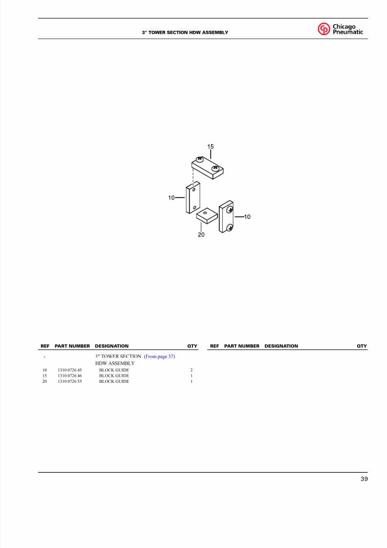
- 3" TOWER SECTION (From page 37)
HDW ASSEMBLY
10 1310 0726 45 BLOCK GUIDE 2
15 1310 0726 46 BLOCK GUIDE 1
20 1310 0726 55 BLOCK GUIDE 1
201331
REF PART NUMBER DESIGNATION QTY REF PART NUMBER DESIGNATION QT
3" TOWER SECTION HDW ASSEMBLY

8/11/2019 Manual Partes Torre Iluminacion Chicago CPLT_M10.pdf
http://slidepdf.com/reader/full/manual-partes-torre-iluminacion-chicago-cpltm10pdf 40/56
40
10 1310 0726 26 T-BAR WELDMENT 2
15 1310 0726 73 COIL CORD 1
20 1310 0727 68 GANG BOX ASSEMBLY 1
(For details see page 51)
25 1310 0727 69 FLOODLIGHT HARDWARE ASSEMBLY 1(For details see page 51)
30 - LIGHT HARDWARE ASSEMBLY 1
(For details see page 53)
35 - T-BAR HARDWARE ASSEMBLY 1
(For details see page 53)
40 1310 0725 37 FLOODLIGHT ASSEMBLY 4
(For details see page 52)
203965
REF PART NUMBER DESIGNATION QTY REF PART NUMBER DESIGNATION QTY
FLOODLIGHT ASSEMBLY

8/11/2019 Manual Partes Torre Iluminacion Chicago CPLT_M10.pdf
http://slidepdf.com/reader/full/manual-partes-torre-iluminacion-chicago-cpltm10pdf 41/56
4
10 1310 0725 82 OVERFLOW,COOLANT BOTTLE 1
15 1310 0728 01 MUFFLER BRACKET 1
20 1310 0726 58 TAIL PIPE 1
25 1310 0726 72 GENSET BRACKET 1
30 1310 0726 84 GENERATOR (For details see page 54) 135 1310 0726 92 ENGINE BRACKET 1
40 1310 0727 01 WIRE ASSY 1
45 1310 0727 02 WIRE ASSY 1
50 1310 0727 06 BRACKET 1
55 1310 0727 39 ENGINE-DIESEL 1
60 - HDW ASSY,GEN,WLT,MECCA
ALTE TO LOM 1
65 1310 0727 65 TEMPERATURE SENSOR 1
70 - GENSET RISER HDW ASSEMBLY 1
(For details see page 42)
75 - ENGINE RISER HDW ASSEMBLY 1
(For details see page 42)
80 - EXHAUST PIPE ASSEMBLY 1
(For details see page 43)
200947-C1
REF PART NUMBER DESIGNATION QTY REF PART NUMBER DESIGNATION QT
ENGINE ASSEMBLY

8/11/2019 Manual Partes Torre Iluminacion Chicago CPLT_M10.pdf
http://slidepdf.com/reader/full/manual-partes-torre-iluminacion-chicago-cpltm10pdf 42/56
42
GENSET RISER (From page 41)
HDW ASSEMBLY
- GENSET RISER HDW ASSEMBLY
10 1310 0726 29 VIBRATION MOUNT (YELLOW) 1
15 1310 0726 36 HEX SCREW 220 1310 0726 41 HEX NUT 1
25 1310 0726 53 FLAT WASHER 4
30 1310 0726 64 LOCK WASHER 4
ENGINE RISER (From page 41)
HDW ASSEMBLY
- ENGINE RISER HDW ASSEMBLY
10 1310 0726 28 VIBRATION MOUNT (GREEN) 1
15 1310 0726 36 HEX SCREW 2
20 1310 0726 41 HEX NUT 2
25 1310 0726 47 HEX NUT 4
30 1310 0726 52 FLAT WASHER 2
35 1310 0726 53 FLAT WASHER 4
40 1310 0726 64 LOCK WASHER 4
'206394
REF PART NUMBER DESIGNATION QTY REF PART NUMBER DESIGNATION QTY
GENSET, ENGINE RISER HDW ASSEMBLY

8/11/2019 Manual Partes Torre Iluminacion Chicago CPLT_M10.pdf
http://slidepdf.com/reader/full/manual-partes-torre-iluminacion-chicago-cpltm10pdf 43/56
4
- EXHAUST PIPE ASSEMBLY (From page 41)
10 1310 0725 51 U-BOLT CLAMP 1
15 1310 0725 53 MUFFLER HANGER 2
20 1310 0725 17 HEX SCREW 1
25 1310 0725 18 HEX SCREW 6
30 1310 0726 96 LOCK WASHER 6
'206561
REF PART NUMBER DESIGNATION QTY REF PART NUMBER DESIGNATION QT
EXHAUST PIPE ASSEMBLY

8/11/2019 Manual Partes Torre Iluminacion Chicago CPLT_M10.pdf
http://slidepdf.com/reader/full/manual-partes-torre-iluminacion-chicago-cpltm10pdf 44/56
44
203912-C1
FRAME ASSEMBLY

8/11/2019 Manual Partes Torre Iluminacion Chicago CPLT_M10.pdf
http://slidepdf.com/reader/full/manual-partes-torre-iluminacion-chicago-cpltm10pdf 45/56
4
10 1310 0725 06 SWIVEL JACK, TOP WIND 2
15 1310 0725 40 SWIVEL JACK, SIDE WIND 1
20 1310 0725 43 PLUNGER KIT 2
25 1310 0725 61 SNAP RING 3
30 1310 0725 63 PLASTIC PLUG 2
35 1310 0726 02 LATCH BRACKET 1
40 1310 0726 22 OUTRIGGER WELDMENT 2
45 1310 0726 30 TOWER SPRING 1
50 1310 0727 08 AXEL ASSEMBLY 1
(For details see page 48)
55 1310 0727 15 HEX NUT 6
60 1310 0728 59 WHEEL NUT 10
70 1310 0725 36 TOWER SWIVEL BASE 1
75 1310 0727 84 FRAME 1
80 1310 0727 96 TIRE AND WHEEL ASSEMBLY 2
85 - FRAME,SWIVEL BASE HDW
ASSEMBLY (For details see page 46) 1
REF PART NUMBER DESIGNATION QTY REF PART NUMBER DESIGNATION QT
FRAME ASSEMBLY

8/11/2019 Manual Partes Torre Iluminacion Chicago CPLT_M10.pdf
http://slidepdf.com/reader/full/manual-partes-torre-iluminacion-chicago-cpltm10pdf 46/56
46
201374
FRAME,SWIVEL BASE HDW ASSEMBLY

8/11/2019 Manual Partes Torre Iluminacion Chicago CPLT_M10.pdf
http://slidepdf.com/reader/full/manual-partes-torre-iluminacion-chicago-cpltm10pdf 47/56
4
- FRAME,SWIVEL BASE (From page 44)
HDW ASSEMBLY
10 1310 0725 09 BUSHING 5
15 1310 0725 16 LATCH 1
20 1310 0725 32 SWIVEL BASE PIN 1
25 1310 0727 20 HEX SCREW 2
30 1310 0726 40 HEX NUT 2
35 1310 0726 51 KNOB 1
40 1310 0726 53 FLAT WASHER 4
REF PART NUMBER DESIGNATION QTY REF PART NUMBER DESIGNATION QT
FRAME,SWIVEL BASE HDW ASSEMBLY
8/11/2019 Manual Partes Torre Iluminacion Chicago CPLT_M10.pdf
http://slidepdf.com/reader/full/manual-partes-torre-iluminacion-chicago-cpltm10pdf 48/56
48
AXLE ASSEMBLY
1310 0727 08
1310 0727 08/01
AXLE ASSEMBLY

8/11/2019 Manual Partes Torre Iluminacion Chicago CPLT_M10.pdf
http://slidepdf.com/reader/full/manual-partes-torre-iluminacion-chicago-cpltm10pdf 49/56
4
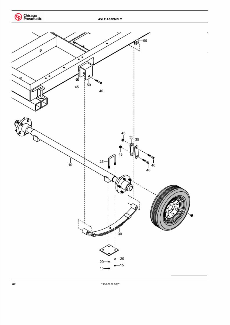
- 1310 0727 08 AXEL ASSEMBLY (From page 44)
10 1310 0725 93 AXLE
15 1310 0727 09 AXLE NUT 8
20 1310 0727 10 WASHER 8
25 1310 0727 11 U-BOLT 4
30 1310 0727 12 AXLE SPRING 2
35 1310 0727 13 SHACKLE STRAP 4
40 1310 0727 14 HEX BOLT 6
45 1310 0727 15 AXLE NUT 6
50 1310 0725 46 FRONT AXLE HANGER 2
55 1310 0725 47 REAR AXLE HANGER 2
REF PART NUMBER DESIGNATION QTY REF PART NUMBER DESIGNATION QT
1310 0727 08/01
AXLE ASSEMBLY

8/11/2019 Manual Partes Torre Iluminacion Chicago CPLT_M10.pdf
http://slidepdf.com/reader/full/manual-partes-torre-iluminacion-chicago-cpltm10pdf 50/56
50
- 1310 0727 67 WINCH ASSEMBLY (From page 37)
10 1310 0725 07 PULLEY 2
15 1310 0725 10 CABLE ASSEMBLY 1
20 1310 0725 24 WINCH 1
25 1310 0725 25 WINCH HANDLE 1
30 1310 0726 70 CABLE ASSEMBLY 6
35 1310 0728 49 WINCH HARDWARE ASSEMBLY 7
1310 0727 67_01
REF PART NUMBER DESIGNATION QTY REF PART NUMBER DESIGNATION QTY
1310 0727 67/01
TOWER WINCH ASSEMBLY

8/11/2019 Manual Partes Torre Iluminacion Chicago CPLT_M10.pdf
http://slidepdf.com/reader/full/manual-partes-torre-iluminacion-chicago-cpltm10pdf 51/56
5
GANG BOX ASSEMBLY
- 1310 0727 68 GANG BOX ASSEMBLY (From page 40)
10 1310 0725 03 COVER AND GASKET 1
15 1310 0725 33 GANG BOX 1
20 1310 0726 74 CLOSED END CONNECTOR 1
25 1310 0726 93 5 POSITION CONNECTOR 8
30 1310 0726 94 GROUND WIRE ASSEMBLY 1
HDW ASSEMBLY
- 1310 0727 69 HDW ASSEMBLY (From page 40)
35 1310 0725 91 CONDUIT NUT 3/4" 4
40 1310 0725 04 CORD GRIP 3/4" NPT 1
45 1310 0725 05 CORD GRIP 1/2" NPT 4
50 1310 0725 92 CONDUIT NUT 1/2" 1
1310 0727 68/01,1310 0727 69/01
REF PART NUMBER DESIGNATION QTY REF PART NUMBER DESIGNATION QT
1310 0727 68/01,1310 0727 69/01
GANG BOX ASSEMBLY, HDW ASSEMBLY

8/11/2019 Manual Partes Torre Iluminacion Chicago CPLT_M10.pdf
http://slidepdf.com/reader/full/manual-partes-torre-iluminacion-chicago-cpltm10pdf 52/56
52
- 1310 0725 37 FLOODLIGHT ASSEMBLY (From page 40)
10 1310 0726 43 LAMP 4
15 1310 0726 50 ELECTRICAL CABLE 1
20 1310 0725 05 CORD GRIP 4
25 1310 0725 21 LOCKWASHER 1
30 1310 0726 23 FLOODLIGHT ASSEMBLY 1
1310 0725 37_01
REF PART NUMBER DESIGNATION QTY REF PART NUMBER DESIGNATION QTY
1310 0725 37/01
FLOODLIGHT ASSEMBLY
8/11/2019 Manual Partes Torre Iluminacion Chicago CPLT_M10.pdf
http://slidepdf.com/reader/full/manual-partes-torre-iluminacion-chicago-cpltm10pdf 53/56
5
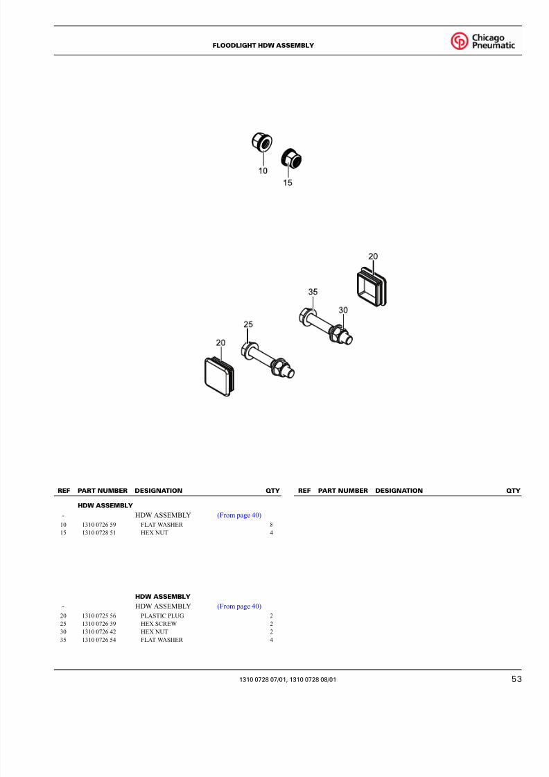
HDW ASSEMBLY
- HDW ASSEMBLY (From page 40)
10 1310 0726 59 FLAT WASHER 8
15 1310 0728 51 HEX NUT 4
HDW ASSEMBLY
- HDW ASSEMBLY (From page 40)
20 1310 0725 56 PLASTIC PLUG 2
25 1310 0726 39 HEX SCREW 2
30 1310 0726 42 HEX NUT 2
35 1310 0726 54 FLAT WASHER 4
201363
REF PART NUMBER DESIGNATION QTY REF PART NUMBER DESIGNATION QT
1310 0728 07/01, 1310 0728 08/01
FLOODLIGHT HDW ASSEMBLY

8/11/2019 Manual Partes Torre Iluminacion Chicago CPLT_M10.pdf
http://slidepdf.com/reader/full/manual-partes-torre-iluminacion-chicago-cpltm10pdf 54/56
54
- 1310 0726 84 GENERATOR (From page 41)
10 1310 0726 85 CAPACITOR 1
15 1310 0725 28 DIODE 1
1310 0726 84_01
REF PART NUMBER DESIGNATION QTY REF PART NUMBER DESIGNATION QTY
1310 0726 84/01
GENERATOR

8/11/2019 Manual Partes Torre Iluminacion Chicago CPLT_M10.pdf
http://slidepdf.com/reader/full/manual-partes-torre-iluminacion-chicago-cpltm10pdf 55/56

8/11/2019 Manual Partes Torre Iluminacion Chicago CPLT_M10.pdf
http://slidepdf.com/reader/full/manual-partes-torre-iluminacion-chicago-cpltm10pdf 56/56
“”
+7(800)700-55-97
+7(861)240-75-77
www.epomarket.ru