Manual Panel E Plus
36
POWER SYSTEMS, INC. ® Operator’s Manual “E-Plus” Option Control Panel This manual should remain with the unit.
-
Upload
roberto-sanchez-zapata -
Category
Documents
-
view
40 -
download
5
description
generac manual panel e plus
Transcript of Manual Panel E Plus

POWER SYSTEMS, INC.
®
Operator’s Manual“E-Plus” Option Control Panel
This manual should remain with the unit.

Generac® Power Systems, Inc.
Important Safety InstructionsE-Plus Option Control Panel
SAVE THESE INSTRUCTIONS – The manufacturer suggests that these rules for safe operation be copied and posted in potential hazard areas. Safety should be stressed to alloperators and potential operators of this equipment.! !
Study these SAFETY RULES carefully beforeinstalling, operating or servicing this equipment.Become familiar with this manual and all literaturepertaining to your generator set and related equip-ment. This equipment can operate safely, efficientlyand reliably only if it is properly installed, operatedand maintained. Many accidents are caused by failingto follow simple and fundamental rules or precau-tions.
Generac cannot possibly anticipate every possible circumstance that might involve a hazard. The warn-ings in this manual, and on tags and decalsaffixed to your equipment are, therefore, not all-inclusive. If you use a procedure, work method oroperating technique Generac does not specifically rec-ommend, you must satisfy yourself that it is safe for youand others. You also must make sure the procedure,work method or operating technique that you choosedoes not render the equipment unsafe.
GENERAL HAZARDS• For safety reasons, Generac recommends that this
equipment be installed and serviced by a GeneracAuthorized Service Dealer or other competent, quali-fied electrician or installation technician who is famil-iar with applicable codes, standards and regulations.The operator also must comply with all such codes,standards and regulations.
• When working on this equipment, remain alert at alltimes. Never work on the equipment when physical-ly or mentally fatigued.
• Inspect the equipment regularly, and promptly repairor replace all worn, damaged or defective parts usingonly factory-approved parts.
• Before performing any maintenance on the generatoror any related equipment, disable the generator toprevent accidental start-up. Remove the controlpanel fuse and then disconnect the battery cables byremoving the one indicated by a NEGATIVE, NEG or(–) first. To re-enable the generator, reconnect thebattery cables connecting the one indicated by aNEGATIVE, NEG or (–) last, then re-install the con-trol panel fuse.
ELECTRICAL HAZARDS• Generators produce dangerous electrical voltages
and can cause fatal electrical shock. Avoid contactwith bare wires, terminals, connections, etc., whilethe generator and related equipment are running.Ensure all appropriate covers, guards and barriersare in place before operating the equipment. Ifwork must be done around an operating unit,stand on an insulated, dry surface to reduce shockhazard.
• Do not handle any kind of electrical device whilestanding in water, while barefoot, or while hands orfeet are wet. DANGEROUS ELECTRICAL SHOCKMAY RESULT.
• If people must stand on metal or concrete whileinstalling, operating, servicing, adjusting or repairingthis equipment, place insulative mats over a drywooden platform. Work on the equipment only whilestanding on such insulative mats.
• Wire gauge sizes of electrical wiring, cables and cordsets must be adequate to handle the maximum elec-trical current (ampacity) to which they will be sub-jected.
• Before installing or servicing this equipment, makesure that all power voltage supplies are positivelyTURNED OFF at their source. Failure to do so willresult in hazardous and possibly fatal electricalshock.
• When installed with an automatic transfer switch, thegenerator may crank and start anytime withoutwarning. To prevent injuries caused by sudden start-up, disable the generator’s automatic start circuitbefore working on or around the unit. Then, place a“Do Not Operate” tag on the generator control paneland on the transfer switch.
• In case of accident caused by electric shock, imme-diately shut down the source of electrical power. Ifthis is not possible, attempt to free the victim fromthe live conductor. AVOID DIRECT CONTACT WITHTHE VICTIM. Use a nonconducting implement,such as a rope or board, to free the victim from thelive conductor. If the victim is unconscious, applyfirst aid and get immediate medical help.
• Never wear jewelry when working on this equipment.Jewelry can conduct electricity resulting in electricshock, or may get caught in moving componentscausing injury.
FIRE HAZARDS• For fire safety, the generator and related equipment
must be installed and maintained properly.Installation always must comply with applicablecodes, standards, laws and regulations. Adherestrictly to local, state and national electrical andbuilding codes. Comply with regulations theOccupational Safety and Health Administration(OSHA) has established. Also, ensure that theequipment is installed in accordance with the man-ufacturer’s instructions and recommendations.Following proper installation, do nothing thatmight alter a safe installation and render the unitin noncompliance with the aforementioned codes,standards, laws and regulations.
!!

Table of ContentsE-Plus Option Control Panel
Generac® Power Systems, Inc. 1
Safety Rules............................Inside Front CoverSection 1 — General Information ......................2OVERVIEW ............................................................2ENGINE CONTROL ................................................2E-PLUS OPTION CONTROL MODULE ..................2
Overview ......................................................................2Keypad ........................................................................3Display ........................................................................3
– Software Version Page ..........................................3– Generator Command Page ....................................3– Generator Status Page ..........................................3– Alarm Status Message Page ..................................3– Alarm Log Page ....................................................4– Instrumentation Page ............................................4– Parameter Entry Page ..........................................4
ALARMS ................................................................4ALARM PROCESSING............................................5
Input Alarm Functions ................................................5– Alarm Active ........................................................5
Alarm Type ..................................................................6– Status ..................................................................6– Warning – Non-Latched ........................................6– Alarm – Latched ..................................................6– Shutdown ............................................................6– Alarm Status ........................................................6– Alarm Message......................................................6
Other Alarms ..............................................................6– Overcrank ............................................................6– Coolant Level ........................................................6
PROGRAMMABLE PARAMETERS..........................6Preheat Enabled ..........................................................6Preheat Time ..............................................................6Start Time ..................................................................6Pause Time ..................................................................7Start Attempts ............................................................7Starter Disengage Speed..............................................7Hold Off Time..............................................................7Cool-down Time ..........................................................7Load Accept Voltage and Frequency ............................7Warm-up Time ............................................................7Voltage Scaling Factor ..................................................7Flywheel Teeth ............................................................7User-defined Output Functions ....................................7Analog Input Scaling Factors ......................................8Analog Input Messages ................................................8Analog Input Alarm Messages......................................8Analog Input Alarm Settings ........................................8Digital Input Alarm Settings ........................................8Oil Pressure Alarms ....................................................8Oil Temperature Alarms ..............................................8Coolant Temperature Alarms ......................................8Battery Voltage Alarms ................................................8Engine Speed Alarms ..................................................8Generator Voltage Alarms ............................................8
Generator Frequency Alarms ......................................9Fuel Level Alarms ........................................................9
E-PLUS PANEL MODEM SETUP PROCEDURE ..............9E-PLUS PANEL RS232 CABLES......................................9
Serial Communications ............................................10– Serial Communication Via Modem......................10– Remote Annunciator Panel..................................10
User Password ..........................................................10
ADDITIONAL PANEL COMPONENTS ..................10AC Voltmeter..............................................................10AC Ammeter ..............................................................10Frequency Meter ........................................................10Line-phase Selector Switch........................................10Alarm Horn ..............................................................10DC Panel Fuse............................................................10Emergency Stop Switch ............................................10
CHECKING/REPLACING THE E-PLUS PANEL CONTROL MODULE INTERNAL FUSE ............11
USER PROGRAMMABLE INPUTS........................11WIRING EXAMPLES ............................................12
User Programmable Input Number 1 ........................12User Programmable Inputs Numbers 2 and 3 ............12All User Programmable Inputs ..................................12
PROGRAMMING EXAMPLES ..............................13User Programmable Input Number 1 ........................13
Section 2 — Glossary ......................................14E CONTROL PANEL DEFINITIONS........................14Section 3 — Operation ....................................15OUTPUT FUNCTION TABLE ..................................15E-PLUS PANEL MASTER CONTROL BOX
CONFIGURATION SETTINGS............................16Engine Parameter Menu ............................................16System Alarm Menu ..................................................16Digital I/O Menu ........................................................17Analog Input Menu ....................................................17
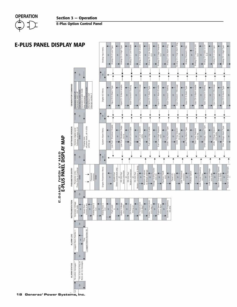
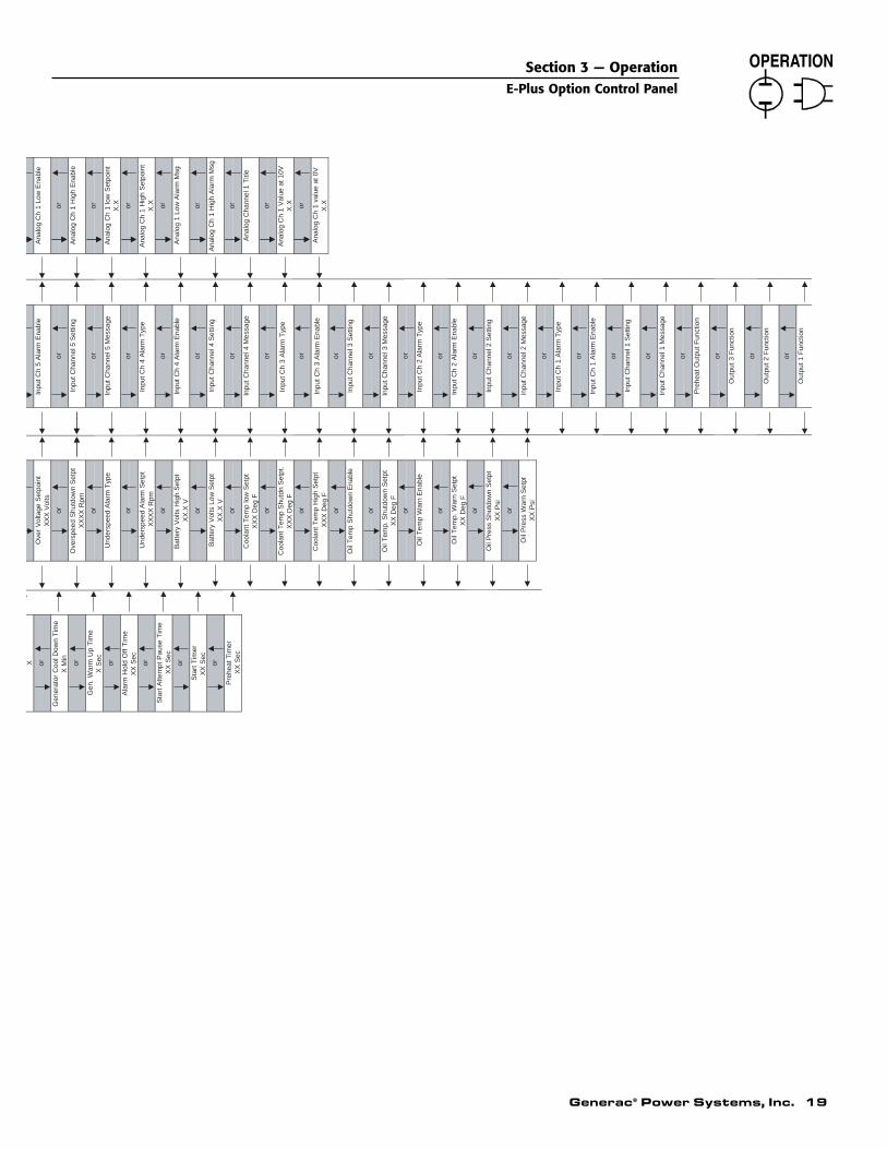
E-PLUS PANEL DISPLAY MAP ............................18Section 4 — Troubleshooting ..........................20Section 5 — Interconnection Diagram ............21Section 6 — Electrical Data ............................22Section 7 — Exploded Views & Parts Lists ......30Section 8 — Notes ..........................................32
AUTHORIZED SERVICE DEALER LOCATIONTo locate the nearest GENERAC AUTHORIZED
SERVICE DEALER, please call this number:
1-800-333-1322DEALER LOCATION INFORMATION
CAN BE OBTAINED AT THIS NUMBER.
OVERVIEWThe “E” option control panel is a programmableengine control and monitoring system. It allows theuser to customize the generator starting and runningsequence, monitor engine parameters and configurethe alarms. This can be done either through its owncontrol module, featuring liquid-crystal display(LCD) and keypad, or using a PC and RS232 serialcommunications. The module includes user pro-grammable inputs and outputs that allow it to be tai-lored to a vast range of applications. All of the setupinformation is stored in nonvolatile (permanent)memory.
ENGINE CONTROLThe module has a three-position selector switch thatselects between “Auto” mode, “Off” and “Manual” startmode. When the switch is in the OFF position, thegenerator will not start, and it will stop if it is running.When the switch is turned to MANUAL, the generatorwill start immediately and will continue to run untilthe switch is turned to the OFF position or a shut-down alarm is activated. With the switch in the AUTOposition, the generator will wait for either the remotestart contacts to close or for a start command to besent from the serial link. The generator will run untilthe remote start contacts open, a stop command issent down the serial link, a shutdown alarm is acti-vated or the switch is turned to the OFF position. Theremote start contacts always will have priority overthe serial link commands so that the serial link can-not stop the generator if the remote start contacts areclosed. When GenLink® software, which may beobtained from a Generac Authorized Service Dealer, isconnected to the E-Plus panel via modem, the panelwill monitor the connection to ensure that the line hasnot dropped. If the E-Plus panel detects that the linehas been dropped, it will disconnect the modem sothat it is ready for another incoming call. If the gener-ator had been started via the modem connection, thenit will be stopped immediately unless the remote startcontacts are closed or the generator is in manual.However, if the GenLink® software disconnectedcleanly (as a result of a user command) with the gen-erator running, then the generator will continue to runfor a another three hours unless it receives a stopcommand.
When a start command is received, the engine preheatwill be engaged, if it is selected. The user can programthe preheat to engage for a programmable time beforeengaging the starter motor, to engage while the engine isattempting to start, or to do both. In order to protectthe engine from trying to start while it is already run-ning (if the rpm sensor is damaged), an alarm is gener-ated if there is oil pressure when the start command issent. An alarm also is generated if there is a voltageoutput from the generator but the rpm sensor detectszero engine speed.
The user can program the length of time that the startermotor is engaged during a start attempt. After the firstattempt, the generator will pause for a programmablelength of time before the next attempt. The number ofattempts also is programmable, after which the failedto start alarm is activated.
The user can program a warm-up time that is activeafter the generator has started. This could be used inconjunction with a programmable relay output toinhibit the transfer switch from applying load untilthe generator is ready. The warm-up time can be setto zero if this function is not required. This timer isseparate from the alarm hold off timer, which allowsthe generator to run for a time before certain alarms(such as low oil pressure) are active.
If the generator is in the AUTO mode and a stop com-mand is received, a programmable cool-down timercan be used to keep the generator running with noload for a fixed time. This also can work in conjunc-tion with a relay output to inhibit the transfer switch.If the timer is set to zero, this function is disabled. Ifthe selector switch is turned to OFF, then the genera-tor will stop immediately without waiting for the cool-down time.
Certain alarm functions are designated as shutdownalarms. These alarms will stop the generator andinhibit it from starting until the alarm condition hascleared and the alarm has been reset.
E-PLUS OPTION CONTROL MODULE
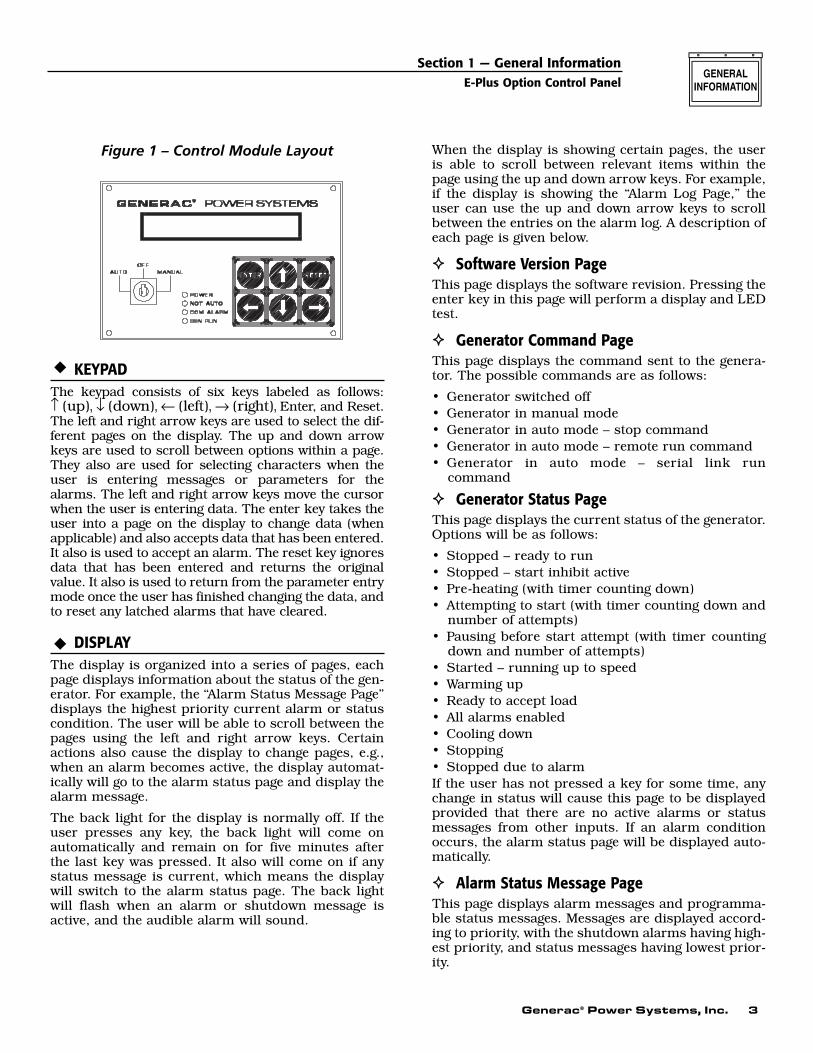
OVERVIEWThe LCD on the front of the module (Figure 1) featuresa 24-character by two-line display screen that will showone of seven pages. There is a keypad with six keys thatare used for operating the display and selecting the var-ious pages. A key activated switch allows the user toselect whether the generator is in the “Auto” mode, “Off”mode or “Manual” run mode. Four LEDs indicate thefollowing conditions:
• “Power” – Battery power is OK.• “Not Auto” – The generator is not in the automatic
mode.• “Com Alarm” – A common alarm condition has
occurred.• “Gen Run” – The generator is running.
NOTE:
The “Power” LED will go out immediately if thebattery voltage dips below the alarm limit, but thealarm will not be triggered unless the voltage islow for more than five minutes.
Section 1 — General InformationE-Plus Option Control Panel
2 Generac® Power Systems, Inc.
Generac® Power Systems, Inc. 3
Figure 1 – Control Module Layout
KEYPADThe keypad consists of six keys labeled as follows: ↑ (up), ↓ (down), ← (left), → (right), Enter, and Reset.The left and right arrow keys are used to select the dif-ferent pages on the display. The up and down arrowkeys are used to scroll between options within a page.They also are used for selecting characters when theuser is entering messages or parameters for thealarms. The left and right arrow keys move the cursorwhen the user is entering data. The enter key takes theuser into a page on the display to change data (whenapplicable) and also accepts data that has been entered.It also is used to accept an alarm. The reset key ignoresdata that has been entered and returns the originalvalue. It also is used to return from the parameter entrymode once the user has finished changing the data, andto reset any latched alarms that have cleared.
DISPLAYThe display is organized into a series of pages, eachpage displays information about the status of the gen-erator. For example, the “Alarm Status Message Page”displays the highest priority current alarm or statuscondition. The user will be able to scroll between thepages using the left and right arrow keys. Certainactions also cause the display to change pages, e.g.,when an alarm becomes active, the display automat-ically will go to the alarm status page and display thealarm message.
The back light for the display is normally off. If theuser presses any key, the back light will come onautomatically and remain on for five minutes afterthe last key was pressed. It also will come on if anystatus message is current, which means the displaywill switch to the alarm status page. The back lightwill flash when an alarm or shutdown message isactive, and the audible alarm will sound.
When the display is showing certain pages, the useris able to scroll between relevant items within thepage using the up and down arrow keys. For example,if the display is showing the “Alarm Log Page,” theuser can use the up and down arrow keys to scrollbetween the entries on the alarm log. A description ofeach page is given below.
Software Version PageThis page displays the software revision. Pressing theenter key in this page will perform a display and LEDtest.
Generator Command PageThis page displays the command sent to the genera-tor. The possible commands are as follows:
• Generator switched off• Generator in manual mode• Generator in auto mode – stop command• Generator in auto mode – remote run command• Generator in auto mode – serial link run
command
Generator Status PageThis page displays the current status of the generator.Options will be as follows:
• Stopped – ready to run• Stopped – start inhibit active• Pre-heating (with timer counting down)• Attempting to start (with timer counting down and
number of attempts)• Pausing before start attempt (with timer counting
down and number of attempts)• Started – running up to speed• Warming up• Ready to accept load• All alarms enabled• Cooling down• Stopping• Stopped due to alarmIf the user has not pressed a key for some time, anychange in status will cause this page to be displayedprovided that there are no active alarms or statusmessages from other inputs. If an alarm conditionoccurs, the alarm status page will be displayed auto-matically.
Alarm Status Message PageThis page displays alarm messages and programma-ble status messages. Messages are displayed accord-ing to priority, with the shutdown alarms having high-est priority, and status messages having lowest prior-ity.
Section 1 — General InformationE-Plus Option Control Panel
4 Generac® Power Systems, Inc.
If an alarm becomes active, the display will switch tothis page and display the highest priority alarm mes-sage. The back light and alarm LED will flash, and theaudible alarm will be activated. The user must pressthe enter key to accept the alarm, at which time theback light will be on continuously. If the alarm is non-latching, the alarm message will clear as soon as thecondition is cleared. If the alarm is a latching alarm,then the user must press the reset key to clear the mes-sage. Once a message has cleared, the display will showthe next priority alarm message.
After an alarm has been accepted, the user is able toscroll through other active alarm and messagescreens using the up and down arrow keys.
Alarm Log PageThis page displays the last 50 alarm messages. Whenthe user selects this page, it displays the latest alarmmessage. Pressing the up or down arrow keys willallow the user to scroll up and down the list of mes-sages.
Instrumentation PageThis page displays one of the analog signal values.Pressing the up or down arrow keys will scroll toother analog display screens.
Parameter Entry PageThis page allows the user to modify the various setpoints and programmable options. See the“Programmable Parameters” section of this manualfor more specific option information. The user mustpress the Enter key when this page is displayed andwill then be prompted for a password. The passwordis a six-digit number and the default value is 000000.However, the user will be able to change the pass-word. Digits will be selected using up and downarrow keys, and the cursor will be moved by the leftand right arrow keys. When the user presses theEnter key, the password will be checked. If the pass-word is correct, the display will show one of the dataentry screens.
There are four parameter entry menus: “EngineParameter,” “System Alarm,” “Digital I/O” and “AnalogInput.” The user will be able to scroll through the vari-ous parameters in each menu using the up and downarrow keys. The left and right arrow keys are used toswitch between the four menus. When a parameter thatrequires changing is displayed, the user presses theEnter key to enable data entry. A cursor will appear atthe first character that can be altered. The user canthen change the character using the up and down arrowkeys. The user can move to the next character or previ-ous character using the left and right arrow keys.Pressing the Enter key will accept the new setting.Pressing the Reset key will ignore the new setting.
If an alarm condition occurs when the user is enter-ing data, the data will be ignored, and the display willshow the alarm screen. If a status condition occurswhen data is being entered, the display will notchange.
Once the user has finished entering data by pressingthe Enter key, pressing the Reset key will allow theuser to select other pages using the left and rightarrow keys.
ALARMSAll analog channels have alarms associated withthem. There is also a coolant level alarm, an emer-gency stop alarm and eight user definable inputs thatcan be used to generate alarms. Alarms can be statusmessages, non-latching alarms, latching alarms orshutdown alarms. When a new alarm conditionoccurs, the alarm LED and the display back light willflash. Also, the alarm relay contacts will close (oper-ating the audible alarm), and the display will showthe alarm message. The user will be able to accept thealarm (turn off the audible alarm) from the keypad,and if the alarm condition has cleared, he or she alsowill be able to clear the alarm. Non-latching alarmswill clear themselves if the alarm condition is nolonger present. Latching alarms require the user toclear the alarm from the keypad even if the alarmcondition is no longer present. Shutdown alarms aresimilar to latched alarms, but they also cause thegenerator to stop and will not allow it to start againuntil the key switch has been turned to the OFF posi-tion to reset the alarm. Status messages are similarto non-latching alarms except that they do not acti-vate the alarm relay or the alarm LED and are notrecorded on the alarm log.
Alarms can be always active, immediately active whenthe generator is commanded to run, or active afterthe hold off timer has expired. This timer delays theoperation of certain alarms until a programmabletime after the engine has started. Some alarms allowthe user to define the type of alarm and when it isactive.
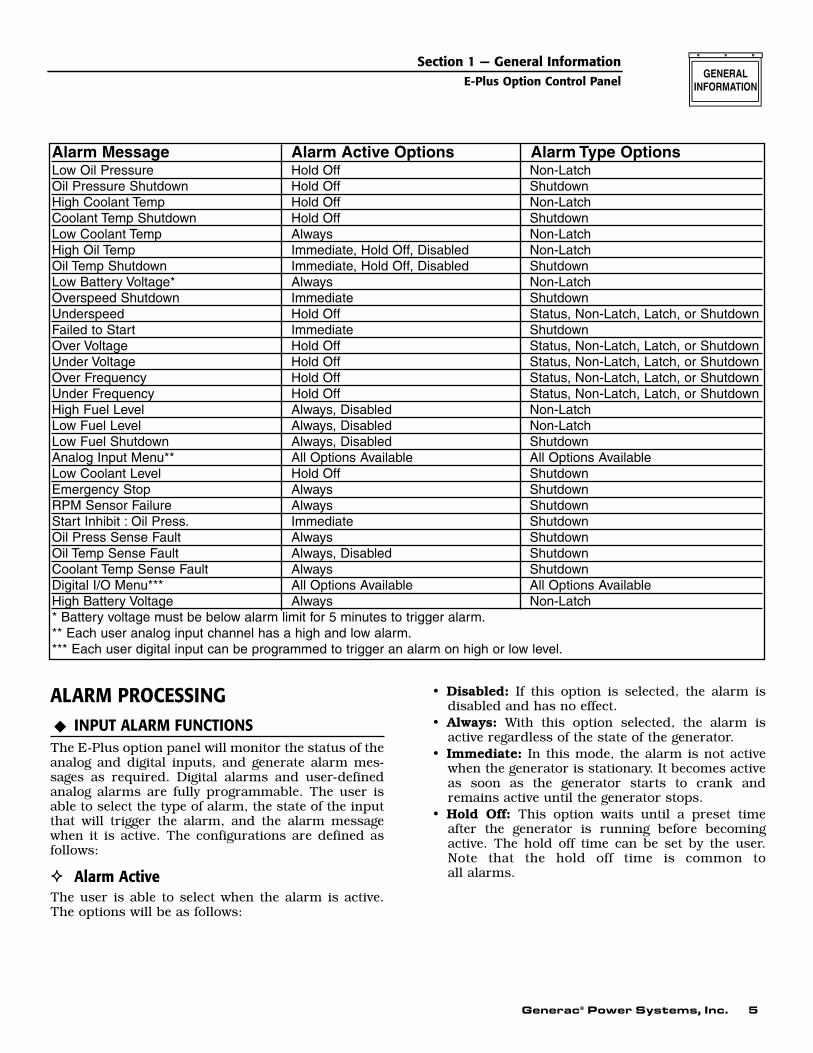
The following chart is a summary of the alarms andthe programmable options:
Section 1 — General InformationE-Plus Option Control Panel
Generac® Power Systems, Inc. 5
ALARM PROCESSINGINPUT ALARM FUNCTIONS
The E-Plus option panel will monitor the status of theanalog and digital inputs, and generate alarm mes-sages as required. Digital alarms and user-definedanalog alarms are fully programmable. The user isable to select the type of alarm, the state of the inputthat will trigger the alarm, and the alarm messagewhen it is active. The configurations are defined asfollows:
Alarm ActiveThe user is able to select when the alarm is active.The options will be as follows:
• Disabled: If this option is selected, the alarm isdisabled and has no effect.
• Always: With this option selected, the alarm isactive regardless of the state of the generator.
• Immediate: In this mode, the alarm is not activewhen the generator is stationary. It becomes activeas soon as the generator starts to crank andremains active until the generator stops.
• Hold Off: This option waits until a preset timeafter the generator is running before becomingactive. The hold off time can be set by the user.Note that the hold off time is common to all alarms.
Section 1 — General InformationE-Plus Option Control Panel
Alarm Message Alarm Active Options Alarm Type OptionsLow Oil Pressure Hold Off Non-LatchOil Pressure Shutdown Hold Off ShutdownHigh Coolant Temp Hold Off Non-LatchCoolant Temp Shutdown Hold Off ShutdownLow Coolant Temp Always Non-LatchHigh Oil Temp Immediate, Hold Off, Disabled Non-LatchOil Temp Shutdown Immediate, Hold Off, Disabled ShutdownLow Battery Voltage* Always Non-LatchOverspeed Shutdown Immediate ShutdownUnderspeed Hold Off Status, Non-Latch, Latch, or ShutdownFailed to Start Immediate ShutdownOver Voltage Hold Off Status, Non-Latch, Latch, or ShutdownUnder Voltage Hold Off Status, Non-Latch, Latch, or ShutdownOver Frequency Hold Off Status, Non-Latch, Latch, or ShutdownUnder Frequency Hold Off Status, Non-Latch, Latch, or ShutdownHigh Fuel Level Always, Disabled Non-LatchLow Fuel Level Always, Disabled Non-LatchLow Fuel Shutdown Always, Disabled ShutdownAnalog Input Menu** All Options Available All Options AvailableLow Coolant Level Hold Off ShutdownEmergency Stop Always ShutdownRPM Sensor Failure Always ShutdownStart Inhibit : Oil Press. Immediate ShutdownOil Press Sense Fault Always ShutdownOil Temp Sense Fault Always, Disabled ShutdownCoolant Temp Sense Fault Always ShutdownDigital I/O Menu*** All Options Available All Options AvailableHigh Battery Voltage Always Non-Latch* Battery voltage must be below alarm limit for 5 minutes to trigger alarm.** Each user analog input channel has a high and low alarm.*** Each user digital input can be programmed to trigger an alarm on high or low level.
6 Generac® Power Systems, Inc.
ALARM TYPE
StatusThis type of alarm will display a message on thescreen. The message will not be logged. This is thelowest priority of alarm types.
Warning – Non-LatchedThis type of warning will activate the audible alarm,and flash the alarm LED and display back light. Theassociated message will be displayed on the screen.When the user accepts the warning (by pressing theEnter key), the back light will stop flashing, and thealarm LED will be on continuously. The message will bedisplayed on the alarm screen, but the user will be ableto scroll through other screens. The LED and messagewill clear when the warning condition clears. This typeof warning is logged.
Alarm – LatchedThis type of alarm will act similarly to the non-latchedwarning, except that the alarm does not clear when thealarm condition clears. When the alarm conditionoccurs, the audible alarm sounds, the LED and backlight flash as before, and the user must accept thealarm to stop them. The alarm will continue to be dis-played on the screen even after the alarm condition hascleared. The user must either press the Reset key orturn the key switch to the OFF position to clear thealarm after the alarm condition has cleared. This typeof alarm is logged.
ShutdownThis type of alarm will act similar to the latchedalarm, but it also will stop the engine when the alarmcondition occurs. It can be reset only by turning thekey switch to the OFF position. All shutdown alarmsare latching, and this type of alarm is logged.
Alarm StatusThis is the value at which the alarm is active. For ana-log alarms, it is a number corresponding to the alarmlimit. Digital alarms are either “normally open” or“normally closed,” and an alarm is generated whenthe input is not in the normal state.
Alarm MessageEach alarm will have a message associated with it. Theanalog alarm messages will be preset, and the digitalalarm messages and user-defined analog messages willbe entered via the keypad or the serial link.
OTHER ALARMS
OvercrankThis alarm is unlike other alarms as it is not associ-ated with an analog or digital signal. The user is ableto define the number of crank attempts, the length ofeach crank attempt and the rest time betweencranks. After the last attempt has been made, anovercrank alarm will be generated. The user will thenbe unable to disable this alarm or alter the alarmmessage.
Coolant LevelThis alarm is generated by the coolant level detector.This device senses whether coolant is present or not.It has no user-definable level setting and is a shut-down alarm that is active after the hold off time.There are no user-definable parameters for thisalarm.
PROGRAMMABLE PARAMETERSThe E-Plus option panel allows the user to configurevarious options to control the generator starting andstopping cycles, and the way that the alarms operate.Parameters are entered either from the control mod-ule or via the serial link. A description of the pro-grammable parameters follows:
PREHEAT ENABLEDThis parameter determines how the preheat functionworks. The preheat can be fully disabled, enabledbefore starting only (for the duration of the preheattime), or before and during starting (for the durationof the preheat time and also while the starter isengaged). Note that if the user wishes to engage thepreheat during starting, but not to have a preheatbefore starting, it is possible to set the preheat timeto zero.
PREHEAT TIMEWhen a start command is received, some enginesrequire preheating before the generator attempts tostart. When the preheat function is enabled, thisparameter allows the user to determine the time thatthe preheat contact closes before activating thestarter solenoid.
START TIMEOnce a start command has been received and the preheat time has expired (if enabled), the startersolenoid will be engaged. This parameter allows theuser to determine how long the starter solenoid isengaged before the start attempt is regarded as hav-ing failed. If the generator does not start within thistime, the generator will wait for a preset time beforeattempting to start again. The user also can programthe number of start attempts the generator tries.
Section 1 — General InformationE-Plus Option Control Panel
Generac® Power Systems, Inc. 7
PAUSE TIMEIf the generator does not start within the pro-grammed start time, it will pause before trying tostart again. This parameter determines the length ofthat pause.
START ATTEMPTSThis parameter determines the number of times thatthe generator tries to start. If the generator has notstarted after this number of attempts, an alarm isgenerated.
STARTER DISENGAGE SPEEDWhile the starter is engaged, the engine speed is mon-itored. Once it reaches this value, the starter motor isdisengaged, and the engine is regarded as havingstarted.
HOLD OFF TIMEOnce the engine has started, some alarm functions(such as low oil pressure and under speed) are notactivated immediately since the engine must be giventime to reach a stable condition. This parameterdetermines the time that elapses before the hold offalarms are activated.
COOL-DOWN TIMEIt is sometimes desirable to run the generator for agiven time with no load before stopping to allow theengine to cool down. This parameter determines thelength of time that the generator continues to runafter a stop command is sent in AUTO mode. Notethat if the key switch is turned to the OFF positionwhen the generator is running, it will stop immedi-ately regardless of this setting. This value also shouldbe set to zero if this function is controlled by thetransfer switch.
LOAD ACCEPT VOLTAGE AND FREQUENCYOnce the generator has started, the voltage and fre-quency will ramp up until they reach the values atwhich the generator can accept load. These parame-ters allow the user to set the values. The valuesshould be set slightly lower than the nominal valuesto allow for a margin of error in the regulator andgovernor settings. Once the values have beenreached, the warm-up timer is started.
WARM-UP TIMESome applications require that the generator isallowed to run for a given time before a load isapplied. This parameter allows the user to set thattime. Note that if this function is controlled elsewhere(e.g., within a transfer switch), this time should be setto zero. The generator is ready to accept load whenthis timer expires. This parameter can be assigned toan output relay.
VOLTAGE SCALING FACTORThe voltage scaling factor is used to scale the sensingvoltage applied to CON4-4 and CON4-6.
On generators manufactured prior to the secondquarter of 2000: Sensing voltage was measured fromline-to-line, so the scaling factor was primarily set to1.0. On generators manufactured starting the secondquarter of 2000: Sensing voltage is measured fromthe frequency meter, in this case the scaling factor isused so the “E” panel displays line-to-line voltage.This scaling factor can also be used to “calibrate” the“E” panel display.
FLYWHEEL TEETHThis parameter holds the number of flywheel teeth.This value is used to determine the engine speedfrom the magnetic pickup signal.
USER-DEFINED OUTPUT FUNCTIONSThere are three user-defined outputs, and the preheatoutput also can be used as a user-defined output if thepreheat function is disabled. Each output can be pro-grammed to signal that an alarm is active, to indicateone specific alarm or input condition, to indicate thestatus of the key switch, or to indicate the current sta-tus of the generator. These relay contacts can be usedto switch up to 30 volts AC or DC at 1 amp.
NOTE:
See the “Output Function Table” on Page 15 andthe E-Plus panel Display Map on pages 18-19 formore detail.
Example: Program User output #2 to be active onany generator alarm shutdown.
1. Press the left or right arrow key until the displayreads “Paramenter Entry” and press ENTER.
2. Enter the password and press ENTER.3. Use the left and right arrow keys to find the
“Digital I/O Menu”.4. Use the up and down arrow keys to locate
“Output 2 Function”. The bottom line of the dis-play will read the current setting.
5. Press ENTER. Use the up and down arrows toscroll through the list until “Generator AlarmShutdown” is displayed in the bottom line.
6. Press the ENTER KEY. User Output #2 is nowprogrammed to become active (relay energized)on any generator shutdown alarm.
7. Press RESET. This exits the programming modeand returns back to the parameter entry screen.
Section 1 — General InformationE-Plus Option Control Panel

8 Generac® Power Systems, Inc.
ANALOG INPUT SCALING FACTORSThe two user-defined analog inputs can be scaled sothat the display uses meaningful values rather than thevoltage level at the input. The user enters the value tobe displayed when the input voltage is zero and when itis at the maximum value. (An analog input to the E-Pluspanel is a voltage sourced input with a zero to 10-voltrange.) All alarm settings are based on this scaling, andthe instrumentation display shows the input valuebased on this scaling too.
ANALOG INPUT MESSAGESThis is a message up to 24 characters long that is dis-played on the instrumentation display when the cor-responding value is being shown.
ANALOG INPUT ALARM MESSAGESThere is a user-definable message for each alarmcondition on each analog input. This message isshown on the alarm display when the alarm condi-tion is active and is stored in the alarm log.
ANALOG INPUT ALARM SETTINGSEach analog input has two alarms associated with it.One is activated when the input value is higher thanthe high set point, and the other is active when theinput is lower than the low set point. The user alsocan define when the alarm is active (or disable it) andthe severity of the alarm (from simply displaying astatus message to shutting down the generator – see“Alarm Processing” on Page 5).
DIGITAL INPUT ALARM SETTINGSEach digital input also can generate an alarm. Theuser can program the alarm message, the input statethat generates the alarm, when the alarm is active,and the alarm type. A digital input to the E-Plus panelis NOT a voltage sourced input, but a dry contact clo-sure to ground. Voltage never should be sourced to adigital input. The signal options to a digital input areas follows:
• Open: This signal is an open circuit.• Closed: This signal is a contact closure to ground.
*NOTE:
For oil pressure, oil temperature and coolant tem-perature, the E-Plus panel will check to see ifthese inputs are either open circuit or short cir-cuit which would indicate a faulty sender or faultywiring to the sender.
If this type of fault condition exists the E-Pluspanel will activate the alarm output and displayone of the following message:
• Oil Pressure Sense Fault• Oil Temp Sense Fault• Coolant Temp Sense Fault
OIL PRESSURE ALARMS (*SEE NOTE)
The oil pressure input has two associated alarmfunctions. The pre-low oil pressure warning is a non-latched, hold off alarm with a user-definable setpoint. The low oil pressure shutdown is a shutdown,hold off alarm with a user-definable set point. Theshutdown alarm set point should be the lowest of thetwo settings so that the user will have some warningof a low oil condition before the generator is shutdown.
OIL TEMPERATURE ALARMS (*SEE NOTE)
The oil temperature has a non-latched warning and ashutdown alarm associated with it. The set points areprogrammable, and the alarms can be immediate,hold off or disabled.
COOLANT TEMPERATURE ALARMS (*SEE NOTE)
The coolant temperature input has three associatedalarms. The pre-high coolant temperature alarm is anon-latched, hold-off alarm. The high coolant tem-perature alarm is a shutdown, hold-off alarm. Thelow coolant temperature warning is a non-latched,always active alarm. set points for each alarm areprogrammable.
BATTERY VOLTAGE ALARMSThe low battery voltage warning set point is pro-grammable. The warning will be activated if the bat-tery voltage is below this value for more than fiveminutes. This is a non-latched, always active alarm.Note that the “Power” LED on the front panel is extin-guished immediately if the battery voltage is less thanthis value. The high battery voltage alarm set point isalso programmable. The warning is active immedi-ately when the battery voltage is higher than thisvalue.
ENGINE SPEED ALARMSThe user can program the overspeed and the under-speed alarm. The overspeed alarm is an immediateshutdown alarm. Underspeed is a hold off alarm thatcan either be non-latched, latched or shutdown.
GENERATOR VOLTAGE ALARMSAn alarm can be generated for high voltage and lowvoltage. The set points are user-definable, and thealarms can be either non-latching, latching or shut-down.
Section 1 — General InformationE-Plus Option Control Panel
Generac® Power Systems, Inc. 9
GENERATOR FREQUENCY ALARMSAn alarm can be generated for high frequency andlow frequency. The set points are user-definable, andthe alarms can be either non-latching, latching orshutdown.
FUEL LEVEL ALARMSAlarms can be generated by an optional fuel level sen-sor. The high fuel level warning is non-latching. Thereis also a low fuel level warning that is non-latchingand a low fuel shutdown alarm. Each of these alarmshas a set point and can be always active or disabled.
E-PLUS PANEL MODEM SETUPPROCEDURE
NOTE:
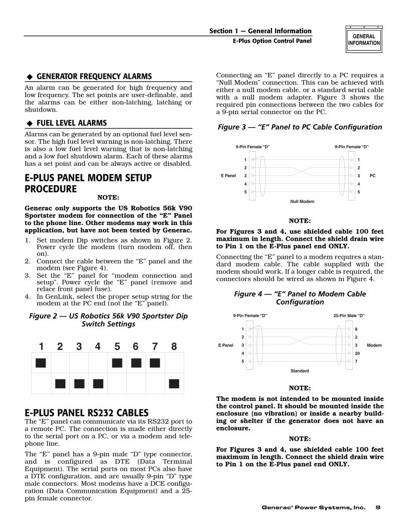
Generac only supports the US Robotics 56k V90Sportster modem for connection of the “E” Panelto the phone line. Other modems may work in thisapplication, but have not been tested by Generac.1. Set modem Dip switches as shown in Figure 2.
Power cycle the modem (turn modem off, thenon).
2. Connect the cable between the “E” panel and themodem (see Figure 4).
3. Set the “E” panel for “modem connection andsetup”. Power cycle the “E” panel (remove andrelace front panel fuse).
4. In GenLink, select the proper setup string for themodem at the PC end (not the “E” panel).
Figure 2 — US Robotics 56k V90 Sportster DipSwitch Settings
E-PLUS PANEL RS232 CABLESThe “E” panel can communicate via its RS232 port toa remote PC. The connection is made either directlyto the serial port on a PC, or via a modem and tele-phone line.
The “E” panel has a 9-pin male “D” type connector,and is configured as DTE (Data TerminalEquipment). The serial ports on most PCs also havea DTE configuration, and are usually 9-pin “D” typemale connectors. Most modems have a DCE configu-ration (Data Communication Equipment) and a 25-pin female connector.
Connecting an “E” panel directly to a PC requires a“Null Modem” connection. This can be achieved witheither a null modem cable, or a standard serial cablewith a null modem adapter. Figure 3 shows therequired pin connections between the two cables fora 9-pin serial connector on the PC.
Figure 3 — “E” Panel to PC Cable Configuration
NOTE:
For Figures 3 and 4, use shielded cable 100 feetmaximum in length. Connect the shield drain wireto Pin 1 on the E-Plus panel end ONLY.
Connecting the “E” panel to a modem requires a stan-dard modem cable. The cable supplied with themodem should work. If a longer cable is required, theconnectors should be wired as shown in Figure 4.
Figure 4 — “E” Panel to Modem CableConfiguration
NOTE:
The modem is not intended to be mounted insidethe control panel. It should be mounted inside theenclosure (no vibration) or inside a nearby build-ing or shelter if the generator does not have anenclosure.
NOTE:
For Figures 3 and 4, use shielded cable 100 feetmaximum in length. Connect the shield drain wireto Pin 1 on the E-Plus panel end ONLY.
Section 1 — General InformationE-Plus Option Control Panel

10 Generac® Power Systems, Inc.
Section 1 — General InformationE-Plus Option Control Panel
SERIAL COMMUNICATIONS
Serial Communication Via Modem(Refer to the Genlink Manual)
The control panel has the ability to communicate to aPC via an RS232 serial port. The PC software will beable to interrogate the module, and the user also will beable to program the parameters on the PC and down-load them to the module. The user will be able to startand stop the generator if it is in AUTO mode.
The module does not have a built-in modem.However, software will include the ability to interfacewith an external modem. The user can initialize themodem from the panel. Generac offers a remoteannunciator which allows the E-Plus panel to com-municate with both a modem and a remote annunci-ator. See the Remote Annunciator Panel manual for acomplete description of these panels.
Remote Annunciator Panel(Refer to the Remote Annunciator and Remote Relaymanuals.)
The serial connections can be configured to allow thecontrol panel to connect to a remote annunciator/remote relay panel, which is configured as RS485, tomeet NFPA 110. Only one communication port isavailable for either a modem or remote annunciator.
USER PASSWORDThe user can set the password. This is a six-digitnumber and is initially set to 000000.
ADDITIONAL PANEL COMPONENTSIn addition to the control module, the E-Plus optionpanel contains the following components (see Figure6):
AC VOLTMETERThis meter indicates the generator AC output voltage.To determine the nominal rated AC voltage of theunit, refer to the unit’s data plate.
NOTE:
Some generators are reconnectable to a variety ofvoltages. Some units may be equipped with arotary “Voltage Selector Switch.” Be sure to readthe “Generator AC Lead Connections” section inthe Owner’s Manual.
AC AMMETERThis meter indicates the current draw of connectedelectrical loads, in amps. Also see “Line-phaseSelector Switch.” For continuous operation, neverexceed the rated maximum continuous currentcapacity of the generator.
FREQUENCY METERThis meter indicates the generator’s AC output fre-quency in “Hertz” (cycles per second).
LINE-PHASE SELECTOR SWITCHThis four-position switch permits selection of eitherline-to-line or line-to-neutral readings on the panelvoltmeter and ammeter. Switch positions are as fol-lows:
Figure 6 – E-Plus Option Panel Components
ALARM HORNThis horn sounds an audible warning when an alarmcondition exists. See the “Alarms” section for furtherinformation.
DC PANEL FUSEThis 15 amp AGC fuse protects the panel compo-nents. This fuse is not to be confused with the controlmodule internal fuse discussed in “Checking/Replacing the E-Plus panel Control Module InternalFuse.”
EMERGENCY STOP SWITCHWhen pressed, this switch will automatically shutdown the entire generator set. The operator musttwist the switch to pop out to its original position toreset it and allow for generator operation.
✧✧
Switch Single-phase Units Three-phase units1 Line E1 to Neutral Line E1 to E2
2 Line E3 to Neutral Line E2 to E3
3 Line E1 to E3 Line E3 to E1
OFF No Reading No Reading
Generac® Power Systems, Inc. 11
CHECKING/REPLACING THE E-PLUS PANELCONTROL MODULE INTERNAL FUSETypically, the main indication of fuse failure is theabsence of any illuminated front panel LEDs (even withthe key in the OFF position, the “Power” LED will beilluminated) and no text visible on the module display.It should be noted however, that these conditions canexist if either:
a. The generator start battery is dead (less than five-volts) or disconnected.
b. The main panel fuse (15 amp AGC) is blown.c. The battery supply wires (#220 and #0) to the
panel control module are open circuit (disconnect-ed).
d. The “Power” connector (CON4) is disconnectedfrom the rear of the control module.
e. The generator start battery connections have beenreversed. Reversal of the battery connections WILLblow the internal fuse and is the most likely reasonfor its failure.
Before removing or disconnecting the E-Plus panel con-trol module, check that none of the above conditions(“a” through “e”) exist.
If it is believed that the problem lies with the controlmodule:
1. Disconnect the generator start battery.2. Unplug all four wire harnesses from the back of the
control module.3. Loosen, then detach, the two retaining clips secur-
ing the control module and remove the module.4. Using a multimeter (e.g., Fluke 87) set to the diode
range, measure between pins 1 (BAT+) and 2(BAT-) of connector CON4 on the module.• With the positive meter lead connected to pin 2
and the negative lead to pin 1, the meter shouldread between 0.4 and 0.6 volts, which indicatesthat the internal fuse is OK.
• Reversing the meter leads would give a slowlyincreasing voltage reading on the meter, whichalso indicates a good fuse.
• An open circuit fuse will give an open circuitmeter reading (.OL on Fluke 87).
If the meter reads open circuit:5. Remove the four phillips head screws retaining the
rear cover of the control module.3. Open the back of the control module.4. Locate the internal printed-circuit board mounted
fuse, which is behind and to the left of CON4.5. Remove the white plastic cover from the fuse holder
and remove the fuse.6. If the fuse has blown, replace the fuse (use a 5A
5x20mm Slo-Blo fuse, part number 0A5705),reassemble the control module, and reinstall the con-trol module and its connections.
7. Reconnect the generator start battery and check ifthe control module now functions.
If the fuse blows again, or was not blown when the mod-ule was opened, or the module still does not function,the E-Plus panel control module must be replaced.
USER PROGRAMMABLE INPUTSThe E-Plus panel has eight (8) user programmableinputs. These inputs can be used for annunciation, pre-alarm, or shutdown alarms. Four of the inputs, BatteryCharge Fail, Gen Power, Line Power, and ProgrammableInput 4 are set up to annunciate on the control paneldisplay and at the optional 20 Light RemoteAnnunciator (Programmable Input 4 will light the unla-beled “spare” LED). These four inputs can be used forother connections if a remote annunciator is not used.The other four inputs, if utilized, will annunciate at thecontrol panel only.
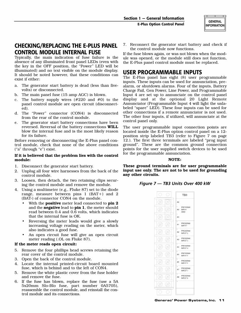
The user programmable input connection points arelocated inside the E-Plus option control panel on a 12-position strip labeled TB3 (refer to Figure 7 on page12.). The first three terminals are labeled “prog inputground”. These are the common ground connectionpoints for the user supplied switch devices to be usedfor the programmable annunciation.
NOTE:
These ground terminals are for user programmableinput use only. The are not to be used for groundingany other circuits.
Figure 7 — TB3 Units Over 400 kW
A0 INPUT
10
INPUT 8
INPUT 7PROGRAM
PROGRAMA8
A7
11
12
INPUT 6
INPUT 5
INPUT 4
INPUT 3
INPUT 2
PROGRAMINPUT 1
PROGRAM
PROGRAM
PROGRAM
PROGRAM
PROGRAMA6
A5
A4
A3
A2
A1
A0
GND3
4
5
6
7
8
9
PROGRAM
A0
1
2
TB3
Section 1 — General InformationE-Plus Option Control Panel
12 Generac® Power Systems, Inc.
The remaining eight terminals on TB3 are for the “pos-itive” side of each user programmable input switch cir-cuit. These eight terminals have a five VDC potentialavailable in an open circuit condition (whether the con-trol panel key switch is in the off, manual, or auto posi-tion). The inputs can be programmed to annunciateupon either an open circuit condition (five VDC poten-tial at the terminal) or a grounded condition (zero VDCpotential at the terminal). This voltage state is deter-mined by the user supplied switch either opening orclosing to cause an annunciation.
Program set-up for the user programmable inputs iscarried out in the Digital I/O Menu of the E module(please refer to the Display Map on pages 18-19). Eachof the eight inputs has four parameters in which specif-ic options must be selected to make the annunciationfunction properly. These four parameters are labeledInput Channel Message, Input Channel Setting, InputChannel Alarm Enable, and Input Channel Alarm Type.Following is a brief description of each:
• Input Channel Message — for selecting letters andnumbers to spell out what the display will read uponactivation of that specific input.
• Input Channel Setting — for selecting whetherannunciation should activate upon that specific cir-cuit opening or closing to ground.
• Input Channel Alarm Enable — for enabling or dis-abling annunciation function of that specific input.Also, if enabled, for selecting when annunciation willbe active. The choices are: Disabled, Always,Immediate and Hold-off. See E Control PanelDefinitions on page 14.
• Input Channel Alarm Type — for selecting the type ofalarm annunciation and the effect it has on the gen-erators control system. The four choices are: Status,Non-latched, Latched and Shutdown. See E ControlPanel Definitions on page 14.
WIRING EXAMPLESUSER PROGRAMMABLE INPUT NUMBER 1
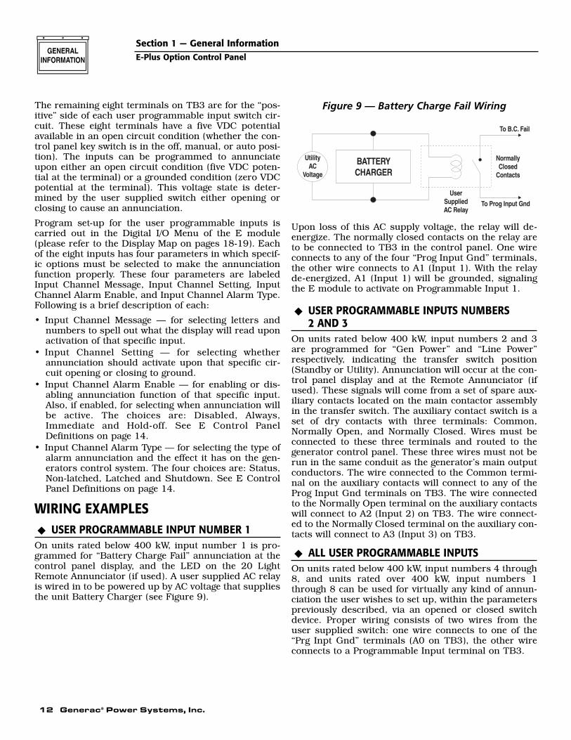
On units rated below 400 kW, input number 1 is pro-grammed for “Battery Charge Fail” annunciation at thecontrol panel display, and the LED on the 20 LightRemote Annunciator (if used). A user supplied AC relayis wired in to be powered up by AC voltage that suppliesthe unit Battery Charger (see Figure 9).
Figure 9 — Battery Charge Fail Wiring
Upon loss of this AC supply voltage, the relay will de-energize. The normally closed contacts on the relay areto be connected to TB3 in the control panel. One wireconnects to any of the four “Prog Input Gnd” terminals,the other wire connects to A1 (Input 1). With the relayde-energized, A1 (Input 1) will be grounded, signalingthe E module to activate on Programmable Input 1.
USER PROGRAMMABLE INPUTS NUMBERS2 AND 3
On units rated below 400 kW, input numbers 2 and 3are programmed for “Gen Power” and “Line Power”respectively, indicating the transfer switch position(Standby or Utility). Annunciation will occur at the con-trol panel display and at the Remote Annunciator (ifused). These signals will come from a set of spare aux-iliary contacts located on the main contactor assemblyin the transfer switch. The auxiliary contact switch is aset of dry contacts with three terminals: Common,Normally Open, and Normally Closed. Wires must beconnected to these three terminals and routed to thegenerator control panel. These three wires must not berun in the same conduit as the generator’s main outputconductors. The wire connected to the Common termi-nal on the auxiliary contacts will connect to any of theProg Input Gnd terminals on TB3. The wire connectedto the Normally Open terminal on the auxiliary contactswill connect to A2 (Input 2) on TB3. The wire connect-ed to the Normally Closed terminal on the auxiliary con-tacts will connect to A3 (Input 3) on TB3.
ALL USER PROGRAMMABLE INPUTSOn units rated below 400 kW, input numbers 4 through8, and units rated over 400 kW, input numbers 1through 8 can be used for virtually any kind of annun-ciation the user wishes to set up, within the parameterspreviously described, via an opened or closed switchdevice. Proper wiring consists of two wires from theuser supplied switch: one wire connects to one of the“Prg Inpt Gnd” terminals (A0 on TB3), the other wireconnects to a Programmable Input terminal on TB3.
◆
◆
◆
Section 1 — General InformationE-Plus Option Control Panel
Generac® Power Systems, Inc. 13
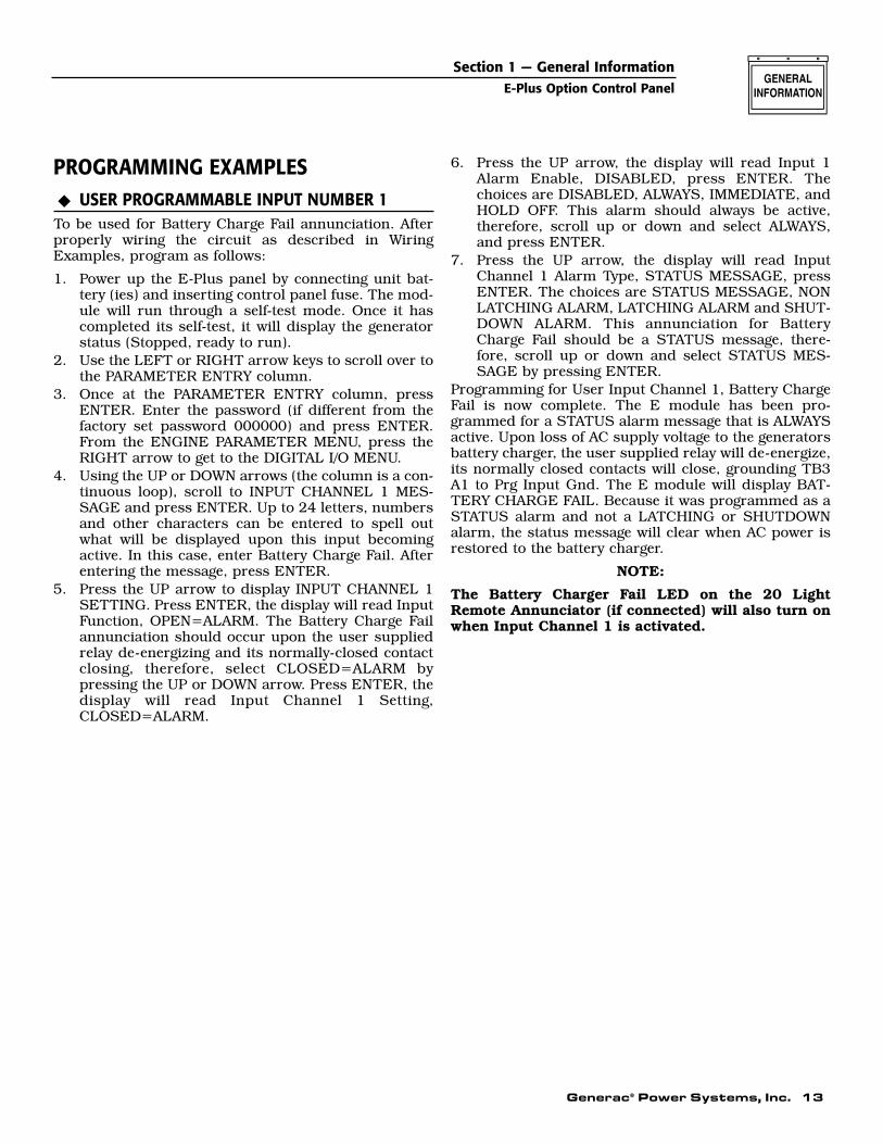
PROGRAMMING EXAMPLESUSER PROGRAMMABLE INPUT NUMBER 1
To be used for Battery Charge Fail annunciation. Afterproperly wiring the circuit as described in WiringExamples, program as follows:
1. Power up the E-Plus panel by connecting unit bat-tery (ies) and inserting control panel fuse. The mod-ule will run through a self-test mode. Once it hascompleted its self-test, it will display the generatorstatus (Stopped, ready to run).
2. Use the LEFT or RIGHT arrow keys to scroll over tothe PARAMETER ENTRY column.
3. Once at the PARAMETER ENTRY column, pressENTER. Enter the password (if different from thefactory set password 000000) and press ENTER.From the ENGINE PARAMETER MENU, press theRIGHT arrow to get to the DIGITAL I/O MENU.
4. Using the UP or DOWN arrows (the column is a con-tinuous loop), scroll to INPUT CHANNEL 1 MES-SAGE and press ENTER. Up to 24 letters, numbersand other characters can be entered to spell outwhat will be displayed upon this input becomingactive. In this case, enter Battery Charge Fail. Afterentering the message, press ENTER.
5. Press the UP arrow to display INPUT CHANNEL 1SETTING. Press ENTER, the display will read InputFunction, OPEN=ALARM. The Battery Charge Failannunciation should occur upon the user suppliedrelay de-energizing and its normally-closed contactclosing, therefore, select CLOSED=ALARM bypressing the UP or DOWN arrow. Press ENTER, thedisplay will read Input Channel 1 Setting,CLOSED=ALARM.
6. Press the UP arrow, the display will read Input 1Alarm Enable, DISABLED, press ENTER. Thechoices are DISABLED, ALWAYS, IMMEDIATE, andHOLD OFF. This alarm should always be active,therefore, scroll up or down and select ALWAYS,and press ENTER.
7. Press the UP arrow, the display will read InputChannel 1 Alarm Type, STATUS MESSAGE, pressENTER. The choices are STATUS MESSAGE, NONLATCHING ALARM, LATCHING ALARM and SHUT-DOWN ALARM. This annunciation for BatteryCharge Fail should be a STATUS message, there-fore, scroll up or down and select STATUS MES-SAGE by pressing ENTER.
Programming for User Input Channel 1, Battery ChargeFail is now complete. The E module has been pro-grammed for a STATUS alarm message that is ALWAYSactive. Upon loss of AC supply voltage to the generatorsbattery charger, the user supplied relay will de-energize,its normally closed contacts will close, grounding TB3A1 to Prg Input Gnd. The E module will display BAT-TERY CHARGE FAIL. Because it was programmed as aSTATUS alarm and not a LATCHING or SHUTDOWNalarm, the status message will clear when AC power isrestored to the battery charger.
NOTE:
The Battery Charger Fail LED on the 20 LightRemote Annunciator (if connected) will also turn onwhen Input Channel 1 is activated.
◆
Section 1 — General InformationE-Plus Option Control Panel

14 Generac® Power Systems, Inc.
Section 2 — GlossaryE-Plus Option Control Panel
E CONTROL PANEL DEFINITIONSPlease refer to the following list for an explanation ofterms used in various charts throughout the manual:
• ALWAYS: With this option selected, the alarm isactive regardless of the state of the generator.
• ANALOG INPUT: An analog input to the E controlpanel is a voltage sourced input with a zero volt to10-volt range.
• DIGITAL INPUT: A digital input to the E controlpanel is NOT a voltage sourced input, but a drycontact closure to ground. Voltage should never besourced to a digital input.
• DISABLED: If this option is selected, the alarm isdisabled and has no effect.
• HIGH: A high signal to a digital input is open circuit.
• HOLD OFF: This option waits until a preset timeafter the generator is running before becomingactive. The hold off time can be set by the user.Note that the hold off time is common to all alarms.
• IMMEDIATE: In this mode, the alarm is not activewhen the generator is stationary. It becomes active assoon as the generator starts to crank and remainsactive until the generator stops.
• LATCHED: When the alarm condition occurs, theaudible alarm sounds, the LED and back lightflash as before, and the user must accept the alarmto stop them. The alarm will continue to be dis-played on the screen even after the alarm conditionhas cleared. The user must either press the Resetkey or turn the key switch to the OFF position toclear the alarm after the alarm condition hascleared. This type of alarm is logged.
• LOW: A low signal to a digital input is a contact clo-sure to ground.
• NON-LATCHED: This type of warning will activatethe audible alarm, and flash the alarm LED anddisplay back light. The associated message will bedisplayed on the screen. When the user accepts thewarning (by pressing the Enter key), the back lightwill stop flashing, and the alarm LED will be oncontinuously. The message will be displayed on thealarm screen, but the user will be able to scrollthrough other screens. The LED and message willclear when the warning condition clears. This typeof warning is logged.
• SHUTDOWN: This type of alarm will act similar tothe latched alarm, but it also will stop the enginewhen the alarm condition occurs. It can be resetonly by turning the key switch to the OFF position.All shutdown alarms are latching, and this type ofalarm is logged.
• STATUS: This type of alarm will display a messageon the screen. The message will not be logged. Thisis the lowest priority of alarm types.
• USER INPUT: Any of the eight digital or two ana-log inputs reserved for customer options.
Generac® Power Systems, Inc. 15
Section 3 — OperationE-Plus Option Control Panel
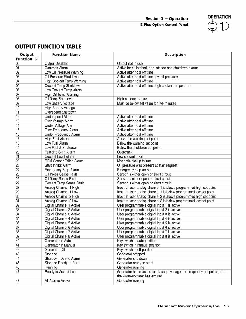
Output Function Name DescriptionFunction ID00 Output Disabled Output not in use01 Common Alarm Active for all latched, non-latched and shutdown alarms02 Low Oil Pressure Warning Active after hold off time03 Oil Pressure Shutdown Active after hold off time, low oil pressure04 High Coolant Temp Warning Active after hold off time05 Coolant Temp Shutdown Active after hold off time, high coolant temperature06 Low Coolant Temp Alarm07 High Oil Temp Warning08 Oil Temp Shutdown High oil temperature09 Low Battery Voltage Must be below set value for five minutes10 High Battery Voltage11 Overspeed Shutdown12 Underspeed Alarm Active after hold off time13 Over Voltage Alarm Active after hold off time14 Under Voltage Alarm Active after hold off time15 Over Frequency Alarm Active after hold off time16 Under Frequency Alarm Active after hold off time17 High Fuel Alarm Above the warning set point18 Low Fuel Alarm Below the warning set point19 Low Fuel & Shutdown Below the shutdown set point20 Failed to Start Alarm Overcrank21 Coolant Level Alarm Low coolant level22 RPM Sensor Failed Alarm Magnetic pickup failure23 Start Inhibit Alarm Oil pressure was present at start request24 Emergency Stop Alarm Emergency stop active25 Oil Press Sense Fault Sensor is either open or short circuit26 Oil Temp Sense Fault Sensor is either open or short circuit27 Coolant Temp Sense Fault Sensor is either open or short circuit28 Analog Channel 1 High Input at user analog channel 1 is above programmed high set point29 Analog Channel 1 Low Input at user analog channel 1 is below programmed low set point30 Analog Channel 2 High Input at user analog channel 2 is above programmed high set point31 Analog Channel 2 Low Input at user analog channel 2 is below programmed low set point32 Digital Channel 1 Active User programmable digital input 1 is active33 Digital Channel 2 Active User programmable digital input 2 is active34 Digital Channel 3 Active User programmable digital input 3 is active35 Digital Channel 4 Active User programmable digital input 4 is active36 Digital Channel 5 Active User programmable digital input 5 is active37 Digital Channel 6 Active User programmable digital input 6 is active38 Digital Channel 7 Active User programmable digital input 7 is active39 Digital Channel 8 Active User programmable digital input 8 is active40 Generator in Auto Key switch in auto position41 Generator in Manual Key switch in manual position42 Generator Off Key switch in off position43 Stopped Generator stopped44 Shutdown Due to Alarm Generator shutdown45 Stopped Ready to Run Generator ready to start46 Running Generator running47 Ready to Accept Load Generator has reached load accept voltage and frequency set points, and
the warm-up timer has expired48 All Alarms Active Generator running
OUTPUT FUNCTION TABLE
16 Generac® Power Systems, Inc.
E-PLUS PANEL MASTER CONTROL BOX CONFIGURATION SETTINGS
Section 3 — OperationE-Plus Option Control Panel
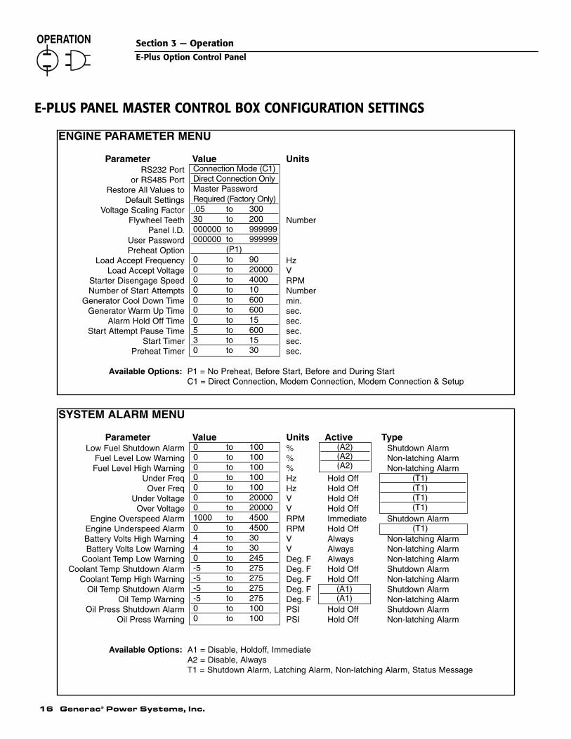
ENGINE PARAMETER MENU
Parameter Value UnitsRS232 Port
or RS485 PortRestore All Values to
Default SettingsVoltage Scaling Factor
Flywheel Teeth NumberPanel I.D.
User PasswordPreheat Option
Load Accept Frequency HzLoad Accept Voltage V
Starter Disengage Speed RPMNumber of Start Attempts Number
Generator Cool Down Time min.Generator Warm Up Time sec.
Alarm Hold Off Time sec.Start Attempt Pause Time sec.
Start Timer sec.Preheat Timer sec.
Available Options: P1 = No Preheat, Before Start, Before and During StartC1 = Direct Connection, Modem Connection, Modem Connection & Setup
Connection Mode (C1)Direct Connection OnlyMaster PasswordRequired (Factory Only).05 to 30030 to 200000000 to 999999000000 to 999999
(P1)0 to 900 to 200000 to 40000 to 100 to 6000 to 6000 to 155 to 6003 to 150 to 30
SYSTEM ALARM MENU
Parameter Value Units Active TypeLow Fuel Shutdown Alarm % Shutdown Alarm
Fuel Level Low Warning % Non-latching AlarmFuel Level High Warning % Non-latching Alarm
Under Freq Hz Hold OffOver Freq Hz Hold Off
Under Voltage V Hold OffOver Voltage V Hold Off
Engine Overspeed Alarm RPM Immediate Shutdown AlarmEngine Underspeed Alarm RPM Hold OffBattery Volts High Warning V Always Non-latching AlarmBattery Volts Low Warning V Always Non-latching Alarm
Coolant Temp Low Warning Deg. F Always Non-latching AlarmCoolant Temp Shutdown Alarm Deg. F Hold Off Shutdown Alarm
Coolant Temp High Warning Deg. F Hold Off Non-latching AlarmOil Temp Shutdown Alarm Deg. F Shutdown Alarm
Oil Temp Warning Deg. F Non-latching AlarmOil Press Shutdown Alarm PSI Hold Off Shutdown Alarm
Oil Press Warning PSI Hold Off Non-latching Alarm
Available Options: A1 = Disable, Holdoff, ImmediateA2 = Disable, AlwaysT1 = Shutdown Alarm, Latching Alarm, Non-latching Alarm, Status Message
0 to 1000 to 1000 to 1000 to 1000 to 1000 to 200000 to 200001000 to 45000 to 45004 to 304 to 300 to 245-5 to 275-5 to 275-5 to 275-5 to 2750 to 1000 to 100
(A2)(A2)(A2)
(T1)(T1)(T1)(T1)
(A1)(A1)
(T1)
Generac® Power Systems, Inc. 17
Section 3 — OperationE-Plus Option Control Panel
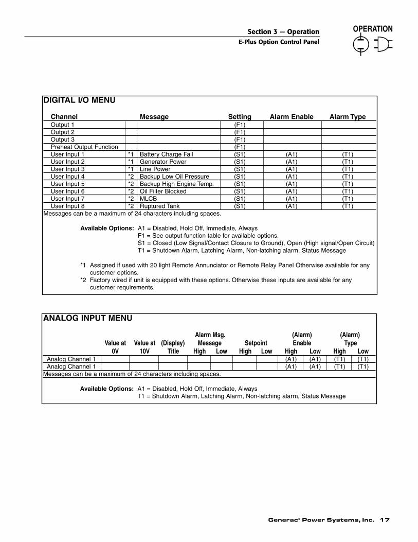
DIGITAL I/O MENU
Channel Message Setting Alarm Enable Alarm TypeOutput 1 (F1)Output 2 (F1)Output 3 (F1)Preheat Output Function (F1)User Input 1 *1 Battery Charge Fail (S1) (A1) (T1)User Input 2 *1 Generator Power (S1) (A1) (T1)User Input 3 *1 Line Power (S1) (A1) (T1)User Input 4 *2 Backup Low Oil Pressure (S1) (A1) (T1)User Input 5 *2 Backup High Engine Temp. (S1) (A1) (T1)User Input 6 *2 Oil Filter Blocked (S1) (A1) (T1)User Input 7 *2 MLCB (S1) (A1) (T1)User Input 8 *2 Ruptured Tank (S1) (A1) (T1)
Messages can be a maximum of 24 characters including spaces.
Available Options: A1 = Disabled, Hold Off, Immediate, AlwaysF1 = See output function table for available options.S1 = Closed (Low Signal/Contact Closure to Ground), Open (High signal/Open Circuit)T1 = Shutdown Alarm, Latching Alarm, Non-latching alarm, Status Message
*1 Assigned if used with 20 light Remote Annunciator or Remote Relay Panel Otherwise available for anycustomer options.
*2 Factory wired if unit is equipped with these options. Otherwise these inputs are available for any customer requirements.
ANALOG INPUT MENU
Alarm Msg. (Alarm) (Alarm)Value at Value at (Display) Message Setpoint Enable Type
0V 10V Title High Low High Low High Low High LowAnalog Channel 1 (A1) (A1) (T1) (T1)Analog Channel 1 (A1) (A1) (T1) (T1)
Messages can be a maximum of 24 characters including spaces.
Available Options: A1 = Disabled, Hold Off, Immediate, AlwaysT1 = Shutdown Alarm, Latching Alarm, Non-latching alarm, Status Message
18 Generac® Power Systems, Inc.
Section 3 — OperationE-Plus Option Control Panel
E-P
AN
EL
DIS
PL
AY
MA
P
R
AL
AR
M S
TA
TU
SA
LA
RM
LO
GIN
ST
RU
ME
NT
AT
ION
PA
RA
ME
TE
R E
NT
RY
SO
FT
WA
RE
VE
RS
ION
GE
NE
RA
TO
R C
OM
MA
ND
run
No a
ctive m
essages *
Lo
gg
ed A
larm
Nu
mb
er
1G
enera
tor
Voltage
XX
X V
olts
Para
mete
r entr
y
Pre
ss E
nte
r to
Continue
Genera
c d
igital panel
Genera
tor
sw
itch o
ff
Softw
are
vers
ion X
.XX
Genera
tor
sw
itch o
ff
Or
* th
is is t
rue
as lo
ng
as
Or
or
Or
or
Or
Ente
rO
rE
nte
r *
Or
Turn
key t
o a
uto
mode:
Or
there
are
no m
essages
Ge
ne
rato
r in
au
to m
od
e
Thru
Hours
Run
* D
isp
lay t
est,
sto
p c
om
ma
nd
Logged A
larm
Num
ber
50
XX
XX
X.X
Hrs
all
pix
els
bla
ck,
all
4 L
ED
sT
urn
key t
o m
anual m
ode:
or
will
be o
nA
tte
mp
tin
g t
o s
tart
Passw
ord
Att
em
pt
nu
mb
er
X
An
alo
g I
nput
2X
XX
XX
X
X.X
Ente
r
or
Analo
g I
nput
1E
ngin
e P
ara
mete
r M
enu
Or
Syste
m A
larm
Me
nu
Or
Dig
ita
l I/
O M
en
uO
rA
na
log
In
pu
t m
en
u
X.X or
or
or
or
or
Fuel Level
Low
Fuel S
hutd
ow
n E
nable
Input
Ch 8
Ala
rm T
ype
Analo
g C
h 2
Low
Type
XR
S485 P
ort
or
Dire
ct
Co
nn
ectio
n o
nly
or
or
or
or
Battery
Voltage
RS
232 P
ort
Low
Fuel S
hutd
ow
n S
etp
tIn
put
Ch
8 A
larm
enable
Analo
g C
h 2
Hig
h T
ype
XX
.X V
olts
Direct
conection
XX
%
or
or
or
or
or
RS
232 P
ort
Oil
Pre
ssu
reM
odem
connection
Fuel Level Low
Enable
Input
Channel 8 S
ettin
gA
nalo
g C
h 2
Low
Enable
XX
X p
.s.I
or
or
RS
232 P
ort
or
or
or
Modem
connection &
Setu
p
Oil
Te
mp
era
ture
or
Fuel Level Low
Setp
oin
tIn
put
Channel 8 M
essage
Analo
g C
h 2
Hig
h E
nable
XX
X d
eg F
XX
%
or
Resto
re a
ll valu
es
or
or
or
to d
efa
ult s
ettin
gs
Coola
nt
Tem
pera
ture
or
Fuel Level H
igh E
nable
Input
Ch 7
Ala
rm T
ype
Analo
g C
h 2
low
Setp
oin
t
XX
X d
eg.
FX
.X
or
Vo
lta
ge
Sca
ling
Fa
cto
ro
ro
ro
rX
XX
.XX
Engin
e S
peed
or
Fuel Level H
igh S
etp
oin
tIn
put
Ch 7
Ala
rm E
nable
Analo
g C
h 2
Hig
h S
etp
oin
t
XX
XX
Rpm
XX
%X
.X
or
Fly
wheel T
eeth
or
or
or
XX
X
Genera
tor
Fre
quency
or
Under
Fre
q A
larm
Type
Input
Channel 7 S
ettin
gA
nalo
g 2
Low
Ala
rm M
sg
XX
.XH
z
Panel I.D
.o
ro
ro
rX
XX
XX
X
or
Under
Fre
q S
etp
oin
tIn
put
Channel 7 M
essage
Analo
g C
h 2
Hig
h A
larm
Msg
XX
.X H
z
User
Passw
ord
or
or
or
XX
XX
XX
or
Ove
r F
req
Ala
rm T
yp
eIn
pu
t C
h 6
Ala
rm T
yp
eA
na
log
Ch
an
ne
l 2
Title
Pre
heat
Option
or
or
or
or
Over
Fre
q S
etp
oin
tIn
put
Ch 6
Ala
rm e
nable
Analo
g C
h 2
Valu
e a
t 10V
XX
.X H
zX
.X
Load A
ccept
Fre
quency
or
or
or
XX
.X H
z
or
Under
Voltage A
larm
Type
Input
Channel 6 S
ettin
gA
nalo
g C
h 2
valu
e a
t 0V
X.X
Load A
ccept
Voltage
or
or
or
XX
X V
olts
or
Under
Voltage S
etp
oin
tIn
put
Channel 6 M
essage
Analo
g C
h 1
Low
Type
XX
X V
olts
Sta
rter
Dis
engage S
peed
or
or
or
XX
X R
PM
or
Over
Voltage A
larm
Type
Input
Ch 5
Ala
rm T
ype
Analo
g C
h 1
Hig
h T
ype
Nu
mb
er
of
Sta
rt A
tte
mp
tso
ro
ro
rX
E-PLUS PANEL DISPLAY MAP
E-PL
US
PAN
EL D
ISPL
AY M
AP
Generac® Power Systems, Inc. 19
Section 3 — OperationE-Plus Option Control Panel
or
or
or
X or
Over
Voltage S
etp
oin
tIn
put
Ch 5
Ala
rm E
nable
Analo
g C
h 1
Low
Enable
XX
X V
olts
Ge
ne
rato
r C
oo
l D
ow
n T
ime
or
or
or
X M
in
or
Overs
peed S
hutd
ow
n S
etp
tIn
put
Channel 5 S
ettin
gA
nalo
g C
h 1
Hig
h E
nable
XX
XX
Rpm
Ge
n.
Wa
rm U
p T
ime
or
or
or
X S
ec
or
Unders
peed A
larm
Type
Input
Channel 5 M
essage
Analo
g C
h 1
low
Setp
oin
t
X.X
Ala
rm H
old
Off
Tim
eo
ro
ro
rX
X S
ec
or
Unders
peed A
larm
Setp
tIn
put
Ch 4
Ala
rm T
ype
Analo
g C
h 1
Hig
h S
etp
oin
t
XX
XX
Rpm
X.X
Sta
rt A
tte
mp
t P
au
se
Tim
eo
ro
ro
rX
X S
ec
or
Ba
tte
ry V
olts H
igh
Se
tpt
Inp
ut
Ch
4 A
larm
En
ab
leA
na
log
1 L
ow
Ala
rm M
sg
XX
.X V
Sta
rt T
ime
ro
ro
ro
rX
X S
ec
or
Battery
Volts L
ow
Setp
tIn
put
Channel 4 S
ettin
gA
nalo
g C
h 1
Hig
h A
larm
Msg
XX
.X V
Pre
heat
Tim
er
or
or
or
XX
Sec
Coola
nt
Tem
p low
Setp
tIn
put
Channel 4 M
essa
ge
An
alo
g C
ha
nn
el 1
Title
XX
X D
eg F
or
or
or
Coola
nt
Tem
p S
hutd
n S
etp
t.In
put
Ch 3
Ala
rm T
ype
Analo
g C
h 1
Valu
e a
t 10V
XX
X D
eg F
X.X
or
or
or
Coola
nt
Tem
p H
igh S
etp
t In
pu
t C
h 3
Ala
rm E
na
ble
Analo
g C
h 1
valu
e a
t 0V
XX
X D
eg F
X.X
or
or
Oil
Tem
p S
hutd
ow
n E
nable
Input
Channel 3 S
ettin
g
or
or
Oil
Tem
p.
Shutd
ow
n S
etp
tIn
put
Channel 3 M
essage
XX
Deg F
or
or
Oil
Te
mp
Wa
rn E
na
ble
Input
Ch 2
Ala
rm T
ype
or
or
Oil
Te
mp
. W
arn
Se
tpt
Inp
ut
Ch
2 A
larm
En
ab
le
XX
Deg F
or
or
Oil
Pre
ss S
hutd
ow
n S
etp
tIn
put
Channel 2 S
ettin
g
XX
Psi
or
or
Oil
Pre
ss W
arn
Setp
tIn
put
Channel 2 M
essage
XX
Psi
or
Input
Ch 1
Ala
rm T
ype
or
Inp
ut
Ch
1 A
larm
En
ab
le
or
Input
Channel 1 S
ettin
g
or
Input
Channel 1 M
essage
or
Pre
heat
Outp
ut
Function
or
Ou
tpu
t 3
Fu
nctio
n
or
Ou
tpu
t 2
Fu
nctio
n
or
Ou
tpu
t 1
Fu
nctio
n

20 Generac® Power Systems, Inc.
Section 4 — Troubleshooting
E-Plus Option Control Panel
Dip Switch Setting1 Up2 Down3 Down4 Down5 Up6 Up7 Up8 Down
TABLE A
“E” Panel Pin Modem Pin1 82 33 24 205 7
TABLE B

Generac® Power Systems, Inc. 21
LEG
EN
D
TB
4
TB
2T
B3
BC
2B
C1
- P
RO
G. O
UT
PU
TS
TE
RM
INA
L B
LOC
K-
PR
OG
. IN
PU
T T
ER
MIN
AL
BLO
CK
- C
OM
MU
NIC
AT
ION
S T
ER
MIN
AL
BLO
CK
- B
ULK
HE
AD
CO
NN
EC
TO
R 2
(12
PIN
)-
BU
LKH
EA
D C
ON
NE
CT
OR
1 (
31 P
IN)
TB
4
3
BC
2
BC
1
TB
2
121197 85 64
TB
3
21
3 4 521
A8
PR
OG
RA
M
INP
UT
7P
RO
GR
AM
INP
UT
6P
RO
GR
AM
A6
INP
UT
5P
RO
GR
AM
A5
PR
OG
RA
M
A4
INP
UT
3P
RO
GR
AM
INP
UT
2P
RO
GR
AM
A2
INP
UT
1P
RO
GR
AM
A1
PR
OG
RA
M
A0 A0
GN
D
485+
485-
SC
RE
EN
0V
+12/
24V
A0 A1
A2
A3
BLA
CK
CLE
AR
BA
RE
BLA
CK
RE
D
J118
RE
MO
TE
AN
NU
NC
IAT
OR
PR
INT
ED
CIR
CU
IT B
OA
RD
BLACK
CLEAR
BLACK
RED
INS
IDE
RE
MO
TE
AN
NU
NC
IAT
OR
PA
NE
L
CU
T O
FF
SH
IELD
DR
AIN
(B
AR
EW
IRE
) A
T E
ND
OF
INS
ULA
TIO
N.
A0
BA
TTE
RY
CH
AR
GE
RFA
IL S
IGN
AL
TO G
EN
ER
ATO
R P
OW
ER
TRA
NS
FER
SW
ITC
H
TO U
TILI
TY P
OW
ER
TRA
NS
FER
SW
ITC
H
NC
NO
CO
MA
UT
OM
AT
ICT
RA
NS
FE
RS
WIT
CH
NO
NC
CO
M
CONTACTSAUXILIARY
A0
A3
A2
SW
ITC
H C
AB
INE
TIN
SID
E A
UT
OM
AT
IC T
RA
NS
FE
R(C
US
TO
ME
R O
PT
ION
)
(CU
ST
OM
ER
OP
TIO
N)
120
VA
C R
ELA
Y W
IRE
D IN
PA
RA
LLE
LW
ITH
BA
TT
ER
Y C
HA
RG
ER
FA
IL
BA
TT
ER
Y C
HA
RG
ER
.
NC
NO
CO
M
A1
A0
TO
RE
LAY
NO
RM
ALL
Y C
LOS
ED
CO
NT
AC
TS
(CU
ST
OM
ER
SU
PP
LIE
D)
RE
MO
TE
AN
NU
NC
IAT
OR
AU
TO
MA
TIC
TR
AN
SF
ER
SW
ITC
H
WIR
ING
CA
N B
E R
UN
TH
RO
UG
H A
NY
OF
TH
E K
NO
CK
-OU
TS
OR
TH
EC
OM
MU
NIC
AT
ION
S P
OR
T W
ITH
TH
E S
UP
PLI
ED
GR
OM
ME
T.
"E-P
LUS
" C
ON
TR
OL
PA
NE
L
INS
IDE
OF
BA
CK
PA
NE
L
SHIELDED CABLE
INS
TA
LLA
TIO
N N
OT
ES
:1.
) A
LL S
IGN
AL
AN
D C
ON
TR
OL
WIR
ING
MU
ST
BE
RU
N IN
SE
PA
RA
TE
CO
ND
UIT
FR
OM
AC
FE
ED
S.
2.)
MIN
IMU
M R
EQ
UIR
ED
WIR
E G
AU
GE
FO
R L
EN
GT
H O
F R
UN
:
MA
X. W
IRE
LE
NG
TH
FE
ET
(M
ET
ER
S)
250
(76)
1200
(36
5)
RE
CO
MM
EN
DE
D W
IRE
SIZ
E (
AW
G)
24 18
FO
R S
HIE
LDE
D C
AB
LE
FO
R C
ON
TR
OL
WIR
E
RE
CO
MM
EN
DE
D W
IRE
FE
ET
(M
ET
ER
S)
MA
X. W
IRE
LE
NG
TH
730
(223
)
460
(140
)
SIZ
E (
AW
G)
18 16
1850
(56
5)
1160
(35
4)
1214
Section 5 — Interconnection DiagramCommunication Interconnection Diagram — Drawing No. 0E2283
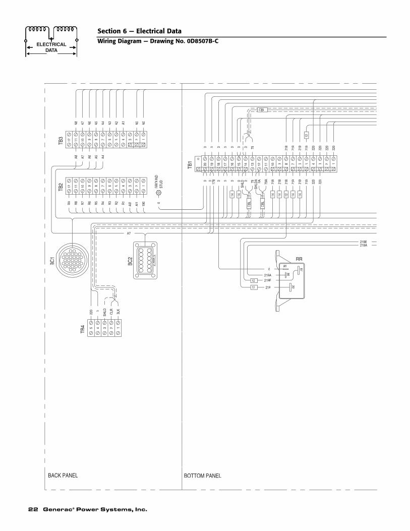
22 Generac® Power Systems, Inc.
Section 6 — Electrical DataWiring Diagram — Drawing No. 0D8507B-C
7979
13
BACK PANEL BOTTOM PANEL
R3
6
5
TB4 4 3
220
SHLD0
BC1
R4
TB2
R9
12
R7
R8
R6
10 9
R5
8
12
BLK
CLR
BC2
190
AI2
A7
1
R2 R1
5 4
AI1
2 STU
DG
RO
UN
D0
CBL
TB1
0 020
SHLD
14 14
016
00
1718
014
A36
TB3
12
A7A8 A6
10 9
A5 A4
8
A7A8 A6 A5 A4 A015 4 2
A2 A1 A0
0 0 000 0 0
85
218
219B219A
12
12
0
8630
87
RR
219A219B
CBL
1221
8
SHLD
A 0A 218
218
1414
12 10 9
219
219
219
220
220
1414
6 5 3 2 1
218
12
219
219
219
220
220
CBL
220
220
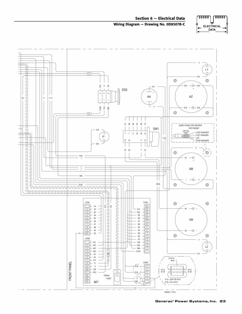
Generac® Power Systems, Inc. 23
Section 6 — Electrical DataWiring Diagram — Drawing No. 0D8507B-C
SHEET 1 OF 2
CON3CON1
FRO
NT
PAN
EL
131211
14
10
MC1PORT
SERIAL
183R15
5738
079
6 68
CON2
10
CBL
1 AI1575
523AI23
45 69
2
9 A0A0
4 A4
78
A7A8
6A5A6
2 A2A3
1 A1 R15
183
L2
#?-A = #220 OR #S16#?-B = #0 or #S15
FERRITEBEAD
5S15
2200
3
12
4
S16
CON4
6
#?-B#?-A #?-A
#?-B
219
190 4
219A56A 2
1
R4
R2 6
8
R9 13R8R7R6R5 9
1011
515220
1516
VM
64
0
-
65 +
6558
715
22 2
056
219A
56A
00
0R15
64
0 0
220
F1
218
193
57
56A
1
R15
219B
12
1 1
56219 0
12
ESS
LOCK WASHER
STAR WASHER
0
64 65
0 67
0
-
0
AM
67
+
122
11 18
59 S3
16 14
S2 S1
5150
SW1
AH
-
0
GROUNDINGDIRECTIONS FOR PROPER
FLAT WASHERLUG
HZ
S16 S16
-
515
+
S15
+
S15
219
L1
0
0
0

6 HZ-18 USEDS16SW1-3SW1-7SW1-11
TB1-19CON2-10
TB1-19
7 8 9 1210 11
11 17812 183
78
109 59
0
5758
1818
1818
1818
USEDUSED
USEDUSED
USEDUSED
SW1-18SW1-16
TO
HZ+TB2-10
SW1-14
WIRE TERMINATION
TOTB1-17
CON2-2TB2-8TB1-3
TB1-5TB1-7
TB1-12TB1-6
TB2-9TB1-17
TB2-7CON2-5
TB2-11
TB1-14
TB1-16ESS-12
TB1-11TB1-15
CON2-7TB1-12
TB1-13
CON2-4CON2-6
TB1-14
TB1-9TB1-10
WIRE TERMINATION
ARE NEEDED.
RESERVED PINS WILL BE POPULATED
AND SMOKE LIMITING RELAY KITSONLY WHEN THE INTERNAL GOVERNOR
IN THAT ORDER.& SHLDA GO TO PINS 22, 10, & 23SHIELDED CABLE 2 WITH WIRES 79A, 0A,
IN THAT ORDER.& SHLD GO TO PINS 16, 17, & 28SHIELDED CABLE 1 WITH WIRES 79, 0,
25
BC2
DEUTSCH
6 5 4 13 2
WIRE
3
54
2
A7S15
S2S3
PIN1 S1
1818
1818
GAUGE18
SHLD
2183031 218
29282726
169
52368
1414
14-
1818
207916
SHLDA79A
24232221
573
020191817
168
056
0
18-
2014
14
1418
20
A811
15141312
A469A60
10987
2190A
219219
18
18181818
1420
1814
WIRE
2
6543
220
575A5
353
PIN1 0
18
1818
14
GAUGE18
OPEN
USEDUSED
USEDUSED
STATUSUSED
RESERVEDUSEDUSED
USEDUSEDUSED
USED
RESERVED
USEDUSED
USEDUSEDUSEDUSED
USED
USED
USEDUSEDUSEDUSED
USEDUSED
USEDUSED
RESERVEDOPEN
USED
USEDUSED
STATUSUSED
PIN
14
1
5
2
BC1
8
2726
15
18
16
176
7
3031
19
28
29
25
1324
114
12
310
20
921
23
22
24 Generac® Power Systems, Inc.
Section 6 — Electrical DataWiring Diagram — Drawing No. 0D8507B-C

Generac® Power Systems, Inc. 25
- BULKHEAD CONNECTOR 1 (31 PIN)- BULKHEAD CONNECTOR 2 (12 PIN)
ALL WIRING 18 AWG UNLESS NOTED
SHIELDED CABLE
WIRE GAUGE NOTE
- PLUG 3.5 10 POS
- FREQUENCY METER
- PLUG 3.5 6 POS- PLUG 3.5 16 POS- PLUG 3.5 14 POS
- E-PANEL CONTROLLER ASSEMBLY
- EMERGENCY STOP SWITCH
- TERMINAL BLOCK 4(5 POS)- TERMINAL BLOCK 3(12 POS)- TERMINAL BLOCK 2(12 POS)- TERMINAL BLOCK 1(20 POS)- VOLT/AMMETER SELECTOR SWITCH
TO
TB4-2TB4-1
WIRE TERMINATION
CABLE JACKET AT THIS END.CUT SHIELD DRAIN WIRE EVEN WITH 7
89
SERIAL PORT
321
6 7
54
8 9
WIRE
2 BLK3
54
6
CLR
PIN1
2020
GAUGE
OPEN
OPENOPEN
USED
OPENOPEN
USEDOPEN
STATUSOPEN
L1/L2 - PANEL LAMP
- VOLTMETER
- RUN RELAY
TB2
VMTB4TB3
SW1TB1
MC1RR
AM - AMMETER
- 15 AMP FUSE
CON3
HZF1ESSCON4
CON1CON2
BC2BC1
12
CBL
- ALARM HORNAH
LEGEND
NOTES:
Section 6 — Electrical DataWiring Diagram — Drawing No. 0D8507B-C
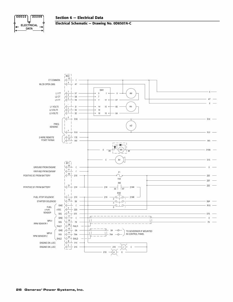
26 Generac® Power Systems, Inc.
Section 6 — Electrical DataElectrical Schematic — Drawing No. 0D8507A-C
SHLD
SHLD
SENSING
1
RPM SENSOR 2
RPM SENSOR 1
ENGINE ON (+DC)
ENGINE ON (+DC) 2199
219
+VDC
SIG.
GND
SIG.
SHLD
SIG.
SHLD
GND
GND
MPU2
FUELLEVEL
SENDER
MPU1
10
22
2379A
0A
17
16
4
575
79
0
220
0
2-WIRE REMOTE
GROUND FROM ENGINE
GROUND FROM ENGINE
POSITIVE DC FROM BATTERY
POSITIVE DC FROM BATTERY
STARTER SOLENOID
FUEL STOP SOLENOID
20
31
19
7219
56
218
21
30218
0
0
START SIGNAL
BC1
11
12
5
178
183
S15
MLCB OPEN (589)
L2 CT
L3 CT
L3 VOLTS
L2 VOLTS
L1 VOLTS
FREQ.
L1 CT
2
6
3
S16
S2
S3
9
1
7
8
59
S1
58
57
CT COMMON
BC210
40
A7
TO GOVERNOR IF MOUNTED
219 L2
219
79A
0A
2
0
L1 0
IN CONTROL PANEL
1
218
219
2
2
30
0
0 85
1
1
ESS
87
219B
219B
15A
RR
F1
AH
RR 86
575
79
0
R15
220
56A
220
220
0
515
219A
183
S15
67
64
65
0
16
18 19
11
14
12
15
SW1
7
3 2
HZ
VM
AM
S16
0
A7
0
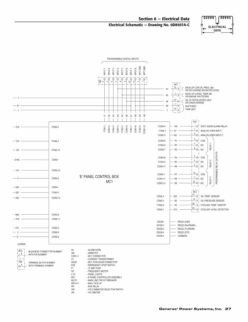
Generac® Power Systems, Inc. 27
Section 6 — Electrical DataElectrical Schematic — Drawing No. 0D8507A-C
ESS - EMERGENCY STOP SWITCH
- MAIN LINE CIRCUIT BREAKER
- VOLT/AMMETER SELECTOR SWITCH
- E-PANEL CONTROLLER ASSEMBLY
- 15 AMP FUSE
- PANEL LIGHTS- FREQUENCY METER
- MAG. PICK-UP- RUN RELAY
- VOLTMETER
RRSW1VM
MLCBMPU1/2
MC1L1/2
F1HZ
CON2-3
CON2-1
CON3-5
CON3-6
CON3-7
CON3-4
CON3-8
CON3-9
CON3-11
CON3-10
CON3-13
CON2-4
CON2-5
CON3-12
CON2-7
DSUB-1
DSUB-3
DSUB-2
DSUB-5
DSUB-4
CON2-6
- MC1 9 PIN DSUB CONNECTOR
- AMMETER
- CURRENT TRANSFORMER
BULKHEAD CONNECTOR NUMBER
TERMINAL BLOCK NUMBERWITH TERMINAL NUMBER
- ALARM HORN
- MC1 CONNECTORWITH PIN NUMBER
CON1-4
DSUBCT
AMAH
#TB#
BC##
R15
575
79
LEGEND
0
CON2-2
CON2-11
CON2-8
CON2-9
220
220
220
56A
0
S15
183
515
219A
CON4-1
CON3-14
CON3-3
CON4-2
CON3-2
CON4-4
CON2-10
CON3-1
CON3-15
'E' PANEL CONTROL BOXMC1
S16
0
A7
0
CON4-6
PROGRAMABLE DIGITAL INPUTS
A4A3A1 A2C
ON
1-2
CO
N1-
1
CO
N1-
3
CO
N1-
4
INPU
T 3
INPU
T 4
INPU
T 1
INPU
T 2
4TB3 5 6 7
A0C
ON
1-9
A8A7A6A5C
ON
1-5
CO
N1-
6
CO
N1-
8
CO
N1-
7
A0C
ON
1-10
2IN
PT G
ND
INPU
T 8
INPU
T 5
INPU
T 6
INPU
T 7
108 9 11
INPT
GN
D1
ANALOG USER INPUT 2AI2
RS232 (Rx)/RS485+
RS232 (Tx)/RS485-
RS232 (DSR)
COMMON
RS232 (DTR)
11
573
69
68
523
R9
R8
24
26
14
27BC1
12
R6
R7
R4
R5
R2
R3
R1
7
10
9
8
6
5
4
REL
AY 3
PRO
GR
AMAB
LE R
ELAY
OU
TPU
TS
OIL PRESSURE SENSOR
OIL TEMP. SENSOR
COOLANT LEVEL DETECTOR
COOLANT TEMP. SENSOR
NC
NO
REL
AY 2
NC
COM
COM
NO
REL
AY 1
NO
NC
COM
BACK-UP HI ENG. TEMP (85)OR ENGINE SHUTDOWN
OR OR CHARGE AIR WATER LEVELBACK-UP LOW OIL PRES. (86)
TANK (567)
OR CHECK ENGINEOIL FILTER BLOCKED (354)
5
AI1
190
0
A8
A5
A611
12
13
1
2
3
TB2
RUPTURED
A4
BC115
ANALOG USER INPUT 1
SHUT DOWN ALARM RELAY

RP
M S
EN
SO
R 2
EN
GIN
E O
N (
+D
C)
GR
OU
ND
FR
OM
EN
GIN
E
SH
LD
GN
D
SIG
.M
PU
212
0A
SH
LD
79A
167
0
219
GO
V-
GO
VE
RN
OR
LEG
EN
D
TB
# #
BC
# #B
ULK
HE
AD
CO
NN
EC
TO
R N
UM
BE
R
WIT
H T
ER
MIN
AL
NU
MB
ER
TE
RM
INA
L B
LOC
K N
UM
BE
R
WIT
H P
IN N
UM
BE
R
TB
1
0B
AT
TE
RY
-
MP
U
0A79A
BA
TT
ER
Y+
219
GO
VE
RN
OR
EN
GIN
E
OR
PIC
K-U
PG
OV
- B
ULK
HE
AD
CO
NN
EC
TO
R 1
(31
PIN
)-
BU
LKH
EA
D C
ON
NE
CT
OR
2 (
12 P
IN)
79A
13
- T
ER
MIN
AL
BLO
CK
4(5
PO
S)
- T
ER
MIN
AL
BLO
CK
3(1
2 P
OS
)-
TE
RM
INA
L B
LOC
K 2
(12
PO
S)
- T
ER
MIN
AL
BLO
CK
1(2
0 P
OS
)
BA
CK
PA
NE
L
BO
TT
OM
PA
NE
L
TB
2
TB
4T
B3
TB
1B
C2
BC
1
AR
EN
EE
DE
D.
RE
SE
RV
ED
PIN
S W
ILL
BE
PO
PU
LAT
ED
AN
D S
MO
KE
LIM
ITIN
G R
ELA
Y K
ITS
ON
LY W
HE
N T
HE
INT
ER
NA
L G
OV
ER
NO
R
2916
914
1816
814
RE
SE
RV
ED
TB4
BC1
RE
SE
RV
ED
TB2
BC2
TB1
20
19
16
17
18
14
TB3
0
0A
PIN
1427
261516
28291
65
72
251324
412
3
2322
3031 19
820 9
21
8
12
11
10
9
6
4
5
3
2
1
219
CB
L
168
169
EN
GIN
EG
OV
ER
NO
RG
OV
ACTUATOR
0
219
BATTERY -
BATTERY +
MPUOR
PICK-UP
0A
79ACBL
SID
E O
F P
AN
EL
021
916
8
169
AC
TU
AT
OR
168
169
29A
CT
UA
TO
R
BC
1 18
169
168
AC
TU
AT
OR
SC
HE
MA
TIC
GO
VG
OV
MP
U2
- M
AG
. PIC
K-U
P
45
21
1011
AB
EF
CD
BA
RB
ER
CO
LMA
N
GO
VE
RN
OR
S A
ME
RIC
A C
OR
P. (
GA
C)
OR
GH
AN
A C
ON
TR
OL
ALL
WIR
ING
14
AW
G U
NLE
SS
NO
TE
D
SH
IELD
ED
CA
BLE
WIR
E G
AU
GE
NO
TE
CB
L
LEG
EN
D
TO
WIR
E T
ER
MIN
AT
ION
WIR
EP
ING
AU
GE
NO
TE
S:
ST
AT
US
BC
1W
IRIN
G D
IAG
RA
M
169
168
WIR
E T
WIS
TE
D P
AIR
BLK
RED
RED
BLK
RE
D
BLK
RED
BLK
28 Generac® Power Systems, Inc.
Section 6 — Electrical DataWiring Diagram — Engine Governor — Drawing No. 0E0062A
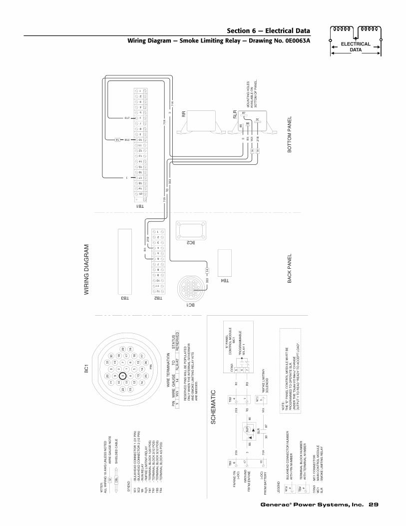
Generac® Power Systems, Inc. 29
64
LEG
EN
D
#
BC
# #B
ULK
HE
AD
CO
NN
EC
TO
R N
UM
BE
R
WIT
H T
ER
MIN
AL
NU
MB
ER
TE
RM
INA
L B
LOC
K N
UM
BE
R
WIT
H P
IN N
UM
BE
R
TB
2
R3R1
- B
ULK
HE
AD
CO
NN
EC
TO
R 1
(31
PIN
)-
BU
LKH
EA
D C
ON
NE
CT
OR
2 (
12 P
IN)
13
ALL
WIR
ING
18
AW
G U
NLE
SS
NO
TE
D
SH
IELD
ED
CA
BLE
WIR
E G
AU
GE
NO
TE
- T
ER
MIN
AL
BLO
CK
4(5
PO
S)
- T
ER
MIN
AL
BLO
CK
3(1
2 P
OS
)-
TE
RM
INA
L B
LOC
K 2
(12
PO
S)
- T
ER
MIN
AL
BLO
CK
1(2
0 P
OS
)
BA
CK
PA
NE
LB
OT
TO
M P
AN
EL
TB
2
TB
4T
B3
TB
1
BC
2B
C1
12 CB
L
LEG
EN
D
TO
WIR
E T
ER
MIN
AT
ION
AR
EN
EE
DE
D.
RE
SE
RV
ED
PIN
S W
ILL
BE
PO
PU
LAT
ED
AN
D S
MO
KE
LIM
ITIN
G R
ELA
Y K
ITS
ON
LY W
HE
N T
HE
INT
ER
NA
L G
OV
ER
NO
R
WIR
EP
ING
AU
GE
TB4
BC1
TB2
BC2
NO
TE
S:
TB1
20
19
16
17
14
ST
AT
US
TB3
0
PIN
BC
1
8
11
10
9
7
6
4
5
3
2
1
14 218
353
14
218
035
3
SM
OK
E L
IMIT
ING
SC
HE
MA
TIC
WIR
ING
DIA
GR
AM
335
314
RE
SE
RV
ED
85
1421
8
1435
3R
30
87
3086
SLR219
11
12
9
10
8
5
6
7
2
4
3
1
TH
E "
E"
PA
NE
L C
ON
TR
OL
MO
DU
LE M
US
T B
EP
RO
GR
AM
ME
D T
O O
PE
RA
TE
SLR
.
NO
TE
:
'E'P
AN
EL
CO
NT
RO
L M
OD
ULE
MC
1
RE
LAY
1P
RO
GR
AM
MA
BLE
EN
GIN
E O
N
GR
OU
ND
176T
B1
219
R3
85S
LR86
0
353
3BC
1
218
(+D
C)
10
8730
SO
LEN
OID
219
6 75CO
N3
219
R3
219
R3
219
UN
DE
R T
HE
"D
igita
l I/O
Men
u" C
HA
NG
E
SLR
- S
MO
KE
LIM
ITIN
G R
ELA
Y
RR
- R
UN
RE
LAY
RR
MO
UN
TIN
G H
OLE
SA
VA
ILA
BLE
ON
BO
TT
OM
OF
PA
NE
L.
- M
AIN
CO
NT
RO
L M
OD
ULE
- S
MO
KE
LIM
ITIN
G R
ELA
Y
- M
C1
CO
NN
EC
TO
R
SLR
MC
1C
ON
3
(+D
C)
FR
OM
BA
TT
ER
Y
FR
OM
EN
GIN
E
SLR
-87
15 2627
281617
142513
56
14
24
2312
291830
192
7
831
20
221021
OU
TP
UT
1 T
O R
EA
D "
RE
AD
Y T
O A
CC
EP
T L
OA
D".
Section 6 — Electrical DataWiring Diagram — Smoke Limiting Relay — Drawing No. 0E0063A
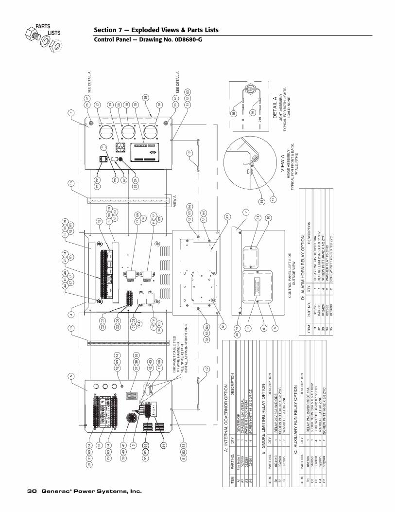
30 Generac® Power Systems, Inc.
68
54VIE
WA
CO
NT
RO
L P
AN
EL
LEF
T S
IDE
C3
C4
C5
C2C1
ITE
M
B2
B3
ITE
M
RE
LAY
PN
L 24
VD
C 3
PD
T 1
0AB
LOC
K T
ER
M 2
0A 5
X 6
X 1
100V
SC
RE
W P
HT
T #
6-32
X 1
/2 Z
YC
WA
SH
ER
FLA
T #
6 Z
INC
SC
RE
W P
HT
T #
6-32
X 3
/8 Z
YC
SC
RE
W P
HT
T #
6-32
X 3
/8 Z
YC
0817
6604
8850
0C24
2802
2985
0C26
99
4 2 21 1
PA
RT
NO
.
PA
RT
NO
.
0C41
10
0229
850C
2699
QT
Y1 2 2
QT
YD
ES
CR
IPT
ION
DE
SC
RIP
TIO
N
D5
D2
D4
ITE
M
D1
BLO
CK
TE
RM
20A
5 X
6 X
110
0V
WA
SH
ER
FLA
T #
6 Z
INC
SC
RE
W P
HT
T #
6-32
X 1
/2 Z
YC
0488
500C
2428
0229
850C
2699
21 2
RE
LAY
PN
L 24
VD
C 3
PD
T 1
0A08
1766
PA
RT
NO
.Q
TY 1
DE
SC
RIP
TIO
N
OU
TS
IDE
VIE
W
A4
A2A1
ITE
M
GO
VE
RN
OR
B:
SM
OK
E L
IMIT
ING
RE
LAY
OP
TIO
N
CH
AS
SIS
, UN
IVE
RS
AL
SC
RE
W H
HT
T #
8-32
X 3
/8 C
Z
0E35
5002
2264
0249
1141 4
See
Not
e 1
PA
RT
NO
.Q
TY 1
DE
SC
RIP
TIO
N
34 5351
52
341
3063
3940
33 6464
2963
3129
63
5452
53D
3D
2
5452
5312
9 861
49
A1
53
38
GR
OM
ME
T C
AB
LE T
IED
TO
WIR
E H
AR
NE
SS
.S
EE
NO
TE
#2
FO
RIN
ST
ALL
AT
ION
INS
TR
UC
TIO
NS
.
5043
11
C26
884237
D5
D4
55C
4 D3
D1
C5
C1
A3
A4
BE
HIN
D C
OV
ER
(IF
SO
EQ
UIP
PE
D)
GO
VE
RN
OR
CO
NT
RO
L
7
1061A2
B3
5253
62
B2
B1
5927
5
C3
C2
134
28
60
4446
45
48
32
62
3635
59
63
36
62
3135
59
63
TY
PIC
AL
FO
R B
OT
H L
IGH
TS
.
TY
PIC
AL
FO
R F
RO
NT
& B
AC
K.
VIE
WA
HIN
GE
AS
SE
MB
LY
SC
ALE
: NO
NE
DE
TA
ILA
LIG
HT
AS
SE
MB
LY
SC
ALE
: NO
NE
58
5226
14
13
12
2467
23
16 51251518
66
219
65
0
SE
E D
ET
AIL
A
53
26
202221
13
17 1925
6
SE
E D
ET
AIL
A
Section 7 — Exploded Views & Parts ListsControl Panel — Drawing No. 0D8680-G
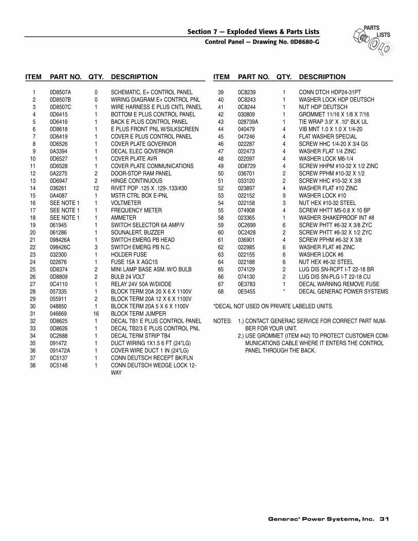
Generac® Power Systems, Inc. 31
ITEM PART NO. QTY. DESCRIPTION
1 0D8507A 0 SCHEMATIC, E+ CONTROL PANEL2 0D8507B 0 WIRING DIAGRAM E+ CONTROL PNL3 0D8507C 1 WIRE HARNESS E PLUS CNTL PANEL4 0D6415 1 BOTTOM E PLUS CONTROL PANEL5 0D6416 1 BACK E PLUS CONTROL PANEL6 0D8618 1 E PLUS FRONT PNL W/SILKSCREEN7 0D6419 1 COVER E PLUS CONTROL PANEL8 0D6526 1 COVER PLATE GOVERNOR9 0A3394 1 DECAL ELEC GOVERNOR
10 0D6527 1 COVER PLATE AVR11 0D6528 1 COVER PLATE COMMUNICATIONS12 0A2275 2 DOOR-STOP RAM PANEL13 0D6947 2 HINGE CONTINUOUS14 036261 12 RIVET POP .125 X .129-.133/#3015 0A4087 1 MSTR CTRL BOX E-PNL16 SEE NOTE 1 1 VOLTMETER17 SEE NOTE 1 1 FREQUENCY METER18 SEE NOTE 1 1 AMMETER19 061945 1 SWITCH SELECTOR 6A AMP/V20 061286 1 SOUNALERT, BUZZER21 098426A 1 SWITCH EMERG PB HEAD22 098426C 3 SWITCH EMERG PB N.C.23 032300 1 HOLDER FUSE24 022676 1 FUSE 15A X AGC1525 0D8374 2 MINI LAMP BASE ASM. W/O BULB26 0D8809 2 BULB 24 VOLT 27 0C4110 1 RELAY 24V 50A W/DIODE28 057335 1 BLOCK TERM 20A 20 X 6 X 1100V29 055911 2 BLOCK TERM 20A 12 X 6 X 1100V30 048850 1 BLOCK TERM 20A 5 X 6 X 1100V31 046669 16 BLOCK TERM JUMPER32 0D8625 1 DECAL TB1 E PLUS CONTROL PANEL33 0D8626 1 DECAL TB2/3 E PLUS CONTROL PNL34 0C2688 1 DECAL TERM STRIP TB435 091472 1 DUCT WIRING 1X1.5 6 FT (24"LG)36 091472A 1 COVER WIRE DUCT 1 IN (24"LG)37 0C5137 1 CONN DEUTSCH RECEPT BK/FLN38 0C5148 1 CONN DEUTSCH WEDGE LOCK 12-
WAY
ITEM PART NO. QTY. DESCRIPTION
39 0C8239 1 CONN DTCH HDP24-31PT40 0C8243 1 WASHER LOCK HDP DEUTSCH41 0C8244 1 NUT HDP DEUTSCH42 030809 1 GROMMET 11/16 X 1/8 X 7/1643 028739A 1 TIE WRAP 3.9" X .10" BLK UL44 040479 4 VIB MNT 1.0 X 1.0 X 1/4-2045 047246 4 FLAT WASHER SPECIAL46 022287 4 SCREW HHC 1/4-20 X 3/4 G547 022473 4 WASHER FLAT 1/4 ZINC48 022097 4 WASHER LOCK M6-1/449 0D8729 4 SCREW HHPM #10-32 X 1/2 ZINC50 036701 2 SCREW PPHM #10-32 X 1/251 033120 2 SCREW HHC #10-32 X 3/852 023897 4 WASHER FLAT #10 ZINC53 022152 9 WASHER LOCK #1054 022158 3 NUT HEX #10-32 STEEL55 074908 4 SCREW HHTT M5-0.8 X 10 BP58 023365 1 WASHER SHAKEPROOF INT #859 0C2699 6 SCREW PHTT #6-32 X 3/8 ZYC60 0C2428 2 SCREW PHTT #6-32 X 1/2 ZYC61 036901 4 SCREW PPHM #6-32 X 3/862 022985 6 WASHER FLAT #6 ZINC63 022155 6 WASHER LOCK #664 022188 6 NUT HEX #6-32 STEEL65 074129 2 LUG DIS SN-RCPT I-T 22-18 BR66 074130 2 LUG DIS SN-PLG I-T 22-18 CU67 0E3783 1 DECAL WARNING REMOVE FUSE68 0E5455 * DECAL GENERAC POWER SYSTEMS
*DECAL NOT USED ON PRIVATE LABELED UNITS.
NOTES: 1.) CONTACT GENERAC SERVICE FOR CORRECT PART NUM-BER FOR YOUR UNIT.
2.) USE GROMMET (ITEM #42) TO PROTECT CUSTOMER COM-MUNICATIONS CABLE WHERE IT ENTERS THE CONTROLPANEL THROUGH THE BACK.
Section 7 — Exploded Views & Parts ListsControl Panel — Drawing No. 0D8680-G

32 Generac® Power Systems, Inc.
Section 8 — NotesE-Plus Option Control Panel

Generac® Power Systems, Inc. 33
Section 8 — NotesE-Plus Option Control Panel

Part No. 0D9344
GENERAC® POWER SYSTEMS, INC.P.O. BOX 8
WAUKESHA, WI 53187
Revision D (05/11/04) Printed in U.S.A.